as per 4326
DESCRIPTION
PpT as per IS 4326TRANSCRIPT

BEHAIVOUR OF EARTH QUAKE RESISTING MASONRY BUILDING AS PER IS 4326:1993
S.MUTHU VEL MURUGAN

An out lay Seismic acitivities & Importance of Seismic Design Codes:
Ground vibrations during earthquakes cause forces and deformations in structures. Structures need to be designed to withstand such forces and deformations. Seismic codes help to improve the behaviour of structures so that they may withstand the earthquake effects without significant loss of life and property. seismic codes to help design engineers in the planning, designing, detailing and constructing of structures. An earthquake-resistant building has four virtues in it, namely:

(a) Good Structural Configuration: Its size, shape and structural system carrying loads are such that they ensure a direct and smooth flow of inertia forces to the ground.(b) Lateral Strength: The maximum lateral (horizontal) force that it can resist is such that the damage induced in it does not result in collapse.(c) Adequate Stiffness: lateral load resisting system is such that the earthquake-induced deformations in it do not damage its contents under low-to moderate shaking.(d) Good Ductility: It is the capacity to undergo large deformations under severe earthquake shaking even after yielding, is improved by favorable design and detailing strategies. Seismic codes cover all these aspects.

Indian Seismic Codes The first formal seismic code in India, namely IS 1893, was published in 1962. Today, the Bureau of Indian Standards (BIS) has publicity the following seismic codes: IS 1893 (Part I), 2002, Indian Standard Criteria for Earthquake Resistant Design of Structures (5th Revision) IS 4326, 1993, Indian Standard Code of Practice for Earthquake Resistant Design and Construction of Buildings (2nd Revision) IS 13827, 1993, Indian Standard Guidelines for Improving Earthquake Resistance of Earthen Buildings IS 13828, 1993, Indian Standard Guidelines for Improving Earthquake Resistance of Low Strength Masonry Buildings IS 13920, 1993, Indian Standard Code of Practice for Ductile Detailing of Reinforced Concrete Structures Subjected to Seismic Forces

IS 4326:1993 Earthquake Resistant Design and Construction of Buildings- Code of Practice This standard provides guidance in selection of materials, special features of design and construction for earthquake resistant buildings including masonry construction, timber construction, prefabricated construction etc. In this standard, it is intended to cover the specified features of design and construction for earthquake resistance of buildings of conventional types.
The general principles to be observed in the construction of such earthquake resistant buildings as specified in this standard are Lightness, Continuity of Construction, avoiding/reinforcing Projecting and suspended parts, Building configuration, strength in various directions, stable foundations, Ductility of structure, Connection to non-structural parts and fire safety of structures.

Special Construction Features like Crumple Section, Foundation design, Roofs and Floors and Staircases Separation of Adjoining Structures, have been elaborated in the standard. It also covers the details pertaining to the type of construction, masonry construction with rectangular masonry units, masonry bearing walls, openings in bearing walls, seismic strengthening arrangements, framing of thin load bearing walls, reinforcing details for hollow block masonry, flooring/roofing with precast components timber construction.

Common Building Types Traditional Building Technologies, economics, weaknesses In Kashmir the most popular building technologies depend primarily upon the locally available materials as well as the locally available skills. Barring some exceptions, the structures have masonry load bearing walls. Only in recent times people have started building RC frame structures for homes and small infrastructure buildings. The most common building materials are bricks, stone (rubble), mud, timber of different types, Galvanized Iron sheets, etc. In recent years RCC has also become popular with some. Lime once used for masonry is rarely used now on account of limited availability.

Component Options - Description
Popularity Status
A. Roof Timber planks and Shingles on timberunderstructure – two sided pitched
Poor Extinct
Mud on timber understructure - flat
Poor Extinct
Corrugated Galvanized Iron (CGI)Sheeting on timber - pitched
High Current
RCC Slab Moderate New
Table 1: Commonly Used Building Systems

Component Options - Description
Popularity Status
B. Wall Un-Coursed Rubble (stone) Walls
High Current
Un-burnt Bricks Poor Limited
Brick Moderate Current
Timber in with Stone or Brick infill
High Current
Mud as a mortar
Moderate Current
Cement as a mortar constituent
Limited Current
Floor Timber High Current
RCC Little Current

Preference is greatly dictated by what is available locally which varies from place to place, since this has a great bearing on the cost. Stones are used in the hilly areas most easily available. Wood is often used as, posts, horizontal struts and diagonal bracings, with infill of stone to construct Dhajji type walls that are very thin and light.

Table 2: Types of Damage and causes
No. Descriptions
Cause
A Walling
1 Corner vertical crack
Poor wall to wall connection, opening too close to corner
2 Diagonal crack
Too many wall openings including doors, windows, inbuilt cup-boards, spacing between openings too little
3 Horizontal crack
Excessive bending stresses caused by vertical bendingresulting from inadequate lateral support to wall, extra high wall, pitched roof imparting lateral thrust on wall due to absence of truss action etc.
4 Vertical crack
Excessive bending stresses caused by horizontal bending resulting from excessive wall length, absence of strong connection between the exterior wall and the cross walls (including Dhajji Diwar, absence of diaphragm action due to low rigidity in attic timber floor, absence of anchoring of attic floor to wall etc.

No. Descriptions Cause
5 Collapse of a portionof wall
Excessive local damage resulting in to instability of aportion of wall
6 Cracking at lintelbearing
Inadequate bearing length and absence connection between the lintel and the band
7 Falling off of stoneinfill in Dhajji Diwar
Absence of containment of infill material
8 Collapse of DhajjiDiwar
Poor connection between Dhajji Diwar and base as well as ceiling
B Roof & Floor
1 Breaking ofindividual element
Rotten material
2 Collapse, partial orfull
Lack of anchoring of roof to wall and collapse of supportwall

As in the earlier earthquakes in the subcontinent, the poor construction quality and absence of earthquake resisting features are the prime reasons for the damage. The basic laws of masonry construction including the rigor required by modern materials like cement steel are routinely violated. This has contributed greatly to the vulnerability of structures. One observation that is peculiar to Kashmir earthquake is that the roofs have suffered little or no damage in many houses. The walls collapsed bringing the roofs down, often, in intact condition.

earthquake resisting features: Some of these features required,Vertical Reinforcement: It was a great challenge to convince the trainees to a level that they are able to counter the demand for pseudo RC columns made by the house-owner. The resemblance between the behavior of a tree that generally withstands ground shaking and a house that has ductility induced by such reinforcement was used to convince them in favor of the vertical reinforcement against pseudo RC columns.

Focusing on Economic viability & Replicability: During the construction of three successive models the following issues were focused on to bring about improvement in a successive manner.
• Reduction in cement mortar used in finishing of UCR walls – filling of joints against pointing
• Reduction in timber used in Dhajji walls, attic floor, etc.
• Simple anchoring of Dhajji wall to plinth band
• Simple connection between Dhajji wall to eave band
• Simple connection between eave band and attic floor deck

The skeleton of the structure is created using a framework of interwoven bamboo. Then, the masonry work of stone and mud is executed over this framework. Such walls are referred to as dhajji walls;

The attic is a very important part of the house. Some people think that it is only a storage room where you can put stuff that you don’t need. But nowadays, more and more people are starting to make use of the space in the attic more effectively.

Containment reinforcement
Link/tie
Masonry with containment reinforcement and links/ties connecting them
through bed joints.

SEISMIC DESIGN STEPS

A.PLANNING STAGE:1. Plan the building and structures in a symmetrical way
both in plan (horizontal axis) and elevation. (vertical axis).
2. Avoid open ground (Soft storey) which is used for car parking.
3. Avoid weak storey and provide strong diaphragm. That is thinner slabs and flat slabs are to be avoided.
4. Provide openings for doors and windows at a distance of min 0.6 m from the column edges. Follow the IS code 4326 –page 11-for more details for masonry structures.
5. Do not add appendages like water tanks and swimming pools etc which will create a vast difference of Cm and Cr. (Center of Mass & Center of rigidity)
STEPS IN SEISMIC DESIGN:

6. Conduct soil test and investigate the soil nature to avoid soil liquefactions.
7. Follow the IS codal and NBC provisions while in Planning stage which will aid more safer structures.
8. Select good materials-concrete ingredients, brick, steel etc. Specially steel having an elongation of above 14% and yield strength of 415N/mm^2.
9. The yield stress shall not be greater than 415N/mm^2. Steel having an yield strength 500 N/mm^2 may be used provided the % of elongation is above 14%. Make sure before approving it by means of lab. test results.
10. Provide plinth beam at ground level , lintel and roof band (masonry structures).
11. Do not lower the beams in RCC frames at lintel level to have financial savings since the load path will not be there.

The structural designer should address the influence of masonry infill walls in the lateral force behavior of the structure, either by taking them into account in the design process
or By a separation gap from the column. If a separation gap is provided, then
appropriate measures should be taken to warrant the out-of-plane stability of the masonry when subjected to lateral forces from wind or earthquake. The gap min 20 mm to 50mm or but comply with calculation.
1. Avoid weak column and strong beam design.
2. Provide thick slab which will help as a rigid diaphragm. Avoid thin slab and flat
3. slab construction.
4. Provide cross walls which will stiffen the structures in a symmetric manner.
5. Provide shear walls in a symmetrical fashion. It should be in outer boundary to have large lever arm to resist the EQ forces.
B.DESIGN STAGE: Structural analysis

6. FOR CANTILEVERS IT IS DESIGNED FOR GRVITY ANFD OTHER LOADS AS USUAL FOR THE TOP BARS AND THICKNESS BUT DESIGNED IN ADDITION TO THAT AS PER THE IS CODE 1893-2002 CLAUSE 7.12.2.2 which states:
All horizontal projections like corniced and balconies shall be designed and checked for stability for five times the design coefficient specified in 6.4.5(that is =10/3 Ah). .{Vb=AhW}
HOW TO INCREASE THE DUCTILITY : Ductility is defined as the ability of a structure to undergo inelastic deformations
beyond the initial yield deformation with NO DECREASE IN THE LOAD RESISTANCE.CAN BE INCREASED IN A SECTION BY:7. Decrease the percentage of tension steel (pt).
8. Increase the percentage compression steel (pc).
9. Decrease in the tensile strength of steel. (Fy=415N/mm^2).
10. Increase in the compressive strength of concrete.-Min M20 to M30 and above.
11. Increase in the compression flange area in flanged beams (T and L beams) and
12. Increase in the transverse (Shear) reinforcement.

openingopening opening
masonry
masonry
masonry
column
column
Beam
Solution:
1. Add ties at closer spacing. Preferably spiral ties.
2. Provide masonry walls on either side equal to twice the opening sizes by reducing the openings.
3. The best solution is to avoid the opening so that no captive column is created.
CAPTIVE COLUMNS:Captive column

masonry
masonry
masonry
column
column
Beam
CAPTIVE COLUMNS: SOLUTIONS.
OPENINGOPENING OPENING
L
LL LL
1 1a
2

This case is usually by providing car park at the ground floor. In this case try to provide masonry walls as possible as to provide stiffness to columns.
SOFT STOREY:
If not possible design the columns and beams in soft storey for moments and shears by 2.5 times from the analysis results. Clause 7.10.3a –IS 1893(part1)-2002

b) Besides the columns designed and detailed for the calculated storey shears and moments, shear walls placed symmetrically in both directions of the buildings as far as away from the centre of the buildings as feasible; to be designed exclusively for 1.5 times the lateral storey shear forces calculated as before. (clause 7.10.3.b)
In another solution is to provide (cross bracings (in elevation) without hindrance to vehicular movements.
L,T, + SHAPE COLUMNS CAN BE USED BUT DESING IS A STILL A MATTER .

SOME BASIC BRACING TYPES:
DIAGONAL BRACING X- BRACING V- BRACING
K- BRACINGINVERTED V- BRACING

1) GOOD DETAILING IS AS IMPORTANT AS DESIGN AND PLANNING.
2) FOLLOW THE DUCTILE DETAILING AS PER IS CODE 13920-1993. ANCHORAGE AND OVERLAPPING ARE TO BE AS PER THE CODE.
3) IS CODE 4326-1993-EARTHQUAKE RESISTANT DESIGN AND CONSTRUCTION OF BUILDNGS-IS TO BE FOLLOWED.
DETAILING:

1. Good planning and design will not alone aid in resisting seismic forces but good workmanship and construction practice will add more strength for resisting the seismic forces.
2. Select good materials . Follow the mix design as obtained by the lab.
3. Provide the covers as per codal provisions. Do not use the aggregates, marble pieces and other means except the mortar cover blocks.
4. Follow the design details as furnished by the structural engineer and do not make any deviations.
5. Compact the concrete by means of needle vibrator.6. Cure the concrete for at least a minimum period.7. Experienced supervisor should be employed to have good
quality control at site.
CONSTRUCTION STAGE:

Earthquake Earth-quake Resistant Construction
Cross-section of RC band for two bars and four bars
RC band Details at corner and T junction.
Recommendation regarding Overall Arrangement
of
EQ Resistant Measures
for
Masonry Buildings
Corner Bar Layout for EQ Provision

Designing Masonry Buildings for EarthquakesMasonry Materials:Masonry Units Fired bricks, concrete blocks (hollow or solid) andnatural stone are used for the construction of masonry walls. In all cases the quality of masonry units should comply with the local national requirements with regard to materials and manufacture, dimensions and tolerances, mechanical strength, water absorption, frost resistance,soluble salts content, fire resistance, etc.

Stone units should be square dressed with parallel faces. Random rubble is not adequate in earthquake zones. Hollow concrete blocks should meet the following requirements:• The holes of hollow units should not exceed half the volume of the unit.• The minimum thickness of shells is 15 mm.• The vertical webs should extend over the entire horizontal length and width of the unit.

Mortar:The minimum allowable mix is 1 part of cement to 4 parts of sand, or 1 part cement to 1 part of hydrated lime and 5 parts of sand.
Concrete Infill:The concrete mix used to fill holes of hollow concrete blocks where steel bars are placed should be not weaker than 1:2:4. The maximum aggregate size for blocks with 50 mm voids is 10mm; for blocks with 100 mm voids 20 mm.

Reinforcing Steel:Plain or deformed bars may be used for structures, reinforced masonry and confined masonry. Especially shaped prefabricated ladder-type or truss-type reinforcement is to be sued in mortar bed-joints, as shown in Figure 10.The vertical distance between reinforcements should not exceed 600 mm. The reinforcing bars should be anchored adequately into the tie-columns or intersecting walls. Minimum thickness of mortar cover above reinforcing bars should be 15 mm.


Construction Systems:Unreinforced MasonryThis form of construction is not considered earthquake resistant and its use should be disallowed.Reinforced MasonryTwo systems of reinforced masonry are in common use:1. Reinforced hollow units masonry.This is achieved by placing bed joint reinforcement of the type illustrated in Figure 10 at 600 mm centres, and
verticals bars as shown in Figure 11. The holes containing the vertical bars are filled with concrete as the construction of the wall progresses.


2. Reinforced cavity masonry. As shown in Figure 12, this system consists of two leaves of masonry units, separated by a cavity into which the vertical and horizontal reinforcement is placed and the cavity is filled with either concrete infill or mortar. The leaves are usually 100 mm thick and the cavity 60-100 mm.

Confined MasonryThis is a construction system where masonry structural walls are surrounded on all four sides with reinforced concrete (Figure 13).

Separation Joints:When the building form is complex, various parts of the building may move differently, which can produce critical stresses at the points of connection between parts.
Often the best solution is to provide seismic separation joints to ensure independent movements of the parts, as shown in Figure 2. The width of the joints should not be less than 30 mm.
When the building height exceeds 9 m the width of the joints is to be increased by 10 mm for each additional height of 3 m.

In order to ensure structural integrity, vertical confining elements should be located at all corners and recesses of the building, and at all joints and wall intersections. In addition, they should be placed at both sides of any wall opening whose area exceeds 2.5 m2 (Figure 14.)

Walls:General Principles
• Walls are to be uniformly distributed along each principal axis of the plan.
• The minimum thickness of structural walls should be 240 mm. The total cross sectional area of structural walls along each of the two axes should not be less than 3% of the gross floor area.
• Adequate foundations and good anchorage between walls and floors are essential.
• Distances between structural walls of reinforced masonry should not be more than 6m; distances in confined masonry should not be more than 8m.

• Partitions should be reinforced with 6 mm ø bars placed at the bed joints with vertical spacing of 600 mm in order to prevent their out-of-plane instability. Partitions should be anchored to structural walls or tie columns with steel anchors.
• On each storey, openings should be located in the same position along the vertical line.

Door and window openings The sizes and positions of wall openings have strong effect on the in-plane resistance of masonry shear walls. When subjected to seismic loads, stress concentration takes place in the opening zones, causing cracking and deterioration of masonry. In order to improve the behaviour of masonry buildings when subjected to earthquakes, the following requirements should be met:• Openings should, where possible, located in those walls which are subjected to smaller intensity of vertical gravity loads.
• An opening should be located not closer than 600 mm to the inside corner of its wall.

• In order to provide uniform distribution of resistance and stiffness in two orthogonal directions, openings should be located symmetrically in the plan of the building.• The tops of openings in the storey should be at the same horizontal level.

LintelsLintels should have a minimum of 250 mm bearing length at both ends to prevent local collapse due to crushing of supports during an earthquake. The width of a lintel should not be less than150 mm. If the distance between top of lintel and underside of beam above is less than 60 cm, the two should be united as shown in Figure 15-a. In the case of openings larger in area than 2.5 m2, the lintel should be anchored to the tie columns as shown in Figure

Double-Leaf Walls• The traditional stone masonry construction with two outer layers of uncoursed irregularly sized rubble stones with an inner infill consisting of smaller pieces of stone bound together with lime mortar is not recommended in earthquake zones.
• Generally speaking, single-leaf walls should be preferred to double-leaf walls. Double-leaf cavity walls, where the cavity is filled with concrete, should be preferred to normal cavity walls, since they ensure monolithic behaviour of the wall under seismic conditions.

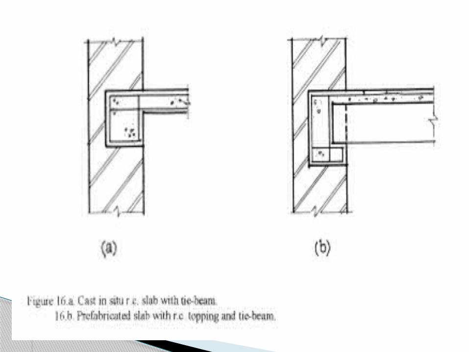
Floors and Roofs During earthquakes, floors and roofs should act as rigid horizontal diaphragms, which distribute the seismic forces among structural walls in proportion to their stiffness. One of the main reasons for the poor behaviour of existing masonry buildings is a lack of proper horizontal diaphragm action of floor and roof structures and or lack of proper connections between them and the structural walls which carry them. Use of timber floors and roofs in high-risk seismic zones is only recommended where the requisite carpentry skills exist and if specially designed details to ensure the integrity of these elements and their anchorage to the supporting walls.

Jack arches in lime mortar spanning between steel joists are adequate, provided the spans do not exceed 900 mm and steel cross bracing welded to corners of the outer joists above on the upper surface of the floor or roof is provided. Use of deformed bars for this is not allowed because they produce brittle welded joints. In the case of reinforced concrete floors and roofs, two-way slabs are to be used in preference to one-way slabs. Connections to walls are to follow the details illustrated in Figure

Tie Beams The function of tie beams is to transfer horizontal shear induced by the earthquakes from the floor and roof to the structural walls. They connect the structural walls with each other and improve the rigidity of the horizontal diaphragms. Tie beams should not be smaller in section than 150 x 150 mm. The reinforcement should not be less than 4 no. 12mm ø with stirrups 6 mm ø at 200 mm centres. Reinforcement should be spliced and anchored at cornets and wall intersections. Bars should overlap by a minimum distance of 60 times the diameters of the bars. Parapets should be reinforced vertically and horizontally. The reinforcement should be tied in with the reinforcement in the tie beam.

Cantilever Slabs and overhangsThese elements can cause harmful vertical vibration during heavy earthquakes. To reduce this, spans should not exceed those shown on Figure

THANKYOU