as318984 from coding to visualization, the integration of
TRANSCRIPT

AS318984
From coding to visualization, the integration of IES light automated framework
Imad Hanna American University in Dubai Mustafa Salaheldin Ali SNC-Lavalin Atkins Description Engineers, Architects and Designers are persistently constrained to provide a greater performance and better solutions when it comes to applying light effectively. Our process will enhance the BIM collaboration level and address how Generative Design can help manufacturers to produce more with less resources, energy and time to support sustainability. This class will go beyond the fundamentals of interior design lighting and dive into settings to promptly prototyped an automated system that can understand the requirements for the photometric light, select proper schemes, and calculate the level of lighting. We will learn how to link the IES files to any light rendering software then by altering the code preferences we can achieve accurate visuals that can be adjusted and updated at real time. The chosen design will be automatically translated into BIM data that will generate electrical plans and instantly calculate the intensity and quantity of light required for a particular space. In this class, you will discover how to create native Revit content as well as how to do project setup directly from a web portal. In this class, we will demonstrate how we used the Design Automation for Revit API to implement:
1. Identify the automated system that can understand the requirements of IES light to simulate design criteria real time
2. Calculate the quantity of light needed for a particular space where certain activities are performed.
3. Explain the link between design and application in order to generate electrical design sheets and QTO schedules using BIM
4. Learn how to classify and objectify fundamental abilities of Generative Design to customize a sustainability framework.

Speaker(s) Imad Hanna
Imad is an assistant professor at the American University in Dubai, a confident and competent Interior Architect with extensive experience in working on a different range of projects ranging from design to execution. He graduated from the University of Holy Spirit USEK (Kaslik- Lebanon) as an Interior Designer and accomplished his Master in Interior Architecture in 2008-2009. His interest in mixing architectural concepts with the latest technologies made him an expert in the Digital Design Fabrication field. Imad is a 3d studio Max (Autodesk certified professional) and (Adobe Certified Expert).
He focused on researching new and innovative platforms, applications and theories in Interior Design and architecture. Imad worked on developing and implementing educational technology curriculum for delivery of classroom using a combination of Autodesk Software.
He Received a certificate from Harvard “Teaching and learning strategies for higher education “
Along with several certificates of appreciation for being an active member in the NASAD accreditation so as for his contribution to the success of the CIDA – Council Of Interior Design Accreditation at the American University in Dubai. Imad is Member of the research committee at the American University in Dubai, an Associate member of the American Institute of Architects (AIA), the Association of Professional Interior Designers (APID) and the Interior Design Education Council (IDEC)
Mustafa Salaheldin A multi-disciplinary subject-matter expert and one of the few professionals in the Digital Transformation field who has a strong technical experience of BIM and is mastering the full-stack application development at the same time. Mustafa joined Atkins Middle East and Africa, part of the SNC-Lavalin Group in Canada, as the Data Science Manager. In the middle of the pace of technology there was a necessity for him to start looking at applying new techniques like Machine Learning (ML) and Artificial Intelligence (AI) to make use of the capacity of the machines to help in solving design issues and provide optimum designs. Previously working for Engineering Consultants Group (ECG) in Egypt as the head of BIM R&D, he started up the BIM implementation and automation. Besides he has a Bc.S. in Computer and systems engineering, he is a LEED GA certified, Autodesk Expert Elite, Microsoft certified applications developer and Autodesk Authorized Developer.

Introduction
Why Lighting Design? Architects, designers and engineers are constantly working on developing the best approach to light implementation using a variety of lighting types and distribution methods. Using light in an effective way to create different moods and atmospheres that can reflect the conceptual aspect and to serve the sustainability objective. It is extremely important to understand the perception of the space and the role of lighting and it is impact on the overall design. Therefore, we need to master the technical part along with the ascetic approach in order to achieve a great result. One of the most complicated tasks is to genuinely choose and calculate the suitable type and the required number of luminaires needed for a given space where certain activities are to take place.
Luminaires: choose luminaires that maximize the operating function that is unique to each lamp. Place them properly to provide effective lighting for specific tasks. Controls and maintenance: people are happier with a more flexible control system. Factors to consider: -space planning, schedules, activities, characteristics of the users, daylight and the interior environment.

Lighting Design and sustainability Sustainable design is an integrated, collaborative process that is changing the traditional roles and relationships of the architect, lighting designer, electrical engineer, and manufacturer. By including lighting design issues from the beginning of a project, green design goals can be best addressed. During each phase of the design process, lighting concerns can help guide overall building performance considerations.
Analyzing the space openings and Calculation of day light: According to the Whole Building Design Guide, daylighting is defined as “the controlled admission of natural into a building to reduce electric lighting and saving energy. Daylighting helps create a visually stimulating and productive environment for building occupants, while reducing as much as one-third of total building energy costs.”
Key factors where lighting design can have an impact:
1. Maximizing daylight, it is an important element of sustainable design. The incorporation of daylight in the design of a building is justified for a number of reasons: a. Aesthetics b. Color quality c. Energy savings d. Health benefit to occupants
2. Consider your ‘daylight delivery systems’
a. Skylights/roof lights b. Windows c. Light shelves
3. Minimize air, water and soil pollution (lamp selection) 4. Protect natural habitats (light pollution) 5. Eliminate toxic substances (lamp selection) 6. Recycle lamps (building operations) 7. Reduce light pollution and light trespass (lamp selection and lighting design)
When daylight is integrated with the electric lighting control system within a building, the electric lighting system may be either dimmed or switched off entirely to provide substantial savings in the amount of electric lighting energy required.
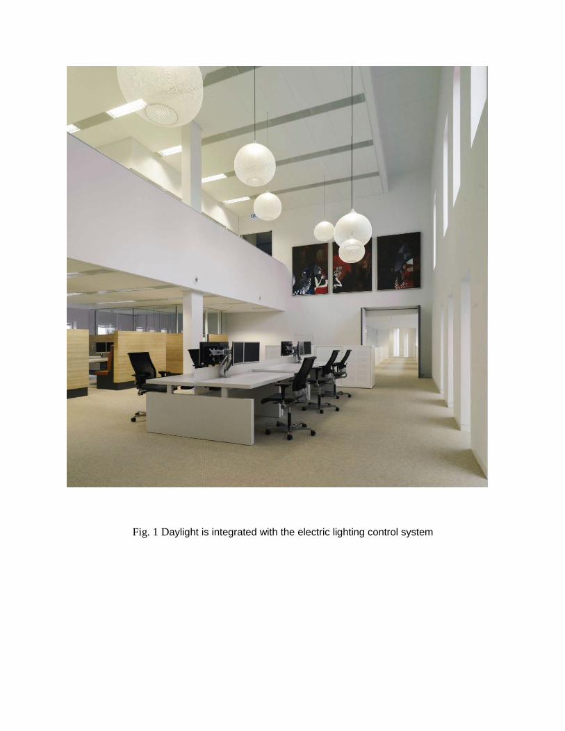
Fig. 1 Daylight is integrated with the electric lighting control system

How modern technology can help in enhancing sustainable lighting design?
The implementation of the automated design framework and the generative design in the same platform offers the users an opportunity to work on a different range of projects that can alter between lighting design, electrical engineering and design manufacturing or even all at once.
Our aim is that novice and expert practitioners can generate valid results and work on supporting the role of sustainability knowing that Design automation and Generative design abilities can help generating sustainable products by offering innovative design solutions that use less material, consolidate parts, and increase performance.
The automated solutions and the additive, subtractive and formative manufacturing technologies simplifies fabrication processes and ultimately decreases the impact your product has on the environment.
For more details on how Autodesk Revit – insight can offer the flexibility to create an accurate analytical lighting design solutions that can improve sustainability, kindly refer to appendix I
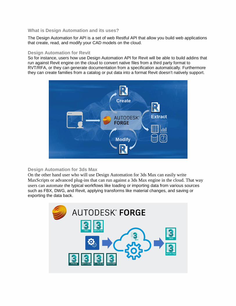
What is Design Automation and its uses? The Design Automation for API is a set of web Restful API that allow you build web applications that create, read, and modify your CAD models on the cloud. Design Automation for Revit So for instance, users how use Design Automation API for Revit will be able to build addins that run against Revit engine on the cloud to convert native files from a third party format to RVT/RFA, or they can generate documentation from a specification automatically. Furthermore they can create families from a catalog or put data into a format Revit doesn’t natively support.
Design Automation for 3ds Max On the other hand user who will use Design Automation for 3ds Max can easily write MaxScripts or advanced plug-ins that can run against a 3ds Max engine in the cloud. That way users can automate the typical workflows like loading or importing data from various sources such as FBX, DWG, and Revit, applying transforms like material changes, and saving or exporting the data back.

Terminology: There is some important terminology, which we should be aware of, in order to be able to develop the application.
Fig.2 Automation Design API Components
In the following list you can find the main definitions and terms used:
• Activity: The specification of an action that can be executed using a specified engine. • WorkItem: A job that executes a specified Activity, using specified input files and generating
appropriate output files. • : A module referenced by an Activity in order to perform specific functions. Typically, this is a
DLL or some other form of custom code. • Engine: The actual processing engine that runs the WorkItem job and processes the
Activity. • NickName: A nickname is a way to map a Forge App ClientId to a customized string. A
nickname lets you create a friendly, easy-to-read string that can be used in place of the long Forge App ClientId.
• Alias: An alias is a label to a specific version of app or activity. Aliasing gives you more control over how you update appbundles and activities.
Design Automation, Design Automation for Revit, DA, DA4R and Revit.io will be used interchangeably to refer to the same thing. Why Forge Design Automation? There is no difference between writing a code using the DA API and writing the code for a regular CAD add-in, they are almost equivalent except that in DA you don’t have access to the UI components to the CAD application interface and you only limited to address the db. Because Design Automation API is a Forge service, you can take advantage of other Forge services to easily connect your applications together.

On top of that, you can make extend the DA API abilities by giving it unlimited access to all cloud service from other vendors. You can use advanced features like Amazon Lambda functions or plug your add-in to the ML and AI provided from Microsoft or Google for example.
Fig.3 Revit.io integration with cloud-platforms

What is generative design? Generative design mimics nature’s evolutionary approach to design, leverages artificial intelligence and cloud computing by allowing users to simultaneously generate and explore multiple CAD-ready solutions based on real-world manufacturing constraints and product performance requirements. Designers, Architects and engineers input design objectives into generative design software, along with parameters such as loads, materials, and manufacturing methods and cost constraints. The software explores all the possible variations of a solution, rapidly generating design alternatives. It tests and learns from each recapitulation what works and what doesn’t.
Algorithmic or Generative design is not simply the use of computer to design architecture and objects. Algorithms allow designers to overcome the limitations of traditional CAD software and

3D modelers, reaching a level of complexity and control which is beyond the human manual ability. Algorithms-Aided Design presents design methods developed in software like Fusion 360*. A visual algorithm editor allowing users to explore accurate freeform shapes that uses computational techniques to develop and control complex geometries, covering parametric modeling, digital fabrication techniques, form-finding strategies, environmental analysis and structural optimization. With generative design, there is no single solution; instead, there are potentially thousands of great solutions. You choose the design that best fits your needs.
* For more details about Generative design using Fusion 360 kindly refer to appendix

Why Generative Design? Product design breaks down into four categories and they are Function of the part, Materials used, Manufacturing Process, and how it needs to perform. Here we want to explore how these four categories differ between the products. Traditional Optimization To enable Traditional Optimization users can start with a basic concept or design and allow the software to analyze and refine the proposal. Function of the Part The function of the part is a mix of Loads and forces that are applied to the part and known physical constraints that restrict the space and mounting points. In traditional design methods you take the information toy know and mix that with traditional shapes to develop a couple of concepts then you run an analysis on each to look for the best performance. With generative design you build bodies that represent preserved areas, obstacles, and starting shapes. You will apply loads and constraints to these bodies to help define the function of the part. Materials of the Part The material that is used for the part design can very and has a direct effect on the strength of the part. With traditional design the material is not always known till the part is created so you start with a single material that adjust based on the outcome of the analysis.
With generative design you assign multiple materials so that you can optimize your design process
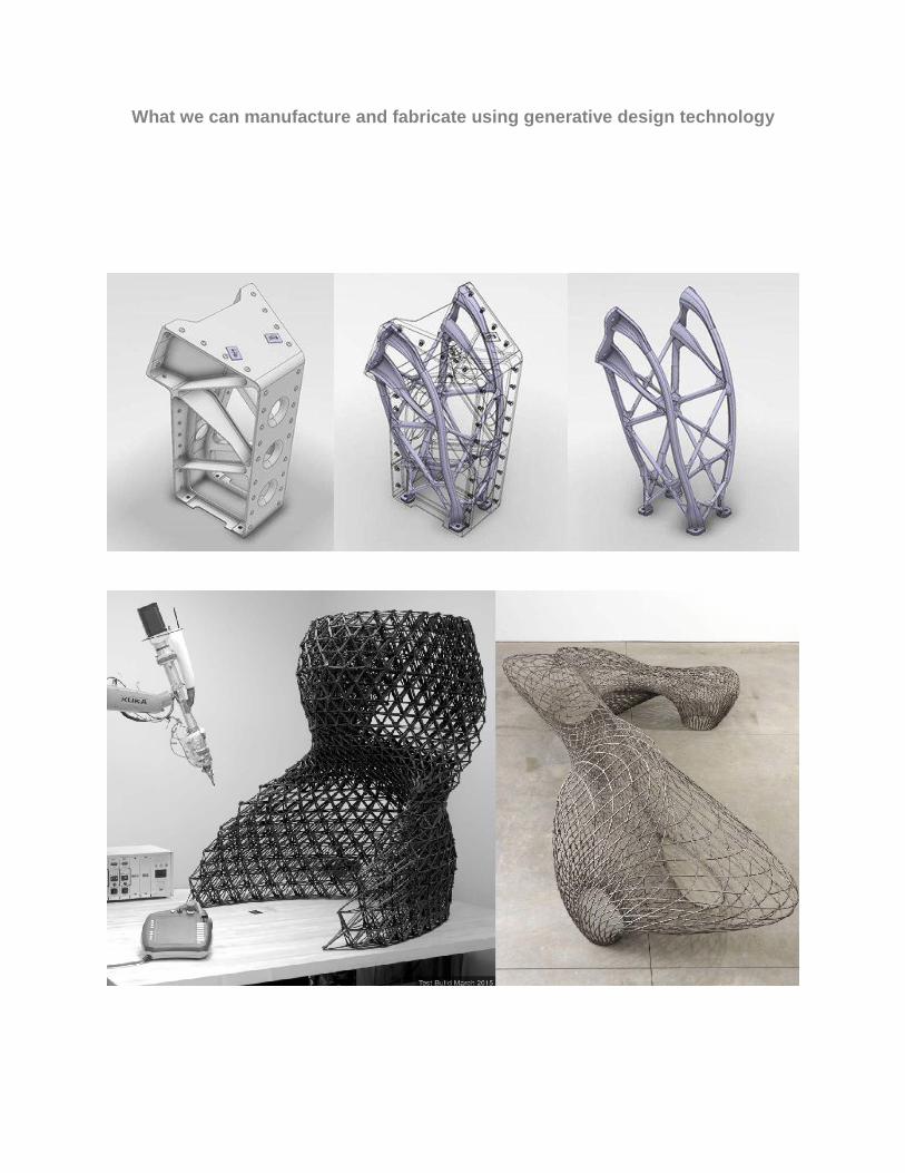
What we can manufacture and fabricate using generative design technology


* For more details about how Fusion 360 can facilitate the process of design manufacturing using Slice for Fusion 360 kindly refer to appendix I

Concept Idea behind our platform Our purpose is to provide a user friendly tool, with a simple user interface that can automates most of the processes of preparing a lighting project, starting by simulating your own visual lighting design, generating RCP and BOQ ending with a product ready for manufacturing.
Fig. 2 Different modules of our platform (Visualization, BIM, and Fabrication
We are focusing on the photometric IES light, but not like any other lighting generator the platform has the capability to translate your own parameters into IES simple basic codes
creating a layout and setting up views that can be updated automatically. Using forge API the platform will be connected to 3D Studio Max and will instantly crated visual renders for your
chosen IES light.

Once you are satisfied with the selection of your lighting design and IES file we move to the second section of our platform where you can upload your Revit file and the platform will work on dividing the space into rooms so you can manipulate each space independently. The automated system will be responsible for the light distribution of the selected space and will generate a Revit file with the RCP and the BOQ that you can download with a simple click.
The last step will be under Manufacturing a 3rd part of the platform where Generative design will take place. The user will be capable to upload the same IES file and specify the
descriptions: size, weight and desired material of the luminaire and with a simple click the platform will Generate a hundreds of options and designs for the product.
To insure that the platform is valuable for collaboration between professional architects, designers, expert consultants and engineers, we will provide a deeper explanation of the
conceptual automated methods, and will access to the layers of information behind the main idea.
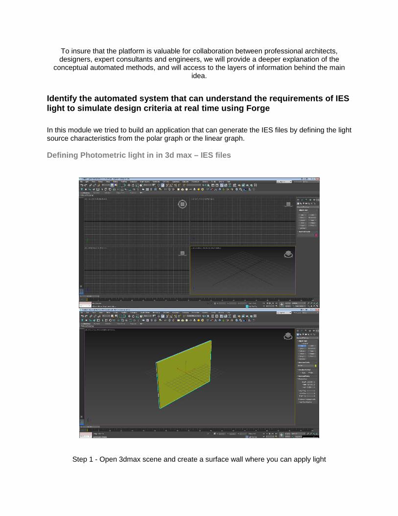
Identify the automated system that can understand the requirements of IES light to simulate design criteria at real time using Forge In this module we tried to build an application that can generate the IES files by defining the light source characteristics from the polar graph or the linear graph. Defining Photometric light in in 3d max – IES files
Step 1 - Open 3dmax scene and create a surface wall where you can apply light

Step 2 – select light and choose Photometric Light Step 3 – specify the light type / Target Light

Step 4 – Assign light to the scene

Step 5 – under Light distribution select the Photometric Web Step 6 – under distribution Photometric select choose photometric file

Step 7 – specify the IES File

Step 8 –the Photometric Web will be uploaded and the IES will be assigned to the scene
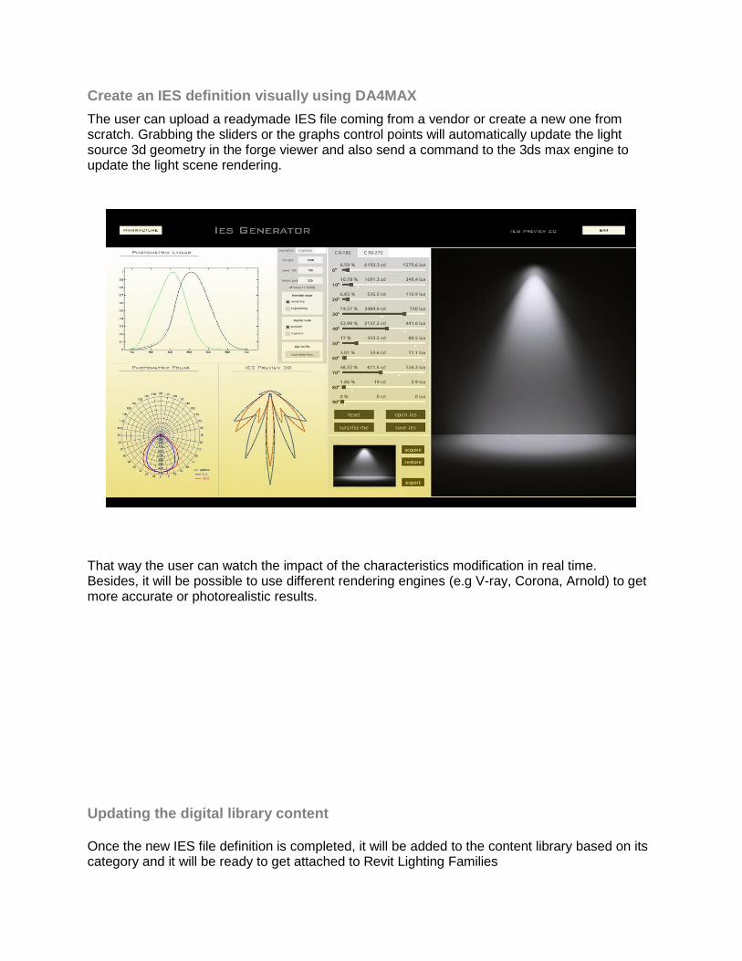
Create an IES definition visually using DA4MAX The user can upload a readymade IES file coming from a vendor or create a new one from scratch. Grabbing the sliders or the graphs control points will automatically update the light source 3d geometry in the forge viewer and also send a command to the 3ds max engine to update the light scene rendering.
That way the user can watch the impact of the characteristics modification in real time. Besides, it will be possible to use different rendering engines (e.g V-ray, Corona, Arnold) to get more accurate or photorealistic results. Updating the digital library content Once the new IES file definition is completed, it will be added to the content library based on its category and it will be ready to get attached to Revit Lighting Families

Calculate the amount of light needed for a particular space where certain activities are performed It is very important to decide the amount of light needed for any building based on different factors like the location, daylight and the type of activities taking place in the facility. Our system can calculate such factors and evaluates the amount of light and the type of luminaires needed for each room/space, hence update the Revit model using the Forge Design Automation for Revit API with the proper type of lighting fixtures.
Fig.5 Updating the Revit model with Revit.io


Explain the link between design and application in order to generate electrical design sheets and QTO schedules using BIM Once the user is satisfied with the final lighting distribution and lighting fixtures types, we can send another command to Revit.io to automatically generate the ceiling/floor plans sheets and moreover generates the BoQ needed for each plan or building. The generated BoQ can be exported as an Excel sheet and can be linked to any database source or cloud services like Google Sheets, that way the changes and updates could be bi-directional, meaning if you update the Excel sheet it will update the lighting model elements and vice versa.


Learn how to classify and objectify fundamental abilities of Generative Design to customize a sustainability framework The most critical point for both designers and manufacturers is how to make the optimum choice for their products from a set of several options, here comes the role of generative design. In our system we used the generative design to generate different design options for lighting fixtures to help the designers make better choices based on the visual results.

For the manufacturers, it is very easy now to select the shape of the laminar, the reflector material, and number of light sources per luminaire that can achieve certain illumination level.
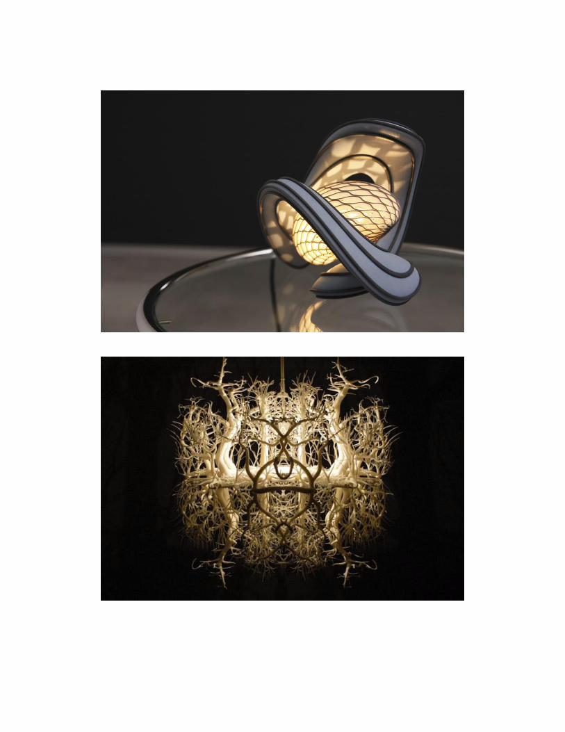
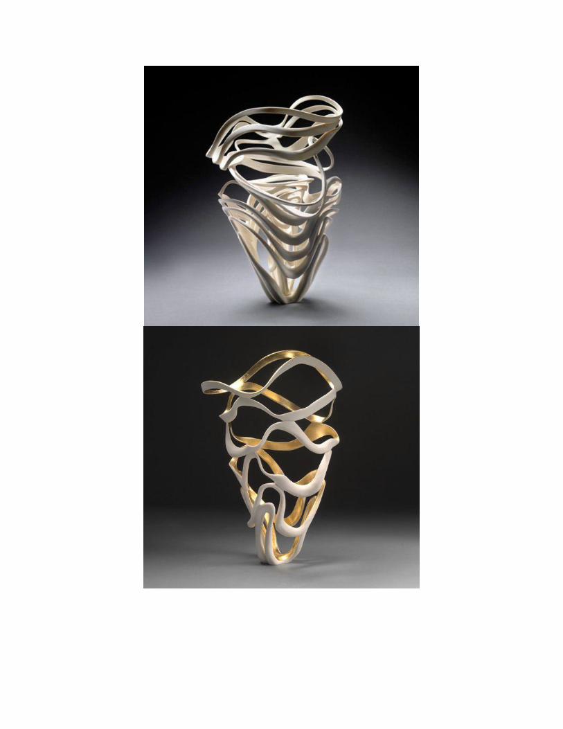
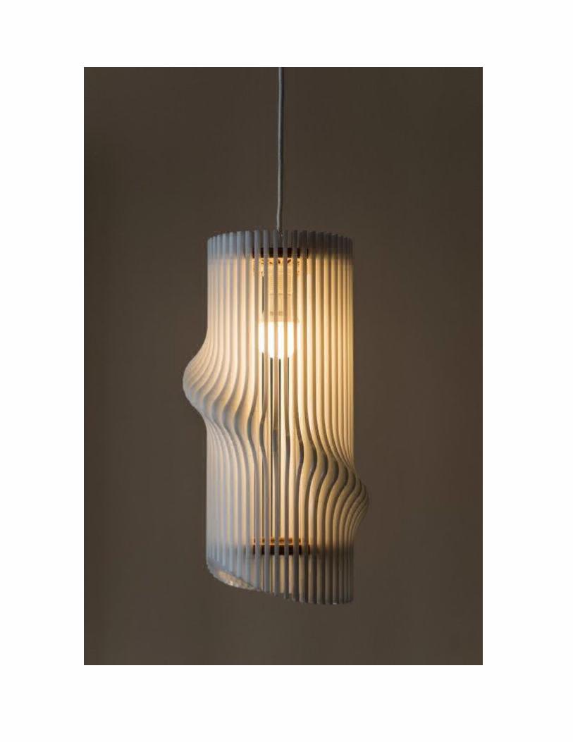
Samples of GD for lighting Here we are listing a variety of generated design Luminaires from different manufacturers and designer that could be found on the internet:


Conclusion With new technologies constantly emerging, companies need to be at the forefront in order to continue providing competitive and relevant offerings to their clients. The evolution of the lighting design industry dictates a shift in which companies need to adapt to the new challenges and changes.
As we have demonstrated in our class, Autodesk technologies are offering the best solutions to facilitate the lighting design and manufacturing process by providing a variety of API for design automation.
Autodesk Technologies gave us the ability to benefit from the power of Generative Design where users are free to select from a CAD generated variety of design options and create many solutions simultaneously. Generative design is a definitive shift in how to conceptualize, design, and build. This strategy will augments human capabilities by using algorithms to automate your design logic.
Now we do have a clear idea on how to glue the new technologies with the BIM standards in order to achieve a collaborative design process between different disciplines of different phases. Architects, engineers and designers are capable to analyze the space requirements and calculate its suitable amount of light by respecting and supporting the role of sustainability in the advancement of green and smart buildings.

Appendix I
Insight-Revit (Daylighting Analysis)
Insight is a plugin used for environmental analysis for Autodesk Revit one of the many beneficial features for it is the daylighting efficiency analysis to help optimize the use of artificial light in the space.

Steps
1. From the analyze toolbar select the location of the project from energy optimization section
2. Select lighting from insight section also under analyze toolbar
3. Choose Run new analysis
4. Press on GO button
• Choose the type of analysis
• Select the level desired for diagram
• Select desired resolution
• Start analysis
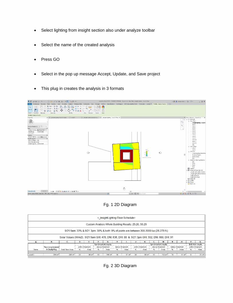
• Select lighting from insight section also under analyze toolbar
• Select the name of the created analysis
• Press GO
• Select in the pop up message Accept, Update, and Save project
• This plug in creates the analysis in 3 formats
Fg. 1 2D Diagram
Fg. 2 3D Diagram

Fg. 3 Schedules

Appendix II How do you get access to Generative Design? Generative design is available to Fusion 360 commercial subscribers, and Product Design and Manufacturing Collection subscribers.
What are the basic steps in setting up a Generative Design?
1. Open or create the model in Fusion 360. 2. Enter the ‘Generative Design’ workspace. 3. If needed, modify the geometry in the ‘Edit Model’ workspace to prepare the
preserve, obstacle, and starting shape geometries to be defined in the next step. 4. Define design space, including Preserves, Obstacles, and/or Starting Shapes. 5. Define loading conditions and constraints. 6. Define objectives. 7. Define manufacturing method, including unrestricted, additive, or 3/5-axis milling. 8. Define material options (up to 10). 9. Generate outcomes – if converged, the outcome satisfies all design requirements
specified. 10. Explore outcomes & export the optimal solution.


Appendix III
3D Printing Materials and Finishes Some of the most common and reliable metals for 3D printing include stainless steel, aluminum, titanium, cobalt chrome and Inconel alloy. Choosing the best material is vital for ensuring parts will perform as needed. Another design aspect to consider before going with choosing 3D metal printing is the desired surface finish. The surface finish of 3D printed part is poor due to it being built layer by layer. It takes post-machining on printed parts to get aesthetically pleasing surface finishes. This can be done using CNC machining or manual surface grinding, sanding, or polishing. It may seem obvious, but size is another limed parameter. Parts cannot be larger than the machine’s build platform, which varies from printer to printer. Although there is no standard Build-platform size, the most common dimensions are around 250 × 250 × 300 mm, or smaller.
Heat sinks for LED light sources:
a) Industrial design solutions; b) Topology-optimized LED heat sinks for vertical, and horizontal orientations with 1/2 and 1/8 symmetries; c) 3D printed topology-optimized design with additional
support; post-processed design with removed support; and simplified interpretation manufactured by traditional techniques.
Source : https://www.3dprinting.lighting/

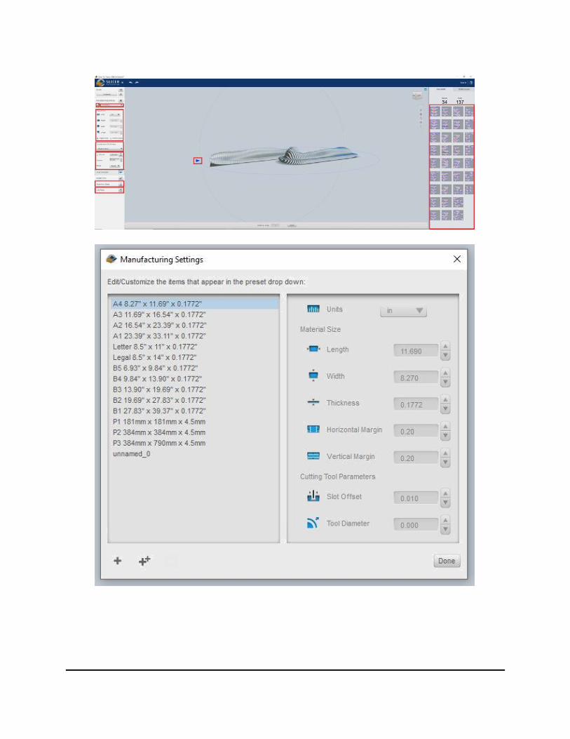
Slicer for Fusion 360 (Fabrication)
Slicer for fusion is an Autodesk developed plug in/ independent software that is used to convert in a 3d model into a manufactural product with pieces for laser cutting numbered with an assembly guide for it.


Steps
1. Open the desired fusion model 2. Open Tools Toolbar 3. Select the drop down menu from Make Icon 4. Choose from it Slicer for Fusion 360 5. Select the desired body to manufacture 6. Change the quality to hi
P.S. If the user is using any other software the Slicer reads Obj and STL file
7. When the Slicer Opens Choose from the Variety of materials available with sizes and thicknesses • If not found the desired one you can edit and add your own new material
8. Adjust the options of the construction techniques 9. Change slicing Direction by Selecting the circle the dragging the blue arrow 10. Press on Get Plans 11. Download DXF Files 12. Press on assembly steps to preview the method of assembling the Model

• https://www.google.com/search?q=generative+design+lighting+fixtures&safe=active&source=lnms&tbm=isch&sa=X&ved=0ahUKEwjxurfKqpbkAhUURhUIHYIXBJQQ_AUIESgB&biw=1892&bih=936
• HTTPS://WWW.MICROSOFT.COM/EN-
US/HOLOLENSHTTPS://WWW.AUTODESK.COM/PRODUCTS/FUSION-360/OVERVIEWHTTPS://WWW.WIRED.COM/2017/05/THE-SHATTERING-TRUTH-OF-3D-PRINTED-
• CLOTHING/HTTPS://WWW.GOOGLE.AE/SEARCH?Q=DIGITAL+DESIGN+FABRICAT
ION+AND+TECHNOLOGY&DCR=0&SOURCE=LNMS&TBM=ISCH&SA=X&VED=0AHUKEWIWKCFZS4HYAHWC_KQKHZDCBWYQ_AUIDCGD&BIW=1920&BIH=974
• https://www.pinterest.com/pin/332984966168316774/
• https://www.google.com/search?q=generative+design+lighting+fixtures&safe=acti
ve&source=lnms&tbm=isch&sa=X&ved=0ahUKEwjxurfKqpbkAhUURhUIHYIXBJQQ_AUIESgB&biw=1892&bih=936#imgrc=kT9Fic9Xep5gfM:
• https://www.3dprinting.lighting/
• https://www.pinterest.com
Graphical material in this presentation are used for non –profit seminar within educational context.