assembly diagram and assembly reference ultima old school 2
TRANSCRIPT

ASSEMBLY DIAGRAM AND ASSEMBLY REFERENCE ULTIMA OLD SCHOOL 2” EVO & TC BELT DRIVE UNITS
BELT DRIVE ASSEMBLIES
Part# 58-850 2” Old School Belt Drive Assembly - PolishedPart# 58-851 2” Old School Belt Drive Assembly - Machine finish
REV 9-08-14

ASSEMBLY DIAGRAM AND ASSEMBLY REFERENCE ULTIMA OLD SCHOOL 2” BELT DRIVE UNITS
BELT DRIVE PRODUCTS
WARRANTY PROVISIONSUltima’s component parts used in our Belt Drives are guaranteed to the original purchaser to be free of manufacturingdefects in materials and workmanship for a period of Twelve (12) months from the date of purchase through MidwestMotorcycle Supply.Merchandise that fails to conform to these conditions will be repaired by Ultima if the parts are returned to MidwestMotorcycle Supply by the purchaser within the 12-month warranty period or within 10 days thereafter.Some problems can be rectified by a telephone call and need no further course of action. A part that is suspected of beingdefective must not be replaced by a Dealer without prior authorization from Midwest Motorcycle Supply. If it is deemednecessary for Ultima to make an evaluation to determine whether the part was defective, it must be packaged properly toprevent further damage and be returned prepaid to Midwest Motorcycle Supply with a copy of the original invoice ofpurchase and detailed letter outlining the nature of the problem, how the part was used and the circumstances at the timeof failure. If, after an evaluation has been made by Ultima and the part was found to be defective, repair or replacementwill be granted at Ultima’s discretion.
ADDITIONAL WARRANTY PROVISIONS:1. Ultima shall have no obligation in the event an Ultima part is modified by any other person or organization.2. Ultima shall have no obligation in the event an Ultima part becomes defective in whole or in part as a result of improperinstallation, improper maintenance, improper use, abnormal operation, or any other misuse or mistreatment of the Ultimapart.3. Ultima shall not be liable for any consequential or incidental damage resulting from the failure of an Ultima part, thebreach of any warranties, the failure to deliver, delay in delivery, delivery in non-conforming condition, or for any otherbreach of contract or duty between Ultima and a customer.4. These Diagrams are provided for a reference only and in no way imply that this part is suitable for the applications it isbeing installed to. The Part #’s these Diagram reference were designed to fit OEM Softail® Style Motorcycles made from1990-1999 with exception to the starter drive assembly which uses the 1989-1993 diameter jackshaft bolt (1/4-20). TheseDrives will also fit most aftermarket Softail and Rigid Frames designed to use Softail style components made within theseyears.
PROFESSIONAL INSTALLATION REQUIREMENTS:Ultima Belt Drives should be installed by trained professional mechanics into motorcycle in which they were intended foruse. Failure to do so may result in injury and even death. It is the customer’s responsibility to insure their mechanic hasproper training.
PREPARATION FOR ASSEMBLYBefore installing the Ultima Belt Drive System you must remove your entire existing primary drive. This also includes thepressed on transmission mainshaft race used with chain drive inner primary bearings.As stated earlier the Ultima Belt Drive System requires the use of a 1989-1993 type starter drive shaft which utilizes thelarger 1/4-20 fastener. We also suggest using any of our heavy duty Ultima Thunder Fire Starters part # 70-220 thru 70-229 which incorporate both 89/93 and 94/Later style drive shaft bolt arrangements. These starters are available in 1.4,1.75, 2.0 and 2.4 Kw configurations.Ultima Belt Drives utilize a slightly longer center distance between the pulley’s and will require that you loosen thetransmission mounting bolts to allow the transmission move back approx .040”. At this time we suggest inspection of your Charging System. Ultima Belt Drives are designed to work with most 32 ampCharging System on the market today. Later model 38, 40 and 44 amp systems may interfere with the Motor Plate. While you are inspecting the alternator we highly recommend that you install a new Crankshaft Seal on the enginereplacing the existing seal with a High Quality double lip seal and installing the seal with the steel face out. Belt DriveUnits require a dry environment free from Oil and by flipping the oil seal you ensure any crankcase pressure and oil willstay in your engine. This is also a great time to inspect the transmission sprocket and seal for wear and to ensure thesprocket is tight.
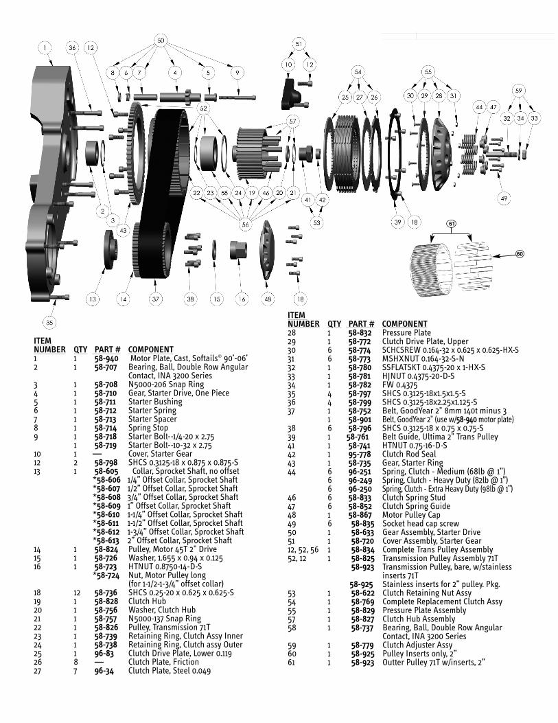
ITEM NUMBER QTY PART # COMPONENT1 1 58-940 Motor Plate, Cast, Softails® 90’-06’2 1 58-707 Bearing, Ball, Double Row Angular
Contact, INA 3200 Series3 1 58-708 N5000-206 Snap Ring 4 1 58-710 Gear, Starter Drive, One Piece5 1 58-711 Starter Bushing6 1 58-712 Starter Spring7 1 58-713 Starter Spacer8 1 58-714 Spring Stop9 1 58-718 Starter Bolt--1/4-20 x 2.75
1 58-719 Starter Bolt--10-32 x 2.7510 1 — Cover, Starter Gear12 2 58-798 SHCS 0.3125-18 x 0.875 x 0.875-S13 1 58-605 Collar, Sprocket Shaft, no offset
*58-606 1/4” Offset Collar, Sprocket Shaft*58-607 1/2” Offset Collar, Sprocket Shaft*58-608 3/4” Offset Collar, Sprocket Shaft*58-609 1” Offset Collar, Sprocket Shaft*58-610 1-1/4” Offset Collar, Sprocket Shaft*58-611 1-1/2” Offset Collar, Sprocket Shaft*58-612 1-3/4” Offset Collar, Sprocket Shaft*58-613 2” Offset Collar, Sprocket Shaft
14 1 58-824 Pulley, Motor 45T 2" Drive15 1 58-726 Washer, 1.655 x 0.94 x 0.12516 1 58-723 HTNUT 0.8750-14-D-S
*58-724 Nut, Motor Pulley long (for 1-1/2-1-3/4” offset collar)
18 12 58-736 SHCS 0.25-20 x 0.625 x 0.625-S19 1 58-828 Clutch Hub20 1 58-756 Washer, Clutch Hub21 1 58-757 N5000-137 Snap Ring22 1 58-826 Pulley, Transmission 71T23 1 58-739 Retaining Ring, Clutch Assy Inner24 1 58-738 Retaining Ring, Clutch assy Outer25 1 96-83 Clutch Drive Plate, Lower 0.11926 8 — Clutch Plate, Friction27 7 96-34 Clutch Plate, Steel 0.049
ITEM NUMBER QTY PART # COMPONENT28 1 58-832 Pressure Plate29 1 58-772 Clutch Drive Plate, Upper30 6 58-774 SCHCSREW 0.164-32 x 0.625 x 0.625-HX-S31 6 58-773 MSHXNUT 0.164-32-S-N32 1 58-780 SSFLATSKT 0.4375-20 x 1-HX-S33 1 58-781 HJNUT 0.4375-20-D-S34 1 58-782 FW 0.437535 4 58-797 SHCS 0.3125-18x1.5x1.5-S36 4 58-799 SHCS 0.3125-18x2.25x1.125-S37 1 58-752 Belt, GoodYear 2" 8mm 140t minus 3
1 58-901 Belt, GoodYear 2" (use w/58-940motor plate)38 6 58-796 SHCS 0.3125-18 x 0.75 x 0.75-S39 1 58-761 Belt Guide, Ultima 2" Trans Pulley41 1 58-741 HTNUT 0.75-16-D-S42 1 95-778 Clutch Rod Seal43 1 58-735 Gear, Starter Ring44 6 96-251 Spring, Clutch - Medium (68lb @ 1”)
6 96-249 Spring, Clutch - Heavy Duty (82lb @ 1”)6 96-250 Spring, Clutch - Extra Heavy Duty (98lb @ 1”)
46 6 58-833 Clutch Spring Stud47 6 58-852 Clutch Spring Guide48 1 58-867 Motor Pulley Cap49 6 58-835 Socket head cap screw50 1 58-633 Gear Assembly, Starter Drive51 1 58-720 Cover Assembly, Starter Gear12, 52, 56 1 58-834 Complete Trans Pulley Assembly52, 12 1 58-825 Transmission Pulley Assembly 71T
58-923 Transmission Pulley, bare, w/stainless inserts 71T
58-925 Stainless inserts for 2” pulley. Pkg.53 1 58-622 Clutch Retaining Nut Assy54 1 58-769 Complete Replacement Clutch Assy55 1 58-829 Pressure Plate Assembly57 1 58-827 Clutch Hub Assembly58 1 58-737 Bearing, Ball, Double Row Angular
Contact, INA 3200 Series59 1 58-779 Clutch Adjuster Assy60 1 58-925 Pulley Inserts only, 2”61 1 58-923 Outter Pulley 71T w/inserts, 2”
60
61

I. SELECTING THE PROPER OFFSET PULLEY INSERT
Ultima Drives use 6 bolts to fasten the Motor Pulley to the Pulley Insert. Install these bolts using Red Loctite and Tighten to 18-22 ft lbtorque. All Ultima Drives include the Stock offset Spacer. The Following Spacers are available separately for Wide Tire Applications.MWM # 58-606 .250” Offset MWM # 58-608 .750” Offset MWM # 58-611 1.5” OffsetMWM # 58-607 .500” Offset MWM # 58-609 1.00” Offset MWM # 58-612 1.75” Offset
MWM # 58-610 1.25” Offset MWM # 58-613 2.00” Offset
When use of a 1-1/2” to 2” offset is needed, you must purchase Midwest Part#58-724 motor pulley nut.
II. INSTALLING THE MOTOR PLATE
Install the Motor Plate without the rubber o-ring for the inner primary to engine. Remember the center distance will be different with the UltimaBelt Drive so it will require you to move the transmission. Align the motor plate to the engine and transmission then install the mounting boltsfor the engine and trans snug only. You might need a dead blow or plastic hammer to seat the motor plate over the transmissions dowel pin.With the motor plate mounting bolts lightly snug to the engine and tightened to the transmission look to see that the trans is sitting square onthe frame. Shimming is generally not required but needs to be inspected for spaces no larger than .030”. If all looks good begin by pulling thetransmission mounting nuts tight. Next run the Motor Plate to the engine bolts tight. Next check the motor plate to trans mounting bolts fortight. If all aligns well your ready to Start removing the Motor Plate to engine and trans bolts to apply RED Loctite one at a time. Torque all to18-22ft lb.

III. INSTALLING PULLEYS AND BELT
Install the clutch Basket Assembly onto the transmission mainshaft. ApplyRED Loctite to the mainshaft nut and torque to 55-65 ft lb.
1.
Install the Stator Rotor Washer and any Shims that were present. Ultima Belt Drives are not as sensitive as chain drives to pulleyalignment as the clutch basket acts as a guide but proper alignment should be checked. To insure a completely dry runningprimary many people use a bead of clear RTV Silicone at each spline to insure no oil will travel between the shaft and spline.Install the belt and front pulley at the same time. It can be tricky to align the splines with some tension on the belt. Once you getthe spline started you can tap the pulley on lightly with a dead blow or plastic hammer.
2.
Install the motor pulley nut using RED Loctite and Torque to Mfgrecommended Specification.
3.

IV. INSTALLING THE CLUTCH COMPONENTS
Ultima Belt Drive utilize 8 of the old style 900cc sportster steel drive plates and 8 special size fiber platesdesigned to provide a very adjustable Clutch Package. When Installing the Clutch Pack Install the Thick .119”Steel Plate First then Alternate Fiber/Steel. The Last Plate you install should be Fiber.
1.
Check the pressure plate screws to ensure they are all tight and the heads of the bolts are sitting belowthe plate surface.
2.
Install the clutch adjusting screw using a small amount of high temp grease or anti-sieze on the threadand especially on the Clutch Pushrod end. Don’t get too much grease out there –Remember this is a DRYclutch.
3.

Align the witness marks on the pressure plate and inner clutch hub as shown when installing pressure plate.This will ensure clutch hub studs will be centered in the appropriate pressure plate holes.
4.
witness marks
After installing pressure plate, install clutch springs w/supplied spring collars and narrow-headed 12-24 bolts. Installusing Blue Locktite. Spring collars should bottom on clutch hub studs. Torque to 90 in-lbs. In higher horsepower applications, heavier springs are available. Midwest Part#96-251 (68lbs @ 1”)Midwest Part#96-249 (82lbs @ 1”) Midwest Part#96-250 (98lbs @ 1”)
5.
NOTE: CENTER PUSHROD IS REQUIREDThe center clutch push rods (located in the transmission main shaft) mayneed to be changed depending on setup. Below is a list of availble sizes.
PART# LENGTH DESCRIPTION96-442 11.375” 1987-1989 5 speed96-538 10.8125” 1990+ 5 speed96-469 11.875” 1985+ 5 & 6 speed
At this time you will adjust your clutch. Thread in the adjuster until it makes contact w/the clutchpushrod. Once it is lightly seated, back adjuster off 1/4 turn. Using an 11/16” wrench, tighten theadjuster locknut. Clutch cable adjustment can now be done leaving some end play at the lever.
ADJUSTING THE CLUTCH

VI. INSTALLING PULLEY CAP AND CLUTCH TRIM RING
Install motor pulley cap and clutch basket trim ring at this time using the supplied 1/4-20bolts. Torque to 120-140 in-lbs w/Blue Loctite.
Check your kickstand clearance to the belt pushing down on the belt then adding at lease 1/2”.Use MWM # 5-190 Adjustable Kickstand Leg Stop if needed. This is an important safety check andshould be performed before initial startup.
VII. KICKSTAND CONSIDERATIONS
Install your starter motor to the Motor Plate then install the starter drive gear assembly in the order shown using Blue Loctite. TheStarter Drive Gear should be a Minimum of .150” from the clutch basket starter ring gear once installed. APPLY SOME HIGH TEMPGREASE OR ANTI-SIEZE TO THE STARTER END CAP BUSHING. Apply upward pressure to end cap when torquing to 18-22ftlbs, always use Blue Locktite on end cap bolts. Reapply grease to bushing every 6 months - DO NOT RUN DRY!
Starter Gear Assembly
V. INSTALLING THE STARTER GEAR