assembly instruction - solar-bazaar.com instruction deger ... the fact that the patent-protected...
TRANSCRIPT

Assembly Instruction
DEGER TOPtraker 40NT
Effective 2012-07-01

Assembly Instruction DEGER TOPtraker 40NT List of content
Assembly Instruction DEGER TOPtraker 40NT 2012-07-01
List of content
Part I Basics Introduction........................................................................................................................ Page I-1 General Instructions.......................................................................................................... Page I-2 Important safety instructions.............................................................................................. Page I-3 Warning notices……………………...............………………………………………………….. Page I-4 Short assembly instruction.…………………................………..……………………………... Page I-5 Scope of delivery............................................................................................................... Page I-6
Part II Foundation and mast Open area installation........................................................................................................ Page II-1 Open area installation....................................................................................................... Page II-2 Dimensions........................................................................................................................ Page II-3
Part III Structure Baseframe......................................................................................................................... Page III-1 Baseframe......................................................................................................................... Page III-2 Elevation motor (EMO)...................................................................................................... Page III-3 Elevation motor (EMO)...................................................................................................... Page III-4
Part IV Module carry system DEGER TOPtraker 40NT.................................................................................................. Page IV-1 Assembly aluminium profiles and modules....................................................................... Page IV-2 Assembly aluminium profiles and modules....................................................................... Page IV-3
Part V Control unit Assembly control unit......................................................................................................... Page V-1 Functional characteristics.................................................................................................. Page V-2 Datasheet energy converter II - TOPtraker....................................................................... Page V-3
Part VI Certificates Declaration of conformity................................................................................................... Page VI-1 TÜV-certificate................................................................................................................... Page VI-2 Declaration of commitment................................................................................................ Page VI-3
Part VII Troubleshooting / Maintenace Troubleshooting................................................................................................................ Page VII-1 Maintenance...................................................................................................................... Page VII-2 Maintenance...................................................................................................................... Page VII-3
Part VIII Protokols Report of implementing..................................................................................................... Page VIII-1 Fault report........................................................................................................................ Page VIII-2 List of tracking systems..................................................................................................... Page VIII-3 Company adress............................................................................................................... Page VIII-4
IMPORTANT INSTRUCTIONS!! Please pay attention to the instructions on Page I-1 and 2!

Assembly Instruction DEGER TOPtraker 40NT Part I - Basics
Introduction
Assembly Instruction DEGER TOPtraker 40NT 2012-07-01
Page I-1
Congratulation for aquiring a DEGER TOPtraker. You decided for a high quality single-axis solar tracking system which can be used for all current photovoltaic solar modules. Maximum solar yield... can be achieved with the DEGER TOPtraker tracking system. By using the DEGER TOPtraker tracking system, you are truly acknowledging the signs of our times: you are not only protecting our environment and nature but you are increasing your yield and thus achieving amortisation sooner. Maintenance-free. Long-lived. RecyclBasicsable. The systems designed to these exacting parameters are mass-produced in an ISO 9001-certified factory under environmentally sound conditions. DEGER TOPtraker systems are truly 99.9% recyclable. Compared with rigid systems, the amount of electronic scrap after useful life is 25% lower! Quick installation. Pre-assembled components and detailed instructions allow an installation within less than two hours (after the mast has been erected). A technology to rely on. The fact that the patent-protected control system were awarded the inventor’s prize of the federal state of Baden-Württemberg in South-Germany in 2000 shows that the DEGERtraker meets the demands of both experts and investors. Since this award the control unit and the mechanical system have been advanced continuously. Scope of delivery. Complete single-axis tracking system, mast, aluminium solar module carrier system to fit the respective module type, DEGERconecter control electronics with energy converter for extremely economical operation, foundation plan, construction plan. Environmental conditions The use of the DEGER TOPtrakers with Energiekonverter II – TOPTtraker is permissible for the following environmental conditions:
Site altitude above MSL (sea level): max. 2000m Permissible ambient temperature: -20°C to +55°C Sound level: Distance 10m: 40 dB(A)
Distance 20m: no difference to the sound level of the surrounding measurable
Reference value: 40 dB(A) corresponds to: - tweet of a bird
- usual background sound level in a house
IMPORTANT INSTRUCTIONS!! The start-up protocol should be filled out on initial operation and faxed to the company DEGERenergie within 4 weeks of start-up (at the latest 3 months after delivery). A fault report must be submitted in order to process complaints. Complaints cannot be
processed if fault reports have not been filled out correctly!!

Assembly Instruction DEGER TOPtraker 40NT Part I - Basics
General Instructions
Assembly Instruction DEGER TOPtraker 40NT 2012-07-01
Page I-2
DEGER TOPtrakers are essentially divided into 2 models: DEGER TOPtraker 40NT: maximum installable module area 40m²
Designed for wind speeds of 102 km/h (q=0.50 kN/m²)
DEGER TOPtraker 8.5 This system is explained in a separate documentation. The DEGER TOPtraker 40NT is available in 3 different versions. These differ in the inclination of the module surface in the NORTH-SOUTH axis. Version 30° - 30° inclination of the module surface in the NORTH-SOUTH axis Version 15° - 15° inclination of the module surface in the NORTH-SOUTH axis Version 0° - 0° inclination of the module surface in the NORTH-SOUTH axis For open space installation, the foundation for the DEGER TOPtraker 40NT can optionally be produced above or below ground. For this please note the information in Chapter II of these installation instructions. DEGER TOPTraker DEGER TOPTraker DEGER TOPTraker Version 30° Version 15° Version 0°
Above-ground foundation Above-ground foundation Above-ground foundation
Assembly Instruction DEGER TOPtraker 40NT Part I - Basics
Important safety intsructions
Assembly Instruction DEGER TOPtraker 40NT 2012-07-01
Page I-3
The installation of the DEGER TOPtraker may only be conducted by suitable specialists! We recommend that the system be inspected by a master electrician, or at least a person with equivalent qualification, after completion. The Startup Protocol is to be used for this, filled out and sent to DEGERenergie.
1. Read all instructions
2. Save these instructions
3. The installed DEGER TOPtraker tracking system has to be protected against trepassing in its whole sphere of action by adapted measures, for example by errecting a fence.
4. While assemblage of the DEGER TOPtraker or parts of the system and while the system is put into
operation, during reparation or maintenace some risks of injury exist caused by moveable parts of the tracking system.
5. To protect injuries caused by possibly existing burrs or sharp angles gloves have to be weared when mounting the steel parts of the system.
6. In case of checks or changes at the DEGER TOPtraker all parts of the system have to be free of potential. Zero-potential and mechanical protection have to be proven and guaranteed due to the “Allgemeinen Regeln zur Unfallverhütung”. When voltage supply is indispensable for checking the system injuries of persons have to be ruled out by adapted actions.
7. Lightning protection and earthing have to be achieved due to DIN VDE 0185 or 0100 as with all photovoltaic systems. Local and country-specific regulations have to be paid attention to.
8. The whole sphere of action has to be free of any objects.
9. The development of the DEGER TOPtrakers is based on the DIN 1055-4. Reducing the modulesurface the system will be able to resits to higher demands than the values given in the norm. The maximum mountable modulesurface depends on regional conditions and regulations. To calculate the maximum mountable modulesurface a dimensioning-tool is availibale on our website. The download of the dimensioning-tool is for free.
10. DEGERtrakers can also be set up in earthquake endangered zones without reservation in
respect of module area or foundations geometry.
11. In case of accumulation of snow on the module surface with more than 35kg/m² (that equates 8 cm
wet snow and 17 cm fresh-fallen snow) it is necessary to broach the module surface
12. Intended Use
A DEGER TOPtraker is designed and dimensioned to be applied with Standard-Photovoltaic modules and is therefore not adapted to be applied with Concentrator-modules, mirrors, solar thermal collectors etc. The maximum mountable modulesurface calculated by the dimensioning-tool must not be exceeded in any case.
SAVE THESE INSTRUCTIONS!

Assembly Instruction DEGER TOPtraker 40NT Part I - Basics
Warning notices
Assembly Instruction DEGER TOPtraker 40NT 2012-07-01
Page I-4
ATTACH WARNING NOTICE The supplied warning notice “Automatic System” is to be attached to every system on the mast so that it is easily visible.
PAY ATTENTION TO WARNING NOTICE The warning notice attached to the housing of the power converter that reads “WARNING De-energize device before opening! Device may only be connected by a suitable specialist electrician” is to be complied with unconditionally.
Illustration shows TOPtraker 40NT - 0° Version -

Assembly Instruction DEGER TOPtraker 40NT Part I - Basics
Short assembly instruction
Assembly Instruction DEGER TOPtraker 40NT 2012-07-01
Page I-5
1st step: Assembly foundation and mast 2nd step: Assembly base frame 3rd step: Assembly Elevation motor 4th step: Assembly modules and control unit

Assembly Instruction DEGER TOPtraker 40NT Part I - Basics
Scope of delivery
Assembly Instruction DEGER TOPtraker 40NT 2012-07-01
Page I-6
Pos. Appellation Application Amount Pos. Appellation Application Amount
1 Mast 1 19 Clamp plate 25x6,4x2 Solar module 32-112*
2 Base frame 1 20 Bolt M6 Solar module 32-112*
3 EL-motor 1 21 Sliding nut M6, 18x18x5 Solar module 32-112*
4 Bolt M14x80 EL-motor 1 22 Lock-Washer-M6 Solar module 16-32*
5 Nut M14 EL-motor 1 23 Lock-Washer-M8 Solar module 16-32*
6 Special-Bolt EMO EL-motor 2 24 Lock-Washer-M10 Solar module 32-112*
7 Bolt M24x180 Base frame 2
8 Nut M24 Base frame 2 Control unit energy converter II - TOPtraker
9 Washer M24 Base frame 4 25 casing with plate 1
10 Bracket disc Base frame 4 26 DEGERconecter Sensor 1
11 Tread locking fluid 5g 1
12 Aluminium profiles 8-16* Additional for DEGER TOPtraker 25HD
13 Clamp MTH M10 Alu/Base frame 16-32* 27 Support struts Alu/Base frame 12
14 Sliding nut M10, 30x20x6 Alu/Base frame 16-32* 28 Bolt M10x140 Alu/Base frame 12
15 Bolt M10x35 Alu/Base frame 16-32* 29 Bolt M10x25 Alu/Base frame 12
16 Clamp MTH M8 Solar module 16-32*
17 Sliding nut M8 Solar module 16-32*
18 Bolt M8x30 Solar module 16-32*
DEGERtraker 5000NT
* depends on size and amount of modules. The exact number has to be taken from the transport documents, especially from the
packing list.
DEGER TOPtraker40NT
2 Sealing washer

Assembly Instruction DEGER TOPtraker 40NT Part II - Foundation and mast
Open area installation
Assembly Instruction DEGER TOPtraker 40NT 2012-07-01 Page II-1
An appropriate specialist is to be commissioned with the construction of the foundation! It is recommended that the installation of the reinforcement be checked / inspected by an appropriate engineer or technician before pouring the concrete! 1st step:
- build soil - build in ductwork (not in the picture) - arrange reinforcement mat to support the bracing (proposal to create a round bracing) (dimensions of the foundation see page II-4)
- build in reinforcement ( Pos. 2 plan of reinforcement ). use reinforcing bar spacer 2nd step: - build in staff steel (Pos. 2 plan of reinforcement) (also see step 4) - build in bearing for mast (high ca. 10 cm) in central position 3rd step: - build in reinforcement (Pos. 1 plan of reinforcement) in central position - build in staff steel (Pos. 1 plan of reinforcement) - errect and fix staff steel (Pos. 2 plan of reinforcement) ATTENTION: ductwork has to be within the mast 4th step: - build in bracing for quiver (40 x 40cm) - Build in bracing for the foundation (suggestion: galvanized sheet metal) - bracing for the foundation has to be fixed in that way the force of the concrete can be accepted. (suggestion: additional protection by a tension belt) - filling and compaction of the foundation with concrete (without quiver)

Assembly Instruction DEGER TOPtraker 40NT Part II - Foundation and mast
Open area installation
Assembly Instruction DEGER TOPtraker 40NT 2012-07-01 Page II-2
6th step: - point mast into the quiver - adjust the mast vertical - fix the mast - filling and compaction of the quiver with concrete Top view: ATTENTION! Cable conduit
We recommend to place a junction box at the side of the foundation. (see drawing beside) For the lines between junction box and rotation head use flexible rubber pipes.
A detailed wiring and reinforcement plan for the foundation is available upon request for every
DEGER TOPtraker! The depicted plan serves only as a sample drawing.
It is necessary that it be heeded that the mast is installed so that the cross tube is aligned in the NORTH-SOUTH direction.
Pos.1
SOUTH NORTH
Distribution box
Ductwork for cables
From the last DEGER TOPtraker
To the next DEGER TOPtraker
Pos. 1 Mast
SOUTH NORTH

Assembly Instruction DEGER TOPtraker 40NT Part II - Foundation and mast
Dimension
Assembly Instruction DEGER TOPtraker 40NT 2012-07-01 Page II-3
Two construction situations are differentiated for the DEGER TOPtraker 40NT: Above-ground foundation: The technical data of the mast and of the foundation for the 3 versions of the DEGERtraker are found in the lower table. Below-ground foundation: Here the mast is extended by 1.0m. This mast extension is necessary in order to guarantee the necessary ground clearance of the system. Technical data of the mast and of the foundation are found in the lower table. DEGER TOPtraker 40NT
Solarmodule-
surface
Total length
of the mast
Free length
of the mast
Length of
restraint
Mast profile
Ø / wall thickness
Foundation
dimensions
Foundation
dimensions
m² m m m mm Ø x height cm • x height cm
40 3,9 3,2 0,7 TUBE 323,9 x 8,0 300 x 85 260 x 85
40 4,9 4,2 0,7 TUBE 323,9 x 8,0 305 x 85 280 x 85
40 2,9 2,7 0,7 TUBE 323,9 x 8,0 305 x 85 270 x 85
40 3,9 3,7 0,7 TUBE 323,9 x 8,0 315 x 85 280 x 85
40 2,3 1,6 0,7 TUBE 323,9 x 8,0 305 x 85 260 x 85
40 3,3 2,6 0,7 TUBE 323,9 x 8,0 315 x 85 270 x 85
VERSION 30°-Inclination
VERSION 15°-Inclination
VERSION 0°-Inclination
Assembly Instruction DEGER TOPtraker 40NT Part III - Structure
Baseframe
Assembly Instruction DEGER TOPtraker 40NT 2012-07-01 Page III-1
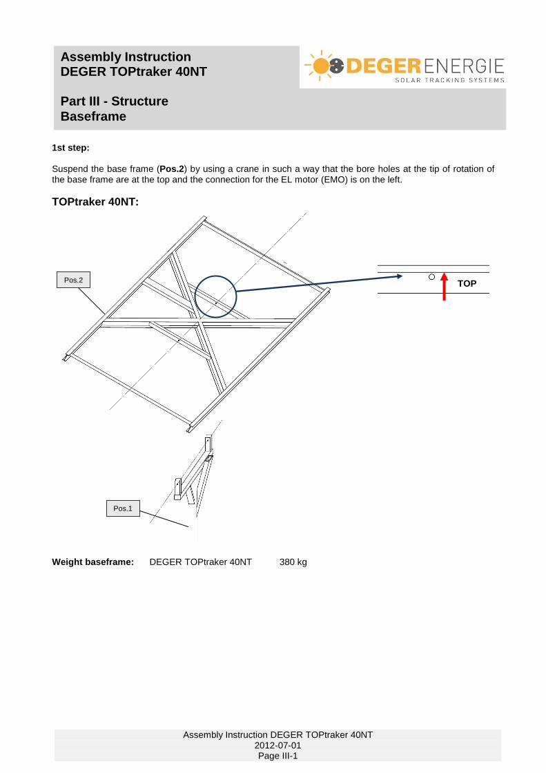
1st step: Suspend the base frame (Pos.2) by using a crane in such a way that the bore holes at the tip of rotation of the base frame are at the top and the connection for the EL motor (EMO) is on the left.
TOPtraker 40NT: Weight baseframe: DEGER TOPtraker 40NT 380 kg
TOP
Pos.1
Pos.2

Assembly Instruction DEGER TOPtraker 40NT Part III - Structure
Baseframe
Assembly Instruction DEGER TOPtraker 40NT 2012-07-01 Page III-2
2nd Step: Upper suspension: (see drawing below) Install M24x180 bolts (Pos. 7) from above with M24 washers (Pos. 9) and M24 nuts (Pos. 8). Two bearing discs (Pos. 10) are to be installed between lower cover plate and supporting frame! Do not tighten bolts too far to avoid compressing cover plates. 3rd Step: Lower suspension: Install M24x180 bolts (Pos. 7) with M24 washers (Pos. 9) and M24 nuts (Pos. 8). Do not tighten bolts too far to avoid compressing cover plates.
WARNING!! The supporting frame must be suspended freely between the two cover plates on the lower suspension. If necessary, the number of bearing discs at the upper suspension must be varied!! Slide bearing bushings are installed at the rotation point of the base frame – these must be slightly lubricated in the initial installation. Later on lubrication is possible at any time through a lubricating nipple in the bolt M24x180. A list of suitable lubricants you find on page VII-2.
Mounting the modules on the base frame beforehand is not permitted!!
Pos.9 Pos.10 Bearing discs Only at upper suspension!! Nur am oberer Aufhängung!!
Pos.8 + Pos.9
Pos.1
Pos.7 M24x180
free! Bearing discs !
WARNING! No contact between supporting
frame and cover plates!!!!
Bearing discs (Pos. 10) Only at upper suspension!!

Assembly Instruction DEGER TOPtraker 40NT Part III - Structure
Elevation-Motor (EMO)
Assembly Instruction DEGER TOPtraker 40NT 2012-07-01 Page III-3
1st step: Fix Elevation motor (EMO) (Pos. 3) at the base frame (Pos. 2) by using bolt M14x80 (Pos. 4) and nut M14 (Pos. 5)
2nd step: Fix Elevation motor at the mast (Pos.1) by using the spezial screws EMO (Pos.6). Therefore the enclosed thread locking fluid (Pos. 11) has to be used. Tighten the special screws with a torquet of 35 Nm. - Do not use any other screws except those included in the delivery (Pos.6)! - Apply one drop of the locking fluid to the internal thread of the EMO.(see drawing beside) - Ensure that no locking fluid enters into the sliding bearing connector! The EMO is delivered with preseted limit switches so no set up work has to be done at all.
Pos.3
Pos.4 (M14x80)
Pos.2
Pos.5
Pos.6 special-screw EMO Pos.3
Pos.6 special-screw EMO
Pos.1
Warning!! The enclosed BEST-MK 1325 thread locking fluid must be used!!

Assembly Instruction DEGER TOPtraker 40NT Part III - Structure
Elevations-Motor (EMO)
Assembly Instruction DEGER TOPtraker 40NT 2012-07-01 Page III-4
Manual operation: When electrical components fail the systems can be moved into the horizontal position by using a 12V or 24V batterie. When all electrical components fail the systems can be moved into the horizontal position by using standard tools. For this the Aluminium-Cover at the lower side of the elevation motor has to be removed. After this apply a spanner wrench (size 17mm) at the hexagonal nut at the end of the elevation motor and turn slowly (max. 30°/sec ==> 5 Upm) clockwise.
IMPORTANT: Disconnect the Elevation-Motor from the Energy-Converter by loosen clamp 1 and
2 before beginning with this work.
Operating Instructions!! The expansion bellows may not be pinched, blocked or compressed, since this can lead to damage to the internal parts. A mechanical blockage of the movement of the piston rods is to be avoided since this can lead to damage to the drive system. The linear actuator must come to a complete stop before changing the movement direction.
A fast reversal of the travel direction of the actuator is not permitted.
Checking of the mechanics Extend and retract the complete way of the drive, to guarantee that the mechanics moves freely, does not knock against anything and that the cables are long enoungh. Use a 12V or 24V batterie
(for ex. suitable for a batterie-driven drill) for the head of the drive.

Assembly Instruction DEGER TOPtraker 40NT Part IV - Module carry system
DEGER TOPtraker 40NT
Assembly Instruction DEGER TOPtraker 40NT 2012-07-01 Page IV-1
Module arrangement: The following dimensions have to be abode: - Module surface: max. 40m² - length of Module surface: max. 8,30m - height of Module surface: max. 5,30m The total module area is to be determined relative to the site with the aid of the DEGERenergie dimensioning tool and may in no case be greater than 40m².
Illustration shows 0°-version -
1st step: Arrangement of aluminium profiles: Following points have to be attended: - in both axels modules have to be arranged symmetrically to the center of gravity - 2 aluminium profiles for each row of modules - attend the connecting socket on the backside of the modules Distance between 2 aluminium
profiles :x = width of module / 2
Overhang of the aluminium profile: y = (length of aluminium profile - 2.60m) / 2
In the range of the suspension for the elevation motor it is not possible to assemble the MTH-clamps at the outside of the base frame. Here the MTH-clamps have to be assembled at the inside of the base frame.
Outside Inside
Base frame 7,20m
Length of module surface max. 8,30m
Base f
ram
e 2
,60
m
Heig
ht of
mod
ule
surf
ace m
ax.
5,3
0m
Alu-profile

Assembly Instruction DEGER TOPtraker 40NT Part IV - Module carry system
Assembly aluminium profiles and modules
Assembly Instruction DEGER TOPtraker 40NT 2012-07-01 Page IV-2
2nd step: Assembly of aluminium profiles: Assemble aluminium profile (Pos. 12) on both sides at the outside of the base frame (Pos. 2) by using clamp MTH-clamp M10 (Pos. 13), bolt M 10 x 35 (Pos. 15), Lock-Washer-M10 (Pos. 22), and sliding nut M10 (Pos. 14) torque: 35NM The clamp MTH has to be slided inside the aluminium profile towards the base frame until the bolt contacts the base frame. Between the modules Assemble modules on the aluminium profiles (Pos.12) by using bolt M6 (Pos. 20), Lock-Washer-M6 (Pos. 24), clamp plate (Pos. 19) and sliding nut M6 (Pos. 21) At the end of the module-surface Assemble modules on the alumnium profiles (Pos.12) by using clamp MTH M8 (Pos. 16), Lock-Washer-M8 (Pos. 23), bolt M8x30 (Pos. 18) and sliding nut M8 (Pos. 17) torque: 18NM
ATTENTION: Extend and retract the complete way of the drive, to guarantee that the mechanics move freely, don't knock against anything and that the cables are long enoungh.
It is necessary that the locking ring (Pos. 24) be installed
between bolt (Pos. 20) and center plate (Pos. 19)!
It is necessary that the locking ring (Pos. 23) be installed
between bolt (Pos. 18) and MTH clamp (Pos. 16)!
WARNING!! We strongly recommend that a gap of approximately 2 mm be left between the individual module rows.
Pos.2
Pos.12
Pos. 15 (M10 x35) + Pos. 14
Pos.13
Pos.22
Pos. 20 (M6) + Pos. 21
Pos.19
Pos.24
Pos.12
Pos. 18 (M8x30) + Pos. 17
Pos.16 Pos.12
Pos.23
It is necessary that the locking ring (Pos. 22) be installed
between bolt (Pos. 15) and MTH clamp (Pos. 13)!

Assembly Instruction DEGER TOPtraker 40NT Part IV - Module carry system
Assembly aluminium profiles and modules
Assembly Instruction DEGER TOPtraker 40NT 2012-07-01 Page IV-3
It is necessary that all bolts of the module attachment are provided with the corresponding locking ring to ensure against self-loosening. The bolts have to be assembled with a sliding nut as shown beside. The sliding nuts have to be mounted in that way the side with the sharp, not rounded angles is pressed against the Aluminium profile. Tip:
Bring the DEGERtraker in a horizontal position - then it will be easier to mount the modules
Lock-Washer Pos. 22, 23 and 24
Sliding nut Pos. 14, 17 and 21 Schiebemutter
WARNING! The total module area is to be determined relative to the site with the aid of the DEGERenergie dimensioning tool and may in no case exceed the maximum allowable total module surface. Maximum total module surface
DEGER TOPtraker 40NT: 40m² Defects resulting from a too large module surface are not covered by the warranty. Because the elevation motor is not completely self-locking, it is possible that the module surface can move into another position in strong winds. In order to avoid this situation, the motor connections should be kept short. It is recommended that the module surface position be inspected on a daily basis until commissioning is finalized!
Assembly of the modules is permitted only on the already-assembled base frame.
Module assembly beforehand is not permitted.

Assembly Instruction DEGER TOPtraker 40NT Part V - Control unit
Assembly control unit
Assembly Instruction DEGER TOPtraker 40NT 2012-07-01 Page V-1
The installation of the DEGER TOPtraker may only be conducted by suitable specialists! We recommend that the system be inspected by a master electrician, or at least a person with equivalent qualification, after completion. The Startup Protocol is to be used for this, filled out and sent to DEGERenergie. 1st step: Fixing energy converter Fix the energy converter (Pos.25) on the mast (Pos.1) by using the provided mounting plate and hose clamps. 2nd step: Controlling of the axis
Mount the DEGERconecter (Pos. 26) pointing UPWARDS above the solar module surface. Connect the cable of the motor Blue cable connection 1 Brown cable connection 2 Special attention has to be paid to the datasheet of the Energy converter on page V-II.
Pos.25
Pos.26
Function test: Check if the drive rotates the module surface towards the brightest spot in the sky. If you are not sure, you can cover a sensor cell at the DEGERconecter with your hand – now the module surface should rotate in the direction of the non-covered sensor cell. Otherwise change connection 3 / 4
Assembly Instruction DEGER TOPtraker 40NT Part V - Control unit
Functional characteristics
Assembly Instruction DEGER TOPtraker 40NT 2012-07-01 Page V-2
A technology to rely on. The fact that the patent-protected control system were awarded the inventor’s prize of the federal state of Baden-Württemberg in South-Germany in 2000 shows that the DEGERtraker meets the demands of both experts and investors. Functioning The DEGERconecter control unit detects the brightest spot in the sky and adjusts the module surface’s position to face it. The DEGERtraker’s mechanical system allows the accurate adjustment of the module surface to the sun all year round. This technology also works in cloudy, rainy or foggy conditions. If, for example, a day starts off sunny with clouds moving in from the west in the afternoon, the module surface will then move back slightly towards the east. On a completely overcast day, the module surface is adjusted to a horizontal position, or to face the point of the strongest irradiation. This allows to make the most out of adverse weather conditions. The control unit is designed to work preferably efficiently and only to do activities that cause a direct increment of the solar yield. In particular the system doesn`t move east globally at night but does this with the sunrise in the morning.

Assembly Instruction DEGER TOPtraker 40NT Part V - Control unit
Datasheet energy converter II - TOPtraker
Assembly Instruction DEGER TOPtraker 40NT 2012-07-01 Page V-3
Power supply of the DEGERconecter and the drive The use of the DEGER TOPtraker with Energiekonverter II – TOPtraker is permissible for the following environmental conditions: Site altitude above MSL: max. 2000m Allowable environment temperature: -20°C to +55°C

Assembly Instruction DEGER TOPtraker 40NT Part VI - Certificates
Declaration of conformity
Assembly Instruction DEGER TOPtraker 40NT 2012-07-01 Page VI-1
Declaration of Conformity in accordance with EC machine directive 2006/42/EG, addendum II A
for solar tracking systems
We,
DEGERenergie GmbH, 72160 Horb a.N., Germany herewith declare that the listed products in the way we put them in circulation destined for EC member countries are fitted with CE plates in accordance with EC machine directive.
Note: This declaration will become invalid if the product is - modified, supplemented or changed in any kind - and/or accessories not from DEGERenergie are used - and in case of inappropriate assembling or installation or not intended use/improper use without our express permission
marking of the systems: DEGER TOPtraker 8.5 DEGER TOPtraker 25HD DEGER TOPtraker 40NT EC-directives: EC machine directive (2006/42/EC) EC Low Voltage Directive 73/23/EEC)
EC EMV directive (89/336/EWG) i.d.F. 93/31/EWG Applied harmonised standards: EN 61000-6-2:2005
EN 55011:1998 Applied national standards DIN 42025: and technical specification DIN 1045-1: 2007-08 DIN 1055-1: 2002-06 DIN 1055-4: 2005-03 DIN 18800: 1990-11
DIN 4149: 2005-04 Horb, 09.03.2009
DEGERenergieGmbH , Artur Deger - General Manager –

Assembly Instruction DEGER TOPtraker 40NT Part VI - Certificates
TÜV-Certificate
Assembly Instruction DEGER TOPtraker 40NT 2012-07-01 Page VI-2

Assembly Instruction DEGER TOPtraker 40NT Part VI - Certificates
Declaration of commitment
Assembly Instruction DEGER TOPtraker 40NT 2012-07-01 Page VI-3
DEGERtracker 3000NT, 5000NT, 6000NT, 7000NT, 9000NT, 3000HD, 5000HD, D60H, D80, D100 TOPtracker 8.5, TOPtracker 40NT
You have purchased a product that was subject to meticulous examination before it was delivered. Nevertheless, in the event that the DEGERtracker supplied by us does display any defects then the scope of our liability for defects shall be as follows (valid from 1
st December 2013):
Liability for defects
DEGERenergie GmbH grants a 2-year period for any claims for defects to be asserted. This period starts with the delivery from the factory. DEGERenergie GmbH offers to replace the defective parts free of charge where any justified claims are received in this period.
In addition, DEGERenergie GmbH offers a lump sum as compensation for outlays for transportation and labor where defective parts are replaced. An up-to-date list of these one-off lump sums is available upon request. Actual costs may vary through the location and design of the systems and cannot therefore be taken into account. In all other respects the General Terms and Conditions for deliveries and services shall additionally apply in this regard: version: December 2013
For the entire steel construction DEGERenergie GmbH offers extended liability for defects of 20 years against rust-through starting with the delivery from the factory. Where a defect arises the contract partner of DEGERenergie GmbH is obligated to inform DEGERenergie GmbH immediately by sending a fault report (part of the assembly instructions) by fax to: +49 (0)7451 539 1410 or by e-mail to: [email protected], stating the system serial number.
Proof
A fault report completed in full and stating the system serial number is considered as proof with any claim for defects (see Liability for defects). The defective assembly part must be sent to DEGERenergie GmbH for examination with a copy of the fault report. The type plate on the equipment must be completely legible. There must be no changes present or made to the original delivery condition and no mechanical damage (cut cables, damaged terminals, etc.). An invoice must be submitted with a copy of the fault report in order to claim the lump-sum payment. DEGERenergie GmbH will decide on its liability for defects as well as the lump-sum payment following an examination of the assembly part sent.
Terms and conditions
Once the spare part is received, the damaged part must be returned to DEGERenergie GmbH in its original packaging or at least in equivalent transport packaging. A return slip will be enclosed with the spare part. Where there is a defect in the contractual item and DEGERenergie GmbH is responsible for this, then DEGERenergie GmbH shall be under an obligation to repair the damaged part or replace it with a spare part, unless DEGERenergie GmbH is entitled to refuse the supplementary performance on account of statutory regulations. Any replacement of individual parts within the defect period does not give rise to an extension to the validity period neither for the liability for defects in the system nor for the replaced spare part. The contract partner of DEGERenergie GmbH must grant the latter a reasonable period for the supplementary performance. DEGERtracker that are standardized with a wind guard are only allowed to be operated in association with a suitable wind guard which brings the solar module area into the horizontal position in the event of a storm. This must be assembled in accordance with the specifications in the assembly instructions. It must be ensured that this wind guard is available and fully functional at all times.
Liability Disclaimer
DEGERenergie GmbH is not liable for any damage that arises as a consequence of improper operation by the contract partner, in particular if the module area is dimensioned too generously. The maximum module area that can be installed can be seen in the module layout plan sent with the order confirmation from DEGERenergie GmbH. Where permissible under the law then DEGERenergie GmbH shall not be liable for material damage and financial loss (e.g. lost buyback price) which result from a defect in the tracking system. Open area systems: Under the provision under "Liability for defects", DEGERenergie GmbH is not liable for any extra costs (e.g. use of crane, skylift , etc.) that arise from using higher masts than the standard version. Building integration: Under the provision under "Liability for defects", DEGERenergie GmbH is not liable in particular for any extra costs (e.g. use of crane, skylift, etc.) that arise from erecting masts on buildings. In addition DEGERenergie GmbH is not liable for:
- defects that arise from unintended use - defects that arise from the use of third-party components, e.g. the mounting profile - defects that arise through changes to the mechanics and/or electronics - defects that arise on account of a force majeure event (lightning strikes, surges, severe storm, fire, etc.) - defects that arise through the module area being too large in derogation from the module layout plan (depending on the installation
location, installation height, etc.) - defects that arise through interventions, changes or repair attempts that have been made - defects that arise through a failure to follow the information in the assembly and operating manual.
In all other respects our General Terms and Conditions for deliveries and services shall additionally apply, version: December 2013 The German version of this declaration is legally binding. Translations into other languages serve only for a better comprehension.

Assembly Instruction DEGER TOPtraker 40NT Part VII - Troubleshooting / Maintenance
Troubleshooting
Assembly Instruction DEGER TOPtraker 40NT 2012-07-01 Page VII-1
Pos.4 (M14x80)
5100
023
5100
002
4100
036
4100
038
5100
023

Assembly Instruction DEGER TOPtraker 40NT Part VII - Troubleshooting / Maintenance
Maintenance
Assembly Instruction DEGER TOPtraker 40NT 2012-07-01 Page VII-2
The DEGER TOPtraker 40NT is basically designed and constructed so that as little service and maintenance work as possible is incurred. The following work must be conducted annually for a safe and durable operation. Service work may only be conducted by qualified specialists.
A. Grease Supporting Frame Pivot The plain bearing bushings of the supporting frame should be greased by the lubricating nipples of the M24 bolts on the frame carrier. For this, introduce grease with the aid of a commercially-available grease gun until this exits from the forth from the bearings. bothsides
B. Grease Bearings of the Elevation Motor (EMO) DEGERenergie likewise recommends greasing the bearing arrangement of the elevation motor annually with the aid of commercially-available spray lubricant (for example Multilupe).
Assembly Instruction DEGER TOPtraker 40NT Part VII - Troubleshooting / Maintenance
Maintenance
Assembly Instruction DEGER TOPtraker 40NT 2012-07-01 Page VII-3
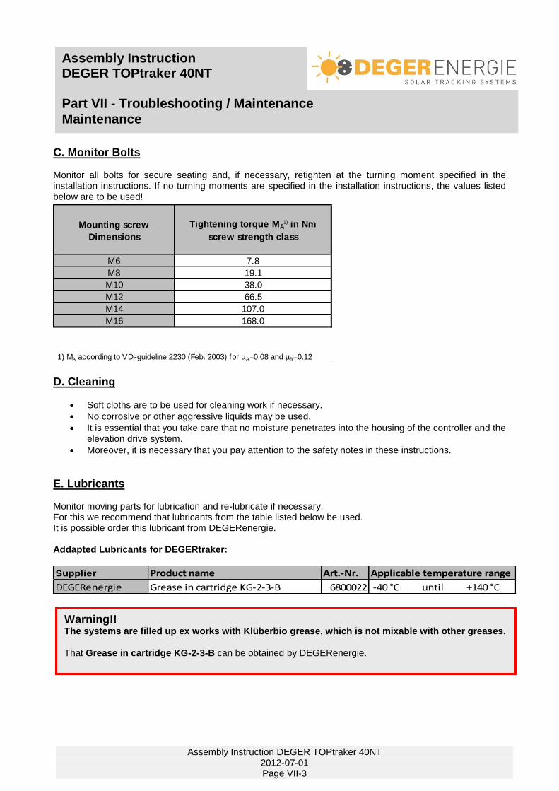
C. Monitor Bolts Monitor all bolts for secure seating and, if necessary, retighten at the turning moment specified in the installation instructions. If no turning moments are specified in the installation instructions, the values listed below are to be used!
D. Cleaning
Soft cloths are to be used for cleaning work if necessary.
No corrosive or other aggressive liquids may be used.
It is essential that you take care that no moisture penetrates into the housing of the controller and the elevation drive system.
Moreover, it is necessary that you pay attention to the safety notes in these instructions.
E. Lubricants Monitor moving parts for lubrication and re-lubricate if necessary. For this we recommend that lubricants from the table listed below be used. It is possible order this lubricant from DEGERenergie. Addapted Lubricants for DEGERtraker:
Supplier Product name Art.-Nr. Applicable temperature range
DEGERenergie Grease in cartridge KG-2-3-B 6800022 -40 °C until +140 °C
Mounting screw
Dimensions
Tightening torque MA1) in Nm
screw strength class
M6 7.8
M8 19.1
M10 38.0
M12 66.5
M14 107.0
M16 168.0
1) MA according to VDI-guideline 2230 (Feb. 2003) for µA=0.08 and µB=0.12
Warning!! The systems are filled up ex works with Klüberbio grease, which is not mixable with other greases.
That Grease in cartridge KG-2-3-B can be obtained by DEGERenergie.

Report of implementing DEGER TOPtraker 40NT
Assembly Instruction DEGER TOPtraker 40NT 2012-07-01 Page VIII-1
Type: • DEGER TOPtraker 8.5-20° • DEGER TOPtraker 8.5-30°
• DEGER TOPtraker 40NT (Please fill in using capital letters so it is easily legible!!)
Operator: Installer/Planer: Name: _______________________________ Name: _______________________________
Address: _______________________________ Address: _______________________________
Telephone:_______________________________ Telephone:_______________________________
Delivery date: ______________________________
Delivery note number: ______________________________ Please also attach a copy of the delivery note!!! Date of implementing: ______________________________
Name of the solar park: ______________________________
Number of systems: ______________________________
Serial number: (Tracker) ______________________________ (please mention complete serial number)
Assembly:
• free standing traker • traker integrated in building
• with foundation
Implementing
V
A
Measured data
power supply
current consumption motor
Contol of the function
modulesurface rotates towards the brightest spot
dimensions of module arrangement are abode
lightning protection and grounding is connected
conecter is mounted pointed upwards above the solar module surface
locking fluid EL-motor is applied
Control of the assembly
reinforcement of the foundation was build in due to the plan
hole sphere of action is free of objects
mechanic moves freely, cables are long enough
cable connection of the EL-motor on the lower side
Date: ______________________________
Signature: ______________________________ Signature: ______________________________ (Operator) (Installer/Planer)
IMPORTANT INSTRUCTIONS! The commissioning protocol must be filled in when the system is first commissioned, and faxed within 4 weeks of commissioning (at the latest 3 months after delivery) to DEGERenergie GmbH
+49 7451 5391410 or sent by e-mail to [email protected].
The protocol is ready for download at www.degerenergie.com!

Assembly Instruction DEGER TOPtraker 40NT Part VIII - Protocols
List of tracking systems
Assembly Instruction DEGER TOPtraker 40NT 2012-07-01 Page VIII-2
No. Position Serial-No. No. Position Serial-No. No. Position Serial-No.

Protocols – Fault report
DEGER TOPtraker 40NT
Assembly Instruction DEGER TOPtraker 40NT 2012-07-01 Page VIII-3
To assist in case of problems with our systems it is necessary to have this fault report on hand. Without a completely filled out fault report there cannot be any support provided!!
Please send this report to the following fax number: +49 7451 5391410 or scan and email to: [email protected] Please provide a phone number to contact you.
RECALL-NUMBER: ________________________ (required)
Fault report from ___.___.______

Assembly Instruction DEGER TOPtraker 40NT Part VIII - Protocols
Company adress
Assembly Instruction DEGER TOPtraker 40NT 2012-07-01 Page VIII-4
DEGERenergie GmbH Industriestrasse 70 D-72160 Horb am Neckar Germany Tel: +49 (0) 7451-53914-0 Fax: +49 (0) 7451-53914-10
email: [email protected] www.degerenergie.com