assembly instructions for first mate - cloud object storage · mast - round or octagonal section -...
TRANSCRIPT

58
64
68
72
73
73
55
3816
553
553
553
553
553
653
400
73
Mast - Round or Octagonal section - hollow or solid on taper shown.
Hollow mast is best made using the "Bird's Mouth"method, and must include a solid plug in both heeland tip. The heel plug needs to extend above the partners (i.e. deck level) and should finish with an internal v-shaped cut out to prevent an abrupt changein stiffness. Tip plug approximately 100mm long.Blue numbers in brackets refer to the width of a Bird's Mouth stave of 16.3mm thickness. This will yeild a hollow mast with a minimum wall thickness of 20%.Extend as shown in blue dotted lines and plane to the drawn taper after the solid base plug has been glued into position.
32
52
39
4050
Top
Heel of Sprit
675
675
675
675
675
675
42
49
51
47
Sprit - Round or Octagonal section - hollow or solidon taper shown.
Hollow sprit best made using the "Bird's Mouth" method.Plug heel and tip of hollow sprit with plug approximately 100mm long.
260046
33
40
46
43
25 207
R 40
650
650
650
650
Boom - Jaws from 25mm hardwoodwith leather padding. Boom may beround, octagonal, or square on taper shown.See full-sized drawing of jaws sheet 26-A3(Boom recommended for general use, but sheeting geometry allows for change betweenboomed or boomless configuration at will)
Sheet attached toblock running on bridle through existingfairleads.
2.1 sq.m23 sq.ft
7.54 sq.m81 sq.ft
9.64 sq.m104 sq.ft
This design remains the property ofRoss Lillistone.All rights reserved. Purchase of plans fromthe designer authorises the building of one boatto this design.
(SeeSpar Details sheet for informationregarding running rigging and ends ofspars)
First Mate - Sprit-Sloop RigScale 1:20
(22.1)
(24.6)
(26.2)
(27.8)
(28.3)
(28.3)
(28.3)
(28.3)
76 sq.ft7.10 sq.m
3492
582
582
582
582
582
582
34
44
51
55
55
52
45
Heel of Yard
Peak of Yard
2912
728
728
728
728
42
50
52
48
37
Heel of Boom
Peak of Boom58
64
68
72
73
73
73
55
500
3816
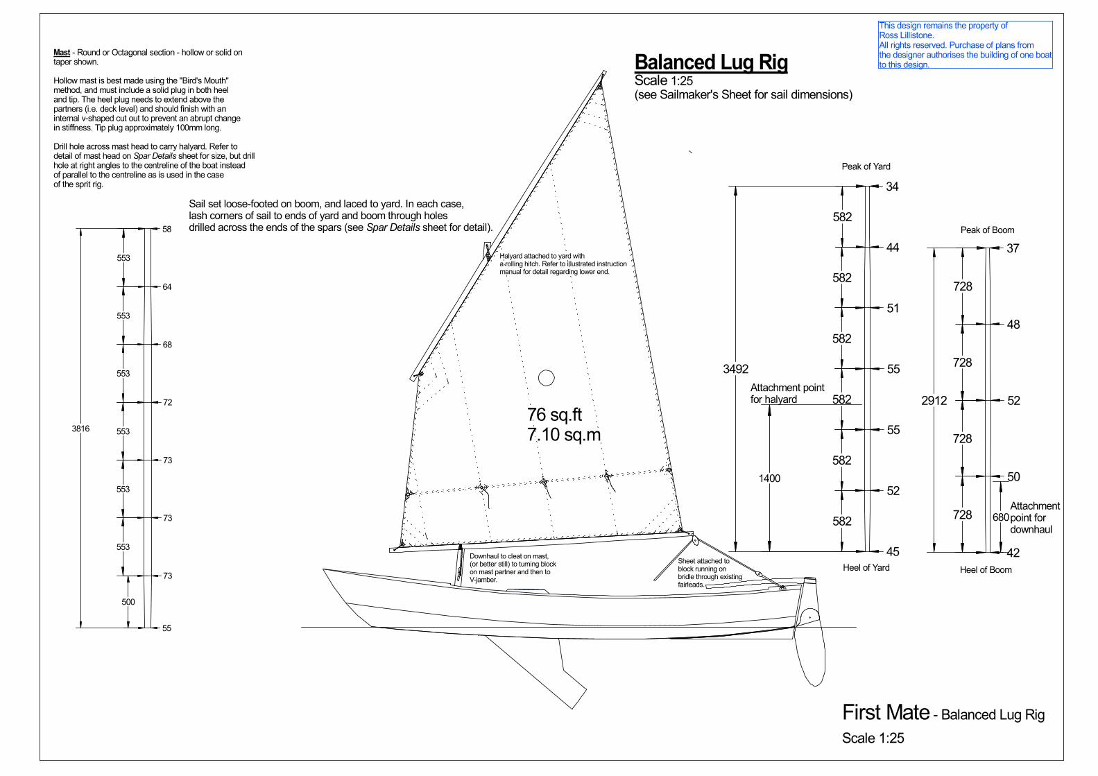
Mast - Round or Octagonal section - hollow or solid on taper shown.
Hollow mast is best made using the "Bird's Mouth"method, and must include a solid plug in both heeland tip. The heel plug needs to extend above the partners (i.e. deck level) and should finish with an internal v-shaped cut out to prevent an abrupt changein stiffness. Tip plug approximately 100mm long.
Drill hole across mast head to carry halyard. Refer todetail of mast head on Spar Details sheet for size, but drill hole at right angles to the centreline of the boat instead of parallel to the centreline as is used in the case of the sprit rig.
553
553
553
553
553
553
Balanced Lug RigScale 1:25 (see Sailmaker's Sheet for sail dimensions)
1400
Attachment pointfor halyard
680Attachment point for downhaul
Downhaul to cleat on mast,(or better still) to turning blockon mast partner and then to V-jamber.
Halyard attached to yard witha rolling hitch. Refer to illustrated instructionmanual for detail regarding lower end.
Sheet attached toblock running on bridle through existingfairleads.
This design remains the property ofRoss Lillistone.All rights reserved. Purchase of plans fromthe designer authorises the building of one boatto this design.
Sail set loose-footed on boom, and laced to yard. In each case,lash corners of sail to ends of yard and boom through holesdrilled across the ends of the spars (see Spar Details sheet for detail).
First Mate - Balanced Lug RigScale 1:25

22 sq.ft
67 sq.ft
38
55
65
71
73
73
55
873
873
1100
1100
1100
500
5546
38
46
46
36
400
400
2830
1015
1015
50
Boom - Jaws from 25mm hardwoodwith leather padding. Boom may beround, octagonal, or square on taper shown.See full-sized pattern on Boom Jaw sheet.See sheet Spar Detail sheet for sail attachment detail
R 39
203
25
Attach Shrouds and Forestayat this position using commercialHound such as Riley RM77/RM89or RonstanRF604/RF347 or similar.
Shrouds and Forestay from 1/8" 1 x 19Stainless Steel wire (or larger). 1/8"provides adequate safety margin.
3800
89 sq.ft8.29 sq.m
Bermudian Sloop RigScale 1:25(see Sailmaker's Sheet for sail dimensions)
1
2
3
4
56
Mast may be made hollow or solid to diameters noted on drawing. If hollow, I recommend the'Bird's Mouth' method, with a solid insert from the heel extending 1000mm upwards to takeloads from the partners and the boom jaws. Also place a solid insert in the region of the stay and shroud attachment point (hounds). Make this insert about 350mm long.
Sail may be set in luff groove, or commercially-made track.
1. Chainplates such as Ronstan RF488. Attach to hullusing 316 Stainless Steel bolts. Glue reinforcing doublerto inside face of planking to distribute laods into hull and deck.Shape doubler to suit hull and deck - Approximate dimensions140mm x 75mm x 19mm. Location shown should be close toa deck knee, to which the block can also be glued. Position 1825mm aft of face of stem, measured with a tape i.e. markedon the deck as a radius centred on the top of the face of the stem. The chainplates are on the outside of the planking, protruding through a slot cut in the gunwales and deck.
2. Jib sheet fairleads positioned approximately 593mm aftof chainplate, measured along deck. Location will have to beadjusted to suit set of sails. Fairleads mounted on adjustabletrack are ideal.
3. Forestay attached to pad eye bolted through deck andkingplank, or to a chainplate bolted to face of stem.
4. Commercial hound and tangs such as Ronstan RF604/RF347, or Riley RM77/RM89.
5. Mainsheet. Attach bridle through fairleads used for standard rig,(see Spar Detail sheet). Suggestion only - many different sheetingarrangements may be used. See illustrated instruction manual.
6. Commercial Goose Neck such as Riley RM84/RM103, orwooden jaws as shown on boom drawing below and Boom Jaw sheet
This design remains the property ofRoss Lillistone.All rights reserved. Purchase of plans fromthe designer authorises the building of one boatto this design.
First Mate - Bermudian Sloop Rig
Scale 1:25
This design remains the property ofRoss Lillistone.All rights reserved. Purchase of plans fromthe designer authorises the building of one boatto this design.
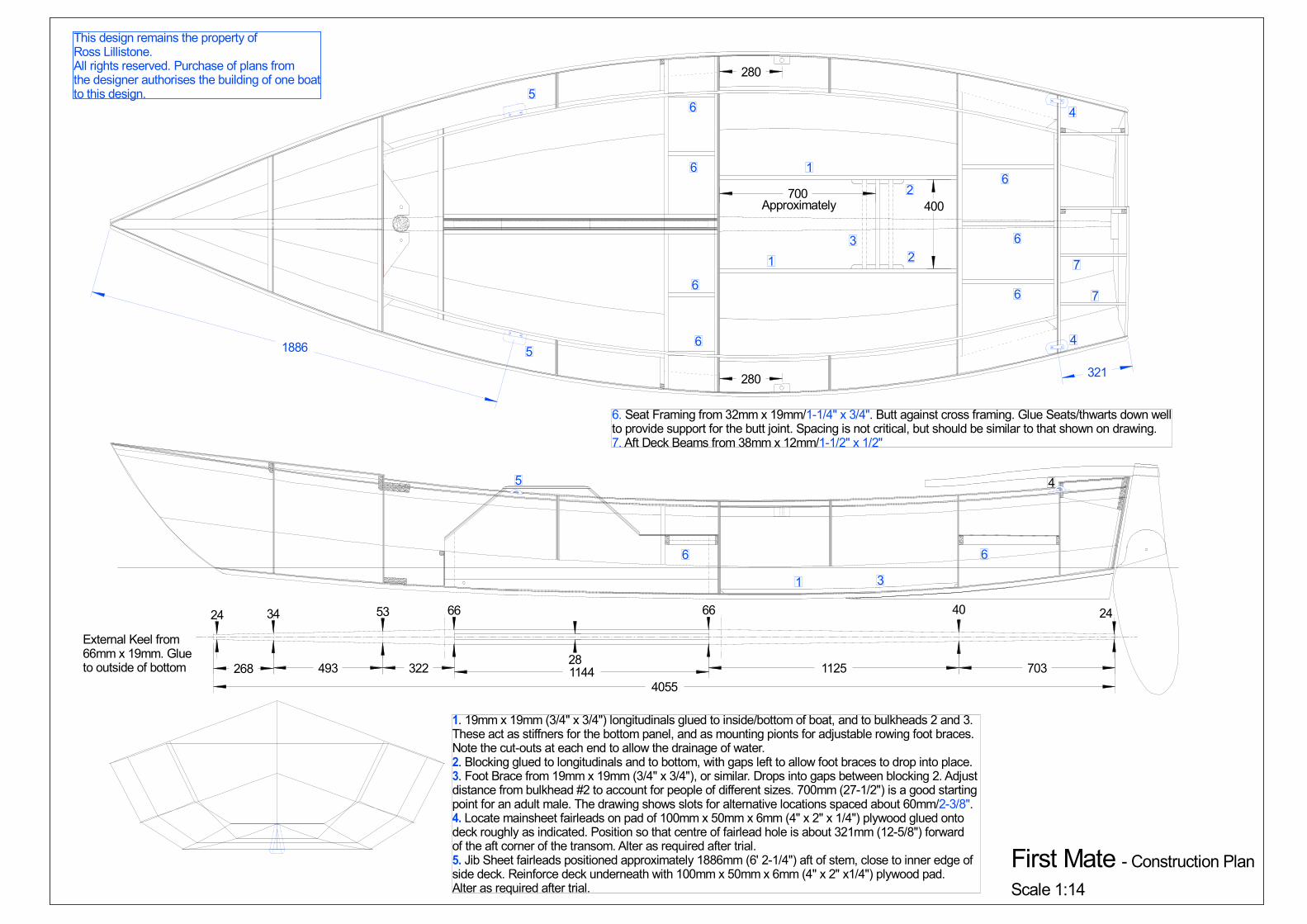
First Mate - Construction PlanScale 1:14
24 34 53 66 66 40 24
4055
External Keel from66mm x 19mm. Glueto outside of bottom
28
280
280
700
1
1
2
2
3
1
Approximately
3
1. 19mm x 19mm (3/4" x 3/4") longitudinals glued to inside/bottom of boat, and to bulkheads 2 and 3.These act as stiffners for the bottom panel, and as mounting pionts for adjustable rowing foot braces.Note the cut-outs at each end to allow the drainage of water.2. Blocking glued to longitudinals and to bottom, with gaps left to allow foot braces to drop into place.3. Foot Brace from 19mm x 19mm (3/4" x 3/4"), or similar. Drops into gaps between blocking 2. Adjustdistance from bulkhead #2 to account for people of different sizes. 700mm (27-1/2") is a good starting point for an adult male. The drawing shows slots for alternative locations spaced about 60mm/2-3/8".4. Locate mainsheet fairleads on pad of 100mm x 50mm x 6mm (4" x 2" x 1/4") plywood glued ontodeck roughly as indicated. Position so that centre of fairlead hole is about 321mm (12-5/8") forward of the aft corner of the transom. Alter as required after trial.5. Jib Sheet fairleads positioned approximately 1886mm (6' 2-1/4") aft of stem, close to inner edge ofside deck. Reinforce deck underneath with 100mm x 50mm x 6mm (4" x 2" x1/4") plywood pad.Alter as required after trial.
400
268 493 322 1144 1125 703
321
4
4
4
1886 5
5
5
6
6
6
6
6
6
6
6. Seat Framing from 32mm x 19mm/1-1/4" x 3/4". Butt against cross framing. Glue Seats/thwarts down wellto provide support for the butt joint. Spacing is not critical, but should be similar to that shown on drawing. 7. Aft Deck Beams from 38mm x 12mm/1-1/2" x 1/2"
7
7
66

This design remains the property ofRoss Lillistone, Esk, QLD, AUSTRALIA.All rights reserved. Purchase of plans fromthe designer authorises the building of one boatto this design.
166
24
751
388
123
265
5050
50
50
First Mate - Midships WebframeScale 5:1
130
Midships Webframe cut from 12mm marine plywood, to outline shown in blue. Glue 38mm x 12mm crossbeam tofor'd face of frame as shown by black hidden detail lines. Cut out openings approximately as shown, but ensure that the perimeter of the frame remains at least 50mm wide. Round-out the corners of the cutouts well to preventstress concentrations. Position webframe so that for'd face of plywood lines up with frame position line on inside of hull. Centreboard case is glued and screwed to forward face of webframe. Notch out the upper, aft corner of the case to accomodate the crossbeam.
421
614
50
20
40
20
1365
200 200
Ends of longitudinal foot-brace supports whichare glued in after assembly of the hull. No needto cut out notches, as the supports just butt up against the frame. See Construction Plan.
244
268
138
53
66
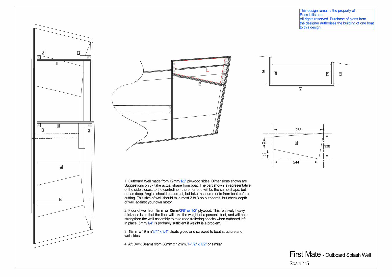
First Mate - Outboard Splash Well
Scale 1:5
1. Outboard Well made from 12mm/1/2" plywood sides. Dimensions shown areSuggestions only - take actual shape from boat. The part shown is representativeof the side closest to the centreline - the other one will be the same shape, but not as deep. Angles should be correct, but take measurements from boat before cutting. This size of well should take most 2 to 3 hp outboards, but check depth of well against your own motor.
2. Floor of well from 9mm or 12mm/3/8" or 1/2" plywood. This relatively heavythickness is so that the floor will take the weight of a person's foot, and will helpstrengthen the well assembly to take road trailering shocks when outboard leftin place. 6mm/1/4" is probably sufficient if weight is a problem.
3. 19mm x 19mm/3/4" x 3/4" cleats glued and screwed to boat structure andwell sides.
4. Aft Deck Beams from 38mm x 12mm /1-1/2" x 1/2" or similar
1
1
1
1
2
33
3 3
1 1
2
33
This design remains the property ofRoss Lillistone.All rights reserved. Purchase of plans fromthe designer authorises the building of one boatto this design.
4
4
This design remains the property ofRoss Lillistone, Esk, QLD, AUSTRALIA.All rights reserved. Purchase of plans fromthe designer authorises the building of one boatto this design.
260
7
288
438
219
436
177
402
135
371
97
340
64
309
37
281
22
260
16
248
21
247
38
261
67
286
107
321
156
364
213
412
254
443
93
117
10
461
461
135
5
79
380
72
379
64
369
57
359
50
350
43
343
38
337
34
333
33
332
34
333
38
337
45
344
54
353
65
363
78
375
92
387
104
394
60
111
427371
316249
210
409428410378332
275211
143
71
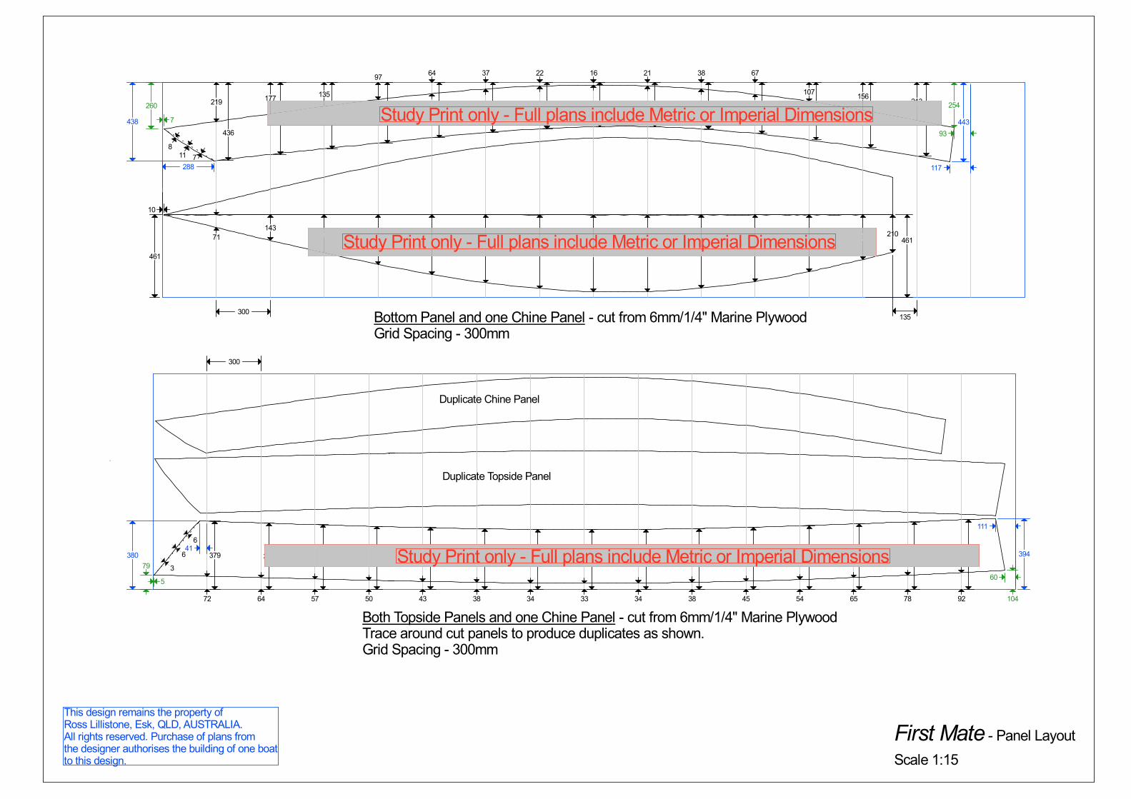
Duplicate Chine Panel
Duplicate Topside Panel
Bottom Panel and one Chine Panel - cut from 6mm/1/4" Marine PlywoodGrid Spacing - 300mm
Both Topside Panels and one Chine Panel - cut from 6mm/1/4" Marine PlywoodTrace around cut panels to produce duplicates as shown.Grid Spacing - 300mm
First Mate - Panel Layout
Scale 1:15
300
300
811 7
6
6
3
41
Study Print only - Full plans include Metric or Imperial Dimensions
Study Print only - Full plans include Metric or Imperial Dimensions
Study Print only - Full plans include Metric or Imperial Dimensions
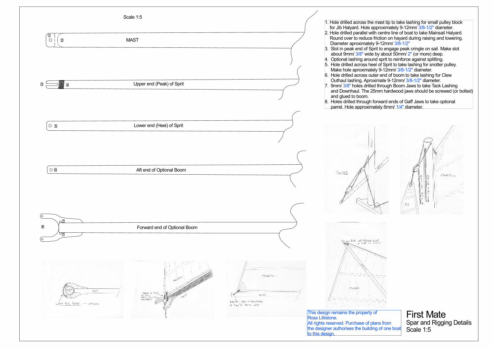
MAST
Upper end (Peak) of Sprit
Lower end (Heel) of Sprit
Aft end of Optional Boom
Forward end of Optional Boom
1
2
3 4
5
6
7
7
8
1. Hole drilled across the mast tip to take lashing for small pulley block for Jib Halyard. Hole approximately 9-12mm/ 3/8-1/2" diameter.2. Hole drilled parallel with centre line of boat to take Mainsail Halyard. Round over to reduce friction on hayard during raising and lowering. Diameter aproximately 9-12mm/ 3/8-1/2"3. Slot in peak end of Sprit to engage peak cringle on sail. Make slot about 9mm/ 3/8" wide by about 50mm/ 2" (or more) deep.4. Optional lashing around sprit to reinforce against splitting.5. Hole drilled across heel of Sprit to take lashing for snotter pulley. Make hole aproximately 9-12mm/ 3/8-1/2" diameter.6. Hole drilled across outer end of boom to take lashing for Clew Outhaul lashing. Aproximate 9-12mm/ 3/8-1/2" diameter.7. 9mm/ 3/8" holes drilled through Boom Jaws to take Tack Lashing and Downhaul. The 25mm hardwood jaws should be screwed (or bolted) and glued to boom.8. Holes drilled through forward ends of Gaff Jaws to take optional parrel. Hole approximately 6mm/ 1/4" diameter.
First MateSpar and Rigging DetailsScale 1:5
Scale 1:5
This design remains the property ofRoss Lillistone.All rights reserved. Purchase of plans fromthe designer authorises the building of one boatto this design.
13
large fillet. This is because large
volumes of epoxy with a small surface
are can build up heat rapidly during the
curing chemical reaction. If doing it in a
number of smaller runs, allow about an
hour between each run – that way you
will still get a chemical bond between
each application, but the majority of the
heat from the exothermic reactions will
dissipate before the next lot goes into
place.
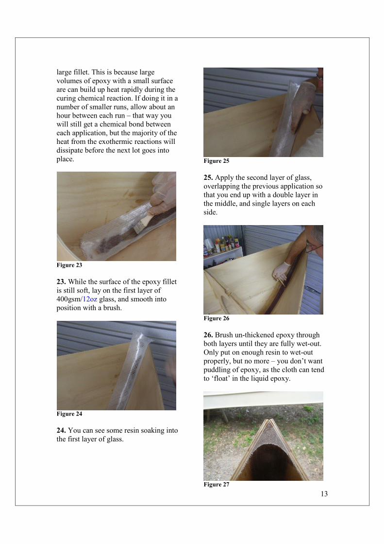
Figure 23
23. While the surface of the epoxy fillet
is still soft, lay on the first layer of
400gsm/12oz glass, and smooth into
position with a brush.
Figure 24
24. You can see some resin soaking into
the first layer of glass.
Figure 25
25. Apply the second layer of glass,
overlapping the previous application so
that you end up with a double layer in
the middle, and single layers on each
side.
Figure 26
26. Brush un-thickened epoxy through
both layers until they are fully wet-out.
Only put on enough resin to wet-out
properly, but no more – you don’t want
puddling of epoxy, as the cloth can tend
to ‘float’ in the liquid epoxy.
Figure 27