assembly instructions - it works! - palfinger
TRANSCRIPT

Assembly instructions
for
MBB Tail Lift Standard


Assembly instructions
forMBB Tail Lift
Standard
07-500.99-04.10-03 19.03.2013
Ref. no.: 2032342 A 20956


5
1 About these instructions ............................................... 7
1.1 Abbreviations used ................................................................... 7
1.2 Enclosed documents ................................................................ 7
2 Important safety information ........................................ 9
2.1 Personnel qualifications ............................................................ 9
2.2 Warning notices in these assembly instructions ..................... 10
2.3 You must take these points into account during installation ... 11
3 Required tools and auxiliary equipment .................... 13
4 List of models and scope of delivery ......................... 14
4.1 Standard tail lift ....................................................................... 15
4.2 Tail lift with welded consoles and slide-in unit ........................ 16
4.3 Tail lift with bolted consoles and slide-in unit .......................... 16
4.4 Tail lift with platform and turning unit ...................................... 17
4.5 Scope of delivery .................................................................... 17
5 Preparing for installation ............................................ 18
6 Preparing vehicle ......................................................... 20
6.1 Removing projecting parts of the vehicle ................................ 21
6.2 Creating cutouts for the lifting mechanism (optional) ............. 22
6.3 Reinforcing rear cross-member (optional) .............................. 22
6.4 Preparing vehicles with box bodies ........................................ 23
7 Installing lifting mechanism ........................................ 24
7.1 Installation with installation aids ............................................. 24
7.2 Installation with attached platform .......................................... 33
8 Establishing electrical connections ........................... 37
8.1 Establishing connection to vehicle battery .............................. 37
8.2 Installing and connecting the control unit ............................... 39
8.3 Mounting the control panel holder .......................................... 39
8.4 Connecting the manual cable switch/remote control (optional) 40
9 Installing and connecting the platform ...................... 42
9.1 Moving up and positioning platform ........................................ 42
9.2 Bolting the platform to the control rod ..................................... 43
9.3 Bolting the platform to the first tilt cylinder .............................. 44
9.4 Adjusting the tilt cylinder ......................................................... 47
9.5 Bolting the platform to the second tilt cylinder (apart from the types DUO and 1000 E) ................................. 48
9.6 Connecting plug for foot-operated switch and Warnfix ........... 48
9.7 Installing tilt sensors ............................................................... 49
10 Adjusting and testing installed tail lift ....................... 50
10.1 Opening/closing platform and setting tilt switch b13 ............... 50
10.2 Air bleeding the hydraulic cylinders ........................................ 51
10.3 Checking horizontal position on ground ................................. 51
10.4 Performing an oil level check .................................................. 52

6
10.5 Checking screw connections .................................................. 52
10.6 Attaching warning strips, safety point decals (optional) and type plate ......................................................................... 53
10.7 Performing acceptance test as per test book ......................... 54
11 Index .............................................................................. 55
12 Hydraulic circuit diagrams .......................................... 57
7
About these instructions
1 About these instructions
These assembly instructions contain important information to ensure that the MBB tail lift is safely and properly installed.
Read these assembly instructions all the way through, particularly the chapter "Important safety information" on page 9, before attaching the tail lift.
Observe all the generally applicable statutory and other binding European and national regulations on accident prevention, handling hazardous substances and on environmental protection.
1.1 Abbreviations used
A list of the abbreviations and symbols used in these assembly instructions is provided below.
1.2 Enclosed documents
In addition to this assembly manual, you will receive additional documents with your MBB tail lift. They form part of these assembly instructions and should be observed.
Observed all documents enclosed with your ordered MBB tail lift.
In addition, you should also observe the operating instructions for the MBB tail lift and all documents from the vehicle manufacturer.
The following documents are enclosed with the assembly instructions for the MBB tail lift:
• Operating instructions
• Test book
• Installation instructions (short form)
• Underrun protection unit certificate
• Small and large test plate
• VEHH adhesive decal
• Brief operating instructions
Abbreviation/symbol
Meaning
VEHH Federation of tail lift manufacturers active in Europe e.V.
GGVS Hazardous goods ordinance road

8
About these instructions
• Type plate
• Attachment report (attachment diagram)
• General installation drawing
9
Important safety information
2 Important safety information
The MBB tail lift has been built according to the state-of-the-art and to recognised safety engineering rules. Nevertheless there is a danger of personal injury and material damage if you do not comply with the instructions in this chapter and in this operating manual.
Read this operating manual thoroughly all the way through, before mounting the MBB tail lift.
Keep the assembly manual at hand in a good condition so that it is always legible. Make sure that it is available to all responsible fitters at all times.
Always ensure that this assembly manual and the supplied documents are always passed on along with the MBB to third parties.
2.1 Personnel qualifications
The assembly and commissioning of the MBB tail lift require systematic knowledge of mechanical, electrical, hydraulic and pneumatic systems as well as familiarity with the associated specialist terms. Consequently to ensure operational safety these activities may only be executed by trained and authorised specialists, who have been instructed in safety engineering aspects, or by an instructed person working under the supervision of a specialist.
A specialist is a person who, due to his specialised training, knowledge, and experience, as well as knowledge of the applicable regulations and guidelines, can evaluate the tasks assigned to him, recognise possible dangers, and implement suitable safety measures. A specialist must comply with the applicable technical rules.
10
Important safety information
2.2 Warning notices in these assembly instructions
In these assembly instructions, safety messages precede a procedure which incurs risks of personal injury or material damage.
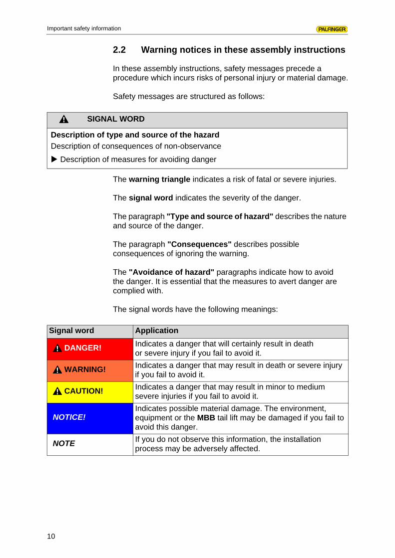
Safety messages are structured as follows:
The warning triangle indicates a risk of fatal or severe injuries.
The signal word indicates the severity of the danger.
The paragraph "Type and source of hazard" describes the nature and source of the danger.
The paragraph "Consequences" describes possible consequences of ignoring the warning.
The "Avoidance of hazard" paragraphs indicate how to avoid the danger. It is essential that the measures to avert danger are complied with.
The signal words have the following meanings:
SIGNAL WORD
Description of type and source of the hazard
Description of consequences of non-observance
Description of measures for avoiding danger
Signal word Application
DANGER! Indicates a danger that will certainly result in death or severe injury if you fail to avoid it.
WARNING! Indicates a danger that may result in death or severe injury if you fail to avoid it.
CAUTION! Indicates a danger that may result in minor to medium severe injuries if you fail to avoid it.
NOTICE!Indicates possible material damage. The environment, equipment or the MBB tail lift may be damaged if you fail to avoid this danger.
NOTE If you do not observe this information, the installation process may be adversely affected.

11
Important safety information
2.3 You must take these points into account during installation
2.3.1 General instructions
• Observe this installation manual and in particular all the safety instructions.
• Structural modifications may only be performed by MBB contract workshops. Your nearest contract workshop and other contact information can be found in the workshop directory.
• Only use MBB original parts during installation work.
• Observe all applicable accident prevention regulations.
• Observe the vehicle manufacturer's attachment guidelines.
• Observe the respectively applicable general installation diagram from MBB.
• Observe the respectively applicable general attachment report (attachment diagram) from MBB.
• Make sure that any welding work is only performed by certified welders. It is essential to comply with the vehicle maker's specifications as well as the applicable standards and regulations for welding work.
2.3.2 Before starting installation
• Before starting installation, read the safety instructions in the operating manual, especially the chapter "Care and maintenance".
• Observe the vehicle manufacturer's attachment guidelines.
• Place the vehicle on a level and firm surface for installation and align the vehicle so it is also level.
• If the vehicle has air suspension, deactivate this.
• Remove the battery terminals and ABS plugs before installation.

12
Important safety information
2.3.3 During installation
• When connecting the hydraulic parts, ensure that the connections are clean and that no contamination can get into the hydraulic circuit.
• Make sure that the MBB tail lift and its moving parts, the coupling, the brake system, the oil lines, the pneumatic lines and the cabling of the vehicle are not damaged.
• Do not apply any overpressure to the functions lift/lower, open/close, retract or extend before the installation is entirely completed.
2.3.4 During initial commissioning
• During initial commissioning of the MBB tail lift, check whether all safety and warning features are available and functional.
• Warning strips• Warning lights• Roll bar
• Lubricate all bearings and pins before initial commissioning.
13
Required tools and auxiliary equipment
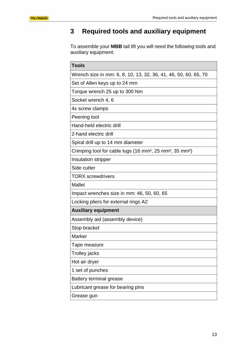
3 Required tools and auxiliary equipment
To assemble your MBB tail lift you will need the following tools and auxiliary equipment:
Tools
Wrench size in mm: 6, 8, 10, 13, 32, 36, 41, 46, 50, 60, 65, 70
Set of Allen keys up to 24 mm
Torque wrench 25 up to 300 Nm
Socket wrench 4, 6
4x screw clamps
Peening tool
Hand-held electric drill
2-hand electric drill
Spiral drill up to 14 mm diameter
Crimping tool for cable lugs (16 mm², 25 mm², 35 mm²)
Insulation stripper
Side cutter
TORX screwdrivers
Mallet
Impact wrenches size in mm: 46, 50, 60, 65
Locking pliers for external rings A2
Auxiliary equipment
Assembly aid (assembly device)
Stop bracket
Marker
Tape measure
Trolley jacks
Hot air dryer
1 set of punches
Battery terminal grease
Lubricant grease for bearing pins
Grease gun

14
List of models and scope of delivery
4 List of models and scope of delivery
Below a list of standard version models of MBB tail lifts.
The following models are available:
• 350 K to 3000 K
• 1250 KL to 2000 KL
• 1500 KL to 2000 KL
• 1500 KK to 2500 KK
• 500 KB to 750 KB
• 500 KSP to 750 KSP
• 500 K1TL/R to 1000 K1TL/R
• 500 K2TL/R to 1000 K2TL/R
• 500 KRM
• 500 du to 750 duo
• 750 Athletquattro to 1000 Athletquattro
• 750 rentfix / ML Pro to1500 rentfix / ML Pro
• 750 M
• 750 MSP
The following general drawings show the structure of the MBB tail lift and of the individual sub-assemblies.

15
List of models and scope of delivery
4.1 Standard tail lift
1 Attachment grab handle (not included in scope of delivery)
2 Side control panel (option)
3 Hydraulic unit and controller
4 Underride protection
5 Platform support rod (not included in scope of delivery)
6 Tilt switch b13, tilt switch b15
7 Tilt switch b16, tilt switch b15
8 Foot-operated switch (option)
9 Warning lamps (option)
10 Startup rail (roll bar, option)
11 Useful load centre of gravity
12 Platform
13 Torsion frame
14 Lift cylinder
15 Tilt cylinder
16 Stand tube
17 Manual cable switch (option)
12
2
3
4
5
891011
12
13
1415
16
17
67
16
List of models and scope of delivery
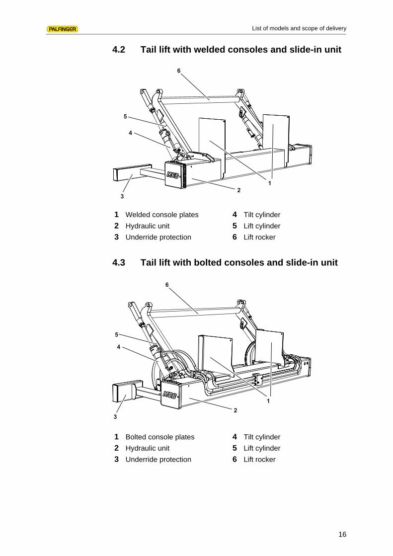
4.2 Tail lift with welded consoles and slide-in unit
4.3 Tail lift with bolted consoles and slide-in unit
1 Welded console plates
2 Hydraulic unit
3 Underride protection
4 Tilt cylinder
5 Lift cylinder
6 Lift rocker
1 Bolted console plates
2 Hydraulic unit
3 Underride protection
4 Tilt cylinder
5 Lift cylinder
6 Lift rocker
12
3
4
5
6
12
3
4
5
6

17
List of models and scope of delivery
4.4 Tail lift with platform and turning unit
4.5 Scope of delivery
The scope of delivery of your MBB tail lift is based by the model you ordered and any agreed special accessories.
1 Bolted console plates
2 Hydraulic unit
3 Underride protection
4 Tilt cylinder
5 Lift cylinder
6 Platform
7 Turning unit
123
45
6
7

18
Preparing for installation
5 Preparing for installation
This chapter contains basic information about what you need to remember when preparing to install your MBB tail lift. This information relates to the "standard" versions of all MBB tail lift models.
First read this assembly manual through and then follow the instructions step-by-step.
You should also observe the operating manual for your MBB tail lift and in particular all the safety instructions.
Perform all the preparatory work properly and carefully.
If in doubt or if you have any questions, please contact your MBB dealer before proceeding with work.
Before starting installation, please check the following points:
• Is the delivered MBB tail lift consistent with your order and have all parts required for installation been correctly delivered?
• Have the general installation diagram and the attachment report (attachment diagram) been provided in accordance with your ordered MBB tail lift type?
• Is the vehicle suitable for mounting the MBB tail lift? Do the vehicle dimensions correspond to those of the MBB tail lift?
• Is the operating voltage of the vehicle battery appropriate for the rated voltage of the MBB tail lift?
• Is the capacity of the vehicle battery sufficient for the MBB tail lift? The following capacities are required:
• Are all required tools and auxiliary equipment available? Are any another special tools required?
• Do cutouts have to be made for the lifting mechanism?
CAUTION
Incorrect installation can result in damage to the vehicle and the tail lift!
The vehicle and the tail lift may be damaged if you incorrectly install the tail lift.
It is essential to comply with the vehicle maker's guidelines for mounting attachments
It is especially important to comply with the tail lift's maximum permitted rated load and the axle spacing for the tail lift.
Load bearing capacity
12 V 24 V
500 - 1000 kg 143 Ah 105 Ah
1500 - 3000 kg 180 Ah 180 Ah

19
Preparing for installation
• Should a seal be installed in vehicles with a box body without rear doors? If yes, you must allow a space between the platform and the box body.
• Is the use of trailers planned? If yes, sufficient space for the trailer coupling must be available and the free movement of the drawbar must be ensured.
• Has allowance been made for the space required for the optional grab handle (25 mm finger room between platform and handle)?
When all these points have been checked off, you can start with the installation of your MBB tail lift. The installation consists of several steps, which are described in more detail on the following pages. They include:
• preparation of vehicle or vehicle chassis (see chapter 6 on page 20),
• installing the lifting mechanism (see chapter 7 on page 24),
• establishing electrical connections (see chapter 8 on page 37),
• installing and connecting the platform (see chapter 9 on page 42),
• adjusting and testing the platform (see chapter 10 on page 50).
20
Preparing vehicle
6 Preparing vehicle
Before mounting the MBB tail lift on your vehicle, you must prepare the vehicle accordingly. The specific steps vary according to the intended purpose and the vehicle type.
Technicalparameters
You can obtain the most important technical parameters from the general installation diagram and thus determine in advance the scope of work required to prepare the vehicle. These include:
• the installation height
• the required projection
• the position of the platform and lifting mechanism under the vehicle
• the fixing of installation aids
• the required space for the lifting mechanism for any offset rear lights
• the thickness of the vehicle's rear cross-member and any cutouts required in the lower tail chassis
To prepare the vehicle for installation of the MBB tail lift, the following steps must be completed:
• remove projecting parts of the vehicle (see chapter 6.1 onpage 21),
• make any necessary cutouts for the lifting mechanism and reinforce these (see chapter 6.2 on page 22),
• reinforce the rear cross-member, if required (see chapter 6.3on page 22).
Vehicles with boxbodies
Additional steps may be necessary for vehicles with box bodies or flat beds (with or without gates) (see chapter 6.4 on page 23). These include:
• mounting the supplied connecting profile on the vehicle,
• preparing and mounting bridging profiles/spacers,
• mounting the optional sealing system.

21
Preparing vehicle
6.1 Removing projecting parts of the vehicle
Remove all interfering components from the vehicle. These may include:
• rear lights,• reversing lights,• license plate,• spare wheel holder,• pallet carrier,• parts of the vehicle exhaust.
Store the removed components in a secure, dry place.
Components that are not compatible with your MBB tail lift may not be reinstalled.
Consult your vehicle maker to find alternative solutions for incompatible components.
ATTENTION
Damage and loss of components
If you do not safely store the removed components in a dry place, they may be damaged or lost.
Remove the interfering components carefully from the vehicle.
Store the removed components in a secure, dry place.

22
Preparing vehicle
6.2 Creating cutouts for the lifting mechanism (optional)
For most applications you will not need any special cutouts for the lifting mechanism. If this is necessary, however, you can obtain the dimensions for the cutouts from the general installation diagram or the attachment report (attachment diagram) from MBB.
Transfer the dimensions or the lifting mechanism cutouts from the attachment diagram to the vehicle chassis.
Create the cutouts according to the attachment mounting diagram and reinforce them.
Seal the blank body parts with rust protection and repaint them. Observe the vehicle manufacturer's superstructure guidelines.
6.3 Reinforcing rear cross-member (optional)
Your truck's rear cross-member must be rated for your ordered type of MBB tail lift. Your vehicle's rear cross-member should be able to bear approximately twice the rated load of your MBB tail lift (e.g. with a 1000K tail lift around 2000 kg). If the rated load of the rear cross-member is insufficient for the ordered MBB tail lift, you may have to reinforce it.

23
Preparing vehicle
6.4 Preparing vehicles with box bodies
Mountingthe sealing system
A sealing system can be ordered from MBB and pre-installed for vehicles with box bodies. The sealing system is mounted according to the special assembly instructions supplied.
Box bodies withdoors
To avoid damage to box body doors, you must attach spacers and bridging profiles. You must then abut the platform to the superstructure end with the bridging profile when the doors are open.
Prepare the spacers for the lifting mechanism area (if necessary).
Fix the spacers to the door.
Create a bridging profile (e.g. a square tube with rounded edges 60x40x3).
Mount the bridging profile over the entire loading area width.

24
Installing lifting mechanism
7 Installing lifting mechanism
There are two options for mounting the lifting mechanism:
• Installation with installation aids (see chapter 7.1 on page 24)
• Installation with mounted platform (see chapter 7.2 on page 33),
7.1 Installation with installation aids
To assist in the installation of the lifting mechanism of your MBB tail lift, you can on request obtain special installation aids. This installation aids support you in mounting the lifting mechanism. The following steps are required when installing with installation aids:
• position and fix the installation aids on the vehicle chassis (see chapter 7.1.1 on page 24)
• position lifting mechanism under the vehicle (see chapter 7.1.2 on page 25),
• bolt lifting mechanism to installation aids (see chapter 7.1.3 on page 26),
• position the stand tube (see chapter 7.1.4 on page 27),
• fix lifting mechanism with console plates to vehicle chassis (see chapter 7.1.5 on page 27),
• mount hydraulic unit (see chapter 7.1.6 on page 32),
• remove installation aids (see chapter 7.1.7 on page 32).
7.1.1 Positioning and fixing the installation aids on the vehicle chassis
CAUTION
Risk of falling equipment!
If you incorrectly position the installation aids or do not fix it correctly, the lifting mechanism may fall and cause personal injury or material damage.
Make sure that the installation aids are correctly positioned and properly fixed.

25
Installing lifting mechanism
Lay the installation aids on the loading area.
Align the installation aids on the loading area. Refer to the dimensions in the general installation diagram.
Securely fix the installation aids to the vehicle chassis with, for example, screw clamps.
7.1.2 Positioning lifting mechanism under the vehicle
Raise the lifting mechanism with suitable lifting equipment such as a forklift truck or trolley jacks, for example.
Carefully position the lifting mechanism under the vehicle.
Detach the cables and hoses and feed them through the openings provided in the vehicle chassis.
Carefully raise the lifting mechanism and move it into the installation position.
Maintain the installation position with the lifting equipment until the lifting mechanism is finally fixed to the vehicle chassis.
26
Installing lifting mechanism
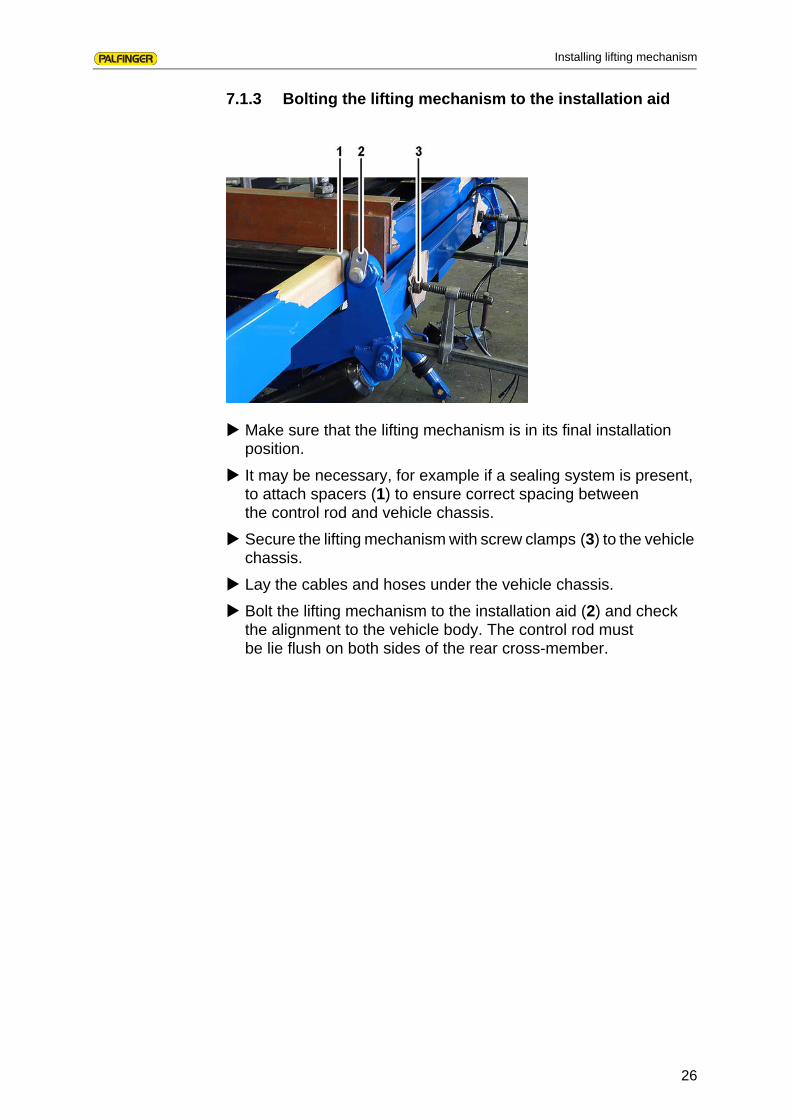
7.1.3 Bolting the lifting mechanism to the installation aid
Make sure that the lifting mechanism is in its final installation position.
It may be necessary, for example if a sealing system is present, to attach spacers (1) to ensure correct spacing between the control rod and vehicle chassis.
Secure the lifting mechanism with screw clamps (3) to the vehicle chassis.
Lay the cables and hoses under the vehicle chassis.
Bolt the lifting mechanism to the installation aid (2) and check the alignment to the vehicle body. The control rod must be lie flush on both sides of the rear cross-member.

27
Installing lifting mechanism
7.1.4 Positioning the stand tube
Adjust the stand tube height according to the general installation diagram. Ensure the greatest possible ground clearance and the free movement of all components.
Move the stand tube into the horizontal position so that the top edge is parallel to the vehicle body.
Secure the stand tube with screw clamps.
7.1.5 Fixing the lifting mechanism to console plates on the vehicle chassis
Attachment of the lifting mechanism to the vehicle chassis depends on the type of console plates used. The following console pates can be ordered from MBB:
• welded consoles
• bolted consoles
The installation sequence differs according to the type of console plates used.
The welded consoles are attached in advance by MBB to the lifting mechanism. The customer notifies MBB of the required distances between the consoles and these cannot be subsequently changed. The lifting mechanism is attached with the console plates to the vehicle chassis.
The bolted consoles are first adjusted on the lifting mechanism to the chassis size and then fixed. Together with the lifting mechanism, they are then attached to the vehicle chassis. The long holes in the bolted consoles make transverse adjustments possible.
28
Installing lifting mechanism
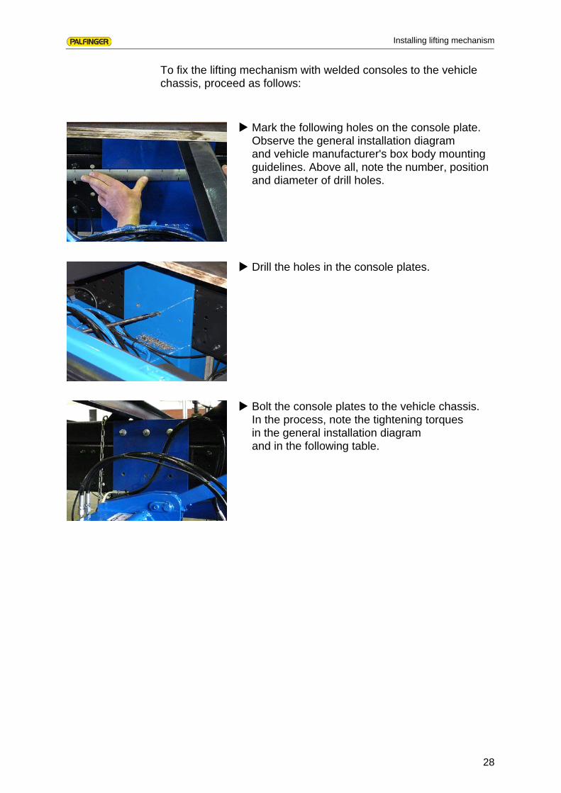
To fix the lifting mechanism with welded consoles to the vehicle chassis, proceed as follows:
Mark the following holes on the console plate. Observe the general installation diagram and vehicle manufacturer's box body mounting guidelines. Above all, note the number, position and diameter of drill holes.
Drill the holes in the console plates.
Bolt the console plates to the vehicle chassis. In the process, note the tightening torques in the general installation diagram and in the following table.

29
Installing lifting mechanism
Table 1: Tightening torques on the consoles
Type HLB Bolts/consoles Bolt typeTightening torque
350-750 K 4 M14x1.5 190 Nm
1000 KL
500-750 KB
500-750 KSP
500-750 K1TL/R
500-750 K2TL/R
500 KRM
500-1000 DUO
750 Athlet
750-1000 rentfix/ML Pro
750 M
750 MSP
1000 K 6 M14x1.5 190 Nm
1500 KL
1000 K1TL/R
1000 K2TL/R
1000 Athlet
1500 rentfix/ML Pro
1500-2000 K 10 M14x1.5 190 Nm
2000-2500 KL
2000 KK
2500 KK 1210
M14x1.5M16x1.5
190 Nm310 Nm
3000 K 14 M14x1.5 190 Nm

30
Installing lifting mechanism
To fix the lifting mechanism with bolted consoles to the vehicle chassis, proceed as follows:
Optional: Connect the locking clamps (7) to the console plate (2).
Thread the console plates (2) with the bolts (3) and the hook (4) into the mountings on the stand tube (1).
Turn the hex. nuts (5) on the bolts (3) and thus fix the console plate (2) and the U-section (6).
Align the two console plates corresponding to the frame width and pretighten the hex. nuts.
NOTE
We recommend installation of the bolted consoles to the vehicle chassis before positioning of the lifting mechanism under the vehicle.
optional
8
6
2
4
5
3
1
7
1 Stand tube
2 Console plate
3 Bolts
4 Hooks
5 Hex. nuts
6 U-section
7 Locking clamps (option)
8 Ground cable (option)

31
Installing lifting mechanism
Mount the lifting mechanism as described in section „Installing lifting mechanism“ from page 24.
Then precisely align the console plates (2) with respect to height and width to the chassis.
Fix the console plates to the vehicle chassis and tighten the hex. nuts (5).
Optional: Screw the locking clamps (7) by means of the hex. screw and nut to the stand tube (1).
Note the following tightening torques.
The bolts must be regularly retightened regularly:
• after 3 weeks in operation
• after 3 months in operation
• check and if necessary retighten half-yearly
If the battery cable is not directly connected to the battery and the ground runs over the vehicle chassis, it may be necessary to fabricate a ground cable from the delivered cable lugs and protective caps.
Cut off the required length of cable from the supplied battery cable.
Keep the ground cable (8) as short as possible and attach it to the ground screw provided on the stand tube.
Before lifting the platform, make sure that the solenoid valves on the lift cylinder can move freely at the U-section (6) of the bolted console. Otherwise you must turn the coil on the solenoid valve through 90°.
Bolts Tightening torque
Bolt M20x1.5 - St10.9 400 Nm
Bolt M14x1.5 - St10.9 190 Nm
Bolt M10 - St8.8 50 Nm
NOTE
Before connecting the ground cable, find out from the vehicle maker whether this is possible.

32
Installing lifting mechanism
7.1.6 Installing the hydraulic unit (option)
The installation of your hydraulic unit depends on the selected type. Three types are available:
• slide-in unit
• turning unit
• box unit
The hydraulic unit is normally premounted by MBB. If request, you can also obtain a box unit with long cables and hoses. You can then mount this box unit at any position at any position under the vehicle. If the cables and hoses are too long, you must bundle them and fix them under the vehicle.
7.1.7 Removing the installation aid
Remove the pins between the control rods and the installation aids and carefully fold the control rods down.
Release the screw clamps with which the installation aids are fixed to the vehicle chassis.
Remove the installation aids from the vehicle chassis.
ATTENTION
Risk of damage to components!
As there is still too little oil in the lift cylinders, the control rods can swing out in an uncontrolled fashion, thus damaging the lifting mechanism.
Carefully fold down the control rods.
33
Installing lifting mechanism
7.2 Installation with attached platform
The following steps are required when installing with premounted platform:
• position lifting mechanism under the vehicle (see chapter 7.2.1 on page 33),
• mount the platform on the lifting mechanism (see chapter 7.2.2 on page 34),
• mount auxiliary device (see chapter 7.2.3 to page 34),
• position and fix platform (see chapter7.2.4 on page 35),
• install lifting mechanism (see chapter 7.2.5 on page 36),
• remove auxiliary device (see chapter 7.2.6 on page 36).
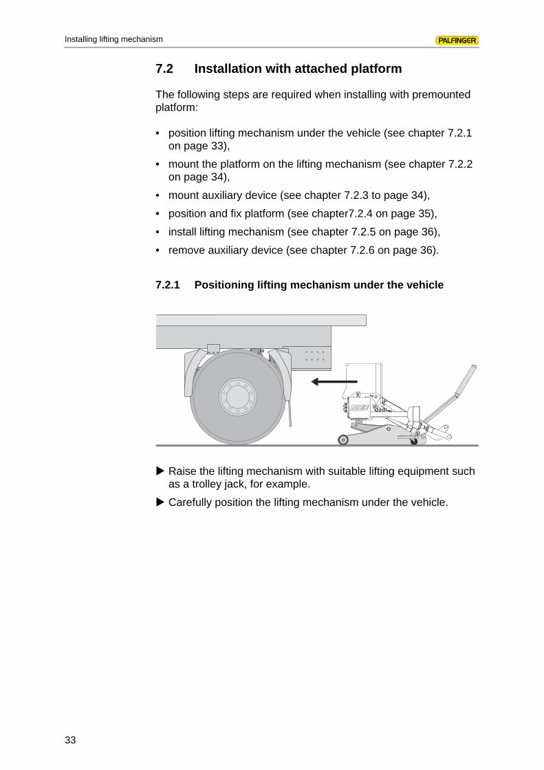
7.2.1 Positioning lifting mechanism under the vehicle
Raise the lifting mechanism with suitable lifting equipment such as a trolley jack, for example.
Carefully position the lifting mechanism under the vehicle.
34
Installing lifting mechanism
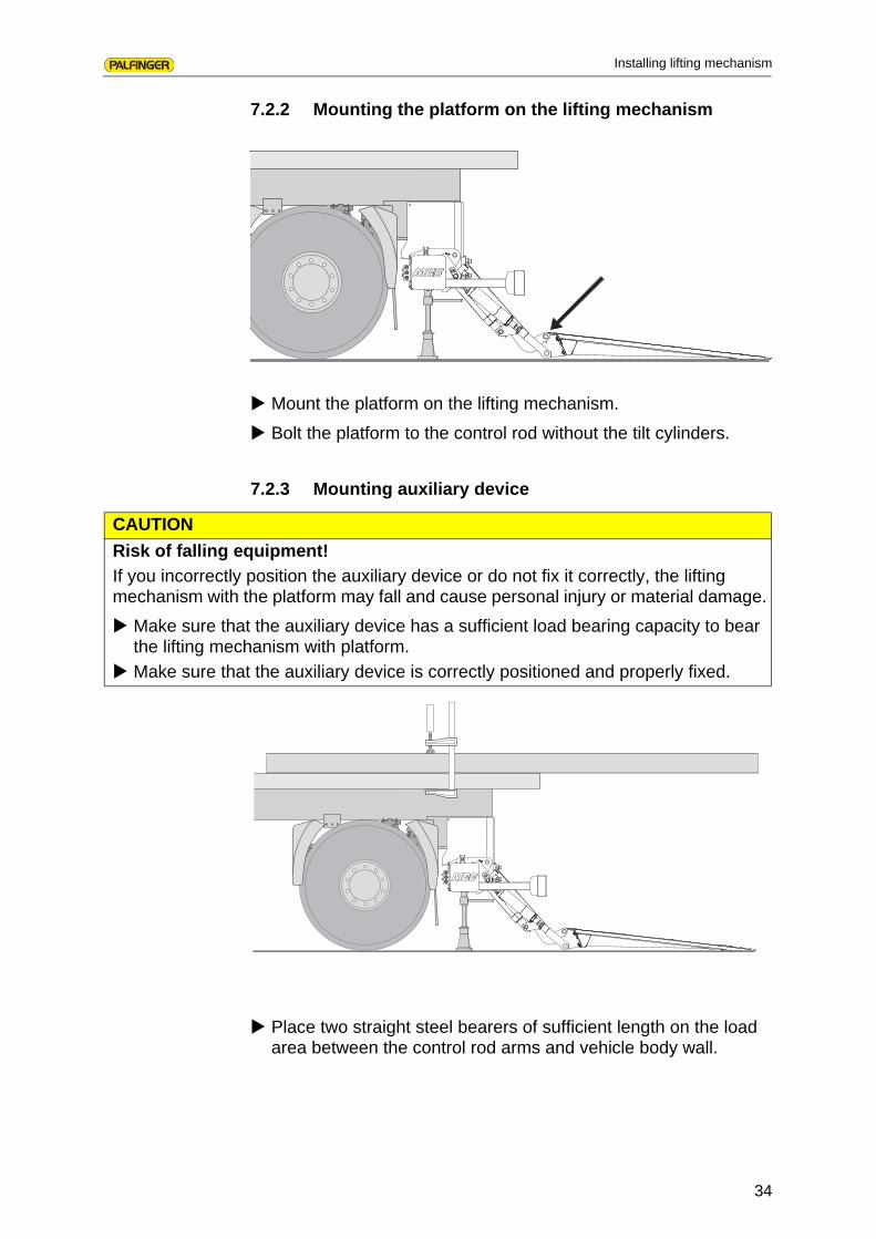
7.2.2 Mounting the platform on the lifting mechanism
Mount the platform on the lifting mechanism.
Bolt the platform to the control rod without the tilt cylinders.
7.2.3 Mounting auxiliary device
Place two straight steel bearers of sufficient length on the load area between the control rod arms and vehicle body wall.
CAUTION
Risk of falling equipment!
If you incorrectly position the auxiliary device or do not fix it correctly, the lifting mechanism with the platform may fall and cause personal injury or material damage.
Make sure that the auxiliary device has a sufficient load bearing capacity to bear the lifting mechanism with platform.
Make sure that the auxiliary device is correctly positioned and properly fixed.

35
Installing lifting mechanism
Align the auxiliary device to the load area and fix it securely to the vehicle chassis with, for example, screw clamps.
Ensure that the auxiliary device at least correspondingly projects above the platform height at the back.
7.2.4 Positioning and fixing the platform
Carefully raise the platform under the auxiliary device and align it with the body.
Make sure that the control rod heads rest up against the rear wall apron. Observe the relevant installation diagram.
Fix the platform securely to the auxiliary device. For this purpose, use appropriately rated screw clamps and additionally secure the platform against falling with trestles, for example.
Detach the cables and hoses and feed them through the openings provided in the vehicle chassis.
Carefully raise the lifting mechanism and move it into the installation position.
Maintain the installation position with the lifting equipment until the lifting mechanism is finally fixed to the vehicle chassis.

36
Installing lifting mechanism
7.2.5 Installing lifting mechanism
Proceed with the installation of the lifting mechanism from step „Positioning the stand tube“ on page 27.
Fix the lifting mechanism according to the type of console plates used (see chapter 7.1.5 on page 27).
For this purpose, use the adjustment gauge indicated on the installation diagram.
Bolt the tilt cylinders to the platform(see chapter 9.3 on page 44).
7.2.6 Removing auxiliary device
Release the screw clamps fixing the auxiliary device to the vehicle chassis.
Remove the auxiliary device from the vehicle chassis.
37
Establishing electrical connections
8 Establishing electrical connections
To electrically connect your tail lift, use the supplied MBB electrical circuit diagram and the vehicle maker's attachment guidelines. You will find the respective MBB electrical circuit diagram in the electrical unit on the circuit board.
The following steps are required:
• establish connection to vehicle battery (see chapter 8.1 on page 37),
• install and connect optional control unit (see chapter 8.2 on page 39),
• mount control panel holder (see chapter 8.3 on page 39),
• connect optional hand cable switch (see chapter 8.4 on page 40),
• connect optional remote control (see chapter 8.4 on page 40).
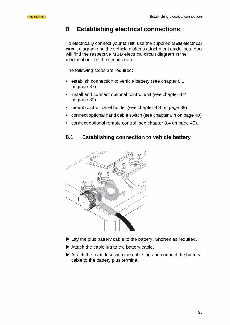
8.1 Establishing connection to vehicle battery
Lay the plus battery cable to the battery. Shorten as required.
Attach the cable lug to the battery cable.
Attach the main fuse with the cable lug and connect the battery cable to the battery plus terminal.

38
Establishing electrical connections
Optional:
Run the ground cable to the battery. Shorten as required.
Crimp the cable lug and mount it on the battery's minus terminal.
With vehicles with preinstalled VEHH interface
Plug the plus and minus cables into the mating plugs.
NOTE
With hazardous goods vehicles, the ground cable must be connected to the battery or in accordance with the respective vehicle manufacturer's guidelines for mounting attachments.

39
Establishing electrical connections
8.2 Installing and connecting the control unit
The optional control unit must be mounted in a suitable location in the driver's cab. If a control unit is already present in the vehicle, you must connect your MBB tail lift according to a special circuit diagram, which you can obtain from MBB.
Run the cable for the control unit to the driver's cab.
Select a suitable location on the dashboard in the driver's cab.
Establish an electrical connection as per the MBB circuit diagram.
Mount the control unit on the dashboard.
8.3 Mounting the control panel holder
Fix the control panel holder with screws or weld it in position as per the MBB installation diagram.
optional:connection for starting blockmax. 0.25 A
4 2 1yegn (−) 1
yegn (−)
bs3

40
Establishing electrical connections
8.4 Connecting the manual cable switch/remote control (optional)
A manual cable switch or a remote control are optionally available with your MBB tail lift.
Select a suitable place for mounting the socket under the vehicle loading bay. A fixing option is provided on most control panel holders.
Mount the socket.
Connect the cable from the manual cable switch in the terminal box in accordance with the MBB wiring diagram.
Find a suitable and secure storage location for the manual cable switch. Operation of the manual cable switch only permissible from the marked position on the platform.
NOTE
When installing a manual cable switch, you must attach the cable with socket under the vehicle loading area so that the cable can be connected to the manual cable switch.
Lead Pin Leads manual cable switch
with 3 buttons with 2 buttons
1 4 white -
2 5 green -
3 6 brown yellow
4 3 yellow red
ye/gn 2 red green/blackTable: 2 Socket connection
plugleads
holder

41
Establishing electrical connections
Wireless remotecontrol
The receiver for a wireless remote control is prewired and only has to be clipped onto to slot J31 on the circuit board and connected to ground. You will then have to attach the receiver to the stand tube. The receiver and the wireless remote control are preadjusted so that they are immediately operational. A detailed description is supplied with the wireless remote control.
NOTE
If the manual cable switch is on the attachment, this is not supplied with a socket but is connected via a junction box with the wire from the circuit board. The manual cable switch is then fixed and cannot be unplugged. The required circuit diagram is available on request from MBB.

42
Installing and connecting the platform
9 Installing and connecting the platform
If you have installed your MBB tail lift with premounted platform (see chapter 7.2 onpage 33), you can skip the first three steps in platform installation and begin with step „Adjusting the tilt cylinder“ on page 47.
The following steps are required:
• bring up the platform with the lifting equipment and position it (see chapter 9.1 on page 42)
• bolt the platform to the control rod (see chapter 9.2 on page 43),
• bolt the platform to the first tilt cylinder(see chapter 9.3 on page 44),
• adjust the tilt cylinder (see chapter 9.4 on page 47),
• bolt the platform to the second tilt cylinder (see chapter 9.5 on page 48)
• connect plug for foot-operated switch and Warnfix(see chapter 9.6 on page 48),
• install tilt sensor (see chapter 9.7 on page 49).
9.1 Moving up and positioning platform
This step is only required if you have installed your MBB tail lift with the supplied installation aids (see chapter 7.1 on page 24).
Raise the platform with a suitable lifting equipment, e.g. a forklift truck and bring the platform up to the truck tailgate.

43
Installing and connecting the platform
Carefully raise the platform and move it into the installation position at the truck tailgate.
Maintain the installation position with the lifting equipment until the platform is bolted to control rod and tilt cylinders.
9.2 Bolting the platform to the control rod
Make sure that the platform is in its final installation position.
Grease the two bearing pins.
Bolt the platform to the control rod
44
Installing and connecting the platform
9.3 Bolting the platform to the first tilt cylinder
Depending on your tail lift model, you will need to bolt one or two tilt cylinders to the platform. If your tail lift is equipped with two tilt cylinders, you should initially only bolt one tilt cylinder to the platform.
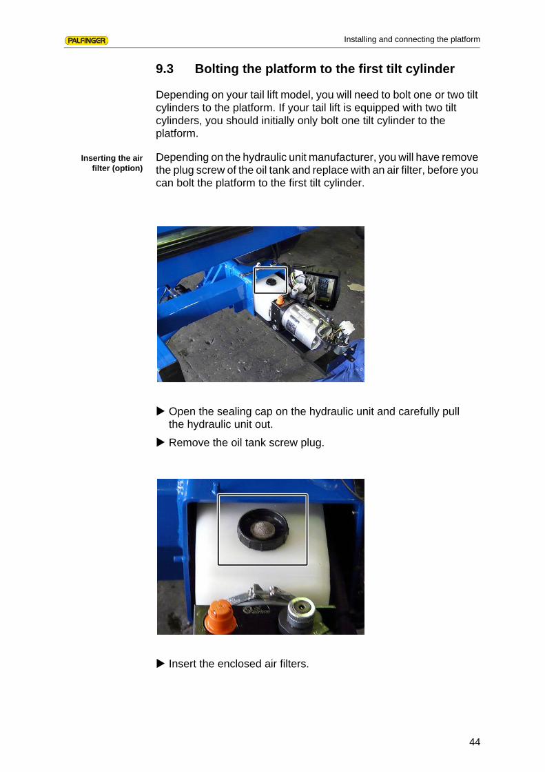
Inserting the airfilter (option)
Depending on the hydraulic unit manufacturer, you will have remove the plug screw of the oil tank and replace with an air filter, before you can bolt the platform to the first tilt cylinder.
Open the sealing cap on the hydraulic unit and carefully pull the hydraulic unit out.
Remove the oil tank screw plug.
Insert the enclosed air filters.

45
Installing and connecting the platform
Slide the hydraulic unit back in, close the sealing cap and secure this with the clip.
Then check whether the hydraulic unit is correctly connected. Refer to the enclosed hydraulic circuit plan.
Bolting the platformto the tilt cylinder
Detach the bellows hose clamp and slide the bellows down.
Turn the rod end of the tilt cylinder on the piston rod as far as it will go.
Adjust the tilt cylinder length so that it possible to easily bolt the tilt cylinder to the platform.
NOTE
To do this actuate the rotary switch for "Open" or "Close", at the same time holding the tilt sensor b15 or b16 with the cable pointing downwards (not necessary with "Basic" controller).
46
Installing and connecting the platform
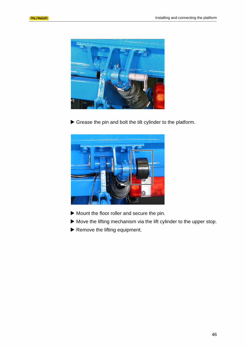
Grease the pin and bolt the tilt cylinder to the platform.
Mount the floor roller and secure the pin.
Move the lifting mechanism via the lift cylinder to the upper stop.
Remove the lifting equipment.

47
Installing and connecting the platform
9.4 Adjusting the tilt cylinder
Close the platform to the extent possible. The tilt cylinder is extended to the stop.
Release the tilt cylinder via the "Open" rotary switch.
Move the platform to the desired end position. To do this, turn the piston rod with a wrench.
Repeat the adjustment process if required, until the platform has reached the desired position.
Release the tilt cylinder by opening the platform.
Tighten the locking nut on the piston rod as per the MBB installation diagram.
Pull the bellows back over the piston rod and secure it with the clip.
NOTE
At the desired end position of the platform, the tilt cylinder must be extended to the stop.

48
Installing and connecting the platform
9.5 Bolting the platform to the second tilt cylinder (apart from the types DUO and 1000 E)
If you have bolted the platform to the first tilt cylinder, you can now bolt it to the second tilt cylinder. The second tilt cylinder is installed as described in chapter 9.3 on page 44.
9.6 Connecting plug for foot-operated switch and Warnfix
Detach the strain relief.
Pull the cables for the foot-operated switch and the Warnfix from the platform.
Connect the plugs with the plugs that come from the control rod. Make sure that colour-coding of the plugs match.
Stow the connected cables again in the tailgate.
Reconnect the strain relief.
Make sure that the attached cables are carefully laid and securely fastened. Make sure that bending lengths are sufficient.

49
Installing and connecting the platform
9.7 Installing tilt sensors
Mount the tilt sensors as shown on the right of the platform.
Feed the cables through the openings. Bundle up cables that are too long and secure these with cable binders.
Connect the cables and pull them back to the right length.
Fix the sensor to the platform.
Lay a loop for strain release.
Secure the cables with cable binders.

50
Adjusting and testing installed tail lift
10 Adjusting and testing installed tail lift
When you have installed your MBB tail lift, you must then adjust it and test that it is functioning properly. This entails the following jobs:
• opening/closing platform and setting tilt switch b13 (see chapter 10.1 onpage 50),
• air bleeding hydraulic cylinders (see chapter 10.2 onpage 51),
• checking horizontal position on ground (see chapter 10.3 on page 51),
• performing oil level check (see chapter 10.4 onpage 52),
• checking all screw connections (see chapter 10.5 on page 52),
• attaching warning strips, safety point decals (optional) and type plate (see chapter 10.6 on page 53),
• performing acceptance test as per test book(see chapter 10.7 on page 54).
10.1 Opening/closing platform and setting tilt switch b13
Close the platform via the control panel
Open the platform until it is approx. 250 mm above the ground.
Release the screw on tilt switch b13 on the right torsion arm.
Adjust tilt switch b13 so that it is horizontal.
Retighten the screw on tilt switch b13.
Fold back the safety plate.
NOTE
When the tilt sensor b15 is present on the lift arm of your tail lift, this adjustment is not required.
appr
ox. 2
50Switch b13Safety platehorizontal

51
Adjusting and testing installed tail lift
10.2 Air bleeding the hydraulic cylinders
Raise and lower the platform several times.
Open and close the platform several times.
10.3 Checking horizontal position on ground
Open and lower the platform until it sets down on the ground.
Check that the platform rests horizontally on the ground.
If the platform does not lie level, release the screw on tilt switch b16.
Adjust tilt switch b16 so that the platform rests level on the ground.
Retighten the screw on tilt switch b16.
NOTE
This test only has to be performed if tilt switch b16 is provided.
52
Adjusting and testing installed tail lift
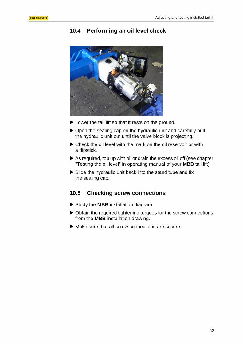
10.4 Performing an oil level check
Lower the tail lift so that it rests on the ground.
Open the sealing cap on the hydraulic unit and carefully pull the hydraulic unit out until the valve block is projecting.
Check the oil level with the mark on the oil reservoir or with a dipstick.
As required, top up with oil or drain the excess oil off (see chapter "Testing the oil level" in operating manual of your MBB tail lift).
Slide the hydraulic unit back into the stand tube and fix the sealing cap.
10.5 Checking screw connections
Study the MBB installation diagram.
Obtain the required tightening torques for the screw connections from the MBB installation drawing.
Make sure that all screw connections are secure.

53
Adjusting and testing installed tail lift
10.6 Attaching warning strips, safety point decals (optional) and type plate
The scope of delivery of all MBB tail lifts includes two warning strips. The warning strips are mounted according to the enclosed "Installation instructions for warning strips" (drawing no. 92-597.99-00.00-00).The safety point decals are only included in your scope of delivery if your tail lift is equipped with wireless remote control. In this case you will receive an installation diagram for the safety point decals (drawing no. 08-522.99-04.00-01).
Mount the warning strips according to the enclosed assembly instructions on the MBB tail lift.
If available, mount the safety point decals according to the supplied assembly instructions on the MBB tail lift.
Clean and degrease the surface for the type plate at the bottom right of the platform.
Glue the supplied type plate to the platform.
Glue the test plaque on a prominent place.

54
Adjusting and testing installed tail lift
10.7 Performing acceptance test as per test book
Perform initial commissioning in accordance with the test book.
Enter the required details in the test book.
• Company
• Code
• Installation company
• Details of signatory
It is essential that you enter the details on the operator and vehicle on page 3 as well as the form "Confirmation by the installation firm" on page 11 of the test book.
55
Index
11 Index
AAbbreviations 7Adjusting
tail lift 50tilt cylinder 47
auxiliary equipment 13
BBolting
platform to the control rod 43platform to the tilt cylinder 44platform to the tilt cylinders 44
EEnclosed documents 7
FFoot-operated switch
connecting plug 48
HHydraulic circuit diagrams 57
IInstalling
control unit 39tilt sensors 49
Installing lifting mechanismwith installation aids 24with platform 33
MModel line 14
PPersonnel qualifications 9Preparing
for installation 18vehicle 20
SSafety instructions
before starting installation 11during installation 12general 11initial commissioning 12
scope of delivery 14Set tilt switch b13
50

56
Index
TTail lift
platform 17standard 15with bolted consoles 16with welded consoles 16
Tools 13Truck
with box body 20
WWarnings
layout 10

57
Hydraulic circuit diagrams
12 Hydraulic circuit diagrams
12.1 Standard tail lift with four cylinders96-560.98-00.00-00
R2R1
DBV1
M
R5
P T
BAS5
A BAAAB
R4R3
S4S2S1S3
) ) ) ) ) ) ) )
) )
TILT
CYLINDER
LIFT
CYLINDER
TILT
CYLINDER
LIFT
CYLINDER

58
Hydraulic circuit diagrams
12.2 Standard tail lift with two cylinders97-510.98-00.00-00
R2
DBV1
M
R5
P T
BAS5
AAB
R3
S2S3
) ) ) )
) )
TILT
CYLINDER
LIFT
CYLINDER

59
Hydraulic circuit diagrams
12.3 Standard tail lift with hydraulic support96-524.98-01.00-00
B
A
S9
B V A V
S8S7
B K
A K
A H A H
A K
B K
BA
DBV1M
R5
P T
BAS5
<
AB A
R1R3
S1S3
A BA
R2 R4
S2 S4
) ) ) ) ) ) ) )
) )
TILT
CYLINDER
LIFT
CYLINDER
TILT
CYLINDER
LIFT
CYLINDER

60
Hydraulic circuit diagrams
12.4 Standard tail lift with hydraulic under-ride protection99-514.98-01.00-00/3


62
MBB PALFINGER GmbH
Fockestraße 53D-27777 Ganderkesee/Hoykenkamp
Tel.: +49-4221 8530Fax: +49-4221 87536
infombb@palfi nger.comwww.palfi nger.com/mbbcom
MBB INTER S.A.S.
Rue de l‘EgliseF-61310 Silly en Gouff ernTel.: +33-2 33 12 44 00Fax: +33-2 33 12 44 01
francembb@palfi nger.comwww.palfi nger.com
MBB PALFINGER s.r.o.
Gogolova 18SK-85101 Bratislava
Tel.: +421-252 636 611Fax: +421-252 636 612mbbhubfi [email protected]
RATCLIFF PALFINGER Ltd.
Bessemer RoadWelwyn Garden CityUK-Herts AL7 1ET
Tel.: +44-01707 325571Fax: +44-01707 327752
inforatcliff @palfi nger.comwww.palfi nger.com