assembly instructions - jack docks
TRANSCRIPT

ASSEMBLY INSTRUCTIONS Congratulations on your new Patriot Dock purchase. This manual contains instructions to assemble basic dock config-urations for use at typical residential shoreline application. Please read through entire instructions before starting. Please visit www.patriotdocks.com for step-by-step video instructions and more information.
General Guidelines: Wear protective gloves and appropriate safety glasses when assembling the Patriot Dock. The maximum unsupported span for Patriot Aluminum Dock Frames is 16 feet, in the water or while in
storage. The dock is designed to carry a maximum of 500 pounds over any 4 ft x 4 ft part of the deck and a maxi-mum of 1000 pounds between supports spaced 16 feet apart. Always support outside corners and use additional supports in high traffic areas or where greater loads are expected. Please see the recommended support loca-tions depicted below.
Never push or pull the aluminum dock with a winch, ATV or vehicle. Always remove decking panels and raise pipes not supported by wheels when pulling the frame in or out of the
water. Docks are not to be left in freezing water. All dock surfaces can be slippery when wet. Please use caution when stepping or walking on any dock surface. The dock should have no unsupported span greater than 16 feet while in use or while in storage. Never leave the lake end of the dock unsupported. Always support corners of the Patio platform. Roll-in kits should be installed at the very end of the dock for best stability. Additional posts may be required if roll-
in kits are installed at locations other than what is recommended. Always assemble the dock frame so there is a 4 ft. Truss End Rail (PN 10803) every 4 feet and at both ends of
the dock. Patio sections must be closed on both ends using the 4 ft. Truss End Rail. Install flat Transition Plates when connecting two 8 ft. frame assemblies (bottom only). Transition Plates are not
required at joints with support legs. Patriot docks are modular allowing for the flexibility to add length or change the configuration as desired. Addition-
al parts may be required for certain configurations. Tools Required: 1/2” , 9/16” and 3/4” Wrenches or ratchet w/ sockets, mallet Recommended Tools: Cordless Impact wrench / drill with above socket sizes, work gloves, safety glasses
www.patriotdocks.com

Standard Pipe Lengths: < 16’ = 4’ pipe 17’- 32’ = 6’ pipe 33’+ = 8’ pipe
PN10800 Aluminum Frame 4’x8’
1. (2) 4’ Truss End Rail
2. (1) Left Side Rail
3. (1) Right Side Rail
4. (1) Connecting Rail
5. (1) Short SHORE END Center Support Tube (47”)
6. (1) Long LAKE END Center Support Tube (48”)
7. (1) 8’ Diagonal Brace (8’x 1”x 1” angle) (not shown)
8. (1) Transition plate (17.5”x 1.5” flat bar) (not shown)
Parts List Assembly Hardware
A. (20) 3/8”-16 x 1.25” Bolt
B. (2) 3/8”-16 x 1.5” Bolt
C. (22) 3/8”-16 Nut
Lake End
Shore End
www.patriotdocks.com
Support Locations

Patriot Dock Assembly
Helpful Hints for Patriot Dock Assembly: 1. Visit www.patriotdocks.com for step-by-step photo and video instructions under the Instructions and FAQ sections.
2. Each frame section is NOT built individually. Each additional section is attached and built off of the previous section.
3. Do not tighten any bolts until the frame or frames are fully assembled.
4. The 4 ft. Truss End Rail and Connecting Rail (Items 3 and 4) always fit inside the vertical angles of the 8’ Side Rails.
5. Use the shorter 3/8” –16 X 1.25” bolts (Item A) for all joints except the center of the Connecting Rail (Item 4), where
the two 3/8” –16 X 1.50” bolts are used (Item B).
Frame Assembly Steps (diagrams on page 4 and 5):
• Layout all the 4 x 8 ft frame components on level ground. Orient the components so the Short Center Support Tube
(Item 5) is on the shore end of the frame and the Long Center Support Tube (Item 6) is on the lake end of the frame. See
drawings for reference.
• Starting with the shore end of the frame, loosely bolt the 4 ft Truss End Rail (Item 1) to the Left and Right Side Rails
(Item 2 and 3) using the 3/8”x1.25” bolt and nut. Note: The lip on the side rails face upward. Notice the orientation
of the center vertical angle on the Side Rails, this determines Left and Right sides. • Bolt the second 4 ft Truss End Rail (Item 1) at the center of the two Side Rails.
• Bolt the Short Center Support Tube between the two End Rails on the shore end of the frame. Do not install the 3/8”
nuts until after the next step. • Bolt the Long Center Support Tube between the middle 4’ Truss End Rail (Item 1) and Connecting Rail (Item 4) using
the 3/8” x 1.25” long bolts. Wait to install 3/8” nuts until after next frame section has been joined to the first.
• Connect the next 4 x 8 ft frame by fitting the two Side Rails and 4 ft Truss End Rail into the bolts from the previous
step and install the 3/8” nuts to fasten the joint. See drawings on next page.
• Finish attaching the remaining 4 x 8 ft frames by repeating steps above. Repeat until the entire straight frame is assem-
bled.
• Lastly, install the loose 4 ft Truss End Rail (Item 1) to the lake end of the straight length dock frame (shown in red on
next page). Tighten all bolted connections throughout the dock assembly.
• Rotate dock frame on its side or prop up frame on blocks to install Transition Plates (Item 8) and 8 ft Diagonal Braces
(Item 7) in the holes on the bottom of the assembled frames. The Transition Plates strengthen the connection between 4
x 8 ft connecting frames. The Diagonal Braces are installed under each 8 ft frame, alternating directions on each frame.
The braces will form a Z type pattern under the frame to control swaying.
• If your dock has a Patio or “L” configuration, preassemble the 4 x 8 frame and connect to the straight dock section us-
ing six 3/8” x 1.25” bolts and nuts.
Pipe or Jack Supports (see page 6 for illustrations):
Fasten Jack Supports or Pipe Supports to the frame, making sure there is no span greater than 16 ft. between supports.
Pipe: Pipe Holders mount to the 1/2” holes in the vertical angles of the Side Rails. Insert pipe through Pipe Holder to de-
sired height. Fasten Foot Plates to the bottom and add the pipe cap to the top. For Roll in pipe docks, install axle convertor
(L-shaped unit) to the bottom of the vertical pipes. The Axle Converter should be oriented to that the closed sleeve accepts
the vertical pipe and the through sleeve accepts the axle pipe. Orientate the “L” brackets inward. Feed horizontal axle pipe
(6’ for straight docks and 8’ for patio docks) through both Axle Converter brackets. Add wheels and secure with stop
clamps. Drill up to four 3/8” holes on one side of each wheel, at any of the 4 dimple locations, so wheel fills with water .
Screw Jacks: Screw Jacks bolt to the frame using the 3/8” holes near each vertical angle on the Side Rails. Add Drop Leg
to jack and set to desired height. For Roll in Jack Docks, simply mount the aluminum axle to the bottom of the jack (do not
use Drop Leg components when attaching the axle), add the wheel and secure in place. Jack fenders (PN10886) are installed
last using two 3/8”x3.5” bolts/nuts.
Add Decking:
• Drop in 4’ x 4’ decking panels after dock assembly is in the water and the height is adjusted. If you purchased alumi-
num dock panels, install adhesive backed rubber to the top of the side rails and the center of the frame before installing
the deck panels.
• Use the optional Deck Locker or add your own locking screws, bolts or zip ties to fasten the decking panels to the frame
using the single hole in the stringers (poly and aluminum decking) if desired.
• Remove decking before moving the dock frame out of the water for storage. Stack and cover the decking for protection
in the off season.
www.patriotdocks.com

DO NOT assemble frames individually. Join frames
together while assembling. Assembly hardware passes
through the lake end of the first frame and through the
shore end of the next frame.
The 4’ Truss End Rail on the lake face of the dock
(marked in red) is not included in the PN10800
Frame Assembly.
ABOVE: Top view of two frames being joined together.
Assembly bolts pass through all aluminum components being joined together.
See diagram on next page for further joint details, including Diagonal Brace and
Transition Plate installation.
After straight run of pier is assembled, patio sections
can be added.
Assemble patio section completely. Bolt parallel to
straight pier using six 3/8” bolts.
Lake
Shore
www.patriotdocks.com
Terminal ends of completed
pier are always to be finished
with a 4’ Truss End Rail
(shown in red).

Th
e Diag
on
al Braces an
d T
ransitio
n P
lates share th
e same m
ou
ntin
g h
oles an
d assem
bly
bo
lts.
Th
e Diag
on
al Braces sh
ou
ld altern
ate directio
n o
n each
frame, creatin
g a zig
-zag p
attern.

www.patriotdocks.com
1/2” Bolts
Install Post Bracket
using two 1/2” bolts.
(included with Post
Bracket)
Loosen set bolts,
install 1-1/2” i.d.
schedule 40 support
pipes and add Pipe
Caps and either Foot
Plate bases or the
axle components.
Install Aluminum Jack
using four 3/8” bolts.
Add Drop Leg or Axle
attachment.
Install optional fender to
the Jack using two of the
alternate mounting holes.
Support Locations
Shore end of assembled dock
rests on and is supported by
the shoreline.
Optional Shore Ramps are
available. Corners of patio sections
need supports.
Jack Supports Pipe Supports
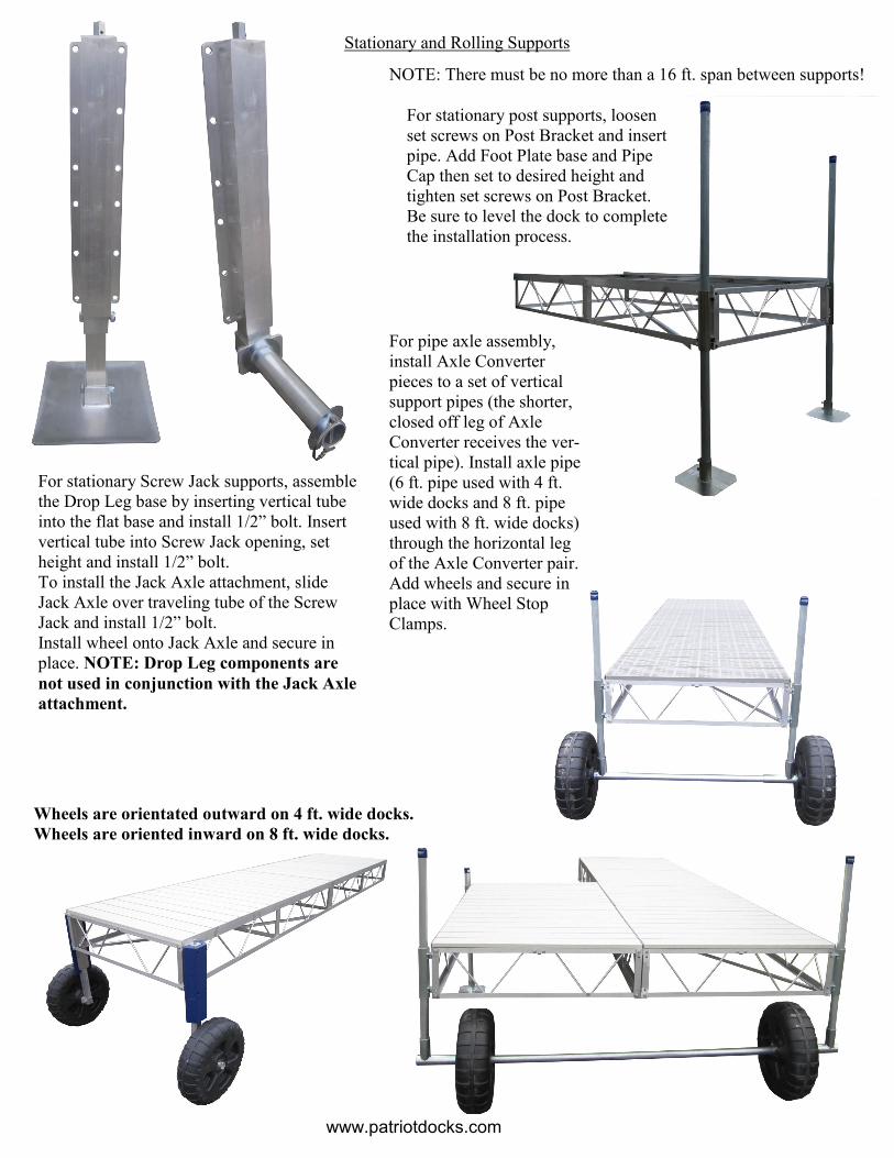
Stationary and Rolling Supports
NOTE: There must be no more than a 16 ft. span between supports!
For stationary post supports, loosen
set screws on Post Bracket and insert
pipe. Add Foot Plate base and Pipe
Cap then set to desired height and
tighten set screws on Post Bracket.
Be sure to level the dock to complete
the installation process.
For stationary Screw Jack supports, assemble
the Drop Leg base by inserting vertical tube
into the flat base and install 1/2” bolt. Insert
vertical tube into Screw Jack opening, set
height and install 1/2” bolt.
To install the Jack Axle attachment, slide
Jack Axle over traveling tube of the Screw
Jack and install 1/2” bolt.
Install wheel onto Jack Axle and secure in
place. NOTE: Drop Leg components are
not used in conjunction with the Jack Axle
attachment.
Wheels are orientated outward on 4 ft. wide docks.
Wheels are oriented inward on 8 ft. wide docks.
For pipe axle assembly,
install Axle Converter
pieces to a set of vertical
support pipes (the shorter,
closed off leg of Axle
Converter receives the ver-
tical pipe). Install axle pipe
(6 ft. pipe used with 4 ft.
wide docks and 8 ft. pipe
used with 8 ft. wide docks)
through the horizontal leg
of the Axle Converter pair.
Add wheels and secure in
place with Wheel Stop
Clamps.
www.patriotdocks.com
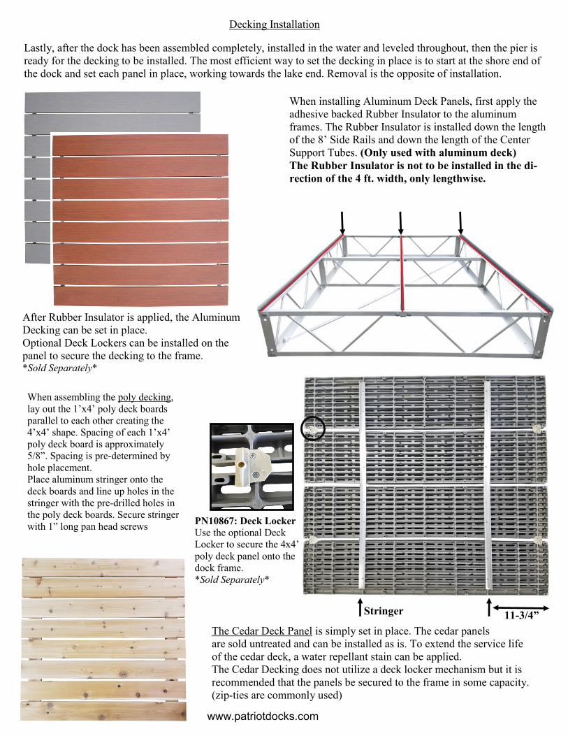
Decking Installation
Lastly, after the dock has been assembled completely, installed in the water and leveled throughout, then the pier is
ready for the decking to be installed. The most efficient way to set the decking in place is to start at the shore end of
the dock and set each panel in place, working towards the lake end. Removal is the opposite of installation.
When installing Aluminum Deck Panels, first apply the
adhesive backed Rubber Insulator to the aluminum
frames. The Rubber Insulator is installed down the length
of the 8’ Side Rails and down the length of the Center
Support Tubes. (Only used with aluminum deck)
The Rubber Insulator is not to be installed in the di-
rection of the 4 ft. width, only lengthwise.
www.patriotdocks.com
The Cedar Deck Panel is simply set in place. The cedar panels
are sold untreated and can be installed as is. To extend the service life
of the cedar deck, a water repellant stain can be applied.
The Cedar Decking does not utilize a deck locker mechanism but it is
recommended that the panels be secured to the frame in some capacity.
(zip-ties are commonly used)
When assembling the poly decking,
lay out the 1’x4’ poly deck boards
parallel to each other creating the
4’x4’ shape. Spacing of each 1’x4’
poly deck board is approximately
5/8”. Spacing is pre-determined by
hole placement. Place aluminum stringer onto the
deck boards and line up holes in the
stringer with the pre-drilled holes in
the poly deck boards. Secure stringer
with 1” long pan head screws
PN10867: Deck Locker
Use the optional Deck
Locker to secure the 4x4’
poly deck panel onto the
dock frame.
*Sold Separately*
11-3/4”
After Rubber Insulator is applied, the Aluminum
Decking can be set in place.
Optional Deck Lockers can be installed on the
panel to secure the decking to the frame. *Sold Separately*
Stringer