assembly instructions signature choral riser siderail signature … · · 2017-11-29assembly...
TRANSCRIPT

Assembly InstructionsSignature® Choral Riser
Siderail
©Wenger Corporation 2017 Printed in USA 10/17 Part #098G497-01
Wenger Corporation, 555 Park Drive, P.O. Box 448, Owatonna, Minnesota 55060-0448
Questions? Call.....USA: (800) 4WENGER (493-6437) • Worldwide: +1(507) 455-4100 • www.wengercorp.com
Contents
Visit the Signature Choral Risers web page at www.wengercorp.com for detailed instructions and videos.
Note: Please read and understand these instructions before assembling or setting up.Note: If you need additional information, contact Wenger Corporation using the information below.
Signature Choral 3-Step Riser with Optional Siderail
Signature Choral 4-Step Riser with Optional Siderail
Important User Information . . . . . . . . . . . . . . . . . . . . . . . . . . .2General . . . . . . . . . . . . . . . . . . . . . . . . . . . . . . . . . . . . . .2Manufacturer . . . . . . . . . . . . . . . . . . . . . . . . . . . . . . . . . .2Intended Use . . . . . . . . . . . . . . . . . . . . . . . . . . . . . . . . . .2Warranty . . . . . . . . . . . . . . . . . . . . . . . . . . . . . . . . . . . . .2
Parts List . . . . . . . . . . . . . . . . . . . . . . . . . . . . . . . . . . . . . . . . .3Hardware Pack - Required Tools . . . . . . . . . . . . . . . . . .3Hardware Pack - Fasteners . . . . . . . . . . . . . . . . . . . . . .3Siderail Components . . . . . . . . . . . . . . . . . . . . . . . . . . . .3
Before Assembly . . . . . . . . . . . . . . . . . . . . . . . . . . . . . . . . . . .4Determine Riser Configuration . . . . . . . . . . . . . . . . . . . . . . . .5Front Mount Installation . . . . . . . . . . . . . . . . . . . . . . . . . . . . . .6Rear Mount Installation . . . . . . . . . . . . . . . . . . . . . . . . . . . . . .10Siderail Installation . . . . . . . . . . . . . . . . . . . . . . . . . . . . . . . . .12Safety Check . . . . . . . . . . . . . . . . . . . . . . . . . . . . . . . . . . . . . .15Removing the Siderail . . . . . . . . . . . . . . . . . . . . . . . . . . . . . . .16
2
Important User InformationGeneralCopyright © 2017 by Wenger Corporation
All rights reserved. No part of the contents of this manual may be reproduced, copied, or transmitted in any form or by any means including graphic, electronic, or mechanical methods or photocopying, recording, or information storage and retrieval systems without the written permission of the publisher, unless it is for the purchaser’s personal use.
Printed and bound in the United States of America.
The information in this manual is subject to change without notice and does not represent a commitment on the part of Wenger Corporation. Wenger Corporation does not assume any responsibility for any errors that may appear in this manual.
In no event will Wenger Corporation be liable for technical or editorial omissions made herein, nor for direct, indirect, special, incidental, or consequential damages resulting from the use or defect of this manual.
The information in this document is not intended to cover all possible conditions and situations that might occur. The end user must exercise caution and common sense when assembling or installing Wenger Corporation products. If any questions or problems arise, call Wenger Corporation at 1-800-887-7145.
ManufacturerThe Signature® Choral Riser Siderail is manufactured by:
Wenger Corporation 555 Park Drive Owatonna, MN 55060 (800) 4WENGER (493-6437) • +1 (507) 455-4100 www.wengercorp.com
Intended Use· This product is designed to only be installed on Wenger Signature 3-Step and 4-Step Choral Risers.
· This product is intended for indoor use in normal ambient temperature and humidity conditions — it must not be exposed to prolonged outside weather conditions.
· This product is intended to be assembled only as described in these instructions.
WarrantyThis product is guaranteed free of defects in materials and workmanship for fifteen full years from date of shipment. A full warranty statement is available upon request.

3
Hardware Pack - Required Tools
Two 5mm Hex Wrenches
Parts List
1
7/32 Hex Wrench
2
Siderail Components
Hardware Pack - Fasteners
Reversed Upper Bracket
3
The following required tools are included in the Hardware Pack.
Depending on the individual Signature Riser configuration, all included fasteners may not be used.
3/8-16 Wing Nut
4
3/8-16 x 1-3/4” Socket Screw
5
3/8-16 Knob
6
3/8-16 x 2-1/2” Snap Pin
7
5/16-18 x 2-1/4” Threaded Rod
8
3/8-16 x 2” Carriage Bolt
9
Joint Connector Nut
10
Item Description11 Rear Mount12 Siderail Loop13 Upright Tube14 Front Mount
1112
13
14
4
ATTENTION!!!The Siderail is intended for use with the Signature Choral Risers set up in either an Arc or Straight Configuration, see these instructions for variations in the assembly. These assembly procedures are shown using a common 4-Step Standard Assembly Riser. The procedure is the same for all models and configurations unless otherwise indicted.
Pre-Assembly Notes· Siderail Assemblies are sold and shipped in pairs.
These instructions are for assembling one Siderail at a time.· The Siderail must be removed to fold up the Risers but the Front and Rear Mount Brackets
can remain on the Riser when it is stored. · Be sure to install the Siderail Assembly on the Risers that will be at the ends of a
multiple Riser configuration.
Before Assembly
5
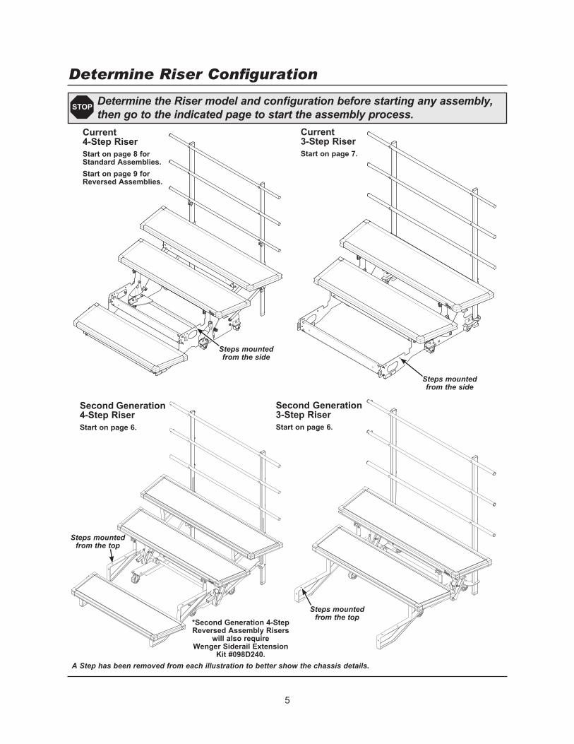
Steps mounted from the side
Determine Riser Configuration
A Step has been removed from each illustration to better show the chassis details.
Determine the Riser model and configuration before starting any assembly, then go to the indicated page to start the assembly process.
STOP
Steps mounted from the top
Second Generation 3-Step RiserStart on page 6.
Current 3-Step RiserStart on page 7.
Second Generation 4-Step RiserStart on page 6.
Current 4-Step RiserStart on page 8 for Standard Assemblies.Start on page 9 for Reversed Assemblies.
*Second Generation 4-Step Reversed Assembly Risers
will also require Wenger Siderail Extension
Kit #098D240.
Steps mounted from the side
Steps mounted from the top

6
Second Generation 3-Step Riser
(Standard or Reversed)
3/8-16 Wing Nut
(4)
1. On a 3-Step Riser, attach the Front Mount (14) below the first step at the back side of the riser frame.
On a 4-Step Riser, attach the Front Mount (14) below the second step at the back side of the riser frame. *Second Generation 4-Step Reversed Assembly Risers will also require Wenger Kit #098D240.
2. Secure the Front Mount using two 3/8” x 2” Carriage Bolts (9) and two 3/8-16 Wing Nuts (4). Install the first Carriage Bolt and Wing Nut loosely to allow Front Mount movement for the second set.
3. Tighten all Wing Nuts.4. Proceed to “Rear Mount Installation” on page 10 or 11.
Front Mount Installation — Second Generation Risers
3/8-16 x 2” Carriage Bolt
(9)
Front Mount (14) Open side
faces forward
First Step has been removed from the
illustration to better show the Front Mount location.
Second Step has been removed from the
illustration to better show the Front Mount location.
This procedure details Front Mount Assembly for Second Generation Risers only. See page 5 for clarity.
STOP
3/8-16 Wing Nut
(4)
3/8-16 x 2” Carriage Bolt
(9)
Front Mount (14) Open side
faces forward
*Second Generation 4-Step Reversed Assembly Risers will also require Wenger Siderail Extension Kit #098D240.
Second Generation 4-Step Riser
(Standard or Reversed)
7
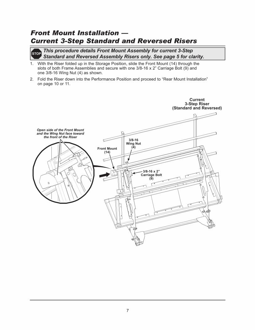
1. With the Riser folded up in the Storage Position, slide the Front Mount (14) through the slots of both Frame Assemblies and secure with one 3/8-16 x 2” Carriage Bolt (9) and one 3/8-16 Wing Nut (4) as shown.
2. Fold the Riser down into the Performance Position and proceed to “Rear Mount Installation” on page 10 or 11.
This procedure details Front Mount Assembly for current 3-Step Standard and Reversed Assembly Risers only. See page 5 for clarity.
STOP
3/8-16 x 2” Carriage Bolt
(9)
3/8-16 Wing Nut
(4)Front Mount (14)
Front Mount Installation — Current 3-Step Standard and Reversed Risers
Open side of the Front Mount and the Wing Nut face toward
the front of the Riser
Current 3-Step Riser
(Standard and Reversed)

1. With the Riser folded up in the Storage Position, slide the Front Mount (14) through the front slots of both Frame Assemblies and secure with one 3/8-16 x 2” Carriage Bolt (9) and one 3/8-16 Wing Nut (4) as shown.
For Standard Assemby Risers use the front slots.
2. Fold the Riser down into the Performance Position and proceed to “Rear Mount Installation — 3-Step and 4-Step Standard Assembly Risers” on page 10.
8
This procedure details Front Mount Assembly for Current 4-Step Standard Assembly Risers only. See page 5 for clarity.
STOP
Front Mount Installation — Current 4-Step Standard Assembly Risers
3/8-16 x 2” Carriage Bolt
(9)
3/8-16 Wing Nut
(4)
Open side of the Front Mount faces toward the
front of the Riser
Current 4-Step Riser
(Standard Assembly)
Wing Nut faces toward the front of the Riser
Front slot for Standard Assembly
Risers
Do not use rear slot
Front Mount (14)
Front Mount through
Front Slots
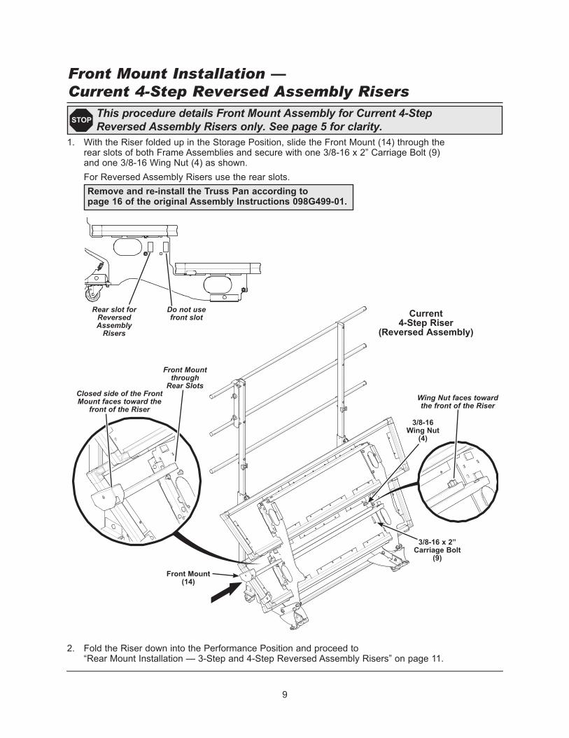
1. With the Riser folded up in the Storage Position, slide the Front Mount (14) through the rear slots of both Frame Assemblies and secure with one 3/8-16 x 2” Carriage Bolt (9) and one 3/8-16 Wing Nut (4) as shown.
For Reversed Assembly Risers use the rear slots.
2. Fold the Riser down into the Performance Position and proceed to “Rear Mount Installation — 3-Step and 4-Step Reversed Assembly Risers” on page 11.
9
This procedure details Front Mount Assembly for Current 4-Step Reversed Assembly Risers only. See page 5 for clarity.
STOP
Front Mount Installation — Current 4-Step Reversed Assembly Risers
Do not use front slot
Rear slot for Reversed Assembly
Risers
3/8-16 x 2” Carriage Bolt
(9)
3/8-16 Wing Nut
(4)
Front Mount (14)
Closed side of the Front Mount faces toward the
front of the Riser
Current 4-Step Riser
(Reversed Assembly)
Wing Nut faces toward the front of the Riser
Remove and re-install the Truss Pan according to page 16 of the original Assembly Instructions 098G499-01.
Front Mount through
Rear Slots

10
Current 3-Step Riser
(Standard and Reversed)
1. Slide the Rear Mount (11) over the ends of the top two Backrail Horizontal Tubes as shown. Align the holes in the Rear Mount with the holes at the end of the Backrail Horizontal Tubes.
2. Secure the Rear Mount to the Backrail Horizontal Tubes using two 3/8-16 x 1-3/4” Socket Screws (5).
Note: These screws extend through the hole in the Backrail Horizontal Tubes and tighten against the opposite side. Tighten these screws using the 7/32” Hex Wrench (2).
Loosen the two Wing Nuts on the Rear Mount until they reach the Acorn Nut.
3. Proceed to “Siderail Assembly” on page 12.
This procedure details Rear Mount Assembly for 3-Step and 4-Step Standard Assembly Risers only. See page 5 for clarity.
STOP
Rear Mount Installation — 3-Step and 4-Step Standard Assembly Risers
Rear Mount (11)
3/8-16 x 1-3/4” Socket Screw
(5)
Loosen Wing Nuts
Rear Mount tab faces back

11
1. The Backrail Horizontal Tubes must be removed and re-attached.a. Remove the top two Tubes.b. Attach one Reversed Upper Bracket (3) behind one side of the top two Tubes
using the existing fasteners as shown.c. Reattach the opposite side of the Tubes.
2. Slide the Rear Mount (11) over the ends of the top two Backrail Horizontal Tubes. Align the holes in the Rear Mount with the holes in the Reversed Upper Bracket.
3 Secure the Rear Mount to the Reversed Upper Brackets using one 3/8-16 x 1-3/4” Socket Screw (5) in each.
Note: These screws extend only through the hole in the Reversed Upper Brackets and tighten against the outside of the Backrail Horizontal Tubes. Tighten these screws using the 7/32” Hex Wrench (2).
Loosen the two Wing Nuts on the Rear Mount until they reach the Acorn Nut.
4. Proceed to “Siderail Assembly” on page 12.
This procedure details Rear Mount Assembly for 3-Step and 4-Step Reversed Assembly Risers only. See page 5 for clarity.
STOP
Rear Mount Installation — 3-Step and 4-Step Reversed Assembly Risers
Rear Mount (11)
3/8-16 x 1-3/4” Socket Screw
(5)Loosen Wing Nuts
Rear Mount tab faces forward
Reversed Upper Bracket
(3)
Existing fasteners
Screws will not be flush
Step 1
Steps 2 and 3

12
Siderail Assembly1. Attach the Upright Tube.
a. Insert the 3/8-16 x 2-1/2” Snap Pin (7) into the single hole at the bottom of the Upright Tube (13). Close the wire retainer over the pin to keep it in place.
b. Place the Snap Pin end of the Upright Tube into the Front Mount. The Snap Pin will prevent the Upright Tube from sliding through the Front Mount but it will still be loose.
Upright Tube (13)
Snap Pin (6)
into single hole toward bottom

13
Siderail Assembly (continued)2. Attach the Siderail Loop.
a. Place the Siderail Loop (12) onto the Rear Mount, over the Wing Nuts and slide it to the bottom of the mounting slots. Don’t tighten the Wing Nuts yet and be sure that the Siderail Loop is toward inside of the Upright Tube.
b. Thread one 5/16-18 x 2-1/4” Threaded Rod (8) into a Joint Connector Nut (10). c. Slide them both through the top hole in the Upright Tube and the Siderail Loop.
secure at the other side with an additional Joint Connector Nut (10). Use the two 5mm Hex Wrenches (1) to tighten them securely.
d. Repeat steps 2b and 2c for the bottom hole in the Upright Tube and Siderail Loop.
5/16-18 x 2-1/4” Threaded Rod
(8)
Mounting slots
Siderail Loop (12)
Joint Connector Nut
(10)
Joint Connector Nut
(10)

14
Siderail Assembly (continued)3. Attach the Knob.
a. Thread the Knob (6) into the hole of the Front Mount. Tighten securely against the Upright Tube to stabilize it.
b. Tighten the Wing Nuts on the Rear Mount against the plate on the Siderail Loop.
Knob (6)
Tighten the Wing Nuts

15
Before each use, with the Siderail attached check the components for tightness and condition:
a. Front Mount Knob and Fasteners.b. Rear Mount Wing Nuts and Fasteners.
Safety Check
Front Mount Knob and Fasteners
Rear Mount Wing Nuts and Fasteners

16
1. To remove the Siderail and Upright, loosen the Knob on the Front Mount and both Wing Nuts on the Rear Mount.
2. Lift the Upright Tube out of the Front Mount and rotate the Side Loop off of the Rear Mount.
3. The Riser can be folded and moved with the Front and Rear Mounts attached.
Removing the Siderail
Loosen Knob
Loosen Wing Nuts