assembly manual - bob parker's electronic stuff
TRANSCRIPT

PROJECT INFORMATION SUPPLIED BY
Text and illustrations courtesy of Silicon Chip
IT’S HARD TO BELIEVE that it’salready eight years since my first ESR
(equivalent series resistance) meter wasdescribed – in the January 1996 editionof “Electronics Australia”. It wasdesigned on a 386 PC!
The ESR meter allowed service techni-cians to quickly and easily identifydefective electrolytic capacitors whilethey were still in circuit. It measures acharacteristic of electrolytic capacitorswhich is very important: the “equivalentseries resistance” or ESR.
Back then, no-one (including myself)expected that a meter designed to meas-ure a capacitor characteristic hardly any-one had ever heard of would becomepopular in Australia, let alone overseas.However, we didn’t consider the explo-sive growth of the Internet. Thanks topeople discussing it on various news-groups and by email, about 12,000 ESR
meter kits have now been sold and sales(mainly outside Australia) continue to bestrong.
Over those eight years, both DickSmith Electronics (which sells the kit)and the author have received many sug-gestions from constructors on improvingthe ESR meter kit – particularly on mak-ing the construction easier. This upgrad-ed version is the result and incorporatesmany of those ideas. As before, it will beavailable as a complete kit from DSE.
What’s ESR?
Before taking a look at what’s changedin this “Mk2” version of the ESR meter,let’s take a look at what an ESR meterdoes. First, we need to get into a bit ofboring theory to understand how elec-trolytic capacitors (which I’ll refer tosimply as “electrolytics” from here on)are constructed and work. This is neces-
sary to understand why they cause somany electronic faults.
Fig.1 is a simplified cross-sectiondrawing which shows the basics. As withmany other kinds of capacitors, theplates of an electrolytic consist of twolong aluminium foil strips wound into acylinder. The big difference is that the
Assembly Manual
KK II TT
ESR Meter Mk.2 K 7214
Please read Disclaimer carefully as wecan only guarantee parts and not thelabour content you provide.
Cat No.
Forget about capacitance meters - an ESR meter is the way to go when it comes to identifyingfaulty electrolytics. This well-proven design is autoranging, low in cost and simple to build.
WEBSITE: www.siliconchip.com.auE-MAIL: [email protected]
by Bob Parker
SILICON CHIP - March/April 2004 Issue
A.B.N. 34 000 908 716
• In-circuit testing, made possible by using <100mV test voltage which won’t forward bias diodes or transistors.
• Auto-ranging to cover 0.01-99Ω.• Non-polarized test leads due to no DC component in the test signal.• Single pushbutton to easily control all functions.• Test lead resistance zeroing.• Automatic switch-off after three minutes when the meter is idle.• Low battery voltage warning – “b” blinks on the display.• 13mm LED displays for easy viewing from a distance.• Chart of typical electrolytic capacitor ESR figures on the front panel.
ESR Meter: Main Features

dielectric isn’t a strip of plastic or otherinsulating material separating theseplates, but an extremely thin layer of alu-minium oxide which is formed directlyonto the anode foil itself during the man-ufacturing process.
As part of an electrolytic’s electro-chemical operation and to achieve theclosest possible electrical contact withthe cathode side of the oxide layer, a sep-arating strip of porous material (general-ly paper) is sandwiched between theplates. This separator is soaked with ahighly conductive liquid called the “elec-trolyte”, which effectively connects thenegative plate to the oxide layer andgives the capacitor its name. In very oldelectrolytics, the electrolyte was water-based but they now use water-free for-mulas.
Because electrolytics make use of aconductive liquid to complete the electri-cal circuit between the cathode plate andone side of the dielectric, the elec-trolyte’s electrical resistance is critical. Itis the major component of the capacitor’s“equivalent series resistance” or “ESR”.Other components of ESR are the induc-tance of the wound capacitor element,the resistances of the internal connec-tions and the impedance of the capaci-tance itself.
In operation, electrolytic capacitorscan function perfectly for decades.However, there are some conditionswhich will cause the electrolyte’s resist-ance (ESR) to increase. This can eventu-ally reach a point where it causes prob-lems for the circuit.
Normally, a flexible rubber seal keepsthe electrolyte contained inside the alu-minium case of the capacitor. If the sealfails (as it regularly does in surface-mount electrolytics), the electrolyte willleak and/or dry out.
The two other big killers are: (1) hightemperatures where the electrolytic islocated; and (2) high levels of ripple cur-rent through the capacitor, which causeelevated temperatures inside it. Theseconditions cause chemical changes to theelectrolyte, increasing its resistance.
This is why time after time, repairtechnicians find electrolytics failing inswitchmode power supplies, the deflec-tion stages of CRT TVs and monitors,and other power circuitry such as elec-tronically-commutated motors whereboth of those conditions are common.
Why high ESR causes trouble
The function of an electrolytic capaci-tor is to block DC while acting as a lowimpedance to any AC voltage across it.
As a power supply filter, an electrolyticsmooths rectified voltage and so has topass the AC ripple voltage on it. Thiscauses “ripple” current through thecapacitor.
In a perfect capacitor, such ripple cur-rent causes no internal heating or otherproblems but real world capacitors haveESR. The ripple voltage across this“equivalent series resistance” causes cir-cuit losses as well as heating within thecapacitor, if it becomes excessive.
For example, in switchmode powersupplies, high ESR can cause startingfailure, loss of regulation and excessivehigh-frequency noise on the outputs.Similarly, deflection circuits can suffer
from distorted and reduced scanningwaveforms. In fact, high electrolyticcapacitor ESR often causes strange prob-lems which are hard to make sense of.
It’s worth noting that ESR increasesrapidly as the temperature drops. As aresult, defective electrolytics are oftenindicated by faults which are worst inwinter and when the equipment is firstswitched on, with the symptoms gradual-ly diminishing as the temperature rises.
Capacitance vs ESR meters
In the past, technicians didn’t havemuch choice but to check suspect elec-trolytics using a capacitance meter.Unfortunately, capacitance meters are
Text and illustrations courtesy of Silicon ChipPage 2
Fig.3: this block diagram shows the basic scheme for the ESR meter. S1 is anelectronic switch and it allows the test capacitor to be alternately charged for8µµs from a constant current source and then discharged for 492µµs. The result-ing voltage waveform is then amplified and fed to a comparator, where it is com-pared with a reference voltage ramp.
Fig.1: simplified cross-section of anelectrolytic capacitor. The dielectricconsists of a thin layer of aluminiumoxide on the anode plate and this isconnected to the cathode plate via anelectrolyte-soaked separator.
Fig.2: as shown in this diagram,the electrical resistance of theelectrolyte is in series with thecapacitance of the oxide dielec-tric. It is the major component ofthe “equivalent series resist-ance” or “ESR” of an electrolyticcapacitor.

generally useless for weeding out elec-trolytics which are causing trouble.They’re generally designed to ignore theESR and show only the actual capaci-tance which usually stays close to its cor-rect value, even when the ESR has gonethrough the roof! In addition, the capaci-tor must be disconnected from the circuitbefore making capacitance measure-ments.
Now you can see why ESR metershave become so popular with techni-cians. They’re designed to directly meas-ure the very characteristic which is caus-ing the fault.
What’s more, this measurement can bemade with the capacitor still in circuit(while the equipment is safely discon-nected from power). This avoids the
inconvenience of having to unsolder it,which incidentally also heats it up andmakes the ESR drop, thereby maskingthe problem.
Microcontroller-based meter
Unlike most other ESR meters, thisdesign is based on a microcontroller IC.This custom-programmed chip makespossible the extensive range of featuresoffered (see panel). It also greatly con-tributes to the small size, low cost andsimplicity of the ESR meter.
The microcontroller drives two 7-seg-ment LED displays to give a direct read-out of ESR measurement.
How it works
An ESR meter’s job is to measure theresistance of an electrolytic capacitor’selectrolyte while (as far as possible)ignoring the capacitive reactance. Fig.3shows a simplified diagram of how thisis done in the ESR meter described here.
As shown, switch “S1” (in reality, anelectronic switch driven by the micro-controller) alternately connects and dis-connects the capacitor being tested to aconstant current source of either 0.5mA,5mA or 50mA (depending on the range).In practice, the capacitor is alternatelycharged for 8ms (S1 in the “Charge”position) and discharged for 492µs (S1 inthe Discharge” position).
Because the test current pulses are soshort, the voltage pulses developedacross the capacitor are essentially pro-portional to its ESR. That’s becausecapacitors with values above about 1µFdon’t have time to charge enough to sig-nificantly affect the reading.
The voltage pulses across the capacitorare fed to a non-inverting widebandamplifier with a gain of 20. The resultingsignal is then applied to the non-invert-ing input of an op amp comparator(inside the microcontroller) and com-pared against a reference voltage whichincreases linearly with time.
Analog-to-digital conversion
In operation, the test current pulses areapplied to the capacitor at a constant rateof one every 500µs (ie, 8µs charge,492µs discharge). At the same time,capacitor C10 is charged via anotherconstant current source, so that its volt-age increases linearly at a rate of10mV/500µs. The resulting linearlyincreasing voltage on C10 is applied tothe inverting input of the comparator.
As a result, the comparator’s outputwill go high during each ESR measure-ment pulse, until C10’s voltage exceeds
the pulse amplitude. When that happens,the comparator’s output stays low andthe missing output pulses are detected bythe firmware in the microcontroller.
Fairly obviously, the number of pulsesthat occur up until this point is directlyproportional to the capacitor’s ESR. It’ssimply a matter of using the microcon-troller to count these pulses to obtain areading on the display (and microcon-trollers are very good at counting).
Fig.4 shows the simplified flow chartof how the microcontroller takes an ESRmeasurement. It simply counts the num-ber of measurement pulses until the com-parator output no longer goes high dur-ing one of them.
General operation
With the basics out of the way, let’snow take a look at the complete circuit.Fig.5 shows the details. As can be seen,it’s based on a Z86E0412 microcon-troller.
Starting with the power supply, Q1 isthe main power switching transistor. Inthe meter’s “off” state, Q1 has no for-ward bias and so no significant currentflows from the battery.
Conversely, when switch S1 is pushed,base current flows from Q1 and throughresistor R2 and diode D1 to ground. Q1thus switches on and effectively connectsthe battery’s positive terminal to theinput of 5V regulator IC1. This in turnprovides a +5V rail to power microcon-troller IC2 and the rest of the circuit.
As soon as power is applied, IC2’scrystal oscillator (based on 3.58MHzcrystal X1) starts and IC2 begins execut-ing the instructions in its firmware. Thefirst “external” thing it does is drive pin2 to +5V and this turns on transistor Q2via resistor R3 (15kΩ). As a result, Q2takes over from pushbutton switch S1 inmaintaining Q1’s base current throughR2, thus ensuring that the power remainson when S1 is released.
Pulsed current sources
Transistors Q3, Q4 and Q5 are drivenby pins 15-17 of IC2 (via 2.2kΩresistors) and function as switches.Depending on the range chosen, the Z86pulses one of these transistors on for 8µsevery 500µs, to apply short current puls-es via C5 & C6 to the capacitor beingtested.
Resistors R6, R8 & R10 set the pulsecurrent to either 0.5mA, 5.0mA or50mA, while capacitors C5 and C6 blockany DC component from reaching thetest leads. Note that bipolar electrolyticcapacitor C6 is in series with the current
Text and illustrations courtesy of Silicon Chip Page 3
Fig.4: this simplified flow chart showshow the microcontroller takes an ESRmeasurement. It simply counts themeasurement pulses until the com-parator output no longer goes highduring one of them.

Text and illustrations courtesy of Silicon ChipPage 4
LED
S
A
K
Fig.5: a Zilog Z86E0412 programmed microcontroller (IC2) forms the heart of the circuit. This IC automatically switchestransistors Q3-Q5 to set the pulse current level, while Q7 & Q8 amplify the resultant voltage pulses across the test capac-itor for comparison with a reference voltage ramp (across C10).
source resistors, so its own ESR is effec-tively “swamped” by the relatively highresistor values. C5 is included to pre-serve the high-frequency response of thepulse waveform and to further reduce theeffect of C6’s ESR.
Between the 8µs pulses, IC2 drives itspin 1 port to +5V. This turns Q6 on anddischarges the series combination ofC5/C6 and the capacitor under test.
Pulse amplifier
The current pulses developed acrossthe test capacitor are fed via C7 and R12to a fast non-inverting pulse amplifier
based on transistors Q7 and Q8.These two transistors are wired
as common-emitter stages, withfeedback applied via R17 to givean overall gain of about 20,depending on the setting ofVR2. The amplified signal out-put from this stage is then fedto the non-inverting input ofone of IC2’s comparators via
pin 8, so that it can be com-pared with the referencevoltage.
Reference voltagegenerator
Transistors Q9 andQ10 form a current mir-ror circuit which workswith capacitor C10 toprovide the referencevoltage (see Fig.3). Itworks like this: whenQ9 is on (ie, whenpin 4 of IC2 is low),a p p r o x i m a t e l y
9.4µA flows throughthis transistor and R22. This cur-
rent is “mirrored” by Q10, sothe same amount of current
also charges C10 (470nF)at a linear rate towards
the +5V supply for as longas pin 4 of IC2 is held low.
The ramp voltage developed acrossC10 is applied to pin 10 of IC2. This pinis the common inverting input of the twovoltage comparators inside the Z86. Q11discharges C10 when IC2 switches itspin 4 port to +5V at the end of eachmeasurement cycle.
Range changing
While ever the power is switched on,the Z86 goes through a regular measure-ment routine in which it starts C10’svoltage ramping up and then driveseither Q3, Q4 or Q5 with 8ms pulses thatare 500ms apart. This produces measure-
ment ranges of 0.00-0.99Ω, 1.0-9.9Ω and10-99Ω.
If a reading is offscale, the unit auto-matically drops to the next lowest testpulse current and checks again.However, if it’s already on the 10-99Ωrange and the reading is offscale, it willdisplay “-” to indicate a reading above99Ω.
Conversely, if it gets a very low read-ing, it will keep going to the next highesttest current, until it’s found the higheston-scale reading. The reading is thenshown on the 7-segment LED displays.
Driving the displays
To display the reading, the Z86 micro-controller sends out eight bits of data (insequence) every 5ms to IC3, a 4094 seri-al-to-parallel shift register. These databits correspond to the LED display seg-ments and to the decimal points whichare formed using LEDs 1 & 2.
In operation, the LED displays(DISP1, DISP2 and LEDs 1 & 2) areswitched at a 100Hz rate by transistorsQ12 and Q13. Q12 is driven (via R28)from the P23 output (pin 18) of IC2,while Q13 is biased on via R27, whichconnects directly to the +5V rail. Q13toggles off when Q12 turns on and turnsback on again when Q12 turns off.
Due to the slow response of the humaneye, the displays all appear to be con-stantly illuminated. This technique iscalled “multiplexing” and it allows thetwo displays to share a common drivecircuit.
Test lead resistance zeroing
The resistance of the test leads can becompensated for by again pressingswitch S1 (ie, after the unit has beenpowered up) while the test lead probesare held tightly together (to minimisecontact resistance). When this is done,pin 3 of IC2 is pulled low via D2 and S1and the microcontroller goes into its testlead zeroing routine.
If the reading is less than 1Ω (as all testleads are), it saves this value for as longas the meter is switched on. It then sub-tracts it from all subsequent readings, sothat only the ESR of the capacitor beingtested is displayed (ie, so that the readingis unaffected by the test lead resistance).
Switching off
Pressing S1 while the test leads areseparated (or connected to a resistance of1Ω or higher) initiates the “switch-off”routine (assuming, of course, that theunit is already on).
What happens is that the Z86 stops
Text and illustrations courtesy of Silicon Chip Page 5
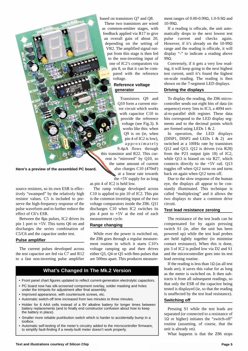
Here’s a preview of the assembled PC board.
• Front panel chart figures updated to reflect current-generation electrolytic capacitors.
• PC board now has silk-screened component overlay, solder masking and holes under the trimpots for adjustment after final assembly.
• Improved appearance, with countersunk screws, etc.• Automatic switch-off time increased from two minutes to three minutes.
• Holder for 6 AAA cells instead of a 9V alkaline battery for longer times between battery replacements (and to finally end constructor confusion about how to keep the battery in place).
• Smaller more reliable pushbutton switch which is harder to accidentally bump in a toolbox.
• Automatic self-testing of the meter’s circuitry added to the microcontroller firmware, to simplify fault-finding if a newly-built meter doesn’t work properly.
What’s Changed In The Mk.2 Version

making measurements and switches itspin 2 port to 0V, in turn switching offtransistor Q2. Then, when you releaseS1, Q1 switches off and the meter shutsdown.
In addition, the ESR Meter includes anautomatic power-off function. This shutsthe meter down if it has been idle formore than three minutes.
It works like this: as long as the meteris actively taking readings, it keeps reset-ting a 3-minute timer function in the Z86microcontroller. However, if the unit isleft idle (even with the test leads touch-ing), the Z86 automatically switches itspin 2 port low after three minutes, thusturning off the power.
This automatic switch-off functionmay be a nuisance in some situations,however. Hence, it can be easily disabledif necessary (see the “OptionalModifications” panel on page 12.
Battery voltage warning
A simple voltage divider consisting oftrimpot VR1 and series resistors R25 &R26 makes up the battery warning cir-cuit. This divider is connected across theswitched battery voltage and VR1 isadjusted so that it applies 2V to pin 9 ofIC2 when the battery voltage is at 7V (ie,the minimum at which the regulator willcontinue to regulate).
Pin 9 of IC2 is the non-inverting inputof IC2’s second internal comparator. Inoperation, IC2 switches its pin 4 port to0V for a period of 100ms several timesper second, to allow C10 to charge up toa predictable 2V. The second comparatorinside IC2 then compares this 2V refer-ence against the voltage on VR1’s wiper.
If the battery voltage is down to 7V,IC2 reduces the time each LED display isswitched on by 50%. This reduces theload, which allows the battery voltage toslightly rise again and provide a bit moreoperating time. It also flashes a “b” onthe righthand digit at a 1Hz rate until thepower is turned off.
Protection circuitry
Last but not least, the meter needs tobe protected against being connected tocharged capacitors. This protection ispartially provided by back-to-backdiodes D3 and D4. If an external DCvoltage (ie, a charged capacitor) is con-nected, one of these diodes conducts andforces non-polarised capacitors C5 andC6 to charge up to that voltage.
Additional protection is provided byC7, R12, D5 & D6 which stop excessiveinput voltages from damaging transistorsQ7 and Q8 in the pulse amplifier circuit.
In particular, diodes D5 & D6 acts asvoltage clamps – D5 ensures that thevoltage on Q7’s base cannot go above5.6V, while D6 ensures that this voltagecannot go below -0.6V.
Finally, extra “heavy-duty” protectioncan be added by connecting a pair ofback-to-back high-power diodes (notshown on the circuit) between the testterminals. The “Optional Modifications”panel on page 12.
Construction
Even if the ESR Meter’s operationseems complicated, at least it’s easy tobuild. As you can see in the photos, allthe components except for the batteryholder, test sockets and the pushbuttonswitch are mounted on a single PCboard. This in turn is attached to the frontpanel using spacers and machine screws.
The very first thing to do is glue thedisplay window to the inside of the frontpanel, using a few drops of an adhesivesuch as contact cement around its edges.This can then be put aside to dry whileyou assemble the PC board.
Although a high-quality, solder-masked PC board is supplied, it’s stillwise to check it for defects. To do this,illuminate the component side with abright light and examine the copper sidevery carefully – preferably with a magni-fier – for any hairline fractures in thetracks. Check also for any solder“whiskers” or bridges and pay particularattention to any tracks which passbetween IC socket pads, where suchdefects tend to congregate and hide.
Because of the need to make it fit intoa compact plastic case, the PC board istightly packed and the solder pads arequite small. The last thing this circuitneeds is solder bridges and bad joints, sobe very careful with your soldering.Always lift the iron vertically from ajust-soldered joint and never wipe it side-ways as so many constructors seem todo!
Construction is easiest if you begin by
installing the resistors and diodes first.Note that the kit for the Mk.2 versioncontains 1% resistors. It’s notoriouslydifficult to correctly identify the colourbands on these, so check each one’svalue with an ohmmeter before solderingit to the board. Table 1 will help youselect the resistor values prior to check-ing.
The larger components can now all beinstalled. These parts include crystalXTAL1, the electrolytic capacitors, trim-pots VR1 & VR2, the transistors, and thesockets for the LED displays and IC2 &IC3.
Note particularly that the 7-segmentLED displays and LEDs are mounted ona 28-pin IC socket. Make sure that thissocket is flat on the PC board before sol-dering its pins, otherwise the displayswill foul the Perspex window when youlater attempt to fit the front panel.
As usual, take care with the orientationof the polarised components; ie, the elec-trolytic capacitors, diodes and transis-tors. You should also make sure that thedifferent transistor types all go in theircorrect places. Don’t install the socketedparts just yet, though.
Once everything’s on the PC board,hold the component side up to a brightlight and carefully check for any solderbridges or other problems. In particular,check for light shining through the holesof unsoldered joints (this has been anoth-er common cause of problems with thiskit).
LED displays
Now for the LEDs and the 7-segmentLED displays. First, cut the leads of thetwo decimal point LEDs down to about8mm-long, then gently push them intotheir places in the 28-pin socket. Makesure that they are correctly oriented; ie,the flat side of each LED must go to theright – see Fig.6.
Next, insert the two 7-segment dis-plays, ensuring that their decimal pointsare at the bottom and that they are prop-
Text and illustrations courtesy of Silicon ChipPage 6
So what are typical ESR readings for various electrolytic capacitors? Unlike otherelectrical characteristics, there’s no such thing as a “normal” ESR value for an elec-trolytic of a given capacitance and operating voltage. The ESR to a large extentdepends on the physical size of the capacitor and whether it’s a low-ESR or hightemperature-rated type. It also varies between manufacturers. In addition, ESRincreases rapidly as the temperature drops and vice versa.The chart on the front of the meter contains sample ESR values for a range of common electrolytic capacitor values and voltage ratings. These have beenderived both from physical measurements on a range of capacitors and from manufacturer’s data sheets. It’s only intended as a rough guide, to give an idea ofwhat to expect until you become familiar with using the ESR meter.
What Are Typical ESR Readings?

erly seated. It might be necessary to snipa bit off their leads to get them to sit flaton the socket.
External wiring
When all the components are on theboard, solder two 150mm lengths ofhookup wire to the battery pads on thePC board - red to “+” and black to “-”.
The pushbutton switch terminals andtest lead sockets are quite close to the PCboard once everything has been mountedon the front panel. As a result, you canconnect them to the PC board using thetin copper wire supplied. Alternatively,you can use short lengths of the suppliedhookup wire.
Solder these leads to the PC board now
but don’t connect them to the switch ortest sockets for the time being.
Initial checks
With IC2 and IC3 still out of theirsockets, connect the supply leads to thebatteries (or a 9V DC power supply),with a milliammeter in series with one ofthe supply leads.
Initially, you shouldn’t see any currentbeing drawn. Now short the pushbuttonswitch wires (the righthand ones whenlooking at the front) and check that thecurrent drawn is now about 6mA. If it’ssignificantly higher or lower, start look-ing for assembly errors (componentplacement errors, missed solder jointsand solder splashes).
Assuming the current checks OK, con-nect the negative lead of a voltmeter tothe negative battery lead, then check thatthere’s +5V on pin 5 of IC2’s socket andon pin 16 of IC3’s socket.
If everything’s OK to here, disconnectthe 9V supply and the milliammeter.That done, discharge any static electrici-ty you may have accumulated by touch-ing something earthed, then install IC2(Z86E0412PSC) and IC3 (4094) in theirsockets. Double-check to ensure thatthese are both oriented correctly – theirindented pin 1 ends are to the left.
Next, set both VR1 and VR2 to theirmid-range positions, then separate thepushbutton switch leads and reconnectthe 9V supply. Now short the pushbuttonleads again and keep them shorted.
At this point, you should see some-thing on the 7-segment LED displays,preferably “-” on the lefthand one. Afterfive seconds, the displays should blankfor a moment as the microcontroller doesa basic check of the circuitry. If the nextthing you see is “.8.8” for two seconds, itmeans that the board has passed the testsand is probably OK.
However, if you see an “F” on the left-hand display and a digit or “A” on therighthand one, the microcontroller has
Text and illustrations courtesy of Silicon Chip Page 7
1 PC board, code ZA1044, 95 x 57mm1 3.58MHz crystal1 16-pin IC socket1 18-pin IC socket1 28-pin IC socket1 4 x AAA cell holder1 2 x AAA cell holder1 plastic utility box1 miniature momentary-contact push
button switch2 4mm banana sockets1 pre-punched silk-screened front
panel1 red perspex display filter4 15mm spacers6 PC pins1 10kΩ PC-mount trimpot (VR1)1 200Ω PC-mount trimpot (VR2)
Semiconductors4 1N4148 or 1N914 signal diodes
(D1,D2,D5,D6)2 1N4004 power diodes (D3,D4)4 BC328 PNP transistors (Q1,
Q3,Q4,Q5)5 BC338 NPN transistors (Q2,
Q6,Q11,Q12,Q13)1 BC548 NPN transistor (Q7)3 BC558 PNP transistors (Q8,
Q9,Q10)1 78L05 3-terminal regulator (IC1)1 Z86E0408 or Z86E0412
programmed microcontroller (IC2)1 4094 / MC14094 CMOS shift
register (IC3)
2 LSD5114 or LTS5503AE 7-segment LED displays (DISP1, DISP2)
2 3mm orange LEDs (LED1,LED2)
Capacitors2 220µF 16V RB electrolytic (C3,C9)1 100µF 16V RB electrolytic (C1)1 47µF 50V bipolar RB electrolytic
(C6)1 22µF 16/25V RB electrolytic (C8)1 470nF 63V MKT (C10)4 100nF 50V disc or monolithic
(C2,C4,C5,C13)1 33nF 63V MKT (C7)2 27pF 50V NPO disc ceramic
(C11,C12)
Resistors (0.25W, 1% unless specified)1 470kΩ 4 2.2kΩ1 220kΩ 2 1kΩ1 100kΩ 1 680Ωσ2 47kΩ 1 220Ω2 15kΩ 1 180Ω7 10kΩ 1 100Ω1 6.8kΩ 1 68Ω (for calibration)
3 4.7kΩ 1 5.6Ω 5% (for calibration)
1 2.7kΩ
MiscellaneousHookup wire, tinned copper wire, solder, flat washers, black counter-sunk selftap screws (No.4 x 6mm),black counter-sunk pan head screws(M3 x 6mm), double sided tape, heat-shrink tubing, test leads & instructions.
Parts List
Fig.7: the PC board is attached to the underside of the front panel using 15mm-long tapped spacers, flat washers and M3x 6mm machine screws.

detected a problem. In that case, go to the“Fault Codes” panel to find out what tocheck for.
At this point, you can mount the testlead sockets onto the front panel – seeFig.7. Note that plastic insulating rings
are supplied with these sockets. Asshown in Fig.7, these must be installedbetween the lugs and the front panel, notunder the tops of the sockets. Many con-structors of the Mk.1 version overlookedthis and placed the lugs directly on the
metal panel, thereby short-circuitingthem! Also refer to Fig.11 for correctsocket mounting.
Next, mount the pushbutton switch,using small pliers to gently tighten thenut and being careful not to slip andscratch the panel. That done, fasten thestandoffs to the board using 3mmscrews, then mount the whole assemblyon the front panel using the black coun-tersunk 3mm screws supplied. If theLED displays foul the Perspex window,use the supplied washers to further spacethe board from the front panel.
Finally, complete the assembly by con-necting the wires to the pushbuttonswitch and test lead sockets, and by sol-dering the supply leads to the batteryholder. See Fig.10a & 10b.
Calibration
Now for the calibration. The step-by-step procedure is as follows:
(1) Plug in the test leads, then push thebutton. You should see “-” on the left-hand display, indicating that the meter isseeing an ESR/resistance that’s greater
Text and illustrations courtesy of Silicon ChipPage 8
Value 4-Band Code (1%) 5-Band Code (1%)
470kΩ yellow violet yellow brown yellow violet black orange brown220kΩ red red yellow brown red red black orange brown100kΩ brown black yellow brown brown black black orange brown47kΩ yellow violet orange brown yellow violet black red brown15kΩ brown green orange brown brown green black red brown10kΩ brown black orange brown brown black black red brown6.8kΩ blue grey red brown blue grey black brown brown4.7kΩ yellow violet red brown yellow violet black brown brown2.7kΩ red violet red brown red violet black brown brown2.2kΩ red red red brown red red black brown brown1kΩ brown black red brown brown black black brown brown680Ω blue grey brown brown blue grey black black brown220Ω red red brown brown red red black black brown180Ω brown grey brown brown brown grey black black brown100Ω brown black brown brown brown black black black brown68Ω blue grey black brown blue grey black gold brown5.6Ω green blue gold brown green blue black silver brown
Table 1: Resistor Colour Codes
Fig.6: Install the parts on the PC board as shown here but don’t install IC2 or IC3 until after the initial checks described inthe text have been made.

Text and illustrations courtesy of Silicon Chip Page 9
Fig.8: you will need tomake up this simplecircuit to set the bat-tery warning trip point(7V). Alternatively, youcan use an existingvariable power supply.Note, componentsshown not supplied inkit.
Fig.11: The front panel is mountedbetween the plastic collar and ring ofthe banana socket. Then two nuts areused to hold and lock the assembly inplace.
threaded
metal
insert
plastic
collarfront
panel
plastic
ringwasher
solder
lugnuts
File here
Fig.12: The milled Perspex window should be of snug fit inside the frontpanel cut-out. At times, paint over-spray on the inner edge of the cut-outmay prevent the window from fitting correctly. If this occurs it will be nec-essary to file smooth the vertical milled edge until a perfect fit is achieved.Finally, a small drop of contact adhesive at each corner of the display willhold and secure the window in place.
BOB....9/95
+-
47uF BP
78
L0
5
10k
4.7
k
15k
47
k
2.2k
10k
2.2k
1k
2.2k
100R
22
0R
1k
100k
220k
2.2k
18
0R
6.8k
680R
10
k
10
k
10k
470k
10k
10k
47k
15k
4.7k
4.7k
100uF
100nF
220uF
100nF
10
0n
F3
3n
22uF
470nF
27pF 27pF
10
0n
F
IC2
Z86E0412
IC34094
DIS1
LSD 5114
VR110KVR2
200R
LED1 LED2
3.58MHz
BC328
BC328
BC328
BC338
BC
55
8
BC558
BC338
BC338
BC338
BC328
BC338
BC
54
8
BC
55
8
41
48
RadioRCS
4148 Radio
RC
S
1N
41
48
Radio RCS
4148 Radio
RC
S
220uF
1N40042
.7k
DIS2
o
CAP ON TEST BUTTON
-
BATT
LSD 5114
XTAL1
1N4004
ka ka
BOB....9/95
+-
IC2
IC3
DIS1
VR1VR2
LED1 LED2
XTAL1
RadioRCS
Radio
RC
S
Radio RCS
Radio
RC
S
DIS2
o
CAP ON TEST BUTTON
+-
BATT
Q13
Q12
C3
Q5
R27
R28C4
R10
Q4
C13
R9
R7
R5
R8
Q3
R6
Q6 R24
D3
D4C9
R11
C6
C11 C12
R19
R20
C10
Q10
Q11
Q9
R18
C5
R15
R13
R21
R22
D2
R3
R29
C8
Q7 Q8
R17
R26
Q2
R12
D5
R16
C2
R23
R14
D6
C7
IC1
C1
Q1R25
R1
R2
D1
R4
kaka
Fig.9a & 9b: Shows the PCB overlay with both component values and component designations. This can be very helpfulin a service or fault-finding situation when the constructor needs to cross-reference between the two.
Overlay by component value Overlay by component designation

than its maximum reading of 99Ω.(2) Short the test leads together. The
meter will display their resistance, typi-cally 0.2-0.5Ω. Pushing the button againwith the leads shorted should change thedisplay to “.00” as the meter zeros outtheir resistance. However, it’s normal forthis reading to change a bit, due to varia-tions in contact resistance between theprobes (remember that we’re measuringhundredths of one ohm!).
(3) Connect the supplied 68Ω 1% cali-bration resistor to the probes and careful-ly adjust VR2 until the meter reads “68”.That done, check that it reads the sup-plied 5.6Ω calibration resistor reasonablyaccurately.
Battery warning setup
Skip this bit if you disabled the auto-matic switch-off function by leaving onelead of R25 disconnected (see the“Optional Modifications” section).
This adjustment is easiest if you haveaccess to a variable DC power supply. Ifnot, you’ll need to temporarily build thelittle circuit shown in Fig.8. The adjust-ment procedure is as follows:
(1) With the meter off, unplug the testleads and turn VR1 fully anti-clockwise(as viewed from the copper side of thePC board).
(2) Adjust the supply voltage to 7.0V,then switch the meter on.
(3) Slowly turn VR1 clockwise untilth0d the “b” battery warning indicationbegins flashing on the righthand display.
(4) Turn the meter off, wind the powersupply back up to 9V, then switch themeter back on and check that the batterywarning triggers when you drop the sup-ply back to 7.0V.
And that’s it! If everything went asplanned, you can fully assemble yournew ESR meter and start finding defec-tive electrolytic capacitors. But first, readthe panel entitled “Driving The ESRMeter Mk.2” – it not only contains use-ful hints but list the precautions that mustbe followed as well.
Text and illustrations courtesy of Silicon ChipPage 10
-+
4 x 'AAA'
Battery Holder
+ -
2 x 'AAA'
Battery Holder
-ve
+ve
to
PCB
bend across
terminal and
solder
solder hook-up
wire to battery
terminals
9V
battery holder to PCB
solder & insulate with
heatshrink tubing
Fig.10a: Two battery holders connected in series are used for the battery source.Connect and solder the inner terminals as shown, then solder a short length ofhook-up wire to each of the outer terminals completing the positive (+ve) andnegative (-ve) supply leads.
Fig.10b: Bend the battery terminals on the 4 x ‘AAA’ holder at 90 degrees andsolder a short length of black hook-up wire to the negative (-ve) terminal. A pieceof heatshrink tubing can be used to insulate the solder joint. Now bend the pos-itive (+ve) terminal across and solder to the adjacent (-ve) terminal of the 2 x‘AAA’ battery holder. Further details are shown above in Fig.10a.
This is what the underside of thefront panel looks like, prior to fittingthe PC board. The Perspex windowcan be secured using contactcement.

Text and illustrations courtesy of Silicon Chip Page 11
WWhat if it doesn’t work? In
that case, the Mk.2 ESRMeter’s firmware allows
the microcontroller to do somebasic testing of the electronics, tohelp you narrow down a problem toone area of the board.Before doing the self-test, it’s very
important to first set VR1 to the cen-tre of its adjustment range andmake sure that the meter’s supplyvoltage is in the range of 8.5-9.5V.Now switch the meter on by press-
ing and continuing to hold the but-ton down, regardless of what thedisplays are showing. After five sec-onds, they’ll go blank for a moment,then show a test result for two sec-onds. The meter will then switch off by itself after you release thebutton.If everything is more or less OK,
you’ll see “.8.8” on the displays (thisshows that all the display segmentsand decimal point LEDs are work-ing). However, if the microcontrollerhas detected a major problem, it willflash a fault code consisting of an“F” on the lefthand display and acharacter from 0-9 or an “A” on therighthand one.Experience has shown that by far
the most common cause of ESRmeter kits not working properly isdefective soldering. When a faultcode directs you to a particular partof the circuit, carefully check (usinga bright light and magnifier) for sol-der whiskers, non-soldered jointsand track damage such as lifted sol-der pads.If you can’t see anything abnormal,
start checking for incorrect compo-nents and component placementerrors such as transistors of thewrong type or with their leads in thewrong holes. If that doesn’t show upanything, you might have receiveda defective component in the kit,though this is very rare.OK, here’s a list of what the fault
codes indicate:F0: Q11 is not discharging C10.
Check around Q11 (BC338), R21(10kΩ), R22 (470kΩ) and pin 4 ofIC2 (Z86E0412).F1: C10 is charging too quickly.
Check that R22 really is 470kΩ andthat R19 & R20 are 10kΩ. Makesure C10 is 470nF (0.47µF, code“474”). Check also for soldering andcom-ponent placement problemsaround transistors Q9 & Q10(BC558).F2: C10 is charging too slowly (or
not at all). Check around Q9, Q10(BC558), R22 (470kΩ), R19 & R20(10kΩ) and C10 (470nF).F3: Pulse amplifier output bias
<440mV (ie, at collector of Q8).Check R13 (100kΩ) & R14 (220kΩ)for correct values and check that D6isn’t reversed. Check around Q7(BC548), Q8 (BC558) and aroundpin 8 of IC2 plus associated compo-nents.F4: Pulse amplifier output bias
>1V. Carry out the same checks asfor “F3” code. Check also that D5isn’t reversed.F5: A test current source is perma-
nently on. Check area around Q3,Q4 & Q5 (all BC328); R5, R7 & R9(2.2kΩ); and pins 15, 16 & 17 ofIC2.F6: No output from pulse amplifier.
This fault is usually due to thebanana sockets being installed with+rt-circuiting them (see Fig.7). Ifthat’s not the problem, checkaround C7 (33nF), R12 (1kΩ), D3 &D4 (1N4002), C5 (100nF) and C6(47µF bipolar).F7: Q3 not sourcing current. Check
around Q3 (BC328), R5* (2.2kΩ),R6 (10kΩ) and pin 15 of IC2.F8: Q4 not sourcing current. Check
around Q4 (BC328), R7* (2.2kΩ),R8 (1kΩ) and pin 16 of IC2.F9: Q5 not sourcing current. Check
around Q5 (BC328), R9* (2.2kΩ),R10 (100Ω), IC2 pin 17.FA: Q6 not switching on. Check
around Q6 (BC338), R24 (10kΩ)and pin 1 of IC2.Obviously, the microcontroller
can’t perform detailed tests onevery component, so it’s possiblethat your meter is malfunctioningeven though the self-testing hasn’tshown up a problem.For example, if the meter is behav-
ing strangely, “freezing” up or givingabsurd readings on some values oftest resistors, the most likely causeis a mix-up in the values of R6(10kΩ), R8 (1kΩ) and R10 (100Ω).On the other hand, if the meter pro-
duces readings but there’s some-thing wrong with the displayed char-acters, this is almost certainly dueto one or more solder bridgesbetween the pins of the large sock-et holding the displays, or aroundIC3.If the meter doesn’t stay switched
on when you push the button, checkaround Q2 (BC338), R3 (15kΩ),R29 (2.7kΩ) and pin 2 of IC2. If itswitches off when you short the testleads, R2 (4.7kΩ) may be the incor-rect value or Q1 (BC328) may havea low current gain.Finally, if you can’t get the meter
into the test mode, zero it or switchit off, check for solder “whiskers”and open circuits around pin 3 ofIC2, R4 (47kΩ) and D2.
If none of the above has helpedyou to identify the problem, there’sa page of fault-finding informationon my website: http://members.ozemail.com.au/
~bobpar/esrprob.htm.Do a Google search for “ESR
meter faultfinding” if you can’t find it.Also Ben Cook in Perth will get
your meter working for a reason-able fee plus postage and handling.You can contact him at:[email protected].
* The R5/7/9 area of the boardseems to be a “magnet” for solder bridges and whiskers.
CCCCCChhhhhheeeeeecccccckkkkkk TTTTTThhhhhheeeeeesssssseeeeee FFFFFFaaaaaauuuuuullllll tttttt CCCCCCooooooddddddeeeeeessssss IIIIII ffffff IIIIII tttttt DDDDDDooooooeeeeeessssssnnnnnn’’’’’’ tttttt WWWWWWoooooorrrrrrkkkkkk

Text and illustrations courtesy of Silicon ChipPage 12
OOOOOOpppppptttttt iiiiiioooooonnnnnnaaaaaallllll MMMMMMooooooddddddiiiiii ffffff iiiiiiccccccaaaaaatttttt iiiiiioooooonnnnnnssssss
Heavy-duty protectionTo provide greater protection
against connection to charged elec-trolytics, some kit builders haveconnected an inverse-parallel pairof 1N5404 (or similar) high-powerdiodes between the test lead sock-ets. So if you’re the kind who’s like-ly to connect the meter to the120µF input filter capacitor of a240V-powered switching powersupply without checking that it’sbeen properly discharged, thismodification is for you.
Reportedly, this protects themeter quite well, although it canresult in the probe tips being blownoff by large charged capacitors.The resulting surge current canalso damage the charged capacitorand the power diodes themselves.
However, without the diodes, theresulting >600A current spikedestroys the microcontroller (IC2)and damages C6.
Improving battery lifeIf you’d like to get even more bat-
tery life out of the meter (and arefeeling a bit adventurous), you canreplace IC1 (78L05) with anLP2950CZ-5.0 and replace R26(10kΩ) with a 27kΩ resistor. Thatdone, adjust trimpot VR1 so thatthe low battery warning triggers at5.6V instead of the original 7.0V.(Thanks to G. Freeman, SouthAustralia for this idea which waspublished in the August 1998 issue of “Electronics Australia” magazine).
Disabling automaticswitch-off
If you’d like to power the meterfrom an external 9V DC supply andhave it operating continuously, justdisconnect one end of R25 (47kΩ).This disables the automatic switch-off function but note that the lowbattery warning will no longer workif you do this.
Of course, you can easily recon-nect R25 if you change your mindin the future.
For more modifications, includinga buzzer to help you discriminatebetween good and bad electrolyticswithout having to look at the meter,go to my ESR Meter Hints webpage at
http://members.ozemail.com.au/~bobpar/esrhints.htm
Screw CSKM3 x 6mm
Screw CSKM3 x 6mm Screw CSK
No4 x 6mm
Screw CSKNo4 x 6mm
Battery Holders
Doube-sided tape
CaseScrew PHM3 x 6mm
Screw PHM3 x 6mm
Fig.13: the battery holder is positioned on the bottom of the case and held in place by double sided tape.

Text and illustrations courtesy of Silicon Chip Page 13
DDDDDDrrrrrr iiiiiivvvvvviiiiiinnnnnngggggg TTTTTThhhhhheeeeee EEEEEESSSSSSRRRRRR MMMMMMeeeeeetttttteeeeeerrrrrr MMMMMMkkkkkk......222222
TThe ESR Meter is extremelysimple to operate but thereare a few precautions to fol-
low. First, here’s its basic step-by-step operation:(1). Insert the plugs of the test leadsinto their sockets.(2). Press the button so the “-” sym-bol appears on the display.(3). Hold the test probes tightlytogether – the test lead resistance isdisplayed.(4). With the probes still together,press the button again to give azeroed reading of “.00”. You canrepeat this at any time.(5). Measure the capacitor’s ESR (itshould be discharged first). A read-ing of “-” indicates a reading greaterthan 99Ω.(6). When you’ve finished measur-ing, press the button with theprobes separated. The meterswitches off when you release thebutton.(7). When the battery is getting low,“b” flashes once per second and thedisplay dims to conserve theremaining battery capacity.
Precautions(1). Beware charged capacitors:the very first thing to do is to makecertain that the equipment you’ll beusing the ESR Meter on is discon-nected from all power. Most elec-trolytic capacitors will be dischargedby the circuitry around them within afew seconds of the power beingswitched off. However, be warnedthat filter capacitors in power sup-plies can remain dangerouslycharged, especially if there’s a fault.Before using the meter, make sure
that all power supply capacitors arefully discharged. You can do thisusing well-insulated probes thatinclude a series 100Ω 5W or similarpower resistor. Don’t justshort the capacitor’s termi-nals together; it can notonly damage the capacitorbut can also be dangerous.Always allow several sec-
onds to ensure a completedischarge. Apart from therisk of surprise and injury toyou, large charged capaci-tors can seriously damage
the meter. If you think your ESRmeter might be accidentally con-nected to electrolytics that arecharged to high voltages, considerthe extra protection idea describedin the “Optional Modifications”panel.(2). Watch out for interference: the meter can produce unsteadyindications if its test leads pick upstrong horizontal deflection signalvoltages. To avoid this, be sure tokeep it away from operating (CRT)TVs and monitors when makingmeasurements.(3). Use straight test leads: don’tuse self-retracting “curly” test leadswith your meter. Their inductancecan cause measurement errors.Also, be very careful not to confusethe ESR Meter’s test leads withthose from your multimeter! Keepthem well separated.
What else can it do?Since publication of the Mk.1
design in 1996, I’ve received a lot offeedback from imaginative ESR Meter users regarding otheruses for it. The full list is on my web-site at http://members.ozemail.com.au/
~bobpar/esrhints.htm but here aresome of the best ones:(1). Resistance Measurement: asstated previously, this meter is real-ly an AC ohmmeter with an equiva-lent test frequency of about 100kHzand capable of measuring non-inductive resistances from 0.01Ω to99Ω. As such, it can be useful forlocating short circuits on PC boardsby showing the resistance of a cop-per track decreasing or increasingas you approach or move awayfrom the short. For example, this isuseful when trying to identify whichone in a paralleled set of power
transistors is shorted (thanks MikeDiack).You can also make your own very
low-value resistors by measuringout a length of nichrome or similarresistance wire to give the requiredresistance. In addition, the ESRMeter can be used to check thecontact resistance of switches, con-nectors and relays.Just remember that any significantamount of inductance will causemeasurement errors. You can’tmeasure the DC resistance of achoke, transformer winding, videohead or a roll of electrical cable, forexample.(2). Basic Signal Generator: themeter’s test signal is a 500mV P-P(open circuit) burst of 8ms pulses ata 2kHz rate, repeated several timesper second. As a result, it can beused as a signal source for basicchecks on amplifiers, loudspeakersand other audio components(thanks Joe Lussy).
MaintenanceThe meter’s readings might becomeunsteady after a lot of use, due tooxidation or loosening of the testlead sockets. Heavily spray the testlead plugs with contact cleaner ofthe kind which evaporates com-pletely (eg, CRC “CO” ContactCleaner), then repeatedly insert andwithdraw them from their socketsbefore it dries. If the test lead sock-ets have become loose, gently re-tighten them with long needle-nosepliers.If the test probes have developed aresistive layer of oxidation, givethem a wipe with a tissue soaked intuner cleaner like CRC 2.26 or sim-ilar (thanks Joe Sopko).

Text and illustrations courtesy of Silicon Chip Dick Smith Electronics © ZA8819 - 1
A.B.N. 34 000 908 716P.O. Box 500 Regents Park DC, NSW 2143
WEBSITE: www.dse.com.auPH: (02) (lnt 612) 9642 9100 Fax: (02) 9642 9111
IIIIIIddddddeeeeeennnnnntttttt iiiiii ffffffyyyyyyiiiiiinnnnnngggggg DDDDDDeeeeeeffffffeeeeeecccccctttttt iiiiiivvvvvveeeeee EEEEEElllllleeeeeecccccctttttt rrrrrroooooollllllyyyyyytttttt iiiiiiccccccssssss
IIf you’re getting the idea that it’stricky to identify defective elec-trolytics, relax! Experience has
shown that in almost every case, acapacitor’s ESR needs to rise to atleast 10 times its normal value tocause a circuit malfunction. Often,you’ll find that it’s risen to >30 timesits normal value, or is so high thatthe meter just displays “-” (ie,>99Ω). So, with few exceptions, theelectrolytic capacitor(s) causing afault will be very obvious.It’s for this reason that the front
panel figures don’t need to beextremely accurate or complete.When you encounter an electrolyticwhose value or voltage isn’t on thechart, it’s sufficient to assume thatits ESR should be similar to that ofa capacitor adjacent to it on thechart.If you have any doubts, it’s best to
compare the meter’s reading on asuspect capacitor with that of a newcapacitor of the same value andvoltage rating.Note that the electrolytics which
fail are often the ones that are closeto heat-generating componentssuch as power semiconductors andresistors, so check these first. It willsave time if you mark each goodcapacitor with a felt-tipped pen asyou go, so you know which onesstill need to be checked.
Traps to avoidAll test equipment can produce
misleading indications under someconditions and the ESR Meter is nodifferent. Because it is basically ahigh-frequency AC ohmmeter, itcan’t discriminate between acapacitor with a very low ESR andone which is short-circuit or veryleaky.In general, electrolytics with high
ESR will cause faults such asswitching power supplies losingregulation or failing to start, high-frequency noise in signal circuits,and distorted scanning waveformsin monitors and TV sets. In vintageequipment, they can cause humand low frequency instability(“motorboating”), etc.Conversely, leaky or shorted
capacitors are likely to disturb theDC conditions of the circuit they arein, producing quite different kinds offaults. Tests with a multimetershould locate these. That said, inseveral decades of working onelectronic gear, I’ve encounteredless than a dozen shorted elec-trolytics but hundreds with highESR)!If you find an electrolytic giving an
ESR reading which seems toogood (low) to be true, disconnect itfrom the circuit and measure itsresistance with an ohmmeter – itmight be short-circuit. In fact JohnRobertson from “John’s Jukes” inCanada found that a cheap digitalmultimeter on a low ohms rangecan be connected in parallel withthe ESR Meter without them dis-
turbing each other. Doing thisallows the multimeter to show upthose rare shorted electrolyticswhile you simultaneously check theESR.In some circuits such as in com-
puter motherboards, switchingpower supplies and TV/monitordeflection stages, electrolyticcapacitors are connected directly inparallel. In that case, a good capac-itor can make the ESR of a (paral-lel) bad one appear to be muchlower than it really is. You need tobe aware of the circuit your suspectcapacitor is in and disconnect itfrom circuit before making a meas-urement if necessary.
Beware Of Good ESR WithReduced Capacitance!There’s one more failure mode that
you need to be aware of: when theESR remains perfectly OK but thecapacitance has dropped by a largeamount. This is apparently quiterare but when it does happen, it cancause a lot of confusion.
If your ESR Meter shows that allthe electrolytics seem OK but somestrange fault is still present. try dis-connecting and checking eachcapacitor in turn with capacitancemeter. Alternatively, you could trytemporarily connecting new capaci-tors inparallel with anysuspect units(after turning the power off and dis-charging them).