assessment and management of ageing of major nuclear … · availability of design functions...
TRANSCRIPT

IAEA-TECDOC-1471
Assessment andmanagement of ageing of major
nuclear power plant componentsimportant to safety:
BWR pressure vessel internals
October 2005

IAEA SAFETY RELATED PUBLICATIONS
IAEA SAFETY STANDARDS
Under the terms of Article III of its Statute, the IAEA is authorized to establish or adopt standards of safety for protection of health and minimization of danger to life and property, and to provide for the application of these standards.
The publications by means of which the IAEA establishes standards are issued in the IAEA Safety Standards Series. This series covers nuclear safety, radiation safety, transport safety and waste safety, and also general safety (i.e. all these areas of safety). The publication categories in the series are Safety Fundamentals, Safety Requirementsand Safety Guides.
Safety standards are coded according to their coverage: nuclear safety (NS), radiation safety (RS), transport safety (TS), waste safety (WS) and general safety (GS).
Information on the IAEA’s safety standards programme is available at the IAEA Internet site
http://www-ns.iaea.org/standards/
The site provides the texts in English of published and draft safety standards. The texts of safety standards issued in Arabic, Chinese, French, Russian and Spanish, the IAEA Safety Glossary and a status report for safety standards under development are also available. For further information, please contact the IAEA at P.O. Box 100, A-1400 Vienna, Austria.
All users of IAEA safety standards are invited to inform the IAEA of experience in their use (e.g. as a basis for national regulations, for safety reviews and for training courses) for the purpose of ensuring that they continue to meet users’ needs. Information may be provided via the IAEA Internet site or by post, as above, or by e-mail to [email protected].
OTHER SAFETY RELATED PUBLICATIONS
The IAEA provides for the application of the standards and, under the terms of Articles III and VIII.C of its Statute, makes available and fosters the exchange of information relating to peaceful nuclear activities and serves as an intermediary among its Member States for this purpose.
Reports on safety and protection in nuclear activities are issued in other publications series, in particular the Safety Reports Series. Safety Reports provide practical examples and detailed methods that can be used in support of the safety standards. Other IAEA series of safety related publications are the Provision for the Application of Safety Standards Series, the Radiological Assessment Reports Series and the International Nuclear Safety Group’s INSAG Series. The IAEA also issues reports on radiological accidents and other special publications.
Safety related publications are also issued in the Technical Reports Series, the IAEA-TECDOC Series, the Training Course Series and the IAEA Services Series, and as Practical Radiation Safety Manuals and Practical Radiation Technical Manuals.Security related publications are issued in the IAEA Nuclear Security Series.

IAEA-TECDOC-1471
Assessment andmanagement of ageing of major
nuclear power plant componentsimportant to safety:
BWR pressure vessel internals
October 2005

The originating Section of this publication in the IAEA was:
Engineering Safety Section International Atomic Energy Agency
Wagramer Strasse 5 P.O. Box 100
A-1400 Vienna, Austria
ASSESSMENT AND MANAGEMENT OF AGEING OF MAJOR NUCLEAR POWER PLANT COMPONENTS IMPORTANT TO SAFETY:
BWR PRESSURE VESSEL INTERNALS IAEA, VIENNA, 2005 IAEA-TECDOC-1471 ISBN 92–0–109205–9
ISSN 1011–4289 © IAEA, 2005
Printed by the IAEA in Austria October 2005

FOREWORD
At present, there are over four hundred operational nuclear power plants (NPPs) in
IAEA Member States. Operating experience has shown that ineffective control of the ageing degradation of the major NPP components (caused for instance by unanticipated phenomena and by operating maintenance or manufacturing errors) can jeopardize plant safety and also plant life. Ageing in these NPPs must be therefore effectively managed to ensure the availability of design functions throughout the plant service life. From the safety perspective, this means controlling, within acceptable limits, the ageing degradation and wareout of components important to safety so that adequate safety margins remain, i.e. integrity and functional capability in excess of normal operating requirements.
This TECDOC is one in a series of guidance reports on the assessment and management of ageing of the major NPP components important to safety. The reports are based on experience and practices of NPP operators, regulators, designers, manufacturers, and technical support organizations and a widely accepted Methodology for the Management of Ageing of NPP Components Important to Safety, which was issued by the IAEA in 1992. Since the reports are written from a safety perspective, they do not address life or life cycle management of plant components, which involves economic considerations.
The current practices for the assessment of safety margins (fitness for service) and the inspection, monitoring and mitigation of ageing degradation of selected components of heavy water moderated reactors (HWRs), boiling water reactors (BWRs), pressurized water reactors (PWRs), and water moderated, water cooled energy reactors (WWERs) are documented in the reports. These practices are intended to help all involved directly and indirectly in ensuring the safe operation of NPPs, and also to provide a common technical basis for dialogue between plant operators and regulators when dealing with age related licensing issues. The guidance reports are directed at technical experts from NPPs and from regulatory, plant design, manufacturing and technical support organizations dealing with specific plant components addressed in the reports.
The report addresses the reactor pressure vessel internals in BWRs. Maintaining the structural integrity of these reactor pressure vessel internals throughout NPP service life, in spite of several ageing mechanisms, is essential for plant safety.
The work of all contributors to the drafting and review of this publication, identified at the end, is greatly appreciated. In particular, the IAEA would like to acknowledge the contributions of J.P. Higgins, M. Erve, J. Pachner, J. Hakala, B. Kastner, C. Dillmann, T. Mulford and Y. Motora. The IAEA officer responsible for this report was T. Inagaki of the Division of Nuclear Installation Safety.

EDITORIAL NOTE
The use of particular designations of countries or territories does not imply any judgement by the publisher, the IAEA, as to the legal status of such countries or territories, of their authorities and institutions or of the delimitation of their boundaries.
The mention of names of specific companies or products (whether or not indicated as registered) does not imply any intention to infringe proprietary rights, nor should it be construed as an endorsement or recommendation on the part of the IAEA.

CONTENTS
1. INTRODUCTION.......................................................................................................... 1
1.1. Background ........................................................................................................... 1 1.2. Objective ............................................................................................................... 2 1.3. Scope ..................................................................................................................... 3 1.4. Structure ................................................................................................................ 3 References to Section 1................................................................................................... 4
2. DESCRIPTION OF RPVIS ........................................................................................... 5
2.1. Description ............................................................................................................ 6 2.1.1. Core plate ................................................................................................ 6 2.1.2. Core plate ∆P/standby liquid control (SLC) line .................................... 6 2.1.3. Core spray piping .................................................................................... 6 2.1.4. Core spray sparger................................................................................... 7 2.1.5. Reactor water cleanup (RWCU) return sparger ...................................... 7 2.1.6. Control rod guide tube ............................................................................ 7 2.1.7. CRD Housing .......................................................................................... 7 2.1.8. Feedwater sparger ................................................................................... 8 2.1.9. In-core housing........................................................................................ 8 2.1.10. Internal recirculation pump ..................................................................... 8 2.1.11. Jet pump .................................................................................................. 9 2.1.12. LPCI coupling ....................................................................................... 10 2.1.13. Neutron source holders ......................................................................... 10 2.1.14. Orificed fuel support ............................................................................. 10 2.1.15. Core shroud ........................................................................................... 10 2.1.16. Core shroud head................................................................................... 11 2.1.17. Core shroud head bolts.......................................................................... 11 2.1.18. Core shroud support .............................................................................. 11 2.1.19. Steam dryer ........................................................................................... 12 2.1.20. Steam separators.................................................................................... 12 2.1.21. Thermal shield....................................................................................... 12 2.1.22. Surveillance capsule holder................................................................... 12 2.1.23. Top guide .............................................................................................. 13
2.2. Materials .............................................................................................................. 34 2.3. Classification for importance to safety................................................................ 34
3. DESIGN BASIS, CODES, STANDARDS AND REGULATIONS ........................... 40
3.1. Requirements in the USA.................................................................................... 40 3.2. Requirements in Germany................................................................................... 41 3.3. Requirements in Japan......................................................................................... 42 3.4. Requirements in Finland ..................................................................................... 42 3.5. Requirements in Switzerland............................................................................... 42 References to Section 3................................................................................................. 42
4. OPERATING CONDITONS ....................................................................................... 43
4.1. Neutron exposure and electrochemical corrosion potential ................................ 43 4.2. Primary coolant chemistry specification ............................................................. 44 References to Section 4................................................................................................. 49

5. AGEING MECHANISMS........................................................................................... 50
5.1. Embrittlement...................................................................................................... 50 5.1.1. Description of radiation embrittlement ................................................. 51 5.1.2. Description of thermal ageing embrittlement ....................................... 50 5.1.3. Significance of embrittlement ............................................................... 51
5.2. Fatigue ................................................................................................................. 52 5.2.1. Description ............................................................................................ 52 5.2.2. Significance of fatigue .......................................................................... 53
5.3. Stress corrosion cracking..................................................................................... 54 5.3.1. IGSCC ................................................................................................... 54 5.3.2. IASCC ................................................................................................... 57 5.3.3. Significance of SCC.............................................................................. 58
5.4. General corrosion ................................................................................................ 60 5.4.1. Description ............................................................................................ 60 5.4.2. Significance of general corrosion.......................................................... 61
5.5. Erosion corrosion ................................................................................................ 61 5.5.1. Description ............................................................................................ 61 5.5.2. Significance of erosion corrosion.......................................................... 61
5.6. Mechanical wear.................................................................................................. 62 5.6.1. Description ............................................................................................ 62 5.6.2. Significance of wear.............................................................................. 62
5.7. Operational experience........................................................................................ 62 5.7.1. Core plate .............................................................................................. 63 5.7.2. Core spray internal piping..................................................................... 64 5.7.3. Core spray sparger................................................................................. 64 5.7.4. Control rod guide tube .......................................................................... 64 5.7.5. CRD housing......................................................................................... 64 5.7.6. In-core housing..................................................................................... 64 5.7.7. Jet pump................................................................................................ 64 5.7.8. LPCI coupling ....................................................................................... 65 5.7.9. Orificed fuel support ............................................................................. 65 5.7.10. Core shroud ........................................................................................... 65 5.7.11. Shroud support ...................................................................................... 66 5.7.12. Top guide .............................................................................................. 66
5.8. Conclusion of significance of ageing mechnisms ............................................... 67 References to Section 5................................................................................................. 69
6. INSPECTION, MONITORING, MAINTENANCE AND REPLACEMENT............ 71
6.1. Inspection and monitoring methods .................................................................... 71 6.1.1. Inspection .............................................................................................. 71 6.1.2. Monitoring............................................................................................. 71
6.2. National requirements on inspection................................................................... 72 6.2.1. USA....................................................................................................... 72 6.2.2. Germany................................................................................................ 76 6.2.3. Japan...................................................................................................... 80 6.2.4. Finland................................................................................................... 80 6.2.5. India....................................................................................................... 80
6.3. Current inspection and maintenance practices .................................................... 81 6.3.1. Core plate .............................................................................................. 81 6.3.2. Core spray internal piping..................................................................... 81

6.3.3. Core spray sparger................................................................................. 82 6.3.4. CRD housings ....................................................................................... 82 6.3.5. In-core housings .................................................................................... 83 6.3.6 Jet pump ................................................................................................ 83 6.3.7. Core shroud ........................................................................................... 84 6.3.8. Core shroud support .............................................................................. 85 6.3.9. Top guide .............................................................................................. 85
6.4. Repair and replacement ....................................................................................... 85 6.5. National and international R&D programmes..................................................... 86 References to Section 6................................................................................................. 88
7. AGEING ASSESMENT METHODS.......................................................................... 90
7.1. Fatigue ................................................................................................................. 90 7.1.1. Fatigue usage......................................................................................... 90
7.2. Stress corrosion cracking..................................................................................... 91 References to Section 7................................................................................................. 92
8. MITIGATION METHODS.......................................................................................... 93
8.1. Mitigation via water chemistry control ............................................................... 93 8.1.1. Hydrogen water chemistry .................................................................... 94 8.1.2. Noble Metal Chemical Application (NMCA)....................................... 94 8.1.3. Deposition of noble metals by plasma spray......................................... 95
8.2. Mitigation via surface treatment.......................................................................... 95 8.2.1. Residual stress improvement by Peening.............................................. 95 8.2.2. Laser de-sensitization treatment............................................................ 95
References to Section 8................................................................................................. 96
9. RPVI AGEING MANAGEMENT PROGRAMME.................................................... 97
9.1. Key elements of the ageing management programme ........................................ 99 9.1.1. Understanding ageing............................................................................ 99 9.1.2. Coordination of the ageing management programme........................... 99 9.1.3. Operational aspects ............................................................................. 100 9.1.4. Inspection, monitoring and assessment............................................... 100 9.1.5. Maintenance, mitigation, repair and replacement ............................... 101
9.2. Application guidance......................................................................................... 101 9.2.1. Fatigue................................................................................................. 102 9.2.2. Stress corrosion cracking .................................................................... 102 9.2.3. Flaw evaluation ................................................................................... 102
References to Section 9............................................................................................... 103
ABBREVIATIONS.............................................................................................................. 105
CONTRIBUTORS TO DRAFTING AND REVIEW ......................................................... 107


1. INTRODUCTION
1.1. Background Managing the safety aspects of nuclear power plant (NPP) ageing requires implementation of effective programmes for the timely detection and mitigation of ageing degradation of plant systems, structures and components (SSCs) important to safety, so as to ensure their integrity and functional capability throughout plant service life. General guidance on NPP activities relevant to the management of ageing (operation, maintenance, examination and inspection of SSCs) is given in the International Atomic Energy Agency (IAEA) Nuclear Safety Standards (NUSS) Code on the Safety of Nuclear Power Plants: Operation Requirements [1.1] and associated Safety Guide on Maintenance, Surveillance and In-service Inspection in Nuclear Power Plants [1.2], hereinafter the MS&I Safety Guide.
The Operation Requirements require that an NPP operating organization prepare and carries out a programme of maintenance, testing, surveillance and inspection of plant SSCs important to safety to ensure that their level of reliability and effectiveness remains in accordance with the design assumptions and intent and that the safety status of the plant has not been adversely affected since the commencement of operation. This programme is to take into account the operational limits and conditions, any other applicable regulatory requirements, and be re-evaluated in the light of operating experience. The associated Safety Guide provides further guidance on NPP programmes and activities that contribute to timely detection and mitigation of ageing degradation of SSCs important to safety.
The MS&I Safety Guide [1.2] provides recommendations on methods, frequency and administrative measures for the in-service inspection programme for critical systems and components of the primary reactor coolant system aimed at detecting possible deterioration caused by stressors such as stress, temperature, radiation, vibration and water chemistry and at determining whether they are acceptable for continued safe operation of the plant or whether remedial measures are needed. Organizational and procedural aspects of establishing and implementing an NPP programme of preventive and remedial maintenance to achieve design performance throughout the operational life of the plant are also covered in the MS&I Safety Guide [1.2]. The MS&I Safety Guide also provides guidance and recommendations on surveillance activities for SSCs important to safety (i.e. monitoring plant parameters and systems status, checking and calibrating instrumentation, testing and inspecting SSCs, and evaluating results of these activities). The aim of the surveillance activities is to verify that the plant is operated within the prescribed operational limits and conditions, to detect in time any deterioration of SSCs as well as any adverse trend that could lead to an unsafe condition, and to supply data to be used for assessing the residual life of SSCs. The MS&I Safety Guide provides general guidance, but does not give detailed technical advice for particular SSCs.
Programmatic guidance on ageing management is given in Technical Reports Series No. 338 Methodology for the Management of Ageing of Nuclear Power Plant Components Important to Safety [1.3] and in a Safety Practice Publication Data Collection and Record Keeping for the Management of Nuclear Power Plant Ageing [1.4]. Guidance provided in these reports served as a basis for the development of component specific technical documents (TECDOCs) on the Assessment and Management of Ageing of Major NPP Components Important to Safety. This publication on boiling water reactor (BWR) reactor pressure vessel internals is one of such TECDOCs. TECDOCs already issued address: steam generators [1.5], concrete containment buildings [1.6], CANDU pressure tubes [1.7], PWR
1

reactor pressure vessels [1.8], PWR reactor vessel internals [1.9], metal components of BWR containment systems [1.10], in-containment I&C cables [1.11], CANDU reactor assemblies [1.12], and primary piping in PWRs [1.13].
The function of the reactor pressure vessel Internals (RPVIs) may divided into safety and non-safety functions. The safety functions are to support the core under all loading conditions, maintain a coolable geometry, assure control rod insertion times, assure reactivity control, direct and contain emergency cooling flows, assure availability of monitoring instruments and allow recovery to safe shutdown conditions. The added non-safety functions are to channel the incoming feedwater flow to the fuel, separate the water and steam providing dry steam to the turbine and recirculating the saturated water after mixing it with the feedwater and providing support for operational instrumentation and surveillance sample holders. The initial commercial BWR was Dresden 1 in the early 1960s. All subsequent BWR internal designs evolved from that design.
Boiling water reactors are operating in Finland, Germany, India, Japan, Mexico, Russian Federation, Spain, Sweden, Switzerland, Taiwan (China), and the United States of America. The history of commercial boiling water reactor internals throughout the world is one of safe operation. The reactor internals are designed to withstand steady state and fluctuating forces produced under handling, normal operation, transient and accident conditions. The load restriction and fatigue life on as fabricated reactor internals are governed by code or regulatory bodies throughout the world. The reactor internals are subjected to neutron irradiation as well as exposure to the primary coolant. The radiation and service condition or environment must be taken into consideration when assessing and managing ageing of the reactor internals.
As operating experience demonstrated the need for better control of the materials and fabrication, the internals materials were subjected to more restrictive chemistry requirements and testing including resistance to inter-granular attack, control of carbon, cobalt and other elements. The fabrication was restricted to eliminate processes that sensitized the material. In addition record requirements were expanded. Further, once an NPP is in operation, the reactor vessel internals are subjected to periodic in-service inspection for flaws developed during service.
BWR RPVIs experience service at 100°C–300°C and some of them in the core region are subject to significant levels of fast neutron fluence. The primary materials of construction have been austenitic stainless steel in various types and grades including stabilized material, Ni-Cr-Fe Alloys and weld metals. Product forms include bar, plate, castings and forgings.
1.2. Objective The objective of this report is to identify significant ageing mechanisms and
degradation locations, and to document the current practices for the assessment and management of the ageing of BWR RPVIs. The report emphasizes safety aspects and also provides information on current inspection, monitoring and mitigation practices for managing ageing of BWR RPVIs.
The underlying objective of this report series is to ensure that the information on the current assessment methods and ageing management techniques is available to all involved, directly and indirectly, in the operation of NPPs in IAEA Member States. The target
2

audience includes NPP operators, regulators, technical support organizations, designers, and manufacturers.
The readers who are not interested in technical details related to ageing degradation of BWR RPVIs but are interested in ageing management strategy for BWR RPVIs utilizing a systematic ageing management approach should go directly to Section 9. This section presents a strategy for managing each of the two significant ageing mechanisms: fatigue and stress corrosion cracking.
1.3. Scope This report deals with age related degradation and ageing management of BWR
RPVIs. It presents and discusses the requirements and methodologies utilized for the assessment and management of ageing of BWR RPVIs.
This report provides the technical basis for understanding and managing the ageing of the BWR RPVIs to ensure that the acceptable safety and operational margins are maintained throughout the plant service life. The scope of the report includes RPVI components important to safety. RPVIs which are not considered important to safety are described and categorized but are not evaluated for ageing management. Consumables such as fuel bundles and control rods are not treated in this document.
This report primarily reflects RPVIs design, operating, inspection and refurbishment experience for BWRs designed by GE (General Electric) Nuclear Energy and other BWR suppliers (ABB ATOM, Hitachi, Siemens, Toshiba), as well as engineering and service companies (Tecnatom). Evaluations are provided for reactor internal components, with the boundary of evaluation being the attachment or penetration weld connecting the internal component to the RPV (reactor pressure vessel). The RPV and other components such as neutron monitors are outside the scope of this report.
1.4. Structure The design, materials of construction, safety function and safety classification of each
RPVI component are described in Section 2. In Section 3 applicable regulatory requirements and industry codes and standards are addressed. Section 4 deals with operation conditions. Section 5 presents degradation mechanisms, susceptible degradation sites, their significance, and operating experience. Section 6 addresses the application of various inspection, monitoring, maintenance and replacement technologies. Section 7 gives the current practices and methods for assessment of specific degradation mechanisms. Section 8 details current practices and methods for mitigation of specific degradation mechanisms. This report concludes, in Section 9, with a description of a systematic ageing management programme for BWR RPVIs.
3

REFERENCES TO SECTION 1
[1.1.] INTERNATIONAL ATOMIC ENERGY AGENCY, Safety of Nuclear Power
Plants: Operation, Safety Standards Series No. NS-R-2, IAEA, Vienna (2000). [1.2.] INTERNATIONAL ATOMIC ENERGY AGENCY, Maintenance, Surveillance
and In-Service Inspection in Nuclear Power Plants, Safety Standard Series No. NS-G-2.6, IAEA, Vienna (2002).
[1.3.] INTERNATIONAL ATOMIC ENERGY AGENCY, Methodology for Management of Ageing of Nuclear Power Plant Components Important to Safety, Technical Reports Series No. 338, IAEA, Vienna (1992).
[1.4.] INTERNATIONAL ATOMIC ENERGY AGENCY, Data Collection and Record Keeping for the Management of Nuclear Power Plant Ageing, Safety Series No. 50-P-3, IAEA, Vienna (1991).
[1.5.] INTERNATIONAL ATOMIC ENERGY AGENCY, Assessment and Management of Ageing of Major Nuclear Power Plant Components Important to Safety: Steam Generators, IAEA-TECDOC-981, IAEA, Vienna (1997).
[1.6.] INTERNATIONAL ATOMIC ENERGY AGENCY, Assessment and Management of Ageing of Major Nuclear Power Plant Components Important to Safety: Concrete Containment Buildings, IAEA-TECDOC-1025, IAEA, Vienna (1998).
[1.7.] INTERNATIONAL ATOMIC ENERGY AGENCY, Assessment and Management of Ageing of Major Nuclear Power Plant Components Important to Safety: CANDU Pressure Tubes, IAEA-TECDOC-1037, IAEA, Vienna (1998).
[1.8.] INTERNATIONAL ATOMIC ENERGY AGENCY, Assessment and Management of Ageing of Major Nuclear Power Plant Components Important to Safety: PWR Pressure Vessels, IAEA-TECDOC-1120, IAEA, Vienna (1999).
[1.9.] INTERNATIONAL ATOMIC ENERGY AGENCY, Assessment and Management of Ageing of Major Nuclear Power Plant Components Important to Safety: PWR Vessel Internals, IEAE-TECDOC-1119, IAEA, Vienna (1999).
[1.10.] INTERNATIONAL ATOMIC ENERGY AGENCY, Assessment and Management of Ageing of Major Nuclear Power Plant Components Important to Safety: Metal Components of BWR Containment Systems, IAEA-TECDOC-1181, IAEA, Vienna (2000).
[1.11.] INTERNATIONAL ATOMIC ENERGY AGENCY, Assessment and Management of Ageing of Major Nuclear Power Plant Components Important to Safety: In-containment Instrumentation and Control Cables, Volume I and II, IAEA-TECDOC-1188, IAEA, Vienna (2000).
[1.12.] INTERNATIONAL ATOMIC ENERGY AGENCY, Assessment and Management of Ageing of Major Nuclear Power Plant Components Important to Safety: CANDU Reactor Assemblies, IAEA-TECDOC-1197, IAEA, Vienna (2001).
[1.13.] INTERNATIONAL ATOMIC ENERGY AGENCY, Assessment and Management of Ageing of Major Nuclear Power Plant Components Important to Safety: Primary Piping in PWRs, IAEA-TECDOC-1361, IAEA, Vienna (2003).
4
2. DESCRIPTION OF RPVIS
Section 2.1 provides the overall system description of BWR RPVIs including design features. Section 2.2 shows applicable material specifications. Section 2.3 provides classification of RPVIs for importance to safety. Today’s operating BWR RPVIs were mainly designed and manufactured by ABB (now Westinghouse Atom AB), GE Nuclear Energy, Hitachi Ltd., Siemens (now Framatome ANP), Toshiba Co..
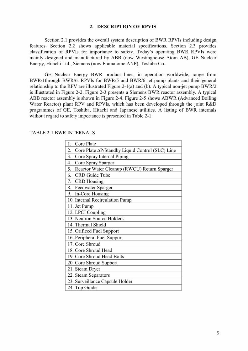
GE Nuclear Energy BWR product lines, in operation worldwide, range from BWR/1through BWR/6. RPVIs for BWR/5 and BWR/6 jet pump plants and their general relationship to the RPV are illustrated Figure 2-1(a) and (b). A typical non-jet pump BWR/2 is illustrated in Figure 2-2. Figure 2-3 presents a Siemens BWR reactor assembly. A typical ABB reactor assembly is shown in Figure 2-4. Figure 2-5 shows ABWR (Advanced Boiling Water Reactor) plant RPV and RPVIs, which has been developed through the joint R&D programmes of GE, Toshiba, Hitachi and Japanese utilities. A listing of BWR internals without regard to safety importance is presented in Table 2-1.
TABLE 2-1 BWR INTERNALS
1. Core Plate 2. Core Plate ∆P/Standby Liquid Control (SLC) Line 3. Core Spray Internal Piping 4. Core Spray Sparger 5. Reactor Water Cleanup (RWCU) Return Sparger 6. CRD Guide Tube 7. CRD Housing 8. Feedwater Sparger 9. In-Core Housing 10. Internal Recirculation Pump 11. Jet Pump 12. LPCI Coupling 13. Neutron Source Holders 14. Thermal Shield 15. Orificed Fuel Support 16. Peripheral Fuel Support 17. Core Shroud 18. Core Shroud Head 19. Core Shroud Head Bolts 20. Core Shroud Support 21. Steam Dryer 22. Steam Separators 23. Surveillance Capsule Holder 24. Top Guide
5

2.1. Description
2.1.1. Core plate The core plate consists of a circular plate with round openings. The core plate
provides horizontal support and guidance for the control rod guide tubes, incore flux monitor tubes, peripheral fuel supports, and startup neutron source holders. The last two items are also supported vertically by the core plate. The entire assembly is bolted to a support ledge in the core shroud. The core plate also forms a portion within the core shroud, which causes the recirculation flow to pass into the orificed fuel support and through the fuel assemblies.
The main components of the core plate are the top plate, rim, support beams, and tie rods as illustrated in Figure 2-6. Support beams and tie rods were used for plate support for all plant designs with the exception of BWR/6 and ABWR where the tie rod was eliminated and replaced by additional grid support beams.
2.1.2. Core plate ∆P/standby liquid control (SLC) line The core plate differential pressure (∆P)/standby liquid control (SLC) line as shown
in Figure 2-7 serves a dual function to provide a path for the injection of the liquid control solution (sodium pentaborate) to shut down the reactor from full power when reactivity control with control rods is not possible, and to sense the differential pressure across the core plate. This line enters the reactor vessel at a point below the core shroud as two concentric pipes (for BWR/6 a separate line in the bottom head). In the lower plenum, the two pipes separate. The inner pipe terminates near the lower core shroud with a perforated portion below the core plate. It is used to sense the pressure below the core plate during normal operation and to inject a liquid control solution if required. The outer pipe terminates immediately above the core plate and senses the pressure in the region outside the fuel assemblies.
The core plate dP line instrumentation provides information on core flow performance for diagnostic purposes, and on core spray piping break. The ABWR design has only the core and internal pump differential pressure lines. The standby liquid control solution injection is served by the high pressure core flooder sparger. The core delta P lines, with an open top end, penetrate and terminate immediately above and below the core plate to sense the pressure during normal operation. The internal pump delta P lines terminate inside and outside the core shroud and sense the pressure across the pump during normal operation.
The Siemens BWR uses the core plate differential pressure line only for measurement purposes, whereas a separate standby liquid control line for safe shut down is injecting concentrated boron solution from a storage tank via the feedwater lines into the reactor pressure vessel for neutron absorption.
The ABB design has no separate core plate. CRD guide tube top pieces are squares and these squares form the core plate.
2.1.3. Core spray piping Core spray piping inside the RPV as shown in Figure 2-8 provides the flow path of
coolant, which cools the fuel during a postulated loss-of-coolant accident (LOCA). The internal core spray piping is fabricated from stainless steel and connects to the RPV nozzle and to the core spray sparger in the upper core shroud for distribution into the core.
6

In Siemens/KWU-plants (except Würgassen), the core spray system may exist but is not necessary, as they are not equipped with external recirculation lines. Due to this, no large leaks or breaks can occur below the core level. Maximum leak sizes to be postulated in the lower part of the RPV can be controlled in these plants by the emergency core cooling system.
2.1.4. Core spray sparger The core spray sparger, shown in Figure 2-9, is fabricated from stainless steel pipe.
The upper sparger has bottom-mounted nozzles; the lower sparger has top-mounted nozzles. Core spray spargers provide uniform distribution of the flow from core spray piping to shower all fuel bundles to assure long-term core cooling when the core cannot be reflooded.
The ABWR design has the high pressure core flooder (HPCF) sparger which is located inside the top guide. The HPCF sparger provides high pressure core cooling and a higher flow at low pressure.
2.1.5. Reactor water cleanup (RWCU) return sparger In BWR/1 plants, the cleanup return sparger distributes the water from the RWCU
system in the vessel. The sparger is connected to the RPV nozzle, to which the RWCU system return line joins. Water from the system enters below the steam separator and mixes with reactor recirculating water. The sparger is fabricated from stainless steel pipe and has holes in the front.
2.1.6. Control rod guide tube The control rod guide tube extends from the top of the control rod drive (CRD)
housings up through holes in the core plate above the core plate. The control rod guide tubes, control rod drive (CRD) housings and RPV stub tubes (shown in Figure 2-10) provide an assembly of components at symmetric locations below the core which support the weight of the fuel (except for some peripheral bundles supported by the core plate) and allow the movement of control rods into and out of the reactor core to achieve reactivity control.
2.1.7. CRD Housing The CRD housings are fabricated from an austenitic stainless steel and inserted
through the control rod drive penetrations in the vessel bottom head and welded to the stub tubes. [Figure 2-11 (a) and (b)]
Each housing transmits loads to the bottom head. These loads include the weights of a control rod, a control rod drive, a control guide tube, an orificed fuel support, and the four fuel assemblies that rest on the fuel support. The lower portion of CRD housings are primary pressure boundaries.
Note that the stub tube is categorized as the reactor pressure vessel and is not within the scope of this report.
7

2.1.8. Feedwater sparger The feedwater sparger distributes the feedwater uniformly within the reactor to form
a homogeneous mixture with the reactor recirculating coolant water. The feedwater is injected through spargers located below the steam separator assembly, which form a ring made up of two, four or six segments, depending upon plant-specific design details.
The feedwater is distributed and mixed with the recirculating saturated water discharged from the steam separators and dryers to provide subcooling at the inlet to the jet pump or internal/ external pump to prevent cavitation and to have a uniform temperature mixture entering the reactor core to prevent an asymmetrical core power distribution.
The High Pressure Coolant Injection (HPCI) System injects water through the feedwater line into the feedwater sparger to maintain high reactor water level in the event of an accident. Even if the feedwater sparger contained cracks, the flow rate from the HPCI System into the vessel annulus region would remain the same. Thus, even though the HPCI System uses the feedwater sparger for discharge, sparger integrity is not needed to protect the fuel.
In Siemens BWRs, both, high and low pressure coolant injection systems feed water from the pressure suppression pool into the reactor pressure vessel either via the feedwater line or via separate nozzles directly connected to the feedwater spargers.
In the ABWR design, three of the feedwater spargers deliver and distribute ECCS flooding flow.
2.1.9. In-Core Housing In-core housings are fabricated from austenitic stainless steel and provide a path for
the neutron monitoring system detectors to access inside the reactor core. Each in-core housing is inserted through the in-core penetration in the bottom head and is welded to the inner surface of the bottom head. An in-core guide tube is welded to the top of each housing and a neutron flux monitor is bolted to the seal/ring flange at the bottom of the housing as shown in Figure 2-12. The in-core housings from the RPV penetration to the flange outside the vessel are part of the reactor vessel pressure boundary.
Recent GE designs and the ABWR design utilize horizontal stabilizers above the housing to RPV attachment weld to alleviate flow-induced vibration concerns due to increased lower plenum velocities.
2.1.10. Internal recirculation pump German BWR plants (except NPP Würgassen), most ABB plants beginning with
Forsmark and ABWR are not equipped with recirculation lines. Internal recirculation pumps are mounted to the pump nozzles at the lower part of the RPV as shown in Figure 2-3, 2-4(a) and 2-5. The hydraulic part of the pumps (impeller and distributor) is located inside the RPV between core shroud and RPV wall. The internal recirculation pumps are vertical, single stage axial pumps with speed control.
The plants developed by KWU (Siemens) have pumps of a twin-bearing design and are equipped with a two-stage gland system to the pressure-retaining boundary, which
8

employs hydrodynamic mechanical seals and one emergency seal (check seal or N2-actuated standstill seal).
The recirculation pump essentially consists of:
• Seal housing with hydrodynamic graphite bearing
• Shaft gland system with hydrodynamic mechanical seals and emergency seal
• Combined oil-lubricated thrust and journal bearing
• Variable-speed drive.
The ABB internal pumps plants and ABWR use a seamless wet motor internal pump design. Each pump is equipped with a heat exchanger for cooling and a purge flow that flows to the RPV to prevent crud intrusion.
2.1.11. Jet pump Jet pumps are stainless steel and nickel base alloy assemblies, which provide coolant
flow to the reactor core for forced convection cooling. Each jet pump assembly consists of seven major subassemblies. These are the recirculation riser, two inlet mixers, two hold-down beams, and two diffusers. A typical jet pump assembly is illustrated in Figure 2-13.
Recirculated water flows downward into the annular region between the vessel wall and the core shroud. A portion of this flow is drawn from the vessel by external recirculation pumps for use as jet pump drive flow. Each jet pump pair is driven by flow from the riser pipe. The recirculation pumps deliver this driven flow at high pressure through the risers to headers which distribute it evenly to jet pump nozzles. The remaining suction flow enters the jet pump at the suction inlet and becomes entrained by the driven flow from the jet pump nozzles. The two flows mix in the jet pump throat with some pressure increase, which is produced to drive the required flow through the reactor core and steam separators.
Riser
The riser connects the jet pump to the RPV recirculation inlet nozzle and provides the flow path, which directs the high-pressure driven flow upward from the vessel nozzle and divides the flow equally between the two jet pumps connected to each riser. The riser includes an elbow at the inlet, a vertical section of pipe with a restraint bracket attached near the midsection, two riser support braces and a transition casting.
Inlet mixer
The inlet mixer is attached to the riser and diffuser with brackets which provide structural support and accommodate differential thermal expansion between the vessel and the jet pump. The inlet section directs the flow downward and creates the high velocity jet necessary for entrainment of the suction flow.
The entire inlet mixer subassembly is designed for replacement, and can be disconnected from the diffuser, riser, and hold-down beam subassemblies.
9

Earlier Jet pumps had a single nozzle but BWR/6 and some BWR/5 plants use a five hole nozzle for improved efficiency.
Hold down beam (Jet-pump beam)
The jet pump hold-down beam provides a clamping force on each inlet to resist the elbow and nozzle hydraulic reaction forces. The riser and the inlet are firmly held together by a clamping jet pump hold-down beam placed across the top of each inlet.
Diffuser
The jet pump diffuser is welded to the core shroud support plate and designed to recover static head from the available kinetic energy.
2.1.12. LPCI coupling In GE BWR/5 and BWR/6 plants, the LPCI (low pressure coolant injection) sub-
system constitutes a portion of the emergency core cooling system. The LPCI restores and, if required, maintains the coolant inventory in the RPV after a loss-of-coolant accident by injecting water directly inside the core shroud. The LPCI coupling is a sleeve connection which accommodates the thermal expansion mismatch between the RPV and the core shroud as shown in Figure 2-14.
2.1.13. Neutron source holders During the initial plant operating cycle, there are several antimony-beryllium startup
sources located within the core. The purpose of these sources is to provide additional neutrons during initial startup. They are positioned vertically in the reactor in the upper grid and a hole in the lower core support plate. The compression of a spring at the top of the housing exerts a loading on the source. Though anchored firmly in place, the sources can easily be removed, but they need not be disturbed during refueling. The active source material is entirely enclosed in the stainless steel holder. Neutron sources and neutron source holders are normally removed after the first fuel cycle.
2.1.14. Orificed fuel support The orificed fuel supports (OFS) are stainless steel castings which rest on the top of a
control rod guide tube as shown in Figure 2-10. Each OFS supports the weight of four (4) fuel bundles.
In BWR/2 plants the fuel support casting is welded to the guide tube. The fuel orifice is attached to the fuel support by a bayonet connection.
2.1.15. Core shroud The core shroud separates the upward flow of coolant through the reactor core from
the downward recirculation flow. The core shroud is an assembly of cylinders fabricated from rolled and welded stainless steel plate material, which encompasses the reactor core as shown in Figure 2-15. For the replaced core shrouds of Japanese BWRs and the ABWR core shrouds, a forged ring material is used to decrease the weld lines. Typical core shroud weld locations are shown in Figure 2-15. Shell sections are normally solution heat treated, cold formed and joined with longitudinal and circumferential welds. The steam separator/shroud
10

head is bolted to the core shroud flange. The bottom of the core shroud is welded to an Alloy 600 core support cylinder or to a stainless steel shroud support ring. In Siemens plants, the top guide and core plate support rings are manufactured from forgings, which are longitudinally welded and stress relieved.
Structurally, the core shroud provides support for the top guide, core plate, and core support structure. The core shroud also supplies lateral restraint to hold the reactor core in place. The top guide and core plate are fastened to support ledges, which are part of the core shroud. Typically, peak end of life fluence levels for the middle of core shroud are on the order of 1 x 1025 n/m2 (E>1MeV).
2.1.16. Core shroud head Typically, the core shroud head is a dome-shaped stainless steel structure, which is
attached to the core shroud top flange. The shroud head and steam separator assembly, which is welded to the shroud head, form the cover of the core discharge plenum region. The shroud head is bolted to the core shroud flange by the shroud head bolts. The steam separator standpipes are welded to openings in the shroud head which serve as the path for flow exiting the core region.
2.1.17. Core shroud head bolts The shroud head bolts fasten the shroud head and steam separator assembly to the
core shroud flange. The bolts are manufactured from Alloy 600 and stainless steel material. The bolts are spread equally about the shroud head flange. The purpose of the shroud head bolts is to secure the shroud head and steam separator assembly. The number of shroud head bolts varies with plant size.
2.1.18. Core shroud support The representative shroud support structure consists of the circular plate, cylinder and
legs and is made of Ni base alloy 600. GE BWR/2 has a cone type shroud support structure which does not have the circular plate, cylinder and legs. The shroud support plate is welded to the RPV and shroud support cylinder with Alloy 182 or 82. The shroud support legs are welded to the bottom head of the RPV and the shroud support cylinder with Alloy 182 or 82. The shroud support bears the weight of the top guide, core shroud, shroud head and steam separators, jet pumps, and core plate. The shroud support (illustrated in Figure 2-15) provides connection between the core shroud and the RPV and isolates the annular region between the core shroud and the RPV from the lower RPV plenum and forms part of the core coolant boundary needed to maintain the two-thirds core height coverage required for jet pump plants.
The shroud support plate in jet pump plants contains two access holes (manways that provide access to the lower plenum) that are covered by welded-in or bolted to the plate. The welded-in cover plates rest on a small ledge near the bottom edge of the access hole. Access hole covers are fabricated from Alloy 600 plate and are welded to the shroud support plate with Alloy 182 or 82 as shown in Figure 2-16. Some plants have replaced welded-in cover plates with those fixed with Alloy X-750 bolts and nuts to avoid the IGSCC of Alloy 182. In Siemens BWRs, the core shroud support is made of stabilized austenitic stainless steel. The shroud support is welded to the bottom head of the RPV. It is supplemented by the
11

downcomer bottom plate, which is shrunk into the lower section of the core shroud and supports the core shroud support against the inside wall of the reactor pressure vessel.
2.1.19. Steam dryer The function of the steam dryer is to dry the steam exiting from the steam separators.
The steam dryer is a stainless steel assembly mounted in the reactor vessel above the steam separator which forms the upper boundary of the wet steam plenum. Vertical guides on the inside of the vessel align the dryer during installation. The steam dryer ring supports the dryer on the dryer support brackets. In many BWR plants, the steam dryer support ring is a cold-formed section made of stainless steel. In other plants, the stainless steel steam dryer support ring was installed in a non-cold-worked condition.
Steam from the separator flows upward and outward through drying vanes. These vanes are attached to top and bottom supporting members to form a rigid, integral unit. Moisture is removed and carried off via troughs and drains to the downcomer surrounding the separators and then into the annular region between the core shroud and RPV inner wall.
2.1.20. Steam separators The steam separators consist of an array of stainless steel standpipes with a three-
stage moisture separator located at the top of each standpipe. The stainless steel steam separators are welded to the shroud head. The fixed axial flow type steam separators have no moving parts. In each separator the steam and water mixture rising through the standpipe impinges on vanes, which spin the two-phase mixture to establish a vortex wherein the centrifugal forces separate the water from steam in each of three stages. Steam leaves the separator at the top and passes into the wet steam plenum below the dryer. The separated water exits from the lower end of each stage of the separator and enters the pool that surrounds the standpipes to join the annulus flow.
2.1.21. Thermal shield In BWR-1 plants, a thermal shield is provided between the RPV wall and core shroud
to reduce the neutron radiation incident on the RPV wall. It is fabricated from stainless steel plates and typically has a thickness of one inch. The thermal shield is supported by thermal shield support brackets welded to the RPV wall. The height of the thermal shield is typically equal to the height of the active core and the gap between the thermal shield and the RPV wall is of the order of one inch. The RPV wall surveillance coupons are placed in the gap between RPV and the thermal shield.
2.1.22. Surveillance capsule holder The surveillance capsule holder is a stainless steel container, which houses RPV
surveillance specimen capsules used to monitor embrittlement due to neutron irradiation of the vessel shell. A bracket holds the surveillance capsule holder to the vessel wall. Capsule holders are removed with RPV surveillance specimens on a pre-planned basis in accordance with the plant surveillance plan.
12

2.1.23. Top guide The top guide maintains the horizontal position and spacing of the upper ends of the
fuel bundles. During normal operation, applied stress level for the top guide is ~1.5 MPa (<2 ksi). End of life neutron fluence levels for the top guide typically range from 5 x 1025 to 2 x 1026n/m2 (E>1MeV). Typically, the top guide consists of interlocking stainless steel beams which intersect to form a grid which attached to a stainless steel rim as illustrated in Figure 2-17. The beams have cutouts at the intersection points. The upper beams have cutouts on the lower portion while the lower beams have slots in the upper portion. The grid of beams forms square holes, which maintain alignment of control rods and fuel bundles during normal operation, pressure transients and seismic events.
Grid beams attach to a rim on the periphery of the top guide, usually by means of reinforcement blocks and pins which attach to the cover plate and bottom plate. The cover plate is attached to the rim with numerous pins or bolts, and the bottom plate is usually welded to the rim. (In some plants there is no cover plate, and the crossbeams are welded directly to the rim. In a few cases the bottom plate and rim are an integral machined piece). The rim, cover plate and bottom plate are fabricated from plate. In Siemens plants, the top guide is manufactured from longitudinally welded and stress relieved forgings which form a ring beam that is the load path for fuel lateral loads via the grid beams. GE BWR/2 through BWR/5 top guides are positioned by four vertical or horizontal aligner pins. Bosses or sockets are welded to both the top guide and the core shroud to engage the aligner pins. In GE BWR/6 reactors and ABWR, the top guide square holes for each fuel cell are machined out of a single piece of stainless steel which eliminates the crevice locations. BWR/6 and ABWR top guides are bolted in place along with the upper core shroud. Previous considerations regarding rim geometry, aligner pins, wedges, and the beam grid are not applicable to BWR/6 nor ABWR.
13
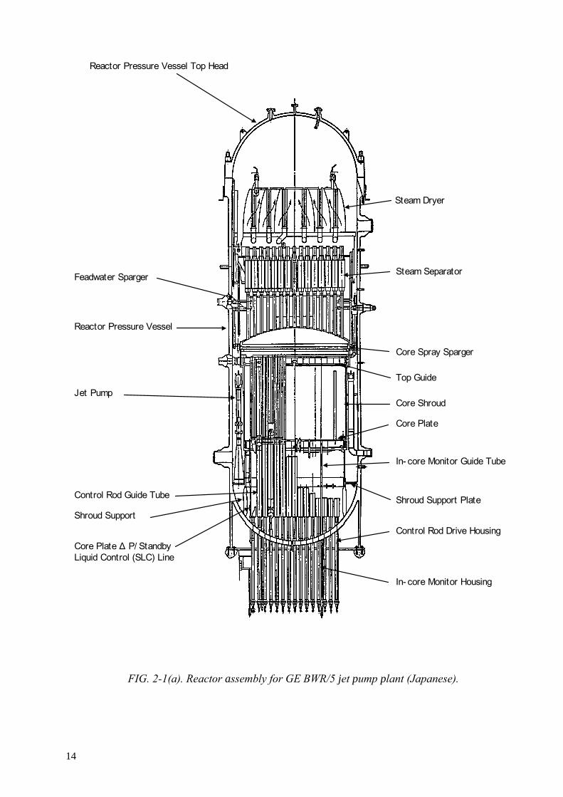
FIG. 2-1(a). Reactor assembly for GE BWR/5 jet pump plant (Japanese).
Steam Dryer
Steam Separator
Reactor Pressure Vessel Top Head
Feadwater Sparger
Reactor Pressure Vessel
Jet Pump
Control Rod Guide Tube
Shroud Support
Core Plate ∆ P/ Standby Liquid Control (SLC) Line
In- core Monitor Housing
Control Rod Drive Housing
Shroud Support Plate
In- core Monitor Guide Tube
Core Plate
Core Shroud
Top Guide
Core Spray Sparger
14

FIG. 2-1(b). Reactor assembly for GE BWR/6 jet pump plant.
15

FIG. 2-2. Reactor assembly for GE BWR-2 non-jet pump plant.
16

STEAM SEPARATOR ASSEMBLY
STEAM DRYER ASSEMBLY
SHROUD HEAD
TOP GUIDE
CORE SHROUD
CORE PLATE
DOWNCOMER BOTTOM PLATE
RECIRCULATION PUMP
CONTROL ROD DRIVE
IN-CORE FLUX MONITOR ASSEMBLY
CONTROL ROD GUIDE TUBE
FEEDWATER SPARGER
STEAM OUTLET NOZZLE
FEEDWATER INLET NOZZLE
FIG. 2-3. Siemens reactor assembly type 72.
17

FIG. 2-4 (a.) ABB reactor assembly of internal pump RPV (BWR 660).
Recirculatin Pump
18

FIG. 2-4 (b). ABB reactor assembly of external pump RPV (BWR 580).
REACTOR VESSEL HEAD
STEAM DRYER
STEAM SEPARATOR
FEED WATER SPARGER
CORE SHROUD HEAD
CORE GRID
CORE SHROUD
CONTROL ROD GUIDE TUBE
19
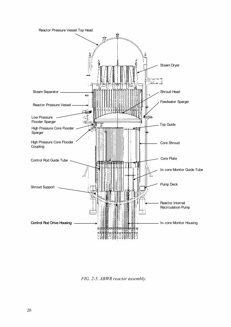
FIG. 2-5. ABWR reactor assembly.
Reactor Pressure Vessel Top Head
Steam Dryer
Shroud Head
Feedwater Sparger
High Pressure Core Flooder Coupling
Core Shroud
In- core Monitor Guide Tube
Pump Deck
Reactor Internal Recirculation Pump
In- core Monitor HousingControl Rod Drive HousingControl Rod Drive Housing
Shroud Support
Control Rod Guide Tube Core Plate
High Pressure Core Flooder Sparger
Low Pressure Flooder Sparger
Reactor Pressure Vessel
Steam Separator
Top Guide
20
RIM FABRICATION WELD
STIFFENER BEAMSTO CORE PLATE WELD
STABILIZERBEAM
PERIPHERAL FUEL SUPPORTTO CORE PLATE WELD
CORE PLATETO RIM WELD
STIFFENER BEAMTO STABILIZER ROD/BEAMWELD
STIFFENER BEAM TO RIM WELD
CORE PLATE RIM/SKIRT
CORE PLATESTIFFENER
IN-CORE GUIDE TUBE SUPPORTTO STABILIZER BEAM WELDS
FIG. 2-6. Core plate.
21
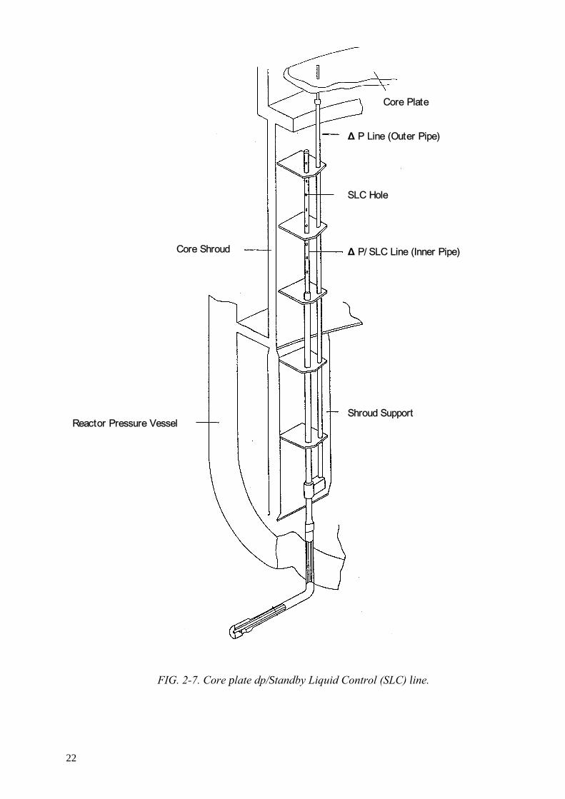
FIG. 2-7. Core plate dp/Standby Liquid Control (SLC) line.
Core Plate
∆ P Line (Outer Pipe)
SLC Hole
∆ P/ SLC Line (Inner Pipe)
Shroud SupportReactor Pressure Vessel
Core Shroud
22
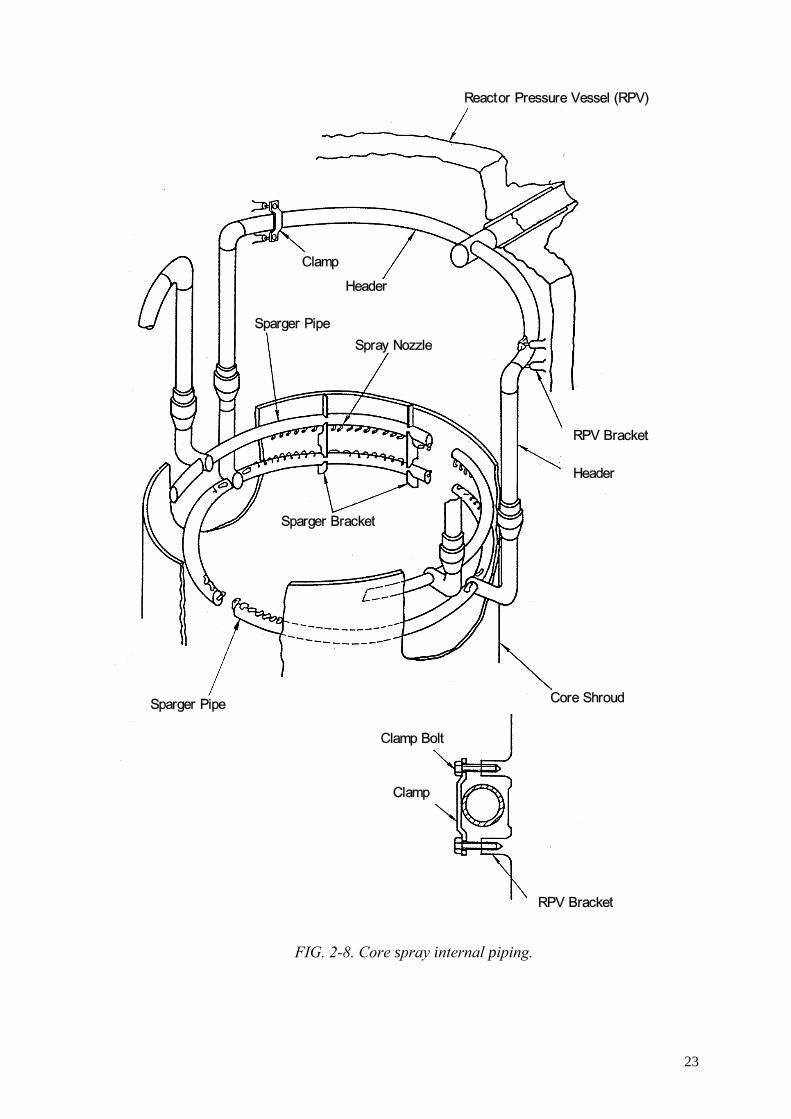
FIG. 2-8. Core spray internal piping.
Reactor Pressure Vessel (RPV)
Clamp
Header
Sparger PipeSpray Nozzle
RPV Bracket
Header
Sparger Bracket
Sparger Pipe Core Shroud
Clamp Bolt
Clamp
RPV Bracket
23
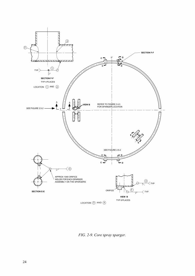
FIG. 2-9. Core spray sparger.
C D
D
C
C
D
D
0°
VIEW B
T
E
E
C
SEE FIGURE 2.5-2
SECTION F-F
A AREFER TO FIGURE 2.4-3FOR SPARGER LOCATION
SEE FIGURE 2.5-2
LOCATION 43 AN D
1
SECTION F-F
TYP 4 PLACES
APPROX 1040 ORIFICEWELDS FOR EACH SPARGERASSEMBLY ON THE SPARGERS
SECTION E-E
3
ORIFICE 3
4
VIEW BTYP 8 PLACES
TYP
TYP
TYP
2
2
21 LOCATION AND
24

FIG. 2-10. Control rod guide tube and fuel support assembly.
Top Guide
Control Rod
Control Plate
Fuel Assembly
Fuel Support
Control Rod Guide Tube
Control Rod Drive Housing
Reactor Pressure Vessel
Stub Tube
25

FIG. 2-11 (a). Typical GE CRD housing.
Stub Tube
Reactor Pressure Vessel
Control Rod Drive Housing
26

FIG. 2-11 (b). Typical ABB CRD housing.
27

FIG. 2-12. In-core housing.
Weld Buildup
RPV
In-Core Housing
28

FIG. 2-13. Jet pump assembly.
Riser Brace
Riser
Wedge
Diffuser Collar
Recirculation Inlet Nozzle
Reactor Pressure Vessel
Diffuser
Adapter
Core Shroud
Core Plate
Inlet Mixer
Inlet Mixer Nozzle
Jet Pump Beam
29

FIG. 2-14. LPCI coupling.
Flange
BellowsCover
Clamp
Pin
Reactor Pressure Vessel Thermal Sleeve
SleeveFlange Ring Flange
Core Shroud
30

FIG. 2-15. Core shroud and core shroud support.
Reactor Pressure Vessel
Upper Ring
Upper Shell
Middle Ring
Middle Shell
Lower Ring
Lower ShellShroud Support Cylinder
Shroud Support PlateShroud Support Leg
H7a
H7b
H6a
H6b
H4
H1
H2
H3
Weldlines
31

FIG. 2-16. Shroud support access hole cover.
Section A-A
Access Hole Cover
L-shape Bolt
Shroud Support Plate
Weld Type
Bolt and Nut Type
SHROUD SUPPORT PLATE ALLOY 600
ACCESS HOLE COVERALLOY 600
.25 in.
1.97 TO 2.50 in. 1.97 TO 2.50 in.
WELDBUILD-UP
32

FIG. 2-17. Top guide.
ABWR
BWR-5
Lowe
r Gui
de
BW
R 6
33
2.2. Materials Various product forms are used in the manufacture of reactor pressure internals.
These various product forms include plates, bar, piping, forgings, rolled rings, and castings of austenitic stainless steel or Ni base alloy. The reactor pressure vessel internals are joined, by either welding, wedging or bolting together, to form a complete assembly. Stainless steels and Ni base alloy have been used in the manufacture of reactor pressure vessel internals because of their corrosion resistance, toughness, ductility, strength and fatigue characteristics in boiling water reactor environment.
In GE type vessel internals, AISI Type 304 and 304L stainless steel are used in various product forms in most of the internals components, as for example, core plate, Jet-pump, core shroud, steam dryer and top guide. Alloy 600 is used in shroud support.
In recent Japanese plants (BWR/5 & ABWR), JIS Type 316L and 316 stainless steel with low carbon (≤0.020%) are mainly used to improve the IGSCC resistance in various product forms in most of the core internals. For nickel base alloy components, modified Alloy 600 in which 1-3% Nb is added, and Nb/C controlled alloy 82 (for weld materials) are used to improve the IGSCC resistance.
RPVIs in Siemens plants are fabricated from Nb-stabilized stainless steel (German material designation 1.4550). In some rare cases other materials have been used for a very small number of components e.g. Nb stabilized molybdenum containing stainless steel (German material designation 1.4571), Ti-stabilized stainless steel (German material designation 1.4541), non stabilized stainless steel 304 L (German material designation 1.4301) as well as Ni base alloy.
The materials used for internals in the ABB Atom BWRs are mainly made of Type 304 or Type 304L materials, but some stabilized steels, such as Type 347, have also been used.
Materials for typical reactor vessel internals and their chemical composition are given in Tables 2-2. to 2-5.
2.3. Classification for importance to safety The classification basis for the “important to safety” categorization of RPVIs consists
of a review of design features, including design function, and component safety function of RPVI systems, structures or components during normal operation and in response to design basis accidents, transients and seismic events. The safety functions considered are those associated with (1) to support the core under all load conditions and maintain coolable geometry, (2) to assure control rod insertion times, (3) to assure reactivity control, (4) to direct and contain core cooling, (5) to assure availability of monitoring instruments and (6) to allow recovery to safe shutdown conditions. Some RPVIs also have a function (7) to maintain reactor coolant pressure boundary. In this report the term “components important to safety” is defined as follows:
• components which have one or more of the above safety functions; • components failure of which results in a loss of the above safety functions.
The results of classification are shown in Table 2-6.
34

TABLE 2-2 TYPICAL RPVI MATERIALS
Standards and specifications Component GE reactors (BWR/6)
(ASME, ASTM) Japanese reactors (METI Not.501, JIS)
Siemens reactors (KTA 3204, 6/98)
ABB reactors (ASME, ASTM?)
Core Plate SA-240 Type 304L JIS G 4304 SUS316 1.4550 304(L) Core Plate dp/SLC line
- JIS G 3459 SUS316LTP 1.4550 304(L)
Core Spray Internal Piping
A/SA-312 and 403 Type 304 or 316L
JIS G 3459 SUS316LTP - 304(L), 316L
Core Spray Sparger A/SA-312 and 403 Type 304
JIS G 3459 SUS316LTP - 304(L), I-600
CRD Guide Tube SA-240, 312, and 351 Type 304 and CF3 *1
JIS G 4304 SUS316L JIS G 3214 SUSF316L
1.4550 304(L)
CRD Housing SA-182 and 312 Type 304 and SB-166 or 167 N06600 *1
JIS G 3214 SUSF316 1.4550 304(L)
Feedwater Sparger A/SA-182, 240,312, Type 304 or 316L, 403, and 351 and CF3
JIS G 3459 SUS316LTP 1.4550 304(L)
In-Core Housing SB-167 N06600 JIS G 3214 SUSF316 1.4550 Internal Recirculation Pump
- JIS G 3214 SUSF6NM 1.4313 for medium touched parts (acc. to KTA 3201.1)
several materials
Jet Pump A/SA-240, 312 and 351 CF8 and 304 or 304L
JIS G 5121 SCS19A JIS G 3459 SUS316LTP JIS G 4304 SUS316L JIS G 3214 SUSF316L JIS G 4901 NCF600
- -
LPCI Coupling - JIS G 3214 SUSF316L JIS G 4304 SUS316L
- 304(L)
Neutron Source Holders
- JIS G 3459 SUS316LTP 1.4550 304(L)
Orificed Fuel Support
SA-351 CF8 or CF3 JIS G 5121 SCS19A 1.4550 304(L)
Core shroud SA-240 Type 304L JIS G 4304 SUS316L 1.4550 304(L), 316 L(NG) Shroud Head SA-240 Type 304L JIS G 4304 SUS316L 1.4550 304(L), 316L(NG) Shroud Support JIS G 4902 NCF600 1.4550 304(L) Steam Dryer SA-240 Type 304 JIS G 4304 SUS316L 1.4550 304(L) Steam Separators SA-213/249/312 Type
304 or 304L JIS G 4304 SUS316L JIS G 3459 SUS316LTP
1.4550 304(L), 316 L
Surveillance Capsule Holder
- JIS G 4304 SUS316L 1.4550 304(L)
Top Guide SA-240 Type 304L JIS G 4304 SUS316L 1.4550 304(L), 316 LNG
*1: Core Support Structure according to ASME, Section III, NG
35

TAB
LE 2
-3 C
HEM
ICA
L C
OM
POSI
TIO
N O
F R
PVI M
ATE
RIA
LS- A
UST
ENIC
STA
ILES
S ST
EELS
Mat
eria
l C
M
n Si
S
P N
i C
r M
o N
b+Ta
Ti
C
o C
u N
O
ther
s Ja
pane
se B
WR
s JI
S G
430
4 SU
S316
L ≤0
.020
≤2
.00
≤1.0
0 ≤0
.03
0 ≤0
.045
12
.00-
15
.00
16.0
0-
18.0
0 2.
00-
3.00
-
- ≤0
.25
- -
-
JIS
G 3
459
SUS3
16LT
P ≤0
.020
≤2
.00
≤1.0
0 ≤0
.03
0 ≤0
.040
12
.00-
16
.00
16.0
0-
18.0
0 2.
00-
3.00
-
- ≤0
.25
- -
-
JIS
G 3
214
SUSF
316L
≤0
.020
≤2
.00
≤1.0
0 ≤0
.03
0 ≤0
.040
12
.00-
15
.00
16.0
0-
18.0
0 2.
00-
3.00
-
- ≤0
.25
- ≤0
.12
-
JIS
G 4
304
SUS3
16
≤0.0
20
≤2.0
0 ≤1
.00
≤0.0
30
≤0.0
45
10.0
0-
14.0
0 16
.00-
18
.00
2.00
-3.
00
- -
≤0.2
5 -
- -
JIS
G 3
214
SUSF
316
≤0.0
20
≤2.0
0 ≤1
.00
≤0.0
30
≤0.0
40
10.0
0-
14.0
0 16
.00-
18
.00
2.00
-3.
00
- -
≤0.2
5 -
≤0.1
2 -
JIS
G 5
121
SCS1
9A
≤0.0
20
≤2.0
0 ≤1
.50
≤0.0
40
≤0.0
40
8.00
- 12
.00
17.0
0-21
.00
- -
- ≤0
.25
- -
-
Siem
ens B
WR
s K
TA 3
204
1.45
50
≤0.0
4 ≤2
.00
≤1.0
0 ≤0
.01
5 ≤0
.035
9.
00-
12.0
0 17
.00-
19.0
0 -
Nb≤
0.65
N
b/C
≥13
- ≤0
.2
- m
ust b
e de
term
ine
d
-
KTA
320
1.1
1.43
13
(Hea
t A
naly
sis)
≤0.0
5 ≤2
.00
≤0.6
0 ≤0
.01
5 ≤0
.030
3.
50-
4.50
12
.60-
13.9
0 0.
30-
0.70
-
- ≤0
.2
- ≥0
.020
-
TAB
LE 2
-4 C
HEM
ICA
L C
OM
POSI
TIO
N O
F R
PVI M
ATE
RIA
LS- W
ELD
S
Mat
eria
l C
M
n Si
S
P N
i C
r M
o N
b Ti
C
o C
u O
ther
s Si
emen
s BW
Rs
KTA
320
4 1.
4550
*)
≤0.0
4 ≤2
.00
≤1.0
0 ≤0
.01
5 ≤0
.03
5 9.
00-
12.0
0 17
.00-
19.0
0 -
Nb≤
0.65
N
b/C
≥13
- ≤0
.2
- m
ust b
e de
term
ined
*) A
ccor
ding
to K
TA 3
204,
for w
elds
, the
sam
e re
quire
men
ts a
pply
as f
or th
e ba
se m
ater
ial.
36

TAB
LE 2
-5 C
HEM
ICA
L C
OM
POSI
TIO
N O
F R
PVI M
ATE
RIA
LS- N
i BA
SE A
LLO
YS
Mat
eria
l C
M
n Si
S
P N
i C
r Fe
N
b(+T
a)
Ti
Co
Cu
Al
Japa
nese
BW
Rs
JIS
G 4
901
NC
F600
≤0
.15
≤1.0
0 ≤0
.50
≤0.0
15
≤0.0
30
≥72.
0 14
.0-
17.0
6.
0-10
.0
1.0-
3.0
-
- -
-
JIS
G 4
902
NC
F600
≤0
.15
≤1.0
0 ≤0
.50
≤0.0
15
≤0.0
30
≥72.
0 14
.0-
17.0
6.
0-10
.0
1.0-
3.0
-
≤0.5
0 -
-
Allo
y182
(wel
ds)
≤0.1
0
≥5
9.0
13.0
-17
.0
≤10.
0 0.
5-3.
0
Allo
y182
m
odifi
ed (w
elds
) ≤0
.10
≥59.
0 13
.0-
17.0
≤1
0.0
2.5-
4.5
Allo
y82
(wel
ds)
≤0.1
0
≥6
7.0
18.0
- 22
.0
≤3.0
2.
0-3.
0
Siem
ens B
WR
s K
TA 3
204
2.
4816
≤0
.08
≤1.0
0 ≤0
.50
≤0.0
15
≤0.0
15
≥72.
0 14
.0-
17.0
6.
0-10
.0
- -
≤0.2
≤0
.5
-
37

TAB
LE 2
-6 C
LASS
IFIC
ATI
ON
FO
R IM
POR
TAN
CE
TO S
AFE
TY
Safe
ty F
unct
ions
C
ompo
nent
(1
) (2
) (3
) (4
) (5
) (6
) (7
) C
lass
ifica
tion
resu
lt
Cor
e Pl
ate
√
√
Im
porta
nt to
safe
ty
Cor
e Pl
ate
∆p/S
LC li
ne
Not
e 1
Not
e 2
N
ot c
onsi
dere
d to
be
impo
rtant
to sa
fety
Cor
e Sp
ray
Inte
rnal
Pip
ing
√
Im
porta
nt to
safe
ty
Cor
e Sp
ray
Spar
ger
√
Im
porta
nt to
safe
ty
Cle
anup
(R
WC
U)
Ret
urn
Spar
ger
N
ot c
onsi
dere
d to
be
impo
rtant
to sa
fety
CR
D G
uide
Tub
e √
√
Impo
rtant
to sa
fety
C
RD
Hou
sing
√
√
√
Impo
rtant
to sa
fety
Fe
edw
ater
Spa
rger
Not
con
side
red
to b
e im
porta
nt to
safe
ty
In-C
ore
Hou
sing
√
√
Impo
rtant
to sa
fety
In
tern
al R
ecirc
ulat
ion
Pum
p
Not
con
side
red
to b
e im
porta
nt to
safe
ty
Jet P
ump
N
ote
4
√
Impo
rtant
to sa
fety
LPC
I Cou
plin
g
√
Impo
rtant
to sa
fety
N
eutro
n So
urce
Hol
ders
Not
con
side
red
to b
e im
porta
nt to
safe
ty
Ther
mal
Shi
eld
N
ot c
onsi
dere
d to
be
impo
rtant
to sa
fety
O
rific
ed F
uel S
uppo
rt √
√
Impo
rtant
to sa
fety
C
ore
shro
ud
√ √
√
√
Im
porta
nt to
safe
ty
Shro
ud H
ead
Fo
r som
e pl
ants
impo
rtant
to sa
fety
Not
e 3
Shro
ud S
uppo
rt √
√
√
Impo
rtant
to sa
fety
St
eam
Dry
er
N
ot c
onsi
dere
d to
be
impo
rtant
to sa
fety
St
eam
Sep
arat
ors
N
ot c
onsi
dere
d to
be
impo
rtant
to sa
fety
Su
rvei
llanc
e C
apsu
le H
olde
r
Not
con
side
red
to b
e im
porta
nt to
safe
ty
Top
Gui
de
√ √
Im
porta
nt to
safe
ty
Safe
ty fu
nctio
n (1
): to
supp
ort t
he c
ore
unde
r all
load
con
ditio
ns a
nd m
aint
ain
cool
able
geo
met
ry
Safe
ty fu
nctio
n (2
): to
ass
ure
cont
rol r
od in
serti
on ti
mes
Sa
fety
func
tion
(3):
to a
ssur
e re
activ
ity c
ontro
l Sa
fety
func
tion
(4):
to d
irect
and
con
tain
cor
e co
olin
g Sa
fety
func
tion
(5):
to a
ssur
e av
aila
bilit
y of
mon
itorin
g in
stru
men
ts
Safe
ty fu
nctio
n (6
): to
allo
w re
cove
ry to
safe
shut
dow
n co
nditi
ons
Safe
ty fu
nctio
n (7
): to
mai
ntai
n re
acto
r coo
lant
pre
ssur
e bo
unda
ry
38

Not
es:
*1
Th
e fa
ilure
of
the
SLC
pip
e w
elds
of
the
inne
r pi
ping
of
the
sens
ing
line
from
the
RPV
pen
etra
tion
to th
e dP
/SLC
line
tee
can
resu
lt in
a
redi
strib
utio
n of
som
e po
rtion
of t
he s
odiu
m p
enta
bora
te fr
om th
e lo
wer
ple
num
are
a to
the
area
imm
edia
tely
abo
ve th
e co
re p
late
via
the
sens
ing
line.
Si
nce
any
solu
tion
disc
harg
ed a
bove
the
core
pla
te is
stil
l dis
tribu
ted
thro
ugh
the
core
, shu
tdow
n w
ill b
e ac
hiev
ed. T
hus
bypa
ss le
akag
e th
roug
h a
degr
aded
SLC
pip
e w
eld
wou
ld n
ot h
ave
an a
dver
se im
pact
on
achi
evin
g sa
fe sh
utdo
wn
of th
e re
acto
r.
*2
Failu
re o
f ∆p
/SLC
pip
e w
elds
cou
ld r
esul
t in
los
s of
the
cor
e pl
ate
diff
eren
tial
pres
sure
mea
sure
men
t an
d w
ould
cau
se t
he m
onito
ring
inst
rum
enta
tion
to in
dica
te lo
wer
than
nor
mal
or n
o co
re p
late
diff
eren
tial p
ress
ure
durin
g no
rmal
ope
ratio
n. H
owev
er, t
his
is n
ot a
saf
ety-
sign
ifica
nt i
ssue
and
nor
mal
mon
itorin
g of
the
cor
e pl
ate
diff
eren
tial
pres
sure
or
the
CR
D s
yste
m d
iffer
entia
l pr
essu
re w
ill p
rovi
de a
n in
dica
tion
of p
oten
tial S
LC/d
P lin
e de
grad
atio
n.
*3
The
shr
oud
head
is im
porta
nt to
saf
ety
for
all t
ypes
of
AB
B A
tom
BW
Rs
sinc
e th
e co
re s
pray
is c
lam
ped
betw
een
the
core
grid
and
the
shro
ud h
ead.
*4.
For p
lant
s tha
t inj
ect L
PCI t
hrou
gh th
e je
t pum
p, S
afet
y Fu
nctio
n 4
appl
ies.
39

3. DESIGN BASIS, CODES, STANDARDS AND REGULATIONS
3.1. Requirements in the USA Part 50 of the Code of Federal Regulations, Title 10 (10CFR50) [3.1] regulates
construction of nuclear power plants. More specifically, 10CFR50.55a cites Section III of the ASME Code [3.2] which is the industry standard for construction of nuclear power plant facilities, and Section XI of the ASME Boiler and Pressure Vessel Code [3.3] which prescribes in-service inspection requirements, including inspection and evaluation of defects.
Reactor internals design fabrication and installation are covered by rules given in Section III of the ASME Boiler and Pressure Vessel Code, Subsection NG, Core Support Structures. Core support structures are those structures or parts of structures, which are designed to provide direct support or restraint of the core, within the reactor pressure vessel. Before Subsection NG was published, Subsection NB of the ASME Code was used as a guideline for the development of vendor-specific internals system design criteria. The rules for reactor internals design are covered in Article NG-3000.
The rules for reactor internals materials are covered in Article NG-2000. The majority of reactor internals are fabricated using austenitic stainless, both wrought and castings and nickel base alloys (Alloy X-750, Alloy 600, etc.). Fabrication and installation of reactor internals are covered in Article 4000. Pre-service inspection is addressed in both Articles NG-2000 and NG-4000.
Although a large number of BWR reactor pressure vessel internals were designed and fabricated prior to the publication of Subsection NG, the design philosophies of the NSSS vendors throughout the western world were such that the intent of Subsection NG was met. In the USA in addition to the requirements of the ASME Code, Section III, Subsection NG, a limited number of regulatory guides and bulletins are relevant to reactor vessel internals components assessment and management of ageing.
ASME Boiler and Pressure Vessel Code Section III, Subsection NG
ASME Section III, Subsection NG, Boiler and Pressure Vessel Code, Article NG-3000, which is divided into three subsections covers the design of reactor vessel internals. The three subsections of Article NG-3000 are:
• NG-3100 General Design • NG-3200 Design by Analysis • NG-3300 Core Support Structural Design.
Subarticle NG-3100 deals with Loading Conditions specified by the Owner (or his agent) in the form of an Equipment Specification. The equipment specification identifies the Design Loading in terms of Design Pressure Difference, Design Temperature, Design Mechanical Loads and Design Stress Intensity Values. The Equipment Specification identifies the Design and Operating Conditions.
Subarticle NG-3200 deals with the stresses and stress limits which must be considered for the analysis of the component. The reactor vessel internals are designed to withstand steady state and fluctuating loads produced under handling, normal operating
40

transient and accident conditions. The equipment specification identifies the operating conditions. In the 1974 Edition of Subsection NG, there are four categories entitled:
• Normal Conditions • Upset Conditions • Emergency Conditions and • Faulted Conditions.
Later code editions clarified this nomenclature but basically retained the same stress allowables. The corresponding new categories are:
• Service Level A • Service Level B • Service Level C • Service Level D.
Subarticle NG-3300 gives the general design requirements for core support structures. The design of Core support structures must meet the requirements of NG-3100 and NG-3200. However, if there is a conflict between NG-3200 and NG-3300, the requirements of NG-3300 shall govern.
System hot functional test
Reactor pressure vessel internals are required to undergo pre-operation testing under hot conditions. Nuclear Regulatory Guide 1.20 establishes guidelines for the pre-operation assessment programme. Reg Guide 1.20 requires an instrumented FIV test of prototype plants and new features. The system hot functional test is done at the plant site and follows the primary system hydrostatic test. The reactor pressure vessel internals are installed in the reactor vessel without fuel. The coolant temperatures are established by pump heating.
Hot functional tests are conducted only once during the plant life. The hot functional test is conducted at elevated temperature and at a flow rate, which is greater than during normal plant operation to assure covering the range of operating flows with margin. The hot functional tests consist of operation with all pumps for a minimum of ten days. The hot functional tests ensures that the flow-induced load cycling (vibration) of the reactor pressure vessel internals will be well into the high cycle range of their material fatigue design curves, thus providing assurance that the high cycle fatigue usage of the reactor pressure vessel internals will be low throughout the plant design life. Upon completion of the hot functional test, a visual inspection is performed.
3.2. Requirements in Germany In Germany, the appropriate standards for RPVIs are at present the safety standards of
the Nuclear Safety Standards Commission, specifically the KTA-3204 [3.4]. The latest issue is from June 1998. This standard shall be applied to the RPVIs of light water reactors as well as to the tools and equipment, used for the installation and removal of the components.
During the design and manufacturing of RPVIs for plants built before 1984 these rules were covered by specifications related to the project.
Components of the RVIs in these standards are categorized in three requirement levels, AS-RE 1 to AS-RE 3, depending on their individual tasks and functions.
41

One chapter deals with the design (construction) and one with the rules for the stress analysis for the RPVIs, which are primary derived from the ASME code. The rules for the RPVIs materials and material testing are covered in another chapter. The requirements for the materials are fixed in special material sheets in the annex. Further chapters contain requirements for the manufacturing and the operational surveillance and testing.
In all the chapters of these standards, the actual German standards and regulations, as e.g. DIN-EN, AD, SEW, VdTüv guidelines, are to be applied.
3.3. Requirements in Japan In Japan, the structural analysis for RPVIs is described in METI notification 501,
[3.5] and JSME Code on Code for Design and Construction for Nuclear Power Plants, JSME S NC1-2001 [3.6], which are based on ASME Boiler and Pressure Vessel Code, Section III..
3.4. Requirements in Finland In Finland nuclear power plant requirements are presented in Nuclear Energy Act,
Nuclear Energy Decree, Decisions of the Council of State and Regulatory Guides given by Radiation and Safety Authority, STUK. Design and analysis requirements are in accordance with ASME III.
Identical ABB-type NPP units, Olkiluoto 1 and 2, were taken into operation on 1978 and 1980. In both units the power is upgraded from original 660 to 840 MWe. The licensing of upgrading included the updating of safety analysis of systems including RPVIs in accordance with current code requirements.
3.5. Requirements in Switzerland In Switzerland there are two BWR units. One plant, a GE BWR-4 type, was taken
into operation in 1971, the other, a GE BWR-6 type plant, is operating since 1984. Regulatory guidelines are provided by the HSK, the Swiss Federal Nuclear Inspectorate. Generally, requirements for design and analysis are in accordance with ASME III. Requirements for inspection are defined in the NE-14 regulation provided by the SVTI, the Swiss Association for Technical Inspections.
REFERENCES IN SECTION 3 [3.1.] OFFICE OF THE FEDERAL REGISTER, Code of Federal Regulations (Energy) 10
Part 50, Domestic Licensing of Production and Utilization Facilities: 50:50 Issuance of Licenses and Construction Permits, Washington (1999).
[3.2.] AMERICAN SOCIETY OF MECHANICAL ENGINEERS, ASME Boiler and Pressure Vessel Code, Section III, “Nuclear Power Plant Components”, ASME, New York (1998).
[3.3.] AMERICAN SOCIETY OF MECHANICAL ENGINEERS, ASME Boiler and Pressure Vessel Code, Section XI, Division 1, “Rules for Inservice Inspection of Nuclear Power Plant Components”, 1998 Edition 2000Addenda, ASME, New York.
[3.4.] NUCLEAR SAFETY STANDARDS COMMISSION, Safety Standards, KTA 3204 Reactor Pressure Vessel Internals, KTA, Cologne (6/1998).
[3.5.] Notification of Establishing Technical Standards on Structures etc., of Nuclear Power Generation Facilities, Ministry of Economy and Industry Notification No. 501, Japan, October 1980.
[3.6.] Japanese Society of Mechanical Engineers, JSME Codes for Nuclear Power Generation Facilities, S NC1-2001, Rules on Design and Construction for Nuclear Power Plant, August 2001, JSME Tokyo.
42

4. OPERATING CONDITONS
This section discusses the operating conditions for RPVIs. The operating conditions determine the presence of specific ageing mechanisms and the rate of potential degradation. 4.1. Neutron exposure and electrochemical corrosion potential
Information available concerning approximate neutron fluence and electrochemical potential for the representative components of GE, Japanese, Siemens and ABB BWR plants is shown in Table 4-1.
TABLE 4-1 OPERATING CONDITIONS FOR BWR RPVIs
Fluence
Plant component E>0.1 MeV (n/m2)
E> 1 MeV (n/m2)
Electro-chemical corrosion potential (Normal Water Chemistry) [mV (SHE)]
GE BWR/3
Core Plate - 2.0 x1024
Core shroud - 2.7 x1024
Top Guide - 4.0 x1024
[NWC]3) Lower plenum: >150 Core plate: not measured [HWC]3) 4) Lower plenum: <-400 Core plate: < -300
GE BWR/6 Core Plate - 1.7 x1024 Core shroud - 1.0 x1025 Top Guide - 1.1 x1025
-
Japanese BWR/41)
Core Plate (top) 3.6 x1024 2.1 x1024
Core shroud (H4) 1.3 x1025 7.4 x1024
Top Guide (bottom) 1.6 x1026 7.2 x1025
[NWC] 5) Upper Core: about 80 Lower Core: about 120 [HWC] 4) 5) Upper Core: about -90 Lower Core: about -180
Japanese BWR/51) Core Plate (top) 5.9x1024 3.2 x1024 Core shroud (H4) 1.9 x1025 1.0 x1025 Top Guide (bottom) 1.1 x1026 5.4 x1025
-
Siemens Reactors (Type 721)) Core Plate - <2 x1025 Core shroud - <3 x1025 Top Guide - <1 x1026
[NWC] 6)
about 150
ABB Reactor (Finnish Reactor) 2) Core Plate - - Core shroud - 2.2 x1025 Top Guide - -
-
ABWR1) Core Plate (top) 3.3 x1024 1.7 x1024 Core shroud (H4) 1.9 x1025 1.0 x1025 Top Guide (bottom) 2.0 x1025 1.1 x1025
-
1) Fluence values are those after 32EFPY. 2) Fluence value is one after 40 years. 3) Measured at Santa Maria De Garona NPP in Spain 4) Hydrogen Concentration at Feed Water is 1 ppm. 5) Measured at Fukushima Dai-ichi NPP No.3 Unit [4.1] 6) Measured at the cleanup line pipe near the RPV (about 1 m) in Gundremmingen NPP Unit B [4.2]
43

4.2. Primary coolant chemistry specification The important parameters of the BWR primary coolant chemistry are conductivity,
pH level, dissolved oxygen, sulfate and chloride. The BWR coolant is a high purity electrolyte. Therefore, conductivity is very low.
The EPRI guidelines for BWR primary coolant system water chemistry [4.3] is listed in Table 4-2a for Normal Water Chemistry (NWC) and Table 4-2b for HWC (Hydrogen Water Chemistry) or HWC+NMCA (Noble Metal Chemical Addition). The NWC guideline is also followed in Finland.
For German BWRs, the VGB Guideline for the Water in Nuclear Power Plants with Light Water Reactors specifies the qualitative feedwater and reactor water requirements. This guideline was revised in 1996. Table 4-3a to c show the operating values of the revised VGB Guideline. Experience of corrosion cracking in steels 1.4541 (pipe work) and 1.4550 (core shroud region) and the EPRI Guideline were taken into account for this revision. However there are some discrepancies between this guideline and the EPRI Guideline. For example, the VGB Guideline does not specify HWC or HWC + NMCA operational conditions (and the related ECP estimation) due to the differently structured materials concept, i.e. use of stabilized stainless steels.
44
TABLE 4-2a EPRI WATER CHEMISTRY GUIDELINES REACTOR WATER –NWC- POWER OPERATION (>10% Power) a
Note: This table applies to site specific target components exposed to NWC environments or not protected to –230 mV(SHE) by HWC.
Frequency Action Levels [4.3]
Control Parameter of Measurement 1 2 3
Conductivity (µS/cm) Continuously >0.30 >1.0 >5.0
Chloride (ppb) Daily b >5 >20 >100
Sulfate (ppb) Daily b >5 >20 >100
Zinc (ppb) c ---
Diagnostic Parameter Frequency of Measurement Comments
Oxygen (ppb) Continuously
Silica (ppb) --- ---
60Co, 65Zn (Zinc plants only) d Weekly Sample b ---
Iron (ppb) Monthly (e)
Notes:
(a) If HWC is not incorporated into the station chemistry program, an engineering evaluation should be performed to support the decision using an appropriate assessment methodology.
(b) These frequencies can be adjusted based on site-specific resource allocation needs. Recognizing that chloride and sulfate have associated near-term operational actions for off-normal conditions, relaxation of the frequencies should only be performed when conductivity values and/or chemistry trends could be used to ensure that the Action Level 1 limits are not exceeded.
(c) Consistent with utility program for zinc injection
(d) To help evaluate shutdown radiation field reduction program. Consideration should be given also to 58Co and 54Mn species. Soluble and insoluble fractions should be determined.
(e) Basis for iron mass balance.
45
TABLE 4-2b EPRI WATER CHEMISTRY GUIDELINES REACTOR WATER –HWC or HWC+NMCA- POWER OPERATION (>10% Power) a
NOTE: This table is applicable to power operation of BWR reactor water when components are protected to –230 mV (SHE) by HWC or HWC + NMCA. For all components that are provided less protection, plant-specific evaluations should be performed to ensure the values presented in this table are acceptable.
Frequency Action Levels [4.3]
Control Parameter of Measurement 1 2 3
Local ECP a (mV, SHE) ---
Conductivity (µS/cm) Continuously >0.30 g >1.0 >5.0 b
Chloride (ppb) Daily c >5 >50 >200 b
Sulfate (ppb) Daily c >5 >50 >200 b
Zinc (ppb) d ---
Diagnostic Parameter Frequency of Measurement Comments
Oxygen (ppb) Continuously (e)
Silica (ppb) --- --- 60Co, 65Zn (Zinc plants only) f Weekly Sample c ---
Iron (ppb) Monthly (h)
Notes:
(a) Section 5 of [4.3] identifies alternate methods (e.g., main steam line radiation fields) for estimating ECP. (b) If elevated concentrations are not covered by an existing analysis, a plant specific analysis must be
conducted within 4 hours to determine whether plant shutdown or cooldown is the most prudent approach to take with regard to IGSCC and fuel damage.
(c) These frequencies can be adjusted based on site-specific resource allocation needs. Recognizing that chloride and sulfate have associated near-term operational actions for off-normal conditions, relaxation of the frequencies should only be performed when conductivity values and/or chemistry trends could be used to ensure that the Action Level 1 limits are not exceeded.
(d) Consistent with utility program for zinc injection (e) Plant-specific value during hydrogen addition. (f) To help evaluate shutdown radiation field reduction program. Consideration should be given also to 58Co
and 54Mn species. Soluble and insoluble fractions should be determined. (g) For plants starting up with NMCA, contributions due to soluble iron may be subtracted from the measured
conductivity to evaluate conformance to action levels. (h) Basis for iron mass balance. Soluble iron could contribute to conductivity at NMCA plants.
46

TABLE 4-3a VGB GUIDELINE FOR THE WATER IN NUCLEAR POWER PLANTS WITH LIGHT WATER REACTORS: OPERATING VALUES FOR REACTOR FEED WATER AND REACTOR WATER OF BOILING WATER REACTORS IN CONTINUOUS OPERATION.
Normal Action Levels
operating value Level 1 Level 2 Level 3
Reactor feedwater
Conductivity at 25°C direct and continuous measurement at the sampling point (µS/cm)
• 0.061 > 0.071 --- ---
Total ion (µg/kg) • 22 > 5 --- ---
Total copper (µg/kg) • 0.33
> 0.75 --- ---
Oxygen (µg/kg) 20-200 < 20 and > 200
--- ---
Reactor water
Conductivity at 25°C direct and continuous measurement at the sampling point (µS/cm)
• 0.15 > 0.25 > 1 > 5
Chloride (µg/kg) • 10 > 20 > 100 > 200
Sulphate (µg/kg) • 10 > 20 > 100 > 200
Silica (µg/kg) • 200 --- --- --- (1) These are requirements which — in individual cases — cannot be recorded by measuring technology,
although they describe the general state of feedwater. (2) Depending on arrangement, cleaning process and material concept of the plant, different concentration of the
total iron content between 0.2 to 0.5 µg/kg can occur an can be tolerated. (3) Depending on condenser tubing, different concentrations between 0.2 to 0.5 µg/kg can occur and can be
tolerated.
Conductivity is to be measured continuously, chloride and sulphate are to be measured twice a week, and in case the specified value amounts to 1, it is to be measured daily or more frequently until the reason has been found. Silica is to be considered as “diagnostic parameter”.
47

TABLE 4-3b VGB GUIDELINE FOR THE WATER IN NUCLEAR POWER PLANTS WITH LIGHT WATER REACTORS DEFINITION OF SPECIFIED VALUE 1 (ACTION LEVEL 1), SPECIFIED VALUE 2 (ACTION LEVEL 2) AND LIMITING VALUE (ACTION LEVEL 3)
If the water quality deteriorates, measures have to be taken to remove the cause. If the values indicated in Table 4-3a are exceeded, the following procedure is recommended.
Action level 1/ specified value 1:
According to technical instructions, the causes for the poor water quality have to be determined and removed within adequate time. The results have to be documented.
Action level 2/ specified value 2:
If plant personnel do not succeed to improve the water quality within 36 hours so that the specified value 2 is undercut, the plant has to be shut down normally and carefully. If it is foreseeable that the specified value 2 will be undercut within the period necessary for achieving <100°C in the pressure vessel, the plant can be further operated.
Action level 3/ limiting value:
If the limiting value is exceeded, the plant has to be shut down normally and carefully after 12 hours (period to verify the parameter causing the trouble). If it is foreseeable that the specified value 2 will be undercut within the period necessary for achieving <100°C in the pressure vessel, the plant can be further operated.
TABLE 4-3c VGB GUIDELINE FOR THE WATER IN NUCLEAR POWER PLANTS WITH LIGHT WATER REACTORS OPERATING VALUES FOR REACTOR FEED WATER OF BOILING WATER REACTORS AT TEMPERATURES <100°C.
Normal Action Levels
operating value Level 1 Level 2 Level 3
Reactor feedwater
Conductivity at 25°C, direct and continuous measurement at the sampling point (µS/cm)
~ 1 > 2 --- ---
Chloride (µg/kg) • 20 > 50 --- ---
Sulphate (µg/kg) • 20 > 50 --- ---
Conductivity is to be measured continuously, chloride and sulphate are to be measured twice a week, and in case the specified value amounts to 1, it is to be measured daily or more frequently until the reason has been found.
48

REFERENCES TO SECTION 4
[4.1.] K. Takamori et al., The Experience and Future Plan of HC of TEPCO BWRs,
Seminar on water chemistry of Nuclear Reactor Systems, 1995 Tokyo Japan. [4.2.] J. Haag et al., Corrosion and Redox Potential Measurements in German Pressurized
and Boiling Water Reactors, Eighth International Symposium on Environmental Degradation of Materials in Nuclear Power Systems — Water Reactors, 1997 Florida USA.
[4.3.] “BWR Water Chemistry Guidelines – 2000 Revision,” BWRVIP-79, EPRI Report TR-103515-R2, February 2000.
49
5. AGEING MECHANISIMS
This section describes the ageing mechanisms that can affect BWR RPVIs and evaluates the potential significance of the effects of these mechanisms on the continued performance of safety functions of the RPVIs throughout the plant service life.
Ageing mechanisms are specific processes that gradually change characteristics of a component with time and use. Ageing degradation are those cumulative changes that can impair the ability of a component to function within acceptance criteria. Service conditions outside prescribed limits can accelerate the rate of degradation.
Evaluation of age related degradation mechanisms is based on BWR service experience, pertinent laboratory data, and relevant experience from other industries. The following mechanisms will be reviewed and assessed for relevance to RPVIs:
• embrittlement • fatigue • stress corrosion cracking • general corrosion • erosion/corrosion • mechanical wear
5.1. Embrittlement There are two types of embrittlement, which could affect BWR vessel and internal
components. These are (1) radiation embrittlement, which may affect core region internals, and (2) thermal embrittlement, which may affect the cast stainless steel fuel supports.
5.1.1. Description of radiation embrittlement Neutrons produce energetic primary recoil atoms, which displace large numbers of
atoms from their crystal lattice positions by a chain of atomic collisions. The number of neutrons bombarding a given location is traditionally measured by the fluence (n/m
2 with
E>1.0 MeV). A more recent neutron damage exposure measure is displacements per atom (dpa), which accounts for a wider neutron energy spectrum than the fluence. The fluence or dpa provide part of the information needed to assess radiation embrittlement.
The actual mechanism of radiation embrittlement is not completely understood. For example, in low alloy RPV steel, radiation embrittlement is a function of both environmental and metallurgical variables. Fluence or dpa, and copper and nickel content have been identified as the primary contributors in US NRC Regulatory Guide 1.99, Revision 2 [5.1]. Other important variables include flux, temperature and phosphorus content. There is evidence that other variables such as heat treatment may also influence embrittlement. Therefore, mathematically based statistical data correlation are subject to uncertainty.
Wrought austenitic stainless steels do not exhibit the sharp ductile to brittle transition behavior characteristic of low alloy and carbon steels. Rather, toughness losses due to irradiation tend to accumulate with increasing fluence and saturate at levels >1 x 1025 n/m2. Until recently, there was little information available to quantify the effects of radiation embrittlement on RPVIs. New information [5.2] describes the results of a fracture toughness study performed on irradiated Type 304 stainless steel reactor internal material taken from
50

operating BWRs with fluences ranging from 1 x 1025 to 6 x 1025 n/m2, (E>1 MeV). This study confirmed a fracture toughness saturation level of 55 MPa√m for all fluences considered and can be directly applied to the evaluation of highly irradiated RPVIs.
Thus, there appears to be no life limiting degradation due to radiation embrittlement alone. Although resistance to crack propagation in internals materials decreases with increasing neutron fluence fracture toughness remains high, degradation of stainless steel RPVIs can effectively be assessed using fracture mechanics analyses.
5.1.2. Description of thermal ageing embrittlement Thermal ageing embrittlement is a time and temperature dependent degradation
mechanism. It is caused by the thermally activated movement of lattice atoms over a long time period, a process which can occur without external mechanical load. Changes in microstructure and material properties (e.g., embrittlement, as indicated by a decrease in ductility and toughness and an increase in strength properties and hardness) are the consequence of these diffusion processes. The significant parameters responsible for these ageing processes are:
• temperature; • material state (microstructure); • time.
Susceptible to this kind of mechanisms are cast stainless steels, to a lesser extent weld metal and some Cr rich martensitic steels. Several research projects funded by the USNRC, EPRI, George Fisher Limited of Switzerland, and a consortium of Westinghouse, Framatome and EDF have evaluated mechanical property degradation which results from thermal ageing embrittlement in typical cast duplex stainless steel materials [5.3].
Thermal aging causes a change in microstructure which results in embrittlement. Thermal ageing embrittlement of cast stainless can lead to precipitation of additional phases in the ferrite, e.g., formation of Cr-rich α–prime, phase by spinoidal decomposition; nucleation and growth of α -prime; precipitation of a Ni- and Si-rich phase, M23 C6 carbides and growth of existing carbides at the ferrite/austenitic phase boundaries. Cast duplex stainless steel used in the PWR primary piping can be susceptible to thermal ageing embrittlement at PWR operation temperature, i.e., 290 – 325 º C. Thermal ageing embrittlement of cast duplex stainless steel at these temperatures can cause an increase in the hardness and tensile strength and a decrease in ductility, impact strength and fracture toughness of the material.
Cast stainless steel is a duplex structure consisting of austenite and ferrite. Precipitates form in the ferrite phase or at the grain boundaries at certain temperature ranges. Such precipitates are known to form at temperatures as low as 450°C, but there is concern that precipitation may occur at temperatures as low as 250°C over long periods of time. Such precipitation would cause reduction in toughness. [5.4]
5.1.3. Significance of embrittlement Embrittlement, either due to irradiation or thermal effects, does not directly cause
cracking. However, the margin of a material to resist propagation of cracks due to other causes such as fabrication, fatigue or SCC is reduced. The significance of embrittlement for a given component depends on the probability of cracking, and the loading of the component.
51
While neutron irradiation results in some reduction in fracture toughness at the center of the top guide and the midplane of the core shroud, fracture toughness remains high. Further consideration of irradiation embrittlement of RPVIs is not required. However, for cracked components, a fracture mechanics evaluation of material that has been exposed to high neutron fluence should be performed to assure crack stability on a component specific basis.
Thermal ageing is not a significant degradation mechanism for RPVIs made from wrought steel or Ni-Cr-Fe because the specific materials used in the BWR application are not susceptible to the mechanism. Thermal ageing is not a significant degradation mechanism for the orificed fuel supports which are made from cast stainless steel because stress levels are so low [~15 MPa (<2 ksi) with no residual stress]. These stress levels are not of sufficient magnitude to cause cracking of the orificed fuel support irrespective of the delta ferrite content. Therefore, thermal ageing is not a significant degradation mechanism for any RPVIs.
5.2. Fatigue
5.2.1. Description Fatigue is defined as the structural deterioration that occurs as a result of repeated
stress/strain cycles caused by fluctuating loads and temperatures. After repeated cyclic loading of sufficient magnitude micro-structural damage can accumulate, leading to macroscopic crack initiation at the most highly affected locations. Subsequent continued cyclic loading can lead to the growth of the initiated crack.
Fatigue behavior is related to a variety of parameters, such as stress range, mean stress, cycling frequency, surface roughness and environmental conditions. Cracks initiate at stress concentrations such as geometric notches and surface defects. Fatigue initiation curves indicate how many stress cycles it takes to initiate fatigue cracks in components. These curves are materials related and indicate the allowable number of stress cycles for applied cyclic stress amplitudes. Design curves for RPV materials are given in ASME Section III, Appendix I or respective national standards such as KTA 3204 or METI notification 501.
Environment can significantly influence fatigue crack initiation. Environmentally assisted fatigue, often referred to as corrosion fatigue, must be considered when dealing with components in the BWR environment.
There are three sources of fatigue significant to the BWR. These are system cycling, thermal cycling and flow induced vibration.
System cycling
System cycling refers to changes in the reactor system operating conditions which cause variations in pressure and temperature. Examples of system cycling are startups, shutdown, SCRAM and safety/relief valve (SRV) actuation. Some system cycling events only affect a portion of the vessel. For example, loss of feedwater heaters is significant to the feedwater nozzle and sparger, but has no noticeable impact elsewhere in the vessel. System cycling was the best understood source of fatigue during the time of vessel design.
Many vessel components were designed against system cycling fatigue crack initiation, using conservative amplitudes and frequencies of normal and upset loading cycles, together with the fatigue design curves of the ASME Code, Section III, Appendix I. Although the design process for internals considered system cycling fatigue in a less
52

formalized manner, operating experience to date demonstrates that consideration of system cycling in the internals design process was adequate. The few documented cases of RPVI fatigue failures have been attributed to other fatigue sources.
Thermal cycling
Fatigue thermal cycling may occur due to temperature fluctuations. Temperature transients during operation can cause local or global temperature gradients, resulting in thermal cycling at the interface of material and environment. Smooth and sharp temperature transients result in slow or rapid thermal cycling, both of which are a source of fatigue usage. Causes for smooth transients are generally start up and shutdown procedures or load following operation modes. Connections and disconnection of systems, ECCS water injection, and leaking of hot or cold water through untight valves may result in rapid thermal cycling. The effect of both is ageing of material in terms of low cycle fatigue (slow cycling), or high cycle fatigue (rapid cycling).
Fatigue thermal cracking due to rapid cycling has been discovered in several plants. For example, at Oskarshamn 1 the core shroud, shroud support and feed water skirt have experienced thermal fatigue cracks.
Feedwater spargers also experienced fatigue cracking due to both thermal cycling and FIV. In the 1970’s two types of problems were found with the feedwater spargers, the first was failure due to high vibration and the second was cracking of feedwater nozzles due to thermal cycling. An extensive development program resulted in improved designs, which are used in most plants today. NUREG 0619 [5.5] documents the USNRC evaluation of this problem and its requirements of surveillance.
Flow induced vibration
Flow induced vibration (FIV) fatigue has been observed in several RPVIs, e.g., jetpumps and steam dryers. FIV is caused when coolant flowing past a component sheds vortices, which create cyclic loads. These loads generally occur in a frequency range up to about 20 Hz, leading to the expectation that FIV cycles accumulate early in operation. It is also possible that some modes of FIV are associated with a particular operating mode, which occurs infrequently. Plants, which have been uprated, may experience FIV at the new operating conditions.
5.2.2. Significance of fatigue Fatigue life estimates include both crack initiation and crack propagation. Crack
initiation is estimated by determining the fatigue usage at a specific location that results from either actual or design basis cyclic loads. Time to initiation can be predicted only if the sequence of the applied loads and recurrence frequency is well known. Such estimates are uncertain if the cyclic loading is random.
ASME Code Section III fatigue analyses are performed to satisfy design requirements and are not normally the best estimate of actual fatigue usage. The conservatisms applied to the laboratory fatigue data base and design-basis transients are substantial. In older plants the effects of environment and high cycle thermal and mechanical loads may not have been explicitly considered, so the service duty may be higher than reported.
53
CRD housing
For GE BWR 2 to5, fatigue usage (U) due to thermal cycling of CRD housings was 0.5; for BWR 6, U < 0.2. Since extended operation could cause fatigue damage due to thermal cycling in the CRD housings, further evaluation is required.
Jet pumps
Some jet pump components are subject to flow induced vibration. Fatigue is a potentially significant degradation mechanism for the jet pump and further evaluation of programmes to effectively manage age-related degradation is required.
Other RPVIs
In the case of all other internals components the stress and cycling ranges are such that cyclic analysis is not required per ASME Code Section III NB-3200. This is confirmed by design calculations, startup test measurements and service experience. Due to an absence of significant cyclic stress, fatigue is not significant for other components of RPVIs important to safety.
5.3. Stress corrosion cracking Stress corrosion cracking (SCC) is the term given to crack initiation and sub-critical
crack growth of susceptible alloys under the influence of tensile stress and a “corrosive” environment. SCC is a complex phenomenon driven by the synergistic interaction of mechanical, electrochemical and metallurgical factors. BWR internals are potentially susceptible to two predominant forms of SCC. These are: (1) intergranular stress corrosion cracking (IGSCC) and (2) irradiation assisted stress corrosion cracking (IASCC).
SCC can proceed through a material in either of two modes: intergranular (along the grain boundaries) or transgranular (through the grains). Sometimes the modes are mixed or the mode switches from one mode to the other. Intergranular stress corrosion cracking (IGSCC) and transgranular stress corrosion cracking (TGSCC) often occur in the same alloy, depending on the environment, the microstructure, or the stress/strain state. Stainless steel castings and welds containing high levels of delta ferrite are unlikely to experience SCC. SCC usually proceeds perpendicular to the tensile stress. Cracks also vary in degree of branching or formation of satellite cracks.
5.3.1. IGSCC
5.3.1.1.Description IGSCC usually appears like brittle material behavior, since the crack propagates with
little or no attendant macroscopic plastic deformation. An alloy, affected by IGSCC, is usually characterized by typical mechanical properties (yield strength and tensile strength), and with the exception of the cracked region, the alloy appears quite normal. Many alloys are susceptible to IGSCC in at least one environment. However, IGSCC does not occur in all environments, nor does an environment that induces IGSCC in one alloy necessarily induce IGSCC in another alloy.
Perhaps the most critical factor concerning IGSCC is that three conditions necessary for producing IGSCC must be simultaneously present. The elimination of any one of these three factors or the reduction of one of these three factors below some threshold level eliminates IGSCC. The three necessary conditions for IGSCC are:
54

• susceptible material, • tensile stress, • corrosive environment,
as shown in FIG. 5-1.
High tensile stress
Susceptible material
Corrosive environment
IGSCC Occurs
FIG. 5-1. Factors of stress corrosion cracking.
5.3.1.2. Influence of environment In the BWR environment, two major parameters influence IGSCC aggressiveness.
These are water conductivity and electrochemical corrosion potential (ECP). The benefits with respect to preventing IGSCC are attained when both water conductivity and ECP are controlled.
Crevices significantly increase the probability for SCC due to the highly aggressive local environment that may form within the crevice. Creviced Alloy 600 has suffered IGSCC in the BWR (e.g., nozzle safe ends, shroud head bolts, access hole covers). Alloy 182 has also experienced IGSCC in nozzle safe end applications where weld residual stresses and fairly high applied stresses were present. It must conservatively be assumed that Alloy 182 exposed to normal coolant conditions is susceptible to IGSCC.
Conductivity
The BWR coolant is high purity water. Therefore, conductivity is very low. In fact, many BWRs have conductivity that approaches the theoretical limit of 0.055 µS/cm at 25°C. The ability of the BWR coolant to conduct electricity is due to the presence of ions in the solution. Although pure water is a low conducting medium, it conducts electricity due to the presence of hydrogen (H+) and hydroxide (OH-) ions that result from ionization of a small fraction of the water molecules. It must be noted that even the theoretically lowest conductivity level may not prevent IGSCC in the normal water chemistry environment.
55

Electrochemical corrosion potential
ECP (Electrochemical Corrosion Potential) is a measure of the tendency of a material to undergo a corrosion reaction under certain fixed conditions. Radiolysis of the water passing through the BWR core results in large concentration of H2, O2, H2O2 and several free radicals. The steady state interaction of radiolysis, recombination of radiolysis products, hydrogen peroxide decomposition and stripping of oxygen and hydrogen by boiling is a very complex process which generates very different environments in different parts of the system. ECP can vary widely as the conditions change such as metal purity and condition, metal ion concentration in the solution, other ions and species in the solution, temperature, velocity, current flow, etc.
In the high purity BWR coolant, the ECP of all structural materials is primarily controlled by the level of oxidizing species (i.e. oxygen and hydrogen peroxide). For BWR recirculation system piping, the ECP of the stainless steel is ~100 mV (SHE). ECP levels become significantly greater for the core and above-core regions where neutron and gamma flux causes radiolysis which raises the ECP of the material in the core region to ~ +250 mV (SHE). When the ECP of stainless steel and nickel base alloys is lower than – 230 mV (SHE), the possibility of IGSCC is reduced. The primary method to lower the ECP below this threshold value is by Hydrogen Water Chemistry (HWC) i.e., the injection of hydrogen into the feedwater for recombination with oxidizing ionic species to form water.
HWC with appropriate level of hydrogen can reduce oxidant concentrations and subsequently lower ECP to less than –230 mV (SHE), thereby mitigating crack growth in austenitic stainless steel and nickel base alloys. Plants that have detected and measured the presence of pipe cracks have observed no further growth of the observed crack with the proper implementation of HWC. The level of hydrogen required to provide protection of the incore and above core regions is too high to be practical since it will result in high plant radiation levels (factor of five increases). [5.6]
Influence of stress
There are three primary sources of tensile stresses for RPVIs: These are (1) fabrication induced stresses, (2) primary stresses, (3) and secondary stresses. Fabrication induced stresses consist of stresses introduced during manufacture and installation (i.e., fit-up and assembly in the shop or field plus those introduced by machining or forming operations and welding). As is the case for weld residual stresses, hard machining, abusive grinding can produce surface residual stresses near or above the yield point of the material.
Whereas service related primary stresses and secondary stresses for RPVIs during normal operation are generally lower than weld residual stresses.
Weld residual stresses can be reduced by a post-weld heat treatment (PWHT) during fabrication. To avoid sensitization, PWHT parameters have to be well controlled and adjusted to the materials and construction.
The material may exhibit a threshold stress intensity factor, KIGSCC, below which IGSCC does not propagate. Threshold level is related to environment and material and may vary if these conditions change.
According to the German BWRs, field experience, the two following practices during manufacturing seem to have a beneficial effect on the resistance to crack initiation and crack growth: a controlled grinding of the weld areas and an appropriate post weld heat treatment
56
(PWHT). The high quality of the weld surface areas obtained by controlled grinding helps avoiding or minimizing of crack initiation sites. In addition, limited surface layer compressive stresses are induced, also beneficial against crack initiation. An appropriate PWHT reduces the residual stresses in the weld area, which improves the resistance against crack initiation and against crack growth. [5.7]
Influence of material
IGSCC susceptibility varies from alloy composition and with metallurgical condition. Given conditions of normal stress and BWR environment, several materials have shown susceptibility to IGSCC as a result of the material itself or due to its fabrication history. For RPVIs, these materials include austenitic stainless steel like Type 304/316 and nickel-base Alloys 600 and 182 weld metals.
When non-stabilized austenitic stainless steels containing greater than 0.02w/o carbon are furnace or weld heated in a temperature range of approximately 450 to 850°C for a sufficient period of time, a precipitation reaction occurs due to the insolubility of carbon in the alloy. Austenite containing greater than 0.02 w/o carbon precipitates complex metal carbides (primarily Cr23C6) at the grain boundaries. This chromium carbide precipitation at the grain boundary creates an envelope of chromium depleted austenite that in certain environments is not resistant to corrosion. The chromium depleted zone is no longer a stainless steel, but rather a localized low alloy steel anode galvanically coupled to a large area stainless steel cathode. If a sufficient tensile stress is placed on an austenitic stainless steel that has become thermally “sensitized” by this phase transformation, then IGSCC can occur if the environment can support the corrosion reaction. A similar chromium depletion sensitization phenomenon occurs in the austenitic nickel-base alloys.
Recent BWR service experience has shown that stabilized stainless steel may undergo similar cracking if low stabilization ratios in combination with inadequate heat treatment occur.
Cold work operations such as bending, cutting, forming, rolling, hard machining and abusive grinding can cause austenitic stainless steel to become susceptible to SCC in the BWR environment. The nature of the cold work like the increase of surface hardness will affect the degree of SCC susceptibility, and the combination of cold work followed by sensitization is synergistically damaging. Even non-sensitized materials like low carbon material (less than 0.020%) can become suscepctible to IGSCC in the cold work condition. SCC initiates in the cold work layer and propagates beyond the cold work region. When SCC initiates in cold-worked material, subsequent crack propagation in the annealed material beyond the cold-worked region is slower than in the sensitized material. Solution heat treatment after fabrication also eliminates SCC concerns for components with cold-worked regions.
Recently many cracks and flaws were found on low core shrouds of Japanese BWRs which were made of low carbon (C<0.02w/o) stainless steel. Investigation determined that TGSCC initiated in the cold work layers and transformed to IGSCC during propagation.
5.3.2. IASCC
5.3.2.1. Description IASCC is also characterized by intergranular crack initiation and propagation. Many
of the factors discussed for IGSCC also apply to IASCC (e.g., pH, conductivity, crevices, etc.). However, there are subtle differences between the two phenomena. Austenitic stainless steels that undergo IASCC need not be thermally sensitized. Also IASCC is highly
57

dependent on neutron fluence exposure level. Annealed + irradiated austenitic stainless steel becomes susceptible to IASCC when certain criteria (i.e., threshold fluence levels as a function of stress level) are met or exceeded. Both stabilized and non-stabilized stainless steels appear to be equally susceptible to IASCC.
5.3.2.2. Key parameters Based on available field and laboratory data, a neutron fluence (E>1 MeV)
“threshold” of ~5 x 1024 n/m2 appears to exist for annealed Types 304, 304L, 347, and 348 SS in highly stressed components, and ~2 x 1025 n/m2 for lower stress components [5.8, 5.9]. Welded and irradiated RPVIs such as the core shroud appear to have lower threshold fluence levels due to the presence and interaction of weld sensitization, high residual stress, and irradiation. The IASCC threshold in Japan is treated as ~5 x 1024 n/m2 for Type 304/304L, and ~1 x 1025 n/m2 for Type 316/316L.
Although IASCC of BWR internals has been limited due to their typically low tensile stress levels, it is a concern that increases with time. IASCC is a concern in BWR core internal components such as a portion of the core shroud and the top guide.
5.3.3. Significance of SCC Core plate
In addition to the IGSCC cracking occurrences previously cited, crevice conditions present under some core plate designs due to the presence of intermittent fillet welds make for likely crack initiation sites. The fillet welds also produce local weld residual stress. Based on field experience and susceptible locations, degradation of the core plate via IGSCC is potentially significant and further evaluation of programmes to effectively manage age-related degradation is required.
Fluence levels typically remain below IASCC threshold levels for the core plate, but specific plant designs and fuel loadings should be considered.
Core spray internal piping
There are numerous welds in the core spray internal piping with attendant weld sensitized heat-affected zones and weld residual stress that are potentially susceptible to IGSCC. In addition, a crevice exists at the lower end of both vertical pipe runs and at the core shroud penetration. The crevice on the vertical pipe is produced by a gap between the connecting sleeve to vertical pipe joint.
IGSCC is a significant degradation mechanism for the core spray internal piping. Field experience and the presence of crevices and weld residual stress has shown that there is potential for IGSCC to occur. Degradation of the core spray internal piping via IGSCC is potentially significant; evaluation of programmes to effectively manage age-related degradation is required.
IASCC is not a significant degradation mechanism because fluence levels at this location are too low to promote cracking.
Core spray sparger
IGSCC is a significant degradation mechanism for the core spray sparger. IGSCC has been found to occur at several locations. Degradation of the core spray sparger via IGSCC is
58

potentially significant and evaluation of programmes to effectively manage age-related degradation is required
Neutron fluence levels at the core spray sparger are too low to promote IASCC.
CRD housing
Although no incidents of cracking have been reported, IGSCC susceptible conditions exist in the vicinity of the attachment weld of the housing and the stub tube. Therefore, degradation of CRD housing via IGSCC is potentially significant; further evaluation of programmes to effectively manage age-related degradation is required.
Fluence levels at the CRD housings are too low for IASCC to be a significant degradation mechanism.
The stub tube is addressed in the TECDOC on Ageing Management of BWR RPV [5.10].
In-Core housings
IGSCC has been reported in in-core housings fabricated of Type 304 stainless steel at BWR/4 and BWR/5 in Japan. In the first failure, through-wall cracking was located below the attachment weld and determined to have been caused by severe sensitization during welding of the housing to the RPV at the time of initial installation. The subsequent failures occurred in above the attachment weld and were also caused by severe sensitization.
The degradation of in-core housings via IGSCC is potentially significant; further evaluation of programmes to effectively manage age-related degradation is required.
Fluence levels at the in-core housings are too low for IASCC to be a significant degradation mechanism.
Jet pump
IGSCC in riser elbows made of Type 304 has been reported at several plants. And IGSCC of jet pump beams made of Alloy X-750 has been reported in many plants.
The degradation of the jet pump is potentially significant, further evaluation of programmes to effectively manage age-related degradation is required.
Fluences at jet pump locations are below the IASCC threshold. IASCC is not a significant degradation mechanism for jet pumps.
Orificed fuel support
The orificed fuel support is made of cast stainless steel. Cracking of the supports has not been observed. Based on the material composition, the low stress state of the support, fluences, which remain below the threshold level for IASCC and field experience, neither IGSCC nor IASCC are of concern for the orificed fuel supports.
Core shroud
Although the core shroud is under low stress during normal operation from applied loads, the core shroud is highly susceptible to SCC due to tensile residual weld stresses, cold work during fabrication, and high fluence for the middle part of core shroud located in the core region. IGSCC of Type 304 stainless steel core shrouds have been reported in many
59
plants. As mentioned before, IGSCC transformed from TGSCC (TGSCC/IGSCC) of Type 304L/316L stainless steel core shroud with non-sensitized condition has been recently reported, caused by excessive cold work and tensile residual weld stress.
The potential for SCC in the core shroud is aggravated by fluence effects. There are horizontal and vertical seam welds which are in high fluence regions of many shrouds. The maximum fluence expected in the core shroud is estimated to be of similar magnitude to the threshold fluence required to initiate IASCC in BWR plants before the 40-year of operation. Based on service experience and susceptible locations, degradation of the core shroud via TGSCC/IGSCC and IASCC is potentially significant. Programmes to effectively manage age-related degradation are required.
Core shroud support
IGSCC of the shroud support has been reported in several plants and has initiated in Alloy 182 welds due to tensile residual weld stress as discussed below.
Access hole cover cracking was detected by UT techniques developed specifically for the access hole cover. Prior to these UT inspection access hole covers were inspected during In-Service Inspections (ISI), by visual techniques, which are not capable of detecting partial through-wall cracks. GE SIL 462S1 [5.11] provides recommendations concerning management of Access Hole Cover cracks. NRC Information Notice 88-03 [5.12] discusses observed cracking. This degradation mechanism can occur at other BWR plants and Alloy 600 creviced locations if required conditions for SCC are present.
The bolted type access hole cover utilizes Alloy X-750 as a bolt material and Alloy X-750 has a susceptibility of IGSCC if the resulting stress from applied loads is high during normal operation.
The shroud support of the Japanese BWR/2 plant showed about 300 cracks in the weld lines. These cracks were found during the core shroud replacement and initiated in Alloy 182 welds.
Degradation via IGSCC is potentially significant. Programmes to effectively manage age-related degradation are required.
Fluence levels at the shroud support are too low to facilitate IASCC.
Top guide
Top guide beams, due to their proximity to the nuclear fuel, may be susceptible to irradiation-assisted stress corrosion cracking. In addition to high fluence conditions, creviced conditions also contribute to IASCC susceptibility. Based on field experience and susceptible locations, degradation of the top guide via IGSCC and IASCC is potentially significant. Programmes to effectively manage age-related degradation are required.
5.4. General corrosion
5.4.1. Description General corrosion is typically characterized by an oxidizing reaction which occurs
uniformly over a material surface. This reaction causes a thinning of the surface, and corrosion proceeds until the surface fails by localized penetration or insufficient cross-sectional area to support a load. However, BWR internals are made from austenitic steel or nickel-base alloy with very low corrosion rates in the BWR environment. 60

5.4.2. Significance of general corrosion General corrosion evaluations have established that general corrosion of austenitic
stainless steel and nickel-base alloy RPVIs is not a significant age related degradation factor. These conclusions are based on the very low general corrosion rates which have been experienced in BWR operating plants for all RPVIs materials.
5.5. Erosion corrosion
5.5.1. Description The effect of solution velocity or the movement of a metal in a solution, on the rate
and form of corrosion is extremely complex. From a fundamental viewpoint, an increase in fluid velocity can increase the corrosion rate by bringing the cathodic reactant, such as dissolved oxygen in the BWR coolant, more rapidly to the surface of the metal.
The movement of solutions above a certain threshold velocity level can result in another form of attack that is the result of the interaction of fluid-induced mechanical wear or abrasion plus corrosion. The general term “erosion corrosion” (E/C) includes all forms of accelerated attack in which protective surface films and/or the metal surface itself are removed by this combination of solution velocity and corrosion such as impingement attack, cavitation damage and fretting corrosion.
Recently, terms “flow-assisted corrosion” and “flow-accelerated corrosion” (FAC) have been used to describe the erosion (or thinning) of carbon steel in nuclear and fossil power plants where there is no threshold solution velocity. FAC is a complex phenomenon that is a function of many parameters of water chemistry, material composition and hydrodynamics. FAC involves the electrochemical aspects of general corrosion plus the effects of mass transfer and momentum transfer.
FAC and E/C are characterized by the constant removal of protective oxide films, ranging from thin invisible passive films to thick visible films of corrosion products, from the metal surface. Typical general corrosion kinetics involves the formation of a protective oxide that slowly thickens with time [5.13]. The thickening of the protective film makes subsequent corrosion reactions at the solution/oxide or oxide/metal interface more difficult since the reactants have to pass through ever increasing film thickness. The corrosion rate kinetics in this situation is typically parabolic [i.e. the change in thickness is proportional to root time (√t)]. In the case of FAC or E/C, only a limited thin protective film is established due to constant flow-induced mass transport removal/dissolution of the oxide. This results in linear corrosion kinetics where the change in thickness is proportional to time. Local attack occurs in the region where the film has been removed. This corrosion can be further accelerated if the solution contains solid particles (e.g. insoluble salts) that have an abrasive action.
5.5.2. Significance of erosion corrosion Stainless steel and nickel base alloys are generally resistant to erosion corrosion.
Because the vessel internals are made of stainless steel, erosion corrosion resistance of BWR vessel internals has been excellent under design basis operating conditions
Within the BWR core region, the jet pump assemblies experience high velocity as well as restricted flow regions. Since the flow in other regions is lower, consequences of erosion corrosion of less concern and an accompanying reduction in section has little impact. There has been no evidence of erosion corrosion in the jet pump throat area which would be
61

the most susceptible to these phenomena. This successful experience with jet pumps for more than 20 years support the conclusion that erosion corrosion is not a significant degradation mechanism for BWR internals.
5.6. Mechanical wear
5.6.1. Description This degradation type is broadly characterized as mechanically induced or aided
degradation mechanism. Degradation from small amplitude, oscillatory motion, between continuously rubbing surfaces, is generally termed fretting. Vibration of relatively large amplitude, resulting in intermittent sliding contact between two parts, is termed sliding wear, or wear. Wear generally results from concurrent effects of vibration and corrosion.
The major stressor in fretting and wear is flow induced vibration. Initiation, stability, and growth characteristics of damage by these mechanisms may be functions of a large number of variables, including the local geometry, the stiffness of the component, the gap size between the parts, flow velocities and directions, and oxide layer characteristics. Wear is defined as the removal of material surface layers due to relative motion between two surfaces or under the influence of hard.
5.6.2. Significance of wear Mechanical wear has been identified as degradation mechanism at specific locations
in the RPVIs due to flow induced vibrations. Recently the wear phenomenon has been reported in the jet pump wedge in some plants. However, as a result of monitoring systems (vibration, loose parts), this degradation mechanism is of minor importance concerning RPVIs capability to perform its safety function.
5.7. Operational experience Operating plant experience benchmarks the adequacy of RPVI design and
conservatism relative to operating conditions. The following observations of service performance of RPVIs important to safety are relevant to age related degradation. Age related degradation is the reduction in functional capability of a component as the result of phenomena that occur after a period of service and which may increase with time.
A summary of degradation occurrences in RPVIs important to safety and the apparent cause is presented in TABLE 5-1. Other events could be read in reference [5.14].
To date, cracking of RPVIs has been limited to SCC and fatigue. Although degradation due to other mechanisms during plant life cannot be discounted, such occurrences would be expected to occur earlier in plant life. Field experience and the understanding of relevant degradation mechanisms support this conclusion.
62

TABLE 5-1 SUMMARY OF DEGRADATION INCIDENTS OF RPVIS IMPORTANT TO SAFETY
Component Degradation Mechanism 1. Core Plate IGSCC 2. Core Spray Internal Piping IGSCC 3. Core Spray Sparger IGSCC 4. CRD Guide Tube No incidents of cracking reported 5. CRD Housing No incidents of cracking reported 6. In-Core Housing IGSCC 7. Jet Pump
− Diffuser IGSCC − Hold-down beam IGSCC − Inlet mixer Fatigue due to improper installation − Riser IGSCC
8. LPCI Coupling No incidents of cracking reported 9. Orificed Fuel Support No incidents of cracking reported 10. Core shroud IGSCC/IASCC 11. Shroud Support IGSCC 12. Top Guide IGSCC/IASCC
5.7.1. Core plate
5.7.1.1. Würgassen core plate IGSCC The first instance of core plate cracking in a BWR was reported in November 1994
when IGSCC was observed in the core plate rings and top guide of the Würgassen BWR. Metallurgical investigation showed that the Würgassen core plate material was heavily sensitized due to use of a material heat with high carbon and low stabilization which was sensitized during stress relief heat treatment after fabrication and that cracking was due to IGSCC [5.15].
The inspections were performed by visual methods. Cracking in the core plate was observed in the rim near the welds of the rim to the plate after 19 on-line years of operation. GE subsequently issued SIL 588 [5.16], which updated their position regarding safety significance and provided specific recommendations for inspection. After review, the USNRC concluded that it was reasonable to expect future core plate ring and top guide cracking in U.S. BWRs [5.17].
5.7.1.2. Hatch-1 core plate IGSCC In April 1996, cracking of a core plate subcomponent was detected at Hatch 1 after
15 years of operation. The affected location was the creviced locating pin to core plate attachment weld. An OFS (orificed fuel support) was observed to be higher than normal at the aligner pin location. The OFS was reported to be seated in the control rod guide tube but was observed to rock slightly. After removing the OFS it was observed that the associated alignment pin had a burr and that the pin could be moved laterally. It was postulated that the pin attachment weld failed due to IGSCC in the creviced weld heat-affected zone. The required function of the pin is to provide azimuthal alignment during reinstallation of the
63
OFS. Since the function of the pin was not compromised, it was recommended that the pin be left in place during the next fuel cycle and repaired when this OFS is next moved.
5.7.2. Core spray internal piping Cracking of internal core spray piping has been observed at numerous BWRs [5.18].
Cracking has been found in the thermal sleeve collar, the downcomer slip joint sleeve (a creviced weld), and the downcomer piping elbow weld. Accessibility for inspection of creviced locations is extremely limited.
5.7.3. Core spray sparger There have been multiple reports of cracking in BWR core spray spargers. Cracking
was discovered by visual inspections conducted during refueling outages. Typically, the cracking has occurred at the tee-box to sparger pipe welds. In addition, there have been some cases where circumferential cracks were observed around the sparger piping away from the tee-box. Some of these SCC incidents were attributed to cold work imparted by cold bending operations. IE Bulletin 80-13 [5.19] provides requirements to address observed cracking.
5.7.4. Control rod guide tube There have been no reported cracks in control rod guide tubes.
5.7.5. CRD housing There have been no reported cracks in CRD housings. At a BWR/3 in Europe, UT
inspection from both the external and internal surfaces of 94 housings showed no indications of cracking after 25 years of operation.
The service experiences on the stub tube are addressed in reference [5.10].
5.7.6. In-core housing IGSCC has been reported in in-core housings fabricated of Type 304 stainless steel at
BWR/4 and BWR/5 in Japan. In the first failure, through-wall cracking was located below the attachment weld and determined to have been caused by severe sensitization during welding of the housing to the RPV at the time of initial installation. The subsequent failures occurred in above the attachment weld and were also caused by severe sensitization.
5.7.7. Jet pump
5.7.7.1. Riser In November 1996, cracks were discovered in 2 of 10 jet pump riser assembly elbows
of a non-U.S. BWR after ~25 years of service. The cracks were detected by visual examination (VT-1) during in-service inspection. As result, GE issued Service Information Letter (SIL) 605, “Jet Pump Riser Cracking,” dated December 6, 1996 [5.20], which provides recommendations for inspection and detection of jet pump riser cracks.
In January, 1997, during enhanced VT-1 inspection as recommended by GE SIL 605, three crack indications were found in 2 of the 10 jet pump riser elbows at LaSalle Unit 2. The U.S. NRC issued Information Notice 97-02, “Cracks Found in Jet Pump Riser Assembly
64

Elbows at Boiling Water Reactors” on February 6, 1997 [5.21] which notes that the riser elbow cracking observed at both BWRs occurred in the weld heat-affected zone of the riser elbow to thermal sleeve attachment weld appears to be characteristic of IGSCC.
5.7.7.2. Inlet mixer Stress levels in the inlet mixer are very low; no cracking has been reported in any
BWR plants.
5.7.7.3. Hold down beam Several IGSCC incidents occurred in the replaceable Alloy X-750 hold-down beams
from 1979 to 1982. Cracking initiated from the bolt hole region in the center portion of the beam. Design improvements were made to extend the service life of these beams, including modified heat treatment, lower preloads and larger cross section to lower stress. Nearly all BWR plants have replaced their jet pump riser beams. Those that did not must perform inspections per IE Bulletin 80-07 [5.22]. GE SIL 330S1 [5.23] provides recommendations for managing hold down beam cracking.
In September 1993, Grand Gulf Nuclear Power Station Unit 1 (GG-1) experienced an in-service failure of a jet pump beam due to IGSCC in the “ear” location at the end of the beam. As a result GE recommended replacement for beams of design similar to those used at GG-1. The recommended corrective actions have been effective.
In January 2002, a jet pump beam failure occurred at Quad Cities 1 due to IGSCC in a beam region that had not previously experienced cracks and that is not normally evaluated during in-service inspection. The beam that failed was an original equipment component that had been in service approximately 30 years. The failure location was about midway down the transition region between the thick center part of the beam and the thinner ends. This occurrence emphasized the need to replace older beams with beams of newer design and improved heat treatment.
5.7.8. LPCI coupling Although there is potential for IGSCC at weld heat-affected zones exists in some
BWRs where the LPCI coupling was fabricated from Type 304 stainless steel, no incidents of cracking have been observed.
5.7.9. Orificed fuel support There have been no reported cracks in the orificed fuel supports.
5.7.10. Core shroud The first documented incident of cracking in a core shroud was reported in August,
1990 at the Kernkraftwerk Mühleberg BWR. Cracking was later confirmed by a metallurgical sample in 1992. In 1993, metallurgical samples removed from the upper and mid-core shroud welds of a BWR located in the U.S. confirmed IGSCC in weld heat-affected zone material, aggravated by neutron irradiation and surface cold work. Cracks in the 347 stainless steel core shroud of Oskarshamn 1 were initiated by thermal fatigue due to a broken feed water sparger; ensuing crack growth was driven by IGSCC. Core shroud cracking has been reported in BWRs in Germany, Sweden, Switzerland, Spain, Taiwan, (China) and Japan and the U.S.
65

Incidents documented to date indicate that the frequency of reactor internals cracking is increasing, due in part to augmented inspections. Cracking indications are typically found in weld heat-affected zone material adjacent to circumferential welds although longitudinally oriented cracks have also been observed. Cracking is typically due to IASCC and IGSCC and has been observed in all three stainless steel types used for the fabrication of BWR core shrouds in worldwide use, i.e., Type 304, 304L, 316L and 347 stainless steel. To date, three Type 304L plants have observed cracking in the mid-to-upper weldments, and two Type 347 plants have observed cracks with significant indications in both the upper and lower weldments.
Type 316L with nuclear grade has been also used in Japan. Lately SCC of Type 316L core shroud has been reported in several plants in Japan, and cracks are found in the ring region (e.g. H6a etc.) and the mid shell region (e.g. H4 etc.). These cracks were initiated and propagated by cold work like hard machining and grinding, and tensile residual weld stress.
There is a potential for cracking at all BWR plants where the requisite combination of material, environment and fluence conditions exist [5.16, 5.24].
5.7.11. Shroud support The shroud support in a Swedish plant showed cracks in the flanged connection to the
core shroud. These cracks were due to rapid thermal fluctuations.
Extensive IGSCC cracking has been discovered in several BWR access hole covers.
GE SIL 462S1 [5.25] provides recommendations concerning management of access hole cover cracks. NRC Information Notice 88-03 [5.27] discusses the observed cracking. This degradation mechanism can occur at other Alloy 600 creviced locations if the required conditions for IGSCC are present.
In 1999 about 300 cracks were found on the shroud support weld lines of one Japanese BWR/2 plant during the core shroud replacement. Most cracks were found in the horizontal weld to the RPV bottom (H10 weld) and perpendicular to the weld lines. These cracks initiated in Alloy 182 welds due to tensile residual weld stress. The shroud support upper than H10 weld was replaced. The cracks in H10 weld were removed and the weld was reinforced with Alloy 82 welding. Shot peening treatment was applied to remaining part of Alloy 182/Alloy 600 to decrease residual stress.
5.7.12. Top guide Top guide beams and lateral support components are generally accessible for visual
inspection, and have been part of augmented in-vessel visual inspection since the issuance of GE RICSIL No. 059, dated May 31, 1991, which was in response to the discovery of a through-thickness grid beam crack approximately 1-1/2 inches long in the Oyster Creek top guide. An electron microscopic examination of a sample removed from the top guide was conducted under an EPRI program and showed intergranular cracks with no indications of pre-irradiation sensitization suggesting that cracking was caused by IASCC. An inspection at the plant’s next refueling outage revealed two more cracks similar to the first. The cracks are located at the bottom of unnotched areas of the 304 stainless steel top guide grid beams. GE SIL No. 554, which superseded RICSIL No. 059, recommended that owners of GE BWR/2-5 plants with top guide fluence levels above 1x1025 n/m2 perform inspections during the next refueling outage.
66

The second observation of top guide cracking was reported in November 1994 at the Würgassen BWR near the weld heat-affected zone of a top guide ring assembly weld. This incident was confirmed by metallurgical evaluation [5.13] to be IGSCC of material, which was thermally sensitized during stress relief after fabrication. GE RICSIL No. 071, dated November 22, 1994 [5.29], discusses cracking in both the top guide and core plate of the Würgassen BWR. The core plate and top guide designs of this plant are similar to those of GE plants. The inspections in this non-GE BWR plant were performed by visual methods.
SIL No. 588, [5.16] issued February 17, 1995 provided an update on the top guide and core plate cracking situation in Würgassen, along with an assessment of the significance of the findings, and provided recommended actions for owners of GE BWRs. After review, the USNRC concluded [5.17] that it was reasonable to expect future top guide cracking in U.S. BWRs (BWR-2 through BWR-5).
SIL No. 588, Revision 1, dated May 18, 1995, provides an update and clarification of SIL No. 588 based on feedback from BWR owners who implemented the original recommendations found in SIL No 588. The updated recommendations are:
• For plants with top guide wedges, and for BWR/6s, perform no inspections.
• For plants without top guide wedges, perform a visual inspection of the members which provide the load path between the top guide and the core shroud. This inspection should be based on consideration of the specific design employed and an assessment of the possible areas of concern. 100% inspection is not required. Inspection should be sufficient to assure enough integrity to carry the loads.
To date, top guide cracking history in the U.S. is based on Oyster Creek’s inspection data. Several cracks were detected by In-Vessel Visual Inspection (by high resolution video camera) in uncreviced, high neutron fluence regions at bottom of grid beams during 1991 and 1992 outages. New crack indications were found during the 1994 outage inspection. IGSCC/IASCC is believed to be the most likely cause of this cracking, with fluence estimates between 3.5 and 4.0 x 1025 n/m2. Upcoming inspections will focus attention on visual crack growth measurements.
5.8. Conclusion of significance of ageing mechanisms Table 5-2 summarizes the conclusions reached in the Section 5 discussions.
Degradation of all RPVI found to be potentially significant are identified with a ‘PS’ in this table. Degradation mechanisms which are not significant for a particular component are identified by an asterisk (*). Degradation mechanisms which are not significant for any RPVI components are identified by a dash (-).
67

TABLE 5-2 SIGNIFICANCE OF RPVI AGEING MECHANISMS
RPVIs Potentially Significant Mechanisms
Non-Significant Mechanisms
Fatigue IGSCC IASCC Neutron Embrittl.(1)
Thermal Embrittl.
General Corrosion
Erosion Mechanical Wear
Core Plate * PS PS(4) - - - - -
Core Spray Internal Piping
* PS * - - - - -
Core Spray Sparger * PS * - - - - -
CRD Housing PS PS * - - - - -
In-Core Housings * PS - - - - -
Jet Pump PS PS * - - - - -
Core shroud * PS(3) PS - - - - -
Core Shroud Support
PS (2) PS * - - - - -
Top Guide * PS PS - - - - -
LEGEND: - [Dash] Not significant to any RPVI.
* [Asterisk] Not significant for this RPVI PS Potentially significant for this RPVI. (1) Not a significant mechanism by itself but may require special evaluation for
highly irradiated cracked components. (2) For ABB shroud support
(3) In heavily cold worked materials as well as in sensitized materials, IGSCC has been observed
(4) Specific plants designs and fuel loading should be considered.
68

REFERENCES TO SECTION 5
[5.1.] USNRC Regulatory Guide 1.99, Radiation Embrittlement of Reactor Vessel Materials Revision 2, May 1988.
[5.2.] M.L. Herrera, et. Al., Evaluation of the Effects of Irradiation on the Fracture Toughness of BWR Internal Components, Proceedings of the ASME-JSME 4th International Conference on Nuclear Engineering, Volume 5, p. 245, March 1996.
[5.3.] M. Chung, Thermal Aging of Decommissioned Reactor Cast Stainless Steel Components and Methodology for Life Prediction, ASME PVP, Vol. 171, p. 111, July 1989.
[5.4.] “Evaluation of Thermal Aging Embrittlement for Cast Austenitic Stainless Steel Components in LWR Reactor Coolant Systems.”, ML003727111 1997-09-30 86, PROJ0690 EPRI TR-106092, 1997-09-30, 2000-08-09 ML003736671+ EPRI TR-106092, EPRI Final Report, “Evaluation of Thermal Aging Embrittlement for Cast Austenitic Stainless Steel Components in LWR Reactor Coolant”, Electric Power Research Institute, September 1997.
[5.5.] NUREG-0619 Rev.1, “BWR feedwater nozzle and control rod drive return line nozzle cracking”: Resolution of generic technical activity A-10 (Technical Report). R. Snaider. US NRC, (Nov. 1980).
[5.6.] “Noble Metal Chemical Addition for Mitigation of Intergranular Stress Corrosion Cracking of BWR Internals” R.L. Cowan et al. paper presented at IAEA Technical Committee Meeting ”Improvements in Primary Systems of Current and Future Light Water Reactors”, 22-23 May 1997 in Vienna.
[5.7.] M. Widera, The BWR RPV Internals Management Program of the German NPP Gundremmingen, Units B and C: Results and Conclusions, PVP-Vol. 444, ASME 2002, pp.51-59.
[5.8.] J. Jacobs and G. P. Wozadlo, “Irradiation Assisted Stress Corrosion Cracking as a Factor in Nuclear Power Plant Aging,” Paper presented at the July 8-10, 1985 International Conference on Nuclear Power Plant Aging, Availability Factor and Reliability Analysis, and published in conference proceedings, p. 173, dated August 1985, American Society for Metals, Metals Park OH 44073.
[5.9.] L. Andresen, et al, Life Prediction Of Boiling Water Reactor Internals, Proceedings of the ASME-JSME 4th International Conference on Nuclear Engineering, Volume 5, p. 461, March 1996.
[5.10.] INTERNATIONAL ATOMIC ENERGY AGENCY, Assessment and Management of Ageing of Major Nuclear Powre Components Important Safety: BWR Reactor Pressure Vessel, IAEA-TECDOC-Vienna
[5.11.] GE SIL 462S1 - “Shroud Support Access Hole Cover Cracks,” February 22, 1984. [5.12.] NRC Information Notice 88-03 - Cracks in Shroud Support Access Hole Cover
Welds, U.S. NRC (Office of Nuclear Reactor Regulation), February 2, 1988. [5.13.] B. M. Gordon, Corrosion and Corrosion Control in BWRs, GE-NEDE-30637,
December 1984. [5.14.] CEA (France), Tecnatom (Spain) and VTT (Finland): Effect of Irradiation on Water
Reactors Internals (including Russian WWER). AMES Project Nº2 ,Vol. 2, “General Review of Reactor Internals: Boiling Water Reactors”, (1996)
[5.15.] M. Erve, et al., Core Shroud Cracking in BWR-NPP and Respective Preventive Measures Taken for NPP Isar 1, Proceedings of the 22nd MPA Seminar, Stuttgart, Germany, October 10 and 11, 1996, pp. 10.1-10.29.
[5.16.] General Electric Company SIL 588, “Top Guide and Core Plate Cracking,” February 17, 1995.
69

[5.17.] NUREG-1544, “Status Report: Intergranular Stress Corrosion Cracking of BWR Core Shrouds and Other Internal Components,” U.S. NRC (Office of Nuclear Reactor Regulation), March 1996.
[5.18.] GE SIL 289R1S2 - “Cracking In Core Spray Piping,” January 5, 1990. [5.19.] IE Bulletin 80-13 - “Cracking in Core Spray Spargers,” U.S. NRC (Office of
Inspection and Enforcement), May 12, 1980. [5.20.] GE SIL 605ri, “Jet Pump Riser Cracking”, December 6, 1996. [5.21.] USNRC Information Notice 97-02, “Cracks Fuound in Jet Pump Riser Assembly
Elbows at Boiling Water Reactors”, February 6, 1997. [5.22.] IE Bulletin 80-07 - “BWR Jet Pump Beam Assembly Failure,” U.S. NRC (Office
of Inspection and Enforcement), April 17, 1980. [5.23.] GE SIL 330S1 - “BWR/4 Jet Pump Beam Cracks,” February 1, 1981. [5.24.] GE RICSIL 054 - “Core Support Crack Shroud Indications,” October 3, 1994. [5.25.] GE SIL 462S1 - “Shroud Support Access Hole Cover Cracks,” February 22, 1984. [5.26.] NRC Information Notice 88-03 - Cracks in Shroud Support Access Hole Cover
Welds, U.S. NRC (Office of Nuclear Reactor Regulation), February 2, 1988. [5.27.] GE SIL 554, May (1991). [5.28.] GE SIL 554, “Top Guide Cracking”, June (1993). [5.29.] GE RICSIL 071, November (1994).
70

6. INSPECTION, MONITORING, MAINTENANCE AND REPLACEMENT
6.1. Inspection and monitoring methods
6.1.1. Inspection RPVIs are inspected in accordance with Section XI of the ASME Code, or according
to corresponding national standards as applied in other countries, such as KTA 3204 in Germany or SKIFS in Sweden. While monitoring is not a requirement in all countries, most if not all plants utilize monitoring techniques.
Non-destructive examination is required by the regulatory agencies and code and standards of each of the Member States. The objective of the visual examination is to discover relevant conditions including distortion, cracking, loose or missing parts, wear or/and corrosion. Underwater TV is a reliable examination tool coupled with photographic capabilities, enlargement, immediate printouts, and a permanent record. Further enhancement is available with an underwater conveyance system.
Supplemented ultrasonic examination is useful for the evaluation of components where detection of indications is an essential part of reactor internals ageing management. Ultrasonic examination techniques such as the cylindrically guided wave technique can be used to detect flaws in bolts and threaded rods using transducers which emit ultrasonic sound waves that travel through solids and liquids at different velocities. Ultrasonic examination of reactor internal components can be an accurate and reliable technique for detecting flaws in reactor internal components. Ultrasonic examination can be utilized to measure stress relaxation in reactor internals boltings. Ultrasonic examination techniques must be customized for specific geometrical configurations of RPVs, i.e. the presence of locking devices, and/or accessibility restrictions.
If any defect or degradation mechanism is observed by inspection or monitoring, it should be assessed according to applicable national codes and standards. These are discussed in Section 6.2. In addition enhanced or supplemental inspections may be appropriate.
6.1.2. Monitoring While monitoring techniques/systems cannot detect material degradation of RPVIs,
they are useful tools to provide information on internals behaviour during plant operation. The following monitoring techniques are recommended for use during plant operation:
• loose parts monitoring; • neutron noise monitoring; • direct vibration monitoring; • on-line primary water chemistry monitoring.
If the loose parts, neutron noise or vibration monitoring systems indicate that there is a loose part in the reactor vessel or that the fuel or reactor internals are vibrating, the information/data should be diagnosed. In the case of a loose part, the size or weight and the location in the primary coolant system can be determined and a decision as to plant shut down could be made based on safety and/or economic consideration. In the case of neutron noise or direct vibration monitoring, if there is an indication that either the fuel or a component of the reactor internals is vibrating, the information/data should be diagnosed in accordance with the applicable code, such as the ASME Section on Operation and
71

Maintenance. Based upon the diagnosis of the information/data from the vibration monitoring, a decision can be made to shut the plant down or continue operating until the next outage.
If the on-line chemistry monitoring system detects that the primary coolant is out of specifications, the source of the ingress of the impurities should be identified and corrective actions taken to meet the chemical specifications. If halogens are detected out of specifications, a cleaning or flushing operation will be required during the next outage.
6.2. National requirements on inspection
6.2.1. USA Section XI of the ASME Boiler and Pressure Code [6.1] is the standard for operation
and in-service inspection of nuclear power plant facilities. Examination Category B-N-3 of Section XI, Subsection IWB, provides requirements for the visual examination of core support structures. These requirements refer to the relevant conditions defined in IWB-3520.4 which include loose, missing, cracked, or fractured parts, bolting, or fasteners.
Examination categories for BWR vessel internals may be found in Table IWB-2500-1, Section XI of the ASME Code [6.1]. Accessible welds in integrally welded core support structures (Item B13.40) must be visually inspected (VT-3). Accessible surfaces of removable core support structures (Item B13.70) and accessible welds must be visually inspected (VT-3). The acceptance standard for the core support structure is provided in IWB 3520.2. Welds in CRD housings (Item B14.10) can have a volumetric or surface examination. The acceptance standard for the CRD housing is provided in IWB-3523.
ASME Code and other programme inspections are valid and effective for verifying component structural integrity. These inspections are performed unless an exemption was authorized by the appropriate regulatory body on a plant specific basis.
Other internal components not covered by ASME Code Section XI requirements are addressed by various national regulatory requirements and GE Service Information Letters (SILs).
NRC Regulatory documents for RPVIs important to safety
Table 6-1 presents NRC documents which are applied to BWR internals important to safety.
72
GE Service information letters which address RPVIs important to safety
Table 6-2a presents GE SILs which address RPVIs important safety.

TABLE 6-1 NRC REGULATORY DOCUMENTS FOR RPVIS IMPORTANT TO SAFETY
Document Subject
NRC IE Bulletin 80-07
BWR Jet Pump Beam Assembly Failure: Provides requirements to address jet pump holddown beam cracking [6.2]
NRC IE Bulletin 80-13
Cracking in Core Spray Spargers: Provides requirements to address cracking of core spray spargers [6.3]
NRC Information Notice 88-03
Cracks in Shroud Support Access Hole Cover Welds: Provides requirements to address cracking of access hole cover welds [6.4]
NRC Regulatory Guide NUREG-1544
Status Report: Intergranular Stress Corrosion Cracking of BWR Core Shrouds and Other Internal Components – Provides summary status of IGSCC occurrences in BWR core shrouds and other RPVIs [6.5]
10 CFR 50.46
Acceptance Criteria for Emergency Core Cooling Systems for Light-Water Nuclear Power Reactors: Provides requirements to address ECCS performance and coolable geometry with respect to various RPVIs (core shroud, support plate, etc.) [6.6]
10 CFR 50.55a* Codes and Standards: Provides requirements that reactor internals structures and components important to safety be designed to quality standards commensurate with the importance of the safety functions to be performed. These safety functions include reactivity monitoring and control, core cooling, and fission product confinement (within both the fuel cladding and the primary reactor coolant system). [6.7]
NUREG-0800, Standard Review Plan
Section 3.9.5, “Reactor Pressure Vessel Internals”: Provides guidelines and information to address the design arrangements of all reactor internals structures and components and the loading conditions that provide the basis for the design of the reactor internals to sustain normal operation, anticipated operational occurrences, postulated accidents, and seismic events. [6.8]
NRC Generic Letter 94-03
Intergranular Stress Corrosion Cracking of Core Shrouds in Boiling Water Reactors: Requested that each BWR licensee with a core shroud: (1) inspect the core shrouds in their BWR plants no later than the next scheduled refueling outage, and perform an appropriate evaluation and/or repair based on the results of the inspection; and (2) perform a safety analysis supporting continued operation of the facility until inspections are conducted. [6.9]
NRC Information Notice 93-79
Core Shroud Cracking at Beltline Region Welds in Boiling Water Reactors: Provides information to alert licensees that cracks have been observed in the weld regions of the core support shroud in BWRs. [6.10]
NRC Information Notice 94-42
Cracking in the Lower Region of the Core Shroud in Boiling Water Reactors: Provides information to alert licensees that a 360 degree crack has been observed at a weld in the lower region f the core shroud in two BWRs. [6.11]
NRC Information Notice 95-17
Reactor Vessel Top Guide and Core Plate Cracking: Provides information to alert licensees that significant cracking has been observed in the weld regions of the reactor vessel top guide and core plate in an overseas BWR. [6.12]
NRC Information Notice 97-02
Cracks Found in Jet Pump Riser Assembly Elbows at Boiling Water Reactors: Provides information to alert licensees that cracking has been detected in a jet pump riser assembly at a location not previously known to have cracks. [6.13]
NRC Information Notice 97-17
Cracking of Vertical Welds in the Core Shroud and Degraded Repair: Provides information to alert licensees to the discovery of cracks in vertical welds in the core shroud and degradation of core shroud repairs at Nine Mile Point Nuclear Station, Unit 1. [6.14]
*Note: 10 CFR Part 50, Appendix A, General Design Criterion 1, 2, and 4 also provide requirements with respect to the safety design of the reactor vessel internals.
73

TABLE 6-2a GE SERVICE INFORMATION LETTERS WHICH ADDRESS RPVIS IMPORTANT TO SAFETY
GE SIL 289R1S2 (01/05/96)
Cracking In Core Spray Piping: Discusses cracking is in the thermal sleeve collar, the downcomer slip joint sleeve (a creviced weld), and the downcomer piping elbow weld. Also recommends inspection of these areas [6.15]
GESIL 330S1 (6/9/80)
Jet Pump Beam Cracks: Discusses cracking of BWR/3 jet pump hold-down beams. Also discusses beam inspection and jet pump performance monitoring to detect potential problems. [6.16]
GE SIL 330S1 (2/1/81)
BWR/4 Jet Pump Beam Cracks: Discusses differences between failure mechanisms of the BWR/3 and BWR/4 beam designs and corresponding effects on jet pump performance monitoring and recommends that owner/operators with BWR/4 jet pump beam designs also implement surveillance procedures. [6.17]
GE SIL 330S2 (10/27/93)
GE BWR/6 jet pump inlet mixer ejection Reports failure of Jet Pump Beam in a BWR6. States there is no evidence that suggests a new failure mode. UT examinations identified two added beams with crack indications. Recommended actions of SIL No. 330, SIL No. 330 Supplement 1 and NUREG CR–3052 still apply. [6.18]
GE SIL 359S1 (06/01/82)
Mechanical (spring) core support plate plug examination. The purpose of this supplement to SIL No. 359, Mechanical (Spring) Core Support Plate Plug Life, is to report on the examination of two plugs that were removed from an operating reactor for the required five-year inspection and to report the conclusions from that examination. No significant wear or corrosion has occurred on the plugs examined. The plugs are satisfactory for continued operation and the predicted 12-year service life is unchanged. [6.19]
GE SIL 409R2 (02/08/02)
Inspection of SRM/IRM Dry Tubes: Provides information and recommendations on the cracks found in Intermediate Range Monitor (IRM) and Source Range Monitor (SRM) dry tubes. [6.20]
GE SIL 462R1 (03/22/01)
Shroud Support Access Hole Cover Cracks: Discusses cracking (SCC) of the shroud support access hole cover to shroud support weld. Makes recommendations regarding susceptibility, inspection, and structural margin determinations and repair options if cracking is detected. [6.21]
GE SIL 554 (04/06/93)
Top Guide Cracking. A through-wall crack approximately 1-1/2 inches long was observed in the top guide of a GE BWR/2 in the United States. An inspection at the plant’s next refueling outage revealed two more cracks similar to the first. Recommends that owners of GE BWR/2, 3, 4 and 5 plants with top guide fluence levels above 1x10²¹ neutrons per square centimeter Visually inspect the top guides. Whenever visual cracking is found, perform an ultrasonic inspection of the top guide beam intersections which have the highest fluence. Also recommends ultrasonic inspection of top guide beam intersections which have an accumulated dose exceeding 2x10²¹ neutrons per square centimeter. [6.22]
GE SIL 572R1 (10/04/93)
Core Shroud Cracks Clarifies timing of recommended Core shroud inspections. Based on the core shroud crack observations to date, provides an overview of the situation and recommendations on suitable inspection techniques and frequency to detect cracking that could lead to structural integrity concerns. Recommends that all GE BWR owners review their plants’ fabrication and operational histories for the core shroud, including the materials of construction. Recommends visual examinations of accessible areas on both the ID and OD surfaces of the core shroud at the next scheduled refueling outage for all plants with Type 304 stainless steel core shrouds with six or more years of power operation and for all plants with L–Grade stainless steel core shrouds with eight or more years of power operation. [6.23]
GE SIL 588R1 (05/18/95)
Top Guide and Core Plate Cracking Inspections of the core shroud in a non–GE BWR located outside the United States have revealed significant cracking. The core shroud material was 347 SS, which is a niobium stabilized austenitic stainless steel. This SIL revision provides an update and clarification of SIL No. 588, which is now void. This revision is based on feedback from BWR owners who implemented the original recommendations found in SIL No 588. This SIL is not applicable to BWR/6s. [6.24]
74

GE SIL 605R1 (02/25/97)
Jet Pump Riser Pipe Cracking SIL No. 605, issued December 6, 1996, discussed cracking that had been detected in jet pump riser pipe elbows inside a BWR reactor vessel. Subsequent to the issuance of SIL No. 605, additional jet pump riser pipe crack indications have been observed at another BWR. This revision to SIL No. 605 discusses these new findings and provides additional information relative to the configuration and location of these indications, while also providing additional detail into the recommendations made in the original SIL No. 605. This SIL No. 605 Revision 1 supersedes and voids SIL No. 605. [6.25]
GE SIL 624 (03/24/00)
Stress Corrosion Cracking in Alloy 182 Welds in Shroud Support Structure Stress corrosion cracks have recently been discovered in Alloy 182 welds and in adjoining Alloy 600 base metal in the shroud support structure of a GE BWR/2. These crack indications are similar to indications that have been found in RPV attachment welds However, the current crack indications are more extensive than seen previously and are associated with the underside of the core support structure. This region is less accessible for inspection during normal refueling outage activities. The purpose of this SIL is to provide details of the recent findings, an overview of the situation, and recommendations for inspection and mitigation of crack indications in shroud support welds. This SIL is applicable to all BWR/2-6 plants. [6.26]
GE SIL 629 (07/11/00)
Inlet-mixer Wedge damage in BWR Jet Pump Assemblies Each BWR jet pump assembly consists of a riser assembly, two diffuser assemblies, and two inlet-mixer assemblies. The exit of the inlet-mixer is connected to the diffuser through a slip joint and the entrance is connected to the top of the riser transition piece. The riser restrainer brackets couple the two inlet-mixers on either side of the riser pipe and support the inlet-mixer through three-point contact provided by two set screws and the inlet-mixer wedge. This three-point contact provides support for the inlet-mixer, which increases the stiffness of the jet pump assembly, and reduces the potential for abnormal vibration. Recent in-vessel inspections have found damage to inlet-mixer wedges and to the mating interface surface on the restrainer bracket pad. Set screw gaps have also been reported in some jet pumps. The purpose of this SIL is to provide details of the recent findings, an overview of the situation, and recommendations for mitigation. This SIL is applicable in particular to BWR/5-251 plants and to a lesser extent, all BWR/3-6 plants. [6.27]
Several components have been inspected using volumetric techniques. These methods must be qualified in terms of equipment, procedure, personnel and proven on a mock-up. Inspection technology has advanced substantially in recent years. Remote UT & EC (Eddy Current) techniques are now available to inspect several internal components involving the top guide, access hole covers, core shroud and shroud head bolts. These techniques include the qualification of procedures for each specific configuration and application. These techniques have been demonstrated to be effective in in-situ inspection testing.
BWRVIP The Boiling Water Reactor Vessel and Internals Project (BWRVIP), which is a voluntary industry initiative, was formed by the BWR utility executives in mid 1994 to address BWR reactor vessel, vessel internals, and piping material condition issues. The significant issues at the time included intergranular stress corrosion cracking of reactor vessel internals (e.g., core shroud) and piping. The BWRVIP has developed and submitted, for NRC staff review, approximately 75 generic reports on inspection, assessment, mitigation and repair of BWR internal components and systems. These reports address ageing management of the reactor pressure vessel, reactor vessel internals and piping and the application of the various BWRVIP guidelines to the extended license renewal period. A matrix of these BWRVIP reports is presented in Table 6-2b.
75

TABLE 6-2b BWR VIP REPORT MATRIX
Component
Assessment I&E Guidelines
Inspection Guidelines
Repair/Replace Design Criteria
Mitigation Recommendations
Core Shroud BWRVIP-76 BWRVIP-03 BWRVIP-02/-04-A BWRVIP-62/-79 Core Spray BWRVIP-18 BWRVIP-03 BWRVIP-16/-19/-34 N/A Shroud Support BWRVIP-38/-104 BWRVIP-03 BWRVIP-52 BWRVIP-62/-79 Top Guide BWRVIP-26 BWRVIP-03 BWRVIP-50 N/A Core Plate BWRVIP-25 BWRVIP-03 BWRVIP-50 BWRVIP-62/-79 Standby Liquid Control BWRVIP-27-A BWRVIP-03 BWRVIP-53 BWRVIP-62/-79 Jet Pump Assembly BWRVIP-41 BWRVIP-03 BWRVIP-51 BWRVIP-62/-79 CRD Guide/Stub Tube BWRVIP-47 BWRVIP-03 BWRVIP-17/-55/-58 BWRVIP-62/-79 In-Core Housing/Dry Tube BWRVIP-47 BWRVIP-03 BWRVIP-17/-55 BWRVIP-62/-79 Instrument Penetrations BWRVIP-49-A BWRVIP-03 BWRVIP-57 BWRVIP-62/-79 LPCI Coupling BWRVIP-42 BWRVIP-03 BWRVIP-56 N/A Vessel ID Brackets BWRVIP-48 BWRVIP-03 BWRVIP-52 BWRVIP-62/-79 Reactor Pressure Vessel BWRVIP-74-A* N/A N/A N/A *For License Renewal
6.2.2. Germany The German RPVI inspection and monitoring requirements of KTA 3204 [6.28] are
presented in TABLE 6-3a to 6-3c.
TABLE 6-3a KTA 3204 REQUIREMENTS ON INSPECTION AND MONITORING
Vibration measurements Point in time of inspection Inspections Prototype and modified prototype plant
A Trial run without core none
That part of the measurement programme that is influenced by the loading of the reactor core may be performed.
B Prior to first loading of the reactor core with fuel assemblies
The inspections as per Tabled 6-3b shall be performed prior to the initial loading of the reactor core. If a trial run to A has been performed, these inspections shall be performed after this trial run.
None
C Trial run with core
none
That part of the measurement programme may be performed which is not influenced by duty operation such that the results deviate for the specified values.
D Upon trial run with core, however, prior to nuclear operation
none none
E Duty operation, first fuel cycle none
The measurement programme shall be performed except for that part which has been successfully performed at points in time of inspection A and C
F Upon completion of the first and prior to the beginning of the second fuel cycle
None
G Specified normal operation
The inspections and selective visual inspections mentioned in Table 6-3b and Table 6-3c shall be performed during refueling.
none
Table 6-3a: Points in time of inspections and vibration measurements for boiling water reactors (BWR)
76

TAB
LE 6
-3b
KTA
320
4 R
EQU
IREM
ENTS
ON
INSP
ECTI
ON
AN
DM
ON
ITO
RIN
G
Poin
t in
time
of te
stin
g N
o.
Com
pone
nt
B
F G
1
Cor
e sh
roud
(1
), (2
)a), (
3),(4
),8b)
(1
), (2
)a), (
3),(4
),8b)
(1
), (2
)a), (
3), (
4)
2 D
own
com
er sp
ace
cove
r (1
), (2
)a), (
3), 6
c),8
c)
(1),
(2),
(3),
(4)
(1),
(2),
(3),
(4)
3 Pu
mp
seal
s 1,
2, 3
, 4, 5
, 6e)
, 7, 8
1,
2, 3
, 4n)
, 5, (
7), (
8)m
) (1
)p), (
2)p)
, (3)
p), (
4)p)
, (5)
p), (
8)p)
4 C
ontro
l rod
gui
de tu
bes
(1),
(3),
(4)
(1),
(3),
(4)
1m) , 2
m) , 3
m) , 4
m)
5 C
ore
plat
e (1
), (2
), (3
), (4
), (5
) (1
), (2
), (3
), (4
), (5
) (1
), (2
), (3
), (4
)f), (
5), 9
d)
6 U
pper
cor
e gr
id
(1),
(2),
(3),
(4),
(5),
8g)
(1),
(2),
(3),
(4),
(5),
8g)
(1),
(2),
(3),
(4)f)
, (5)
, 9d)
7
Feed
wat
er sp
arge
r (1
), (2
), (3
), (4
), (5
), 7h)
, 8
(1),
(2),
(3),
(4),
(5),
7o), 8
(1
), (2
), (3
), (4
), (5
), 7o)
, 8
8 A
lignm
ent t
rack
s 3,
4
3, 4
3,
4
9 St
eam
sepa
rato
r (1
), (2
), (3
), (4
), (5
), 7i) , 8
(1
), (2
), (3
), (4
), (5
), 7o)
(1
), (2
), (3
), (4
), (5
), 7o)
, 9d)
10
St
eam
dry
er
(1),
(2),
(3),
(4)k)
, (5)
, 7i) , 8
(1
), (2
), (3
), (4
), (5
), 8
(1),
(2),
(3),
(4),
(5),
9d)
11
Cor
e flu
x m
easu
rem
ent
tube
s ass
embl
y (2
)m) , (
3)m
) , (4)
m)
- -
12
RPV
par
ts:
12
-1
(a) S
team
dry
er
(b) A
lignm
ent t
rack
s (c
) Spe
cim
en c
onta
iner
s (d
) Fee
d w
ater
spar
ger
(e) D
ownc
omer
spac
e
co
ver
(f) I
nstru
men
tatio
n
(1)m
) , (3
)m) ,
(4)m
) (5
)m) ,
(8)m
) (1
)m) ,
(3)m
) , (4
)m)
(5)m
) , (8
)m)
-
12-2
Th
erm
al sl
eeve
s for
: (a
) Fee
d w
ater
spar
ger
(b) C
ore
flood
ing
syst
em
(1)m
) , (3
)m) ,
(4)m
) (5
)m) ,
(8)m
) (1
)m) ,
(3)m
) , (4
)m)
(5)m
) , (8
)m)
2)m
) , 3)m
) , 4)m
)
13
Cor
e flo
odin
g sy
stem
(1
), (2
), (3
), (4
), (5
), 7h)
, 8
(1),
(2),
(3),
(4),
(5),
7o), 8
-
77
Tabl
e ex
plan
atio
ns o
n fo
llow
ing
page
.

Exp
lana
tions
: Ty
pe o
f ins
pect
ion
requ
ired:
1
: sea
rch
for f
orei
gn m
atte
r 2
: vis
ual i
nspe
ctio
n of
wel
ded
join
ts
3 : v
isua
l ins
pect
ion
for c
ompl
eten
ess
4 : v
isua
l ins
pect
ion
for m
echa
nica
l dam
age
5 : v
isua
l ins
pect
ion
of b
oltin
g jo
ints
6
: dim
ensi
onal
che
ck
7 : f
unct
iona
l tes
t 8
: vis
ual i
nspe
ctio
n of
mat
ing
surfa
ces
9 : v
isua
l ins
pect
ion
of lo
ad a
ttach
men
t poi
nts
(1),
(2) …
(5) :
The
insp
ectio
n sh
all b
e pe
rform
ed a
t the
spe
cifie
d po
int i
n tim
e as
inte
gral
insp
ectio
n of
larg
e co
mpo
nent
sur
face
s. In
divi
dual
su
b-un
its sh
all o
nly
be in
spec
ted
rand
omly
. 1,
2, .
.. 9
: A
sele
ctiv
e in
spec
tion
shal
l be
perf
orm
ed a
t the
spec
ified
poi
nt in
tim
e.
Foot
note
s:
(a) e
xcep
t wel
d be
twee
n co
re sh
roud
and
RPV
(b
) mat
ing
surfa
ce w
ith st
eam
sepa
rato
r (c
) a) g
ap d
ownc
omer
spac
e co
ver /
RPV
(b
) sea
t dow
ncom
er sp
ace
cove
r / c
ore
shro
ud
(c) g
aps d
ownc
omer
spac
e co
ver /
supp
ort o
n R
PV o
r cor
e sh
roud
(d
) loa
d at
tach
men
t poi
nts:
vis
ual i
nspe
ctio
n fo
r com
plet
enes
s, fla
ws,
defo
rmat
ion,
wea
r and
tear
as w
ell a
s cor
rosi
on, s
ee a
lso
clau
se 9
.3.1
(5)
(e) g
ap p
ump
seal
/ pu
mp
(f) a
) vis
ible
par
ts o
f T-h
ead
bolts
as-
inst
alle
d (b
) inc
ludi
ng c
orre
spon
ding
bra
cket
s (g
) mat
ing
surfa
ce w
ith st
eam
sepa
rato
r (h
) fun
ctio
nal t
est o
f loc
king
dev
ices
(j)
func
tiona
l tes
t of l
ocki
ng d
evic
es d
urin
g in
stal
latio
n af
t�ef
uelin
ging
(k
) vis
ual i
nspe
ctio
n of
lock
ing
devi
ces
(l) fu
nctio
nal t
est o
f hol
d-do
wn
elem
ents
(m
) whe
re a
cces
sibl
e (n
) a) v
isua
l ins
pect
ion
of lo
ckin
g de
vice
s, w
here
acc
essi
ble
(b) v
isua
l ins
pect
ion
of se
alin
g rim
s, w
here
acc
essi
ble
(o) f
unct
iona
l tes
t of l
ocki
ng d
evic
es d
urin
g in
stal
latio
n (p
) whe
re a
cces
sibl
e w
ithou
t dis
asse
mbl
y of
pum
ps
Tabl
e 6-
3b: I
nspe
ctio
ns o
n re
acto
r pre
ssur
e ve
ssel
inte
rnal
s of B
WR
at t
imes
B, D
, F a
nd G
to T
able
6-3
a
78

TABLE 6-3c KTA 3204 REQUIREMENTS ON INSPECTION AND MONITORING
Selective visual inspection No. Part/ areas of part Extent of
examination Sensitivity Time examination
1. Core shroud 1.1. External welds above
downcomer space cover Welds and weld-adjacent zones
Within 4 refueling cycles 4)
1.2. External welds below downcomer space cover
Welds and weld-adjacent zones 1) 2) 3) - 2)
1.3. Internal welds Welds and weld-adjacent zones 1) 2) 3)
Within 8 refueling cycles 4)
2. Down comer space cover 2.1. Welds of the down comer
space cover from the upper side
Welds and weld-adjacent zones
Within 4 refueling cycles 4)
2.2. Welds of the down comer space cover from the lower side
Welds and weld-adjacent zones 1) 2) 3) - 2)
3. Upper Core Grid Welds and weld-adjacent zones 1) 2) 3)
Within 8 refueling cycles 4)
4. Core Plate Welds and weld-adjacent zones 1) 2) 3)
a or b
Within 8 refueling cycles 4)
Explanations: See also clause 9.3.1 (4) (1) When selecting the inspection areas their accessibility shall be taken into account. (2) The inspections (extent and point in time) depend on the event (e.g. dismantling of internal axial pumps, control rod
guide tubes or edge fuel assembly elements) and shall be determined for each facility. (3) Accessible areas without endangering the test equipment (no loose parts in the RPV) (4) The point in time of inspection refers to a period of approximately 1 year between two refueling cycles. (a): wire of 0.025 mm diameter (b): natural flaws (cracks) in the reference block Table 6-3c: Selective visual inspections on reactor pressure vessel internals of BWR at time G to Table 6-3a
79

6.2.3. Japan The basic inspection requirements are given in the JEAC-4205, the Japan Electric
Association Code for ISI of light water cooled nuclear power plant components [6.29]. The basic examination required by above code is a periodical visual examination of the reactor internal structures (Section 2, Class 1 Components, Examination Category B-N-3). The objective of the visual examination is to discover relevant conditions including distortion, cracking, loose or missing parts, wear or/and corrosion. The examination is performed once every 10 years, using an examination tool coupled with underwater TV camera. The result of this one is recorded on videotape.
Other examinations which are performed as voluntary inspections by a utility, such as visual inspection for top guide wedges, core plate studs etc., are useful for evaluation of components soundness.
Since SCC due to hard machining or grinding has been recently found in the 316L /304L core shroud, METI has issued the information notice on a proper inspection for all BWR core shrouds.
Japan Society of Mechanical Engineers (JSME) established a new code on in-service inspection and flaw evaluation for reactor components [6.30], which include specific inspection programmes for core shroud and shroud support. In these specific programmes, inspection area and frequency are determined by conservative crack growth analysis and structural integrity evaluation. NISA, a Japanese regulatory body, and licensees are discussing endorse of this code. JSME has a plan to extend specific inspection programmes to other RPVIs.
A number of monitoring systems are used at nuclear power plants. These monitoring systems include nuclear instrumentation system, leak detection system and primary water chemistry monitoring system.
6.2.4. Finland ISI requirements are specified in Regulatory Guides given by Radiation and Safety
Authority, STUK. Guides follow ASME XI requirements. Additional inspections are performed if technical reasons appear or service experiences indicate some reason to increased frequency of inspection.
6.2.5. India Atomic Energy Regulatory Board’s (AERB) Code on Safety in Nuclear Power Plant
Operation mandates implementation of an ISI programme for all items important to safety. The extent of ISI requirement shall be appropriately related to the importance to safety of the items to be examined. AERB’s Safety Guide on ISI of NPPs gives further guidance. The detailed ISI manual prepared for a specific plant is reviewed by AERB. This specifies the areas to be examined, examination methods, inspection interval and areas exempted from examination. For BWRs, the requirements of ASME Section XI are followed for establishing the ISI programme.
Since there are only two BWRs units in the country, based on national and international experience, the requirements of ASME Section XI and limitations specific to
80

the BWR units, the inspection requirements for RPVI components have been specified in the stations ISI Manual.
6.3. Current inspection and maintenance practices
Section 6.3 provides inspection and maintenance practices in place to manage the ageing of RPVIs important to safety previously identified as being potentially susceptible to degradation.
As a result of the increased occurrence of core shroud cracking, in late 1994 owners of BWRs formed the BWR Vessel Internals Project (BWRVIP). The BWRVIP is a utility driven with program management supplied by the Electrical Power Research Institute (EPRI). The BWR VIP addresses all internals issues, not just core shroud cracking The BWRVIP has developed several approaches for resolution, including more aggressive inspection, monitoring, and repair efforts, and modification of reactor water chemistry to reduce the probability and/or rate of cracking.
6.3.1. Core plate IGSCC has been evaluated to be a potentially significant degradation mechanism for
the core plate. Inspection of locations where IGSCC could occur, such as in fillet welds underneath the core plate, is not currently performed due to limited access.
Core plate assembly cracking could result in anomalies in core flow dP measurements or abnormal vibrations. However, such indications could be found to be unreliable, so detection of cracking during operation would be improbable. Nevertheless, the structural redundancy the core plate assembly and the interaction of the core plate with adjacent structures leads to the conclusion that cracking at most locations would not adversely impact the safety function.
Most BWRs inspect the core plate to the provisions of ASME Section XI, Examination Category B-N-3, "Welded Core Support Structures and Interior Attachments to Reactor Vessels". Examination of accessible surfaces by the VT-3 visual examination method is specified. The BWR pilot plant life extension study [6.31, 6.32] recommends that methods be developed to ultrasonically examine the core plate for indications of cracking. Ultrasonic inspection of this component is an important option to effectively manage age-related degradation. IGSCC damage cannot be bounded by methods given in ASME Section XI. Plant specific ageing management of the core plate is required.
The BWRVIP has developed guidelines [6.33] for inspection and flaw evaluation of core plates.
6.3.2. Core spray internal piping IGSCC of the core spray internal piping has been found in a number of BWR plants
with relatively high lifetime average water conductivity. Currently, core spray internal piping is visually inspected to the provisions of NRC Bulletin 80-13 [6.3]. However, such visual inspection does not provide information concerning the creviced locations and the inside diameter of weld heat-affected zone.
Core spray internal piping cracking typically occurs in the vicinity of welds. Repair/replacement strategies vary widely. At one plant where cracking was found, the
81

cracks were repaired and part of the core spray internal piping was replaced at a later outage. A second plant applied a clamshell at the cracked location as a long-term repair. Another BWR welded support brackets in place with the intention of replacing of the piping at a later outage.
The BWRVIP has developed guidelines [6.34] for inspection and flaw evaluation of core spray internal that can be followed in the place of prior GE SILs and replace the requirements of NRC Bulletin 80-13 [6.3]. The inspection guidelines present a “baseline” approach for the first inspection for each plant to new BWRVIP requirements. The inspection can be visual or UT. Tracking of susceptibility trends may provide a rationale for changing reinspection frequencies as further inspection data accumulates.
The BWRVIP flaw evaluation guidelines recommend loading combinations for plants that do not have such information in plant documentation. Methodology is provided to take stresses from finite element analyses of the core spray system under these loading combinations and to perform limit load flaw evaluation at each weld.
IGSCC damage cannot be bounded by methods given in NRC Bulletin 80-13 [6.3] and plant specific ageing management of the core spray internal piping is required. If continued operation with un-repaired cracked internal core spray lines is pursued, a plant specific safety evaluation will need to be performed to demonstrate that plant safety is not compromised.
6.3.3. Core spray sparger IGSCC of core spray sparger tee-boxes was reported at several BWRs, which had
relatively high lifetime water conductivity. Core spray sparger cracking was addressed by installing pipe clamps. The clamp restrains the pipe from separating but does not restrict the fluid flow. Even if cracking was to be extensive the ability to flood the sparger is sufficient to meet the emergency core cooling system (ECCS) functional needs. The core spray sparger by definition is important to safety. However, visual inspections conducted during refueling outages (per NRC Bulletin 80-13 [6.3]) would detect cracking before it became severe enough to affect sparger structural integrity. This conclusion is based on the relatively slow crack growth rates observed and expected as well as on safety analyses of cracking consequences.
The BWRVIP has developed guidelines [6.34] for inspection and flaw evaluation of core spray spargers
6.3.4. CRD housing Due to the presence of susceptible locations, IGSCC and fatigue could potentially
occur in CRD housings. Current ASME Section XI in-service inspection programmes (Table IWB-2500-1) detect any significant degradation, and existing assessment procedures for any detected degradation can determine appropriate refurbishment or replacement intervals. Exemptions to these requirements are permitted under IWB-1220 of Section XI.
Investigation showed that the CRD housings are inspected by volumetric or surface inspections every ten years and by external checking for leaks every refueling outage in accordance with ASME Section XI, Table IWB-2500-1, Items B14.10 and B15.10. The inspections conducted confirm that no cracking has occurred except for several early plants with furnace-sensitized stub tubes. Repairs are not necessary because degradation has not
82
taken place and it is not expected between inspection intervals. In addition, the complete failure of a weld or housing would cause leakage but gross movement would not occur because of the anti-ejection features.
The BWRVIP has developed guidelines [6.35] for inspection and flaw evaluation of CRD housings.
6.3.5. In-core housings Through wall cracking has been reported in the in-core housing in a BWR-4 in Japan
immediately below the weld joining the housing to the RPV bottom head. The housing was Type 304 stainless steel; cracking was determined to have been caused by severe sensitization due to excessive heat input during repair welding of the housing to the RPV at the time of initial installation.
Leakage was from a through wall crack immediately below the weld and appears to be characteristic of heat affected zone IGSCC of observed in stainless steel pipe welds. Repair was performed by expansion on the housing against the RPV penetration and then welding a sleeve to the inner wall of the housing utilizing weld heat input control. As a further preventive measure, a new technique which deposits corrosion resistant cladding via laser technique was developed and applied to all early BWRs in Japan.
Ongoing ASME Section XI in-service inspection programmes are capable of detecting significant degradation, and existing assessment procedures for any detected degradation will identify appropriate refurbishment or replacement criteria. Exemptions to these requirements are permitted under IWB-1220 of Section XI. In-core housings are inspected by volumetric or surface inspections every ten years and by external checking for leaks every refueling outage in accordance with ASME Section XI, Table IWB-2500-1, Items B14.10 and B15.10 .
The BWRVIP has developed guidelines [6.35] for spection and flaw evaluation of in-core housings.
6.3.6. Jet pump IGSCC of the riser elbow has been observed in two operating plants. In addition,
fatigue due to flow induced vibration may become a significant degradation mechanism for some plants during longterm operation. However, instrumentation such as jet pump sensing lines would detect significant pump degradation. Sensing lines measure throat and diffuser pressure which characterizes overall pump integrity and would detect flow losses which might affect the jet pump safety function.
It is important to note that the jet pump sensing line has been classified as a component that is not important to safety. However, the plant technical specifications require daily checks to ensure that the jet pump sensing line is always operational. Any failure of the jet pump sensing line that compromises this operability requirement would be cause for investigation and resolution.
The BWR pilot plant life extension study [6.31, 6.32] recommended that at least one jet pump inlet mixer subassembly should be disassembled, dye penetrant tested, and examined for erosion effects following 30 to 40 years of operation. The stainless steel material of the jet pump together with favorable inspection results to date indicates that
83

corrosion will not be a concern for the jet pumps. In addition, continuous monitoring of jet pump performance occurs at all operating BWR plants with jet pumps.
In addition, the BWR pilot plant life extension study recommended that UT inspection techniques be developed for the jet pump riser elbow to thermal sleeve weld region and to develop potential repair techniques. The materials used in this weld are not susceptible to stress corrosion cracking and there have been no signs of degradation based on jet pump performance. If the combination of environment, stress and material were such that stress corrosion cracking might develop, then it would be expected to show up in the first twenty years of plant operation. In addition, continuous monitoring of jet pump performance occurs at all operating BWR plants with jet pumps.
The BWRVIP has developed guidelines for inspection and flaw evaluation of jet pumps.
6.3.7. Core shroud Based on field experience and susceptible locations, IGSCC and IASCC are
potentially significant degradation mechanisms for the BWR core shroud.
Incidents documented to date indicate that the frequency of reactor internals cracking is increasing, due in part to augmented inspections. To date, some of Type 304L/316L plants have observed cracks in the shell and ring region, and two Type 347 plants have observed cracks with significant indications in both the upper and lower weldments. The recent core shroud experience indicates that (1) the potential for core shroud cracking is greater than expected, and (2) additional reactor internals may be susceptible to IGSCC.
BWRs have reported significant SCC indications when visual and ultrasonic examinations were performed in accordance with GE Nuclear Energy recommendations contained in numerous GENE SILs. Cracks in core shrouds were discussed in RICSIL 054, dated October 3, 1990 [6.37], RICSIL 054 Revision 1, dated July 21, 1993 [6.38], SIL 572 Revision 1, dated October 4, 1993 [6.23], and RICSIL 068 Revision 1, dated April 14, 1994 [6.39] and NRC NUREG-1544, “Status Report: Intergranular Stress Corrosion Cracking of BWR Core Shrouds and Other Internal Components,” March 1996 [6.40].
As reported in RICSIL 068 Revision 1 [6.39], cracks were found in the upper core shroud weld areas of two GE BWR/4s in material certified as type 304L stainless steel. Previously, cracking had been found only in Type 304 stainless steel, which has a higher carbon content. Hot operating times for these “L-grade” plants were 10 and 11.3 years. In both of these plants, indications were initially reported in the weld heat-affected zone and were the first occurrences of “L-grade” core shroud cracking. Other previously documented cases of SCC cracking in “L-grade” components were associated with aggravating circumstances, such as localized heavy surface grinding, or creviced conditions.
A generic safety assessment of core shroud weld failures was provided by the U.S. BWR Owners Group in 1994. Plant-specific assessments were provided in response to USNRC Generic Letter (GL) 94-03 [6.9].
The BWRVIP has developed guidelines [6.41] for inspection and flaw evaluation of core shrouds.
84

6.3.8. Core shroud support IGSCC of the shroud support has been observed in several operating plants. The
inspection of the shroud support has the difficulty due to limited access. Although the shroud support has substantial structural margin with cracks, it is recommended to perform a planned inspection because Alloy 182 has the potential of IGSCC and ageing management of the shroud support is required.
IGSCC of the shroud support access hole cover is detectable by a UT techniques developed by GE specifically for this application. Prior to the development of this UT technique, access hole covers were inspected by visual techniques during ISI, which were not capable of detecting partial through-wall cracks. GE SIL 462R1 [6.20] provides recommendations concerning management of access hole cover cracks. NRC Information Notice 88-03 [6.4] discusses observed cracking.
The BWRVIP has developed guidelines [6.42, 6.43] for inspection and flaw evaluation of core shroud supports.
6.3.9. Top guide The presence of crevices and high fluence gives the potential for IGSCC and IASCC.
Therefore, ageing management of the top guide is required.
The BWR pilot plant life extension study [6.31, 6.32]recommends that methods be developed to ultrasonically test the central region of the top guide for signs of IGSCC or IASCC. Inspection of this component is an important option to manage age-related degradation and is discussed in this Section as an ageing management option for the top guide.
The BWRVIP has developed guidelines [6.44] for inspection and flaw evaluation of top guides.
6.4. Repair and replacement
In Sweden, during the execution of the modernization project FENIX at Oskarshamn 1, ABB Atom replaced the core shroud support and core spray riser pipes. The follow up project (MAX) targets replacement of the following internals:
• core shroud
• shroud head
• steam separators
• core spray
• feed water spargers
• feed water riser pipes.
In Japan, the Japanese BWR have developed the repair and replacement technology for reactor internals in joint study programs. The representative programs are as follows.
(1) ICM housing replacement
(2) Core shroud replacement
85

(3) CRD housing / stub tube replacement
(4) Jet pump riser brace replacement
(5) Underwater welding
Following the joint study programs on above replacement technology (1)-(3), the Nuclear Plant Rejuvenation Technology Reliability Test Programme had been performed by Nuclear Power Engineering Corporation (NUPEC: current JNES) to verify that reliability by performing mock up tests in full scale test facilities.
To date, the core shrouds made of 304 stainless steel were replaced as SCC countermeasure in Tokyo Electric Power Company Fukushima Dai-ichi Nuclear Power Station Unit 1,2,3,5, Chugoku Electric Power Company Shimane Nuclear Power Station Unit 1 and Japan Atomic Power Company Tsuruga Nuclear Power Station Unit 1 [6.45]. As well as core shroud, other internal components were replaced because of the reduction of radiation source, removal of the interference structure, and also the replacement of other SCC susceptible components made of 304SS. These were as follows:
• Core shroud • Top guide • Core plate • Core spray piping & spargers • Feed water spargers • Jet pumps • Differential pressure liquid control (DP/LC) piping • In core monitor guide tubes & stabilizer • Thermal sleeves and nozzle safe ends connected to these components
And also, CRD housing/stub tube replacement and ICM housing replacement have been implemented as one of repair methods in Japan.
The BWRVIP has developed repair and replacement guidelines for most of these components as identified in Table 6-2b.
6.5. National and international R&D programmes
Input from national and international research and development programmes should be closely followed and the results, where applicable, should be incorporated into the ageing management programme.
In Japan, the Nuclear Plant Rejuvenation Reliability Test Programme was performed by the Nuclear Power Engineering Corporation (NUPEC) to demonstrate the reliability of RPVI replacement technology by performing mock up tests in full scale test facilities. This programme includes the replacement of the following BWR RPVI components:
• ICM housing replacement
• Core shroud replacement
• CRD housing / stub tube replacement
86
Japan Nuclear Energy Safety Organization(JNES),an incorporated administrative agency has been established on October 1, 2003. This is a professional organization with the mission to ensure safety in the use of nuclear energy in cooperation with the regulatory authority, the Nuclear and Industrial Safety Agency (NISA). The results of activities have been reported to the NISA including the following ageing management programmes conducted by JNES.
• IASCC (1999 – 2008) Project
• Nickel base alloy SCC (1999 – 2005) Project
• IGSCC of nuclear grade stainless steel (2002 – 2007) Project
• WIM (1997-2004: Repair welding technology of irradiated materials) Project
• NSA (2003 – 2006: nondestructive inspection technologies for shroud integrity assessment).
Additional SCC programmes are being developed. In the WIM project, the repair welding technology will be developed for neutron irradiated core internals. A research programme to develop non-destructive test technologies for core shroud integrity assessment (NSA) was also commenced in 2003.
Another programme identified as the Co-operative IASCC Research (CIR) programme, managed by EPRI and aimed at developing a mechanistic understanding of IASCC, is generating a methodology to predict components’ behaviour and identify possible countermeasures to IASCC. The CIR programme research effort seeks to answer questions in the areas of material susceptibility, water chemistry, and stress, using existing irradiated material from other programmes and to carry out controlled experiments in hot cells and test reactors.
Other related R&D programmes include the BWR Vessel and Internals Project (See Sections 6.2.1 and 6.3), and the programme at IASCC programme at Halden Reactor Project.
The results, data and lessons learned from the above research and development programmes should be incorporated into the existing databases and utilized in RPVI ageing management programmes.
87

REFERENCE TO SECTION 6
[6.1.] AMERICAN SOCIETY OF MECHANICAL ENGINEERS, ASME Boiler and Pressure Vessel Code, Section XI, Division 1, “Rules for In-service Inspection of Nuclear Power Plant Components”, 1998 Edition 2000 “Addenda, ASME, New York. Same as Reference [3.3]
[6.2.] IE Bulletin 80-07, “BWR Jet Pump Beam Assembly Failure,” U.S. NRC (Office of Inspection and Enforcement), April 17, 1980. Same as Reference [5.22]
[6.3.] IE Bulletin 80-13, “Cracking in Core Spray Spargers,” U.S. NRC (Office of Inspection and Enforcement), May 12, 1980. Same as Reference [5.19]
[6.4.] NRC Information Notice 88-03, Cracks in Shroud Support Access Hole Cover Welds, U.S. NRC (Office of Nuclear Reactor Regulation), February 2, 1988.
[6.5.] NUREG-1544, “Status Report: Intergranular Stress Corrosion Cracking of BWR Core Shrouds and Other Internal Components,” U.S. NRC (Office of Nuclear Reactor Regulation), March 1996.
[6.6.] Code of Federal Regulations, Title 10 - Energy Part 50. 46, “Acceptance Criteria for Emergency Core Cooling Systems for Light-Water Nuclear Power Reactors”, Published by the Office of Federal Register, National Archives and Records Administration, Washington, DC.
[6.7.] Code of Federal Regulations, Title 10 - Energy Part 50. 55(a), “Codes and Standards”, Published by the Office of Federal Register, National Archives and Records Administration, Washington, DC.
[6.8.] USNRC NUREG-0800, “STANDARD REVIEW PLAN FOR THE REVIEW OF SAFETY ANALYSIS REPORTS FOR NUCLEAR POWER PLANTS - LWR EDITION”, Office of Nuclear Reactor Regulation, U.S. Nuclear Regulatory Commission, Washington DC, 1997.
[6.9.] US NRC Generic Letter 94-03: “Intergranular Stress Corrosion Cracking of Core Shrouds in Boiling Water Reactors” Office of Nuclear Reactor Regulation Washington, D.C, July 1994.
[6.10.] US NRC Information Notice 93-79, “Core Shroud Cracking at Beltline Region Welds in Boiling Water Reactors”, Office of Nuclear Reactor Regulation, U.S. Nuclear Regulatory Commission, Washington, D.C, September 30, 1993.
[6.11.] US NRC Information Notice 94-42, “Cracking in the Lower Region of the Core Shroud in Boiling Water Reactors”, Office of Nuclear Reactor Regulation, Washington, D.C, June 7, 1994.
[6.12.] US NRC Information Notice 95-17, “Reactor Vessel Top Guide and Core Plate Cracking” Office of Nuclear Reactor Regulation, Washington, D.C, 1995.
[6.13.] US NRC Information Notice 97-02, “Cracks Found in Jet Pump Riser Assembly Elbows at Boiling Water Reactors”, Office of Nuclear Reactor Regulation, Washington, D.C, 1997.
[6.14.] US NRC Information Notice 97-17, “Cracking of Vertical Welds in the Core Shroud and Degraded Repair”, Office of Nuclear Reactor Regulation, Washington, D.C, 1995.
[6.15.] GE SIL 289R1S2, “Cracking In Core Spray Piping,” January 5, 1990. [6.16.] GE SIL 330, “Jet Pump Beam Cracks”, September 6, 1980. [6.17.] GE SIL 330S1, “BWR/4 Jet Pump Beam Cracks,” February 1, 1981. [6.18.] GE SIL 330S2, “GE BWR/6 jet pump inlet mixer ejection”, October 27 1993. [6.19.] GE SIL 359S1, “Mechanical (spring) core support plug examination”, January 6
1982.
88

[6.20.] GE SIL 409R2, “Inspection of SRM/IRM Dry Tubes”, August 2 2002. [6.21.] GE SIL 462R1, “Shroud Support Access Hole Cover Cracks”, March 22 2001. [6.22.] GE SIL 554, “Top Guide Cracking”, April 6 1993. [6.23.] GE SIL 572R1, “Core Shroud Cracks”, October 4 1993. [6.24.] GE SIL 588R1, “Top Guide and Core Plate Cracking”, May 18 1995. [6.25.] GE SIL 605R1, “Jet Pump Riser Pipe Cracking”, February 25 1997. [6.26.] GE SIL 624, “Stress Corrosion Cracking in Alloy 182”, March 24 2000. [6.27.] GE SIL 629, “Inlet Mixer Wedge damage in BWR Jet Pump Assembly”, July 11
2000. [6.28.] Safety Standards of the Nuclear Safety Standards Commission (KTA); KTA
3204 Reactor Pressure Vessel Internals, Edition 06/1998. [6.29.] Japanese Industrial Technical Standards: In-service Inspection of Light Water
Cooled Nuclear Power Plant Components, JEAC 4205-2000, Japan Electric Association, 2000.
[6.30.] Japanese Society of Mechanical Engineers, JSME Codes for Nuclear Power Generation Facilities, JSME S NA1-2002, Rules on Fitness-for-Service for Nuclear Power Plants, October 2002, JSME Tokyo.
[6.31.] EPRI NP-5181M, “BWR Pilot Plant Life Extension Study at the Monticello Plant: Phase I,” Electrical Power Research Institute, 3412 Hillview Avenue, PO Box 10412, Palo Alto CA 99303, May 1987.
[6.32.] EPRI NP-5836M, “BWR Pilot Plant Life Extension Study at the Monticello Plant: Interim Phase II,” Electrical Power Research Institute, 3412 Hillview Avenue, PO Box 10412, Palo Alto CA 99303, October, 1988.
[6.33.] “BWR Vessel and Internals Project, BWR Core Plate Inspection and Flaw Evaluation Guidelines (BWRVIP-25),” EPRI Report TR-107284, December 1996.
[6.34.] EPRI Report TR-106740, “BWR Vessel and Internals Project, BWR Core Spray Internals Inspection and Flaw Evaluation Guidelines (BWRVIP-18),” Electrical Power Research Institute, 3412 Hillview Avenue, PO Box 10412, Palo Alto CA 94303, July 1996.
[6.35.] “BWR Vessel and Internals Project, BWR Lower Plenum Inspection and Flaw Evaluation Guidelines (BWRVIP-47),” EPRI Report TR-108727, December 1997.
[6.36.] “BWR Vessel and Internals Project, BWR Jet Pump Assembly Inspection and Flaw Evaluation Guidelines (BWRVIP-41),” EPRI Report TR-108728, October 1997.
[6.37.] GE RICSIL 054, October 3, 1990. [6.38.] GE RICSIL 054 Revision 1, July 21, 1993. [6.39.] GE RICSIL 068 Revision 1, April 14, 1994. [6.40.] USNRC NUREG-1544, “Status Report: Intergranular Stress Corrosion Cracking of
BWR Core Shrouds and Other Internal Components,” March 1996 [6.41.] “BWR Vessel and Internals Project, BWR Core Shroud Inspection and Flaw
Evaluation Guidelines (BWRVIP-76),” EPRI Report TR-114232, November 1999. [6.42.] “BWR Vessel and Internals Project, BWR Shroud Support Inspection and Flaw
Evaluation Guidelines (BWRVIP-38),” EPRI Report TR-108823, September 1997. [6.43.] “BWRVIP-104: BWR Vessel and Internals Project, Evaluation and
Recommendations to Address Shroud Support Cracking in BWRs,” EPRI Technical Report 1003555, September 2002.
[6.44.] “BWR Vessel and Internals Project, BWR Top Guide Inspection and Flaw Evaluation Guidelines (BWRVIP-26),” EPRI Report TR-107285, December 1996.
[6.45.] H. Yamashita et al, Core Shroud Replacement Technique & Procedure on TEPCO 1F-3, 6th International Conference on Nuclear Engineering, ICONE-6404 May 10-14 1998.
89

7. AGEING ASSESMENT METHODS
This section provides an assessment of ageing mechanisms for those RPVIs.
7.1. Fatigue Fatigue has been identified as a potentially significant age-related degradation
mechanism for BWR CRD housings and jet pumps. The following summary describes methods as to how fatigue of these components can be addressed during plant life.
7.1.1. Fatigue usage Fatigue life estimates include both crack initiation and crack propagation. Crack
initiation is estimated by determining the fatigue usage at a specific location that results from either actual or design-basis cyclic loads. Time to initiation can be predicted only if the sequence of the applied loads and recurrence frequency is well known. Such estimates are uncertain if the cyclic loading is random.
ASME Code Section III fatigue analyses are performed to satisfy design requirements and are not normally the best estimate of actual fatigue usage. The conservatisms applied to the laboratory fatigue data base and design-basis transients are substantial. Conversely the effects of environment and high cycle thermal and mechanical loads may not have been explicitly considered, so the service duty may be higher than reported. On the other hand a plant that is 20 years old would have experienced in excess of a billion cycles of a 1 Hz excitation so it is unlikely that new failures will be found due to high cycle fatigue unless operating parameters are changed
The design-basis cumulative fatigue usage for a component location is determined for a prescribed number of cycles given in the component design specification. For fatigue life evaluation, the data needed are the stress amplitude and number of stress cycles experienced during a given operating period and the amplitude and number of cycles that lead to crack initiation in laboratory specimens. The sum of the ratios of these quantities gives the cumulative fatigue usage factor (U). This fatigue usage must be less than 1.0 for the design life. If fatigue usage is less than 1.0, component life can be extended beyond the original design life.
The fatigue usage factor, U, is given by:
i
i
Nn
N
n
Nn
+++= .....21
1 2U
where N1, N2, ... Ni represent the allowable number of cycles corresponding to the actual stress amplitudes S1, S2, ... Si associated with different stress transients, and n1, n2, ... ni represents the number of cycles of that amplitude assumed in the design basis. These fatigue curves are based on smooth bar laboratory test data. A factor of 2 on stress and 20 on cycles is applied to the smooth bar data to consider effects due to data scatter, size effect, surface finish, atmosphere, etc.
90

7.1.1.1.Fatigue crack growth Once a crack has initiated, either by fatigue or SCC, continued application of cyclic
stresses can produce sub-critical crack growth. Fatigue crack growth calculations are based on the Paris crack growth relationship:
da/dN = C(∆K)n
where
da/dN = fatigue crack growth rate under specific environmental conditions;
∆K = stress intensity factor range (MPa√m) = (Kmax - Kmin);
C, n = constants, related to material and environment; and
Kmax, Kmin = maximum and minimum stress intensity factors during the loading cycle.
The time dependent crack growth resulting from cyclic loading can be determined by
da/dt = f(da/dN) = f[C(∆K)n]
where
da/dt = crack growth rate (m/year); and
f = stress cycle or load frequency (e.g., cycles/year)
The effect of R ratio (Kmin/Kmax) is also influence on crack growth. Increasing the R ratio increases cyclic crack growth.
7.2. Stress corrosion cracking Prediction of the effects of SCC on component life often relies on data generated by
in-service inspection by volumetric means, such as ultrasonic testing, to detect and size IGSCC and IASCC flaws. Fracture mechanics evaluation after flaw detection and sizing is accepted as means for life prediction.
BWRVIP has developed crack growth evaluation methods to disposition SCC flaws in stainless steels [7.1], nickel base austenitic alloys [7.2], low alloy steel [7.3] and irradiated stainless steels [7.4].
The U.S. NRC has also provided recommended IGSCC crack growth rates for use in dispositioning detected and sized flaws in piping (NUREG-0313, Revision 2 [7.5]). These data, in conjunction with geometry specific stress intensity solutions, can be used to determine any subsequent crack growth. This method does not consider the time to crack initiation; it relies on inspection to detect cracks or on historical data to predict the time to initiation.
91

GE has developed a proprietary mechanistically based life prediction methodology known as the PLEDGE code to predict environmentally assisted cracking [7.6]. This code includes specific life prediction algorithms for dealing with IGSCC and IASCC.
In Japan, JSME has established recommended IGSCC crack growth rates for sensitized 304, 304L/316L and alloy 182, and the methodology on structural integrity considering the crack growth in the fitness-for-service code. [7.7]
REFERENCES TO SECTION 7
[7.1.] BWRVIP-14: “BWR Vessel and Internals Project, Evaluation of Crack Growth in
BWR Stainless Steel RPV Internals” EPRI Report TR-105873, March 1996. [7.2.] BWRVIP-59: “BWR Vessel and Internals Project, Evaluation of Crack Growth in
BWR Nickel Base Austenitic Alloys in RPV Internals” EPRI Report TR-108710, December 1998.
[7.3.] BWRVIP-60-A: “BWR Vessel and Internals Project, Evaluation of Stress Corrosion Crack Growth in Low Alloy Steel Vessel Materials in the BWR Environment,” EPRI Technical Report 1008871, June 2003.
[7.4.] BWRVIP-99: “BWR Vessel and Internals Project, Crack Growth Rates in Irradiated Stainless Steels in BWR Internal Components,” EPRI Technical Report 1003018, December 2001.
[7.5.] USNRC NUREG-0313, “Technical Report on Material Selection and Processing Guidelines for BWR Coolant Pressure Boundary Piping,” U.S. Nuclear Regulatory Commission, July 1977, (Rev. 1) July 1980, (Rev. 2) January 1988.
[7.6.] L. Andresen, et al, Life Prediction Of Boiling Water Reactor Internals, Proceedings of the ASME-JSME 4th International Conference on Nuclear Engineering, Volume 5, p. 461, March 1996.
[7.7.] Japanese Society of Mechanical Engineers, JSME Codes for Nuclear Power Generation Facilities, JSME S NA1-2002, Rules on Fitness-for-Service for Nuclear Power Plants, October 2002, JSME Tokyo.
92

8. MITIGATION METHODS
This section addresses mitigation methods for SCC since SCC is the prevalent degradation mode for RPVIs. Mitigation methods for other known sources of degradation (e.g. fatigue and thermal) are not addressed.
IGSCC has been a concern in the BWR community since first detected in the late 1950’s in annealed stainless steel fuel cladding and in the mid-1960’s Type 304 stainless steel recirculation piping. In the late 1980’s IGSCC was detected in reactor internal components, i.e. shroud head bolts, core shrouds, access hole covers, etc. More recent experience from the world wide BWR fleet indicates that cracking of vessel internals has become more widespread than previously thought.
Radiolysis of the coolant in the BWR core produces an oxidizing environment that is very aggressive in nature. The oxidant concentrations are a key factor in the initiation and propagation of IGSCC. A number of mitigation strategies have been developed to combat stress corrosion in BWRs [8.1]. The most prominent strategy to mitigate IGSCC is to change from an oxidizing to a more reducing environment. Laboratory and in reactor tests in the late 1970’s and early 1980’s using hydrogen addition to control the oxidant concentration and subsequent ECP proved to be a practical method to control IGSCC.
In the early 1990’s, GE introduced a program known as Optimum Water Chemistry to establish chemistry standards that would address the IGSCC concern and integrate the requirements to reduce person-Sievert exposure and radiation waste while protecting the BWR fuel. This program was later expanded into a Reactor Internals Management (RIM) program. As a result of the increased occurrence of core shroud cracking, in late 1994 BWR plant owners formed the BWRVIP (Vessel Internals Project) committee. The BWRVIP is a utility driven committee with program management supplied by the Electrical Power Research Institute (EPRI). The BWRVIP is developing several approaches for issue resolution, including more aggressive inspection, monitoring, and repair efforts, and modification of reactor water chemistry to reduce the probability of cracking.
8.1. Mitigation via water chemistry control Several SCC mitigation methods by coolant chemistry control offer significant
potential to mitigate SCC. These include:
• lowering ECP in the bulk water and locally in the crack opening by producing less acidic electrolytes or
• improving the protecting effect of the oxide layer on the metal surface.
These controls may be implemented by appropriate consideration of the following actions:
• lowering the reactor water conductivity to extremely low values, • increasing the pH-value and • adding conditioning agents such as a corrosion inhibitor at a low concentration
level to the bulk water.
The two most common methods currently being used to mitigate IGSCC/IASCC in BWR internals through water chemistry control are Hydrogen Water Chemistry (HWC) and Noble Metal Chemical Application (NMCA). Additional information about experience with
93
these mitigation methods and their effects on IGSCC/IASCC, radiation dose and fuel integrity is provided in BWR Water Chemistry Guidelines –2000 Revision [8.2]. These Guidelines are an industry consensus document and are updated periodically. The mitigation methods are summarized below:
8.1.1. Hydrogen water chemistry In the U.S., as a part of the overall strategy to mitigate these phenomena, Hydrogen
Water Chemistry (HWC) was first tested in the early 1980’s at Dresden Unit 2. Hydrogen was introduced into the feedwater in order to change the recirculation water from an oxidizing to a reducing environment and to mitigate IGSCC in recirculation piping.
HWC is effective by reducing oxidant (oxygen and hydrogen peroxide) concentrations to low levels, <2 ppb. Subsequently, this condition results in an environment that has an electrochemical corrosion potential (ECP) less than -230 mV (SHE). Laboratory test and in-reactor constant extension rate tests have shown that initiation and propagation of IGSCC is mitigated when the ECP is below -230 mV (SHE). The concentration of feedwater hydrogen required to mitigate IGSCC in BWR internals varies from 1–2 ppm. One of the drawbacks of HWC is an increase in the main steam line radiation levels caused by N-16. The NMCA technology is discussed in the next section was developed.
8.1.2. Noble metal chemical application (NMCA) NMCA involves injecting platinum and rhodium compounds into the reactor water
during an outage. The noble metals deposit on the surfaces in contact with reactor water. Platinum and rhodium catalyze the recombination of hydrogen and oxygen produced by radiolysis in the core. This leads to a decrease in the local oxygen concentration at the surfaces and a reduction in ECP to values below –230 mV at feedwater hydrogen concentrations of 0.2–0.4 ppm in contrast to 1–2 ppm required with HWC. NMCA increases the effectiveness of hydrogen in mitigating and allows a reduction of radiation exposure to plant personnel. A cooperative effort to demonstrate NMCA at the Duane Arnold Energy Center was undertaken by GE, IES Utilities, BWRVIP and EPRI in 1996. The demonstration showed that NMCA treated piping and reactor internals in lower and upper core could be protected at a feedwater hydrogen concentration of 0.25 ppm without increasing the main steam line radiation levels. BWRVIP conducted an extensive surveillance program of NMCA effectiveness over two cycles and fuel surveillance over 3 cycles. The results of this demonstration were documented in a series of BWRVIP reports. After the successful demonstration at Duane Arnold the NMCA process was applied at many BWRs in the US and a few in Europe and Japan. Currently there are 28 BWRs which have used NMCA. Ongoing BWRVIP activities are evaluating the durability, fuel and SCC-related performance characteristics of NMCA.
During operation there is a depletion of noble metal from reactor internal and piping surfaces. Consequently, every 3 to 5 years a re-application of NMCA is necessary. The proof of effectiveness of NMCA to date is based on laboratory results using crack growth specimens and in-reactor corrosion potential measurements and noble metal deposition measurements. The demonstration of effectiveness to mitigate crack propagation using in-reactor UT crack size measurements is on-going. The BWRVIP is planning to evaluate data from core shroud re-inspections to assess the effectiveness of NMCA and HWC in
94

mitigating cracking. A fuel surveillance program at the NMCA demonstration plant was conducted and showed no adverse effect of NMCA on cladding corrosion and hydriding.
8.1.3. Deposition of noble metals by plasma spray Noble metals can be deposited on surfaces by plasma spray as discussed in the
following section.
Noble metal coatings can be applied underwater remotely using the plasma spray coating process. This application is particularly suitable for components such as the core shroud. An underwater welding process is also being developed to apply noble metal cladding; results from preliminary test programmes show a high quality and uniform application.
8.2. Mitigation via surface treatment
8.2.1. Residual stress improvement by peening Techniques which introduce a compressive surface residual stress have been shown
to be effective SCC mitigators. The following peening techniques have been developed and already applied underwater remotely to core shrouds in Japan.
• Laser Peening (LP)
• Water Jet Peening (WJP)
• Shot Peening (SP)
The peening process introduces a compressive stress in the peened surface layer by constraint of surrounding material.
The LP process utilizes water-penetrable green light of a frequency-doubled Nd:YAG laser delivered with an optical fiber and generates the high pressure plasma of several Gpa on the surface [8.3–8.5]. The WJP process relies on the pressure derived from the cavitation collapse at the surface under the high pressure water jet [8.6 – 8.8]. The SP process utilizes spherical Type 304 stainless steel shots (diameter< 2mm) hardened during production process to have Vickers hardness about 500, which are projected by highly pressurized water (~ 1MPa) on the surface [8.9, 8.10].
The effectiveness of these processes to mitigate SCC of Type 304 reactor internal material have been demonstrated by laboratory testing. Compressive residual stress of several hundred MPa to a depth of 300 ~ 1000 µm is obtained. SCC susceptibility can be significantly reduced or eliminated by peening processes
8.2.2. Laser de-sensitization treatment Solution annealing of Type 304 stainless steel is a well established method for
eliminating sensitization, thereby reducing SCC susceptibility. This principal has been extended to surface treatment to desensitize Type 304 by surface melting and solution annealing utilizing appropriate heat input controls.
95

Studies to evaluate the effects of heat input and quenching on the surface of sensitized 304 material utilizing YAG laser and CO2 demonstrated that a remelted zone with a duplex austenitic/ferritic microstructure could be achieved to controlled depth of about 200 µm. SCC susceptibility relative to the sensitized 304 material as evaluated by laboratory bent beam testing in simulated BWR environment was substantially reduced or eliminated. Solution annealing and desensitization of a region near the surface was also achieved with appropriate laser heat input controls [8.10–8.16].
REFERENCES TO SECTION 8
[8.1.] Peter L. Andresen, “SCC Mitigation Strategies In Hot Water, Paper No. 97102”, to
be presented at CORROSION/97, New Orleans LA, March 9–14, 1997. [8.2.] BWRVIP-79: “BWR Water Chemistry Guidelines—2000 Revision”, Report
TR-103515-R2, February 2000. [8.3.] Y. Sano, et al, “Underwater Laser Shock Processing to Introduce Residual
Compressive Stress on Metals” Materials Science Research International, Special Technical Publication-2, p.453-458 (2001).
[8.4.] M. Kimura, et al, “Development of Fiber-Delivered Laser Peening System to Prevent Stress Corrosion Cracking of Reactor Components” Proceeding of the Ninth International Conference on Nuclear Engineering, Paper No.29 (2001).
[8.5.] Y. Sano, et al, “Process and Application of Shock Compression by Nano-Second Pulses of Frequency-Doubled Nd: YAG Laser” Proceeding of International Forum on Advanced High-Power Lasers and Applications, p. 294-306 (1999).
[8.6.] R. Kobayashi, Technical Note for Fifth Cavitation Jet Subcommittee, Japan Water Jet Society (1994).
[8.7.] S. Shimizu, Journal of JSME, Vol. B-59, p. 566 (1993). [8.8.] O. Oyamada, et al, Proceedings of the ASME-JSME 5th International Conference
on Nuclear Engineering, Paper No. 2383, Nice, France (1997). [8.9.] M. Obata, et al, Proceedings of the Sixth International Conference on Shot Peening,
San Francisco, CA (1996). [8.10.] M. Obata, et al, “Development of an underwater Shot Peening System to Prevent
Stress Corrosion Cracking of Reactor Internals” Proceedings of 11th Pacific Basin Nuclear Conference, Vol.2,873 (1998).
[8.11.] H. Irie, et al, Proceedings of the Fifth International Japan Welding Society Symposium, p. 935 (1990).
[8.12.] I. Masamoto, et al, Transactions of the Japan Welding Society, Vol. 21, p. 12, (1990).
[8.13.] F. Katahira, et al, Nuclear Engineering Design, Vol. 153, p. 111, (1994). [8.14] M. Tamura, et al, “Development of preventive maintenance and repair technology
by laser for nuclear reactor devices”, Proceedings of 9th International Conference of Nuclear Engineering, (2001).
[8.15.] I. Chida, et al, “Laser De-sensitization Treatment for Inside Surface of SUS304 Stainless Steel Pipe Welds in Nuclear Power Plants”, Proceedings of 19th International Congress on Applications of Laser & Electro-Optics, Section D-184 (2000).
[8.16.] W. Kono, et al, “Laser Solution Heat Treatment with a High Power YAG Laser” Proceedings of 3th International Conference of Nuclear Engineering, p351–356 (1995).
96

9. RPVI AGEING MANAGEMENT PROGRAMME
The information presented in this report indicates that the primary cause of degradation of RPVIs is SCC produced by the operating environment. The oxygenated water and, in some cases, radiation cause cracking and degradation. In a few instances, fatigue contributes damage also. Since experience has shown that significant degradation can occur, a systematic ageing management programme for RPVIs is required.
The previous sections of this report dealt with important elements of a BWR RPVI ageing management which should aim to maintain the fitness for service of RPVIs at nuclear power plants. This section describes how these elements are integrated within a plant specific RPVI ageing management programme (utilizing a systematic ageing management process, which is an adaptation of Deming’s “Plan-Do-Check-Act” cycle for ageing management, Fig. 9-1). Such an ageing management programme should be in accordance with guidance prepared by an interdisciplinary ageing management team for RPVIs organized at the corporate level or owner level. For guidance on the organizational aspects of a plant ageing management programme and interdisciplinary ageing management team, refer to IAEA Safety Report Series No. 15, “Implementation and Review of Nuclear Power Plant Ageing Management Programme” [9.1].
A comprehensive understanding of RPVIs, their ageing degradation and the effect of the degradation on the ability of the RPVIs to perform their design functions is a fundamental basis for an ageing management programme. This understanding is derived from the knowledge of the design basis (including the applicable codes and regulatory requirements), the operating and maintenance history (including surveillance results), the pre-service and in-service inspection results, and generic operating experience and research results.
In order to maintain the integrity or fitness for service of RPVIs, it is necessary to control within defined limits the aged related degradation of the RPVIs. Effective degradation control is achieved through a systematic ageing management process consisting of the following ageing management tasks, based on understanding of RPVI ageing:
• operation within specified operating conditions aimed at minimizing the rate of degradation (managing ageing mechanisms);
• inspection and monitoring consistent with requirements aimed at timely detection and characterization of any degradation and validating the ageing prediction;
• assessment of the expected or observed degradation in accordance with appropriate guidelines to determine integrity and fitness for service;
• maintenance, i.e. repair or replacement to correct or eliminate unacceptable degradation (managing ageing effects).
An ageing management programme for RPVIs coordinates programmes and activities contributing to the above ageing management tasks in order to detect and mitigate ageing degradation before RPVI safety margins are compromised. This programme reflects the level of understanding of the RPVI ageing, the available technology, the regulatory licensing requirements, and the plant life management consideration/objectives, timely feedback of RPVI ageing degradation is required to establish the effectiveness of the ageing management programme. The main features of an ageing management programme for RPVIs, including the role and interfaces of relevant programmes and activities in the ageing management process, are shown in Fig. 9-1 and discussed in Section 9.1 below. Application guidance is provided in Section 9.2.
97

1. Understanding ageing of BWR RPVIs Key to effective ageing management:
• Ageing evaluations • Materials and material
properties • Stressors and operating
conditions • Ageing mechanisms • Degradation sites • Data collection • Record keeping, trends • Consequences of ageing
degradation and failures under normal operating and DBE conditions
• Experience from other plants
2. Coordination of the Ageing Management Program (AMP) Coordinating ageing management activities:
• Document requirements: - functional/performance - safety/regulatory • Document relevant activities • Describe coordination
mechanism • Optimize AMP based on
current understanding, periodic self assessment and peer reviews
4. Inspection, Monitoring and Assessments of BWR RPVIs Detecting & assessing ageing effects: • In-Service Inspection • Surveillance • Leak detection • Assessment functional capability
/fitness for service • Fluence mapping • Monitoring systems
3. Operational Aspects Managing ageing mechanisms:
• Operate according to
procedures and tech. specifications
• Environmental control (HWC, NMCA)
5. RPVIs Maintenance: Mitigation, Repair, Replacement Managing ageing effects: • Repair • Replacement • Prevention-mitigation
LP, WJP, SP, NMT, NMCA • Maintenance history • Design modification
Minimize expected degradation
Improve AMP
ACT DO
Correct unacceptable degradation
Check for degradation
FIG.9.1. Key elements of BWR RPVIs ageing management programme utilizing the systematic ageing management process.
CHECK
PLAN
98

9.1. Key elements of the ageing management programme
9.1.1. Understanding ageing Understanding RPVI ageing is the key to effective management of RPVI ageing. It is
the key to: integrating ageing management activities within a systematic ageing management programme, managing ageing mechanisms through prudent operating procedures and practices (in accordance with technical specifications); detecting and assessing ageing effects through effective inspection, monitoring, and assessment methods and managing effects using proven maintenance methods. This understanding consists of: knowledge of RPVI materials and material properties, stresses and operating conditions; likely degradation sites and ageing mechanisms; condition indicators and data needed for assessment and management of RPVI ageing and effects of ageing on safety margins.
The understanding of RPVI ageing is derived from the RPVI baseline data, the operating and maintenance histories, and external experiences. This understanding should be updated continuously to provide a sound basis for the improvement of the ageing management programme consistent with operating, inspection, monitoring, assessment and maintenance methods and practices.
The RPVI baseline data consists of the performance requirements, the design basis (including codes, standards, regulatory requirements), the original design, the manufacturers data (including material data), and the commissioning data (including pre-service inspection data). The RPVI operating history includes the pressure/temperature records, number of transients, system chemistry records, fluence/dpa log, and all ISI results. The RPVI maintenance history includes design modifications, replacement parts/components, inspection records and assessment and timing of maintenance performed. Retrievable, up to date records of this information are needed for comparison against applicable codes, standards, regulatory rules, and other external experience.
External experience consists of the operating and maintenance experience of (a) RPVIs of similar design, materials of construction, and fabrication; (b) RPVIs with similar operating histories, even if the RPVI designs are different and (c) relevant research results. It should be noted that effective comparisons or correlation with external experience requires a detailed knowledge of the RPVI design and operation. The present report is a source of such information. However, this information has to be kept up to date using feedback mechanisms provided, for example, by owner groups. External experience can also be used when considering the most appropriate inspection method, maintenance procedure, and technology.
9.1.2. Coordination of the ageing management programme Existing programmes relating to the management of RPVI ageing include operations,
surveillance and maintenance programmes, operating experience feedback, research and development and technical support programmes. Experience shows that ageing management experience is essential in order to provide ongoing improvements in the understanding of the effectiveness can be improved by co-ordinating relevant programmes and activities within an ageing management programme utilizing the systematic ageing management process. Safety authorities increasingly require licensees to define and implement such ageing management programmes for selected systems, structures, and components important to safety. The coordination of an ageing management programme for RPVIs includes the documentation of applicable regulatory requirements and safety criteria, of relevant programmes and activities
99

and their respective roles in the ageing management process, and of mechanisms used for programme co-ordination and continuous improvement. Continuous ageing management programme improvement or optimization is based on current understanding of RPVI ageing and on results of periodic self-assessment and peer reviews.
For the effective implementation of ageing management programme for RPVI components, a method of selection based on their prioritization will be useful. Each component of the RPVI has to be assessed based on its importance to safety and its potential for ageing degradation. The BWRVIP has performed such an assessment [9.2]. Based on answers to the following broad concerns, the need for including a RPVI component in the ageing management programme can be decided.
• Does the RPVI component selected contribute to plant safety? • Would the component failure result in a loss of safety function? • Does ageing degradation have the potential to cause component failure? • Are current arrangements adequate for timely detection of significant ageing
degradation? Combining the above with considerations like degree of severity of the component
failure, the susceptibility of the component to ageing degradation in the RPVI environment, replaceability of the component the priority of taking the component for ageing management can be decided.
9.1.3. Operational aspects NPP operation has a significant influence on the rate of degradation of plant systems,
structures and components. Exposure of RPVIs to operating conditions (e.g. temperature, pressure, and water chemistry) outside prescribed operational limits could lead to accelerated ageing and premature degradation. Neutron and gamma radiation also has an effect on the rate of RPVI degradation. Since operating practices influence RPVI operating conditions, NPP operations staff has an important role to play in minimizing age related degradation of RPVIs by maintaining operating conditions within prescribed operational limits to avoid accelerated ageing. Examples of such operating practices are:
• Maintaining water quality at the best possible values • Implementing improvements such as Hydrogen Water Chemistry, Noble Metal
Technology and Peening • Evaluating planned changes, such as power uprate for their impact on RPVIs
Effective ageing management of the RPVIs and a possible plant life extension
requires prudent operation and maintenance of plant systems that influence RPVI operational conditions (not only the primary system but also the auxiliary systems like water purification and injection systems) and record keeping of operational data. In some cases, operational parameters may need to be revised based on operating experienced.
9.1.4. Inspection, monitoring and assessment Inspection and monitoring
RPVI inspection and monitoring activities are designed to detect and characterize significant component degradation before RPVI safety margins are compromised. Results of
100
RPVI inspections together with the understanding of the RPVI ageing degradation, provide the basis for managing detected ageing effects through maintenance and/or changes in operating conditions.
Inspection and monitoring of RPVI degradation falls in three categories:
• in-service inspection; • monitoring of temperature and pressures, water chemistry, transients (relative to
fatigue);
• loose parts monitoring.
The ISI programme should be updated and improved based on experience and technology improvements.
Load transient monitoring provides data for evaluation and improvements in operation.
Monitoring chemistry and material samples confirms the effectiveness of actions taken
Assessment
The main safety function of the RPVIs is to support and protect the core (fuel), maintain stability to receive the control rods when inserted and to provide a passage for coolant flow. Safety margins are part of the design and licensing requirements of an NPP to ensure the integrity of the RPVIs under both normal and accident conditions. An integrity assessment is used to assess the capability of all the components (Core Plate, Core Spray Line, CRD Housing, Jet Pump, Core Shroud and Shroud Support etc.) to perform the required safety function within the specified margin of safety, during the entire operating interval until the next scheduled inspection. The safety assessment must also include the potential of piping LOCA events and the resulting blowdown forces on the RPVIs.
9.1.5. Maintenance, mitigation, repair and replacement Maintenance actions that have been used to manage ageing effects detected by
inspection and monitoring methods in different components of the RPVIs are described in Section 6. Decisions on the type and timing of the maintenance actions are based on an assessment of the observed ageing effects, available decision criteria, understanding of the applicable ageing mechanism(s) and the effectiveness of available maintenance technologies.
Priority should be given to environmental improvements such as the optimization of water chemistry as described in Section 8. Tracking performance and experience of other plants allows planning and implementation of pre-emptive fixes, thus minimizing outages and expense.
9.2. Application guidance Since each plant has a different fabrication and operational history, it is important to
start the problem with a plant specific assessment that considers that history in defining the risks and actions to be taken.
The ageing management programme for RPVIs should address both the safety and economic aspects of RPVIs ageing to ensure both the integrity and serviceability of RPVIs during the design life and any extended service life of the RPVIs. The following sections provide guidance on dealing with the relevant ageing mechanisms.
101

9.2.1. Fatigue A fatigue assessment is conducted in the design phase in order to prevent any crack
initiation. This assessment is made by using the cyclic stresses and number of cycles given in the RPVI design report. These values are determined using the estimates of the type and number of transients provided by the NSSS vendors.
In the ageing management programme the followings should be considered.
Transient monitoring can be used to obtain more accurate estimates of both the total number of cycles and the stress ranges. For RPVIs put into operation prior to the installation of a transient monitoring system, a review of past operating records must be made to determine the number and type of transients prior to the installation of the monitors. Transient monitoring system is a very valuable tool for predicting the service life of RPVIs and should be part of the ageing management programme.
9.2.2. Stress corrosion cracking The following activities of the ageing management programme address stress
corrosion cracking:
- fluence mapping; - water chemistry; - material composition and fabrication review. - utilization of databases that contain data on the effect of irradiation on the
susceptibility of reactor internal materials to stress corrosion cracking (including modes of cracking, materials composition, and fluence/dpa level); periodic in-service inspection performed on the basis of the data given in such database.
9.2.3. Flaw evaluation The following addresses evaluation of flaws detected:
• If a flaw is detected during ISI, fracture mechanics analysis, including fatigue crack growth prediction must be performed using a correlation between cyclic crack growth rate, da/dN, and stress intensity range ∆K. The growth of the flaw can be determined using the methodology given for instance in Appendix A of ASME Section XI or any equivalent national code.
• The databases available that incorporate the effect of radiation on crack growth rate da/dN versus ∆K and on fracture toughness K should be utilized to determine if the continued operation can be justified.
102
REFERENCES TO SECTION 9
[9.1.] INTERNATIONAL ATOMIC ENERGY AGENCY, Implementation and Review of
a Nuclear Power Plant Ageing Management Programme, Safety Reports Series No. 15, IAEA, Vienna (1999).
[9.2.] BWRVIP-06-A: “BWR Vessel and Internals Project, Safety Assessment of BWR Reactor Internals,” EPRI Technical Report 1006598, March 2002.
103


ABBREVIATIONS
ABWR advanced boiling water reactor
AERB Atomic Energy Regulatory Board (India)
ASME American Society of Mechanical Engineers
BWR boiling water reactor
BWR VIP boiling water reactor vessel and internals programmes
CRD control rod drive
ECCS emergency core cooling system
ECP electrochemical corrosion potential
EPRI Electric Power Research Institute
FMCRD fine motion control rod drive
HPCF high pressure core flooder (system)
HPCI high pressure core injection (system)
HSK Swiss Federal Nuclear Inspectorate
HWC hydrogen water chemistry
IASCC irradiation assisted stress corrosion cracking
IGSCC inter granular stress corrosion cracking
ISI in-service inspection
ISP integrated surveillance programme
JSME Japan Society of Mechanical Engineers
KTA Nuclear Safety Standard Commission (Germany)
LAS low alloy steel
JNES Japan Nuclear Energy Safety Organization
LP laser peening
LEFM linear elastic fracture mechanics
METI Ministry of Economy, Trade and Industry (Japan)
MS& I maintenance, surveillance and inspection
NDE non destructive examination
NISA Nuclear and Industry Safety Agency (Japan)
NMCA noble metal chemical addition
NMT noble metal treatment
NSSS nuclear steam supply system
NUPEC Nuclear Power Engineering Corporation (Japan)
105

NUSS (IAEA) Nuclear Safety Standards
NWC normal water chemistry
OFS orificed fuel support
PWHT post weld heat treatment
RPV reactor pressure vessel
RPVIs reactor pressure vessel internals
RWCU reactor water clean up (system)
SCC stress corrosion cracking
SLC stand-by liquid control (system)
SP shot peening
SRV safety relief valve
SSCs systems, structures and components
STUK Radiation and Safety Authority (Finland)
SVTI The Swiss Association for Technical Inspection
WJP water jet peening
106

CONTRIBUTORS TO DRAFTING AND REVIEW
Blumer, U. CCI AG, Switzerland
Carter, R. Electric Power Research Institute, United States of America
Coffin, S. US Nuclear Regulatory Commission, United States of America
Dillmann, C. Independent Consultant, USA
Erve, M. Framatome ANP, Germany
Fujimori, H. Hitachi Ltd., Japan
Garcia-Martinez, C. Comision Federal De Electricidad, Mexico
Gorrochategui, I. Nuclenor, Spain
Hakala, J. Teolloissuuden Voima Oy, Finland
Heldt, J. Kernkraftwerk Leibstadt AG, Switzerland
Higgins, J.P. Independent Consultant, United States of America
Inagaki, T. International Atomic Energy Agency
Ishikawa, M. Japan Nuclear Energy Safety Organization, Japan
Kasahara, S. Japan Nuclear Energy Safety Organization, Japan
Kastner, B. Framatome ANP, Germany
Marcelles, I.M. Tecnatom, Spain
Metzner, K. J. E-ON Kernkraft, Germany
Motora, J. Toshiba Co., Japan
Mulford, T. Electric Power Research Institute, United States of America
Nonaka, A. Japan Nuclear Energy Safety Organization, Japan
Pachner, J. Pachner Associates, Canada
Saito, T. International Atomic Energy Agency
Steinert, L.D. Electric Power Research Institute, United States of America
Torralbo, J. R. Nuclenor, Spain
Troselius, H. Westinghouse ABB, Sweden
Warrier, S.K. Atomic Energy Regulatory Board, India
Widera, M. RWE Power AG, Germany
Technical Committee Meetings
Vienna, Austria: 5–9 September 1994
Vienna, Austria: 26–30 May 1997
Vienna, Austria: 30 June–3 July 2003
107