assessment of dam safety of coal combustion - epa · pdf file ·...
TRANSCRIPT


Assessment of Dam Safety of Coal Combustion Surface Impoundments
Sam Seymour - Fayette Power Project Station
Lower Colorado River Authority 6549 Power Plant Road La Grange, Texas
Prepared for:
U. S. Environmental Protection Agency Washington, D. C.
April 18, 2011 CDM Project No.: 77646.1801.035.SIT.FAYET

A i
Contents
Section 1 Introduction and Project Description
1.1 Introduction ............................................................................................................... 1-1 1.2 State Regulation ........................................................................................................ 1-1 1.2.1 Permits .............................................................................................................. 1-2 1.3 Datum ......................................................................................................................... 1-2 1.4 Site Description and Location ................................................................................. 1-2 1.4.1 Impoundment Construction and Historical Information .......................... 1-2 1.4.2 Current CCW Impoundment Configuration ............................................... 1-5 1.4.3 Future CCW Impoundment Configuration ................................................. 1-7 1.4.4 Other Impoundments ..................................................................................... 1-8 1.5 Previously Identified Safety Issues ........................................................................ 1-8 1.6 Site Geology ............................................................................................................... 1-8
Section 2 Field Assessment 2.1 Visual Observations ................................................................................................. 2-1 2.2 Reclaim Pond ............................................................................................................ 2-2 2.2.1 Exterior Slope ................................................................................................... 2-2 2.2.2 Crest ................................................................................................................... 2-2 2.2.3 Interior Slope .................................................................................................... 2-2 2.2.4 Spillway............................................................................................................. 2-3 2.2.5 Reclaim Pump Station and Evaporation System ......................................... 2-3 2.3 Coal Ash Disposal Pond .......................................................................................... 2-3 2.3.1 Exterior Slope ................................................................................................... 2-3 2.3.2 Crest ................................................................................................................... 2-4 2.3.3 Interior Slope .................................................................................................... 2-4 2.3.4 Intake Structure and Evaporation System ................................................... 2-5
Section 3 Data Evaluation 3.1 Design Assumptions ................................................................................................ 3-1 3.2 Hydrologic and Hydraulic Design ......................................................................... 3-1 3.3 Structural Adequacy and Stability ......................................................................... 3-2 3.4 Foundation Conditions ............................................................................................ 3-3 3.5 Operations and Maintenance .................................................................................. 3-4
Section 4 Conclusions and Recommendation 4.1 Hazard Classification ............................................................................................... 4-1 4.2 Acknowledgement of CWW Impoundment Condition ...................................... 4-1 4.3 Maintaining and Controlling Vegetation Growth ............................................... 4-2 4.4 Erosion Protection and Repair ................................................................................ 4-2 4.5 Impoundment Hydraulic and Stability Analysis ................................................. 4-3 4.6 Instrumentation ........................................................................................................ 4-4

Table of Contents
A ii
4.7 Seepage Control and Closure Dewatering ............................................................ 4-4 4.8 Inspection Recommendations ................................................................................. 4-4 4.9 Operations ................................................................................................................. 4-5 4.10 Closure Recommendations ..................................................................................... 4-5
Section 5 Closing
Section 6 References
Tables Table 1 Approximate Precipitation Prior to Site Visit ........................................... 2-1 Table 2 Minimum Safety Factors Required ............................................................ 3-2 Table 3 Recommended Impoundment Hazard Classification Ratings .............. 4-1
Figures Figure 1 Locus Plan Figure 2 Critical Infrastructure Map Figure 3 Typical Ash Disposal Pond Cross-sections Figure 4 Typical Reclaim Pond Cross-sections Figure 5 Aerial Map Figure 6 Proposed Cap Closure Grading Plan Figure 7a Cap Cross-sections & Details Figure 7b Cap Cross-sections & Details Figure 8 Reclaim Pond Photograph Location Plan Figure 9 Coal Ash Disposal Pond Photograph Location Plan Figure 10 FPP Ash Pond Slope Stability Analysis Section A-A’ Figure 11 FPP Ash Pond Slope Stability Analysis Section B-B’
Appendices
Appendix A – USEPA Coal Combustion Dam Inspection Checklist Forms
Appendix B – Photographs
Appendix C – Photo GPS Locations
A 1-1
Section 1 Introduction & Project Description 1.1 Introduction CDM was contracted by the United States Environmental Protection Agency (USEPA) to perform site assessments of selected coal combustion waste (CCW) surface impoundments. As part of this contract, CDM performed a site assessment of two CCW impoundments at the Sam Seymour - Fayette Power Project (FPP), co-owned by the Lower Colorado River Authority (LRCA) and the City of Austin and operated by the LCRA. The two impoundments assessed were the Coal Ash Pond and Reclaim Pond.
The FPP is located seven (7) miles east of the City of La Grange, Fayette County, Texas, as shown on Figure 1 Locus Map. The State Highway 71 Bridge over Cedar Creek and the Colorado River are approximately 2.4 miles and 3.8 miles southwest of the site, respectively, as shown on Figure 2.
CDM made a site visit to the FPP on June 23 and 24, 2010 to collect relevant information, inventory the impoundments, and perform visual assessments of the impoundments. CDM representatives Michael L. Schumaker and Michael P. Smith were accompanied by the following individuals:
Company Name and Title
LCRA Tommy Latta, Senior Engineer
LCRA Ricky Kirkland, Assistant Plant Manager
LCRA Russel Lueders, Plant Risk Coordinator
LCRA Beckie Loeve, Environmental Supervisor
LCRA Mike Lowe, P.E., Senior Dam Safety Engineer
LCRA Dan Yates, P.E., Dam Safety Engineer
1.2 State Regulation The Texas Commission on Environmental Quality (TCEQ) is responsible for the State’s dam safety program. It is our understanding that under TCEQ's dam safety regulations 30 Texas Administrative Code (T.A.C.) Chapter 299, that the impoundments are exempt from the regulations because they are "off-channel impoundments authorized by the commission under Texas Water Code (TWC), Chapter 26."
Section 1 Introduction & Project Description
Fayette Power Project Assessment of Dam Safety of Coal Combustion Surface Impoundments
A 1-2
FPP personnel stated there are no State inspection reports for the impoundments at the Fayette Power Project. FPP personnel stated TCEQ only requires that a minimum of two feet of freeboard be maintained in the impoundments.
1.2.1 Permits The Fayette Power Project holds Texas Pollutant Discharge Elimination System (TPDES) Permit number WQ00020105 authorizing discharge into an un-named tributary of Cedar Creek, in accordance with effluent limitations, monitoring requirements and other conditions set forth in the permit. It is CDM’s understanding that under the TPDES permit, discharges from the Coal Ash Disposal Pond and the Reclaim Pond are not authorized. In an emergency situation, LCRA is permitted to discharge from the Reclaim Pond to the Coal Pile Run-off Pond.
In addition to the TPDES permit, the Coal Ash Pond and Reclaim Pond are registered under TCEQ Solid Waste Registration No. 31575 as Management Unit 002 and Management Unit 009, respectively, in accordance with TCEQ's nonhazardous industrial solid waste rule found at 30 T.A.C. §335.6.
1.3 Datum Elevations are referenced to National Geodetic Vertical Datum of 1929 (NGVD 29) and are in feet. Directional coordinates are referenced to magnetic north.
1.4 Site Description and Location 1.4.1 Impoundment Construction and Historical Information FPP consists of three coal-fired generating units capable of producing up to 1,641 megawatts (MW) of electricity. Unit 1 was built in 1979, Unit 2 in 1980, and Unit 3 in 1988. The FPP and the surface impoundments are located next to Cedar Creek Dam and Lake Fayette, a 2,400-acre reservoir from which FPP gets its cooling water. Cedar Creek Dam and Lake Fayette are man-made structures created as part of the FPP development.
The Coal Ash Disposal Pond (CADP) has been accepting fly ash and bottom ash from Unit 1 since 1979. Unit 2 has been producing CCW managed in the CADP since it was brought on line in 1980. In 1985, a dry fly ash handling system was installed for Units 1 and 2, and fly ash that was not sold for beneficial reuse was sluiced to the CADP until the Combustion Byproduct Landfill (CBL) was completed in 1988. Any unsold fly ash was disposed of in the CBL. No CCW from Unit 3 has been disposed of in the CADP.
Construction of the CADP began in late 1975. The embankments for the CADP were constructed approximately 0 to 56 feet above existing grade to a minimum crest elevation of approximately El. 360. The crest of the impoundment rises gradually in the northwest to approximate elevation El. 390

Section 1 Introduction & Project Description
Fayette Power Project Assessment of Dam Safety of Coal Combustion Surface Impoundments
A 1-3
The north embankment of the CADP was constructed at the downstream toe of Cedar Creek Dam. A portion of the impoundment’s storage volume was created by excavating below the natural ground surface and is commonly referred to as the incised portion of the impoundment. A typical cross-section of the north embankment is presented on Figure 3. The design plans show a typical 20-foot-wide embankment crest with a 1-foot-thick gravel surface that is currently used as an access road. The interior slope on the north embankment was designed at 3 Horizontal: 1Vertical (3H: 1V). The crest elevation of the north embankment ranges from El. 360 to 390 and slopes down to a 75-foot-wide bench constructed at existing grade. The interior slope is lined with a fabric formed concrete revetment system. Material excavated from the impoundment pool area in the vicinity of the north embankment was used as borrow fill to construct the remaining embankments. Excavations on the incised portion of the impoundment were graded at a 3H: 1V slope. Seepage collection manholes for the Cedar Creek Dam chimney drain and drainage blanket were located between the north embankment crest and the toe of the Cedar Creek Dam. The area forming the west embankment of the CADP was incised adjacent to one of the plant railroad embankment spurs. The design plans show a 20-foot-wide crest with a 1-foot-thick gravel surface that is used as an access road. The interior slope on the west embankment was designed at a 3H: 1V slope from the crest elevation at El. 360, down to a 75-foot-wide bench constructed at existing grade. Material excavated from the impoundment side of the bench was used as borrow fill to construct the remaining embankments. Excavations below existing grade were shown to be graded at a 3H: 1V slope.
The Coal Pile Run-off Pond was constructed adjacent to the toe of the south embankment exterior slope. A typical cross-section of the south embankment is presented on Figure 3. The design plans show a 20-foot-wide crest with a 1-foot-thick gravel surface that is used as an access road. The exterior and interior slope on the south embankment was designed at a 3H:1V from the crest at elevation El. 360, down to a 75-foot-wide bench constructed at existing grade. Material excavated from the impoundment side of the bench was used as borrow fill to construct the remaining embankments. Excavations below existing grade were shown to be graded at a 3H:1V slope.
The east embankment of the CADP was constructed adjacent to the low-level outlet for the Cedar Creek Dam and the unnamed tributary of Cedar Creek. A typical cross-section of the east embankment is presented on Figure 3. The design plans show a 20-foot-wide crest with a 1-foot-thick gravel surface that is used as an access road. The exterior slope on the east embankment was constructed at a 3H:1V from the crest at elevation El. 360, down to El. 332. Below elevation El. 332 the slope transitions to 4.5H:1V. The interior slope was designed at 3H:1V. A 4-foot-thick sand chimney drain and drainage blanket were designed into the embankment to collect seepage from the impoundment. A toe drain consisting of a 6-inch-diameter perforated transit pipe with a gravel filter pack was designed at the toe of the east embankment to collect

Section 1 Introduction & Project Description
Fayette Power Project Assessment of Dam Safety of Coal Combustion Surface Impoundments
A 1-4
outflow from the chimney drain and drainage blanket. Three discharge pipes are located at the toe of the east embankment.
A baffle dike was constructed in the middle of the CADP. The baffle dike was constructed with 3H:1V side slope and a 20-foot-wide crest at elevation El. 355.
A concrete intake structure was constructed on the northern side of the baffle dike at the groin with the west embankment interior slope. The intake structure consists of a 17-foot-wide by 59-foot-long concrete pump station with 3-foot-thick concrete walls. The inlet structure has four inline pumps with an invert elevation of El. 335. The pumps convey decant water from the pond to an evaporation spray system.
LCRA records indicate there has been seepage from the CADP since 1984. A sump pit was installed in 1985 to collect seepage from the toe drain in the east embankment. The seepage water is collected and pumped back to the CADP.
Construction of the Reclaim Pond began in 1984. The Reclaim Pond was built in a low lying area between two existing railroad embankments. The north Reclaim Pond embankment was constructed up to 34 feet above existing grade to a crest elevation El. 370. A typical cross-section of the north embankment is presented on Figure 4. The design plans show a 28-foot-wide crest with a 20-foot-wide gravel surfaced roadway. A 5-foot-deep key-in trench was constructed at the base along the center line of the embankment. The exterior and interior slope of the north embankment was constructed at a 3H:1V. Prior to embankment construction a minimum of 12 inches of soil was specified to be stripped and a minimum 12 inches of clay was specified to be recompacted. The interior slope design includes 12 inches of riprap underlain by six (6) inches of bedding material. A 3-foot-thick by 50-foot-wide sand drainage blanket was designed at the toe of the north embankment to collect seepage. An emergency spillway channel was also designed on the eastern portion of the north embankment with a control section invert elevation at El. 369. The spillway is a trapezoidal concrete-lined channel with a base width of 10 feet and 20H:1V side slopes up to the crest at El. 370. The emergency spillway channel lining is 6-inch-thick reinforced concrete.
The existing grade along the west embankment was excavated or filled at a 3H:1V slope from the existing railroad spur down to the crest elevation of El. 370. The design plans show a 15-foot-wide crest with a gravel surface. The west embankment interior slope was excavated at a 3H:1V slope down from existing grade to the bottom of the pond at approximately elevation El. 350. The drawings indicated that vegetation was to be removed and the top 12 inches of in-situ clay was to be recompacted. A 12 inch layer of riprap armor underlain by six (6) inches of bedding material was then to be placed on the slope face.
The east railroad spur embankment was specified to be stripped and excavated in 3-foot vertical steps to about three (3) feet below the bottom of the pond in order to key

Section 1 Introduction & Project Description
Fayette Power Project Assessment of Dam Safety of Coal Combustion Surface Impoundments
A 1-5
in or bond the new embankment fill to the exiting soil. A 10-foot-wide key-in trench was also specified to be excavated at the interior toe of the east embankment. Compacted fill was then placed at a 3H:1V slope to reconstruct the Reclaim Pond east embankment. A 12 inch layer of riprap armor underlain by six (6) inches of bedding material was then to be placed on the slope face. A stabilization berm was also constructed on the east embankment exterior slope. The drawings indicate the stabilization berm consists of a sand drainage blanket keyed into the existing slope with a toe drain overlain by compacted fill. The compacted fill was graded at an 8H:1V slope from elevation El. 354 down to the existing grade. The toe drain consists of a 6-inch-diameter perforated PVC pipe wrapped in a gravel filter material that discharges into an unnamed tributary of Cedar Creek.
Following the Texas Water Commission's (TWC) approval of the partial closure of the southern portion of the CADP by letter dated November 1, 1988, the southern 39.65 acres was closed in accordance with TCEQ’s Technical Guideline No. 3. The closure plan consisted of a minimum 3-foot-thick compacted clay cap with a 1-foot-thick layer of topsoil. Finished slope grading on the southern capped portion ranges from about 1% to 2%. In 1994, an additional two (2) feet of material was added to the eastern embankment to meet TCEQ’s free board requirements.
1.4.2 Current CCW Impoundment Configuration The impoundments at the FPP are currently used as settling ponds for CCW waste and other plant wastes.
CCW sluiced into the Coal Ash Disposal Pond includes:
Bottom ash; Fly ash; Boiler slag; and Flue Gas Emission Control Residuals:
o wastewater from Unit 1 & 2 coal combustion byproduct residue sluicing and boiler condensate wastewater
o waste liquid from high pressure cleaning of air pre-heater baskets to remove ash deposits.
Other plant wastes sluiced into the Coal Ash Disposal Pond includes liquids from:
Wastewater from various plant processes used in scrubber sludge and dust suppression;
Water treatment sludge; Wastewater from water blasting for paint surface preparation; Backwash liquid waste from cleaning of water treatment filters; Waste liquid from online lab analyzer for Unit 1, 2 & 3 boiler water, feed water
and condensate water; and Waste liquid from Unit 1 & 2 condensate polisher.
Section 1 Introduction & Project Description
Fayette Power Project Assessment of Dam Safety of Coal Combustion Surface Impoundments
A 1-6
CCW sluiced into the Reclaim Pond includes:
Fine particulate (fly ash) that is suspended in water pumped from the CADP; and
Flue Gas Emission Control Residuals: o Fluidized gas desulfurization by-product o Sludge from cleaning of reaction tank o Sludge, reclaim pond settlement.
Other plant wastes sluiced into the Reclaim Pond include wastewater from various plant processes, e.g. sewage effluent, cleaning liquids, lab waste water, waste water sumps, and other plant processes.
There are currently two impoundments at FPP, as shown on Figure 5. The Coal Ash Disposal Pond is approximately 84acres in total area. Approximately 40 acres of the Coal Ash Disposal Pond was capped in the late 1980’s and the remaining 44 acres are active. The Reclaim Pond is approximately 30 acres in area.
In 1985, a dry fly ash handling system was installed. The dry fly ash collection system diverts the fly ash from the electrostatic precipitator to a dustless collection silo via pneumatic transport. FPP holds a contract with an Ash Marketer who manages beneficial reuse of all CCW products. The contract entitles the Marketer to sell all of the CCW products available from FPP. This contract also holds the Marketer responsible for the movement and management of the CCW products in the CADP.
Ash is transported to the CADP by two 12-inch-diameter Asholite pipes and discharges into two cast-in-place concrete primary settling basins. In these basins, the bottom ash drops out of suspension. The Marketer removes bottom ash from the settling basins daily, using a front end loader. The ash is stored inside the active impoundment to dewater until it is sold.
After the bottom ash drops out of suspension in the primary settling basin, the lighter fly ash settles out in the secondary settling basin. The remaining water and ash flow into the CADP where the water is then recycled into the closed loop system and the process is repeated. Dredging of the secondary settling basin and the CADP is performed on an annual basis by a dredging contractor. The CADP is dredged to retain the impoundment storage capacity and to provide excess stormwater storage in the event of a significant rain event. The dredged material is either stored or managed by the Marketer.
The water level of the CADP is actively monitored and recorded twice daily. If the water level reaches elevation El. 359, the water is pumped out of the impoundment into the Reclaim Pond through a 6-inch-diameter HDPE pipe. The CADP maximum operating level is elevation El. 360 to allow for adequate volume and to retain the minimum freeboard level of 2 feet.

Section 1 Introduction & Project Description
Fayette Power Project Assessment of Dam Safety of Coal Combustion Surface Impoundments
A 1-7
The volume of ash is estimated annually via aerial survey to determine the remaining impoundment capacity and estimated life of the impoundment.
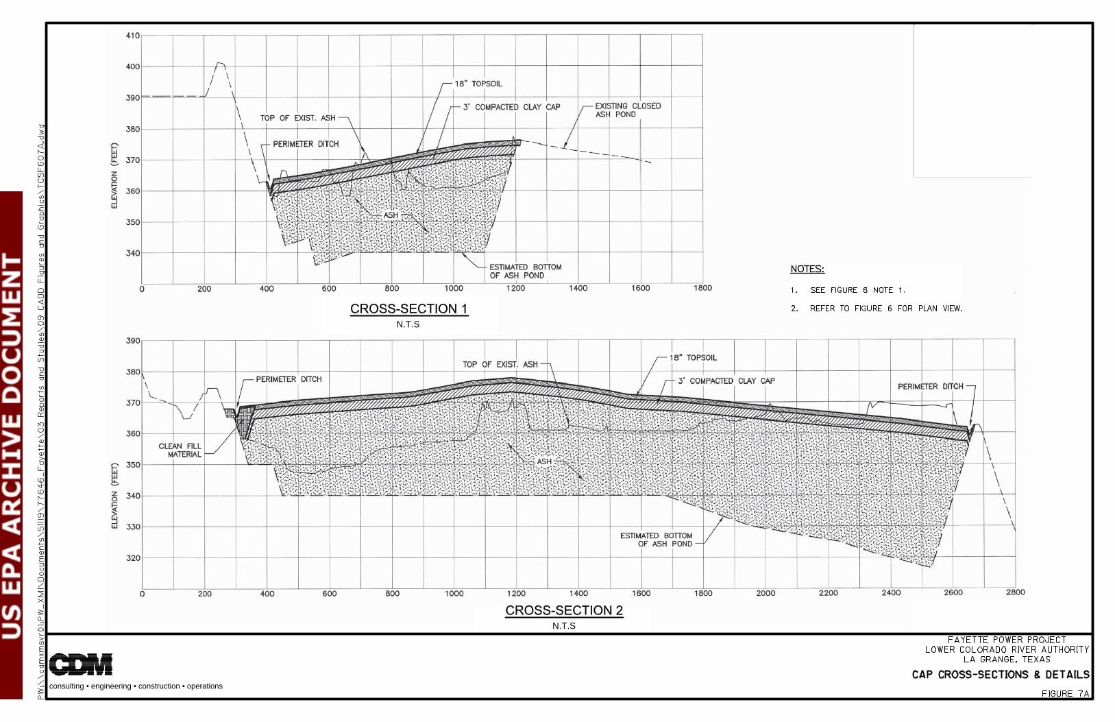
1.4.3 Future CCW Impoundment Configuration LCRA is in the process of installing a dry collection and disposal system for bottom ash, economizer ash, and air pre-heater ash for Units 1 and 2 at FPP. The Unit 2 dry collection system was installed in the spring of 2010, and the Unit 1 dry collection system is scheduled to be installed by the fall of 2010. No water or CCW will be disposed of in the CADP after October 2010. At that time and subject to TCEQ approval, LCRA plans close the CADP at FPP in accordance with TCEQ regulations, as shown on Figures 6 and 7.
Several structures currently used are part of the CADP management and operations, and are located in the active portion of the CADP. These structures include the concrete pump and motor pit, concrete settling basins, piping, pumps, motors, conduits, cable, fencing, spray headers, and additional water handling equipment. LCRA’s closure plan indicates the concrete structures will remain in-place and the other non-concrete structures will be removed, cleaned as necessary, and reused or recycled as applicable.
LCRA’s closure plan indicates the active portion of the impoundment will be dewatered to the extent practical before proceeding with other closure activities. The closure plan also indicates that ash sediments in the impoundment will be stabilized using on-site newly generated fly ash or fly ash from the CBL. LCRA performed laboratory bench-scale treatability studies to evaluate the strength of the stabilized ash sediments using new fly ash and/or fly ash from the CBL.
The closure plan indicates fly ash may also be borrowed from the CBL and used as general fill to achieve the lines and grades shown on the closure plan drawings. The proposed cover system will have final grades sloped at 1% to 4.5% to provide positive surface water drainage.
In the closure plan LCRA states ash fill material will be scarified to a minimum depth of two (2) inches prior to placement of the initial clay layer as part of the cap construction. The compacted clay cap for the closure of the active portion of the impoundment will be constructed using suitable clay material that is specified to have at least 20% passing No. 200 sieve and 90% passing No. 4 sieve, and no particles larger than two (2) inches in diameter. In accordance with TCEQ’s Technical Guideline (TG) No. 3, the compacted clay cap will be a minimum of three (3) feet thick and will have a maximum permeability of 1x10⁻⁷ cm/sec. LCRA states the material will be placed in 6 to 9 inch thick lifts and be compacted to a minimum 95% of the Standard Proctor maximum dry density per ASTM Method D-698 at a moisture content of 1% or greater above optimum to achieve a maximum permeability of 1x10⁻⁷ cm/s. LCRA states an 18-inch-thick uncompacted layer of topsoil will be placed on the compacted

Section 1 Introduction & Project Description
Fayette Power Project Assessment of Dam Safety of Coal Combustion Surface Impoundments
A 1-8
clay cap as recommended by TCEQ TG No. 3. The topsoil layer will be seeded with self-sustaining indigenous shallow root grass.
To control surface water run-off, LCRA plans to construct flat-bottom perimeter drainage ditches along the west, north, and east embankment crest where the new cap will tie into the existing embankments. The ditches will be graded to flow towards the northeast corner. In the northeast, a new stormwater spillway structure, similar to the southern spillway structure in the closed portion, will be constructed. In accordance with TCEQ’s TG No. 3, all stormwater management features will be designed to handle a 24-hour, 100-year rainfall event.
1.4.4 Other Impoundments In addition to the Coal Ash Disposal Pond and Reclaim Pond, there is a Coal Pile Run-off Pond at the FPP site. The Coal Pile Run-off Pond receives surface water run-off from the coal piles and is located adjacent to the south embankment toe of the Coal Ash Pond. Plant personnel indicated that there is no CCW stored in the Coal Pile Run-off Pond and that there is no direct pipe or other means to introduce CCW to the Coal Pile Run-off Pond.
The Coal Pile Run-off Pond is incised and has a crest at El. 360. The Coal Pile Run-off Pond embankments have a 20-foot-wide crest with 3H:1V side slopes on both the interior and exterior. A sand chimney drain discharges to a lateral toe drain connected to the CADP east embankment toe drain.
Surface water collected in the pond is normally discharged through a low-level outlet pipe consisting of a 12-inch-diameter ductile iron (DI) pipe. There is also an emergency spillway at elevation El. 354. The emergency spillway consists of a fabric formed concrete lined trapezoidal weir with a base width of 20 feet and 1H:1V side slopes.
1.5 Previously Identified Safety Issues Based on a review of the information provided to CDM and as reported by EPA, there have been no identified dam safety issues at FPP within the last ten (10) years.
1.6 Site Geology The FPP is located at the edge of the Gulf of Mexico coastal plain, near the contact with the coastal uplands. In the vicinity of the site the surficial geology consists of Miocene age deposits of the Oakville Formation of the Flemming Group. Typically, the sediments are interbedded sands, silts, and clays with intermixed volcano-clastic and tuffaceous material. In the vicinity of the site, medium stiff to hard calcareous, slickensided clays are predominately encountered from the surface to approximately El. 340, underlain by dense clayey sand and fine sand. The sand is underlain by stiff to hard calcareous, slickensided clay. The clay is underlain by sandstone below elevation El. 165.

A 2-1
Section 2 Field Assessment 2.1 Visual Observations CDM performed a visual assessment of the CCW impoundments at Fayette Power Project. The perimeter embankments of the impoundments total approximately 12,442 feet in length and are up to 62 feet high. The assessments were completed following the general procedures and considerations contained in Federal Emergency Management Agency’s (FEMA’s) Federal Guidelines for Dam Safety (April 2004) relative to observations concerning settlement, movement, erosion, seepage, leakage, cracking, and deterioration. A Coal Combustion Dam Inspection Checklist and CCW Impoundment Inspection Form, developed by USEPA, were completed on-site for each impoundment during the site visit. Copies of these forms are included in Appendix A. Photograph location plans are shown on Figures 8 and 9, and photographs are included in Appendix B.
It should be noted that tall or thick vegetation in some areas obscured visual observations of the exterior embankments.
CDM visited the site on June 23, 2010 and June 24, 2010 to make visual observations of the impoundments. The weather during the site visit was sunny with high temperatures of approximately 93 and 87 degrees Fahrenheit, respectively. Prior to the site visit, the following precipitation occurred as shown in Table 1.
Table 1 – Approximate Precipitation Prior to Site Visit Dates of Site Visit – June 23, 2010 & June 24, 2010
Day Date Precipitation (inches) Wednesday June 16 0.0 Thursday June 17 0.0
Friday June 18 0.0 Saturday June 19 0.0 Sunday June 20 0.0 Monday June 21 0.0 Tuesday June 22 0.0
Wednesday June 23 0.0 Thursday June 24 0.04
Total Week Prior to Site Visit 0.0 Total Month Prior to Site Visit 3.05
Notes: 1. Precipitation data from FPP rainfall measurements.
Section 2 Field Assessment
Fayette Power Project Assessment of Dam Safety of Coal Combustion Surface Impoundments
A 2-2
2.2 Reclaim Pond 2.2.1 Exterior Slope The Reclaim Pond is incised in the west and south embankment areas.
The exterior slope on the north appears to be in fair condition (Photos 2, 27, 34, 37, 38, 39, 40, 41, and 42). The grass on the north embankment ranged from 12 to 36 inches in height. Some minor brush and huisache bushes were observed on the slope. Brush and trees were observed at the toe of the slope in the drainage ditch. Desiccation cracks up to a ½ inch wide and eight (8) inches deep were observed at various locations on the slope.
The exterior slope on the east embankment is generally poor (Photos 43, 44, 46, 47, 48, 50, and 51).The grass on the east embankment ranged from 12 to 36 inches in height. Brush and mesquite trees, including one large diameter tree, were observed on the embankment, although most trees were smaller in diameter. Desiccation cracks up to a ½ inch wide and 8 inches deep were observed at various locations on the embankment. A fly ash surfaced access road was observed on the exterior slope of the embankment (Photos 48 and 50).
2.2.2 Crest The crest of the Reclaim Pond generally appeared to be in fair condition (Photos 3, 6, 7, 8, 10, 13, 14, 15, 16, 20, 23, 26, 35, 45, and 49). The crest was surfaced with compacted gravel around the perimeter of the impoundment and served as an access road. Some minor rutting was observed on the south and west embankment crest. The railroad spur ballast on the east embankment crest is approximately two (2) to three (3) feet above the access road. The water level was at approximately El. 366 and there was about four feet of freeboard at the time of the site visit.
2.2.3 Interior Slope The visible portions of the interior slope generally appeared to be in fair condition (Photos 1, 4, 5, 9, 11, 12, 14, 17, 18, 19, 20, 21, 22, 24, 25, 33, and 36). The interior slope is protected with riprap armor. Some minor brush was growing between the riprap on the east embankment interior slope. On the west and east embankment, there were some areas with little or missing riprap and there were areas with sparse vegetation and bare spots near the crest.
On the east embankment, there was one 2.5-foot-wide erosion rill (Photo 22). There was also an area where an abandoned 12-inch-diameter HDPE pipe from the CADP discharged into the Reclaim Pond. This area of the interior slope was eroded and some of the riprap was missing.
The waste drain trench (Photo 1) on the north embankment that drains into the impoundment was clear of debris and the channel was in good condition. The culvert

Section 2 Field Assessment
Fayette Power Project Assessment of Dam Safety of Coal Combustion Surface Impoundments
A 2-3
headwall on the west embankment that discharges into the impoundment appears to be in good condition. There was some FGD residue build-up on the apron of the headwall.
The 6-inch-diameter HDPE pipe from the CADP was in good condition. No water from the CADP was being discharged into the Reclaim Pond during the site visit.
2.2.4 Spillway The emergency spillway appeared to be in fair condition (Photos 28, 29, 30, 31, and 41). The concrete lining was in good condition. The spillway discharge channel had some minor grass growing in the channel. The entrance to the spillway channel had excessive vegetation and there was missing riprap. There was also excessive vegetation in the outlet channel.
2.2.5 Reclaim Pump Station and Evaporation System The reclaim pond pump station appeared to be in fair condition. The concrete lining was in good condition. One of the return lines from the pump station had a small leak in the line.
There is a manual and electronic staff gauge in Reclaim Pond. The pond water levels are recorded twice a day and reported in a daily status report that is electronically mailed to pertinent staff
The evaporation spray piping system appeared to be in good condition. The system was shut off during the visual inspection of the impoundment.
2.3 Coal Ash Disposal Pond 2.3.1 Exterior Slope The CADP is incised on the north and west embankments. The south and east exterior slopes appear to be generally in fair condition (Photos 53, 54, 55, 57, 58, 60, 61, 62, 67, 68, 69, 71, 73, 74, 77, 78, and 85). The grass on the embankment was approximately 8 to 12 inches tall and was recently mowed. Trees and brush up to 6 inches in diameter were observed at the toe of the south embankment in the Coal Pile Run-off Pond. There were some bare spots near the middle of the south embankment exterior slope (Photo 81).
CDM observed 16 rodent holes, reportedly made by armadillos, on the east embankment exterior slope. The holes ranged in size from 4 to 8 inches in diameter (Photos 63 and 65). There were also multiple surface depressions that were likely rodent holes that collapsed, possibly as a result of mowing operations (Photos 62, 79, 80, and 84).
Two of the toe drain outlets from the chimney drain on the east embankment were observed (Photos 64 and 66). The toe drain shown in Photo No. 66 also connects to a
Section 2 Field Assessment
Fayette Power Project Assessment of Dam Safety of Coal Combustion Surface Impoundments
A 2-4
third toe drain (not photographed) that collects drainage from the portion of the chimney drain associated with the Coal Pile Run-off Pond embankment. Both of these toe drains discharge into a seepage collection sump pit, referred to as the Lateral Drain Sump. Water collected in the Lateral Drain Sump is pumped back into the impoundment. Seepage was not observed in the sump pit during the site visit. The ground around the other discharge pipe (Photo No. 64) was damp, although no significant seepage was observed.
An active seep on the south embankment exterior slope was observed (Photos 82 and 83). LCRA has constructed a containment structure to collect the seepage water. The estimated flow from the seep typically ranges from 8 to 11 gallons per day based on review of information provided by LCRA personnel
2.3.2 Crest The crest of the CADP appeared to be generally in fair condition (Photos 53, 56, 59, 72, 75, 86, 89, 90, 91, 99, 100, 101, 102, 103, and 104). The crest surface consisted of gravel road base material and was used as an access road. Some minor rutting and depressions were observed on the east and west embankment crest. A tension crack in the previously raised portion of the crest was observed on the north embankment (Photo 99). The chain link fence and posts appeared to be holding the raised section of the crest preventing it from sloughing. The water level was at about El. 355 and there was approximately seven (7) feet of freeboard at the time of the site visit.
2.3.3 Interior Slope The majority of the interior slope was not visible since the impoundment was filled with ash to nearly the crest elevation. The southern portion of the impoundment is capped and the slopes are covered with grass. Northern portions of the interior slopes are typically covered with CCW and grass has grown onto the material. The visible portions of the interior slope generally appeared to be in fair condition (Photos 59, 87, 88, 90, 91, 94, 95, 96, 97, 98, 103, 104, and 105). The grass on the inside of the embankment was approximately 8 to 12 inches tall and was recently mowed.
The primary settling basin area appeared to be in good condition. Two sets of two (2) 12-inch-diameter Asholite composite discharge pipes sluice CCW into the settling basins. CCW is sluiced into one basin at a time. The Marketer responsible for beneficial reuse of the ash is also responsible for dredging the settling basins and stockpiling the CCW material to dewater. The Marketer has dredged and stockpiled CCW inside the impoundment to create a stream to lengthen the settling time before entering the main pool area. The stockpiles of CCW observed were up to 15 feet higher than the crest of the perimeter embankment. Some of the stockpiled material is within 100 feet of the crest.

Section 2 Field Assessment
Fayette Power Project Assessment of Dam Safety of Coal Combustion Surface Impoundments
A 2-5
2.3.4 Intake Structure and Evaporation System The intake structure for the evaporation system appeared to be in fair condition. The concrete was not cracked or spalled. The pumps were off during the visual inspection of the impoundment.
On the northwest corner of the intake structure there are two manual staff gauges in the CADP (Photos 92 and 93). The pond water levels are recorded twice a day and reported in a daily status report that is electronically mailed to pertinent staff.
A 3-1
Section 3 Data Evaluation 3.1 Design Assumptions CDM has reviewed information provided by LCRA related to the original design assumptions and analyses completed subsequent to the original design of the CCW impoundments.
3.2 Hydrologic and Hydraulic Design LCRA provided CDM with the hydrologic and hydraulic analyses for the CADP. Bechtel (1976) evaluated the hydraulic capacity of the original impoundment to store a design storm event. Based on Texas Administrative Code Title 30 Chapter 299 (Dams and Reservoirs), the impoundments would be categorized as intermediately sized, low hazard structures. Such structures with drainage areas less than 10 square miles are required to pass 25 to 50% of the PMF, for a minimum 1-hour storm event based on Chapter 299 and “Hydrologic and Hydraulic Guidelines for Dams in Texas”, TCEQ, January 2007 (HHG). However, the CADP has no spillway therefore Bechtel evaluated the impoundment for the full Probable Maximum Flood (PMF). The original contributory drainage area for the CADP was 112 acres for the 83.87 acre impoundment. Bechtel evaluated the impoundments’ ability to store the water from the PMF event resulting from approximately 45.3 inches of rainfall.
The southern 39.65 acres of the CADP were capped in 1988, and surface water flow on the capped section has been directed away from the impoundment. The remaining drainage area is approximately 72.35 acres, resulting in surface runoff of 273.12 acre-ft flowing into the active impoundment. Currently the available pond area is approximately half that of the active impoundment resulting in 22.11 acres of storage area. Assuming the impoundment is normally operated at elevation El. 355, the impoundment can only safely store approximately 154.77 acre-feet of runoff. Therefore, until the CADP is capped, the impoundment does not have enough capacity to safely store a PMF event and would be overtopped.
TCEQ requires a minimum of two (2) feet of freeboard to be maintained. Bechtel (1976) determined that a minimum of 3.7 feet of freeboard is required to accommodate wave action. The 3.7 feet was based on wave action resulting from an 80 MPH wind.
LRCA did not provide CDM with the hydrologic and hydraulic analyses for the Reclaim Pond. CDM completed a preliminary evaluation of the hydraulic capacity of the impoundment to estimate if the pond is adequately sized to store or pass the design storm event. The drainage area contributing to the Reclaim Pond is approximately 40 acres plus additional routed flow from plant areas. The contributing drainage area is significantly less than ten (10) square miles. The HHG indicates that for drainage areas less than ten (10) square miles, the PMF is to be developed by applying the total depth of the Probable Maximum Precipitation (PMP) from

Section 3 Data Evaluation
Fayette Power Project Assessment of Dam Safety of Coal Combustion Surface Impoundments
A 3-2
Hydrometeorological Reports 51 and 52 (HMR-51 and HMR-52) to the entire drainage area for all storm durations. The six (6)-hour, ten (10) square mile PMP is approximately 31 inches. Where the drainage area is approximately the pond area, CDM assumed that the PMP is equal to the PMF for the purpose of evaluating impoundment storm capacity. Based on a normal pool level of El. 365, preliminary evaluations indicate that there is enough storage capacity and freeboard in both impoundments to store a 100% of the PMF event without being overtopped.
3.3 Structural Adequacy and Stability
Texas Administrative Code Title 30, Chapter 299 (Dams and Reservoirs) requires new and existing dams be evaluated under standard design guidelines. CCW impoundments, however, are exempt from the above-referenced regulations.
The CCW impoundments at FPP are registered Class 2 waste management units according to the TCEQ. The TCEQ requires Class 2 waste management units to:
Prevent washout, release, or exposure of waste; Have a minimum factor of safety for slope stability of 1.3; and Be hydrostatically and hydrodynamically stable against storms and floods.
In addition to the above requirements, procedures established by the United States Army Corps of Engineers (USACE), the United States Bureau of Reclamation, the Federal Energy Regulatory Commission, and the United States Natural Resources Conservation Service are generally accepted engineering practice. Minimum required factors of safety outlined by the USACE in EM 1110-2-1902, Table 3-1 and seismic factors of safety by FEMA Federal Guidelines for Dam Safety, Earthquake Analyses and Design of Dams (pgs. 31, 32 and 38, May 2005) are provided in Table 2.
Table 2 – Minimum Safety Factors Required
Load Case Minimum Required Factor of Safety
Steady-State Condition at Normal Pool or Maximum Storage Pool Elevation
1.5
Rapid Drawdown Condition from Normal Pool Elevation 1.2 Maximum Surcharge Pool (Flood) Condition 1.4 Seismic Condition from at Normal Pool Elevation 1.0 Liquefaction 1.3
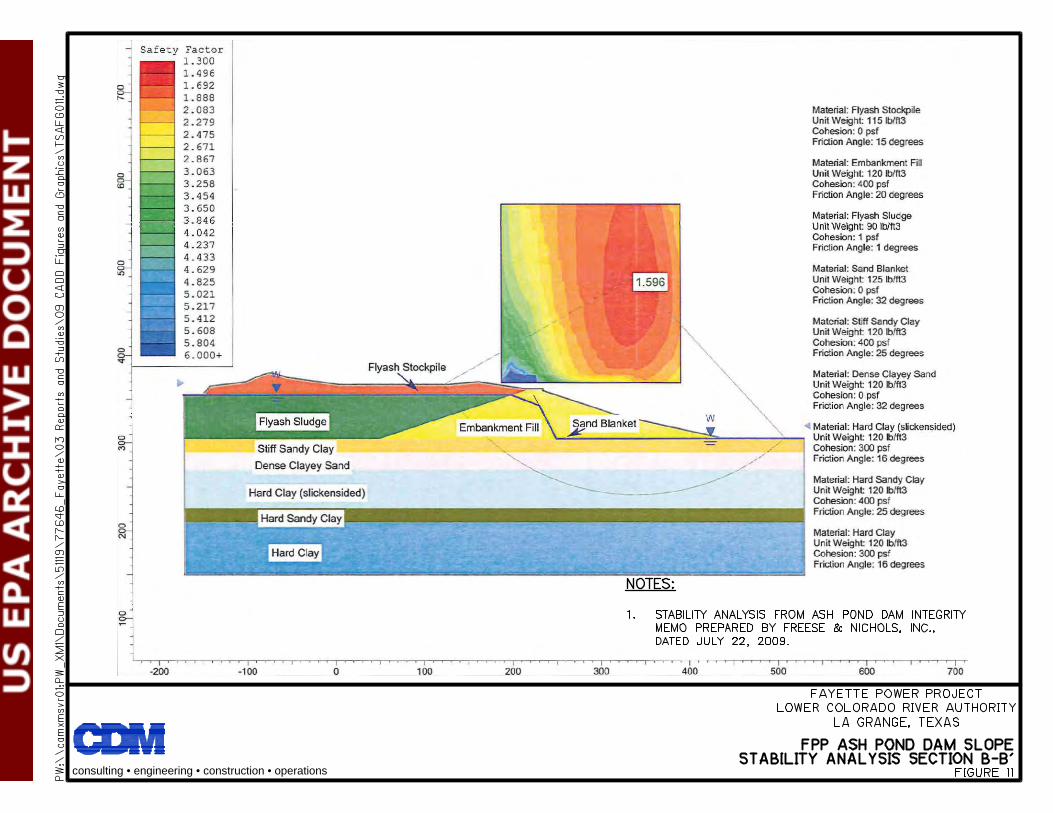
Freese and Nichols, Inc. (FNI) in conjunction with Fugro Consultants, Inc. (FCI) prepared a Condition Assessment on the slope stability of the CADP east embankment, dated July 22, 2009. Analyses were performed for long-term steady-state conditions at normal pool level for the active and capped portion of the east embankment. Soil parameters used for the analyses and analysis results are presented on Figures 10 and 11. The results on Figure 10 and 11 indicate the factor of safety

Section 3 Data Evaluation
Fayette Power Project Assessment of Dam Safety of Coal Combustion Surface Impoundments
A 3-3
against slope stability was about 1.60 and 1.70 for the active and capped portion of the east embankment exterior slope, respectively.
LCRA discovered a seep on the south embankment exterior slope of the CADP in March 2010. In response, LCRA contracted FNI to perform three (3) test borings on the crest of the south embankment, install monitoring wells, and perform additional slope stability analyses to evaluate the stability of the embankment. At the time of the site visit, LCRA had not received the results of the additional stability analysis from FNI. LCRA personnel stated they expected the results from FNI in July.
Although the embankment was stable under normal loading conditions, FNI’s evaluation did not consider the following load cases:
Maximum surcharge pool (flood) condition; Rapid drawdown condition; Seismic loading; or Liquefaction.
No stability analysis results were provided for the Reclaim Pond.
3.4 Foundation Conditions Based on the original 24 test borings performed by National Soil Services, Inc., and three (3) recent test borings performed by Fugro, the embankments for the CADP were constructed over surface deposits of medium stiff to hard, sandy clay underlain by medium dense, clayey sand and fine sand. The clayey soils ranged in thickness from 5 to greater than 20 feet and ranged in permeability from 4.0x10⁻⁹ cm/sec to 5.92x10⁻⁷ cm/sec. The drawings and geotechnical report prepared by Bechtel indicate the site was to be stripped prior to constructing the embankments. Based on the documents reviewed, the in-situ soil was intended to be used to construct pond liners. The design report by Bechtel indicated the subgrade was to be scarified, disked, and compacted prior to placement of the first lift of fill. Loose thickness of each lift of fill was to be limited to the maximum which would result in a compacted thickness not greater than nine inches. The fill was specified to be compacted to at least 95% of the “Bechtel” modified density and within minus 2% to plus 3% of the optimum moisture content. The design report also indicated that at least six passes of rolling equipment were required, provided that the specified density was developed.
Based the original eight (8) test borings performed by National Soil Services, Inc., and 36 test borings later performed by McCelland Engineers, Inc., the embankments for the Reclaim Pond were constructed over surface deposits of medium stiff to hard, sandy clay underlain by medium dense, clayey sand and fine sand. The railroad embankments were constructed based on Bechtel’s 1976 design recommendations, described above. The impoundment drawings prepared by Black & Veatch in 1989 indicate the site was to be stripped a minimum of 12 inches prior to constructing the
Section 3 Data Evaluation
Fayette Power Project Assessment of Dam Safety of Coal Combustion Surface Impoundments
A 3-4
embankments. Based on the documents, the in-situ soil was intended to be reused to construct a pond liner with permeability ranging from 2.5x10⁻⁹ cm/sec to 3.2x10⁻⁷ cm/sec. The drawings indicated a minimum of 12 inches of the subgrade was to be recompacted prior to placement of the first lift of fill. The fill was specified to be compacted to at least 95% of the standard Proctor, ASTM D 698.
3.5 Operations and Maintenance LCRA indicated that they have written operating plans for the impoundments. The operators are also provided with formal training classes before being assigned their duties relative to the impoundments, and junior operators are partnered with senior operators as part of the training process. The Operator’s perform visual inspections twice a day (one per shift) and record the water levels in the impoundments. Observations are reported in a daily status report sent out via electronic mail. Trained plant personnel also perform quarterly inspections and document inspection results on a formal written inspection record. The inspection record includes instructions and guidance for the inspector’s use. Water levels in the monitoring wells around the CADP and Reclaim Pond are recorded semi-annually. Areas of concern identified during inspections are physically flagged in the field, documented, and photographed. Corrective action is taken as necessary to remedy the identified issues. Significant issues are given high priority and repaired as soon as possible. An in-house professional dam engineer also performs a detailed annual inspection.
Routine maintenance performed includes mowing grass and other activities as needed to address other observed conditions such as erosion, rodent burrows, and revegetation. Mowing is subcontracted and is typically performed at least four (4) times per year.
LCRA has no formal emergency action plan (EAP) for the impoundments.
A 4-1
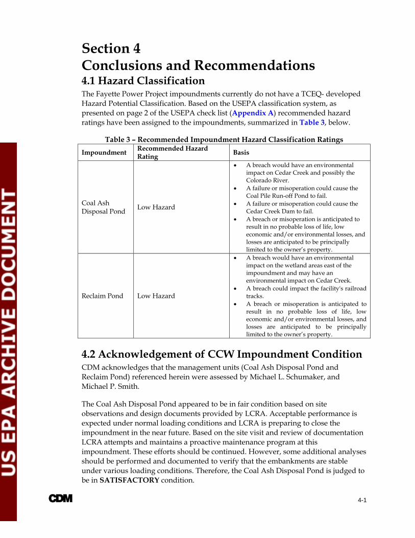
Section 4 Conclusions and Recommendations 4.1 Hazard Classification The Fayette Power Project impoundments currently do not have a TCEQ- developed Hazard Potential Classification. Based on the USEPA classification system, as presented on page 2 of the USEPA check list (Appendix A) recommended hazard ratings have been assigned to the impoundments, summarized in Table 3, below.
Table 3 – Recommended Impoundment Hazard Classification Ratings
Impoundment Recommended Hazard Rating
Basis
Coal Ash Disposal Pond
Low Hazard
A breach would have an environmental impact on Cedar Creek and possibly the Colorado River.
A failure or misoperation could cause the Coal Pile Run-off Pond to fail.
A failure or misoperation could cause the Cedar Creek Dam to fail.
A breach or misoperation is anticipated to result in no probable loss of life, low economic and/or environmental losses, and losses are anticipated to be principally limited to the owner’s property.
Reclaim Pond Low Hazard
A breach would have an environmental impact on the wetland areas east of the impoundment and may have an environmental impact on Cedar Creek.
A breach could impact the facility's railroad tracks.
A breach or misoperation is anticipated to result in no probable loss of life, low economic and/or environmental losses, and losses are anticipated to be principally limited to the owner’s property.
4.2 Acknowledgement of CCW Impoundment Condition CDM acknowledges that the management units (Coal Ash Disposal Pond and Reclaim Pond) referenced herein were assessed by Michael L. Schumaker, and Michael P. Smith.
The Coal Ash Disposal Pond appeared to be in fair condition based on site observations and design documents provided by LCRA. Acceptable performance is expected under normal loading conditions and LCRA is preparing to close the impoundment in the near future. Based on the site visit and review of documentation LCRA attempts and maintains a proactive maintenance program at this impoundment. These efforts should be continued. However, some additional analyses should be performed and documented to verify that the embankments are stable under various loading conditions. Therefore, the Coal Ash Disposal Pond is judged to be in SATISFACTORY condition.
Section 4 Conclusions/Recommendations
Fayette Power Project Assessment of Dam Safety of Coal Combustion Surface Impoundments
A 4-2
The Reclaim Pond appears to be generally in fair condition, with exception of the east embankment. There is also a lack of documentation relative to the design and construction of this impoundment. It is not known if critical studies or investigations (complete stability analyses, hydrologic, hydraulic, seismic evaluations) have been performed to confirm that potential safety deficiencies do not exist. Therefore, the Reclaim Pond is judged to be in POOR condition. Additional documentation and future studies performed to confirm the condition and performance of these impoundments may be sufficient to substantiate an improved condition assessment.
Discussed in the following sections are deficiencies and recommendations for further studies. Maintenance and monitoring may further improve the condition of these impoundments.
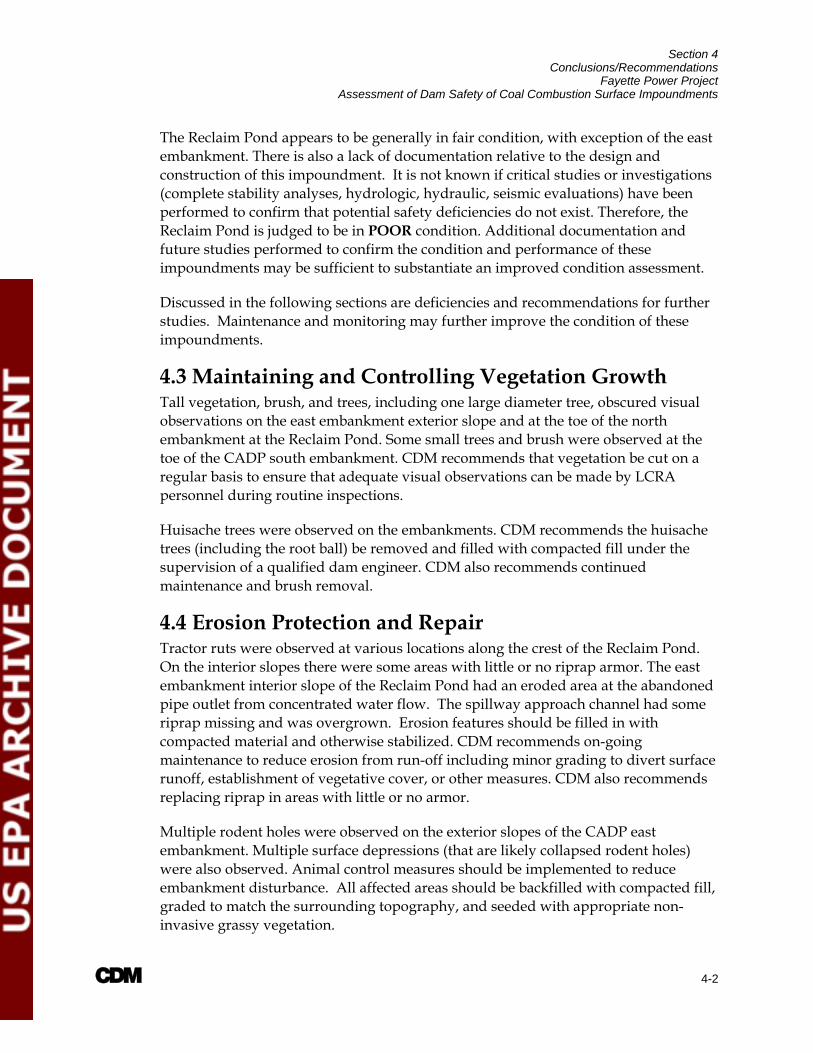
4.3 Maintaining and Controlling Vegetation Growth Tall vegetation, brush, and trees, including one large diameter tree, obscured visual observations on the east embankment exterior slope and at the toe of the north embankment at the Reclaim Pond. Some small trees and brush were observed at the toe of the CADP south embankment. CDM recommends that vegetation be cut on a regular basis to ensure that adequate visual observations can be made by LCRA personnel during routine inspections.
Huisache trees were observed on the embankments. CDM recommends the huisache trees (including the root ball) be removed and filled with compacted fill under the supervision of a qualified dam engineer. CDM also recommends continued maintenance and brush removal.
4.4 Erosion Protection and Repair Tractor ruts were observed at various locations along the crest of the Reclaim Pond. On the interior slopes there were some areas with little or no riprap armor. The east embankment interior slope of the Reclaim Pond had an eroded area at the abandoned pipe outlet from concentrated water flow. The spillway approach channel had some riprap missing and was overgrown. Erosion features should be filled in with compacted material and otherwise stabilized. CDM recommends on-going maintenance to reduce erosion from run-off including minor grading to divert surface runoff, establishment of vegetative cover, or other measures. CDM also recommends replacing riprap in areas with little or no armor.
Multiple rodent holes were observed on the exterior slopes of the CADP east embankment. Multiple surface depressions (that are likely collapsed rodent holes) were also observed. Animal control measures should be implemented to reduce embankment disturbance. All affected areas should be backfilled with compacted fill, graded to match the surrounding topography, and seeded with appropriate non-invasive grassy vegetation.

Section 4 Conclusions/Recommendations
Fayette Power Project Assessment of Dam Safety of Coal Combustion Surface Impoundments
A 4-3
4.5 Impoundment Hydraulic and Stability Analysis LCRA did not provide CDM with a current hydraulic analysis of the CADP demonstrating the ability of the impoundments to safely pass the applicable design storm, which appears to be the full PMF event based on Bechtel (1976). However, LCRA has submitted a closure plan to TCEQ to close the CADP. It is our understanding that the cap for the CADP is being designed to handle run-off for a 24-hour, 100-year rainfall event.
LCRA did not provide CDM with a hydraulic analysis of the Reclaim Pond demonstrating the ability of the impoundments to store safely pass or store the applicable design storm, which appears to be the 50% PMF event. However, a preliminary evaluation performed by CDM suggests there is enough storage capacity at the current operating pool levels to safely store precipitation from the full PMF. CDM recommends LCRA perform a detailed study to confirm this conclusion and update the study if operating levels of the pond change in the future.
Based on CDMs review of available information for the impoundments, the following analyses are recommended to be performed to confirm that the embankments are adequately stable under the loading conditions outlined in Section 3.
Coal Ash Disposal Pond
Evaluate the stability of the embankment under seismic conditions, including an evaluation of liquefaction potential of stored fines, at proposed water levels after closure.
Reclaim Pond
Evaluate the stability of the north and east embankment under various appropriate loading conditions. Representative cross-sections of the embankment should be evaluated.
Evaluate the stability of the embankments under normal pool and maximum surcharge pool (flood) conditions.
Evaluate the stability of the interior and exterior slopes under seismic loading, including an evaluation of the liquefaction potential of stored fines and steady state seepage loading conditions.
Perform a liquefaction potential analysis.
Evaluate the stability of the interior slope under rapid drawdown loading conditions. While a rapid drawdown is not a scenario that has a high probability of occurrence, it should be demonstrated that this condition meets

Section 4 Conclusions/Recommendations
Fayette Power Project Assessment of Dam Safety of Coal Combustion Surface Impoundments
A 4-4
the industry recommended factor of safety in the event that a catastrophic condition develops whereby a rapid drawdown situation occurs.
4.6 Instrumentation Water levels in the CADP and Reclaim Pond are recorded twice daily by LCRA personnel. Plant personnel also record water levels in the monitoring wells around the CADP and Reclaim Pond on a semi-annual basis. CDM recommends that an updated monitoring well network plan be prepared to identify the locations of all functioning wells so that they can be utilized to monitor future water levels.
Four monitoring wells are reportedly located on the crest of the CADP east embankment. CDM recommends the monitoring wells be located in the field and returned to service or that they be properly abandoned.
4.7 Seepage Control and Closure Dewatering Minor amounts of seepage were observed at the CADP, including the seep that is currently being contained. LCRA’s current seepage containment system does not appear to be a viable long-term solution once the impoundment is closed. An alternative method of collecting and managing the seepage should be evaluated as part of the closure plans.
In addition, CDM recommends LCRA investigate the hydraulic connection between the impoundment and the Cedar Creek Dam as part of the closure design in order to evaluate potential impacts resulting from changes in groundwater levels and pore water pressures. Where the impoundment is built on the downstream slope of the dam, dewatering activities performed to stabilize the CCW and construct the cap may impact the phreatic level within the embankment of the dam. Changes to the phreatic level in the Cedar Creek Dam may result in potentially unstable slopes, settlement, or other undesirable consequences. Dewatering of CCW during closure activities should be staged to prevent excess pore pressure build-up and conducted in a manner to prevent significant seepage gradients, which could affect the stability of the Cedar Creek Dam. LCRA should also evaluate the anticipated long-term seepage from the Cedar Creek Dam into the impoundment and its impact on closure.
4.8 Inspection Recommendations Based on the information reviewed by CDM, it appears LCRA has adequate inspection practices for the CADP. Inspections are performed routinely and documented via daily status reports. Detailed inspections are documented and are completed for the CADP on a quarterly basis. Annual inspections are completed by an engineer. LCRA should also perform inspections in a similar manner for the Reclaim Pond. It is recommended that the quarterly inspection records be retained at the facility for a minimum of three (3) years.

Section 4 Conclusions/Recommendations
Fayette Power Project Assessment of Dam Safety of Coal Combustion Surface Impoundments
A 4-5
4.9 Operations There is no formal operation and maintenance manual for the impoundments. CDM recommends that written operation and maintenance guidelines be developed outlining procedures for the maintenance of the embankments and operational procedures for the impoundments and appurtenant structures.
There is no formal emergency action plan (EAP) for the impoundments. Both impoundments have a low hazard classification. However, failure or misoperation of the impoundments could result in a condition that needs to be managed from an environmental and property damage standpoint. Detailed emergency action procedures should be developed to identify roles and responsibilities and to facilitate internal and external communication necessary to manage an impoundment failure. The procedures should include coordination with Cedar Creek Dam operations in event of an unintended release or breach of the impoundments, since failure of the Coal Ash Disposal Pond or the Coal Pile Run-off Pond could have adverse effects on the dam.
4.10 Closure Recommendations The closure plan indicates proposed grades for the new cap will range from 1% to 4.45%. TCEQ TG No. 3 recommends final covers are graded with sufficient slopes to provide positive drainage, typically between 3% and 5%. Common practice is to create a minimum of a 2% slope to allow for surface water conveyance and prevent pooling. In addition, a 1% grade is difficult to construct and differential settlement in the CCW could result in low areas and subsequent pooling if such a small grade is used. CDM recommends that LCRA evaluate the slope of the cap and potential future settlement to ensure that the cap functions as intended.

A 5-1
Section 5 Closing The information presented in this report is based on visual field observations and review of reports and data provided to CDM by LCRA for the Fayette Power Project surface impoundments. The conclusions and recommendations presented are based, in part, on limited information available at the time of this report. This report has been prepared in accordance with generally accepted engineering practices. No other warranty, expressed or implied, is made. Should additional information become available or changes in field conditions occur, the conclusions and recommendations provided in this report should be re-evaluated by a qualified professional engineer.

A 6-1
Section 6 Reports and References The following is a list of reports and drawings that were reviewed during the preparation of this report and the development of the recommendations presented herein.
1. AMEC Geomatrix, April 30, 2010, Proposed Monitoring Well and Piezometer Location Plan
2. AMEC Geomatrix, May 14, 2010, Potentiometric Surface Map of Middle Sand July 2009
3. Bechtel Power Corporation, October 20, 1976, Drawing No. A-C-230-G19, “Ash Disposal Pond Plan”
4. Bechtel Power Corporation, October 20, 1976, Drawing No. A-C-230-G20, “Ash Disposal Sections”
5. Bechtel Power Corporation, February 13, 1976, Drawing No. A-C-230-G21, “Ash Disposal Sections”
6. Bechtel Power Corporation, March 26, 1976, Drawing No. A-C-230-G22, “Ash Pond Dike Profiles and Details”
7. Bechtel Power Corporation, June 22, 1977, Drawing No. I-M-816-112,” Piping Plan Ash Water Pumphouse Area”
8. Bechtel Power Corporation, November 30, 1976, Drawing No. A-C-653-C01, “Ash Pond Intake Structure Conc. Plan, Section & Details – Sheet 1”
9. Bechtel Power Corporation, November 30, 1976, Drawing No. A-C-653-C02, “Ash Pond Intake Structure Conc. Plan, Section & Details – Sheet 2”
10. Bechtel Power Corporation, August 27, 1976, System Description Ash Pond and Coal Runoff Pond
11. Bechtel Power Corporation, May 20, 1977, Letter to Texas Water Quality Board
12. Black & Veatch, May 1, 1989, Drawing No. B-C-00G-022, “Site Grading Plans, Sections and Details”
13. Black & Veatch, May 1, 1989, Drawing No. B-C-00G-013, “Site Grading, Drainage, Roads, and Parking Area 2”
14. Black & Veatch, May 1, 1989, Drawing No. B-C-00G-014, “Site Grading, Drainage, Roads, and Parking Area 3”

Section 6 Reports and References
Fayette Power Project Assessment of Dam Safety of Coal Combustion Surface Impoundments
A 6-2
15. Federal Emergency Management Agency, March 3, 2008, Risk Prioritization Tool for Dams, Users Manual
16. Federal Emergency Management Agency, April 2004, Federal Guidelines for Dam Safety, Hazard Potential Classification System for Dams
17. Freese and Nichols, Inc , Ash Pond Interim Observation Memorandum LCR10205
18. Freese and Nichols, Inc., July 22, 2009, Ash Pond Containment Dam Integrity Assessment Memorandum
19. Fugro, June 14 and 15, 2010, Preliminary Ash Pond Seep Boring Logs
20. LCRA, June 24, 2010, FPP Daily Status Report
21. LCRA, January 29, 2009, Ash Pond History
22. LCRA, May 20, 2010, Ash Pond Seep Statement of Work
23. LCRA, updated June 23, 2010, Ash Pond Seep Record Spreadsheet
24. LCRA, April 23, 2009Ash Pond Closure Charter
25. LCRA, Ash Pond Embankment Inspection Documentation Form
26. LCRA, March 24, 2009, EPA Request for Information
27. TCEQ, March 10, 2009 , Compliance Evaluation Investigation
28. LCRA, February 28, 2008, Reclaim Pond and Coal Pond Bathymetric Survey
29. LCRA, Ash Pond Impoundment Management Plan
30. LCRA, January 1, 2009 through December 31, 200, FPP CCP Operating Report
31. LCRA, July 14, 2009, Notice of Registration
32. LCRA, September 29, 2000, Proof of Deed Recordation for Solid Waste Management Unit # 002 (Ash Pond) Industrial Solid Waste Registration # 32575 Fayette Power Project, La Grange, Texas,
33. LCRA, Ash Pond Partial Closure
34. LCRA, June 12, 2009, TPDES WW Permit WQ0002105000
35. LCRA, April 30, 2009, Contract for Grounds Maintenance: Mowing and Shedding

Section 6 Reports and References
Fayette Power Project Assessment of Dam Safety of Coal Combustion Surface Impoundments
A 6-3
36. LCRA, February 22, 1996, Units 1, 2 & 3 Plan Water Balance Plan
37. LCRA, 2009, Aerial Survey Pond Volume Calculations
38. LCRA, February 22, 1996, Storm water drainage plan (Figure 4)
39. LCRA, 2009, Aerial Survey Ash Pond
40. LCRA, 2009, Aerial Survey Coal Run-off Pond
41. McCelland Engineers, Inc, May 1983, Geotechnical Investigation Report, Reclaim Pond
42. National Soil Services, Inc., August 12, 1977, Soils Investigation Report, Ash Disposal Pond
43. National Soil Services, Inc., January 15, 1975, Foundation Investigation
44. Texas Administrative Code, Title 30, Chapter 299, Dams and Reservoirs
45. Texas Commission on Environmental Quality, August 2009, RG-473, Design and Construction Guidelines for Dams in Texas, Dam Safety Program
46. Texas Commission on Environmental Quality, January 2007, GI-364, Hydrologic and Hydraulic Guidelines for Dams in Texas, Dam Safety Program
47. Texas Water Development Board, February 2006, Chapter 2, Geology of the Gulf Coast Aquifer, Texas, Report 365: Aquifers of the Gulf Coast of Texas
48. Texas Water Development Board, February 2010, Hydrostratigraphy of the Gulf Coast Aquifer from the Brazos River to the Rio Grande
49. URS Corporation, July 2010, Ash Pond Closure Plan Fayette Power Project Solid Waste Registration #31575 Waste Management Unit #002
50. US Army Corps of Engineers, April 2008, National Inventory of Dams Methodology, State and Federal Agency Manual, Version 4.0

Figures

N
SITE
consulting • engineering • construction • operations

N
ROUTE 71BRIDGE
consulting • engineering • construction • operations
SITE
COLORADO RIVER
LAKE FAYETTE

consulting • engineering • construction • operations
TYPICAL CROSS-SECTION NORTH EMBANKMENT
TYPICAL CROSS-SECTION EAST EMBANKMENT
TYPICAL CROSS-SECTION SOUTH EMBANKMENT

consulting • engineering • construction • operations
TYPICAL CROSS-SECTION NORTH EMBANKMENT
TYPICAL CROSS-SECTION EAST EMBANKMENT

N
COAL PILERUN-OFF POND
consulting • engineering • construction • operations
ACTIVE COAL ASH POND
CLOSED COAL ASH POND
RECLAIM POND
LAKE FAYETTE

consulting • engineering • construction • operations
N.T.S
N
consulting • engineering • construction • operations
N.T.S
N.T.S

consulting • engineering • construction • operations
N.T.S
N.T.S

N
consulting • engineering • construction • operations
RECLAIM POND


consulting • engineering • construction • operations
consulting • engineering • construction • operations
Appendix A USEPA Coal Combustion Dam
Inspection Checklist Forms

Site Name: Date: Unit Name: Operator's Name: Unit I.D.: Hazard Potential Classification: High Significant Low Inspector's Name:
Check the appropriate box below. Provide comments when appropriate. If not applicable or not available, record "N/A". Any unusual conditions or construction practices that should be noted in the comments section. For large diked embankments, separate checklists may be used for different embankment areas. If separate forms are used, identify approximate area that the form applies to in comments.
Yes No Yes No
1. Frequency of Company's Dam Inspections? 18. Sloughing or bulging on slopes? 2. Pool elevation (operator records)? 19. Major erosion or slope deterioration? 3. Decant inlet elevation (operator records)? 20. Decant Pipes: 4. Open channel spillway elevation (operator records)? Is water entering inlet, but not exiting outlet? 5. Lowest dam crest elevation (operator records)? Is water exiting outlet, but not entering inlet? 6. If instrumentation is present, are readings recorded (operator records)? Is water exiting outlet flowing clear?
7. Is the embankment currently under construction? 21. Seepage (specify location, if seepage carries fines, and approximate seepage rate below):
8. Foundation preparation (remove vegetation,stumps, topsoil in area where embankment fill will be placed)? From underdrain? 9. Trees growing on embankment? (If so, indicate largest diameter below) At isolated points on embankment slopes? 10. Cracks or scarps on crest? At natural hillside in the embankment area? 11. Is there significant settlement along the crest? Over widespread areas? 12. Are decant trashracks clear and in place? From downstream foundation area? 13. Depressions or sinkholes in tailings surface or whirlpool in the pool area? "Boils" beneath stream or ponded water? 14. Clogged spillways, groin or diversion ditches? Around the outside of the decant pipe? 15. Are spillway or ditch linings deteriorated? 22. Surface movements in valley bottom or on hillside? 16. Are outlets of decant or underdrains blocked? 23. Water against downstream toe? 17. Cracks or scarps on slopes? 24. Were Photos taken during the dam inspection? Major adverse changes in these items could cause instability and should be reported for further evaluation. Adverse conditions noted in these items should normally be described (extent, location, volume, etc.) in the space below and on the back of this sheet.
Inspection Issue # Comments
Coal Combustion Dam Inspection Checklist FormUS EnvironmentalProtection Agency
EPA FORM -XXXX
Fayette Power Project Station June 24, 2010
Ash Pond Lower Colorado River Authority
Unit 002
Michael Smith, Michael Schumaker
see note 1
355
d/n/a
d/n/a
362
d/n/a
x
x
x
x
x
x
x
x
x
x
x
x
d/n/a
x
x
x
x
x
x
x
x
x
x
1. Informal rounds made twice a day. Detailed inspections performed quarterly. Inspections by in-house dam PE
performed annually.
2. Water levels are recorded twice a day and included in a plant daily status report.
6. Piezometers are read semi-annually.
8. Based on review of documents provided by plant personnel.
9. Up to 4-inch-diameter brush on south embankment at coal pile run-off pond.
10. and 17. Several ~1/4 to 1/2 inch wide by up to 12 inch deep dessication cracks on exterior slopes and crest. The
cracks were mainly parallel to the crest, variable length, and randomly located.
10. Approximate 16' long dessication crack on north embankment crest. The impoundment in this area is mainly
incised, the embankment is a limited height access road. The crack is present in fill placed to grade the road surface.
21. Minor seepage collected in toe drain system of east embankment and discharges into sump pit. No flow observed
during site visit. One isolated seep on exterior of south embankment, Qavg ~10 gal/day based on data provided.
23. Coal pile run-off pond at south embankment exterior toe.
n/a = Not Available
d/n/a = Does Not Apply
see note 6
d/n/a
d/n/a

U. S. Environmental Protection Agency
Coal Combustion Waste (CCW)Impoundment Inspection
Impoundment NPDES Permit # _____________________ INSPECTOR______________________ Date ____________________________________ Impoundment Name ________________________________________________________ Impoundment Company ____________________________________________________ EPA Region ___________________ State Agency (Field Office) Addresss __________________________________________
__________________________________________Name of Impoundment _____________________________________________________ (Report each impoundment on a separate form under the same Impoundment NPDES Permit number) New ________ Update _________ Yes No Is impoundment currently under construction? ______ ______ Is water or ccw currently being pumped into the impoundment? ______ ______
IMPOUNDMENT FUNCTION: _____________________________________________
Nearest Downstream Town : Name ____________________________________ Distance from the impoundment __________________________ ImpoundmentLocation: Longitude ______ Degrees ______ Minutes ______ Seconds Latitude ______ Degrees ______ Minutes ______ Seconds State _________ County ___________________________ Does a state agency regulate this impoundment? YES ______ NO ______ If So Which State Agency?___________________________________________
EPA Form XXXX-XXX, Jan 09 1
WQ00020105Michael Smith Michael Schumaker
June 24, 2010
Ash Pond (Management Unit 002)
Lower Colorado River Authority
X
6
X
X
Fly Ash, bottom ash, boiler slag, FGD residuals, and other liquid waste
Columbus, TX31 miles
1445 Ross Avenue Suite 1200 Dallas, Texas 75202
96 44 26
NW
29 54 53Texas Fayette
Coal Ash Pond
X
TCEQ

HAZARD POTENTIAL (In the event the impoundment should fail, the following would occur): ______ LESS THAN LOW HAZARD POTENTIAL: Failure or misoperation of the dam results in no probable loss of human life or economic or environmental losses. ______ LOW HAZARD POTENTIAL: Dams assigned the low hazard potential classification are those where failure or misoperation results in no probable loss of human life and low economic and/or environmental losses. Losses are principally limited to the owner’s property. ______ SIGNIFICANT HAZARD POTENTIAL: Dams assigned the significant hazard potential classification are those dams where failure or misoperation results in no probable loss of human life but can cause economic loss, environmental damage, disruption of lifeline facilities, or can impact other concerns. Significant hazard potential classification dams are often located in predominantly rural or agricultural areas but could be located in areas with population and significant infrastructure. ______ HIGH HAZARD POTENTIAL: Dams assigned the high hazard potential classification are those where failure or misoperation will probably cause loss of human life. DESCRIBE REASONING FOR HAZARD RATING CHOSEN: _________________________________________________________________ _________________________________________________________________ _________________________________________________________________ _________________________________________________________________ _________________________________________________________________ _________________________________________________________________ _________________________________________________________________ _________________________________________________________________ _________________________________________________________________ _________________________________________________________________ _________________________________________________________________ _________________________________________________________________ _________________________________________________________________ _________________________________________________________________ _________________________________________________________________
EPA Form XXXX-XXX, Jan 09 2
X
A.) A breach would have an environmental impact on Cedar Creek and possibly the Colorado River.
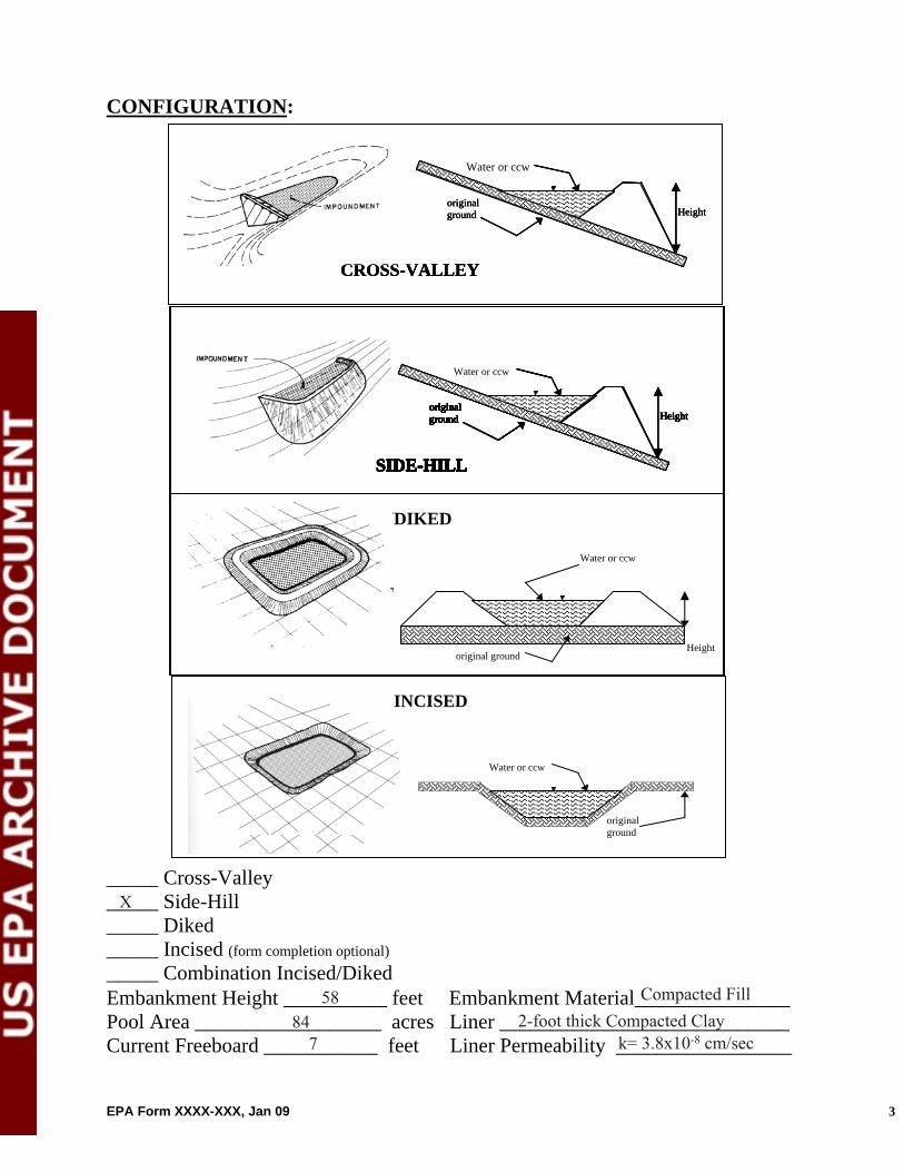
CONFIGURATION:
Height original ground
CROSS-VALLEY
Height original ground
SIDE-HILL
Water or ccw
DIKED
original ground Height
Height original ground
CROSS-VALLEY
Water or ccw
original ground
SIDE-HILL
Height
original
ground
CROSS-VALLEY
original ground
SIDE-HILL
original ground
SIDE-HILL
original ground
SIDE-HILL
original original ground ground
SIDE-HILLSIDE-HILL
original ground
SIDE-HILLSIDE-HILL
original ground Height
SIDE-HILLSIDE-HILLSIDE-HILL
Height Height original ground original ground Height
SIDE-HILL
original ground Height
SIDE-HILL
Water or ccw
original ground Height
SIDE-HILL
INCISED
Water or ccw
original ground
_____ Cross-Valley _____ Side-Hill _____ Diked _____ Incised (form completion optional) _____ Combination Incised/Diked Embankment Height __________ feet Embankment Material_______________Pool Area __________________ acres Liner ____________________________ Current Freeboard ___________ feet Liner Permeability _________________
EPA Form XXXX-XXX, Jan 09 3
Compacted Fill2-foot thick Compacted Clay
k= 3.8x10⁻⁸ cm/sec
X
5884
7

TYPE OF OUTLET (Mark all that apply)
TRAPEZOIDAL
Avg Depth
Bottom Width
Depth
TRIANGULAR _____ Open Channel Spillway _____ Trapezoidal Top Width Top Width
_____ Triangular
RECTANGULAR IRREGULAR
Depth _____ Rectangular _____ Irregular _____ depth _____ bottom (or average) width
Width
Depth
Average Width
_____ top width
_____ Outlet _____ inside diameter
Material Inside Diameter
_____ corrugated metal _____ welded steel _____ concrete _____ plastic (hdpe, pvc, etc.) _____ other (specify) ____________________
Is water flowing through the outlet? YES _______ NO _______ _____ No Outlet
_____ Other Type of Outlet (specify) ________________________________ The Impoundment was Designed By ____________________________________ __________________________________________________________________
EPA Form XXXX-XXX, Jan 09 4
Bechtel Power Corporation
X

Has there ever been a failure at this site? YES __________ NO ___________ If So When? ___________________________ If So Please Describe : _____________________________________________ __________________________________________________________________ __________________________________________________________________ __________________________________________________________________ __________________________________________________________________ __________________________________________________________________ __________________________________________________________________ __________________________________________________________________ __________________________________________________________________ __________________________________________________________________ __________________________________________________________________ __________________________________________________________________ __________________________________________________________________ __________________________________________________________________ __________________________________________________________________ __________________________________________________________________ __________________________________________________________________ __________________________________________________________________ __________________________________________________________________ __________________________________________________________________ __________________________________________________________________ __________________________________________________________________ __________________________________________________________________ __________________________________________________________________ __________________________________________________________________ __________________________________________________________________ __________________________________________________________________ __________________________________________________________________ __________________________________________________________________ __________________________________________________________________ __________________________________________________________________ __________________________________________________________________ __________________________________________________________________
EPA Form XXXX-XXX, Jan 09 5
X

Has there ever been significant seepages at this site? YES _______ NO _______ If So When? ___________________________ IF So Please Describe: _______________________________________________ __________________________________________________________________ __________________________________________________________________ __________________________________________________________________ __________________________________________________________________ __________________________________________________________________ __________________________________________________________________ __________________________________________________________________ __________________________________________________________________ __________________________________________________________________ __________________________________________________________________ __________________________________________________________________ __________________________________________________________________ __________________________________________________________________ __________________________________________________________________ __________________________________________________________________ __________________________________________________________________ __________________________________________________________________ __________________________________________________________________ __________________________________________________________________ __________________________________________________________________ __________________________________________________________________ __________________________________________________________________ __________________________________________________________________ __________________________________________________________________ __________________________________________________________________ __________________________________________________________________ __________________________________________________________________ __________________________________________________________________ __________________________________________________________________ __________________________________________________________________ __________________________________________________________________ __________________________________________________________________
EPA Form XXXX-XXX, Jan 09 6
X

Has there ever been any measures undertaken to monitor/lowerPhreatic water table levels based on past seepages or breaches at this site? YES ________NO ________ If so, which method (e.g., piezometers, gw pumping,...)? ____________________ If so Please Describe : ____________________________________________ __________________________________________________________________ __________________________________________________________________ __________________________________________________________________ __________________________________________________________________ __________________________________________________________________ __________________________________________________________________ __________________________________________________________________ __________________________________________________________________ __________________________________________________________________ __________________________________________________________________ __________________________________________________________________ __________________________________________________________________ __________________________________________________________________ __________________________________________________________________ __________________________________________________________________ __________________________________________________________________ __________________________________________________________________ __________________________________________________________________ __________________________________________________________________ __________________________________________________________________ __________________________________________________________________ __________________________________________________________________ __________________________________________________________________ __________________________________________________________________ __________________________________________________________________ __________________________________________________________________ __________________________________________________________________ __________________________________________________________________ __________________________________________________________________ __________________________________________________________________ __________________________________________________________________ __________________________________________________________________
EPA Form XXXX-XXX, Jan 09 7
X

Appendix B Photographs

A
CDM Project No.: 77646.1801.035.SIT.FAYET
Lower Colorado River Authority Fayette Power Project Station
La Grange, TX
June 23 and 24, 2010
Photo No. 1: Reclaim Pond – Overview of waste drain trench outlet at the north embankment
interior slope.
Photo No. 2: Reclaim Pond – North embankment exterior slope, looking east.
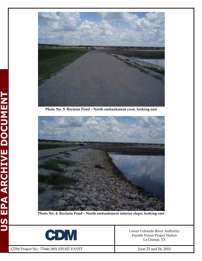
A
CDM Project No.: 77646.1801.035.SIT.FAYET
Lower Colorado River Authority Fayette Power Project Station
La Grange, TX
June 23 and 24, 2010
Photo No. 3: Reclaim Pond – North embankment crest, looking east
Photo No. 4: Reclaim Pond – North embankment interior slope, looking east
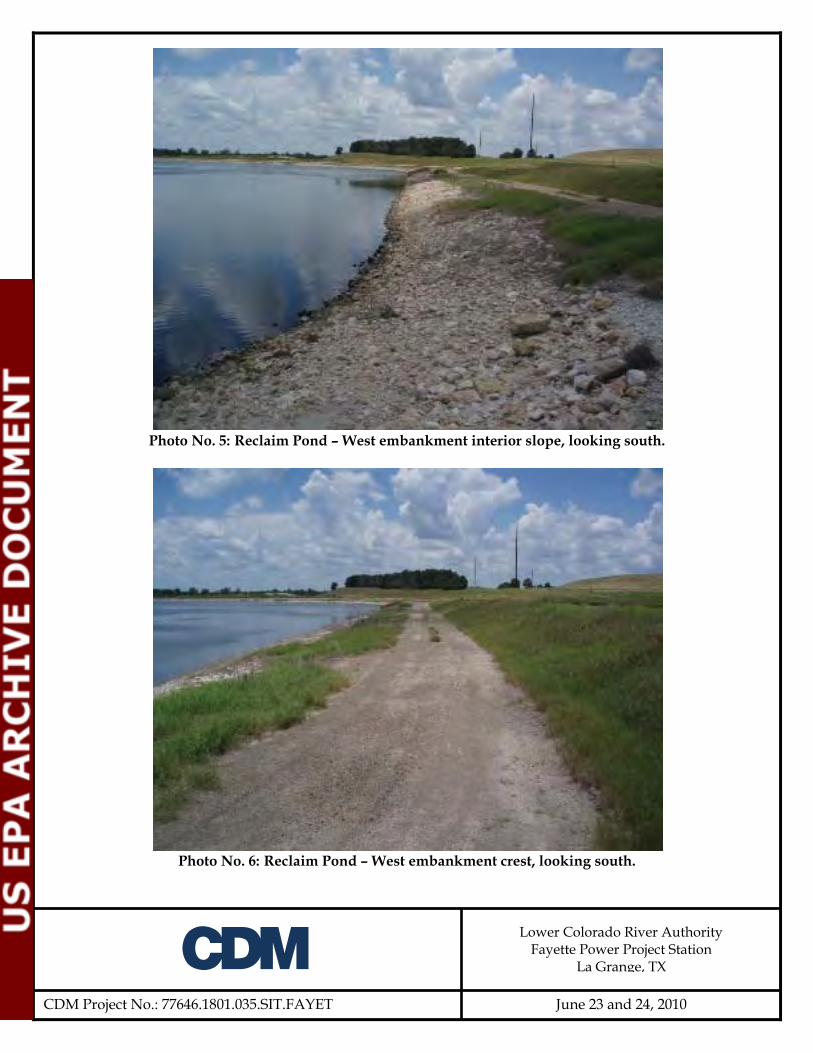
A
CDM Project No.: 77646.1801.035.SIT.FAYET
Lower Colorado River Authority Fayette Power Project Station
La Grange, TX
June 23 and 24, 2010
Photo No. 5: Reclaim Pond – West embankment interior slope, looking south.
Photo No. 6: Reclaim Pond – West embankment crest, looking south.

A
CDM Project No.: 77646.1801.035.SIT.FAYET
Lower Colorado River Authority Fayette Power Project Station
La Grange, TX
June 23 and 24, 2010
Photo No. 7: Reclaim Pond – Overview of west embankment from railroad spur, looking
south.
Photo No. 8: Reclaim Pond – West embankment, looking south at typical bare spots and
tractor ruts on crest and interior slope.
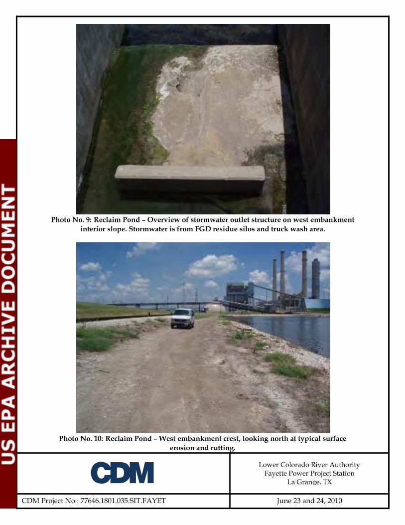
A
CDM Project No.: 77646.1801.035.SIT.FAYET
Lower Colorado River Authority Fayette Power Project Station
La Grange, TX
June 23 and 24, 2010
Photo No. 9: Reclaim Pond – Overview of stormwater outlet structure on west embankment
interior slope. Stormwater is from FGD residue silos and truck wash area.
Photo No. 10: Reclaim Pond – West embankment crest, looking north at typical surface
erosion and rutting.

A
CDM Project No.: 77646.1801.035.SIT.FAYET
Lower Colorado River Authority Fayette Power Project Station
La Grange, TX
June 23 and 24, 2010
Photo No. 11: Reclaim Pond – West embankment interior slope, looking north.
Photo No. 12: Reclaim Pond – South embankment interior slope, looking southeast

A
CDM Project No.: 77646.1801.035.SIT.FAYET
Lower Colorado River Authority Fayette Power Project Station
La Grange, TX
June 23 and 24, 2010
Photo No. 13: Reclaim Pond – Overview of western portion of impoundment, looking north.
Photo No. 14: Reclaim Pond – Overview of impoundment, looking northeast.

A
CDM Project No.: 77646.1801.035.SIT.FAYET
Lower Colorado River Authority Fayette Power Project Station
La Grange, TX
June 23 and 24, 2010
Photo No. 15: Reclaim Pond – Overview of south embankment, looking southeast.
Photo No. 16: Reclaim Pond – South embankment, looking northwest at a low area on the
crest
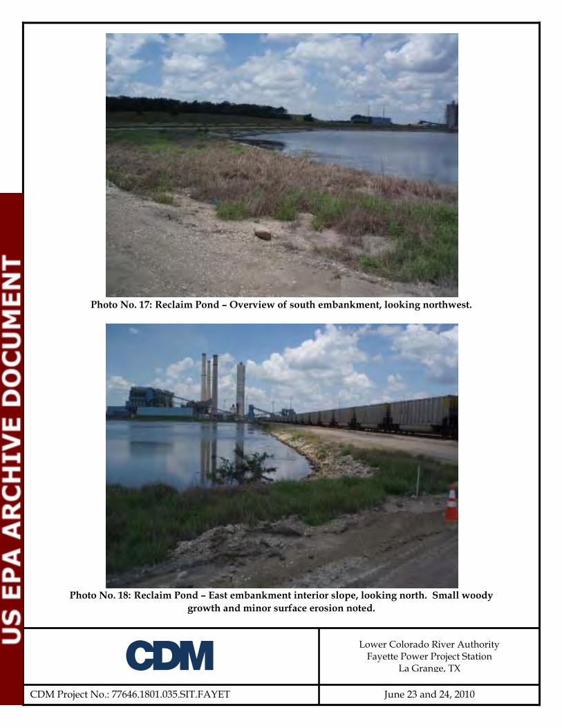
A
CDM Project No.: 77646.1801.035.SIT.FAYET
Lower Colorado River Authority Fayette Power Project Station
La Grange, TX
June 23 and 24, 2010
Photo No. 17: Reclaim Pond – Overview of south embankment, looking northwest.
Photo No. 18: Reclaim Pond – East embankment interior slope, looking north. Small woody
growth and minor surface erosion noted.

A
CDM Project No.: 77646.1801.035.SIT.FAYET
Lower Colorado River Authority Fayette Power Project Station
La Grange, TX
June 23 and 24, 2010
Photo No. 19: Reclaim Pond – East embankment interior slope, looking at a 4-inch-diameter
mesquite tree and brush. Note some minor surface erosion near crest.
Photo No. 20: Reclaim Pond – East embankment interior slope, looking south at rutting and
surface erosion. Note some riprap is missing and displaced.

A
CDM Project No.: 77646.1801.035.SIT.FAYET
Lower Colorado River Authority Fayette Power Project Station
La Grange, TX
June 23 and 24, 2010
Photo No. 21: Reclaim Pond – East embankment interior slope, looking at abandoned 12-
inch-diameter HDPE discharge pipe from the CADP. Note the embankment has been eroded at the discharge pipe.
Photo No. 22: Reclaim Pond – East embankment interior slope, looking at 2.5’W erosion rill.
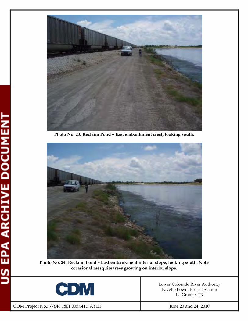
A
CDM Project No.: 77646.1801.035.SIT.FAYET
Lower Colorado River Authority Fayette Power Project Station
La Grange, TX
June 23 and 24, 2010
Photo No. 23: Reclaim Pond – East embankment crest, looking south.
Photo No. 24: Reclaim Pond – East embankment interior slope, looking south. Note
occasional mesquite trees growing on interior slope.

A
CDM Project No.: 77646.1801.035.SIT.FAYET
Lower Colorado River Authority Fayette Power Project Station
La Grange, TX
June 23 and 24, 2010
Photo No. 25: Reclaim Pond – North embankment interior slope, looking west.
Photo No. 26: Reclaim Pond – North embankment crest, looking west.

A
CDM Project No.: 77646.1801.035.SIT.FAYET
Lower Colorado River Authority Fayette Power Project Station
La Grange, TX
June 23 and 24, 2010
Photo No. 27: Reclaim Pond – North embankment exterior slope, looking west.
Photo No. 28: Reclaim Pond – North embankment, looking at emergency spillway channel
entrance.
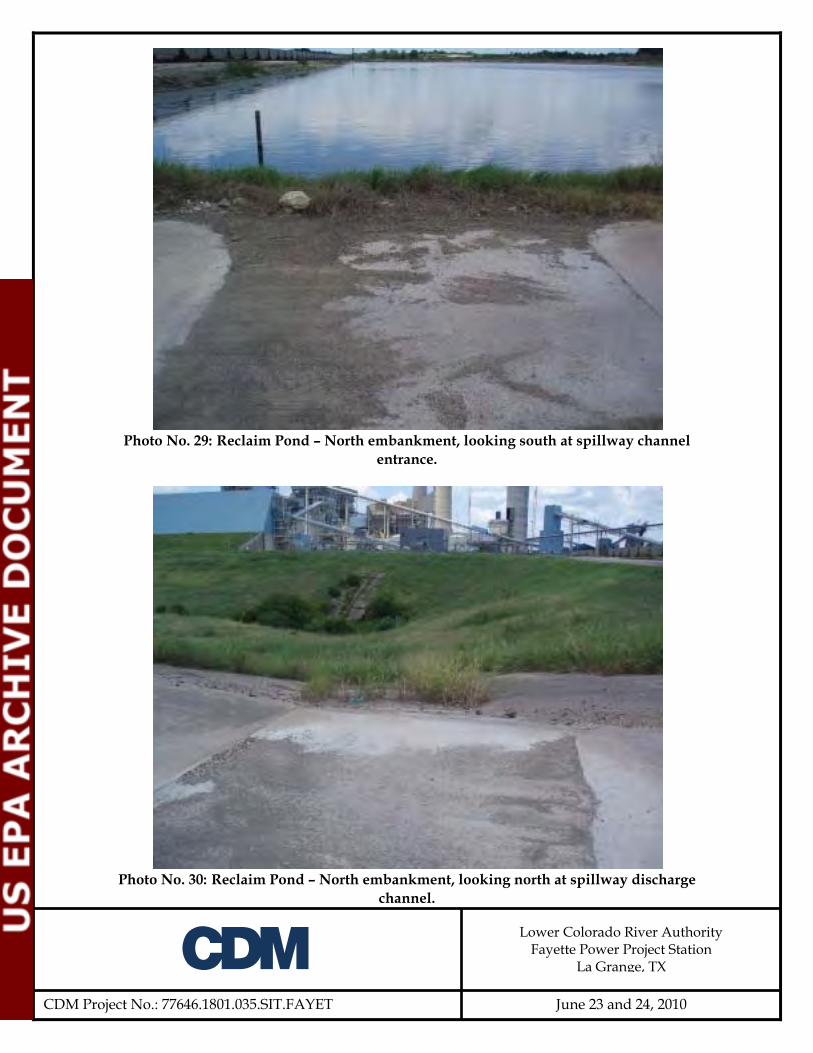
A
CDM Project No.: 77646.1801.035.SIT.FAYET
Lower Colorado River Authority Fayette Power Project Station
La Grange, TX
June 23 and 24, 2010
Photo No. 29: Reclaim Pond – North embankment, looking south at spillway channel
entrance.
Photo No. 30: Reclaim Pond – North embankment, looking north at spillway discharge
channel.

A
CDM Project No.: 77646.1801.035.SIT.FAYET
Lower Colorado River Authority Fayette Power Project Station
La Grange, TX
June 23 and 24, 2010
Photo No. 31: Reclaim Pond – North embankment exterior slope, looking south at spillway
discharge channel.
Photo No. 32: Reclaim Pond – North embankment exterior slope, looking at typical
desiccation cracks.

A
CDM Project No.: 77646.1801.035.SIT.FAYET
Lower Colorado River Authority Fayette Power Project Station
La Grange, TX
June 23 and 24, 2010
Photo No. 33: Reclaim Pond – North embankment interior slope, looking at staff gage at
reclaim pump station
Photo No. 34: Reclaim Pond – North embankment exterior slope, looking east.
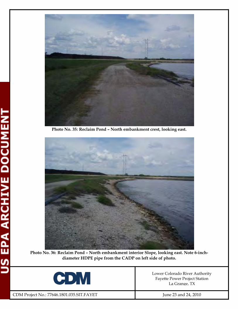
A
CDM Project No.: 77646.1801.035.SIT.FAYET
Lower Colorado River Authority Fayette Power Project Station
La Grange, TX
June 23 and 24, 2010
Photo No. 35: Reclaim Pond – North embankment crest, looking east.
Photo No. 36: Reclaim Pond – North embankment interior Slope, looking east. Note 6-inch-
diameter HDPE pipe from the CADP on left side of photo.

A
CDM Project No.: 77646.1801.035.SIT.FAYET
Lower Colorado River Authority Fayette Power Project Station
La Grange, TX
June 23 and 24, 2010
Photo No. 37: Reclaim Pond – North embankment exterior slope, looking north at two 8-foot-
diameter drainage pipes at toe of slope.
Photo No. 38: Reclaim Pond – Overview of north embankment exterior slope and
downstream area, looking east. Note small trees and brush at the bottom of the slope growing in the drainage ditch.

A
CDM Project No.: 77646.1801.035.SIT.FAYET
Lower Colorado River Authority Fayette Power Project Station
La Grange, TX
June 23 and 24, 2010
Photo No. 39: Reclaim Pond – Overview of north embankment downstream area, looking
north.
Photo No. 40: Reclaim Pond – Overview of north embankment exterior slope and
downstream area, looking west

A
CDM Project No.: 77646.1801.035.SIT.FAYET
Lower Colorado River Authority Fayette Power Project Station
La Grange, TX
June 23 and 24, 2010
Photo No. 41: Reclaim Pond – Overview of north embankment spillway and railroad
embankment, looking south. Note small trees growing at the toe in the drainage ditch.
Photo No. 42: Reclaim Pond – Overview of triple arch culverts under railroad embankment.
Note small trees and vegetation in the drainage ditch and debris in the arch culverts.
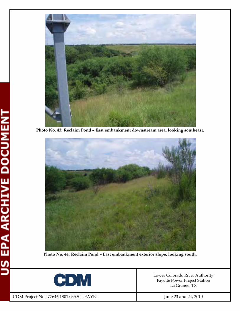
A
CDM Project No.: 77646.1801.035.SIT.FAYET
Lower Colorado River Authority Fayette Power Project Station
La Grange, TX
June 23 and 24, 2010
Photo No. 43: Reclaim Pond – East embankment downstream area, looking southeast.
Photo No. 44: Reclaim Pond – East embankment exterior slope, looking south.
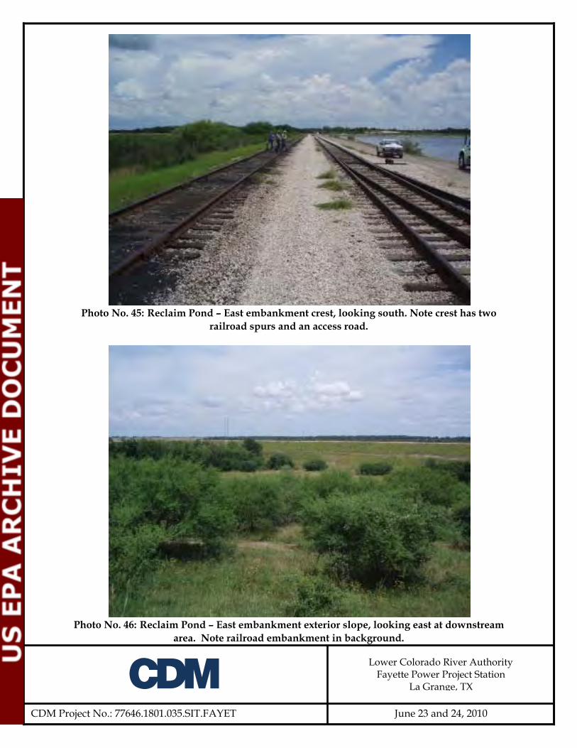
A
CDM Project No.: 77646.1801.035.SIT.FAYET
Lower Colorado River Authority Fayette Power Project Station
La Grange, TX
June 23 and 24, 2010
Photo No. 45: Reclaim Pond – East embankment crest, looking south. Note crest has two
railroad spurs and an access road.
Photo No. 46: Reclaim Pond – East embankment exterior slope, looking east at downstream
area. Note railroad embankment in background.

A
CDM Project No.: 77646.1801.035.SIT.FAYET
Lower Colorado River Authority Fayette Power Project Station
La Grange, TX
June 23 and 24, 2010
Photo No. 47: Reclaim Pond – East embankment exterior slope, looking south.
Photo No. 48: Reclaim Pond – East embankment exterior slope, looking north.

A
CDM Project No.: 77646.1801.035.SIT.FAYET
Lower Colorado River Authority Fayette Power Project Station
La Grange, TX
June 23 and 24, 2010
Photo No. 49: Reclaim Pond – East embankment crest, looking north.
Photo No. 50: Reclaim Pond – East embankment exterior slope, looking north. Note access
road to monitoring wells.

A
CDM Project No.: 77646.1801.035.SIT.FAYET
Lower Colorado River Authority Fayette Power Project Station
La Grange, TX
June 23 and 24, 2010
Photo No. 51: Reclaim Pond – Overview of east embankment downstream area. Note railroad
embankment to the right side of photo.
Photo No. 52: CADP – Overview of final settling basin, looking southeast. Note evaporation
spray system on the right.

A
CDM Project No.: 77646.1801.035.SIT.FAYET
Lower Colorado River Authority Fayette Power Project Station
La Grange, TX
June 23 and 24, 2010
Photo No. 53: CADP – Overview of active portion of impoundment, looking southwest.
Photo No. 54: CADP – Overview of east embankment and downstream area, looking south.

A
CDM Project No.: 77646.1801.035.SIT.FAYET
Lower Colorado River Authority Fayette Power Project Station
La Grange, TX
June 23 and 24, 2010
Photo No. 55: CADP – Overview of east embankment downstream area, looking southeast.
Photo No. 56: CADP – East embankment crest, looking south. Note the fence has been
pushed over from raising the crest 2 feet.

A
CDM Project No.: 77646.1801.035.SIT.FAYET
Lower Colorado River Authority Fayette Power Project Station
La Grange, TX
June 23 and 24, 2010
Photo No. 57: CADP – East embankment exterior slope, looking south.
Photo No. 58: CADP – East embankment exterior slope, looking southeast at groin with
Cedar Creek Dam.

A
CDM Project No.: 77646.1801.035.SIT.FAYET
Lower Colorado River Authority Fayette Power Project Station
La Grange, TX
June 23 and 24, 2010
Photo No. 59: CADP – East embankment interior slope, looking southwest.
Photo No. 60: CADP – East embankment exterior slope looking southwest.
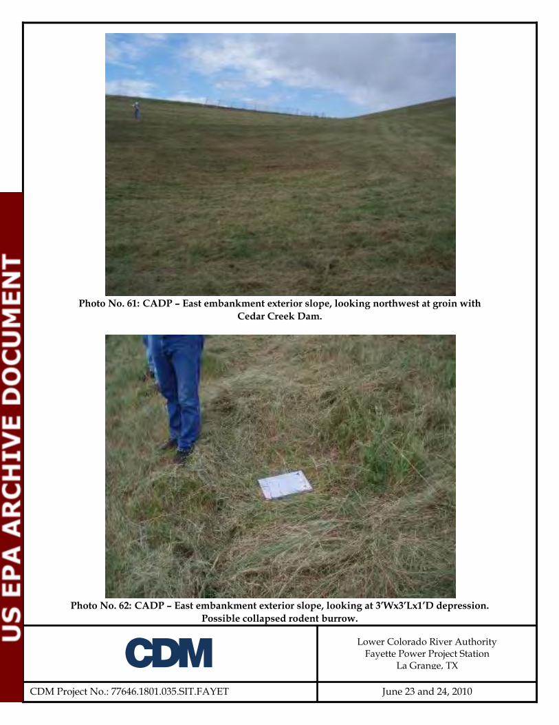
A
CDM Project No.: 77646.1801.035.SIT.FAYET
Lower Colorado River Authority Fayette Power Project Station
La Grange, TX
June 23 and 24, 2010
Photo No. 61: CADP – East embankment exterior slope, looking northwest at groin with
Cedar Creek Dam.
Photo No. 62: CADP – East embankment exterior slope, looking at 3’Wx3’Lx1’D depression.
Possible collapsed rodent burrow.

A
CDM Project No.: 77646.1801.035.SIT.FAYET
Lower Colorado River Authority Fayette Power Project Station
La Grange, TX
June 23 and 24, 2010
Photo No. 63: CADP – East embankment exterior slope, looking at a 6-inch-diameter rodent
hole.
Photo No. 64: CADP – East embankment exterior slope, looking at toe drain outlet.

A
CDM Project No.: 77646.1801.035.SIT.FAYET
Lower Colorado River Authority Fayette Power Project Station
La Grange, TX
June 23 and 24, 2010
Photo No. 65: CADP – East embankment exterior slope, looking at an 8-inch-diameter rodent
hole.
Photo No. 66: CADP – East embankment exterior slope, looking at toe drain seepage
collection sump pit. Seepage water from the toe drain is pumped back to the impoundment.
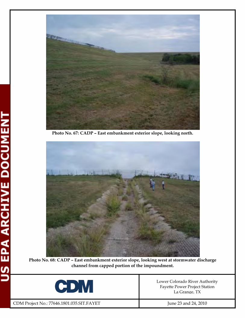
A
CDM Project No.: 77646.1801.035.SIT.FAYET
Lower Colorado River Authority Fayette Power Project Station
La Grange, TX
June 23 and 24, 2010
Photo No. 67: CADP – East embankment exterior slope, looking north.
Photo No. 68: CADP – East embankment exterior slope, looking west at stormwater discharge
channel from capped portion of the impoundment.
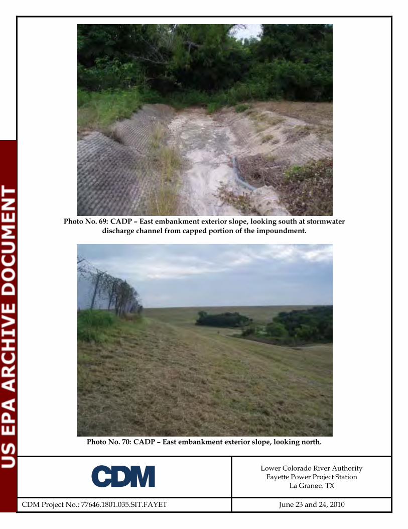
A
CDM Project No.: 77646.1801.035.SIT.FAYET
Lower Colorado River Authority Fayette Power Project Station
La Grange, TX
June 23 and 24, 2010
Photo No. 69: CADP – East embankment exterior slope, looking south at stormwater
discharge channel from capped portion of the impoundment.
Photo No. 70: CADP – East embankment exterior slope, looking north.
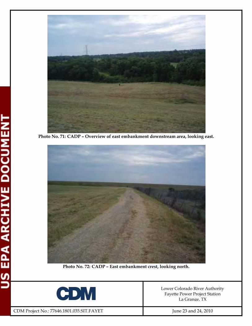
A
CDM Project No.: 77646.1801.035.SIT.FAYET
Lower Colorado River Authority Fayette Power Project Station
La Grange, TX
June 23 and 24, 2010
Photo No. 71: CADP – Overview of east embankment downstream area, looking east.
Photo No. 72: CADP – East embankment crest, looking north.

A
CDM Project No.: 77646.1801.035.SIT.FAYET
Lower Colorado River Authority Fayette Power Project Station
La Grange, TX
June 23 and 24, 2010
Photo No. 73: CADP - East embankment, looking south at approach to discharge channel
inlet control section from capped portion of the impoundment.
Photo No. 74: CADP - East embankment, looking south at stormwater control section outlet
from capped portion of the impoundment.

A
CDM Project No.: 77646.1801.035.SIT.FAYET
Lower Colorado River Authority Fayette Power Project Station
La Grange, TX
June 23 and 24, 2010
Photo No. 75: CADP – South embankment crest and capped area, looking west.
Photo No. 76: CADP – Groin of south embankment exterior slope and Coal Pile Run-off
Pond interior slope, looking west. Note water, brush and small trees at toe of slope.

A
CDM Project No.: 77646.1801.035.SIT.FAYET
Lower Colorado River Authority Fayette Power Project Station
La Grange, TX
June 23 and 24, 2010
Photo No. 77: CADP – South embankment exterior slope, looking east at groin with Coal Pile
Run-off Pond. Note water, brush and small trees at toe of slope.
Photo No. 78: CADP – South embankment exterior slope, looking west.
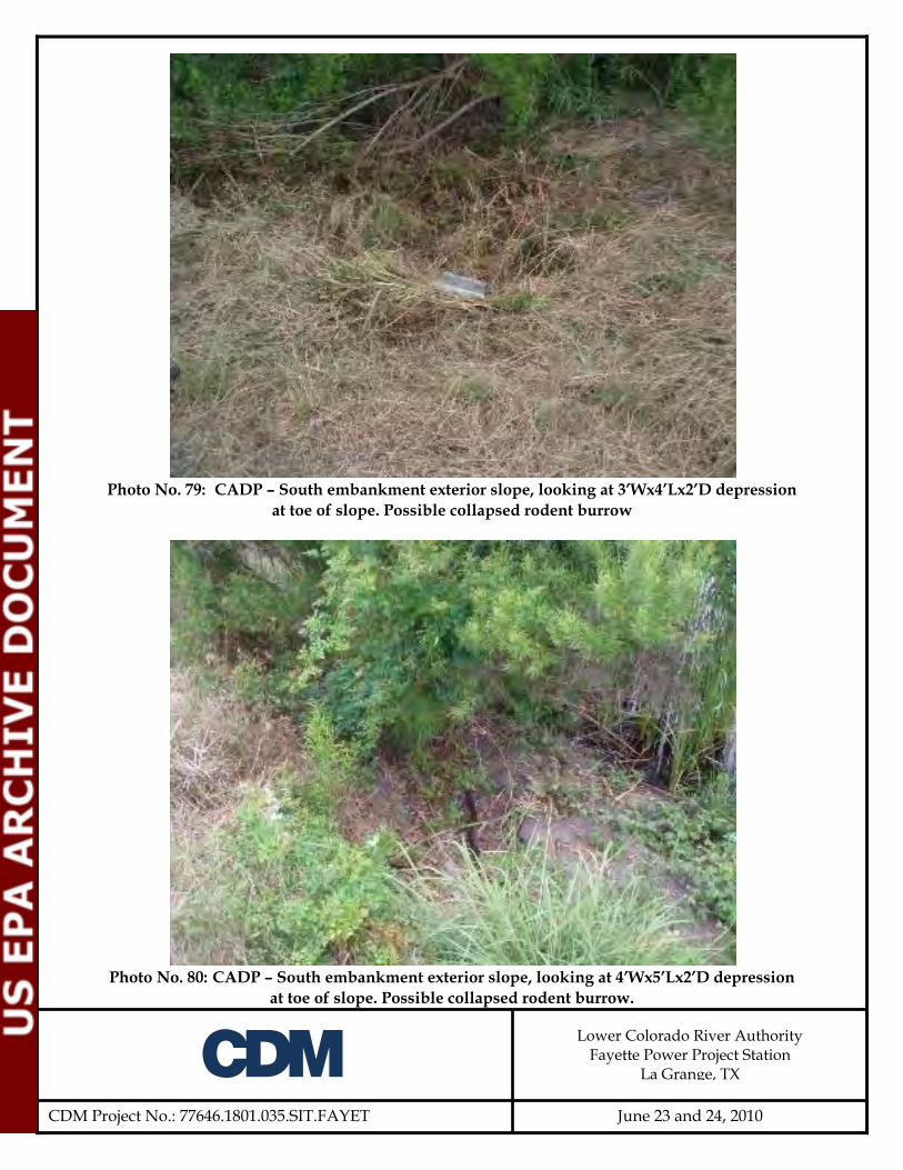
A
CDM Project No.: 77646.1801.035.SIT.FAYET
Lower Colorado River Authority Fayette Power Project Station
La Grange, TX
June 23 and 24, 2010
Photo No. 79: CADP – South embankment exterior slope, looking at 3’Wx4’Lx2’D depression
at toe of slope. Possible collapsed rodent burrow
Photo No. 80: CADP – South embankment exterior slope, looking at 4’Wx5’Lx2’D depression
at toe of slope. Possible collapsed rodent burrow.

A
CDM Project No.: 77646.1801.035.SIT.FAYET
Lower Colorado River Authority Fayette Power Project Station
La Grange, TX
June 23 and 24, 2010
Photo No. 81: CADP – South embankment exterior slope, looking west. Note sparse
vegetation near crest.
Photo No. 82: CADP – South embankment exterior slope, looking at seep containment
system.

A
CDM Project No.: 77646.1801.035.SIT.FAYET
Lower Colorado River Authority Fayette Power Project Station
La Grange, TX
June 23 and 24, 2010
Photo No. 83: CADP – South embankment exterior slope, looking at seep. Note liner down
slope of seep to collect water. Flow ~8 gallons per day.
Photo No. 84: CADP – South embankment exterior slope, looking at 2’Wx4’Lx1’D depression
at toe of slope. Possible collapsed rodent burrow.

A
CDM Project No.: 77646.1801.035.SIT.FAYET
Lower Colorado River Authority Fayette Power Project Station
La Grange, TX
June 23 and 24, 2010
Photo No. 85: CADP – South embankment exterior slope, looking east.
Photo No. 86: CADP – South embankment crest, looking east.

A
CDM Project No.: 77646.1801.035.SIT.FAYET
Lower Colorado River Authority Fayette Power Project Station
La Grange, TX
June 23 and 24, 2010
Photo No. 87: CADP – South embankment, looking east at capped portion of impoundment.
Photo No. 88: CADP – Overview of capped area, looking northeast from southwest corner of
impoundment.

A
CDM Project No.: 77646.1801.035.SIT.FAYET
Lower Colorado River Authority Fayette Power Project Station
La Grange, TX
June 23 and 24, 2010
Photo No. 89: CADP – West embankment crest, looking north.
Photo No. 90: CADP – overview of transition between the active and the capped portion of
the impoundment, looking east.

A
CDM Project No.: 77646.1801.035.SIT.FAYET
Lower Colorado River Authority Fayette Power Project Station
La Grange, TX
June 23 and 24, 2010
Photo No. 91: CADP – Overview of the active portion of the impoundment, looking
northeast.
Photo No. 92: CADP – West embankment interior slope, looking at staff gage on intake
structure.

A
CDM Project No.: 77646.1801.035.SIT.FAYET
Lower Colorado River Authority Fayette Power Project Station
La Grange, TX
June 23 and 24, 2010
Photo No. 93: CADP – West embankment interior slope, close up of staff gage on intake
structure.
Photo No. 94: CADP – Overview of final settling basin area, looking northeast.

A
CDM Project No.: 77646.1801.035.SIT.FAYET
Lower Colorado River Authority Fayette Power Project Station
La Grange, TX
June 23 and 24, 2010
Photo No. 95: CADP – Overview of two primary settling basins where CCW is sluiced into
the impoundment. Settling basins are alternated and cleaned out when full.
Photo No. 96: CADP – West embankment interior slope, looking south.

A
CDM Project No.: 77646.1801.035.SIT.FAYET
Lower Colorado River Authority Fayette Power Project Station
La Grange, TX
June 23 and 24, 2010
Photo No. 97: CADP – Overview of active portion of impoundment, looking southeast.
Photo No. 98: CADP – North embankment interior slope, looking east. Note Cedar Creek
Dam on left side of photo.

A
CDM Project No.: 77646.1801.035.SIT.FAYET
Lower Colorado River Authority Fayette Power Project Station
La Grange, TX
June 23 and 24, 2010
Photo No. 99: CADP – North embankment crest, looking at tension crack in road base fill.
Photo No. 100: CADP – North embankment crest, looking east. Note trees growing inside the
fence limits. Trees are in the area of the toe of the Cedar Creek Dam.

A
CDM Project No.: 77646.1801.035.SIT.FAYET
Lower Colorado River Authority Fayette Power Project Station
La Grange, TX
June 23 and 24, 2010
Photo No. 101: CADP – North embankment crest, looking west.
Photo No. 102: CADP – East embankment crest, looking north.

A
CDM Project No.: 77646.1801.035.SIT.FAYET
Lower Colorado River Authority Fayette Power Project Station
La Grange, TX
June 23 and 24, 2010
Photo No. 103: CADP – Looking west at transition from active portion to capped portion of
impoundment from east embankment crest.
Photo No. 104: CADP – East embankment crest, looking south.

A
CDM Project No.: 77646.1801.035.SIT.FAYET
Lower Colorado River Authority Fayette Power Project Station
La Grange, TX
June 23 and 24, 2010
Photo No. 105: CADP – Overview of capped portion of impoundment from northeast corner,
looking southwest.

Appendix C Photo GPS Locations

Photo No. Northing Easting1 13,885,629 2,680,6502 13,885,680 2,680,3663 13,885,639 2,680,3714 and 5 13,885,608 2,680,3746 13,885,598 2,680,3467 13,885,590 2,680,3178 13,885,411 2,680,3449 13,885,136 2,680,35310, 11, and 12 13,884,901 2,680,35513, 14, and 15 13,884,631 2,680,35516 13,884,466 2,680,61717 and 18 13,884,186 2,681,369no photo 13,884,218 2,681,40619 13,884,636 2,681,39720 13,885,275 2,681,39821 and 22 13,885,541 2,681,39323, 24, and 25 13,885,706 2,681,39726 and 27 13,885,768 2,681,35728 13,885,719 2,681,33129 and 30 13,885,732 2,681,31131 13,885,791 2,681,29332 13,885,753 2,680,86533 13,885,662 2,680,80634, 35, 36, and 37 13,885,675 2,680,77438 and 39 13,885,715 2,680,65540 13,885,710 2,680,61641 13,886,140 2,681,20442 13,886,074 2,681,16943 13,885,756 2,681,45044 13,885,680 2,681,47245 13,885,666 2,681,43846 and 47 13,885,142 2,681,45648 13,884,807 2,681,53849, 50, and 51 13,884,295 2,681,45452 13,887,869 2,683,43553, 54, and 55 13,887,351 2,685,61056, 57, 58, and 59 13,887,209 2,685,33360 and 61 13,886,965 2,685,53062 13,886,649 2,685,42963 13,886,552 2,685,44464 13,886,502 2,685,53065 13,886,481 2,685,52666 13,886,238 2,685,46167 13,885,627 2,685,125
Datum: NAD 1983 (Consus)Coordinate Units: Feet
Appendix CPhoto GPS Locations
Site: Fayette Power ProjectSystem: US State Plane 1983Zone:Texas South Central 4204

Photo No. Northing Easting
Datum: NAD 1983 (Consus)Coordinate Units: Feet
Appendix CPhoto GPS Locations
Site: Fayette Power ProjectSystem: US State Plane 1983Zone:Texas South Central 4204
68 and 69 13,885,570 2,684,99770 and 71 13,885,767 2,685,00172 13,885,800 2,684,98973 13,885,786 2,684,91174 13,885,750 2,684,92175 13,885,720 2,684,83276 13,885,700 2,684,76477 and 78 13,885,786 2,684,38279 13,885,838 2,684,13080 13,885,918 2,683,78881 13,885,978 2,683,66382 13,886,046 2,683,37583 13,886,013 2,683,34284 13,886,040 2,683,24785 13,886,097 2,683,05386 13,886,121 2,683,06187 13,886,140 2,683,05388 13,886,129 2,682,95389 13,886,148 2,682,99190 and 91 13,886,850 2,682,95092 and 93 13,886,989 2,683,15094 13,886,987 2,683,11595 13,886,821 2,683,93096, 97, and 98 13,887,883 2,683,14499 13,887,720 2,683,535100 13,887,601 2,684,064101 13,887,283 2,685,299102, 103, 104, and 105 13,886,450 2,685,305