ata6870n - farnell
TRANSCRIPT

ATA6870N
Li-Ion, NiMH Battery Measuring, Charge Balancing andPower-supply Circuit
DATASHEET
Features
● 12-bit battery-cell voltage measurement
● Simultaneous battery cells measurement in parallel
● Cell temperature measurement
● Charge Balancing Capability
● Parallel balancing of cells possible
● Integrated power supply for MCU
● Undervoltage detection
● Less than 10µA standby current
● Low cell imbalance current (< 10µA)
● Hot plug-in capable
● Interrupt timer for cycling MCU wake-ups
● Cost-efficient solution due to cost-optimized 30V CMOS technology
● Reliable communication between stacked ICs due to level shifters with current
sources and checksum monitoring of data
● Daisy-chainable
● Each IC monitors up to 6 battery cells● 16 ICs (96 cells) per string● No limit on number of strings
● Package QFN48 7mm ×7mm
Applications
● Battery measurement, supply and monitoring IC for Li-ion and NiMH battery
systems in Electric (EV) and Hybrid Electrical (HEV) Vehicles
● Electrical and hybrid electrical vehicles
● Li-Ion batteries as 12V lead-acid battery replacement
● Ebike, scooters
● Uninterruptible power supply (UPS)
● Smart grid
Benefits
● Cost reduction due to integrated measurement circuit and high voltage
power-supply
9317B-AUTO-06/14

1. Description
The Atmel® ATA6870N is a measurement and monitoring circuit designed for Li-ion and NiMH multicell battery stacks in hybrid electrical vehicles.
The Atmel ATA6870N monitors the battery-cell voltage and the battery-cell temperature with a 12-bit ADC.
The circuit also provides charge-balancing capability for each battery-cell.
In addition, a linear regulator is integrated to supply a microcontroller or other external components. Reliable communication between stacked ICs is achieved by level-shifters with current sources. The Atmel ATA6870N can be connected to three, four, five or six battery-cells. Up to 16 circuits (96 cells) can be cascaded in one string. The number of strings is not limited.
2. Block Diagram
Figure 2-1. Block Diagram
IRQCLK
Cell 1:Reference
ADCCell Balancing
Cell 6:Reference
ADCCell Balancing
CellTemperatureMeasuring
MBAT2
TEMPVSS
NTCNTC
AVSSATSTCS_FUSE
SCANMODE MFIRSTDTST VDDFUSE
VDDHV
AVDD
POW_ENA
VDDHVM
VDDHVP
PD_N
PD_N_OUT
TEMP2
MBAT1
MBAT7
MBAT6
DISCH1
DISCH6
SCKMOSIMISO
CS_N
IRQ_INCLK_OUTCS_N_OUTSCK_OUTMOSI_OUTMISO_IN
DVDD
TEMP1
TEMPREF
GND DVSS
Interchipand
MicrocontrollerCommunication
Interface
3.3VVoltage Regulator
3.3V InternalVoltage Regulator
Dig
ital
Leve
l Shi
fter
Test
Logi
c
Dig
ital
Leve
l Shi
fter
Dig
ital
Leve
l Shi
fter
Internal Biasing
To ATA6870below
To ATA6870above
BIASRES
Standby Control
MCU
PWTST
ATA6870N [DATASHEET]9317B–AUTO–06/14
2

3. Pin Configuration
Figure 3-1. Pinning QFN48, 7 mm ×7 mm
Table 3-1. Pin Description
Pad Number Pad Name Function Remark
Exposed Pad Heatslug
1 DISCH5Output to drive external cell-balancing transistor
2 MBAT5 Battery cell sensing line
3 DISCH4Output to drive external cell-balancing transistor
4 MBAT4 Battery cell sensing line
5 DISCH3Output to drive external cell-balancing transistor
6 MBAT3 Battery cell sensing line
7 DISCH2Output to drive external cell-balancing transistor
8 MBAT2 Battery cell sensing line
9 DISCH1Output to drive external cell-balancing transistor
10 MBAT1 Battery cell sensing line
11 IRQ Interrupt output for MCU/ATA6870N below
12 CLK System clock
13 CS_N Chip select input from MCU/ATA6870N below
14 SCK SPI clock input from MCU/ATA6870N below
15 MOSI Master Out Slave In input from MCU SPI data input
AtmelATA6870N
CLK
IRQ
DISCH1
MBAT2DISCH2
MBAT3
DISCH4
DISCH5MBAT5
MBAT4
DISCH3
MBAT1
ATSTAVDD
TEMPVSS
TEMP1TEMP2TEMPREF
POW_ENAPD_N_OUT
PWTSTBIASRES
AVSS
VDDHVM
PD
_NM
ISO
_IN
MO
SI_
OU
TS
CK
_OU
T
CS
_N_O
UT
CLK
_OU
TIR
Q_I
N
VD
DH
VM
BA
T7
DIS
CH
6M
BA
T6
DV
DD
GN
D
DV
SS
VD
DFU
SE
CS
_FU
SE
SC
AN
MO
DE
DTS
TM
FIR
ST
MIS
O
MO
SI
SC
K
CS
_N
373839404142434445464748
24
25
26
27
28
29
30
31
32
33
34
35
36
12
11
10
9
8
7
6
5
4
3
2
1
2322212019181716151413
VD
DH
VP
3ATA6870N [DATASHEET]9317B–AUTO–06/14

16 MISO Master In Slave Out output for MCU SPI data output
17 MFIRST Select Master/Slave
18 DTST Test-mode pin Keep pin open (output)
19 SCANMODE Test-mode pin Connected to VSSA
20 CS_FUSE Test-mode pin Connected to VSSA
21 VDDFUSE Test-mode pin Connected to VSSA
22 DVSS Digital negative supply
23 DVDD Digital positive supply input (3.3V) Connected to AVDD
24 GND Ground
25 ATST Test-mode pin Keep pin open (output)
26 AVDD 3.3V Regulator output
27 AVSS Analog negative supply
28 TEMPVSS Ground for temperature measuring
29 TEMP1 Temperature measuring input 1
30 TEMP2 Temperature measuring input 2
31 TEMPREF Reference voltage for temperature measuring
32 BIASRES Internal supply current adjustment
33 PWTST Test - mode pin Keep pin open (output)
34 POW_ENA Power regulator enable/disable
35 PD_N_OUT Power down output
36 VDDHVMPower regulator output to supply e.g. an external microcontroller
37 VDDHVP Power regulator supply voltage
38 PD_N Power down input
39 MISO_INMaster In Slave Out input from ATA6870N above
40 MOSI_OUTMaster Out Slave In output for ATA6870N above
41 SCK_OUT SPI clock output for input of ATA6870N above
42 CS_N_OUTChip select output for input of ATA6870N above
43 CLK_OUTSystem clock output for input of ATA6870N above
44 IRQ_IN Interrupt input from ATA6870N above
45 VDDHV Supply voltage
46 MBAT7 Battery cell sensing line
47 DISCH6Output to drive external cell-balancing transistor
48 MBAT6 Battery cell sensing line
Table 3-1. Pin Description (Continued)
Pad Number Pad Name Function Remark
ATA6870N [DATASHEET]9317B–AUTO–06/14
4

4. ATA6870N System Overview
The Atmel® ATA6870N can be stacked up to 16 times in one string. The communication with MCU is carried out on the lowest level through an SPI bus. The data on the SPI bus is transmitted to the 15 other Atmel ATA6870Ns using the communication interface implemented inside Atmel ATA6870N.
Figure 4-1. Battery Management Architecture with One Battery String
AtmelATA6870N
MCU
AtmelATA6870N
AtmelATA6870N
AtmelATA6870N
5ATA6870N [DATASHEET]9317B–AUTO–06/14

Figure 4-2. Battery Management Architecture with Several Battery Strings
MCU
MCU
OPTO
To BatteryMaster Controller
AtmelATA6870N
AtmelATA6870N
AtmelATA6870N
AtmelATA6870N
ATA6870N [DATASHEET]9317B–AUTO–06/14
6

5. Absolute Maximum Ratings
Stresses beyond those listed under “Absolute Maximum Ratings” may cause permanent damage to the device. This is a stress rating only and functional operation of the device at these or any other conditions beyond those indicated in the operational sections of this specification is not implied. Exposure to absolute maximum rating conditions for extended periods may affect device reliability.
Unless otherwise specified all voltages to pin VSSA.
Parameters Pin Symbol Min. Max. Unit
Ambient temperature TA –40 +85 °C
Junction temperature TJ –40 +125 °C
Storage temperature TS –55 +150 °C
Battery cell voltageMBAT(i+1),
MBAT(i)VMBAT(i+1) -
VMBAT(i)–0.3 +5.5 V
VVDDHV - VVMBAT7max VVDDHV - VVMBAT7 –5.5 +0.3 V
VMBAT1 MBAT1 VMBAT1 –0.3 +0.3 V
Supply voltage power regulator VDDHVP VVDDHVP –0.3 +33.6 V
Operating supply voltage VDDHV VVDDHV –0.3 +30 V
Supply voltage DVDD (regulator is off) DVDD VDVDD –0.3 +5.5 V
Supply voltage AVDD (regulator is off) AVDD VAVDD –0.3 +5.5 V
Test-input VDDFUSE VVDDFUSE –0.3 +5.5 V
Reference voltage for temperature measuring (regulator is Off)
TEMPREF VTEMPREF –0.3 VDD+0.3 V
Supply voltage VDDHVM (regulator is Off) VDDHVM V VDDHVM –0.3 +5.5 V
Digital ground DVSS VAVSS - VGND –0.3 +0.3 V
Analog ground AVSS VAVSS - VGND –0.3 +0.3 V
Digital/analog ground AVSS, DVSS VAVSS - VDVSS –0.3 +0.3 V
Ground voltage for temperature measuring TEMPVSS VTEMPVSS –0.3 +0.3 V
Input voltage for logic I/O pins
CLK, CS_N, SCK, MOSI, DTST, ATST, SCANMODE,
MFIRST, POW_ENA, CS_FUSE,
PWTST
VCLK, VCS_N, VSCK, VMOSI, VDTST, VATST, VSCANMODE,
VMFIRST, VPOW_ENA, VCS_FUSE, VPWTST
–0.3 VDD + 0.3 V
IRQ, MISO VIRQ, VMISO –0.3 +5.5 V
Input voltage for analog I/O pinsTEMP1, TEMP2,
BIASRES
VTEMP1, VTEMP2, VBIASRES
–0.3 VDD + 0.3 V
Input voltage for digital high voltage input pins
MISO_IN, IRQ_IN
VMISO_IN, VIRQ_IN VDDHV – 0.3 VDDHV + 0.3 V
Voltage at digital high voltage output pins
MOSI_OUT, SCK_OUT,
CS_N_OUT, CLK_OUT
VMOSI_OUT, VSCK_OUT, VCS_N_OUT, VCLK_OUT
VDDHV – 0.3 VDDHV + 0.3 V
Input: PD_N PD_N V PD_N VDDHV – 5.5 VDDHV + 0.3 V
Output: PD_N_OUT PD_N_OUT V PD_N_OUT –5.5 +0.3 V
Voltage at cell balancing outputs DISCH(i) VDISCH(i) VMBAT(i) – 0.3 VMBAT(i+1) + 0.3 V
7ATA6870N [DATASHEET]9317B–AUTO–06/14

7. Circuit Description and Electrical Characteristics
Unless otherwise specified all parameters in this section are valid for a supply voltage range of 6.9V < VDDHV < 30V and a battery cell voltage of VMBAT(i+1) – VMBAT(i) = 0V to 5V, –40°C < TA < 85°C. All values refer to pin VSSA, unless otherwise specified.
7.1 Operating Modes
The Atmel® ATA6870N has two operation modes.
1. Power-down mode (PDmode)
2. Normal mode (NORM mode)
7.1.1 Power-down Mode
In power-down mode all blocks of the IC are switched off.
The circuit can be switched from Power-down to ON mode or back via the PD_N input. If the pin is connected to VDDHV via an external optocoupler, for example, the circuit is in ON mode. If several Atmel ATA6870N are stacked, the power-down signal must be only provided for the IC on the top level of the stack. The next lower IC receives this information from the PD_N_OUT output of its upper IC. The PD_N_OUT pin must be connected to either the PD_N pin of the next lower Atmel ATA6870N or to VSSA.
HBM ESDANSI/ESD-STM5.1JESD22-A114AEC-Q100 (002) ESD
±2 kV
CDM ESD STM 5.3.1
500 V
1, 12, 13, 24, 25, 36, 37, 48
750 V
Latch-up acc. to AECQ100-004, JESD78A LATCH-UP ±100 mA
5. Absolute Maximum Ratings (Continued)
Stresses beyond those listed under “Absolute Maximum Ratings” may cause permanent damage to the device. This is a stress rating only and functional operation of the device at these or any other conditions beyond those indicated in the operational sections of this specification is not implied. Exposure to absolute maximum rating conditions for extended periods may affect device reliability.
Unless otherwise specified all voltages to pin VSSA.
Parameters Pin Symbol Min. Max. Unit
6. Thermal ResistanceParameters Symbol Value Unit
Package. QFN48 7×7
Max. thermal resistance junction-ambient(1) Rthjamax 20 K/W
Max. thermal resistance junction-case RthjCmax TBD K/W
Note: 1. Package mounted on 4 large PCB (per JESD51-7) under natural convention as defined in JESD51-2.
ATA6870N [DATASHEET]9317B–AUTO–06/14
8

Figure 7-1. Power-down
SC
AN
MO
DE
CS
_FU
SE
DTS
T
DV
SS
AVS
S
ATS
T
VD
DFU
SE
GN
D
IRQCLK
Cell 1:Reference
ADCCell Balancing
Cell 6:Reference
ADCCell Balancing
CellTemperatureMeasuring
MBAT2
TEMPVSS
NTCNTC
SC
AN
MO
DE
CS
_FU
SE
DTS
T
DV
SS
AVS
S
ATS
T
MFI
RS
TM
FIR
ST
VD
DFU
SE
VDDHV
AVDD
POW_ENA
VDDHVM
VDDHVP
PD_N
PD_N_OUT
TEMP2
MBAT1
MBAT7
MBAT6
DISCH1
DISCH6
SCKMOSIMISO
CS_N
IRQ_INCLK_OUTCS_N_OUTSCK_OUTMOSI_OUTMISO_IN
DVDD
TEMP1
TEMPREF
Interchipand
MicrocontrollerCommunication
Interface
3.3VVoltage Regulator
3.3V InternalVoltage Regulator
Dig
ital
Leve
l Shi
fter
Test
Logi
c
Dig
ital
Leve
l Shi
fter
Dig
ital
Leve
l Shi
fter
Internal Biasing
ATA6870
ATA6870
BIASRES
Standby Control
GN
D
IRQCLK
Cell 1:Reference
ADCCell Balancing
Cell 6:Reference
ADCCell Balancing
CellTemperatureMeasuring
MBAT2
TEMPVSS
NTCNTC
VDDHV
AVDD
POW_ENA
VDDHVM
VDDHVP
PD_N
PD_N_OUT
TEMP2
MBAT1
MBAT7
MBAT6
DISCH1
DISCH6
SCKMOSIMISO
CS_N
IRQ_INCLK_OUTCS_N_OUTSCK_OUTMOSI_OUTMISO_IN
DVDD
TEMP1
TEMPREF
Interchipand
MicrocontrollerCommunication
Interface
3.3VVoltage Regulator
3.3V InternalVoltage Regulator
Dig
ital
Leve
l Shi
fter
Test
Logi
c
Dig
ital
Leve
l Shi
fter
Dig
ital
Leve
l Shi
fter
Internal Biasing
BIASRES
Standby Control
MCU
PW
TST
PW
TST
9ATA6870N [DATASHEET]9317B–AUTO–06/14

7.1.2 Normal Operating Mode (NORM Mode)
The Atmel® ATA6870N turns on when the PD_N signal is switched from low to high. The power supplies AVDD and DVDD as well as VDDHVM (if the input signal POW_ENA = high) are turned on. The configuration registers are set to their default values. In NORM mode the Atmel ATA6870N can acquire analog data (voltage or temperature channels) upon request from the host microcontroller. When the host microcontroller orders an acquisition through the SPI bus, the IC starts digitizing all voltage and one temperature channel in parallel. The on-chip digital signal processor filters, in real time, the channel samples. When conversion and filtering are done, the data-ready interrupt to the host processor indicates the data availability. The MCU can now read the ADC result registers. The MCU reads the Atmel ATA6870N’s status registers to check each IC and to acknowledge the interrupt. When Atmel ATA6870N is in NORM mode, the MCU can be active or in idle mode. In order to wake-up the MCU by an interrupt, the Low Frequency Timer (LFT) can be activated in Atmel ATA6870N. Interrupt is signaled with a high level on IRQ pin. The LFT is re-programmable on the fly and can be reset through SPI, but is not stoppable.
Figure 7-2. Atmel ATA6870N in NORM Mode
Table 7-1. Electrical Characteristics
No. Parameters Test Conditions Pin Symbol Min. Typ. Max. Unit Type*
1.1
Maximum allowed input current in power-down mode (e.g., leakage current of an optocoupler)
PD_N IPD_N 50 µA A
1.2 Input current in ON mode PD_N IPD_N 2.5 5 mA A
1.3Maximum voltage (pin PD_N left open)
IPD_N = 0 to 50µA PD_NVVDDHV -
VPD_N5 V A
1.4Propagation delay time from power-down mode to NORM mode
min slope
DVDD tVDDON 3 ms A
1.5Propagation delay time from NORM mode to power-down mode
DVDD tVDDOFF 10 ms A
*) Type means: A = 100% tested, B = 100% correlation tested, C = Characterized on samples, D = Design parameter
IPD_N1 mAmsec-------------=
Backgroundtask/Idle
Backgroundtask
Send SPICommand
Backgroundtask
InterruptHandling
Read status registerACQ Cmd
AssertedIdle Idle
AcquisitionASICs in NOMode
MCU
SPI
IRQ
Read data burst mode
Processing
ATA6870N [DATASHEET]9317B–AUTO–06/14
10

7.2 Interface to Battery Cells
Each input line MBAT(i) and the supply lines VDDHV, AVSS can be protected by additional resistors and a filter capacitor as shown below.
Figure 7-3. External Components between Atmel ATA6870N and the Battery Cells
MBAT(i) are high impedance input (~2MΩ). Thus, external components can be added to protect ATA6870N chip against current spikes and overvoltage at battery cell level.
Table 7-2. Electrical Characteristics
No. Parameters Test Conditions Pin Symbol Min. Typ. Max. Unit Type*
2.1 Supply voltage VDDHV VVDDHV 6.9 30 V A
2.2Current consumption IVDDHV (normal mode)
VDDHV IVDDHV 15 mA A
2.3
Current consumption in power-down mode (PDmode) IVDDHV + IMBAT(i)max(1)
VMBAT(i+1) – VMBAT(i) = 3.7V
VDDHV 10 µA A
2.4
Imbalance from battery cell to battery cell in power-down mode (PDN Mode)
VMBAT(i+1) – VMBAT(i) = 3.7V
MBAT(i+1) IMBAT(i+1) 10 µA A
*) Type means: A = 100% tested, B = 100% correlation tested, C = Characterized on samples, D = Design parameter
Note: 1. Largest input current of the cell inputs MBAT(i)
MBAT(i+1)R_IN
R_IN
Batterycell(i)
BoardBattery cell ATA6870
Cell(i)DISCH(i)
AVSS
DischargeResistor
R_VDDHV
R_VSS
VDDHV
MBAT(i)
11ATA6870N [DATASHEET]9317B–AUTO–06/14

7.3 Reduced Number of Battery Cells Configuration
It is possible for Atmel® ATA6870N to operate with a reduced number of cells: 3, 4, 5, and 6 cell operation are possible. In these cases, the cell-chip inputs corresponding to the missing cells should be connected to the upper cell potential of the module.
Figure 7-4. Connection with 4 Cells only
Battery cell 1 (MBAT1, MBAT2) and battery cell 6 (MBAT6, MBAT7) must always be used for the lowest/highest cell.
Table 7-3. Electrical Characteristics
No. Parameters Test Conditions Pin Symbol Min. Typ. Max. Unit Type*
3.1 R_IN MBAT(i) 1 kΩ D
3.2 R_VDDHV VDDHV 50 Ω D
3.3 R_VSS AVSS 50 Ω D
*) Type means: A = 100% tested, B = 100% correlation tested, C = Characterized on samples, D = Design parameter
MBAT6
AtmelATA6870N
DISCH5
MBAT4
MBAT5
DISCH4
POW_ENA
VDDHVP
VDDHVM
CS_N_OUT
CLK_OUT
SCK_OUT
MOSI_OUT
IRQ
PD_N_OUT
PD_N
CLK
CS_N
SCK
MOSI
MISO
IRQ_IN
MISO_IN
BIASRES
DVDD
AVDD
MBAT7
DISCH6
DISCH3
MBAT3
MBAT2
DISCH1
MBAT1
GN
D
DISCH2
TEMPREFTEMP2TEMP1TEMPVSS
AVS
SV
DD
HV
DV
SS
DTS
T
CS
_FU
SE
SC
AN
MO
DE
ATS
T
VD
DFU
SE
MFI
RS
T
ATA6870N [DATASHEET]9317B–AUTO–06/14
12

7.4 ATA6870N External MCU Supply
The Atmel® ATA6870N provides a 3.3V power-supply for external components such as the microcontroller unit (MCU). The input pin for this supply is pin VDDHVP, and the output pin is VDDHVM. This regulator is able to supply the MCU directly from the topmost battery cell of a string. The power regulators of all stacked Atmel ATA6870N are therefore put in serial configuration to avoid imbalance.The regulator can be disabled with the digital input pin POW_ENA.
Logic levels: Low = VDVSS, High = VDVDD
Table 7-4. Truth Table
Pin Symbol Value Function
POW_ENA VPOW_ENA
Low Voltage regulator disabled
High Voltage regulator enabled
13ATA6870N [DATASHEET]9317B–AUTO–06/14

Figure 7-5. MCU Supply with the Internal Power Supply
SC
AN
MO
DE
CS
_FU
SE
DTS
T
DV
SS
AVS
S
ATS
T
VD
DFU
SE
GN
D
IRQ
+
+
CLK
Cell 1:Reference
ADCCell Balancing
Cell 6:Reference
ADCCell Balancing
CellTemperatureMeasuring
MBAT2
TEMPVSS
SC
AN
MO
DE
CS
_FU
SE
DTS
T
DV
SS
AVS
S
ATS
T
MFI
RS
TM
FIR
ST
VD
DFU
SE
VDDHV
AVDD
POW_ENA
VDDHVM
VDDHVP
PD_N
PD_N_OUT
TEMP2
MBAT1
MBAT7
MBAT6
DISCH1
DISCH6
SCKMOSIMISO
CS_N
IRQ_INCLK_OUTCS_N_OUTSCK_OUTMOSI_OUTMISO_IN
DVDD
TEMP1
TEMPREFInterchip
andMicrocontrollerCommunication
Interface
3.3VVoltage Regulator
3.3V InternalVoltage Regulator
Dig
ital
Leve
l Shi
fter
Test
Logi
c
Dig
ital
Leve
l Shi
fter
Dig
ital
Leve
l Shi
fter
Internal Biasing
ATA6870
ATA6870
BIASRES
Standby Control
GN
D
IRQCLK
Cell 1:Reference
ADCCell Balancing
Cell 6:Reference
ADCCell Balancing
CellTemperatureMeasuring
MBAT2
TEMPVSS
VDDHV
AVDD
POW_ENA
VDDHVM
VDDHVP
PD_N
PD_N_OUT
TEMP2
MBAT1
MBAT7
MBAT6
DISCH2
DISCH6
SCKMOSIMISO
CS_N
IRQ_INCLK_OUTCS_N_OUTSCK_OUTMOSI_OUTMISO_IN
DVDD
TEMP1
TEMPREF
Interchipand
MicrocontrollerCommunication
Interface
3.3VVoltage Regulator
3.3V InternalVoltage Regulator
Dig
ital
Leve
l Shi
fter
Test
Logi
c
Dig
ital
Leve
l Shi
fter
Dig
ital
Leve
l Shi
fter
Internal Biasing
BIASRES
Standby Control
MCU
PW
TST
PW
TST
ATA6870N [DATASHEET]9317B–AUTO–06/14
14

Table 7-5. Electrical Characteristics
No. Parameters Test Conditions Pin Symbol Min. Typ. Max. Unit Type*
4.1 Supply voltage VDDHVP VVDDHVP 6.9 33.3 V A
4.2 Output voltage VDDHVM VVDDHVM 3.1 3.3 3.5 V A
4.3 DC output current VDDHVM IVDDHVM 20 mA A
4.4 Peak output current(1) VDDHVM IVDDHVM 50 mA A
4.5 Capacitor load(2) VDDHVM 30 33 µF D
4.6 Capacitor load(2) VDDHVM 200 220 nF D
4.7 High level input voltage POW_ENA VPOW_ENA0.7 × VDVDD
V A
4.8 Low level input voltage POW_ENA VPOW_ENA0.3 × VDVDD
V A
4.9 Hysteresis POW_ENA VPOW_ENA0.05 × VDVDD
V C
4.10 Input currentVPOW_ENA = 0V to VDVDD
POW_ENA IPOW_ENA –1 +1 µA A
*) Type means: A = 100% tested, B = 100% correlation tested, C = Characterized on samples, D = Design parameter
Notes: 1. Maximum current the power regulator can provide, time limited by thermal consideration only
2. These capacitors are mandatory
15ATA6870N [DATASHEET]9317B–AUTO–06/14

Figure 7-6. MCU Supply with an External Power Supply
SC
AN
MO
DE
CS
_FU
SE
DTS
T
DV
SS
AVS
S
ATS
T
VD
DFU
SE
GN
D
IRQCLK
Cell 1:Reference
ADCCell Balancing
Cell 6:Reference
ADCCell Balancing
CellTemperatureMeasuring
MBAT2
TEMPVSS
SC
AN
MO
DE
CS
_FU
SE
DTS
T
DV
SS
AVS
S
ATS
T
MFI
RS
TM
FIR
ST
VD
DFU
SE
VDDHV
AVDD
POW_ENA
VDDHVM
VDDHVP
PD_N
PD_N_OUT
TEMP2
MBAT1
MBAT7
MBAT6
DISCH2
DISCH6
SCKMOSIMISO
CS_N
IRQ_INCLK_OUTCS_N_OUTSCK_OUTMOSI_OUTMISO_IN
DVDD
TEMP1
TEMPREFInterchip
andMicrocontrollerCommunication
Interface
3.3VVoltage Regulator
3.3V InternalVoltage Regulator
Dig
ital
Leve
l Shi
fter
Test
Logi
c
Dig
ital
Leve
l Shi
fter
Dig
ital
Leve
l Shi
fter
Internal Biasing
ATA6870
ATA6870
BIASRES
Standby Control
GN
D
IRQCLK
Cell 1:Reference
ADCCell Balancing
Cell 6:Reference
ADCCell Balancing
CellTemperatureMeasuring
MBAT2
TEMPVSS
VDDHV
AVDD
POW_ENA
VDDHVM
VDDHVP
PD_N
PD_N_OUT
TEMP2
MBAT1
MBAT7
MBAT6
DISCH2
DISCH6
SCKMOSIMISO
CS_N
IRQ_INCLK_OUTCS_N_OUTSCK_OUTMOSI_OUTMISO_IN
DVDD
TEMP1
TEMPREFInterchip
andMicrocontrollerCommunication
Interface
3.3VVoltage Regulator
3.3V InternalVoltage Regulator
Dig
ital
Leve
l Shi
fter
Test
Logi
c
Dig
ital
Leve
l Shi
fter
Dig
ital
Leve
l Shi
fter
Internal Biasing
BIASRES
Standby Control
MCU
PW
TST
PW
TST
ATA6870N [DATASHEET]9317B–AUTO–06/14
16

7.5 Analog Blocks
7.5.1 Battery Voltage Measuring
Figure 7-7. Block Diagram Battery Voltage Measurement
The battery voltage measurement block contains
● a 2-input multiplexer
● a voltage reference,
● a 12-bit ADC
● the upper part of digital voltage level shifters
7.5.1.1 Input Multiplexer
The multiplexer has 3 inputs. Each of the functions are described in the table below:
The multiplexer inputs are controlled by SPI.
12 bitsincremental
ADC
MBAT(i+1)
DISCH(i)
MBAT(i)Bitstream
DVDD
Disch(i)
DVSS
MUX
CLK
Highvoltage
level shifter(digital)
1.666VReference
External ATA6870N
Cell i
Table 7-6. Inputs of the Multiplexer
Input Function
V(MBAT(i+1), MBAT(i)) Input voltage measurement
V(MBAT(i), MBAT(i)) Offset error acquisition of ADC
17ATA6870N [DATASHEET]9317B–AUTO–06/14

7.5.1.2 12 Bits Incremental ADC
The purpose of this cell is to convert an analog input into a 12-bit digital word.
Table 7-7. Electrical Characteristics
No. Parameters Test Conditions Pin Symbol Min. Typ. Max. Unit Type*
5.1Accuracy of voltage channel(1)
Maximum input noise 0.5mVrms2.2V < VMBAT(i+1) – VMBAT(i) < 4.5V
MBAT(i+1), MBAT(i)
–10 +10 mV A
Maximum input noise 0.5mVrms0V < VMBAT(i+1) – VMBAT(i) < 5V
MBAT(i+1), MBAT(i)
–20 +20 mV A
Maximum input noise 0.5mVrmsVMBAT(i+1) – VMBAT(i) = 3.7VTJ = –20°C to +65°C
MBAT(i+1), MBAT(i)
–7 +7 mV A
Maximum input noise 0.5mVrms Aging(3)
MBAT(i+1), MBAT(i)
–11 +11 mV C
Maximum input noise 0.5mVrms Aging(4)
MBAT(i+1), MBAT(i)
–17 +17 mV C
5.2 Input voltage rangeMBAT(i+1),
MBAT(i)VMBAT(i+1), VMBAT(i)
0 5 V A
5.3 Input resolution (1 LSB) VLSB 1.5 mV D
5.4 Reference voltage VRef 1.667 V D
5.5 Offset voltageMBAT(i+1),
MBAT(i)VMBAT(i+1), VMBAT(i)
410 LSB A
5.6 Gain voltageMBAT(i+1),
MBAT(i)VMBAT(i+1), VMBAT(i)
655 LSB/V A
5.7 System clock CLK fCLK 450 500 550 kHz D
5.8 SPI interface clock SCK fSCK0.5 × fCLK
D
5.9 Conversion rate(2) tconv = (212 + 1) / fCLK tconv 8.194 ms D
5.10 Input bandwidthMBAT(i+1),
MBAT(i)fBW 50 Hz D
*) Type means: A = 100% tested, B = 100% correlation tested, C = Characterized on samples, D = Design parameter
Notes: 1. The accuracy of the voltage channels is guaranteed with no external resistor in the MBAT(i), MBAT(i+1) lines.
2. Conversion rate without readout times of SPI
3. Aging temperature TJ = 125°C, drift measured at 25°C and 85°C
4. Aging temperature TJ = 125°C, drift measured at –40°C
ATA6870N [DATASHEET]9317B–AUTO–06/14
18

Converting ADC Results to Voltage
The silicon is factory adjusted by measuring offset voltage (VOffset) with both ADC inputs connected to MBATi and calibration of the adc(MBATi+1) value to 3031 at MBATi+1 = 4.0V (see Figure 7-8).
Figure 7-8. Characteristics of AD-converter
adc(VOffset): ADC result with both ADC inputs connected to MBATi (0V input voltage)
adc(VMBATi+1-VMBATi): Uncorrected ADC result of the ADC input voltage
Standard Procedure with Frequent Offset Adjustment
To use the frequent offset adjustment of the ADC the following parameters need to be measured:
adc(VOffset) ADC result with both ADC inputs connected to MBATi (0V input voltage)adc(VMBATi+1-VMBATi) Uncorrected ADC result of the ADC input voltage
Calculation of the battery cell voltage:
VIn = 4V × (adc(VMBATi+1-VMBATi) – adc(VOffset)) / (3031 – adc(VOffset))with VIn = V(MBATi+1)-V(MBATi)
It’s not necessary to measure VOffset during every measuring cycle.
Regular updates are sufficient.
Standard Procedure without Offset Adjustment
With increasing input voltages the failure caused by the ADC can be ignored. In this case the battery cell voltage can be calculated by the following equation:
VIn = 4V × (adc(VMBATi+1-VMBATi) – 0.1 × 212) / (3031 – 0.1 × 212)
The following simplification can be done with less than 1mV rounding error:
VIn = 1.52656 × 10⁻³ × (adc(VMBATi+1-VMBATi) – 410)
410D = 0.1 x 212
3686D = 0.9D x 212
Slope = (3031 - 410D)/4V = 655DLSB/V
Input Voltage(MBATi+1, MBATi)
050
ADC output
3031
4
19ATA6870N [DATASHEET]9317B–AUTO–06/14

7.5.1.3 Acquisition Time and Clocking
The acquisition time depends on the number of Atmel® ATA6870Ns to be addressed.
SPI clock (pin SCK) must a maximum of half the frequency of the system clock CLK.
Table 7-8. Electrical Characteristics
Number of ATA6870N SCK Frequency (kHz)CLK Frequency
(kHz)Conversion Time (ms)
Total Acquisition Duration (ms)(1)
1 250 500 8.2 9.5
2 250 500 8.2 10.2
3 250 500 8.2 10.8
4 250 500 8.2 11.5
5 250 500 8.2 12.2
6 125 500 8.2 17.0
7 125 500 8.2 18.4
8 125 500 8.2 19.7
9 125 500 8.2 21.1
10 62.5 500 8.2 36.1
11 62.5 500 8.2 38.8
12 62.5 500 8.2 41.5
13 62.5 500 8.2 44.2
14 62.5 500 8.2 46.8
15 62.5 500 8.2 49.5
16 62.5 500 8.2 52.2
Notes: 1. The total acquisition time takes the following into account:- ADC conversion- Reading of voltage values in burst mode for all ATA6870N devices,- Reading of temperature values for all ATA6870N devices (only one temperature input is read).
ATA6870N [DATASHEET]9317B–AUTO–06/14
20

7.5.2 Battery Cell Discharge
Each battery cell can be discharged with an external resistor and an NMOS transistor.
Figure 7-9. External Circuit for Cell Balancing
The pin DISCH(i) (Discharge for battery cell i) is intended to switch on the external discharge resistor in parallel to the battery cell to bypass charge current for cell balancing reasons.
The pin DISCH(i) is a digital output:
No discharge: VDISCH(i) = VMBAT(i)
Discharge: VDISCH(i) = VMBAT(i+1)
MBAT(i+1)R_IN
R_IN
Batterycell(i)
BoardBattery cell ATA6870
Cell(i)DISCH(i)
AVSS
DischargeResistor
R_VDDHV
R_VSS
VDDHV
MBAT(i)
Table 7-9. Electrical Characteristics
No. Parameters Test Conditions Pin Symbol Min. Typ. Max. Unit Type*
6.1 Operating voltage range MBAT(i)MBAT(i+1) –
MBAT(i)1.5 5 V A
6.2 High-level output voltageIDISCH(i) = –10µA, MBAT(i+1) – MBAT(i) = 1.5V to 5V
DISCH(i)VDISCH(i) –
VMBAT(i)
VMBAT(i+1) – 50 mV
V A
6.3 High-level output voltageIDISCH(i) = –1mAMBAT(i+1) – MBAT(i) = 3V to 5V
DISCH(i)VDISCH(i) –
VMBAT(i)
VMBAT(i+1) – 0.6V
V A
6.4 Pull-down resistor(1) DISCH(i)-MBAT(i)
60 140 kΩ A
*) Type means: A = 100% tested, B = 100% correlation tested, C = Characterized on samples, D = Design parameter
Note: 1. Integrated pull-down resistor between pins DISCH(i) and MBAT(i)
21ATA6870N [DATASHEET]9317B–AUTO–06/14

7.5.3 Temperature Channel
The temperature sensors are based on a resistor divider using a standard resistor and an NTC resistor. This resistor divider is connected to the reference of the ADC for temperature measuring. As the ADC is sharing same reference value, the output of temperature measurement with ADC is ratio metric.
Figure 7-10. Battery Cell Temperature Measurement
During one measuring cycle only one temperature input can be measured by the ADC. The channel can be selected in the Operation Register (0x02) by the TempMode bit (bit 3).
The ADC output is equal to:
TEMPVSS
12 bitsIncremental ADC
1.2VReference
TEMP1
RES_NTC2
RES_REF2
TEMP2
AVDD
TEMPREF
OUT
Operation Register
RES_REF1
RES_NTC1
out 2048 1RES_NTC(1)
(RES_NTC(1) + RES_REF(1))--------------------------------------------------------------------------- 8
15------ 8
10------–×+
×=
Table 7-10. Electrical Characteristics
No. Parameters Test Conditions Pin Symbol Min. Typ. Max. Unit Type*
7.1 Reference voltage TEMPREFVTEMPREF – VTEMPVSS
1.1 1.2 1.3 V A
7.2Reference voltage output current
TEMPREF ITEMPREF 2 mA A
7.3 Input voltage range TEMP1 VTEMP1 0VTEMPR
EFV A
7.4 Input voltage range TEMP2 VTEMP2 0VTEMPR
EFV A
7.5 Input current VTEMPx = 1.2V TEMPx ITEMPx 1 µA A
7.6Code output for value(RES_NTCx) = value (RES_REFx)
V(TEMPi, TEMPVSS) = 0.5 × V(TEMPREF, TEMPVSS)
931D 956D 981D A
7.7Code output for value(RES_NTC) = 0
V(TEMPi, TEMPVSS) = 0
385D 410D 435D A
7.8Code output for value(RES_NTC) = infinite
V(TEMPi, TEMPVSS) = V(TEMPREF)
1477D 1502D 1527D A
*) Type means: A = 100% tested, B = 100% correlation tested, C = Characterized on samples, D = Design parameter
ATA6870N [DATASHEET]9317B–AUTO–06/14
22

7.5.4 Internal Voltage Regulator
The regulator output is pin AVDD. The pins AVDD and DVDD have to be connected together. An external filtering capacitor (10nF recommended) is used to filter and stabilize the function. The regulator output can be used to supply outside functions at the price of power supply imbalance between battery cells.
7.5.5 Central Biasing
This block generates a precise bias current to supply internal blocks of the IC. Connection of any external loads to this pin is not allowed.
Figure 7-11. Internal Bias Current Generation
Table 7-11. Electrical Characteristics
No. Parameters Test Conditions Pin Symbol Min. Typ. Max. Unit Type*
8.1 Supply voltage range VDDHV VVDDHV 6.9 30 V A
8.2 Regulated output voltage AVDD VAVDD 3.1 3.3 3.5 V A
8.3 Output current AVDD IAVDD 0 5 mA A
8.4 Cload (load capacitor) Cload 9 10 nF D
*) Type means: A = 100% tested, B = 100% correlation tested, C = Characterized on samples, D = Design parameter
Table 7-12. Electrical Characteristics
No. Parameters Test Conditions Pin Symbol Min. Typ. Max. Unit Type*
9.1 Biasing voltage BIASRES VBIASRES 1.2 V A
9.2 External resistor RRefbias 121 kΩ D
9.3 Tolerance ΔRRefbias –1 +1 % D
9.4Maximum external parasitic capacitor
BIASRES CExternal 50 pF D
*) Type means: A = 100% tested, B = 100% correlation tested, C = Characterized on samples, D = Design parameter
BIASRES
121kΩ
Bandgap 1.2V
IBIAS
RREFBIAS
23ATA6870N [DATASHEET]9317B–AUTO–06/14

7.5.6 RC Oscillator
7.5.7 Power On Reset
The power on reset is used to initialize the digital part at power-up.
The power on reset circuit is functional when the voltage at pin DVDD is larger than VPOROP.
There are two reset sources:
System “hard reset”System hard reset occurs when the voltage at pin DVVD goes below the power on reset threshold.
ATA6870N registers are set to their initial values.
After t = tRESET, the MCU can access the Atmel® ATA6870N.
Figure 7-12. Power On Reset
Table 7-13. Internal RC Oscillator Frequency
No. Parameters Test Conditions Pin Symbol Min. Typ. Max. Unit Type*
10.1 Oscillator frequency fOsc 45 50 55 kHz A
*) Type means: A = 100% tested, B = 100% correlation tested, C = Characterized on samples, D = Design parameter
VDVDD
VPOR
VPOROP
VPORON
VPOROFF
Table 7-14. Electrical Characteristics
No. Parameters Test Conditions Pin Symbol Min. Typ. Max. Unit Type*
11.1 Power on reset functional DVDD VPOROP 0.8 V A
11.2 Power on reset off DVDD VPOROFF 1.5 2.5 V A
11.3 Power on reset hysteresis DVDDVPOROFF – VPORON
0.03 V C
11.4 Power on reset time tRESET 800 µs A
*) Type means: A = 100% tested, B = 100% correlation tested, C = Characterized on samples, D = Design parameter
ATA6870N [DATASHEET]9317B–AUTO–06/14
24

7.6 Digital Part
7.6.1 General Features
The digital parts of the ATA6870N includes the following blocks:
● 4-wire-SPI full duplex communication with external host MCU
● SPI system protocol management (frames decoding) and configuration registers bank
● Interrupt to MCU management
● Operations decoding (voltage and/or temperature acquisition) and analog part control
● Low frequency timer (50kHz) for wake-up management
7.6.2 Host Interface
Figure 7-13. Host Interface
The communication between Atmel® ATA6870N (1) and its host MCU, as well as ATA6870N (n) and ATA6870N(n-1) is based on a 4 wire serial/parallel SPI interface (CS_N, SCK, MISO, MOSI) and an interrupt line (IRQ). The SPI interface allows register read and write operations. The interrupt line indicates events that require host intervention.
Atmel ATA6870N(n)’s 4 wire-SPI bus inputs (CS_N, SCK, MOSI) are up-shifted through level shifters. They are internally connected to the outputs CS_N_OUT, SCK_OUT, MOSI_OUT and connected to ATA6870N(n+1) (CS_N, SCK, MOSI).
Atmel ATA6870N(n)’s 4 wire-SPI bus output (MISO) and ATA6870N(n)’s interrupt (IRQ) are down-shifted through level shifters and connected to ATA6870N(n-1) (MOSI_IN, IRQ_IN) or host MCU (n = 1).
SPI
ATA6870N (1)SPI Slave
SPIMaster
MCU
CS_N
MFIRSTMISO
IRQ
MOSISCK
VDDMicrocontroller Unit
VDVDD
25ATA6870N [DATASHEET]9317B–AUTO–06/14
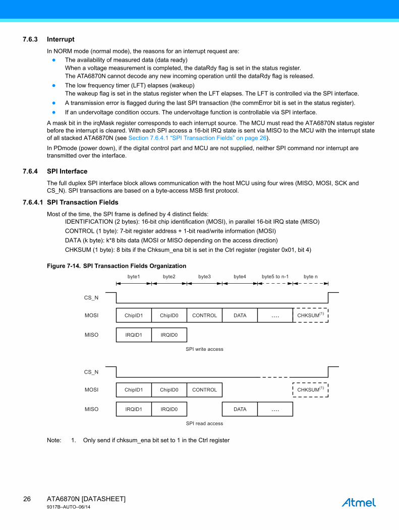
7.6.3 Interrupt
In NORM mode (normal mode), the reasons for an interrupt request are:
● The availability of measured data (data ready)When a voltage measurement is completed, the dataRdy flag is set in the status register.The ATA6870N cannot decode any new incoming operation until the dataRdy flag is released.
● The low frequency timer (LFT) elapses (wakeup)The wakeup flag is set in the status register when the LFT elapses. The LFT is controlled via the SPI interface.
● A transmission error is flagged during the last SPI transaction (the commError bit is set in the status register).
● If an undervoltage condition occurs. The undervoltage function is controllable via SPI interface.
A mask bit in the irqMask register corresponds to each interrupt source. The MCU must read the ATA6870N status register before the interrupt is cleared. With each SPI access a 16-bit IRQ state is sent via MISO to the MCU with the interrupt state of all stacked ATA6870N (see Section 7.6.4.1 “SPI Transaction Fields” on page 26).
In PDmode (power down), if the digital control part and MCU are not supplied, neither SPI command nor interrupt are transmitted over the interface.
7.6.4 SPI Interface
The full duplex SPI interface block allows communication with the host MCU using four wires (MISO, MOSI, SCK and CS_N). SPI transactions are based on a byte-access MSB first protocol.
7.6.4.1 SPI Transaction Fields
Most of the time, the SPI frame is defined by 4 distinct fields:IDENTIFICATION (2 bytes): 16-bit chip identification (MOSI), in parallel 16-bit IRQ state (MISO)
CONTROL (1 byte): 7-bit register address + 1-bit read/write information (MOSI)
DATA (k byte): k*8 bits data (MOSI or MISO depending on the access direction)
CHKSUM (1 byte): 8 bits if the Chksum_ena bit is set in the Ctrl register (register 0x01, bit 4)
Figure 7-14. SPI Transaction Fields Organization
Note: 1. Only send if chksum_ena bit set to 1 in the Ctrl register
byte5 to n-1 byte nbyte4byte3byte2
ChipID0 CONTROL
IRQID0
ChipID1
IRQID1
ChipID0
....
CHKSUM(1)
DATA
.... CHKSUM(1)DATA
SPI write access
SPI read access
CONTROL
IRQID0
ChipID1
IRQID1
MISO
MOSI
CS_N
MISO
MOSI
CS_N
byte1
ATA6870N [DATASHEET]9317B–AUTO–06/14
26

7.6.4.2 Identification Field
Atmel ATA6870N Chip Identification
The two chip identification bytes are sent over MOSI to the Atmel® ATA6870N(n) in the chain. The ATA6870N(n) checks the LSB. When LSB=1, the information is for this device. The SPI address will be decoded and the information processed. Independent from this the identification bytes are shifted by one bit to the right and transferred to the next ATA6870N(n) in the chain. The 2 identification bytes allows the identification of up to 16 ATA6870Ns.
Figure 7-15. Identification Field: Chip-ID Reception
IDENTIFICATION FIELD
0x00 DATACONTROL0x04
0x00
CS_N
ATA6870N (2)MOSI_IN
ATA6870N (3)MOSI_IN
ATA6870N (n>4)MOSI_IN
ATA6870N (4)MOSI_IN
ATA6870N (1)MOSI_IN
ATA6870N (4) identificationfield has lsb = 1 => decodeSPI access.Shift it ”on the fly” onceto the right
ATA6870N (>4) identificationfield has lsb = 0 => device is notaffected.Shift it ”on the fly” onceto the right
ATA6870N (1->3) identificationfield has lsb = 0 => device is notaffected.Shift it ”on the fly” onceto the right
DATACONTROL0x08
0x00 DATACONTROL0x00
0x00 DATACONTROL0x01
0x00 DATACONTROL0x02
27ATA6870N [DATASHEET]9317B–AUTO–06/14

7.6.4.3 ATA6870N IRQ Identification
Figure 7-16. IRQ Propagation Scheme
ATA6870N(n) IRQ output is connected to ATA6870N(n-1) IRQ_IN input.
ATA6870N(n-1) IRQ output is a logic OR between IRQ_IN and its internal irq_int signal.
ATA6870N(1) IRQ output is connected to MCU.
Figure 7-17. Identification Field: Interrupt State Emission
ATA6870N (n)
irq_intIRQ
IRQ_IN
ATA6870N (n-1)
irq_intIRQ
IRQ_IN
MCU
ATA6870N (1)
irq_intIRQ
IRQ_IN
≥1
≥1
≥1
Master SPI receivesidentification word = 0x2000 = 213 = 2m.This means ATA6870N number(16-m = 16-13) = 3 has IRQ pending.
ATA6870N (3) IRQ is set. =>ATA6870N (3) sets the MSB of thefirst byte to be shifted out. Othersbits are those coming from upperATA6870, shifted once to the right.
Others ATA6870Ns assert the MSBof the first byte to 0. Others bits arethose coming from upper ATA6870N,shifted once to the right.
0x20 0x00
CS_N
ATA6870N (1)MISO
ATA6870N (2)MISO
ATA6870N (16)MISO
ATA6870N (3)MISO
0x00 0x00
0x80 0x00
0x40 0x00
Note:n = IC number 1 < = n < = 16m = bit number 0 < = m < = 15m = n -1
ATA6870N [DATASHEET]9317B–AUTO–06/14
28

With each SPI access, a 16- bit IRQ state is send via MISO synchronous to the identification field to the MCU with the interrupt state of all stacked Atmel ATA6870N. The MCU, interrupted by an ATA6870N, has to send the identification field to check the IRQ levels (in that case the checksum is not considered). It is also possible to continue the transaction with CONTROL and DATA field. The MCU decodes the identification field shifted in MISO input. When bit m is set, ATA6870N(16-m) is requesting interrupt.
Figure 7-18. Identification Field
7.6.4.4 CONTROL Field
The CONTROL field defines the register to access and the direction (read/write). The size of the data (8, 16, or 112 bits) is defined by the address value in the CONTROL field.
7.6.4.5 DATA Field
The DATA field can be composed of 1, 2, or 14 bytes depending on the accessed register. Irrespective of the data direction, a byte is always transmitted with MSB first; a multi-byte word is transmitted with MSByte first.
Figure 7-19. CONTROL and DATA Fields - 8-bits Register Write
Figure 7-20. CONTROL and DATA Fields - 8-bits Register Read
M(12)M(13) M(10) M(9) M(3) M(1)M(2)M(6) M(4)M(5)M(7)M(8)M(11)M(16) M(14)M(15)
SCK
MISO
MOSI
CS_N
I(13)I(12) I(15) I(16)I(14)I(9) I(11)I(10)I(5)I(4) I(7) I(8)I(6)I(1) I(3)I(2)
Table 7-15. Control Field
CONTROL Field Bit7 Bit6 Bit5 Bit4 Bit3 Bit2 Bit1 Bit0
A6 A5 A4 A3 A2 A1 A0 W/Rd
A(6) A(5)
Data not relevantData not relevant
A(0) D(5) D(4) D(3) D(2) D(1) D(0)D(7) D(6)1A(2) A(1)A(4) A(3)
SCK
MISO
MOSI
CS_N
A(6) A(5)
Data not relevant
Data not relevantA(0)
D(5) D(4) D(3) D(2) D(1) D(0)D(7) D(6)
0A(2) A(1)A(4) A(3)
SCK
MISO
MOSI
CS_N
29ATA6870N [DATASHEET]9317B–AUTO–06/14

Figure 7-21. CONTROL and DATA Fields - 16-bits Register Write
Figure 7-22. CONTROL and DATA Fields - 16-bits Register Read
In order to retrieve results from all channels in one Atmel® ATA6870N without having to request for each channel, an SPI 112-bit read-only "burst access" (dataRd16Burst register; address = 0x7F) is implemented. When requested, the ATA6870N outputs its 6 voltage channels V6 to V1 and one of the two temperature channels T2 and T1 in sequence on the SPI bus. The diagrams below show the CONTROL and DATA fields of such an access.
Data not relevantData not relevantData not relevant
A(6) A(5) A(0) D(9) D(8) D(7) D(6) D(5) D(2) D(1) D(0)D(3)D(4)D(11) D(10)D(13) D(12)D(15) D(14)1A(2) A(1)A(4) A(3)
SCK
MISO
MOSI
CS_N
Data not relevant
A(6) A(5) A(0)
D(9) D(8) D(7) D(6) D(5) D(2) D(1) D(0)D(3)D(4)D(11) D(10)D(13) D(12)D(15) D(14)
0A(2) A(1)A(4) A(3)
SCK
MISO
MOSI
CS_N
ATA6870N [DATASHEET]9317B–AUTO–06/14
30

Figure 7-23. CONTROL and DATA Fields - 112-bits Register Read
One Atmel® ATA6870N frame corresponds to the set of results obtained in one Atmel ATA6870N. An Atmel ATA6870N frame is formatted as follows:
Figure 7-24. SPI Access to dataRd16burst Register 0x7F
When reading data of chained ATA6870N, data is transferred as follow:
Data not relevant
1 1 1
D(9) D(8)
Channel V6
D(7) D(6) D(5) D(2) D(1) D(0)D(3)D(4)D(11) D(10)0 00 0
01 11 1
SCK
MISO
MOSI
CS_N
D(9) D(8) D(7) D(6) D(5) D(2) D(1) D(0)D(3)D(4)D(11) D(10)0 00 0
SCK
MISO
MOSI
CS_N
D(9) D(8) D(7) D(6) D(5) D(2) D(1) D(0)D(3)D(4)D(11) D(10)0 00 0
SCK
MISO
MOSI
CS_N
Channel V1
Channel temperature T1 or T2
ADC3 ADC2 ADCTADC1
Padding: 0x00 12-bit ADC data lsbmsb
ADC6 ADC5 ADC4
Voltage channels Temp channel
16 bit 16 bit 16 bit16 bit16 bit 16 bit 16 bit
31ATA6870N [DATASHEET]9317B–AUTO–06/14

Figure 7-25. Example with two Atmel ATA6870N in a Chain
7.6.4.6 Communication Error
Correct communication can be verified using various functions of the Atmel ATA6870N.
For internal synchronization, it is mandatory to keep CLK running during any SPI access; CLK must be set on 4 clock cycles (at least) before SPI access starts, and must be kept on 4 clock cycles (at least) after SPI access ends up. Keeping at least 4 CLK clock cycles between two consecutive SPI accesses is mandatory. If this is not the case, the Atmel ATA6870Ns will detect an error in communication. The CommError bit will be set in the status register 0x06).
Figure 7-26. SPI Access and CLK Activity
The Atmel ATA6870N verifies that complete bytes (8bits long) are always transmitted. A transition starts when CS_N goes to low and it ends when CS_N goes to high. The number of clock cycles (signal SCK) is monitored during the transition. This number of clock cycles has to be modulo 8. If the CS_N length is not modulo 8 clock cycles, the bit CommError is set in the status register. This will cause an interrupt to the MCU if the CommError is not masked by the commErrorMsk bit in the IrqMask register.
7.6.4.7 CHKSUM Field
The Atmel® ATA6870N provides the possibility of verifying the transmitted data using a checksum. Setting chksum_ena bit to 1 in the Ctrl register (default = 0) activates the checksum feature.
The chksum field is an 8-bit checksum computed from the proceeding data (control and data fields, byte 3 to byte n-1). It is based on the polynomial x8+x2+x1+1. The way it is computed is depicted below:
Figure 7-27. LFSR-based Checksum Computation
The checksum is calculated from the CONTROL field and DATA field by a polynomial division. The DATA field can consist of 1 byte up to 14 bytes (112-bit read-only “burst access”). The IDENTIFICATION field (2 bytes) is not used to generate the checksum. The checksum is always sent by the microcontroller, independent of read write mode.
The checksum is in the LFSR (linear feedback shift register) when the complete bitstream (the whole fields of the transaction) followed by 0x00 have been shifted in the LFSR.
The checksum verification on the complete data transmission was OK when the complete bitstream followed by the checksum have been shifted in the LFSR, and the content of the LFSR is 0x00. If this is not the case, the receiving ATA6870N will set the chkError bit in the status register. This will cause an interrupt to the MCU if the chkError is not masked by the chkErrorMsk bit in the IrqMask register. See the example below. The checksum is serially computed from the 8-bit value 0x57. So the bitstream 0x5700 is shifted in the LFSR. The resulting checksum is [f6o, f6i, f5i … f0i] at the last shift in cycle:
SPI Clock
Rd Reg command chip1
ATA6870 #1 Frame ATA6870 #2 Frame
Rd Reg command chip2
SPI ClockSCK
MISO
MOSI
CS_N
CLK OFF
SPI ACCESS SPI ACCESS
4 clk_ticks 4 clk_ticks 4 clk ticks
CLK_OFFCLK ON
F4i F5i F6oF6iF3iF2iF1iserial bitstream
MSB first
F0i
z-1 z-1 z-1z-1 z-1z-1z-1
ATA6870N [DATASHEET]9317B–AUTO–06/14
32

During an SPI write access, the checksum is computed by the MCU and sent MSB first in the CHKSUM field. For an SPI read access, the checksum is computed by the Atmel® ATA6870N and is checked by the MCU. During CHKSUM, MCU has to send 0x00 on MOSI, and must check that its own LFSR equals 0x00 at the end of CHKSUM field.
7.6.4.8 Device Position
For the Atmel ATA6870N (1), this is the device on the lowest level, the SPI has to work as a standard logic CMOS interface to the MCU. The SPI’s between stacked ATA6870N have to work as level-shifters based on current sources. These different physical interfaces can be selected by the Pin MFIRST.
Table 7-16. checksum = [f6o, f6i, ... f0i] = 0xA2
Input f01 f1i f2i f3i f4i f5i f6i f6o
X 0 0 0 0 0 0 0 0
5D
0 0 0 0 0 0 0 0 0
1 1 0 0 0 0 0 0 0
0 0 1 0 0 0 0 0 0
1 1 0 1 0 0 0 0 0
7D
0 0 1 0 1 0 0 0 0
1 1 0 1 0 1 0 0 0
1 1 1 0 1 0 1 0 0
1 1 1 1 0 1 0 1 0
0D
0 0 1 1 1 0 1 0 1
0 1 1 0 1 1 0 1 0
0 0 1 1 0 1 1 0 1
0 1 1 0 1 0 1 1 0
0 0 1 1 0 1 0 1 1
0 1 1 0 1 0 1 0 1
0 1 0 0 0 1 0 1 0
0 0 1 0 0 0 1 0 1
0x2 0xA
Table 7-17. Device Position
MFIRST Configuration
0 ATA6870N (2) to ATA6870N (n)
1 ATA6870N (1)
Table 7-18. Electrical Characteristics
No. Parameters Test Conditions Pin Symbol Min. Typ. Max. Unit Type*
12.1 High level input voltage MFIRST MFIRST0.7 ×
DVDDV A
12.2 Low level input voltage MFIRST MFIRST0.3 ×
DVDDV A
12.3 Hysteresis MFIRST MFIRST0.05 × DVDD
V C
12.4 Input current VMFIRST = 0V to VDVDD MFIRST MFIRST –1 +1 µA A
*) Type means: A = 100% tested, B = 100% correlation tested, C = Characterized on samples, D = Design parameter
33ATA6870N [DATASHEET]9317B–AUTO–06/14

7.6.5 Digital Inputs and Outputs
7.6.5.1 Digital Output Characteristics
Digital Output Characteristics (MISO, IRQ)
If the Atmel® ATA6870N is configured as first IC (master) in a string (MFIRST = 1), these pins are configured as an open drain output. If the ATA6870N is configured to be a stacked IC (MFIRST = 0), the output signals MISO and IRQ coming from the upper IC need to be transferred to the MISO and IRQ outputs of the master in the string via the MISO_IN and IRQ_IN inputs. In this case the MISO and IRQ outputs act as level shifters based on current sources.
Digital Output Characteristics (MOSI_OUT, SCK_OUT, CS_N_OUT, CLK_OUT)
These outputs act as level shifters based on current sources. They transfer the input signals MOSI_OUT, SCK_OUT, CS_N_OUT, CLK_OUT to the next IC above. If the ATA6870N is the IC on the top level of a string, these outputs must be connected to VDDHV.
7.6.5.2 Digital Input Characteristics
Digital Input Characteristics (MISO_IN, IRQ_IN)
Table 7-19. Electrical Characteristics
No. Parameters Test Conditions Pin Symbol Min. Typ. Max. Unit Type*
13.1 Low level output voltageIOUT = +5mAMFIRST = 1
MISO, IRQ VMISO, VIRQ0.2 × VDD
V A
13.2 Low level output current ±0.3V, MFIRST = 0 MISO, IRQ IMISO, IIRQ –13 –8 µA A
13.3 High level output current ±0.3V, MFIRST = 0 MISO, IRQ IMISO, IIRQ –65 –40 µA A
*) Type means: A = 100% tested, B = 100% correlation tested, C = Characterized on samples, D = Design parameter
Table 7-20. Electrical Characteristics
No. Parameters Test Conditions Pin Symbol Min. Typ. Max. Unit Type*
14.1 Low level output currentVDDHV + 1V to VDDHV + 2V
(1) V(1) 25 55 µA A
14.2 High level output currentVDDHV + 1V to VDDHV + 2V
(1) V(1) –1 +1 µA A
*) Type means: A = 100% tested, B = 100% correlation tested, C = Characterized on samples, D = Design parameter
Note: 1. MOSI_OUT, SCK_OUT, CS_N_OUT, CLK_OUT
Table 7-21. Electrical Characteristics
No. Parameters Test Conditions Pin Symbol Min. Typ. Max. Unit Type*
15.1 Low level input current(VDDHV + 1.4V) ±0.3V
MISO_IN, IRQ_IN
IMISO_IN IIRQ_IN
13 µA A
15.2 High level input current(VDDHV + 1.4V) ±0.3V
MISO_IN, IRQ_IN
IMISO_IN IIRQ_IN
40 µA A
*) Type means: A = 100% tested, B = 100% correlation tested, C = Characterized on samples, D = Design parameter
ATA6870N [DATASHEET]9317B–AUTO–06/14
34

Digital Input Characteristics (CS_N, SCK, MOSI, CLK)
7.6.5.3 Test-mode Pins
The test-mode pins DTST, ATST, PWTST (outputs) have to be kept open in the application. The test-mode pins SCANMODE and CS_FUSE (inputs) have to be connected to VSSA. These inputs have an internal pull-down resistor. The test-mode pin VDDFUSE is a supply pin. It must also be connected to VSSA.
Table 7-22. Electrical Characteristics
No. Parameters Test Conditions Pin Symbol Min. Typ. Max. Unit Type*
16.1 High level input voltage MFIRST = 1 (1) V(1) 0.7 × DVDD
DVDD V A
16.2 Low level input voltage MFIRST = 1 (1) V(1) 0.3 × DVDD
V A
16.3 High level input current MFIRST = 1 I(1) 50 100 µA A
16.4 Low level input current MFIRST = 1 I(1) –130 –70 µA A
16.5 Low level input currentMFIRST = 0, V(1) = 1V to 2V
(1) I(1) –55 –35 µA A
16.6 High level input currentMFIRST = 0V(1) = 1V to 2V
(1) I(1) –1 +1 µA A
*) Type means: A = 100% tested, B = 100% correlation tested, C = Characterized on samples, D = Design parameter
Note: 1. CS_N, SCK, MOSI, CLK
Table 7-23. Input Characteristics Pins SCANMODE, CS_FUSE, VDDFUSE
No. Parameters Test Conditions Pin Symbol Min. Typ. Max. Unit Type*
18.1 Pull-down resistorSCANMODE,
CS_FUSERSCANMODE, RCS_FUSE
50 200 kΩ A
*) Type means: A = 100% tested, B = 100% correlation tested, C = Characterized on samples, D = Design parameter
35ATA6870N [DATASHEET]9317B–AUTO–06/14
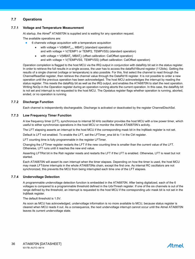
7.7 Operations
7.7.1 Voltage and Temperature Measurement
At startup, the Atmel® ATA6870N is supplied and is waiting for any operation request.
The available operations are:
● 6 channels voltage acquisition with a temperature acquisition
● with voltage = V(MBATi+1, MBATi) (standard operation)and with voltage = V(TEMP1 or TEMP2, TEMPVSS) (standard operation)
● with voltage = V(MBATi, MBATi) (offset calibration: CalOffset operation)and with voltage = V(TEMPVSS, TEMPVSS) (offset calibration: CalOffset operation)
Operation completion is flagged to the host MCU via the IRQ output in conjunction with dataRdy bit set in the status register. In order to retrieve the full results in a single access, the user has to access the dataRd16burst register (112bits). Getting the results of a single channel (voltage or temperature) is also possible. For this, first select the channel to read through the ChannelReadSel register, then retrieve the channel value through the DataRd16 register. It is not possible to order a new operation until the previous operation has been acknowledged. The host MCU acknowledges the interrupt by reading the status register. This resets the dataRdy bit as well as the IRQ output, and enables the ATA6870N to start the next operation. Writing NoOp in the Operation register during an operation running aborts the current operation. In this case, the dataRdy bit is not set and interrupt is not requested to the host MCU. The Opstatus register flags whether operation is running, aborted, ended, or no operation is running.
7.7.2 Discharge Function
Each channel is independently dischargeable. Discharge is activated or deactivated by the register ChannelDischSel.
7.7.3 Low Frequency Timer Function
A low frequency timer (LFT), synchronous to internal 50 kHz oscillator provides the host MCU with a low power timer, which useful to either synchronize operations in the host MCU or monitor the Atmel ATA6870N’s activity.
The LFT elapsing asserts an interrupt to the host MCU if the corresponding mask bit in the IrqMask register is not set.
Default is LFT not enabled. To enable the LFT, set the LFTimer_ena bit to 1 in the Ctrl register.
LFT counting time is fully programmable in the register LFTimer.
Changing the LFTimer register restarts the LFT if the new counting time is smaller than the current value of the LFT. Otherwise, LFT runs until it reaches the new end value.
Asserting LFTRst bit in the Rstr register resets and restarts the LFT if the LFT is enabled. Otherwise, LFT is reset but not started.
Each ATA6870N will assert its own interrupt when the timer elapses. Depending on how the timer is used, the host MCU may mask LFTdone interrupts in the whole ATA6870Ns chain, except the first one. As internal RC oscillators are not synchronized, this prevents the MCU from being interrupted each time one of the LFT elapses.
7.7.4 Undervoltage Detection
A programmable undervoltage detection function is embedded in the ATA6870N. After being digitalized, each of the 6 voltages is compared to a programmable threshold defined in the UdvThresh register. If one of the six channels is out of the range defined by the threshold, an interrupt is requested to the host MCU if the corresponding udv mask bit is not set in the IrqMask register.
The default threshold is 1.5V.
As soon as MCU has acknowledged, undervoltage information is no more available to MCU, because status register is cleared when MCU reads it out. As a consequence, the next undervoltage interrupt cannot occur until the Atmel ATA6870N leaves its current undervoltage state.
ATA6870N [DATASHEET]9317B–AUTO–06/14
36

7.8 Registers
Registers are read and written through the SPI interface.
7.8.1 Registers Content
7.8.1.1 RevID Register
Table 7-24. Register Mapping
Register Address
Control Field Read Mode
Control Field Write Mode Register Name Access Type Function
0x00 0x00 - RevID R 8 bits Revision ID/value Mfirst, pow_on
0x01 0x02 0x03 Ctrl RW 8 bits Control register
0x02 0x04 0x05 Operation RW 8 bits Operation request
0x03 0x06 - OpStatus R 8 bits Operation status
0x04 - 0x09 Rstr W 8 bits Software reset
0x05 0x0A 0x0B IrqMask RW 8 bits Mask interrupt sources
0x06 0x0C - Status R 8 bits Status interrupt sources
0x08 0x10 - ChannelUdvStatus R 8 bits Channels undervoltage status
0x09 0x12 0x13 ChannelDischSel RW 8 bits Select channel to discharge
0x0A 0x14 0x15 ChannelReadSel RW 8 bits Select channel to read
0x0B 0x16 0x17 LFTimer RW 8 bits Low frequency timer control
0x0C 0x18 - CalibStatus R 8 bits Reserved
0x0D 0x1A 0x1B FuseCtrl RW 8 bits Reserved
0x10 0x20 0x21 UdvThresh RW 16 bits Undervoltage detection threshold
0x11 0x22 - DataRd16 R 16 bitsSingle access to selected channel value
0x12 0x24 0x25 ATA6870NTest RW 16 bits Reserved
0x7F 0xFE - DataRd16Burst R 112 bitsBurst Access to the whole channels (6 voltage and 1 temperature)
Table 7-25. RevId Register Overview
Register RevID
Address 0x00 Reset Value 0x02
7 (msb) 6 5 4 3 2 1 0 (lsb)
x x x pow_en Mfirst RevID
Table 7-26. RevId Register Content
Bit Field Description
RevID ATA6870N revision number, revision B: 0x02
Mfirst Status input pin MFIRST
pow_en Status input pin POW_EN
37ATA6870N [DATASHEET]9317B–AUTO–06/14
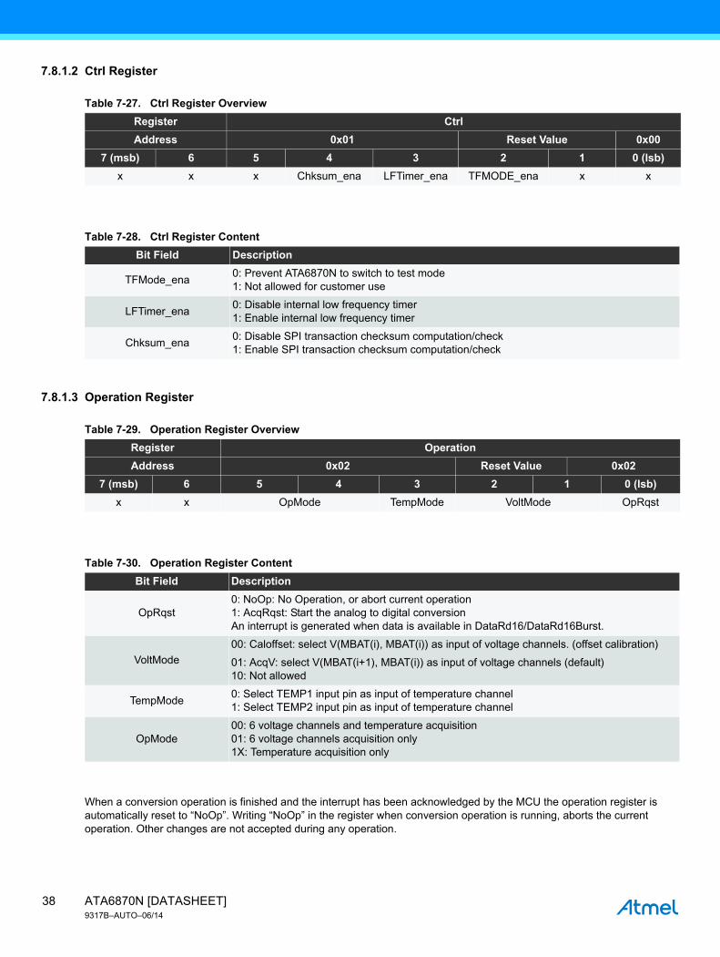
7.8.1.2 Ctrl Register
7.8.1.3 Operation Register
When a conversion operation is finished and the interrupt has been acknowledged by the MCU the operation register is automatically reset to “NoOp”. Writing “NoOp” in the register when conversion operation is running, aborts the current operation. Other changes are not accepted during any operation.
Table 7-27. Ctrl Register Overview
Register Ctrl
Address 0x01 Reset Value 0x00
7 (msb) 6 5 4 3 2 1 0 (lsb)
x x x Chksum_ena LFTimer_ena TFMODE_ena x x
Table 7-28. Ctrl Register Content
Bit Field Description
TFMode_ena0: Prevent ATA6870N to switch to test mode1: Not allowed for customer use
LFTimer_ena0: Disable internal low frequency timer1: Enable internal low frequency timer
Chksum_ena0: Disable SPI transaction checksum computation/check1: Enable SPI transaction checksum computation/check
Table 7-29. Operation Register Overview
Register Operation
Address 0x02 Reset Value 0x02
7 (msb) 6 5 4 3 2 1 0 (lsb)
x x OpMode TempMode VoltMode OpRqst
Table 7-30. Operation Register Content
Bit Field Description
OpRqst0: NoOp: No Operation, or abort current operation1: AcqRqst: Start the analog to digital conversionAn interrupt is generated when data is available in DataRd16/DataRd16Burst.
VoltMode
00: Caloffset: select V(MBAT(i), MBAT(i)) as input of voltage channels. (offset calibration)
01: AcqV: select V(MBAT(i+1), MBAT(i)) as input of voltage channels (default)10: Not allowed
TempMode0: Select TEMP1 input pin as input of temperature channel1: Select TEMP2 input pin as input of temperature channel
OpMode00: 6 voltage channels and temperature acquisition01: 6 voltage channels acquisition only1X: Temperature acquisition only
ATA6870N [DATASHEET]9317B–AUTO–06/14
38

Figure 7-28. Typical Data Acquisition Flow
7.8.1.4 OpStatus Register
Conversion FinishedOpstatus = Result Available
Status = Data ReadyIRQ DATA RDY
ASIC3Read/Check Opstatus
Read/Check Status
ASIC2Read/Check Opstatus
Read/Check Status
ASIC1Read/Check Opstatus
Read/Check Status
ASIC1 (MFIRST = 1) MCU
Set Operation = ACQ*/CAL*
...
...
ASIC3 Burst Read DataASIC2 Burst Read DataASIC1 Burst Read Data
Background Tasks/Idle
Runs ConversionOpstatus = Running
Init StateOpstatus = NoOP
Status Cleared
Opstatus = NoOPIRQ Acknowledged
Status Cleared
Conversion FinishedOpstatus = Result Available
Status = Data ReadyIRQ DATA RDY
ASIC2 (MFIRST = 0)
Runs ConversionOpstatus = Running
Opstatus = NoOPStatus Cleared
Opstatus = NoOPStatus Cleared
Init StateOpstatus = NoOP
Status Cleared
Conversion FinishedOpstatus = Result Available
Status = Data ReadyIRQ DATA RDY
ASIC3 (MFIRST = 0)
Runs ConversionOpstatus = Running
Init StateOpstatus = NoOP
Status Cleared
Table 7-31. OpStatus Register Overview
Register OpStatus
Address 0x03 Reset Value 0x00
7 (msb) 6 5 4 3 2 1 0 (lsb)
x x x x x x OpStatus
Table 7-32. OpStatus Register Content
Bit Field Description
OpStatus
00: No Operation01: Operation is ongoing10: Operation is finished, result is available11: Operation is cancelled, result is not available
39ATA6870N [DATASHEET]9317B–AUTO–06/14

Figure 7-29. Operation Status Register Management
The OPStatus register is reset when read after a completed or aborted operation. Reading the register before starting an operation is not mandatory. Reading data conversion results or reading the OpStatus register during an operation does not affect the OpStatus register.
7.8.1.5 Rstr Register
LFTRst resets and restarts the low frequency timer if not disabled (LFTimer_ena = 0).
7.8.1.6 IrqMask Register
Operation Finished,Result Available
Operation Aborted,Result not Available
Operation Running
End of conversionUsers programs NoOp
Status reg has been read and:User programs conversion operation or
reads operation status register
User programs conversion operation orreads operation status register
Users programs conversions operation
User reads Operation Status Register,Reset
NO OP
Table 7-33. Rstr Register Overview
Register Rstr
Address 0x04 Reset Value 0x00
7 (msb) 6 5 4 3 2 1 0 (lsb)
x x x x x x LFTRst 0
Table 7-34. Rstr Register Content
Bit Field Description
LFTRst0: No reset1: Low Frequency Timer software reset
Table 7-35. IrqMask Register Overview
Register IrqMask
Address 0x05 Reset Value 0x00
7 (msb) 6 5 4 3 2 1 0 (lsb)
x x x chkErrorMask udvmask commErrorMask LFTdoneMask dataDryMask
ATA6870N [DATASHEET]9317B–AUTO–06/14
40

7.8.1.7 Status Register
Any bit among {dataRdy, LFTdone, commError, udv, chkError} set in the status register requests an interrupt to the external MCU if the corresponding mask bit in the IrqMask register is 0. Reading the status register acknowledges the interrupt and resets its content. Por and TFMdeOn cause no interrupt.
7.8.1.8 ChannelUdvStatus Register
Table 7-36. IrqMask Register Content
Bit Field Description
dataRdyMask Mask data ready interrupt when set to 1
WakeupMask Mask LFTdone interrupt when set to 1
commErrorMask Mask commError interrupt when set to 1
udvMask Mask undervoltage detection interrupt when set to 1
chkErrorMask Mask checksum error interrupt when set to 1
Table 7-37. Status Register Overview
Register Status
Address 0x06 Reset Value 0x20
7 (msb) 6 5 4 3 2 1 0 (lsb)
x TFMdeOn por chkError udv commError LFTdone dataRdy
Table 7-38. Status Register Content
Bit Field Description
dataRdy Conversion finished
LFTdone Low frequency timer elapsed
commError Bad SPI command detected (wrong length)
udv Undervoltage detected
chkError Error on checksum check
Por Power on reset detected
TFMdeOn Test mode on
Table 7-39. ChannelUdvStatus Register Overview
Register ChannelUdvStatus
Address 0x08 Reset Value 0x00
7 (msb) 6 5 4 3 2 1 0 (lsb)
x x chUdv6_stat chUdv5_stat chUdv4_stat chUdv3_stat chUdv2_stat chUdv1_stat
41ATA6870N [DATASHEET]9317B–AUTO–06/14
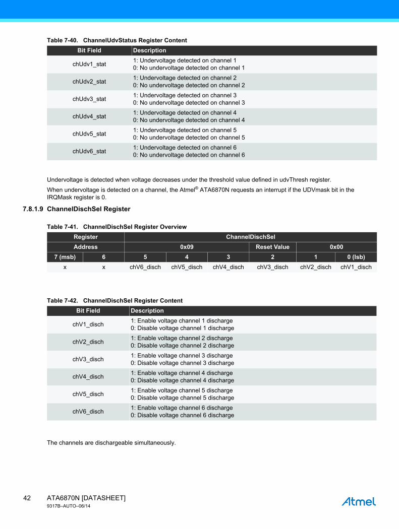
Undervoltage is detected when voltage decreases under the threshold value defined in udvThresh register.
When undervoltage is detected on a channel, the Atmel® ATA6870N requests an interrupt if the UDVmask bit in the IRQMask register is 0.
7.8.1.9 ChannelDischSel Register
The channels are dischargeable simultaneously.
Table 7-40. ChannelUdvStatus Register Content
Bit Field Description
chUdv1_stat1: Undervoltage detected on channel 10: No undervoltage detected on channel 1
chUdv2_stat1: Undervoltage detected on channel 20: No undervoltage detected on channel 2
chUdv3_stat1: Undervoltage detected on channel 30: No undervoltage detected on channel 3
chUdv4_stat1: Undervoltage detected on channel 40: No undervoltage detected on channel 4
chUdv5_stat1: Undervoltage detected on channel 50: No undervoltage detected on channel 5
chUdv6_stat1: Undervoltage detected on channel 60: No undervoltage detected on channel 6
Table 7-41. ChannelDischSel Register Overview
Register ChannelDischSel
Address 0x09 Reset Value 0x00
7 (msb) 6 5 4 3 2 1 0 (lsb)
x x chV6_disch chV5_disch chV4_disch chV3_disch chV2_disch chV1_disch
Table 7-42. ChannelDischSel Register Content
Bit Field Description
chV1_disch1: Enable voltage channel 1 discharge0: Disable voltage channel 1 discharge
chV2_disch1: Enable voltage channel 2 discharge0: Disable voltage channel 2 discharge
chV3_disch1: Enable voltage channel 3 discharge0: Disable voltage channel 3 discharge
chV4_disch1: Enable voltage channel 4 discharge0: Disable voltage channel 4 discharge
chV5_disch1: Enable voltage channel 5 discharge0: Disable voltage channel 5 discharge
chV6_disch1: Enable voltage channel 6 discharge0: Disable voltage channel 6 discharge
ATA6870N [DATASHEET]9317B–AUTO–06/14
42

7.8.1.10 ChannelReadSel Register
This register can be used to quickly read a single channel without using a full burst access. The value of the selected channel will be available in the DataRd16 register. The value will always be updated by writing a channel address to the ChannelReadSel register. Data in this register is not valid during ongoing data conversion.
7.8.1.11 LFTimer Register
The default timer value is 59.965s (0xF9) for fOSC = 50kHz.
Table 7-43. ChannelReadSel Register Overview
Register ChannelReadSel
Address 0x0A Reset Value 0x00
7 (msb) 6 5 4 3 2 1 0 (lsb)
ChannelReadSel
Table 7-44. ChannelReadSel Register Content
Bit Field Description
ChannelReadSel
111: Value of the LFT is returned in DataRd16 register110: Temperature channel available in DataRd16 register101: Voltage channel6, value available in DataRd16 register100: Voltage channel5, value available in DataRd16 register011: Voltage channel4, value available in DataRd16 register010: Voltage channel3, value available in DataRd16 register001: Voltage channel2, value available in DataRd16 register000: Voltage channel1, value available in DataRd16 register
Table 7-45. LFTimer Register Overview
Register LFTimer
Address 0x0B Reset Value 0xF9
7 (msb) 6 5 4 3 2 1 0 (lsb)
LFTPrescaler LFTDelay
Table 7-46. LFTimer Register Content
Bit Field Description
LFTDelay Contains the present low frequency timer delay value
LFTPrescaler0: PrescalerValue = 11: PrescalerValue = 6
43ATA6870N [DATASHEET]9317B–AUTO–06/14

Figure 7-30. Block Diagram LFTimer
Formula for Delay Time calculation:
The LFT can be programmed to the following values (fOSC = 50kHz):
LFTprescaler = 0: 0.082s <= duration <= 10.486s, Increment = 82msLFTprescaler = 1: 492 ms <= duration <= 62.915s, Increment = 492ms
When LFT elapsed, an interrupt is requested unless LFTdoneMask bit is set in the IRQMask register.
For details on the tolerances for the oscillator, see Section 7.5.6 “RC Oscillator” on page 24.
Keeping at list 100 µs between two successive LFTimer register write accesses prevents internal metastability issues, which might result in bad LFTdelay decoding.
7.8.1.12 Test-Mode Register
Test-mode registers 1, 2, and 3 are reserved for the factory calibration process. They are not allowed for customer use.
7-bitcounter
Delay Time elapsedComp
LFTprescaler LFTdelay
/6
/409650kHz
clear
Delay Time1
TOSC[Hz]------------------------ 4096 6
LFTprescalerD( ) LFTdelayD 1+( )×××=
Table 7-47. Test-Mode Register 1 Overview
Register TESTmode1
Address 0x0C Reset Value 0x03
7 (msb) 6 5 4 3 2 1 0 (lsb)
0 0 0 0 0 0 1 1
Table 7-48. Test-Mode Register 2 Overview
Register TESTmode2
Address 0x0D Reset Value 0x07
7 (msb) 6 5 4 3 2 1 0 (lsb)
0 0 0 0 0 1 1 1
Table 7-49. Test-Mode Register 3 Overview
Register UdvThresh
Address 0x12 Reset value 0x0E00
15 14 13 12 11 10 9 8 7 6 5 4 3 2 1 0
0 0 0 0 0 1 1 1 1 0 0 0 0 0 0 0
ATA6870N [DATASHEET]9317B–AUTO–06/14
44

7.8.1.13 UdvThresh Register
Default value is 1.5V (0x0570, 1392D)
1.5V = VREF × (1392 – 410) / (1502 – 410)
See also Section 7.5.1.2 “12 Bits Incremental ADC” on page 18.
7.8.1.14 DataRd16 Register
Table 7-50. UdvThresh Register Overview
Register UdvThresh
Address 0x10 Reset value 0x0570
15 14 13 12 11 10 9 8 7 6 5 4 3 2 1 0
x x x x udvThresh
Table 7-51. UdvThresh Register Content
Bit Field Format Description
udvThresh 12 bits Threshold for undervoltage detection
Table 7-52. DataRd16 Register Overview
Register DataRd16
Address 0x11 Reset value 0x0000
15 14 13 12 11 10 9 8 7 6 5 4 3 2 1 0
x x x x DataRd16
Table 7-53. DataRd16 Register Content
Bit Field Format Description
DataRd16 12 bitsReturn selected channel value (see Section 7.8.1.10 “ChannelReadSel Register” on page 43)
45ATA6870N [DATASHEET]9317B–AUTO–06/14

7.8.1.15 DataRd16burst Register
Table 7-54. DataRd16burst Register Overview
Register DataRd16Burst
Address 0x7F Reset value 0x0000
111 110 109 108 107 106 105 104 103 102 101 100 99 98 97 96
X X X x Channel6 data
95 94 93 92 91 90 89 88 87 86 85 84 83 82 81 80
x x x x Channel5 data
79 78 77 76 75 74 73 72 71 70 69 68 67 66 65 64
x x x x Channel4 data
63 62 61 60 59 58 57 56 55 54 53 52 51 50 49 48
x x x x Channel3 data
47 46 45 44 43 42 41 40 39 38 37 36 35 34 33 32
x x x x Channel2 data
31 30 29 28 27 26 25 24 23 22 21 20 19 18 17 16
x x x x Channel1 data
15 14 13 12 11 10 9 8 7 6 5 4 3 2 1 0
x x x x Temperature data
Table 7-55. DataRd16burst Register Content
Bit Field Format Description
DataRd16burst 112bitsReturns the values of all channels from one ATA6870N, including temperature measurement
ATA6870N [DATASHEET]9317B–AUTO–06/14
46

Figure 7-31. Application
Figure 7-31 shows an application with 2 stacked Atmel® ATA6870Ns.
MBAT6
CS
_N
CLK
SC
K
MO
SI
MIS
O
MFI
RS
T
DTS
T
SC
AN
MO
DE
CS
_FU
SE
DV
SS
VD
DFU
SE
DV
DD
DIS
CH
6
1kΩ
1.5kΩ
1kΩ
1kΩ
1kΩ
1kΩ
1kΩ 121kΩ
1kΩ
10nF
33μF 220nF
100nF
100nF
100nF
100nF
100nF
100nF
+
10Ω
MBAT5DISCH5
100nF
100nF
100nF
100nF
100nF
100nF
33μF 220nF
+
MB
AT7
VD
DH
V
IRQ
_IN
CLK
_OU
T
CS
_N_O
UT
SC
K_O
UT
MO
SI_
OU
T
MIS
O_I
N
PD
_N
VD
DH
VP
MBAT3
MBAT4DISCH4
DISCH3
MBAT2NTCNTC
DISCH2
ATA6870N
ATA6870N
MBAT1
10Ω
IRQ
DISCH1
VDDHVM
POW_ENAPD_N_OUT
TEMP2
BIASRESATST
PWTST
TEMPVREF
TEMPVSSTEMP1
GND
AVDD
AVSS
MBAT6
CS
_N
CLK
SC
K
MO
SI
MIS
O
MFI
RS
T
DTS
T
SC
AN
MO
DE
CS
_FU
SE
DV
SS
VD
DFU
SE
DV
DD
DIS
CH
6
1kΩ
1kΩ
1kΩ
1kΩ
1kΩ
1kΩ 121kΩ
1kΩ
10nF
MBAT5DISCH5
MB
AT7
VD
DH
V
IRQ
_IN
CLK
_OU
T
CS
_N_O
UT
SC
K_O
UT
MO
SI_
OU
T
MIS
O_I
N
PD
_N
VD
DH
VP
MBAT3
MBAT4DISCH4
DISCH3
MBAT2NTCNTC
DISCH2
MBAT1
10Ω
IRQ
DISCH1
VDDHVM
POW_ENAPD_N_OUT
TEMP2
CSNSCKMOSIMISO OUT
IRQ
VDD
Micro-controller
GND
CLK
BIASRESATST
PWTST
TEMPVREF
TEMPVSSTEMP1
GND
AVDD
AVSS
10Ω
10μF 100nF
+
10μF 100nF
+
47ATA6870N [DATASHEET]9317B–AUTO–06/14

9. Package Information
8. Ordering InformationExtended Type Number Package MOQ
ATA6870N-PLPW QFN48, 7 × 7 1,000 pieces
ATA6870N-PLQW QFN48, 7 × 7 4,000 pieces
Package Drawing Contact:[email protected]
GPC DRAWING NO. REV. TITLE
6.543-5130.01-4 3
09/07/11
Package: VQFN_7x7_48LExposed pad 5.6x5.6
COMMON DIMENSIONS(Unit of Measure = mm)
MIN NOM NOTEMAXSymbol
Standard Singulation process
Dimensions in mm
specificationsaccording to DINtechnical drawings
0.02 0.050.0A1
7 7.16.9E
0.23 0.30.16b0.5 BSCe
0.4 0.50.3L5.6 5.755.45E2
5.6 5.755.45D27 7.16.9D
0.2 0.250.15A3
0.9 10.8A
Top View
D
481
12
PIN 1 ID
E
Side View A3
A
A1
b
L
A (10:1)
Bottom View
e
D2
48 37
13
1
12
2425
36
E2
A
ATA6870N [DATASHEET]9317B–AUTO–06/14
48

9.1 Markings
As a minimum, the devices will be marked with the following:
● Date code (year and week number)
● Atmel® part number (ATA6870N)
10. Revision History
Please note that the following page numbers referred to in this section refer to the specific revision mentioned, not to this document.
Revision No. History
9317B-AUTO-06/14 • Put datasheet in the latest template
49ATA6870N [DATASHEET]9317B–AUTO–06/14

XX X XX XAtmel Corporation 1600 Technology Drive, San Jose, CA 95110 USA T: (+1)(408) 441.0311 F: (+1)(408) 436.4200 | www.atmel.com
© 2014 Atmel Corporation. / Rev.: Rev.: 9317B–AUTO–06/14
Atmel®, Atmel logo and combinations thereof, Enabling Unlimited Possibilities®, and others are registered trademarks or trademarks of Atmel Corporation in U.S. and other countries. Other terms and product names may be trademarks of others.
DISCLAIMER: The information in this document is provided in connection with Atmel products. No license, express or implied, by estoppel or otherwise, to any intellectual property rightis granted by this document or in connection with the sale of Atmel products. EXCEPT AS SET FORTH IN THE ATMEL TERMS AND CONDITIONS OF SALES LOCATED ON THEATMEL WEBSITE, ATMEL ASSUMES NO LIABILITY WHATSOEVER AND DISCLAIMS ANY EXPRESS, IMPLIED OR STATUTORY WARRANTY RELATING TO ITS PRODUCTSINCLUDING, BUT NOT LIMITED TO, THE IMPLIED WARRANTY OF MERCHANTABILITY, FITNESS FOR A PARTICULAR PURPOSE, OR NON-INFRINGEMENT. IN NO EVENTSHALL ATMEL BE LIABLE FOR ANY DIRECT, INDIRECT, CONSEQUENTIAL, PUNITIVE, SPECIAL OR INCIDENTAL DAMAGES (INCLUDING, WITHOUT LIMITATION, DAMAGESFOR LOSS AND PROFITS, BUSINESS INTERRUPTION, OR LOSS OF INFORMATION) ARISING OUT OF THE USE OR INABILITY TO USE THIS DOCUMENT, EVEN IF ATMEL HASBEEN ADVISED OF THE POSSIBILITY OF SUCH DAMAGES. Atmel makes no representations or warranties with respect to the accuracy or completeness of the contents of thisdocument and reserves the right to make changes to specifications and products descriptions at any time without notice. Atmel does not make any commitment to update the informationcontained herein. Unless specifically provided otherwise, Atmel products are not suitable for, and shall not be used in, automotive applications. Atmel products are not intended,authorized, or warranted for use as components in applications intended to support or sustain life.
SAFETY-CRITICAL, MILITARY, AND AUTOMOTIVE APPLICATIONS DISCLAIMER: Atmel products are not designed for and will not be used in connection with any applications wherethe failure of such products would reasonably be expected to result in significant personal injury or death (“Safety-Critical Applications”) without an Atmel officer's specific writtenconsent. Safety-Critical Applications include, without limitation, life support devices and systems, equipment or systems for the operation of nuclear facilities and weapons systems.Atmel products are not designed nor intended for use in military or aerospace applications or environments unless specifically designated by Atmel as military-grade. Atmel products arenot designed nor intended for use in automotive applications unless specifically designated by Atmel as automotive-grade.