atlas gold series diesel locomotive user manual manual - atlas gold series...atlas gold series...
TRANSCRIPT
Atlas Gold Series Quantum Titan Diesel Locomotive User Manual 1/39 18 June 2012
Atlas Gold Series Diesel Locomotive User Manual
For Atlas Diesel Locomotives Equipped with a QSI Quantum Titan™
Sound-Decoder
18 June 2012
Atlas Manual Version 6.0 For Quantum Firmware Version 8
USER’S MANUAL
Atlas Gold Series Quantum Titan Diesel Locomotive User Manual 2/39 18 June 2012
Quick Start Guide to Atlas Gold Series Locomotives Congratulations on purchasing an Atlas HO-scale or 2-rail O-scale Gold Series sound-equipped locomotive that is equipped with the QSI Quantum Titan system, the most feature-packed and technologically-advanced sound-decoder available today. The information in this section is designed to get you running your new Gold Series Titan locomotive as quickly as possible, whether you are using conventional DC or DCC. Atlas recommends that you get used to operating and having fun with your new Atlas sound-equipped diesel locomotive before exploring its more advanced features and programming options. The following two sections describe how to operate your locomotive on a DC-powered and on a DCC-powered layout, respectively. Regardless of whether you are using DC or DCC, you will be up and running with your new locomotive in fewer than five minutes.
Analog (DC) Operation - Quick Start Read through this section and be up and running with your new locomotive on a DC layout in fewer than five minutes
• Running the Locomotive on DC − Use a variable DC power pack with a standard direction switch.
− Set the direction switch to run your locomotive forward.
− Turn the throttle up slowly until you hear the Quantum System™ come on. You will have to turn the throttle to a higher setting than you would to start a non-sound locomotive. You will hear Start Up sounds, and the front and rear headlights will come on in their dim states.
− Continue to turn up the throttle voltage until the locomotive starts to move in forward. The directional front headlight will turn from dim to bright, and (if so equipped) the ditch lights will come on or the Mars Light will start pulsing.
− The locomotive will start out slowly due to special Quantum inertia effects that resist rapid increases or decreases in speed
1.
− As you slow the locomotive down by gradually reducing the throttle, squealing brake sounds will occur while the locomotive comes to a stop
• Reversing the Locomotive on DC This simple operation is done in exactly the same manner as with standard locomotives.
− Bring the locomotive to a stop, and turn the power all the way off.
− Flip the direction switch, and reapply power to go in the opposite direction.
− The rear headlight turns from dim to bright. The front headlight will switch from bright to dim.
− If so equipped, the front ditch lights will turn off, or the Mars light will stop pulsing and switch to dim.
• Blowing the Horn on DC Blow the authentic diesel locomotive horn for short or long blasts – you control the duration.
− While the locomotive is moving, flip the direction switch to turn on the horn.
− Flip the direction switch back to shut off the horn.
− If your locomotive has ditch lights, these ditch lights will flash alternately for as long as the horn is blowing and will continue this alternate flashing for a short time afterwards. The locomotive will not change direction when you blow the horn.
Note: If you flip the direction switch too slowly from one position to the other, you can momentarily lose track power when the switch is being moved through its center position.
• Ringing the Bell on DC − You can turn the bell on and leave it on while you operate other functions on the locomotive.
− Turn the bell on with a Quick flip-and-back operation of the direction switch.
− Turn the bell off with a second Quick flip-and-back operation of the direction switch.
− The bell will stay on until you do another Quick flip-and-back operation of the direction switch to turn it off, or if you interrupt the track power.
Note: When you turn the bell off, it will continue ringing briefly with less and less volume as the pneumatic clapper slows down, just like the prototype.
1 See Locomotive Inertia Effects on page 9 for further description of this feature. The inertial effects that occur with Regulated Throttle Control (RTC) can be eliminated by programming your locomotive to use Standard Throttle Control (STC).

Atlas Gold Series Quantum Titan Diesel Locomotive User Manual 3/39 18 June 2012
If you do a Slow flip-and-back operation, you will get a short horn hoot instead of the bell. If you try to do a very short horn blast using a Quick operation, you will activate the bell instead. If you have trouble doing the Quick flip-and-back operation, try holding the power pack in place with your other hand to keep the pack from slipping.
DCC Operation - Quick Start Read through this section and be up and running in fewer than five minutes with your new locomotive on a layout that uses any DCC system that is compatible with the NMRA DCC specifications.
• Running the Locomotive on DCC − Select locomotive number 3 on your DCC system.
− Set your DCC system to use either 128 (preferable) or 28 (acceptable) speed steps.
− Start your locomotive immediately by pressing the F6 DCC function key to hear the diesel engine start up sounds.
− The Directional Lighting (front headlight, rear headlight, and optional Ditch Lights or Mars Light 2) will be off. Use
the Fl or F0 key to turn on Directional Lighting. The cab lights (if equipped) and number board lights (if equipped) will be on. The cab lights will shut off automatically after ten seconds.
− When you reduce the DCC throttle to zero, the locomotive will automatically enter the neutral state after the locomotive stops moving. You will hear a short air release when the locomotive stops moving and a longer air release about one second later - followed by air pumps and other background sounds
3.
− The directional front headlight will go dim. If your Atlas sound-equipped locomotive has ditch lights, the ditch lights will turn off in neutral. Similarly, if your Atlas locomotive has a Mars Light, this Mars light will stop pulsing and go dim, and the front headlight will go dim
• Reversing the Locomotive on DCC This simple operation is done in exactly the same manner as it is with standard locomotives.
− The direction of your locomotive will change when you press the direction button on your DCC throttle.
− The directional headlights behave as follows: • When the locomotive is moving forward, the front headlight will be bright; when the locomotive is
stopped or moving backwards the front headlight will be dim. • When the locomotive is moving backwards, the rear headlight will be bright; when the locomotive is
stopped or moving forward, the rear headlight will be dim.
• Blowing the Horn on DCC Blow the authentic diesel locomotive horn for short or long blasts – you control the duration. The operation of the horn depends on how your DCC system was designed and configured.
− If your DCC system has separate Horn and F2 buttons, • Pressing the Horn button will blow the horn only for as long as you are holding the button down. This
behavior is called momentary operation. • Pressing the F2 button and releasing it will cause the horn to come on and stay on until you press F2
again. This behavior is called latching operation.
− If your DCC system has only an F2 button, this button may be set at the factory for either latching or momentary operation depending on the DCC system. Some DCC systems allow the user to choose between latching or momentary operation of a function key.
− If your locomotive has ditch lights, these ditch lights will flash alternately for as long as the horn is blowing and will continue this alternate flashing for a short time afterwards.
2 Not all Atlas sound-equipped locomotive models have the Ditch Lights or Mars Light feature. 3 Neutral sounds also include cooling fans with vents opening and closing that turn on and off randomly.
Atlas Gold Series Quantum Titan Diesel Locomotive User Manual 4/39 18 June 2012
• Ringing the Bell on DCC − You can turn the bell on and leave it on while you operate other functions on the locomotive.
− Turn the bell on by pressing the Bell or F1 key on your DCC throttle
− The bell will stay on until you do another press of the Bell or F1 key on your DCC throttle (or if you interrupt the track power).
− Turn the bell off with a second press of the Bell or F1 key on your DCC throttle Note: When you turn the bell off, it will continue ringing briefly with less and less volume as the pneumatic clapper slows down, just like the prototype.
Programming a New DCC Address for Your Locomotive The decoder in an Atlas Gold Series locomotive comes from the factory set to use the short address “3.” However, in order to control (independently) several locomotives on the same track at the same time, it is necessary that each locomotive have a different DCC address. A convenient choice for the DCC address is the road number printed on the side of the locomotive’s cab. Frequently, the number on the side of the cab is a 3- or 4-digit number, which is treated in DCC as a Long (or 4-digit) Address. Most DCC systems allow you to change the DCC address of a locomotive in either of two places:
− On a special section of track that is not connected in any way to your layout and is called the Program Track. (In DCC terminology, programming locomotives on the program track is called Service Mode Programming.)
− Anywhere on the regular track of your layout. [In DCC terminology, programming a locomotive on the track of your layout is called either Programming on the Main (POM) or Operations Mode (Ops Mode) Programming.]
If your DCC system allows you to program 4-digit addresses on the main line (many DCC systems do), Atlas recommends that you take advantage of this capability by programming the address of your Gold Series locomotive on the main line using Operations Mode (Ops Mode) programming. The table in Section 4.2.8 shows for most of the DCC systems commonly sold in North America, both those that do and those that do not directly support 4-digit address programming on the main line. For those DCC systems that do NOT support Ops Mode address programming, this table recommends that you use one or several of the alternate main line address programming procedures that are described in Sections 4.2.8.2 through 4.2.8.4 For all other DCC systems, use the Ops Mode programming procedure that is described in Section 4.2.8.1.
Resetting your Locomotive to Factory Default Values Using the Magnetic Wand (resets all Analog and DCC parameters) Resetting the firmware in the Titan sound-decoder to its factory-built configuration can resolve many problems that sometimes occur with firmware-controlled electronics. In fact, we have found that at least 20 to 25 percent of the problems with Gold Series locomotives that we receive for repair at Atlas can be resolved simply by resetting the sound decoder. Hence, the very first step you take to resolve a problem should be to reset the Quantum Titan sound-decoder in your locomotive Every Atlas sound-equipped locomotive has a magnetic reed switch located directly under the top of the plastic shell. This switch can be activated by the Magnetic Wand (the T-shaped object packed with your locomotive) without having to disassemble the locomotive. Atlas recommends using the magnetic wand to reset whether your locomotive is normally operated on DC or on DCC. Please note that it is essential to use conventional DC track power for this magnetic wand reset procedure to work properly. The reset procedure is described in Section 6.1.1.
Atlas Gold Series Quantum Titan Diesel Locomotive User Manual 5/39 18 June 2012
Table of Contents
1 Introduction ................................................................................................................................................................ 7
2 New Features Available with the Quantum Titan Sound-Decoder ............................................................................ 8
3 Analog Features ........................................................................................................................................................ 9
3.1 Starting the Locomotive .................................................................................................................................... 9
3.2 Doppler Effect ................................................................................................................................................. 10
3.3 Special Horn Ending Sound (Optional feature, not present in all locomotives).............................................. 10
3.4 Operation in Neutral ........................................................................................................................................ 10
3.5 Changing the Locomotive’s Direction without Turning off the Sound ............................................................. 11
3.6 Standard Throttle Control™ (STC™) and Regulated Throttle Control™ (RTC™) ......................................... 11
3.7 Engine Load .................................................................................................................................................... 12
3.8 Sound of Power™ ........................................................................................................................................... 12
3.9 Helpers............................................................................................................................................................ 12
3.10 Normal and Reversed Direction ..................................................................................................................... 12
3.11 Fuel Loading, Water Loading, and Maintenance Scenarios .......................................................................... 12
3.11.1 Triggering the Scenarios in DC Operation .............................................................................................. 13
3.11.2 Timing of Horn Blasts ............................................................................................................................. 13
3.12 Additional Analog Operation Features Available with Quantum Engineer Controller .................................... 14
3.13 Analog Programming ...................................................................................................................................... 14
3.13.1 Entering Analog Programming................................................................................................................ 16
3.13.2 Scrolling through the Program Options .................................................................................................. 16
3.13.3 Entering a Program Option and Making Changes .................................................................................. 16
3.13.4 Moving on to Other Program Options or Leaving Programming ............................................................ 16
4 DCC Features.......................................................................................................................................................... 18
4.1 Function Keys ................................................................................................................................................. 18
4.1.1 Directional Lighting Operation (F0, FL, or Headlight Key) .......................................................................... 19
4.1.2 Bell (F1 Key) ............................................................................................................................................... 19
4.1.3 Horn (F2 Key) ............................................................................................................................................. 19
4.1.4 Coupler and Coupler Crash Sounds (F3 Key) ............................................................................................ 19
4.1.5 Diesel Fans and Louvers (F4 Key) ............................................................................................................. 19
4.1.6 Sound-of-Power™ ...................................................................................................................................... 20
4.1.7 Dynamic Brakes (F5 Key) ........................................................................................................................... 20
4.1.8 Doppler Effect Operation (single-press F6 Key) ......................................................................................... 20
4.1.9 Start Up (double-press F6 Key) .................................................................................................................. 20
4.1.10 Squealing Brake and Flange Sounds (F7 Key) ...................................................................................... 21
4.1.11 Air Brakes (F7 Key) ................................................................................................................................ 21
4.1.12 Mute (F8 Key) ......................................................................................................................................... 21
4.1.13 Heavy Load (single-press F9 key) .......................................................................................................... 21

Atlas Gold Series Quantum Titan Diesel Locomotive User Manual 6/39 18 June 2012
4.1.14 Three Stages of Diesel Locomotive Shut Down: (1) Disconnect, (2) Standby, (3) Total Shut Down (double-press F9 Key) ............................................................................................................................................. 22
4.1.15 Status (F10 Key) ..................................................................................................................................... 23
4.1.16 Alternate Horn Selection (F11 Key) ........................................................................................................ 23
4.1.17 System Volume Decrease (F13 Key) and Increase (F14 Key) .............................................................. 23
4.1.18 Grade Crossing (F15 Key in Forward or Reverse) ................................................................................. 23
4.1.19 Fuel Loading Scenario (F26 Key in Neutral) .......................................................................................... 24
4.1.20 Maintenance Scenario (F27 Key in Neutral) ........................................................................................... 24
4.1.21 Water Loading Scenario (F28 Key in Neutral) ........................................................................................ 24
4.1.22 Function Key Operation in Neutral ......................................................................................................... 24
4.1.23 Automatic Features with “Take Control” Operation ................................................................................ 24
4.2 DCC Programming ......................................................................................................................................... 25
4.2.1 Changing the System Volume Electronically (CV51.0) .............................................................................. 25
4.2.2 Changing the Mute Volume Electronically (CV51.1) .................................................................................. 25
4.2.3 Enable/Disable Horn-Triggered-Doppler Shift (CV51.2) ............................................................................ 25
4.2.4 Enable/Disable Automatic Horn Warning Signals (CV51.20) ..................................................................... 26
4.2.5 Changing Individual Sound Volumes (CV52.X) .......................................................................................... 27
4.2.6 Selecting Standard Throttle Control™ or Regulated Throttle Control™ (CV56.4) ..................................... 28
4.2.7 Reset All CV’s to their Factory Default Values (CV56.128.255)................................................................. 28
4.2.8 Programming a New DCC Address for Your Locomotive .......................................................................... 28
4.2.8.1 Special Procedure for Long (4-Digit) Address Programming of Gold Series Locomotives on Main Line (works with most DCC systems) .................................................................................................................. 29
4.2.8.2 Special Procedure for Long (4-Digit) Address Programming on Main Line with Digitrax Zephyr or Zephyr xtra DCC Systems ................................................................................................................................... 30
4.2.8.3 Special Procedures for Short or Long Address Programming for Lenz and Other DCC Systems that Do Not Normally Permit Address Programming on Main Line (CV56.129) ......................................................... 31
4.2.8.4 Special Procedures for Long Address Programming on the Main Line for CVP Products EasyDCC System 31
4.2.9 Disable/Enable Verbal Announcements (CV62)......................................................................................... 32
4.2.10 CV Inquiry with Verbal Feedback in Ops Mode (CV64) ......................................................................... 32
4.2.11 Selecting a Value for CV29..................................................................................................................... 32
5 Quantum System Sounds ....................................................................................................................................... 33
6 Special Operation and Troubleshooting .................................................................................................................. 34
6.1 Reed Switch Operation with the Magnetic Wand (Analog and DCC) ............................................................ 34
6.1.1 Resetting your Locomotive to Factory Default Values Using the Magnetic Wand (resets all Analog and all DCC parameters) .................................................................................................................................................... 35
6.1.2 Manual Volume Adjustment (Analog and DCC) ......................................................................................... 36
6.1.3 Turn your Locomotive Off or On using the Magnetic Wand (Analog Only) ................................................ 36
6.2 High Voltage Circuit Breaker (Analog and DCC) ............................................................................................ 36
6.3 Program Track Operation (DCC) .................................................................................................................... 37
6.4 Reasons Why Your Locomotive is Silent or Will Not Start (Analog and DCC) ............................................... 37
Atlas Gold Series Quantum Titan Diesel Locomotive User Manual 7/39 18 June 2012
1 Introduction Congratulations on purchasing an Atlas HO scale or 2-rail O scale Gold Series sound-equipped locomotive that is equipped with the QSI Quantum Titan system, the most feature-packed and technologically-advanced sound-decoder available today. The documentation for Gold Series locomotives with Quantum Titan sound decoders is divided into three parts:
• Basic-Level Information: The information at this level is designed to get you running your new Gold Series Titan locomotive (on either conventional DC or on DCC) as quickly as possible. This basic level information is contained in the Quick Start Guide to Atlas Gold Series Locomotives, which is at the very beginning of this manual (right after the cover page).
• Intermediate-Level Information: This Atlas Gold Series Diesel Locomotive User Manual explains how to use features in the Quantum Titan sound-decoder, such as controlling the various available sound effects, such as:
− Air-Brakes
− Dynamic Brakes,
− Shut Down and Start Up,
− Heavy Load,
− Grade crossing signaling,
− Various maintenance scenarios. Also included in this document are instructions for
− Adjusting the volumes of various sounds,
− Setting locomotive DCC addresses (complete programming information),
− Getting a verbal report of the value of a Configuration Variable (CV)4 when the loco is on the mainline,
− Changing between Regulated Throttle Control (RTC, a variation on cruise control that uses back EMF to control the speed) and Standard Throttle Control (STC).
• Advanced-Level Information: You need advanced-level documentation for the QSI Quantum Titan sound-decoder if you wish to do more complex operations such as:
− Speed-matching the locomotives in a consist,
− Programming the lights of the locomotives in a consist so that only the appropriate lights of each locomotive are illuminated,
− Controlling lighting behavior (dimming, flashing, directionality),
− Adjusting various lighting parameters (timeouts, ramp up rates, etc.).
Advanced-Level information about QSI Quantum Titan sound-decoders is NOT included in this document. If you want to know the details of how a particular feature works or you want to modify (typically by reprogramming CVs), the way a feature operates, you will need to download the document “NMRA DCC Reference Manual for QSI Quantum FX, Q2, and Q1(a) Equipped Locomotives,” Version 5.0.2 (or later). This Reference Manual contains definitions of the CVs used in Quantum Titan sound decoders and includes examples of how to program various combinations of CVs to obtain particular locomotive behaviors. (As of this writing, the current version of this document is Version 5.0.2.) You can download the document from the QSI Solutions webpage
http://www.qsisolutions.com/ by first selecting DOWNLOADS & MANUALS. Then go ALMOST to the bottom of the list of downloadable programs and manuals. Under the heading “General,” double click on “Full DCC Reference Manual for All QSI Decoders.”
Road Map to the Rest of this Document Section 2 is optional. It describes the new features available with the Quantum Titan sound decoder. If your Gold Series locomotive is running on conventional DC power, you should read Section 3 (Analog Features) of this manual. If your Gold Series locomotive is running on DCC you should read Section 4 (DCC Features) of this manual. Section 5 (Quantum System Sounds) is optional, but useful, for both DC users and DCC users. Finally, Section 6 (Special Operation and Troubleshooting) should be read by both DC users and DCC users.
4 A Configuration Variable (CV) is a memory location in the sound decoder whose value can be changed in order to alter the
behavior of the locomotive.
Atlas Gold Series Quantum Titan Diesel Locomotive User Manual 8/39 18 June 2012
2 New Features Available with the Quantum Titan Sound-Decoder Congratulations on purchasing an Atlas Gold Series sound-equipped locomotive that is equipped with the QSI Quantum Titan sound decoder, the most feature-packed and technologically-advanced sound-decoder available today. The Quantum Titan sound decoder includes all the features of the original QSI Quantum system, used in previously-released Atlas Gold Series locomotives, plus many new features. This section will discuss briefly these new features
Quantum Titan Architecture The Quantum Titan sound decoder has a new architecture that gives it considerably more “horsepower” than earlier sound decoders from QSI and other manufacturers. Some highlights of this new architecture are:
• Higher speed processors,
• A 64 Mbit memory, This much memory allows the Titan system to store multiple diesel horns (or other sounds) that can be chosen by the user. (Initially, one of two diesel horns can be selected by the user.)
• Up to 128 mono sound channels are available,
• Ten selectable lighting outputs that are each programmable for any of eleven different lighting effects. Note: An individual Atlas locomotive will utilize only a subset of the above capabilities, not all of them.
Additional DCC Functions Available with Quantum Titan The original QSI Quantum DCC and sound system used DCC functions F0 and F1-F12 to control various sounds, lights, and other features. The new Quantum Titan sound-decoders use DCC functions F13-F28 (in addition to F0 and F1-F12). The new Titan system uses the functions F11 to F28 to trigger the following features:
• DCC function F11 to toggle between the primary and the secondary horns. (After pressing F11 once, F2 will operate the secondary horn in the normal way.)
• DCC function F13 to decrease System Volume by 2 dB.
• DCC function F14 to increase System Volume by 2 dB.
• DCC function F15 to play the Grade Crossing horn sequence (long, long, short, long), but only when the locomotive is moving.
• DCC function F26 to start the Fuel Loading Scenario (dialog and sounds appropriate to fueling with diesel oil), but only when the locomotive is stopped.
• DCC function F27 to start the Maintenance Scenario, but only when the locomotive is stopped.
• DCC function F28 to start the Water Loading Scenario, but only when the locomotive is stopped. (For example, this scenario might be used to generate dialog and sounds appropriate to adding water to the steam generator in a diesel passenger locomotive.)
In order to use the above new features, you need a DCC system that supports DCC functions F0 and F1-F28. Most currently-sold DCC systems do support F0 and F1 - F28. If your DCC system does not support the total range of these functions, check with the manufacturer of your system to see if an upgrade is available.
Other New Features Other newly-available features of Quantum Titan sound-decoders include
• The availability of CV51.20 to set up (or turn off) automatic horn warning signals that will be generated by the sound decoder including
− Two short horn blasts when starting in FWD,
− Three short horn blasts when starting in REV,
− One short horn blast when coming to a stop
• The availability of CV6 to adjust the mid-range speed of a locomotive. Using CV6 to set directly the mid-range speed is an alternative to using CV25 to select a speed curve
• Gradual brightening and dimming of locomotive lights when they are turned on and off.
• Lower minimum locomotive speeds.
Atlas Gold Series Quantum Titan Diesel Locomotive User Manual 9/39 18 June 2012
3 Analog Features Most analog features can be accessed from any variable DC power pack that has a standard reversing switch
5.
However, there are some features that can be accessed more easily from the Quantum Engineer or are only accessible from the Quantum Engineer See Section 3.12 for a discussion of the Quantum Engineer.
3.1 Starting the Locomotive Most variable DC power packs with a standard reversing switch are suitable for analog operation of Atlas sound-equipped locomotives. Generally, modern electronic type power packs will provide better performance. When operated with a standard DC power pack, your Atlas sound-equipped diesel locomotives behaves quite differently from non-sound-equipped locomotives that you may have operated. Unlike standard DC locomotives that start at very low track voltages, Atlas sound-equipped locomotives require a minimum amount of voltage to operate the electronics. Also, their response to the throttle is much slower and more like that of a prototype locomotive. Turn the throttle up slowly until you hear the Quantum System™ come on with air let-off sounds. The number board lights and front headlights
6 will turn on. The front headlight will come on dim. If your locomotive has operating ditch
lights, the front headlight will be dim and the ditch lights will be off. If your locomotive has a Mars Light, the Mars light will be dim and the front headlight will be off. See the tables in Section 4.1.1 that summarize front headlight/rear headlight operation. You will hear the diesel engine in your locomotive start up followed by the air pumps. If the prototype locomotive has two diesel engines, you will hear both engines start, one after the other. Continue
7 to turn up the throttle voltage until the locomotive starts to move in Forward (this voltage is called V-Start
8).
The diesel engine(s) sounds will rev up with labored sounds proportional to the locomotive’s acceleration and loading (see Sound of Power, ™ Section 3.8), and the locomotive will slowly start to move. The Headlight will switch to bright, and the optional Mars light will begin to pulse. After 10 seconds in Forward, the Cab Lights (if installed in your locomotive) will automatically shut off. If you need to turn your throttle up quite high to start your diesel locomotive, V-Start can be adjusted for operation with your particular DC power pack (see Example 2 on page 17 in this User’s’ Manual). For a list of recommended power packs, consult the Quantum Q1a Analog Reference Manual, Ver. 4.0, which may be downloaded from
5 Some electronic power packs do not have a reverse switch. Instead they have a reverse button, which does not cause a rapid change in track polarity to the track and is not suitable for Quantum operation. See the list of suitable power packs in the Quantum Q1a Analog Reference Manual, Version 4 at http://www.qsindustries.com 6 Your Atlas sound-equipped locomotive may not have all lights described here, depending on the particular locomotive you have. 7 It is not necessary to wait for the engine start up sounds to finish before entering forward. If you turn up the throttle, the startup
sounds terminate, and the diesel locomotive will immediately go into normal forward operation. 8 V-Start is set by default at 8.5 volts. It is important to note where V-Start is located on your throttle to know where you will enter
and leave neutral (see Operation in Neutral, Section 3.4).
Locomotive Inertia Effects Your new locomotive is pre-programmed at the factory to use Regulated Throttle Control (RTC) in Analog (conventional DC powered) operation. RTC makes your locomotive operate as though it has the mass and inertia of a prototype locomotive. As a result, your locomotive will resist starting up too quickly if at rest and will resist changes in speed once moving. [See Section 3.6, Standard Throttle Control™ (STC™) and Regulated Throttle Control™ (RTC™).] It takes a little practice to learn to move the throttle slowly and wait until the locomotive responds. If you prefer that your locomotive respond almost immediately to throttle movements on your DC power pack, it may be reprogrammed to use Standard Throttle Control (STC). Example 1 on page 16 in this User’s’ Manual explains how to program your locomotive to use STC on a DC layout. As you slow the locomotive down by gradually reducing the throttle to a little below V-start, the diesel engine(s) rev and labored sounds volume decreases, while squealing brake sounds occur as the diesel locomotive comes to a slow stop.
Atlas Gold Series Quantum Titan Diesel Locomotive User Manual 10/39 18 June 2012
http://www.qsindustries.com/ .
3.2 Doppler Effect This sound effect changes the horn pitch and diesel engine sounds as your locomotive passes by you.
• While the locomotive is moving toward you, flip the direction switch to turn on the horn.
• Wait at least one second while the horn is blowing.
• Flip the direction switch back and forth quickly so the horn does not shut off. You will hear the horn and other diesel locomotive engine sounds shift in pitch as the locomotive passes by you.
• Either flip the direction switch back to shut off the horn, or continue with long or short horn operations.
• When you are finished blowing the horn, the locomotive sounds will automatically return to normal after a few seconds. If the bell was on, it will shut off just before the sounds return to normal.
Note: The faster the locomotive is moving, the greater will be the Doppler shift. However, there is no Doppler shift below 15 smph .
3.3 Special Horn Ending Sound (Optional feature, not present in all locomotives) Prototype engineers would often “play” their horns by controlling the flow of compressed air. In particular, engineers often had a signature sound associated with how they ended their horn sequences. Some Quantum sound sets have special horn endings that can be activated using the direction switch to produce a unique sound effect similar to playing the horn.
• Flip the direction switch to blow the horn for at least one second.
• The normal way to end the horn is to flip the direction switch back. To do the special horn ending, add an immediate Quick flip-and- back operation.
Note: If you wait too long to do the Quick Flip-and-Back operation, the bell might turn on instead. Note: Your Atlas sound-equipped locomotive may or may not have the special horn ending sounds included in its feature set
3.4 Operation in Neutral In Neutral, the locomotive will continue to make prototypical sounds appropriate to its resting state. Enter neutral by turning the throttle down below V-Start but not off and wait for locomotive to stop
9. The front
headlight or (if so equipped) the Mars light switches to a steady dim. The rear headlight will dim if entering Neutral From Reverse (NFR). You will hear a short air release when the locomotive stops moving and enters neutral and a longer air release about three seconds later. These sounds will be followed by air pumps and other background sounds. In addition to the pumps in neutral, cooling fans and vents will switch on and off at random time intervals. After ten seconds, the cooling fans shut off if they were on when you entered neutral. Cab Lights come on 10 seconds after entering neutral. If the diesel locomotive is left in Neutral From Reverse, a special Low Idle State (which is marked by subdued throbbing engine sounds) will automatically come on after 30 seconds. (See description of Low Idle in Section 5, Quantum System Sounds.) The diesel locomotive will return to normal diesel sounds when the throttle is turned up. After the pumps start, you can use the direction switch to blow the horn or turn on or off the bell
10.
If you cannot enter neutral, or have difficulties with any of these operations, you may need to program your locomotive for optimal use with your particular power pack. (See Analog Programming, Section 3.13)
9 If Regulated Throttle Control is enabled (see below), it is important to wait until the locomotive stops on its own. The engine’s
electronic inertia will keep it moving even though you have reduced the throttle far enough below V-Start to stop the locomotive. In your attempt to stop the locomotive, do not try to reduce the throttle so far that all sounds go off. 10
In neutral, the bell has a distinctive turn-on effect as the pneumatic clapper gains full motion to strike the bell.
Atlas Gold Series Quantum Titan Diesel Locomotive User Manual 11/39 18 June 2012
3.5 Changing the Locomotive’s Direction without Turning off the Sound You can use the power pack’s direction switch while the locomotive is in neutral to change the locomotive’s direction.
• Put the locomotive in neutral by bringing the throttle down below V-start and wait for the locomotive to stop
11.
• Flip the direction switch after you hear the short air release but before you hear the longer air release and the pump sounds turn on. During this short time (3 seconds) the horn will not blow when you flip the direction switch.
• Turn up the throttle anytime thereafter to operate the locomotive in the opposite direction. If you have waited until the pumps start in neutral and now wish to change direction, you can either:
• Turn the power all the way off, change the direction switch and turn the power back on,
• Flip the direction switch (the horn will come on) and then turn up the throttle. When the locomotive starts to move in the opposite direction, the horn will stop automatically and then hoot one more time if the direction is Forward for a total of two hoots. Or if the direction is Reverse, the horn will hoot two more times for a total of three hoots
12.
Note: To prevent the first horn hoot from being too long, do not delay in turning up the throttle after you have flipped the direction switch.
3.6 Standard Throttle Control™ (STC™) and Regulated Throttle Control™ (RTC™) Atlas sound-equipped locomotives have two types of throttle control available: Standard and Regulated. Both Standard Throttle Control (STC) and Regulated Throttle Control (RTC) will apply more power to the motor as track voltage increases, beginning at the V-Start setting. RTC includes a motor speed control feature that prevents the locomotive from reacting quickly to changes in voltage or to minor impediments such as misaligned track joints, tight curves, rough switches, etc. A locomotive operating under STC may come to an unrealistic halt from a raised track joint or a drop in voltage; while the same locomotive under RTC will continue at the same speed. RTC operates your locomotive as though it has the mass and inertia of a prototype locomotive; your locomotive will resist changes in speed once it is moving and will resist starting up quickly if at rest. You will be able to operate your locomotive at very slow prototypical speeds without having to adjust your throttle continually to maintain speed. While small obstacles will not affect the locomotives speed under RTC, a continual force will slow your train down, just as is the case with the prototype. For instance, if your diesel locomotive encounters a grade under RTC, it will eventually slow down. Providing more throttle will slowly accelerate it back to speed. The same locomotive under STC would quickly slow down or stop when it encounters a grade. The type of throttle control also affects how your locomotive decelerates. Under STC, your locomotive will respond quickly to a reduction in track voltage. Under RTC, your locomotive will decelerate slowly as you bring the throttle down. If you bring the throttle down below V-Start, the locomotive will slowly come to a stop. You can, however, force a locomotive to slow down rapidly under RTC by bringing the throttle down quickly; this action reduces the available power to the motor speed control circuit and forces the speed to decrease faster than RTC would normally allow. Once the locomotive slows down and regains normal RTC operation, it will continue to decelerate slowly according to its built-in inertia. For instance, if your locomotive were running at top speed and you quickly reduce the track voltage to just below V-Start (where the locomotive would normally be stopped), the locomotive will at first slow down rapidly since you have reduced the available power to the motor. After this initial rapid slow down, the locomotive will decelerate at a rate determined by the RTC inertia and will then finally coast to a stop. STC and RTC are selected on a DC layout by using Analog Programming (see Section 3.12). The factory-default setting is RTC.
11 On some power packs that have high internal resistance, the track voltage may rise slightly as the locomotive slows down and requires less power to operate. With these power packs as the engine slows, you may need to reduce the throttle a little more to remain below V-Start. 12 Standard prototype railroad signaling is two hoots before starting in forward and three hoots before starting in reverse.
Atlas Gold Series Quantum Titan Diesel Locomotive User Manual 12/39 18 June 2012
3.7 Engine Load You can set your diesel locomotive to have any of 16 different loads (also called inertia or momentum levels; see Analog Programming, Section 3.13). As you increase track voltage, the motor in your locomotive is provided an increasing portion of that power which, depending on the load setting, will gradually accelerate the locomotive realistically until it reaches full speed. Level 0 is the default, which is no load. Under STC, the level 0 load setting will allow your locomotive to accelerate or stop as quickly as its internal flywheels will allow. Under RTC, level 0 will add no additional load to the built-in inertia already provided by RTC. For any load setting from 1-15, your diesel locomotive will take longer to change speed under either STC or RTC. With RTC, at level 1, it will take approximately 15 seconds more to achieve full speed at max throttle
13; at level 15, it will take over 3
½ minutes to achieve full speed. In addition, at higher load settings, your locomotive will decelerate more slowly as you decrease your throttle.
3.8 Sound of Power™ The diesel locomotive will produce Sound-of-Power labored diesel engine sound effects if you have selected any of the load settings from level 1 to 15. Under acceleration, the engine sounds will be more labored until the locomotive has achieved its final speed where it will then produce standard sounds appropriate to its throttle setting. Under deceleration, the diesel engine sounds are less labored until the locomotive achieves its final speed, where it will again produce standard diesel engine sounds appropriate to its throttle setting.
3.9 Helpers Prototype Helpers are locomotives that are used to provide extra power and/or braking for a heavily loaded train. These locomotives can be part of the head end consist or act as mid train helpers or as pushers at the end of the train. Helper locomotives behave differently from the train’s lead locomotive. The horns and bells on helper locomotives are usually not operated, and their lighting options are different or not used at all. When you make up your train using more than one locomotive, the Quantum System allows you to program easily how each locomotive will behave by selecting between a Lead locomotive, Mid Helper, End Helper, or Pusher. Each type of helper locomotive has different lighting and sound characteristics as described in the table on page 15 in Section 3.13 Analog Programming.
3.10 Normal and Reversed Direction The Quantum Titan sound decoder also allows you to reverse the directional sense of your locomotive. This is normally not an issue with DC two-rail trains since all locomotives will go in the same direction whether they are facing forwards or backwards. However, certain features like directional lighting or diesel Low Idle do depend on the directional sense. For instance, if you program your locomotive to be an End Helper, its rear headlight operates when the locomotive is moving in Reverse, and the front headlight is disabled. This is ideal for providing a rear headlight for the train. However, if this diesel locomotive is facing backwards at the end of a consist, its rear headlight will be facing forwards and will be lit when the consist is moving Forward; furthermore, there will be no rear headlight for the consist. The “Direction” program feature will ensure that this End Helper’s backward-facing front headlight will come on only when the consist is backing up and the forward-facing rear headlight will not light at all. When making up a train with different Helper types, it is recommended that you also change the directional sense of a Helper that is intended to be operated backwards within the consist. See “Option 4, Direction” in Analog Programming, Section 3.13.
3.11 Fuel Loading, Water Loading, and Maintenance Scenarios HO scale and 2-rail O scale Atlas Gold Series locomotives that are equipped with the Quantum Titan sound decoder offer three different scenarios that cover the following situations:
• Loading fuel into the locomotive
• Performing maintenance on the locomotive
• Loading water into the locomotive
13
Some unloaded power packs produce excessive voltage at max throttle and will activate the Quantum high voltage circuit breaker. When this happens, your engine will stop and emit a series of hoots until the power is reduced to a lower voltage (see High Voltage Circuit Breaker, Section 6.2).
Atlas Gold Series Quantum Titan Diesel Locomotive User Manual 13/39 18 June 2012
3.11.1 Triggering the Scenarios in DC Operation The scenarios are available in both conventional DC operation and DCC operation. With DC track power, these scenarios are triggered by sequences of long and short blasts of the horn. The locomotive must be in a neutral state, either NFF (neutral from forward) or NFR (neutral from reverse) before you can trigger any of these scenarios.
• Fuel Loading Scenario - Horn Code is short-short-long ( · · — ) When the locomotive is in the NFF (neutral from forward) or the NFR (neutral from reverse) state, use either the horn button on the Quantum Engineer or the direction switch on your power pack to blow a short-short-long horn code to trigger a fuel loading scenario. For diesel locomotives, you will hear sounds of diesel fuel being pumped into the locomotive’s tank. Note: The Fuel Loading Scenario is available only with Quantum Titan sound-decoders.
• Maintenance Scenario - Horn Code is short-long ( · —) When the locomotive is in the NFF (neutral from forward) or the NFR (neutral from reverse) state, use either the horn button on the Quantum Engineer or the direction switch on your power pack to blow a short-long horn code to trigger the maintenance scenario. For maximum realism, press (once only) the Disconnect/Standby key on your Quantum Engineer Controller
14 to put the locomotive into the Standby
15
state. Then use the throttle on your DC power pack to rev the diesel engine up and down without the locomotive moving. When you wish to end the Maintenance Scenario, press the Start Up key on your Quantum Engineer Controller to return to normal operation. Note: The Maintenance Scenario is available only with Quantum Titan sound-decoders.
• Water Loading Scenario Horn Code is long-short- short- short ( — · · · ) When the locomotive is in the NFF (neutral from forward) or the NFR (neutral from reverse) state, use either the horn button on the Quantum Engineer or the direction switch on your power pack to blow a long-short-short-short horn code to trigger a water loading scenario. For all locomotives, you will hear sounds of water being run into the locomotive’s water tank. (Older diesel locomotives that supply steam to passenger cars would need to have their water supply refreshed periodically.) Note: The Water Loading Scenario is available only with Quantum Titan sound-decoders.
3.11.2 Timing of Horn Blasts It may take some practice to get the proper lengths of the horn blasts so that they will trigger the above scenarios. The following information should help.
• Minimum and Maximum Lengths (in msec) of Short Horn Blasts A short horn blast is one of length greater than or equal to 0.2 second but less than 1.8 seconds. This is the time you hold the horn button down, not necessarily the length of time you hear the horn sound play.
• Minimum and Maximum Lengths (in msec) of Long Horn Blasts A long horn blast is one greater or equal to 1.8 seconds, but less than 10.0 seconds. This is the time you hold the horn button down, not necessarily the length of time you hear the horn sound play.
• Minimum and Maximum Separations in Time (in msec) between Different Horn Blasts There is no minimum time. The maximum time between the start of one horn blast and the start of the next horn blast in a coded horn sequence is 2.1 seconds.
Also, there must be 2.5 seconds of horn off time before the start of a coded horn sequence.
14
See Section 3.12 for information on the Quantum Engineer Controller. 15
See Section 4.1.14 for an explanation of the Standby state. The three Shut Down states (Disconnect, Standby, and Shut Down) behave the same way in both DC and DCC.

Atlas Gold Series Quantum Titan Diesel Locomotive User Manual 14/39 18 June 2012
3.12 Additional Analog Operation Features Available with Quantum Engineer Controller Your Atlas sound-equipped diesel locomotive is equipped with QSI’s QARC™ (Quantum Analog Remote Control) Technology. QARC Technology uses special remote control signals to operate different Quantum features on a conventional DC layout. With QARC Technology, you can operate features that are otherwise available only with Digital Command Control (DCC). In particular, QARC will allow you to:
• Turn on or off lights
• Shut down and start up locomotives,
• Make up consists easily,
• Simplify Analog programming,
• Set System Volume or Mute while train is operating,
• Trigger Coupler Crash sounds,
• Operate prototype-like Air Brakes,
• Turn on Dynamic Brakes,
• Activate verbal speedometer readout,
• Operate many other features. The QARC System makes Analog operation more fun and more prototypical. Every button on a QARC controller does exactly what it is labeled to do. The major difference between QARC and DCC is that, with QARC, you are unable to operate multiple trains (running at different speeds) independently on the same powered section of track at the same time. The QARC controller, called the Quantum Engineer, can be added to your existing Analog power pack. Wiring is simple; two wires go to the variable DC output from the power pack, and two wires go to the track. All features on the power pack remain the same including throttle and reverse switch control. For further information on the Quantum Engineer Controller, see the Quantum Engineer Operating Manual, Ver 2.0 on the QSI web site at
http://www.qsindustries.com/
3.13 Analog Programming An Atlas Sound-Equipped Diesel Locomotive can be Programmed on a DC layout in either of two ways:
• Use a Standard Power Pack. Almost all advanced analog operations can be programmed using a standard variable-DC power pack. After entering programming (described below), the various features are selected and operated by using the direction switch.
• Use a Quantum Engineer controller connected between your variable-DC power pack and your layout. The Quantum Engineer considerably simplifies the programming process.
The table on the next page lists the available analog programming options. The sections that follow (3.13.1 to 3.13.4) explain the basics of analog programming using the reversing switch on a DC power pack. Some specific examples are included after Section 3.13.4. For further information on using the Quantum Engineer controller for analog programming, see the Quantum Engineer
Operating Manual, Ver 2.0 on the QSI web site at http://www.qsindustries.com/
Important: Because of the higher current draw of O scale locomotives, you MUST add a Quantum Engineer Booster (available from Tony’s Train Exchange and other retailers) between your O-scale variable DC power pack and your 2-rail O-scale layout. Be sure to wire the Quantum Engineer and Quantum Engineer Booster exactly as shown in the instructions that come with the Quantum Engineer Booster.

Atlas Gold Series Quantum Titan Diesel Locomotive User Manual 15/39 18 June 2012
Table 1 - Analog Programming Options
Program Option #’s
(POP’s16)
Option Name Message17 when
Entering Option
Option Description
1 System Volume18
(16, Max)
“Volume equals X” Sets System volume (17 levels) where level 16 is maximum volume and level 0 is off.
2 Load (0, No Load)
“Load equals X” Selects the starting and stopping momentum for both Regulated Throttle Control (RTC) and Standard Throttle Control (STC). Level 0 (no load), Level 1-15, increasing load with acceleration to full speed from 15 seconds to 210 seconds in RTC and from 3 seconds to 45 seconds in STC.
3 Helper (Normal)
“Helper equals” “Normal”, “Lead”, “Mid” “End” “Pusher”
Selects Normal, Lead, Mid, End, or Pusher Helper in consists. Normal Locomotive has all sounds and lights enabled. Lead Locomotive has all sounds enabled and its rear headlight disabled.
Mid Helper has horn, bell and all lights disabled19.
End Helper has horn, bell and all lights disabled. Pusher has rear headlight on all the time as train warning light. Horn, bell and all lights except Number Boards are disabled.
4 “Direction” (Normal)
“Direction equals X” Selects if the features associated with the locomotive’s direction are “normal” or “reversed”.
5-7 Reserved “Reserved”
8 V-Start (8.5v) “V-Start equals X” Sets track voltage where locomotive will leave neutral. (See the V-Start Example below.)
9 V-Max (12v) “V-Max equals X” Sets track voltage where full power is applied to motor. (See the V-Max Example below.)
10 Throttle Mode (RTC)
“Throttle Mode equals X””
Selects between Standard Throttle Control (STC) and Regulated Throttle Control (RTC).
11 Programming Reset “Warning – about to reset”
After next Quick or Slow Operation, three bell rings followed by a spoken “Reset” to indicate locomotive returned to factory default parameter values.
12 About Model number Each Quick or Slow Operation provides progressive information about Quantum software model number, software version, and software release date.
13 Horn Volume “Volume equals X” Customizes Horn Volume (16 levels). Max is 15.
14 Bell Volume “Volume equals X” Customizes Bell Volume (16 levels). Max is 15.
15 Engine Volume “Volume equals X” Customizes diesel Engine Volume. (16 levels). Max is 15.
16 Vents and Cooling Fan Volume
“Volume equals X” Customizes Vents and Cooling Fans Volume (16 levels). Max is 15.
17 Turbo Volume “Volume equals X” Customizes Turbo Volume (16 levels). Max is 15.
17-19 Reserved “Reserved”
20 Air Brakes Volume “Volume equals X” Customizes Air Brake Air Release Volume (16 levels). Max is 15.
21-25 Reserved “Reserved”
26 Pump Volume “Volume equals X” Customizes Air Pump Volume (16 levels). Max is 15.
27 Air Let-off Volume “Volume equals X” Customizes Long Air Release Volume (16 levels). Max is 15.
28 Short Air Let-off Volume “Volume equals X” Customizes Short Air Let-off Volume (16 levels). Max is 15.
29 Reserved “Reserved”
30 Flange Volume “Volume equals X” Customizes Flange/Squealing Brake Volume (16 levels). Max is 15.
31 Dynamic Brakes Volume “Volume equals X” Customizes Dynamic Brake Cooling Fan Volume (16 levels). Max is 15.
32 Coupler Volume “Volume equals X” Customizes All Coupler Sound Volumes (16 levels). Max is 15.
33 Reserved “Reserved”
“X” is the current value of the Program Option. Defaults are shown in parenthesis next to the option name.
16
POP is short for “Program Option”. 17
The verbal programming responses (such as “Enter Programming” etc.) have a minimum volume setting to provide programming information even when the system volume is turned all the way off. 18
You can set volume with the manual volume control, with programming, or with both. The manual volume control will determine the range of volume available under programming; that is, if you turn the manual volume control down to say 50%, you will not be able to increase the volume above the 50% value using programming. 19 Some lights that are not controlled by the Quantum System may remain on.

Atlas Gold Series Quantum Titan Diesel Locomotive User Manual 16/39 18 June 2012
3.13.1 Entering Analog Programming Use this sequence of actions to enter programming using the direction switch:
• Apply power and turn up the throttle to hear the sound system come on.
• Within five seconds of powering up, turn on the bell with a Quick flip-and-back operation.
• Within three seconds of the bell turning on, turn the bell off with a second Quick flip-and back operation.
• Within three seconds, turn the bell back on again with a third Quick flip-and-back operation. Note: If you delay too long after power has been first applied, the opportunity to enter programming will time out, and you will need to start again by shutting off and reapplying track power. Once you perform the three bell operations after applying power, the bell will shut off automatically, you will hear “Enter Programming,” and the front and rear headlights will flash alternately off and on.
3.13.2 Scrolling through the Program Options After entering programming, you will hear an announcement of the first Program Option, “Option 1 - System Volume”. To access other Program Options, simply flip the direction switch to the opposite position and leave it there. Listen as each option number is announced in order. Flip the switch back and leave it there when you wish to stop at a particular option. After you stop at an option you will hear the option number and name announced. When you are scrolling through and stopping at Program Options, you are not making any changes. To make changes you must actually enter the Program Option. Note: If you accidentally go to a higher option number other than the one you wanted, simply turn the power off, re-enter programming and start again. Once you reach the last Program Option, the Quantum Titan sound decoder will continue to announce the last option number.
3.13.3 Entering a Program Option and Making Changes After the verbal announcement of a Program Option, you can enter that option by performing a Slow or Quick flip-and-back operation of the direction switch. Upon entering a Program Option, you will hear the current setting for that option. For unused Program Options, you will hear “Reserved”. For any volume option, you will hear “Volume equals X” (where “X” is its current volume level setting). After a moment, you will hear the sound playing at its current volume
20.
Note: Entering a Program Option does not change the settings for that option; it only provides information about its current value. After entering the Program Option, additional Slow or Quick flip-and-back operations will program new settings, as described in the table above. For all level adjustments, a Quick operation will decrease one level while a Slow operation will increase one level. Note: Since “System Volume” is the first Program Option, you can use Quick or Slow operations immediately after entering programming to change the system volume.
3.13.4 Moving on to Other Program Options or Leaving Programming Flip the direction switch at any time to the opposite position, and leave it there. Quantum will first return to and announce the current program option and will then automatically advance to onto higher numbered options. Exit Programming anytime you want to do so by turning the power off and then back on again
Example 1: Setting Throttle Mode (Analog Option #10) This option will determine whether your locomotive uses Regulated Throttle Control (RTC) or Standard Throttle Control (STC). Enter Programming after powering up your locomotive by turning the bell on, then off and then on as described above. After the “Enter Programming” followed by “Option One - System Volume” announcement of the first Program Option, flip the direction switch and leave it there. You will hear the announcement “Option 1, 2, 3 … etc.” Stop when you hear “10” by moving the direction switch back. You will then hear “Throttle Mode”. Use a Slow or Quick operation of the direction switch to enter this option. If the throttle mode is at its default value (RTC), you will hear “Mode equals Regulated;” otherwise, you will hear “Mode equals Standard.” Use a Slow or Quick operation of the direction switch to change the throttle mode. Repeated Slow or Quick operations will cause the throttle mode to alternate between its two possible values (RTC, STC, RTC, STC … etc.) Once you have selected the throttle mode you wish to use, turn the throttle off. When you power up again, your locomotive will be using the throttle mode that you have just selected.
20 Setting any volume in Analog will also apply to DCC and vice-versa.
Atlas Gold Series Quantum Titan Diesel Locomotive User Manual 17/39 18 June 2012
Example 2: Setting V-Start (Analog Option #8) This option will determine the voltage (and throttle position) at which the locomotive will leave neutral and start moving. To change V-Start, perform the following operations.
• Enter Programming after powering up your locomotive by turning the bell on, then off and then on, as described above.
• After the “Enter Programming” followed by “Option One - System Volume” announcement of the first Program Option, flip the direction switch and leave it there. You hear the announcement “Option 1, 2, 3 … etc.” Stop when you hear the number “8” by moving the direction switch back. You will hear “V-Start”.
• Use a Slow or Quick operation of the direction switch to enter this option. You will hear “V-Start equals X,” where “X” is the track voltage value currently set to leave neutral.
• Use a Slow or Quick operation of the direction switch to activate this option. You will hear the message “Set throttle to V-Start.” When you hear this message, move the throttle knob on your DC power pack to the new voltage you wish to use for V-Start. .After three seconds, the V-Start track voltage will be announced
21. If you
move the throttle again, another new value for the V-Start track voltage will be announced a few seconds later.
• Once the throttle is set to the voltage you wish to use for V-start, use a Slow or Quick operation of the direction switch to begin the voltage setting procedure. The bell will ring continually, indicating the correct value is being calculated. If you chose a very low setting for V-start, be patient. If you do not get a setting within a minute, return to the beginning of this option or start over
22 completely; this time chose a slightly
higher throttle value.
• At the end of the process, the locomotive will move slightly and stop. The horn will hoot, signifying the end of the operation, and you will hear the message “V-Start = X” where “X” is the new setting.
Note: The final value of V-Start will decrease from the original voltage reading because resistance in the power pack or pickups will drop the voltage slightly during this calibration procedure. Note: Sometimes it is difficult to see the locomotive move unless you are watching carefully. To leave programming, turn the throttle off, and then power up for normal locomotive operation. Alternatively, continue to V-Max by moving the direction switch and waiting for the next programming option to be announced .
Example 3: Setting V-Max (Analog Option #9) V-Max is set in the same manner as V-Start except after entering this Program Option, you will hear “Set throttle to V-Max” which is the position where you want the full track voltage to be applied to the motor (usually about 80% of full throttle)
23. Then do a Quick or Slow operation to set V-Max.
Note: At end of V-Max setting, the locomotive will not move as it does under V-Start. Note: When double heading your Quantum equipped locomotives
24, make sure that both locomotives have similar
speed/throttle characteristics by adjusting V-Start and V-Max to prevent them from fighting each other. For additional information on analog programming, download the “Quantum Q1a Analog Reference Manual Ver 4.0” from http://www.qsindustries.com
21 Quantum systems have a built in voltmeter that measures the track voltage and announces its value verbally. Depending on the power pack, this voltage may be slightly different than values measured by an external meter. However, since the Quantum voltmeter uses its own values for throttle levels, it is the correct value for the system. 22 See Section 3.13.4: Moving on to Other Program Options or Leaving Programming.” 23 V-Max should not be set too low when using RTC. For most MRC™ power packs, the best choice for V-Max is about 1.5 volts below the highest throttle setting as determined by the Quantum internal voltmeter.
24 Do not double-head Quantum engines with standard engines and then operate the horn or bell while engines are moving. The standard engine will reverse direction and fight with the Quantum engine.
Atlas Gold Series Quantum Titan Diesel Locomotive User Manual 18/39 18 June 2012
4 DCC Features
4.1 Function Keys
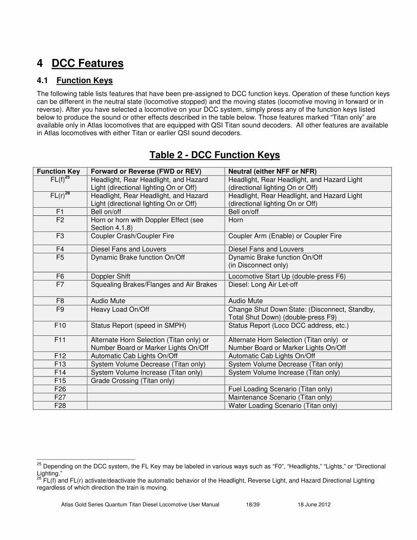
The following table lists features that have been pre-assigned to DCC function keys. Operation of these function keys can be different in the neutral state (locomotive stopped) and the moving states (locomotive moving in forward or in reverse). After you have selected a locomotive on your DCC system, simply press any of the function keys listed below to produce the sound or other effects described in the table below. Those features marked “Titan only” are available only in Atlas locomotives that are equipped with QSI Titan sound decoders. All other features are available in Atlas locomotives with either Titan or earlier QSI sound decoders.
Table 2 - DCC Function Keys
Function Key Forward or Reverse (FWD or REV) Neutral (either NFF or NFR)
FL(f)25
Headlight, Rear Headlight, and Hazard Light (directional lighting On or Off)
Headlight, Rear Headlight, and Hazard Light (directional lighting On or Off)
FL(r)26
Headlight, Rear Headlight, and Hazard Light (directional lighting On or Off)
Headlight, Rear Headlight, and Hazard Light (directional lighting On or Off)
F1 Bell on/off Bell on/off
F2 Horn or horn with Doppler Effect (see Section 4.1.8)
Horn
F3 Coupler Crash/Coupler Fire Coupler Arm (Enable) or Coupler Fire
F4 Diesel Fans and Louvers Diesel Fans and Louvers
F5 Dynamic Brake function On/Off Dynamic Brake function On/Off (in Disconnect only)
F6 Doppler Shift Locomotive Start Up (double-press F6)
F7 Squealing Brakes/Flanges and Air Brakes Diesel: Long Air Let-off
F8 Audio Mute Audio Mute
F9 Heavy Load On/Off Change Shut Down State: (Disconnect, Standby,
Total Shut Down) (double-press F9)
F10 Status Report (speed in SMPH) Status Report (Loco DCC address, etc.)
F11 Alternate Horn Selection (Titan only) or Number Board or Marker Lights On/Off
Alternate Horn Selection (Titan only) or Number Board or Marker Lights On/Off
F12 Automatic Cab Lights On/Off Automatic Cab Lights On/Off
F13 System Volume Decrease (Titan only) System Volume Decrease (Titan only)
F14 System Volume Increase (Titan only) System Volume Increase (Titan only)
F15 Grade Crossing (Titan only)
F26 Fuel Loading Scenario (Titan only)
F27 Maintenance Scenario (Titan only)
F28 Water Loading Scenario (Titan only)
25
Depending on the DCC system, the FL Key may be labeled in various ways such as “F0”, “Headlights,” “Lights,” or “Directional Lighting.” 26
FL(f) and FL(r) activate/deactivate the automatic behavior of the Headlight, Reverse Light, and Hazard Directional Lighting regardless of which direction the train is moving.
Atlas Gold Series Quantum Titan Diesel Locomotive User Manual 19/39 18 June 2012
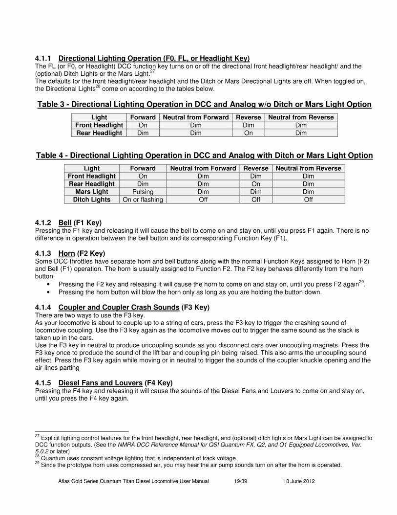
4.1.1 Directional Lighting Operation (F0, FL, or Headlight Key) The FL (or F0, or Headlight) DCC function key turns on or off the directional front headlight/rear headlight/ and the (optional) Ditch Lights or the Mars Light.
27
The defaults for the front headlight/rear headlight and the Ditch or Mars Directional Lights are off. When toggled on, the Directional Lights
28 come on according to the tables below.
Table 3 - Directional Lighting Operation in DCC and Analog w/o Ditch or Mars Light Option
Light Forward Neutral from Forward Reverse Neutral from Reverse
Front Headlight On Dim Dim Dim Rear Headlight Dim Dim On Dim
Table 4 - Directional Lighting Operation in DCC and Analog with Ditch or Mars Light Option
Light Forward Neutral from Forward Reverse Neutral from Reverse
Front Headlight On Dim Dim Dim Rear Headlight Dim Dim On Dim
Mars Light Pulsing Dim Dim Dim Ditch Lights On or flashing Off Off Off
4.1.2 Bell (F1 Key) Pressing the F1 key and releasing it will cause the bell to come on and stay on, until you press F1 again. There is no difference in operation between the bell button and its corresponding Function Key (F1).
4.1.3 Horn (F2 Key) Some DCC throttles have separate horn and bell buttons along with the normal Function Keys assigned to Horn (F2) and Bell (F1) operation. The horn is usually assigned to Function F2. The F2 key behaves differently from the horn button.
• Pressing the F2 key and releasing it will cause the horn to come on and stay on, until you press F2 again29
.
• Pressing the horn button will blow the horn only as long as you are holding the button down.
4.1.4 Coupler and Coupler Crash Sounds (F3 Key) There are two ways to use the F3 key. As your locomotive is about to couple up to a string of cars, press the F3 key to trigger the crashing sound of locomotive coupling. Use the F3 key again as the locomotive moves out to trigger the same sound as the slack is taken up in the cars. Use the F3 key in neutral to produce uncoupling sounds as you disconnect cars over uncoupling magnets. Press the F3 key once to produce the sound of the lift bar and coupling pin being raised. This also arms the uncoupling sound effect. Press the F3 key again while moving or in neutral to trigger the sounds of the coupler knuckle opening and the air-lines parting
4.1.5 Diesel Fans and Louvers (F4 Key) Pressing the F4 key and releasing it will cause the sounds of the Diesel Fans and Louvers to come on and stay on, until you press the F4 key again.
27
Explicit lighting control features for the front headlight, rear headlight, and (optional) ditch lights or Mars Light can be assigned to DCC function outputs. (See the NMRA DCC Reference Manual for QSI Quantum FX, Q2, and Q1 Equipped Locomotives, Ver. 5.0.2 or later) 28
Quantum uses constant voltage lighting that is independent of track voltage. 29
Since the prototype horn uses compressed air, you may hear the air pump sounds turn on after the horn is operated.
Atlas Gold Series Quantum Titan Diesel Locomotive User Manual 20/39 18 June 2012
4.1.6 Sound-of-Power™ Your diesel locomotive will produce labored diesel engine sounds under acceleration and lighter diesel engine sounds under deceleration, but only if CV3 or CV23 and CV4 or CV24 are set to non-zero positive values. The level of labored sounds is proportional to the values for these four CV’s and to how much the DCC throttle is increased or decreased.
Diesel Engine RPM: Quantum has all eight of the diesel engine throttle “notches” that are found on prototype locomotives. As you increase the throttle, you will hear the RPM’s increase for every increase in ten speed steps (at the 128 speed step setting). Idle is considered Notch 1 and occurs for speed step 0. Notch 2 ranges from 1 to 10, Notch 3 from 11 to 20, Notch 4 from 21 to 30, etc. If your DCC system has an option to increment or decrement your throttle setting by ten speed steps, it is very easy and predicable to set your notch value.
4.1.7 Dynamic Brakes (F5 Key) A prototype diesel locomotive usually has Dynamic Brakes that cause the train to slow down by using the traction motors in generator (rather than the normal motor) mode. This technique helps dissipate the energy of a moving train by converting it to electrical power, which is then applied to a large air-cooled resistor load in the locomotive.
• Pressing the F5 key in Forward or Reverse will set the locomotive diesel engine sounds to idle at the lowest Sound of Power setting and turn on the powerful Dynamic Brake Cooling Fans.
• Pressing the F5 key in neutral will turn on the Dynamic Brake Fans while diesel engine sounds remain at idle. The Dynamic Brake function automatically turns off when entering or leaving neutral, the speed of the locomotive drops below 7 smph
30, or the throttle is turned up. Dynamic Brakes cannot be turned on in Forward or Reverse unless
the locomotive is traveling over 8 smph. Note: In contrast to Air Brakes (F7), Dynamic Brakes do not increase the deceleration rate specified by CV4 and CV24.
4.1.8 Doppler Effect Operation (single-press F6 Key) With DCC, you can trigger the Doppler Effect by quickly interrupting the horn signal in the same way described under Analog Operation. Alternatively, you may use the Function Key (F6) dedicated to the Doppler Effect. Start the horn and/or bell by pressing and releasing their function keys
31.
Press F6 once to hear the Doppler shift. A few seconds after the horn button is turned off with the F2 key, the diesel engine sounds will return to normal
32.
4.1.9 Start Up (double-press F6 Key) If your Atlas sound-equipped diesel locomotive is in any stage of Shut Down, you can return your locomotive to normal operation by double-pressing the F6 Key. Start Up will be different for each stage of Shut Down, but a locomotive in any stage of Shut Down will start up with a long air release and then will enter normal operation.
• Start Up from Disconnect: If you double-press the F6 key in Disconnect; the diesel locomotive will produce a long air let-off; dynamic brakes will shut off (if on); and the locomotive will enter normal operation.
• Start Up from Standby: If you double-press the F6 key in Standby, the diesel locomotive will produce a long air let-off; Directional Lighting will turn on (if previously on); the diesel engine sound will change from the special Low Idle to regular Idle; and the locomotive will enter normal operation.
• Start Up from Total Shut Down: If you double-press the F6 key in Total Shut Down, the diesel locomotive will produce a long air let-off; you will hear the engineer’s door opening and closing; Cab Lights will come on (if available and loco is Normal or Lead Helper); Number Boards will come on (if available and loco is Normal or Lead Helper); Directional Lighting will turn on (if it was previously off). These actions are followed by sounds of the vents opening, the diesel engine starting up, the pumps starting up, and the locomotive entering normal operation. During the Start Up procedure, none of the function keys are active.
If the throttle is turned up from zero during any of the above Start Up procedures, the Start Up procedure will abort, and the locomotive will enter normal operation. Note: Whenever a Start Up command is sent, regardless of whether the locomotive is in Shut Down or operating normally, the Quantum System will automatically restore all Automatic Operations
30
Dynamic Brakes on prototype locomotives are less effective and seldom used at low speeds. 31
If you do not turn on either the horn or bell, the Doppler shift will still occur but will be less dramatic. 32
If the bell was on, it will shut off prior to sounds returning to normal.
Atlas Gold Series Quantum Titan Diesel Locomotive User Manual 21/39 18 June 2012
4.1.10 Squealing Brake and Flange Sounds (F7 Key) Quantum provides automatic brake squeal as a locomotive slows to a stop. The operator can also control squealing sounds for continuous and variable brake sounds for protracted stops or to simulate the sounds of squealing wheel flanges on curved track. Squealing Brakes come on automatically when the speed is reduced from high-speed travel (over 40 smph) to a speed less than 20 smph. Pressing the F7 key when the locomotive is moving at any speed will manually activate Squealing Brake sounds, and repeated pressings while the Squealing Brake sounds are occurring will continue the sounds uninterrupted. Note: If you slow the locomotive too quickly, the brake sounds will terminate abruptly when the locomotive stops and enters neutral. Note: If you lower your throttle to speed step 0 on a moving locomotive, the F7 key will apply Air Brakes as long as the locomotive continues moving. See the next section.
4.1.11 Air Brakes (F7 Key) Quantum provides automatic brake squeal as a locomotive slows to a stop. If you have selected any non-zero deceleration inertia or momentum value in CV4 and/or CV24, the F7 key can be used to apply brakes to stop the locomotive more quickly than it would normally stop from the inertia settings
33. To use Air Brakes:
• Turn the throttle down to speed step 0 on a moving locomotive; this enables the F7 key to act as a brake.
• Press the F7 key. Hear a brief brake squeal sound and air being released from the brake lines continually. The longer the air is released, the greater the braking action.
• Press the F7 key again to stop the air release. The train will continue to slow at the last braking value.
• If you want to apply more braking, press the F7 key again to release more air. When you reach the desired amount of braking, press F7 again to stop the air release.
Note: If you continue to release air (for over 24 seconds total), all the pressure will be released and the brakes will be on full; you will hear no further air release sounds. Turn up the throttle to any value above 0 to release the brakes; this action returns the locomotive’s deceleration to a value determined by the sum of CV4 and CV24. Note: If the locomotive is in Neutral when the F7 key is pressed, a long air release sound simulates setting the brakes. However, no braking effect is activated
34.
Note: If the throttle is set to any speed step except 0, air brakes are not enabled; instead the F7 key will now manually activate squealing brake/flange sounds but will not affect the locomotive’s deceleration.
4.1.12 Mute (F8 Key) The Quantum System allows you to reduce the System Volume to a lower level or increase it back to its original setting using the F8 function key. This capability is useful when you need to reduce the sound to engage in a conversation or to answer the phone. If you have many trains operating at once, you can reduce the volume on all those that are running in the background of the layout and increase the volume of the closest locomotive. The Mute feature changes the sound gradually over a second or two, which allows the sound to increase or decrease realistically as the locomotive approaches or recedes from the observer. Press the F8 key in Neutral or Forward/Reverse to gradually decrease or increase the locomotive’s volume. Note: Mute state is not maintained if power is turned off and back on; the locomotive will return to full volume setting. Note: Mute volume can be programmed in CV51.1.
4.1.13 Heavy Load (single-press F9 key) If Heavy Load is applied while the train is moving; it maintains the train at a steady speed while allowing you to have control over the sound effects of a working locomotive. Under Heavy Load, changing the throttle will have little effect on the locomotive’s speed. Instead, you can use the throttle to control your locomotive’s laboring Sound-of-Power sound effects. When you approach a grade under Heavy Load, increase the throttle and hear the locomotive work hard with heavy laboring sounds. When the locomotive goes down a grade, reduce the throttle to diminish the locomotive’s laboring sounds. You can control how hard the locomotive works by changing how much the throttle is increased or decreased from its initial position (where Heavy Load was turned on).
33
CV4 and CV24 determine the deceleration rate. Applying the brakes increases the deceleration rate temporarily. 34
If the brakes are set in neutral, turning up the throttle automatically releases the brakes.
Atlas Gold Series Quantum Titan Diesel Locomotive User Manual 22/39 18 June 2012
To turn Heavy Load on and off:
• Press F9 and hear one short hoot when Heavy Load is turned on
• Press F9 again and hear two short hoots when Heavy Load is turned off . Note: You can apply Heavy Load as soon as you start moving or wait until you are up to speed. Note: Return the throttle to its initial setting (where Heavy Load was turned on) to avoid acceleration or deceleration when Heavy Load is turned off. Note: Heavy Load can only be turned on or off in Forward or Reverse. If turned on, it will remain on in Neutral. If you want it off when you start out from Neutral, immediately do so when the throttle is turned up. Note: Heavy Load is automatically turned off when track power is turned off. Note: Heavy Load represents a train that would take over ten minutes to accelerate to full speed or to bring to a complete stop. It is independent of any inertia (or momentum) values set in CV3, CV4, CV23, or CV24. Note: Under RTC and Heavy Load, grades, voltage changes, tight curves, or other real loading effects will have little effect on the speed of the train. By contrast, under STC and Heavy Load, grades, loading, etc. will affect the train speed as it moves around the layout.
4.1.14 Three Stages of Diesel Locomotive Shut Down: (1) Disconnect, (2) Standby, (3) Total Shut Down (double-press F9 Key) Locomotive Shut Down has three distinct stages that you can control. Each stage is entered by double-pressing the F9 key
35.
Stage One: Disconnect Double press the F9 key in neutral to enter Disconnect. You will hear a long air let-off. To leave Disconnect, either double-press the F6 Start Up key, as described in Start Up (Section 4.1.9), or double-press the F9 key again to reach the next stage of Shut Down: Standby. If you double-press the F9 key in neutral, the motor drive will be disconnected. Once you hear the long air let-off, the DCC throttle can be moved up and down without the locomotive moving. As the throttle is moved up or down, you will hear the diesel engine in the locomotive rev up and down in proportion to the throttle setting. Note: You can also turn on the Dynamic Brakes (see description of Dynamic Brakes in Section 4.1.7) to create Sound–of-Power as the throttle is moved up and down. Engineers on prototype diesels use the Dynamic Brakes to load the diesel motor-generator to test its output and efficiency while the locomotive remains stationary.
Stage Two: Standby While in Disconnect, quickly press the F9 key twice to enter Standby. You will hear a long air let-off followed by a special “Low Idle” sound. The Directional Lighting system and optional ditch lights or Mars Light will shut down. The engine will remain disconnected, while the Air Pumps, automatic Cooling Fan Operation, Number Board Lights (if illuminated separately from the headlight), and Cab Lights will continue to operate. In Standby, the locomotive will not respond to the throttle or to most of the function keys
36. The three exceptions are the F6 Start-Up Function Key
(Section 4.1.9), the F8 Mute Key (Section 4.1.12), and the F10 Status Key (Section 4.1.15). To leave Standby, either double-press the F6 Start Up key, as described in the Start Up section, or double-press the F9 key again to reach the final stage of the Shut Down process, which is called Total Shut Down. Note: Standby is ideal for leaving your locomotive running on a siding. Besides hearing the low idle diesel engine sounds, the locomotive will not respond if you accidentally change the throttle setting or press a function key.
Stage Three: Total Shut Down If you double-press the F9 key while you are in Standby, you will enter Total Shut Down. As the locomotive goes into Total Shut Down, you will hear a long air let-off. To leave Total Shut Down, double-press the F6 key. If you double-press the F9 key while in Standby, you will hear a long air let-of, after which the locomotive will advance to Total Shut Down. The air pumps will turn off, followed by the number boards turning off, the sounds of the cooling
35
Double-pressing ensures that Shut Down stages are not entered or exited accidentally. Double-pressing is defined as two F9 commands sent within two seconds. Note that the F9 key may sometimes have to be pressed three times, due to the command station and locomotive having different initial states for F9. 36
Function keys will only produce a short air let-off.
Atlas Gold Series Quantum Titan Diesel Locomotive User Manual 23/39 18 June 2012
fans shutting off, the louvers closing, the diesel engine shutting down, and, finally, the Cab Lights shutting off. A few seconds later, you will hear the engineer’s door open and then shut. In Total Shut Down, the locomotive will not respond to the throttle or to the Function keys. The two exceptions are the F6 Start Up Function Key (described below) and the F10 Status Key (described below). If DCC track power is turned off at any stage of Shut Down (Disconnect, Standby or Total Shut Down) or during a Shut Down procedure, the locomotive will remember the last Shut Down stage in which it was prior to power going off, and the locomotive will power up in the same stage of Shut Down. If Start Up is initiated during any of the above Shut Down procedures, Shut Down will be aborted, and the locomotive will return to normal operation. Note: Total Shut Down allows the operator to take the locomotive “off line” (turn off sounds, lights, ignore throttle settings and function key commands) independent of the operating session; that is, the locomotive will still be “off line” when power is reapplied for the next operating session.
4.1.15 Status (F10 Key) The Quantum Titan system installed in Atlas sound-equipped locomotives provides verbal information about the locomotive’s current operating state when the locomotive is in neutral or about the locomotive’s current speed in scale miles per hour when the locomotive is moving. If you press the F10 key in Neutral, the locomotive will verbally report first its currently enabled long or short DCC address followed by its consist ID (if it has one), followed by its shut down state (Disconnect, Standby, or Shut Down), if any. Press the F10 key in Forward or Reverse; the locomotive will verbally report the locomotive’s speed in scale miles per hour. Note: When Status Report is activated, the locomotive’s sounds will reduce to one half their current volume settings during the verbal report and then return to normal volume when the report has ended.
4.1.16 Alternate Horn Selection (F11 Key) Some prototype diesel locomotives had two different air horns. The first horn worked best in areas where it was necessary for the sound to carry a long way, while the other horn was more useful in the city or fogy areas where it was easier to tell the location of the locomotive by its higher pitched sound. The Alternate Horn Selection key allows you to choose between two different Horn sounds. To use this feature:
• Press the Alternate Horn Selection key (F11) to select between the alternate Horn and the primary Horn. Hear a short hoot to indicate which horn has been selected.
• Operate the selected Horn with the F2 key. Note: The feedback hoots can be disabled or enabled by using CV51.2. (See Version 5.0.2 or later of the QSI DCC Reference Manual.) Note: Setting F11 to “1” selects the primary Horn. Setting F11 to “0” selects the alternate Horn. Note: This F11 Alternate Horn Selection feature is currently available only with Quantum Titan sound-decoders.
4.1.17 System Volume Decrease (F13 Key) and Increase (F14 Key) You can decrease the System Volume by 2 dB by pressing the F13 key. You can increase the System Volume by 2 dB by pressing the F14 key. Each time you press the F13 or F14 key you will hear a horn hoot at the new system volume. If the system volume is already at the maximum when you press the F14 key, the volume will not increase, and the locomotive will speak the word “Max”. Both F13 and F14 are inactive when the locomotive is in shutdown. Pressing F13/F14 decreases/increases the value of CV51.0 System Volume. Note: These F13/F14 features are currently available only with Quantum Titan sound-decoders.
4.1.18 Grade Crossing (F15 Key in Forward or Reverse) Prototype railroads use horn or whistle codes of long and short blasts for communication or warning signals. One of the most common is the code of two longs, a short, and a long horn signal to warn that the train is approaching a grade crossing. Although you can perform these signals with the Horn button, the Quantum Titan system has made this operation even more convenient. When the locomotive is in FWD or REV, press the F15 key once to trigger the grade crossing horn signal. If you press the Horn key during the Grade Crossing scenario, you will terminate this feature and take control of the Horn.
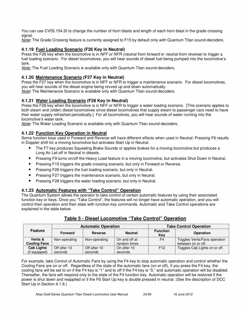
Atlas Gold Series Quantum Titan Diesel Locomotive User Manual 24/39 18 June 2012
You can use CV55.154.SI to change the number of horn blasts and length of each horn blast in the grade crossing signal. Note: The Grade Crossing feature is currently assigned to F15 by default only with Quantum Titan sound-decoders.
4.1.19 Fuel Loading Scenario (F26 Key in Neutral) Press the F26 key when the locomotive is in NFF or NFR (neutral from forward or neutral from reverse) to trigger a fuel loading scenario. For diesel locomotives, you will hear sounds of diesel fuel being pumped into the locomotive’s tank. Note: The Fuel Loading Scenario is available only with Quantum Titan sound-decoders.
4.1.20 Maintenance Scenario (F27 Key in Neutral) Press the F27 key when the locomotive is in NFF or NFR to trigger a maintenance scenario. For diesel locomotives, you will hear sounds of the diesel engine being revved up and down automatically. Note: The Maintenance Scenario is available only with Quantum Titan sound-decoders.
4.1.21 Water Loading Scenario (F28 Key in Neutral) Press the F28 key when the locomotive is in NFF or NFR to trigger a water loading scenario. [This scenario applies to both steam and (older) diesel locomotives since diesel locomotives that supply steam to passenger cars need to have their water supply refreshed periodically.] For all locomotives, you will hear sounds of water running into the locomotive’s water tank. Note: The Water Loading Scenario is available only with Quantum Titan sound-decoders.
4.1.22 Function Key Operation in Neutral Some function keys used in Forward and Reverse will have different effects when used in Neutral: Pressing F6 results in Doppler shift for a moving locomotive but activates Start Up in Neutral.
• The F7 key produces Squealing Brake Sounds or applies brakes for a moving locomotive but produces a Long Air Let-off in Neutral in diesels.
• Pressing F9 turns on/off the Heavy Load feature in a moving locomotive, but activates Shut Down in Neutral.
• Pressing F15 triggers the grade crossing scenario, but only in Forward or Reverse.
• Pressing F26 triggers the fuel loading scenario, but only in Neutral.
• Pressing F27 triggers the maintenance scenario, but only in Neutral.
• Pressing F28 triggers the water loading scenario, but only in Neutral.
4.1.23 Automatic Features with “Take Control” Operation The Quantum System allows the operator to take control of certain automatic features by using their associated function key or keys. Once you “Take Control”, the features will no longer have automatic operation, and you will control their operation and their state with function key commands. Automatic and Take Control operations are explained in the table below.
Table 5 - Diesel Locomotive “Take Control” Operation
Feature Automatic Operation Take Control Operation
Forward Reverse Neutral Function
Key Operation
Vents & Cooling Fans
Non-operating Non-operating On and off at random times
F4 Toggles Vents/Fans operation between on or off.
Cab Lights (if equipped)
Off after 10 seconds
Off after 10 seconds
On after 10 seconds
F12 Toggles Cab Lights on or off.
For example, take Control of Automatic Fans by using the F4 key to stop automatic operation and control whether the Cooling Fans are on or off. Regardless of the state of the automatic fans (on or off), if you press the F4 key, the cooling fans will be set to on if the F4 key is “1” and to off if the F4 key is “0,” and automatic operation will be disabled. Thereafter, the fans will respond only to the state of the F4 function key. Automatic operation will be restored if the power is shut down and reapplied or if the F6 Start Up key is double pressed in neutral. (See the description of DCC Start Up in Section 4.1.9.)
Atlas Gold Series Quantum Titan Diesel Locomotive User Manual 25/39 18 June 2012
4.2 DCC Programming Although most DCC systems currently available are capable of programming non-sound locomotives in either Service Mode (on the program track) or in Operations Mode (on the main line), many current DCC systems do not provide sufficient power to the program track to program sound-equipped locomotives. (This comment applies not just to Atlas Gold Series locomotives with QSI sound-decoders, but also to almost all sound-equipped locomotives with any manufacturer’s sound-decoder.) However, since there are a few DCC systems that do provide enough power to the program track to program sound-equipped locomotives in Service Mode, Atlas recommends that you first try to program your Gold Series locomotive in Service mode. If it works, you don’t need to do anything. If it does not, you have three choices:
• Check with the manufacturer of your DCC system; some companies will give you a free upgrade.
• Install a program track booster (NOT the same as a standard DCC system booster) between the program track output of your DCC system and your program track). See Section 6.3, Program Track Operation.
• Program on the main line in Operations Mode (Ops Mode). This third choice is often the best one, especially because of the verbal-announcement features of QSI sound-decoders. (See Sections 4.2.9 and 4.2.10.)
4.2.1 Changing the System Volume Electronically (CV51.0) You can change the volume either manually, as described in Section 6.1.2 Special Operation and Troubleshooting, or electronically using QSI CV51.0 in DCC
37. To change the volume in Service or Operations Mode, do the following:
• Set CV49 to 038
.
• Enter the desired System Volume in CV51. The System Volume can be set to any value between 0 (no
sound) and 127 (maximum volume). The default System Volume is 127. Note: In Operations Mode, when you change the System Volume, you will immediately hear the new System Volume.
4.2.2 Changing the Mute Volume Electronically (CV51.1) To change the Mute Volume in Service or Ops Mode, do the following:
• Set CV49 to 1.
• Enter the desired Mute Volume in CV51. The Mute Volume can be set to any value between 0 (no sound) and
63 (maximum volume). The default Mute Volume is 0. Note: In Ops Mode, when the locomotive is muted and you change the Mute Volume, you will immediately hear the new Mute Volume. Note: The Mute Volume level will be the smaller of either the Mute Volume setting or one half the current System Volume. In other words, the Mute Volume will never be more than one half the System Volume.
4.2.3 Enable/Disable Horn-Triggered-Doppler Shift (CV51.2)
• Set CV49 to 2.
• Set CV51 to 0 to disable Horn-Triggered-Doppler; set CV51 to 1 to enable Horn-Triggered-Doppler.
37
System Volume changes in DCC also apply to Analog and vice-versa. 38
You will hear the value 0 you entered for CV49 spoken out (Ops Mode Only).
Atlas Gold Series Quantum Titan Diesel Locomotive User Manual 26/39 18 June 2012
4.2.4 Enable/Disable Automatic Horn Warning Signals (CV51.20) You can use CV51.20 to enable (or disable) the following automatic horn warning signals that can be generated by the Quantum Titan sound decoder. This scenario imitates the actions required of a prototype locomotive engineer when he starts and stops his locomotive.
• Two short horn blasts when the locomotive first starts to move in FWD,
• Three short horn blasts when the locomotive first starts to move in REV,
• One short horn blast when the locomotive comes to a stop. To enable or disable these horn warning signals, perform the following steps:
• Set CV49 to 20.
• Set CV51 to 0 to disable all Horn Warning Signals, or set CV51 to 17 to enable all three of the Horn Warning Signals listed above.
If you want to enable a different horn warning scenario from those specified above, please refer to the definition of CV51.20 in the NMRA DCC Reference Manual for QSI Quantum FX, Q2, and Q1 Equipped Locomotives, Ver. 5.0.2 (or later). If you want to modify the timing, duration, and/or number of horn blasts in a Horn Warning Signal scenario, please refer to the definition of CV120.PI.SI
39 in this same reference manual.
Note: This Automatic Horn Warning Signals feature is available only with Quantum Titan sound-decoders.
39
PI stands for Primary Index; SI stands for Secondary Index. Refer to Sections 5.1 to 5.3 in the QSI DCC Reference Manual (pages 89 to 94 in Version 5.0.2) for an explanation of the Indexed CVs used in QSI sound-decoders.

Atlas Gold Series Quantum Titan Diesel Locomotive User Manual 27/39 18 June 2012
4.2.5 Changing Individual Sound Volumes (CV52.X40) To change the volume of individual sounds listed in the table below, do the following steps
41:
• Set CV49 to the Primary Index for the individual sound whose volume you wish to change from the table below.
• Enter the desired Volume level in CV52 as follows: “0” = No sound, “1 – 15” sets volume from the lowest level at “1” to the highest at “15”, with the volume levels changing in 2 dB increments.
Note: Normally, the default volume level for each type of sound is 11.
Table 6 - Using an Indexed CV to Change the Volume of an Individual Sound
40
‘X’ refers to the value in column 1 of the table, i.e., the Primary Index number that will be entered into CV49. 41
Setting any Individual Feature Volume in DCC will also apply to Analog and vice-versa. 42
Future feature, not currently available in Atlas Gold Series locomotives
Individual Sound Volume CV49 Value
CV52 Value
Corresponding Indexed CV
Resulting Volume
Horn Volume 0 0-15 52.0 0= Minimum Volume. 15= Maximum Volume
Bell Volume 8 0-15 52.8 0= Minimum Volume, 15= Maximum Volume
Diesel engine Volume 10 0-15 52.10 0= Minimum Volume, 15= Maximum Volume
Diesel engine 2 Volume42
11 0-15 52.11 0= Minimum Volume, 15= Maximum Volume
Turbocharger Volume 14 0-15 52.14 0= Minimum Volume, 15= Maximum Volume
Air Pump Volume 16 0-15 52.16 0= Minimum Volume, 15= Maximum Volume
Cooling Fans Volume 19 0-15 52.19 0= Minimum Volume, 15= Maximum Volume
Long Air Let-off Volume 21 0-15 52.21 0= Minimum Volume, 15= Maximum Volume
Short Air Let-off Volume 22 0-15 52.22 0= Minimum Volume, 15= Maximum Volume
Squealing Brakes Volume 24 0-15 52.24 0= Minimum Volume, 15= Maximum Volume
Generator Volume 26 0-15 52.26 0= Minimum Volume, 15= Maximum Volume
Dynamic Brakes Fan Volume 28 0-15 52.28 0= Minimum Volume, 15= Maximum Volume
Splitter Valve Volume 29 0-15 52.29 0= Minimum Volume, 15= Maximum Volume
Coupler Volume 34 0-15 52.34 0= Minimum Volume, 15= Maximum Volume
Air Brakes Volume 37 0-15 52.37 0= Minimum Volume, 15= Maximum Volume
Alternate Horn Volume 40 0-15 52.40 0= Minimum Volume, 15= Maximum Volume
User Sound Effect Volume 46 0-15 52.46 0= Minimum Volume, 15= Maximum Volume
Crew Talk Volume42
52 0-15 52.52 0= Minimum Volume, 15= Maximum Volume
Water Loading Volume 53 0-15 52.53 0= Minimum Volume, 15= Maximum Volume
Fuel Loading Volume 55 0-15 52.55 0= Minimum Volume, 15= Maximum Volume
Maintenance Volume 56 0-15 52.56 0= Minimum Volume, 15= Maximum Volume
Diesel engine rod-knock (low RPM) 62 0-15 52.62 0= Minimum Volume, 15= Maximum Volume
Diesel engine rod-knock (high RPM) 65 0-15 52.65 0= Minimum Volume, 15= Maximum Volume
Atlas Gold Series Quantum Titan Diesel Locomotive User Manual 28/39 18 June 2012
4.2.6 Selecting Standard Throttle Control™ or Regulated Throttle Control™ (CV56.4)
The differences between Standard Throttle Control (STC) and Regulated Throttle Control (RTC) are explained in
Section 3.643
. Follow the directions below to convert between RTC and STC when using DCC.
• Set CV49 to 4,
• Set CV56 to 0 for Standard Throttle Control or to 1 for Regulated Throttle Control.
Note: The default is Regulated Throttle Control.
Note: CV2, CV3, CV4, CV5 and speed tables apply to both Standard and Regulated Throttle Control.
.
4.2.7 Reset All44 CV’s to their Factory Default Values (CV56.128.255)
• Set CV49 to 128,
• Set CV50 to 255.
• Set CV56 to 11345
. In Ops Mode, you will hear “Reset” when reset is completed Note: This reset does not affect any Analog settings, except for volumes. Note: Atlas strongly recommends that you reset your locomotive using the magnetic wand (Section 6.1.1) rather than by this method.
4.2.8 Programming a New DCC Address for Your Locomotive The decoders in DCC locomotives normally come from the factory set to use the short address “3.” However, in order to control independently multiple locomotives on the same track at the same time, it is necessary that each of these locomotives have a different address. Most model railroaders pick as an address the road number printed on the side of the locomotive’s cab. Quite frequently, the road number on the side of the cab is a 3- or 4-digit number, which is treated as a Long (or 4-digit) Address in DCC.
Most DCC systems allow you to change the short (range is 1-127 for most DCC systems) or the long address in either of two places:
• On a special section of track that is not connected in any way to your layout and is called the Program Track. (In DCC terminology, programming locomotives on the Program Track is called Service Mode Programming.)
• Anywhere on your layout trackage. [In DCC terminology, programming a locomotive on your layout is called either Programming on the Main (POM) or Operations Mode (Ops Mode) Programming.]
Many DCC systems cannot supply enough power to the program track to read and write the CVs of sound-equipped locomotives. This problem may normally be solved by installing a Program Track Booster between the program track output of your DCC system and the program track (See Section 6.3). However, Atlas recommends that you use Operations Mode (Ops Mode) programming to change the address of your Gold Series locomotive, provided that your DCC system allows you to program 4-digit addresses on the main line (most DCC systems do). The following table shows some DCC systems commonly sold in North America that do and do not support direct 4-digit address programming on the main line. For those (relatively few) DCC systems that do NOT support Ops Mode address programming, a reference is given to one of three alternate programming procedures (defined later in this section). For all other DCC systems, use the programming procedure in Section 4.2.8.1.
43
STC and RTC operate in a similar fashion in Analog and in DCC. 44
Consult the Quantum Titan DCC Reference Manual (Version 5.0.2) to learn how to reset different groups of CV’s. 45
“113” is QSI’s Manufacturer’s ID Number, as assigned by the NMRA.
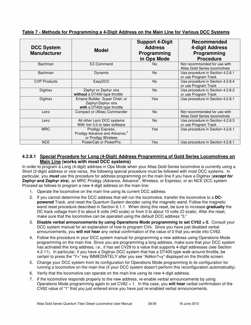
Atlas Gold Series Quantum Titan Diesel Locomotive User Manual 29/39 18 June 2012
Table 7 - Methods for Programming a 4-Digit Address on the Main Line for Various DCC Systems
DCC System Manufacturer
Model
Support 4-Digit Address
Programming in Ops Mode
Recommended 4-digit Address Programming
Procedure Bachman EZ-Command No Not recommended for use with
Atlas Gold Series locomotives
Bachman Dynamis No Use procedure in Section 4.2.8.1 or use Program Track
CVP Products EasyDCC No Use procedure in Section 4.2.8.4 or use Program Track
Digitrax Zephyr or Zephyr xtra without a DT400-type throttle
No Use procedure in Section 4.2.8.2 or use Program Track
Digitrax Empire Builder, Super Chief, or Zephyr/Zephyr xtra
with a DT400-type throttle
Yes Use procedure in Section 4.2.8.1
Lenz Compact or (Atlas) Commander No Not recommended for use with Atlas Gold Series locomotives
Lenz All other Lenz DCC systems With Ver 3.0 or later software
No Use procedure in Section 4.2.8.3 or use Program Track
MRC Prodigy Express, Prodigy Advance and Advance,
2
or Prodigy Wireless
Yes Use procedure in Section 4.2.8.1
NCE PowerCab or PowerPro Yes Use procedure in Section 4.2.8.1
4.2.8.1 Special Procedure for Long (4-Digit) Address Programming of Gold Series Locomotives on Main Line (works with most DCC systems)
In order to program a Long (4-digit) address in Ops Mode when your Atlas Gold Series locomotive is currently using a Short (2-digit) address or vice versa,
the following special procedure must be followed with most DCC systems. In
particular, you must use this procedure for address programming on the main line if you have a Digitrax (except for Zephyr and Zephyr xtra), an MRC Prodigy (Advance, Advance
2, Wireless, or Express), or an NCE DCC system.
Proceed as follows to program a new 4-digit address on the main line:
1. Operate the locomotive on the main line using its current DCC address
2. If you cannot determine the DCC address that will run the locomotive, transfer the locomotive to a DC-powered Track, and reset the Quantum System decoder using the magnetic wand. Follow the magnetic wand reset procedure described in Section 6.1.1. When doing this reset, be sure to increase gradually the DC track voltage from 0 to about 8 volts (HO scale) or from 0 to about 10 volts (O scale). After the reset, make sure that the locomotive can be operated using the default DCC address “3.”
3. Disable verbal announcements by using Operations Mode programming to set CV62 = 0. Consult your DCC system manual for an explanation of how to program CVs. Since you have just disabled verbal announcements, you will not hear any verbal confirmation of the value of 0 that you wrote into CV62.
4. Follow the procedure in your DCC system manual for programming a new address using Operations Mode programming on the main line. Since you are programming a long address, make sure that your DCC system has activated this long address, i.e., it has set CV29 to a value that supports 4-digit addresses (see Section 4.2.11). In particular, if you have a Digitrax DCC system that has a DT400-type walk-around throttle, be certain to press the “Y+” key IMMEDIATELY after you see “Ad4on?=y” displayed on the throttle screen.
5. Change your DCC system from its configuration for Operations Mode programming to its configuration for running a locomotive on the main line (if your DCC system doesn’t perform this reconfiguration automatically).
6. Verify that the locomotive can operate on the main line using its new 4-digit address.
7. If the locomotive responds properly to the new address, re-enable verbal announcements by using Operations Mode programming again to set CV62 = 1. In this case, you will hear verbal confirmation of the CV62 value of “1” that you just entered since you have just re-enabled verbal announcements.
Atlas Gold Series Quantum Titan Diesel Locomotive User Manual 30/39 18 June 2012
4.2.8.2 Special Procedure for Long (4-Digit) Address Programming on Main Line with Digitrax Zephyr or Zephyr xtra DCC Systems
If you have a DT400/DT402 throttle plugged into your Zephyr or Zephyr xtra DCC system, you do not need to use the procedure described in this section. Instead use the procedure described in the previous section (Section 4.2.8.1).
1. Put your locomotive on the main track and run it on DCC using address 3, or whatever other address you have programmed into the locomotive. If you can’t determine the address, reset the locomotive with the magnetic wand on a DC-POWERED track, using the procedure described in Section 6.1.1. Then test run the locomotive on DCC using the main track and DCC address 3.
2. Since your locomotive has a QSI sound decoder, keep the locomotive on the main line and use Operations Mode programming to set CV62 = 0. This operation maximizes the probability that CV29 will be set to its typical 4-digit address value of CV29 = 38 in Step 8 below. This step is not always needed, but it is impossible to tell if the step is necessary without going through the entire programming sequence.
3. Turn Option Switch 7 “on” so that you can use Digitrax’s Blast Mode programming feature: a. Press the PROG key on your Zephyr or Zephyr xtra DCC system. b. Press the SWITCH key. c. Use the keyboard to enter 07, which is the number of the Option Switch that you need to turn on d. Press the c/- key to turn Option Switch 07 “on.” e. Press the EXIT key when you are finished setting Option Switch 7.
4. If you took the locomotive to be programmed off the main track, put it back on the track. If DCC track power is off, turn it back on using the POWER key on the Zephyr or Zephyr xtra. Make sure that the locomotive to be programmed still runs on DCC using address 3 (or whatever other address you have programmed into it).
5. Keep pressing the PROG key until you see PAGE on the Zephyr’s or Zephyr xtra’s display. 6. Keep pressing the LOCO key until you see AD4 on the Zephyr’s or Zephyr xtra’s display. 7. Use the keyboard to enter the 4-digit address that you wish to program (e.g., 1234 or any other address
between 128 and 9983) 8. When you have finished entering the 4-digit address, write this new address into your locomotive by pressing
the CV-WR key. Do not be surprised if the locomotive leaps forward when the programming takes place. This movement doesn’t always happen, but it can.
9. To exit Blast Mode programming on the main line, press the EXIT key on your Zephyr or Zephyr xtra. 10. To run the locomotive whose address you entered in Step 7, press the LOCO key; re-enter the address you
entered in Step 7 by using the Zephyr or Zephyr xtra keyboard; and press the LOCO key again. 11. Verify that the locomotive runs using its new address. 12. If the locomotive did not run in Step 11 when you used its new address,
a. Turn off DCC track power and move the locomotive that you are trying to program from the main line to the program track.
b. Using Direct Mode programming (or whatever other type of programming your decoder requires), read the values of CV29 and AD4. For 4-digit addresses, the value of CV29 should be 38 and AD4 should be the address that you entered in Step 7.
c. If either or both of these values are not correct, change it (them). You may make any necessary changes in Direct Mode while the locomotive is on the program track.
13. Turn off Blast Mode programming by changing the setting of Option Switch 07 to “off.” a. Press the PROG key. b. Press the SWITCH key. c. Use the keyboard to enter 07, which is the number of the Option Switch that you need to turn off. d. Press the t/+ key to turn Option Switch 07 “off.” e. Press the EXIT key when you are finished setting Option Switch 7.
14. If your locomotive has a QSI sound decoder and you set CV62 = 0 in Step 2, put the locomotive back on the main line, run it briefly at its new 4-digit address, and configure the Zephyr or Zephyr Xtra for Operations Mode programming. Now change CV62 back to its default value of CV62 = 1.

Atlas Gold Series Quantum Titan Diesel Locomotive User Manual 31/39 18 June 2012
4.2.8.3 Special Procedures for Short or Long Address Programming for Lenz and Other DCC Systems that Do Not Normally Permit Address Programming on Main Line (CV56.129)
If you cannot program your Short or Long address in Service Mode and your Lenz (or other) DCC command station prevents you from setting either of these addresses in Ops Mode on the main line (using CV1, or CV17 and CV18), use one of the following two alternative procedures to program your locomotive’s address.
• Alternate Procedure for Programming Short Addresses in Ops Mode − Set CV49 to 129.
− Set CV50 to 1.
− Set CV56 to your short address (range 1–127 for most DCC systems). Hear the address spoken back.
− If necessary, set CV29 to 6 (which is the factory default) to enable your new short (2-digit) address.
• Alternate Procedure for Programming Long Addresses in Ops Mode − Determine the values of CV17 and CV18 that correspond to your locomotive’s 3- or 4-digit ID number
either by using one of the CV17/CV18 calculators available on the Internet, such as http://ruppweb.dyndns.org/xray/comp/decoder.htm
or else by following the instructions for calculating the values of CV17 and CV18 in the NMRA DCC Reference Manual for QSI Quantum
® FX, Q2, and Q1 Equipped Locomotives, (Version 5.0.2 or later).
− Set CV49 to 129.
− Set CV50 to 17.
− Set CV56 to the value for CV17 that you determined in Step 1.
− Set CV50 to 18.
− Set CV56 to the value for CV18 that you determined in Step 1.
− Set GV64 to 17. Hear the new full Long (3 or 4 digits) Address spoken out.
− Set CV29 to 3846
to allow operation with your new Long Address.
4.2.8.4 Special Procedures for Long Address Programming on the Main Line for CVP Products EasyDCC System
The EasyDCC system from CVP Products allows you to program on the main line the two CVs that hold a 4-digit address (CV17 and CV18), but it does not allow you to program the 4-digit address directly.
1. Determine the values of CV17 and CV18 that correspond to your locomotive’s 3- or 4-digit ID number either by using one of the CV17/CV18 calculators available on the internet such as
http://ruppweb.dyndns.org/xray/comp/decoder.htm or else by following the instructions for calculating the values of CV17 and CV18 in the NMRA DCC Reference Manual for QSI Quantum
® FX, Q2, and Q1 Equipped Locomotives, (Version 5.0.2 or later).
2. Make sure that verbal announcements (of CV values) are turned on (CV62 = 1). 3. Using Operations Mode Programming, program CV17 to the value that you determined in Step 1. Listen to
the value of CV17 that is spoken out by your locomotive. If it is correct, go to Step 4; if it is incorrect, repeat Step 3
4. Using Operations Mode Programming, program CV18 to the value that you determined in Step 1. Listen to the value of CV18 that is spoken out by your locomotive. If it is correct, go to Step 5; if it is incorrect, repeat Step 4.
5. Using Operations Mode Programming, program CV29 to the value 3847
. Listen to the value of CV18 that is spoken out by your locomotive. If it is correct, go to Step 6; if it is incorrect, repeat Step 5.
6. Verify that the address of your locomotive has been changed successfully changed by running it on the main line.
46 Entering “38” leaves the other configuration settings in CV29 at factory default values, but changes the ID to extended type. 47
If you wish to make any other changes to CV29 (see Section 4.2.11 for a list of the possible options for CV29), do not do so until you have verified that the address has been changed successfully.

Atlas Gold Series Quantum Titan Diesel Locomotive User Manual 32/39 18 June 2012
4.2.9 Disable/Enable Verbal Announcements (CV62) In Ops mode, the Quantum System will automatically announce the value of the CV that you entered.
• To disable, set CV62 to 048
;
• To enable, set CV62 to 1. Default is enabled. .
4.2.10 CV Inquiry with Verbal Feedback in Ops Mode (CV64)49 To inquire about the current value of any CV through Verbal Feedback in Ops Mode:
• Set CV64 to the number of the CV you wish to query.
• Hear the verbal message CV ‘X’ equals ‘Y’, where ‘X’ is the CV number and ‘Y’ is the value. If the CV has a Primary Index such as QSI CVnn.mm (where nn is the CV number and mm is the Primary Index),
• First set CV49 to mm
• Then set CV64 to nn. For example, if you want to inquire about the Bell Volume, which is CV52.8 (see Section Error! Reference source not found.), set CV49 to 8 and then set CV64 to 52. You will hear, “CV five two point eight equals ‘Y’ (where ‘Y’ is the current volume setting).
Note: If you enter either ‘17’ or ‘18’ into CV64, you will hear the full Long Address ID number spoken out.
4.2.11 Selecting a Value for CV29 CV29 is the most important of all the Configuration Variables in DCC. Each bit in CV29 controls some basic operational settings for DCC decoders, such as Extended (4-digit) Addressing, user-defined Speed Table enable, Power Source Conversion (operate on DC and DCC or only on DCC), Locomotive Direction, and others. The default value of CV29 is 6. The following table provides some of the more common values for CV29 and the features that these values support.
Table 8 - Available Features for Various Values of CV29
If You Want this Set of Features Write this Decimal
Value into
CV29
2- or 4- Digit
Addressing
Activate Alternate
Speed Table (CV67–CV94)
Locomotive
Operates On DC
Locomotive
Uses 28 or 128 Speed Steps
Normal
Direction of Locomotive
2 No No Yes Forward 2
2 No Yes Yes Forward 6
2 Yes No Yes Forward 18
2 Yes Yes Yes Forward 22
4 No No Yes Forward 34
4 No Yes Yes Forward 38
4 Yes No Yes Forward 50
4 Yes Yes Yes Forward 54
2 No No Yes Reversed 3
2 No Yes Yes Reversed 7
2 Yes No Yes Reversed 19
2 Yes Yes Yes Reversed 23
4 No No Yes Reversed 35
4 No Yes Yes Reversed 39
4 Yes No Yes Reversed 51
4 Yes Yes Yes Reversed 55
48 You will not hear “CV62 = 0”. 49
This option is not affected by CV62 (Disable/Enable Verbal Announcements).
Atlas Gold Series Quantum Titan Diesel Locomotive User Manual 33/39 18 June 2012
Two common values for CV29 that allow both DCC and DC operation are 6 (2-digit address) and 38 (4-digit address). For more information, download the NMRA DCC Reference Manual for QSI Quantum FX, Q2, and Q1 Equipped Locomotives, Version 5.0.2 or later. You can find this document, or a more recent version of it, on the QSI Solutions website
http://www.qsisolutions.com/
by clicking on “DOWNLOADS AND MANUALS,” going to the bottom of the webpage, and double-clicking on the first bullet item under the “General” heading. On the webpage, the document is under the heading “Full DCC Reference Manual for All QSI Decoders.”
5 Quantum System Sounds50 Air Brakes: When prototype train brakes are applied, air is released from the brake lines to reduce the pressure. The more the pressure is reduced, the greater the braking. You will hear a continual air release sound from the model locomotive as braking is continually increased. The longer the air is released, the quicker the model locomotive will slow down. Once all the pressure is released, the locomotive will continue at maximum braking, which can still result in a long stopping distance depending on your momentum/load settings. DCC and QARC
51 Only
Air Pumps: When a locomotive is sitting still, the pumps come on in a steady beat to replace the air lost from the brake air release or any other air-operated appliances. Once the pressure is up, the pumps run only occasionally to maintain the pressure. Diesel Air Pumps are operated directly from the engine and are quite noticeable when turned on in a non-moving locomotive. In Forward, you will hear the air pumps come on soon after the horn is operated to maintain the air pressure. Appliance Air Release: Compressed air is used on locomotives for operating various appliances. You will hear either a short air release or long air release at various times. Bell: Diesels and Electric locomotives, as well as larger steam locomotives, usually have pneumatically operated mechanical bells. Small steam locomotives often have hand-pulled bells. During turn-on in neutral, hear the pneumatic clapper gain greater throw with each stroke until it finally strikes the bell. During shut down in neutral, you will hear the bell fade out along with the short air release sound associated with turning this appliance off. Brake Squeal: You can hear the brakes squeal on prototype locomotives when the locomotive is moving slowly, and this noise can become particularly loud when the wheels are just about to stop turning. Listen at slow speeds for automatic brake squeal sounds and the final distinctive squealing sounds as the diesel locomotive slows to a stop. Cooling Fans: The enormous diesel engines and generators, which are enclosed in the diesel locomotive body, need ventilation in order to stay cool. All diesel locomotives have powerful cooling fans on the roof to draw outside air through louvers on the sides of the locomotive. The outside air is blown across large radiators. You will also hear the sounds of louvers opening before the fans start. When cooling fans shut down, you will hear the louvers close. Diesel Engine Rev: Quantum allows the diesel engines to be operated with all eight notches corresponding to the throttle notches used on the prototype. As the throttle is turned up, the diesel engine RPM will increase in fixed increments until the maximum RPM occurs at notch 8. Diesel Turbo: On modern diesels, turbo appliances are used to improve the engine’s horsepower by pumping air into the intake manifold under pressure. The power to operate the turbo comes from the diesel engine’s exhaust pressure, which causes the high-pitched whine of the turbo to lag the revving of the engine. Quantum systems use a
50
Not all features described here are included in every Atlas Gold Series locomotive. Consult the 4-page locomotive information booklet that came with your locomotive for a list of the features and sounds that apply to your particular locomotive. 51
QARC™ or Quantum Analog Remote Control™ uses special signals under Analog control to operate different Quantum features. With QARC, you can operate features that are otherwise available only in DCC. The Quantum Titan sound-decoder and the Quantum Engineer (Section 3.12) communicate with each other using QARC messages.
Atlas Gold Series Quantum Titan Diesel Locomotive User Manual 34/39 18 June 2012
separate sound record for the turbo to allow it to lag behind revving the engine up and to “hang” for a few seconds when the engine is revved down. Dynamic Brakes: Electric motors can act as motors or generators depending on whether they are using power or generating power. When used as generators, the traction motors are disconnected from taking power from the locomotive’s prime mover, and instead are connected to large resistor grids in the roof. By increasing the resistive load on the traction motors, the traction motors become harder to turn and act as brakes for the locomotive. The electric power generated by turning the traction motors is dissipated as heat by the resistor grid. These resistor arrays get quite hot and require cooling. When dynamic brakes are turned on in a Quantum-equipped diesel locomotive, the diesel engine sound drops to notch 1, and the Dynamic Brake cooling fan sounds come on. Since Dynamic Brakes are relatively ineffective a low speeds, the Dynamic brakes will shut off automatically below 8 smph. DCC and QARC Only Doppler Run-by: The engine sounds get louder as the train approaches, then immediately drop to a much lower pitch and lower volume as the train passes by. With a little practice you can change the pitch exactly when and where you want. Doppler shift is based on the speed of the locomotive, so the sounds change more dramatically when the locomotive is running faster. After the Doppler shift has occurred and the horn is no longer being blown, the bell shuts off automatically and locomotive sounds return to normal. Coupler: To give you the most authentic coupler sounds, QSI has identified three distinct types of coupler activity. The first is when the coupler is armed when you will hear the clanking sound of the coupler lift bar and coupler pin raising. The next is the sound of the coupler opening, along with the hiss of the air-lines parting. The third is when the locomotive couples up to its load of cars, and you hear the crash as the cars bunch together from the impact. DCC and QARC only Flanges: When a train enters a curve, the flanges on the wheels ride up on the inside of the rail and squeal. Recreate this squealing effect by pressing and releasing the Brake Squeal/Flanges button quickly and repeatedly as necessary. DCC and QARC only Horn: The Quantum System uses authentic locomotive sounds whenever possible. All Quantum horns are engineered by our sound experts to give you the most authentic effects. If you blow the horn briefly, you will produce a realistic short horn sound or “hoot”. Low Idle: Low Idle is used on prototype locomotives to maintain a warm and ready locomotive with a minimum of fuel consumption. The special Low Idle sound has a lower base throb and is less harsh than the normal idle.
6 Special Operation and Troubleshooting For a full description, see the Troubleshooting section in the latest Quantum DCC Reference Manual. You can find this document on the QSI Solutions website http://www.qsisolutions.com/ by clicking on “DOWNLOADS AND MANUALS,” going to the bottom of the webpage, and double-clicking on the first bullet item under the “General” heading. On the QSI Solutions webpage, the document is called “Full DCC Reference Manual for All QSI Decoders.” With some DCC systems, using the horn button to activate the horn and activating the F6 Doppler Key while this button is held down, will cause the horn to shut off instead of causing a Doppler shift effect. We have experienced intermittent and independent horn signal interruption with certain DCC systems, causing unexpected Doppler shifts. If this happens frequently, you may want to disable the Horn-Triggered-Doppler shift (CV51.2, see Section 4.2.3.)
6.1 Reed Switch Operation with the Magnetic Wand (Analog and DCC) Your Atlas sound-equipped locomotive is equipped with a special reed switch located directly underneath the top of the plastic diesel locomotive shell. This switch can be activated by the Magnetic Wand (enclosed) without having to disassemble the locomotive. The reed switch can be used either to reset the locomotive parameters to factory defaults or to change the overall volume of your sound system.
Atlas Gold Series Quantum Titan Diesel Locomotive User Manual 35/39 18 June 2012
6.1.1 Resetting your Locomotive to Factory Default Values Using the Magnetic Wand (resets all Analog and all DCC parameters) Resetting the firmware in the Titan sound-decoder to its factory-built configuration can resolve many problems that sometimes occur with firmware-controlled electronics. In fact, at Atlas we have found that at least 20 to 25 percent of the problems with Gold Series locomotives that we receive for repair can be resolved simply by resetting the sound decoder. Hence, the very first step you take to resolve a problem should always be to reset the Quantum Titan sound-decoder. There are two ways to reset the sound-decoder parameters (1) the DCC-only reset described in Section 4.2.7 that resets only the DCC CVs and (2) the magnetic wand reset described here that resets both DCC CVs and analog parameters. Since a number of parameters (e.g., sound volumes) are shared between DC and DCC operation, the magnetic wand reset does a better job of resetting the decoder to its original factory configuration. Hence, Atlas recommends resetting using the magnetic wand whether your locomotive is normally operated on DC or on DCC. The following items are needed in order to do a magnetic wand reset. Please note that it is essential to use conventional DC track power for this magnetic wand reset procedure to work properly. This procedure applies to all Atlas Gold Series locomotives, both HO and Two-Rail O-scale
1. Turn off all track power to your layout. 2. Place your Atlas Gold Series sound-equipped locomotive on a section of track that is powered by
conventional DC. 3. Locate the reed switch area on the top of the locomotive. The arrow in the photo of your Atlas Gold
Series locomotive that appears on page 3 of the 4-page locomotive information booklet (packed with the locomotive) points to the location on the top of the locomotive under which the reed switch is located.
4. Place the Magnetic Wand over the reed switch area on the top of the locomotive at the location determined in Step 3 and with the metal (shiny silver) part of the wand parallel to the ties of the track and on or just above the top of the locomotive. The magnet (the shiny silver cylinder) should be horizontal with one circular end pointing towards one side (side NOT end) of the locomotive and the other end pointing towards the other side. Keeping the wand in the small plastic bag in which it was shipped prevents possible marring or scratching of the locomotive.
5. Slowly and gradually apply conventional DC power to your track until the track voltage increases from 0 to approximately 8 to 10 volts. If the magnet is in the correct location (along the length of the locomotive and with the silver part parallel to the ties), the locomotive will not move, and there will be no sound until you hear “reset” spoken in Step 6 (below).
6. While continuing to hold the magnetic wand on or just above the top of the locomotive, keep increasing the track voltage slowly until you hear the word “reset” spoken from the locomotive.
7. Caution: if you don’t hear the word “reset” spoken, your locomotive has NOT been reset. 8. Pull the Magnetic Wand straight up (away from the locomotive) immediately after you hear “reset” so that
the manual volume adjustment procedure is not activated. This procedure works ONLY with those QSI-equipped locomotives that have a magnetic reed switch. Although all Gold Series Atlas HO and Gold Series Atlas O 2-rail locomotives have a magnetic reed switch, some QSI-equipped locomotives from other manufacturers have a jumper wire instead of a reed switch. If your locomotive has a jumper wire to trigger reset, refer to the manual included with your locomotive for reset instructions
ITEMS REQIRED FOR MAGNETIC WAND RESET 1. The Gold Series locomotive that you wish to reset 2. The magnetic wand (packed with your locomotive) 3. The 4-page locomotive information booklet (packed with your locomotive) that
shows (in a photo at the top of page 3) where to place the magnetic wand on the top of your locomotive
4. A section of track longer than your locomotive 5. A power pack with a Variable DC output 6. Wires to connect the power pack to the track
Atlas Gold Series Quantum Titan Diesel Locomotive User Manual 36/39 18 June 2012
6.1.2 Manual Volume Adjustment (Analog and DCC) 1. Locate the reed relay area on the top of the locomotive, as shown in the photograph on page 3 of the 4-
page locomotive information booklet that is included with your model. 2. Power up the locomotive and leave it in Neutral. Make sure that the bell is not turned on. 3. Place the silver part of the enclosed magnetic wand over the reed switch area on the top of the
locomotive52
(parallel to the ties and perpendicular to the rails) and wait as you hear the volume increase or decrease in incremental amounts as the horn hoots about every second. Move the wand away and again place it over the reed switch area to change the direction (louder or softer) of the volume change. Remove the wand when you reach the desired volume level.
Note: Volume can also be adjusted digitally using the programming methods described in the Analog and DCC programming sections of this manual.
6.1.3 Turn your Locomotive Off or On using the Magnetic Wand (Analog Only) Your locomotive can be selected (turned on) or deselected (turned off) using the Magnetic Wand. When the locomotive is deselected, it will remain unmoving and silent with lights off and will not respond to changes in track voltage or Analog horn or bell signals or programming commands.
1. To Shut Off a Locomotive: a. Enter neutral and turn on the bell. b. Place the Magnetic Wand over the reed switch area. The bell will shut off followed by the locomotive
shutting down and all lights turning off Note: You can turn off a locomotive in a consist even though it has been programmed as a Helper type with disabled bell and horn sound. Simply send the bell signal command. Even though the bell will not be heard, the Magnetic Wand will shut the locomotive down.
2. To Turn On a Locomotive: a. Make sure track power is applied. Place the Magnetic Wand over the reed switch area on the
locomotive. The lights will come of followed by startup sounds. The locomotive is now selected and will respond to track voltage and all bell and horn signals.
b. Using the Magnetic Wand makes it easy to turn locomotives off or on in Analog without the need for blocks. You can place locomotives on sidings and shut them off without having to switch power off in that track section. You can make up consists by bringing up each locomotive one at a time. After you couple each locomotive to the consist, shut it down with the Magnetic Wand. When all locomotives are in place, select each locomotive in turn with the Magnetic Wand until all locomotives are running. You can now operate the consist as a single unit. When you break up the consist, you first deselect all locomotives one at time and then select each one in turn as you disconnect and pull away from the consist.
6.2 High Voltage Circuit Breaker (Analog and DCC) Your locomotive is designed to operate on the normal DC track voltage supplied by most variable DC power packs and DCC systems. If the track voltage exceeds 21.5 volts peak, the motor drive circuit will automatically shut down, and the locomotive will coast to a stop. The Quantum System alerts you to the problem through a continuous series of horn hoots. This built in safety feature protects both the Quantum electronics and the motor from excessive voltage
53.
To restart your locomotive, reduce the track voltage until the hooting stops and the motors re-engage.
52 The wand does not need to touch the body. It can be held a reasonable distance from the top of the locomotive to prevent possible marring of the painted surface. 53 The high voltage circuit breaker will sometimes activate if the load (inertia or momentum) feature is used. Most power packs have substantial series resistance, which lowers the track voltage when the engine is drawing power. However, with a load setting, the engine does not require much power when it first starts moving. If the throttle is turned all the way up before the engine gains speed, the track voltage will be unusually high and can trigger the high voltage circuit breaker.
Atlas Gold Series Quantum Titan Diesel Locomotive User Manual 37/39 18 June 2012
6.3 Program Track Operation (DCC) This locomotive conforms to NMRA standards for program track operation. However, the Quantum sound system, like almost all other sound decoders, requires more current to operate than standard decoders and may not respond to the limited program track power available from many DCC systems. If you cannot program your Atlas Gold Series locomotive on the program track, you have two choices:
• Add a program track booster, such as the PowerPax from DCC Specialties or the PTB100 from Soundtraxx, between the program track output of your DCC system and the program track;
• All CV’s in your locomotive can be programmed on the main line in Ops Mode. If you don’t know the loco’s current address, you will have to reset it using the magnetic wand (Section 6.1.1) and then program it as loco #3.
6.4 Reasons Why Your Locomotive is Silent or Will Not Start (Analog and DCC) In case your locomotive remains silent after power up and turning the power off for 15 seconds does not return it to normal operation, try the following suggestions to bring your locomotive back to normal sound operation.
• Make sure the locomotive has not been Muted with the F8 Key.
• Check to see if your manual volume (using Magnetic Wand) or digital volume has been turned all the way down.
• You may have shut your locomotive down in DCC using the F9 key, which remains in effect in Analog or it has been shut down using the Magnetic Wand in Analog. Go back to DCC operation and start your locomotive with the F6 key
54. Once started, you can return to DC or DCC operation. Or use the Magnetic
Wand in Analog which selects and starts the locomotive if it has been shut down.
• If the above methods do not start your locomotive, reset your locomotive to factory default values using the magnetic wand, as described in Section 6.1.1.
54 It may take a couple of tries to get it started.

Atlas Gold Series Quantum Titan Diesel Locomotive User Manual 38/39 18 June 2012
Quantum Titan Features Available in Analog (DC) and DCC Operation
Sounds & Features Common to Analog & DCC
Analog Features* DCC Features*
Horn or hoot Bell with shut down and turn on effects Diesel Engine Diesel Turbo (optional) Automatic Cooling Fans Doppler Shift Brake or Flange Squeal Neutral Sounds Long Air Release Short Air Release Air Pumps Sound of Power™ Neutral State (Idle) Directional Lighting Bright Headlight Reverse Light (optional) Mars Light (optional) Number Board Lights (optional) Cab Lights (optional) Fuel Loading Scenario Water Loading Scenario Maintenance Scenario Manual Volume Control with Magnetic Wand Reset to Factory Default with Magnetic Wand
System Volume Programming Individual Sound Volume Control Regulated Throttle Control and locomotive Inertia Helper Type: (Normal) Normal loco, Lead Loco, Mid Helper, End Helper. Pusher. Direction: (Normal) Normal/Reversed Power Pack Programming V-Max (12v) V-Start (8.5v) Shut Down & Start Up with Magnetic Wand
QSI QARC™ Operation** (with QSI Quantum Engineer Controller™) Air Brakes Flanges Dynamic Brakes Engine ID’s. Consist ID’s. Coupler Sounds Diesel Extended Shut Down Extended Start Up Explicit Lighting Control Controllable Flange Squeal Load on/off toggle Fan on/off toggle Verbal Engine Status Grade Crossing Signal Audio Mute System Volume Control Plus additional features
F0 or FL light control F1-F28 Function Keys 14/28/126 speed steps (28) Coupler Sounds Air Brakes Dynamic Brakes Programming Modes Supported: Address Mode, Register Mode, Service Mode, Direct Mode, Ops Mode Long Form & Ops Mode Short Form
NMRA CV’s supported: 1 Primary Address 2 V-Start) 5 V-High) 6 V-Mid) 8 QSI MFG’s ID Number (113) 3-4,7, 11,17-25,29, 66-95 QSI CV’s supported: 49 Primary Index 50 Secondary Index 51 Sound Control 51.0 System Volume 51.1 Mute Volume 51.2 Doppler (Enable/disable) 51.20 Ready to Move Scenario (Enable/Disable) 52 Individual Sound Volume Control 53 Function Output Mapping 56 QSI Feature Configuration 56 QSI Configuration 56.128.n Reset 56.253 Version Build Information 62 Auto CV Verbal Feedback (enabled) 64 CV Inquiry Verbal Readout 115 Feature to Port Mapping 116 Individual Sound Balance Control 117 QSI Individual Sound Selection 118 Individual Sound Pitch Shift 120 Ready to Move Scenario
* Settings in parentheses indicate factory default ** QARC
55 Technology allows commands to be sent to locomotives under Analog control to operate different Quantum features.
With QARC technology, you can operate features that are otherwise available only in DCC plus features that are not yet available in DCC. The Quantum Engineer controllers are inexpensive accessories that employ the QARC system. They can be added to your existing power pack to operate additional features on your Quantum
56 equipped locomotive.
55
Quantum Analog Remote Control (QARC) Technology 56 Not all Quantum equipped locomotives contain QARC Technology.
Atlas Gold Series Quantum Titan Diesel Locomotive User Manual 39/39 18 June 2012
QSindustries, Inc. Software License Agreement 1. Grant of License: QSindustries, Inc. grants you, the owner, and the right to use the software that is included with your Quantum system only with the locomotive that you purchased. 2. Copyright: The software is owned by QSindustries, Inc. and is protected by United States copyright laws and international treaty provisions. Therefore, neither you nor anyone else may copy the software.
Proprietary Rights and Obligations The structure and organization of the Software/Firmware are the valuable properties of QSindustries, Inc. You will not make or have made, or permit to be made, any copies of the Hardware, Software/Firmware code, or any portions thereof. You are not to modify, adapt, translate, reverse engineer, de-compile, disassemble or create derivative works based on the Hardware or Software/Firmware. Trademarks shall be used in accordance with accepted trademark practice, including identification of trademark owner’s name. The Quantum Hardware, Software, and Firmware are covered by U.S. Patent No. 4,914,431; 5,184,048; 5,267,318; 5,394,068; 5,448,142; 5,633,985; 5,832,431; 5,896,017; 5,940,005; and US and Foreign patents pending.
No Other Rights QSindustries, Inc. retains ownership of the Quantum Hardware design and operating Software/Firmware code. Except as stated above, this agreement does not grant you any rights to intellectual property rights to the Quantum Software, Firmware or Hardware. The use of any trademarks as herein authorized does not give you any rights of ownership in that trademark. _____________________________________________________________________________________________ © 2012 All rights reserved. Information in this publication supersedes that in all previous published material. The contents and the product it describes are subject to change without notice. QSI is a registered trademark of QSindustries, Inc. Quantum, Quantum System, Sound-of-Power, Scale Sound, Regulated Throttle Control, QARC, are trademarks of QSindustries, Inc. MRC is a trademark of Model Rectifier Corporation. All other trademarks are the property of their respective holders. QSI makes no representations or warranties with respect to this publication. In no event shall QSindustries, Inc. be liable for any damages, direct or incidental, arising out of or related to the use of this publication. Issued 6/2012.
Atlas Model Railroad Company, Inc. 378 Florence Ave. Hillside, NJ 07205