atlas of casting defects - an investment casting …...atlas of shell defects and the atlas of...
TRANSCRIPT

Atlas of Casting Defects
An Investment Casting Institute Publication
Introduction 3Positive Defect Identifier 4
Negative Defect Identifier 6List of Defects 60
December 2017

Page intentionally left blank

December 2017 3
The Atlas of Casting Defects was updated and reformatted based on feedback from our members. This restructured Atlas combines the previous versions of the Atlas of Shell Defects and the Atlas of Casting Defects into a single publication. We have addressed all the potential causes of a casting defect broken down by Wax, Shell or Foundry. In addition, there is a new tool, the Defect Identifier, which can assist in pinpointing a particular defect. The only defects which are not included in this Atlas are wax defects that should be caught and corrected in the wax department. These defects are still covered in the Atlas of Wax Pattern Defects publication.
The ICI has also launched an on-line version of this publication which provides increased ease and flexibility thus reducing the time necessary to identify and resolve casting defects.
Introduction
Acknowledgments
The Investment Casting Institute wishes to thank all of the members of the Institute’s Publication Com-mittee who provided information, photographs and valuable resourc-es. The individuals on this commit-tee worked hard to create this Atlas of Casting Defects. Without their support, time and effort, we would not be able to provide this valuable updated publication.
Publications Committee
Chairman Julie Markee Key Process Innovations, LLC
MembersRuss Gallagher Bescast, Inc.
Noor Alam DePuy
Erin Almaleh Investment Casting Institute
Matt Cavins O’Fallon Castings
Tim Sullivan Hitchiner, Inc.
Naum Cherepakhov Industry Retiree
Barry Dahlin Westech Products
Wayne Gayford DePuy
Manuel Guerra Remet
Mike Hendricks Ransom & Randolph
Mark Oles Pine Tree Castings
Chris O’Rourke DePuy
Al Torok Yamaha Marine Precision Propellers
An Investment Casting Institute Publication

4
An Investment Casting Institute Publication
December 2017
Smooth Jagged Rough
Defect Identifier:Positive
Defect Identifier: Positive
Spherical
Casting thicker than expected; flat, featureless surface or slot
Surface has “coastline”
appearance
Prime Coat Lift
page 44
“Coffee ring” spots located at bottom of part as
shell built
Etch Spotting
page 22
Surface faceted with
distinct “ridgeline”
Bucklepage 9
Thin fin of metal located at
wax injection parting line
Wax FlashSee Wax Atlas
Bulgepage 11
Spherical with tail
1/8” Diameteror less
Location difficult to wet
during shell building
Wax Drippage 59
Bubblespage 8
WaxBubbles
See Wax Atlas
StuckShotpage 58
Wax Splatter
See Wax Atlas

5
An Investment Casting Institute Publication
December 2017
Smooth Jagged Rough
Linear fin of metal located on
an outside diameter or sharp edges
Areas formed by ceramic core
Located in tight fillets, lettering
or score lines
Spallpage 56
Irregular surface located in slots and
holes
ExcessMetalpage 23
“Sandpaper”texture
Penetrationpage 40
Core Breakage
page 14
Finningpage 25
Defect Identifier:Positive
Defect Identifier: Positive
The information pertaining to this defect is available as part of the Wax Atlas. The Wax Atlas can be accessed at www.investmentcasting.org or ordered by contacting (201) 573-9770
6
An Investment Casting Institute Publication
December 2017
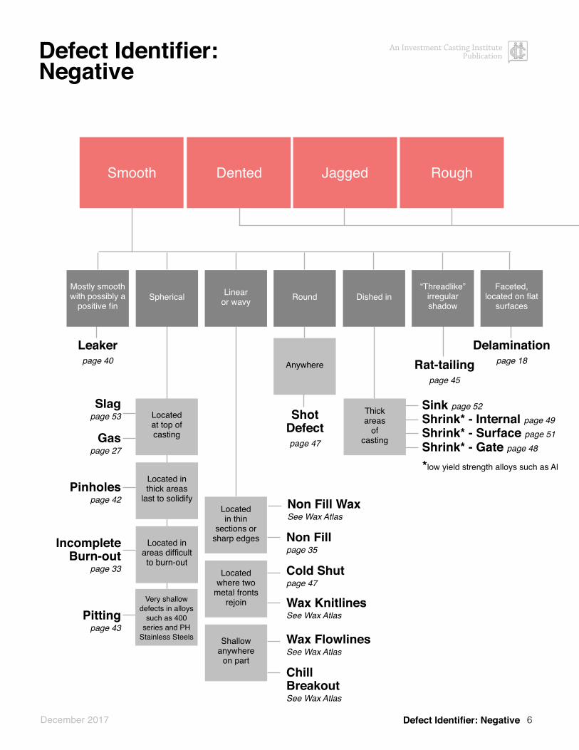
Defect Identifier:Negative
Defect Identifier: Negative
DentedSmooth Jagged Rough
Spherical Linear or wavy
“Threadlike”irregular shadow
Round
Leakerpage 40
Delaminationpage 18Rat-tailing
page 45
Dished inFaceted,
located on flat surfaces
Mostly smooth with possibly a
positive fin
Located at top of casting
Located in thin
sections or sharp edges
Located in thick areas
last to solidify
Located where two
metal fronts rejoin
Located in areas difficult to burn-out
Shallow anywhere
on part
Slag page 53
Gas page 27
Pinholes page 42
IncompleteBurn-out
page 33
Pittingpage 43
Non Fill WaxSee Wax Atlas
Wax FlowlinesSee Wax Atlas
Cold Shutpage 47
Non Fillpage 35
ChillBreakoutSee Wax Atlas
Anywhere
Very shallow defects in alloys
such as 400 series and PH
Stainless Steels
Shot Defectpage 47
Shrink* - Internal page 49Shrink* - Surface page 51Shrink* - Gate page 48
Sink page 52
*low yield strength alloys such as Al
Wax KnitlinesSee Wax Atlas
Thick areas
of casting

7
An Investment Casting Institute Publication
December 2017
Defect Identifier:Negative
Defect Identifier: Negative
DentedSmooth Jagged Rough
Parallel grooves, grind marks near gates,
missing features
Flake or
wafer like
Irregular
Dendratic void in hot spots
such as gates or fillets
Non-MetallicInclusions
(caused by gating undercuts)
page 36
GrindingDamage
page 29
Cut-offDamage
page 17
Jagged surface with one surface having the same shape as letter, number or fillet
Jagged surface typically located
at the bottom of the casting
Spallpage 56
Non-MetallicInclusions
page 36
Areas exposed
to blasting media
Overblastpage 38
Handling Damage
page 30
Jagged, fractured
Cracked or
missingfeatures
WaxCrackpage 15
Wax in Die
See Wax Atlas
Crackpage 15
Hot Tear
page 31
Shrink - Internal page 49
Shrink - Surface page 51
Shrink - Gate page 48
The information pertaining to this defect is available as part of the Wax Atlas. The Wax Atlas can be accessed at www.investmentcasting.org or ordered by contacting (201) 573-9770
8
An Investment Casting Institute Publication
December 2017
Bubbles
Area
Wax
Shell
Shell
Shell
Shell
Shell
Shell
Possible Cause
Bad mold design
Poor dipping technique
Poor draining technique
Incomplete pattern wetting
Insufficient slurry wetting
Incomplete pattern cleaning
High air level in the slurry
Potential Correction
Re-orient the part to prevent air from being trapped during dipping
Immerse the pattern slowly in the slurry, use vibration or, compressed air or vacuum to pop any trapped air bubbles
Back drain slurry into areas that cannot be wet out during dipping
Use a pre-wet or use a lower prime coat viscosity
Insure the correct amount of wetting agent is in the slurry
Insure the silicone is removed from all surfaces of the pat-terns and no air bubbles are preventing proper cleaning
Insure air is not being sucked into the slurry by the mixer. Conduct antifoam test and adjust if necessary
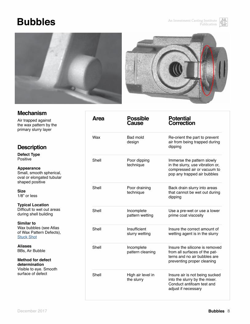
MechanismAir trapped against the wax pattern by the primary slurry layer
DescriptionDefect TypePositive
AppearanceSmall, smooth spherical, oval or elongated tubular shaped positive
Size1/8” or less
Typical LocationDifficult to wet out areasduring shell building
Similar toWax bubbles (see Atlas of Wax Pattern Defects),Stuck Shot
AliasesBBs, Air Bubble
Method for defect determinationVisible to eye. Smooth surface of defect
Bubbles
9
An Investment Casting Institute Publication
December 2017
Buckle
Area
Wax
Wax
Wax
Shell
Shell
Shell
Shell
Possible Cause
Temperature change in wax causes the wax to move and disrupt the primary layer bond. Wax pat-tern temperature not stable
Pattern cleaning inadequate. Poor adhesion of the primary coat to the wax pattern
Pattern flexing during dipping
Large temperature change
Drying too long
Drying too short
Poor prime coat wetting
Potential Correction
Ensure the wax pattern has stabilized in temperature before applying shell layers
Increase etch strength or, time in etch. Reduce the time from etch to primary layer
Add additional pattern supports
Control the dipping area to +/- 3 F
Set a maximum dry time
Insure the primary layer is completely dry before applying backup layers
Confirm the prime slurry is wetting the pattern
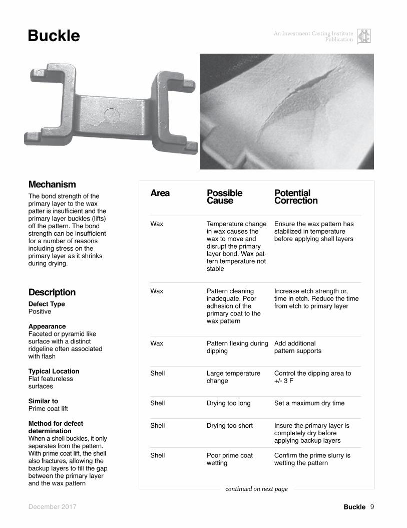
MechanismThe bond strength of the primary layer to the wax patter is insufficient and the primary layer buckles (lifts) off the pattern. The bond strength can be insufficient for a number of reasons including stress on the primary layer as it shrinks during drying.
DescriptionDefect TypePositive
AppearanceFaceted or pyramid like surface with a distinct ridgeline often associated with flash
Typical LocationFlat featureless surfaces
Similar toPrime coat lift
Method for defect determinationWhen a shell buckles, it only separates from the pattern. With prime coat lift, the shell also fractures, allowing the backup layers to fill the gap between the primary layer and the wax pattern
Buckle
continued on next page

10
An Investment Casting Institute Publication
December 2017
Buckle continued
Area
Shell
Shell
Shell
Shell
Shell
Shell
Shell
Shell
Shell
Shell
Shell
Other (Mold design)
Other
Possible Cause
Low adhesion binder
Drying too fast (high pattern shrinkage & drying stress)
Pre-wet is lifting prime
Too much slurry on interior surfaces
Too little slurry on interior surfaces
Insufficient stucco on interior surfaces
Primary slurry in poor condition
Soaking (saturating) the mold promotes lifting. Vibration too high
Pattern flexing during dipping
Soaking (saturating) the mold promotes lifting
Thermal expansion mismatches within the shell
Pattern is too flat and featureless
Pattern flexing during dipping
Potential Correction
Increase polymer level
Slow down (Increase) the drying by reducing airflow or increasing room humidity or reduce airflow
Eliminate pre-wet or reduce dry time between pre-wet and slurry application
Decrease slurry viscosity or increase drain time
Increase slurry viscosity or decrease drain time
Don’t let slurry surface dry or over drain before stucco application
Employ proper slurry controls
Vibration used during dipping can cause the primary coat to separate from the pattern
Add additional pattern supports
Stucco molds immediately after slurry has drained
Change shell composition
Add ribs or dimples to break up flatness and create features
Add additional pattern supports
Buckle
continued from previous page

11
An Investment Casting Institute Publication
December 2017
Bulge
Area
Wax
Shell
Shell
Shell
Shell
Shell
Possible Cause
Patterns too close causing premature bridging
Shell too thin
Mold hot strength too low (mold creeping during casting cooling)
Slurry not wetting out area
Slurry/stucco not getting into area
Stucco not getting into area
Potential Correction
Use spacers during assembly to produce consistent pattern spacing
Add shell layers or add stiff-ening feature
1) Increase refractoriness of the shell2) Ensure optimal SiO2 levels in the backup slurry 3) Ensure uniform mold thickness
1) Use vacuum dipping or re-orient pattern. 2) Use a thinner slurry
Use a “poured core”
1) Rainfall, hand pour or re-orient pattern 2) If bridging in slots or holes, use a finer stucco or make sure hole is open prior to applying subsequent dips until sufficient slurry/stucco has been applied
MechanismPermanent defection of the mold wall either during dewaxing or casting.
DescriptionDefect TypePositive
AppearanceGradual thickening of the cast-ing wall. May have finning in the area of the bulge. May not be detectable by the naked eye but can be caught by gauging.
Typical LocationParallel surfaces, deep holes, or slots. Adjacent patterns on assembly. Large flat feature-less surfaces
Similar toSimilar in appearance to shell buckle but it doesn’t have the definitive shape of a crack in the casting.
AliasesBulging, bulging cracking, bulging overheating, shell bulge
Method for defect determinationShell bulge generally has a more rounded surface
Bulge
continued on next page

12
An Investment Casting Institute Publication
December 2017
Bulge
Bulge
Area
Shell
Shell
Shell
Foundry
Foundry
Foundry
Possible Cause
Slurry is being washed away when subsequent coats are applied
Green strength of the shell is too low to withstand dewaxing
Deformation during dewaxing
Solidification time too long
Ferrostatic pressure too high
Ferrostatic pressure too high
Potential Correction
Ensure sufficient intra-coat dry time and conditions for hard to dry areas of the mold
1) Increase the dry time between each layer2) Apply additional coats3) Increase final dry time4) Redesign assembly to permit a more rapid heat transfer to all parts of mold5) Vent pattern cavities6) Check dewax process for optimal performance and that it is in control
See “Finning”
Decrease metal temperature, decrease mold temperature, speed casting cooling rate
Reduce vacuum level, reduce spinning rate (centrifugal)
Reduce the metal height above the part
continued from previous page

13
An Investment Casting Institute Publication
December 2017
Cold Shut
Area
Foundry
Foundry
Foundry
Foundry
Foundry
Foundry
Possible Cause
Metal not hot enough
Mold not hot enough
For air cast, mold not permeable resulting in backpressure/trap-ping air that slows metal fill time
Poor metal fluidity
Slow metal pour rate
Interrupted pour
Potential Correction
Increase metal superheat
Increase mold temperature/increase or add mold insulation
Reduce shell thickness or gating design to fill pattern cavity from more locations. Add vents. Increase shell permability
Consider modifications to alloy composition
Increase pour rate
Maintain a steady pour rate until mold is full
MechanismIncomplete joining of two metal fronts
DescriptionDefect TypeNegative
AppearanceSmooth, linear, shallow, rounded edged impression extending into feature wall. This defect takes the form of a crack or discontinuity in the surface with rounded edges indicating the freezing or solidifi-cation of two or more streams of metal before they had time to com-pletely fuse together.
Sizevaries
Typical LocationThin sections or areas furthest away from gate where two metal fronts meet.
Similar toWax knitline (see Atlas of Wax Pattern Defects)
AliasesCold Shot, Short Fill
Method for defect determinationPenetrant inspection, visual in-spection, metallographic inspection for evidence of non-bonding along line below cast surface. A wax knit line will have not extend below cast surface ceramic in the junction. Cold Shut

14
An Investment Casting Institute Publication
December 2017
Core Breakage
Area
Wax
Shell
Other (Mold design)
Possible Cause
Mold design creates stress on core upon clamping or wax injection
Poor core slipping method
Too high of wax injection pressure
Potential Correction
Examine need for core print relief or core supports to reduce stress
Examine for too many core locks or “prints”
Reduce injection pressure
MechanismCore breaks either during wax injection, during mold heating, or metal pouring
DescriptionDefect TypeNegative
AppearanceMetal fin across an area that is formed by a ceramic core. In the case of core break and shift, missing metal where a wall should be.
Sizevaries
Typical LocationCan only occur on casting made with ceramic core
Method for defect determinationVisual, X-ray in case of hidden from view
Core Breakage

15
An Investment Casting Institute Publication
December 2017
Crack
Area
Wax
Wax
Foundry
Other (Post-cast operation)
Other (Post-cast machining)
Other (Casting design)
Possible Cause
Major sectional changes in the cast-ing design
Restriction of casting contraction at elevated temperature
Premature movement of mold after casting
Uneven cooling rate -The use of water to cool a hot casting can sets up high internal stress
Removal of cast material can create an imbalance of the internal stress leading to cracking.
Restriction of casting contraction at elevated temperature
Potential Correction
Modify gating to prevent strong gates or runners from preventing the casting from contracting
Modify the design to avoid contraction restriction and strengthen the weak areas by the use of webs
Allow time for the casting to solidify before moving
Avoid rapid cooling methods
Add a stress-relief thermal cycle to as-cast part prior to metal removal operations
Modify the design to avoid contraction restriction and strengthen the weak areas by the use of webs
MechanismTypically, internal stresses from solid-state cooling or rapid cooling can caused cracking.
DescriptionDefect TypeNegative
AppearanceJagged crack with irregular path
Typical LocationGeometry involves seriously restrained contraction or in a local volume of unfed metal. May occur at the intersec-tion of thick and thin section.
Similar toHot Tear
Method for defect determinationVisual inspection and Penetrant inspection typically reveal cracks. Cracks form roughly 90° to stress direction.
Crack
continued on next page

16
An Investment Casting Institute Publication
December 2017
Crack continued
Area
Other (Casting design)
Other (Casting design)
Possible Cause
Major sectional changes in the casting design
Sharp internal angles
Potential Correction
Modify gating to prevent strong gates or runners from preventing the casting from contracting
Ensure adequate fillet radii
Crack
continued from previous page

17
An Investment Casting Institute Publication
December 2017
Cut-off Damage
Area
Other (Gating Design)
Other (Post-Cast operation)
Other (Post-Cast operation)
Possible Cause
Castings too close to the runner bar/variable distance from runner bar
Incorrect part loading in cutoff fixture
Cut-off blade flex during the cut-off
Potential Correction
Increase gate length
Mistake proof the holding fixture
Use different blade, change gate shape
MechanismBlade or plasma torch deflects into casting or continues into casting after cut
DescriptionDefect TypeNegative
AppearanceSlot or beveled face with characteristic grooves running the direction of the cut-off wheel
Typical LocationAnywhere but typically near a gate contact
Method for defect determinationVisual inspection
Cut-off Damage

18
An Investment Casting Institute Publication
December 2017
Delamination
MechanismFailure of bond between 1st and 2nd layer of shell. The first layer is pushed or pulled into the mold cavity usually during dewax. Sometimes the shell cracks and metal fills the gap between the layers producing a scab.
DescriptionDefect TypeNegative
AppearanceFaceted metal indentation sometimes accompanied by a positive metal scab
Typical LocationFlat featureless surfaces
AliasesScabbing, Reverse Buckle
Method for defect determinationVisual, appears as scab with indentation under scab
Delamination
Area
Shell
Shell
Shell
Shell
Shell
Shell
Shell
Possible Cause
Incomplete wetting between 1st and 2nd layer
Etch too strong – too tacky
Drying rate of 2nd layer too high
Poor bond between prime and backup layer
Moisture trapped be-hind the primary coat
Differential expan-sion stresses be-tween the primary and secondary coats
Rapid pressure release during auto-clave dewaxing
Potential Correction
Blow off loose primary coat stucco. Ensure immersion time in 2nd layer slurry is ad-equate to wet-out the primary layer
Reduce etch strength or time
Increase drying room humidity
Ensure adequate keying between the primary and first backup coat. Use a coarser or more angular primary coat stucco blow off loose or excess stucco
Ensure adequate drying of the mold prior to dewaxing
Ensure the thermal expansion of the primary coat is compatible with that of the shell coats
Autoclave blowdown should be gradual and take 2 minutes or more
continued on next page

19
An Investment Casting Institute Publication
December 2017
Delamination
Delamination
Additional examples

20
An Investment Casting Institute Publication
December 2017
Distortion
MechanismDistortion of the casting occurring at wax injection, pattern assembly, or casting cooling.
DescriptionDefect TypeShape
AppearanceThe geometry does not conform to the drawing
Sizevaries
Typical LocationOpposite gate locations
Similar to Sink, Cavitation (See Atlas of Wax Pattern Defects)
Method for defect determinationVisual inspections and customary dimensional inspection tools
Distortion
Area
Other (Casting design)
Other (Mold design)
Other (Mold design)
Wax
Wax
Wax
Wax
Possible Cause
Geometry of the casting and or run-ning system causing uneven contraction
Improper gating system design
Ingates contracting and pulling part of the casting
Improper wax pattern handling ejected from die
Improper wax pattern storage
Ingates contracting and pulling part of the casting
Improper gating system design
Potential Correction
Minimize uneven stresses that develop with solid-state metal contraction occurs
Design the gating and runner system to prevent uneven stresses
Examine the runner system and modify to reduce stresses
Modify release agent spraying technique, frequency. Add ejector pins
Store patterns in a manner to prevent distortion
Examine the runner system and modify to reduce stresses
Design the gating and runner system to prevent distortion
Figure 1 Raised pads are witness to gating locations on the outside of the tube casting.
Figure 2 Depressions on the interior of the tube are created during the casting process.
continued on next page

21
An Investment Casting Institute Publication
December 2017
Distortion
Distortion
Area
Shell
Other
Foundry
Other (Heat treatment)
Possible Cause
High strength mold preventing even contraction
Knockout conducted at too high a temperature
Improper casting handling
Stresses induced during heat treatment
Potential Correction
Reduce the mold strength
Knockout at a lower temperature
Ensure cast molds are handled with care – especially at high temperature
Ensure the castings are correctly supported during heat treatment. Use the slowest quenching method that will achieve the required hardness
continued from previous page
22
An Investment Casting Institute Publication
December 2017
Etch SpottingMechanismDuring pattern cleaning prior to shell building, the etch solution is not completely rinsed off. The etch continues to attack the wax forming rings or drips on the bottom of the pattern
DescriptionDefect TypeNegative and Positive
AppearanceSmooth. Raised droplet or “coffee ring” like appearance where ring may be slightly indented into casting
Special CircumstancesMost common with difficult to rinse etch solutions
Size¼” or less
Typical LocationEnd of part away from the pour cup. Areas where etch rinse water beads up after pattern cleaning or there is insufficient rinse action on the surface of wax. Often in deep corners but can occur on open surfaces.
AliasesFisheyes
Method for defect determinationMonitor the etching operation and inspect wax patterns prior to first dip in pre-wet or primary dip
Etch Spotting
Area
Shell
Shell
Possible Cause
Incomplete rinse after pattern etch
Incorrect etch concentration
Potential Correction
Increase agitation during rinse, keep rinse water clean and/or use multiple rinse tanks. Last rinse water should always be clear to ensure cleanliness. Make sure water temperature is room tempera-ture.
Some etch products require mixing with water prior to use. Verify measurements and test con-centration if possible.

23
An Investment Casting Institute Publication
December 2017
Excess Metal
MechanismThin or weak areas of the shell fail during dewax or casting allowing metal to leak into the void in the shell.
DescriptionDefect TypePositive
AppearanceIrregular shaped mass typically attached to the casting by flash
SizeVaries but typically metal is re-strained by external shell geometry
Typical LocationHoles, slots, or tight corners
AliasesMetal breakthrough, Metal Penetration, Core Collapse
Method for defect determinationVisual Inspection
Excess Metal
Area
Other (Mold design)
Shell
Shell
Shell
Shell
Shell
Shell
Possible Cause
Poor mold design
Poor shell build / slurry / stucco schedule
Incomplete loose stucco removal
Incomplete slurry wetting
Incomplete drying
Incomplete stucco coverage
Stucco too large
Potential Correction
Re-orient the part to improve slurry and stucco coverage
Improve wetting of detail by shell code changes, re-orient-ing the part or vacuum dip-ping, thinner slurries and finer stuccos, use intermediate slurry and or stucco
Blow loose stucco out of detail, slots or blind holes
Change pattern orientation, use vacuum dipping, lower the slurry viscosity or use prewet solutions
Increase the dry time between layers
Pour stucco into the area, change orientation of the pat-tern, use finer or intermediate stucco
Change shell code, use finer stucco
continued on next page

24
An Investment Casting Institute Publication
December 2017
Excess Metal
Excess Metal
Area
Shell
Shell
Shell
Other (Casting design)
Possible Cause
Stucco contains large particles (“rice krispies” or “snerds”)
Dewax cracking
Autoclave depressurization too rapid
The core length to cross-sectional area too great to allow production of a sound core by normal shell techniques
Potential Correction
Sift the large particles out of the stucco
Improve dewax performance
Gradually depressurize the autoclave over 2 minutes or more
Form area with “poured core” or preformed ceramic core
continued from previous page

25
An Investment Casting Institute Publication
December 2017
Finning
MechanismShell crack during shell build-ing, drying or dewaxing, and molten metal fills the crack during casting. Cylindrical shapes are more prone to this defect due to hoop stress
DescriptionDefect TypePositive
AppearanceSharp, linear fin of metal perpendicular to the surface
Typical LocationFlat featureless surfaces, sharp edges or cylindrical parts, across holes
Similar toWax flash (See Atlas of Wax Pattern Defects)
AliasesFlash, Shell Crack, Mold Crack
Method for defect determinationWax flash can only be located on the parting line of the pat-tern
Finning
Area
Wax
Wax
Wax
Shell
Shell
Shell
Shell
Possible Cause
Runner wax melts too slow creating in-creased pressure by part wax on mold as it melts
Pattern wax does not bleed through the mold during dewaxing
Wax flash / parting line not removed
Low mold strength
Incomplete mold drying
Slow autoclave pressurization
Large temperature fluctuations during drying
Potential Correction
Change the formulation of the runner wax to insure it melts as fast or faster than the pat-tern wax, use a low melting point wax to apply “dip seal” to the runner system
Change pattern wax or increase green permeability
Removal all parting line indications
Add an additional shell layer, use a polymer, increase SiO2 of slurry
Increase the mold dry time
The autoclave should rapidly pressurize to 80 psi in 10 seconds or less
Maintain 3F maximum temperature variation
continued on next page
26
An Investment Casting Institute Publication
December 2017
Finning
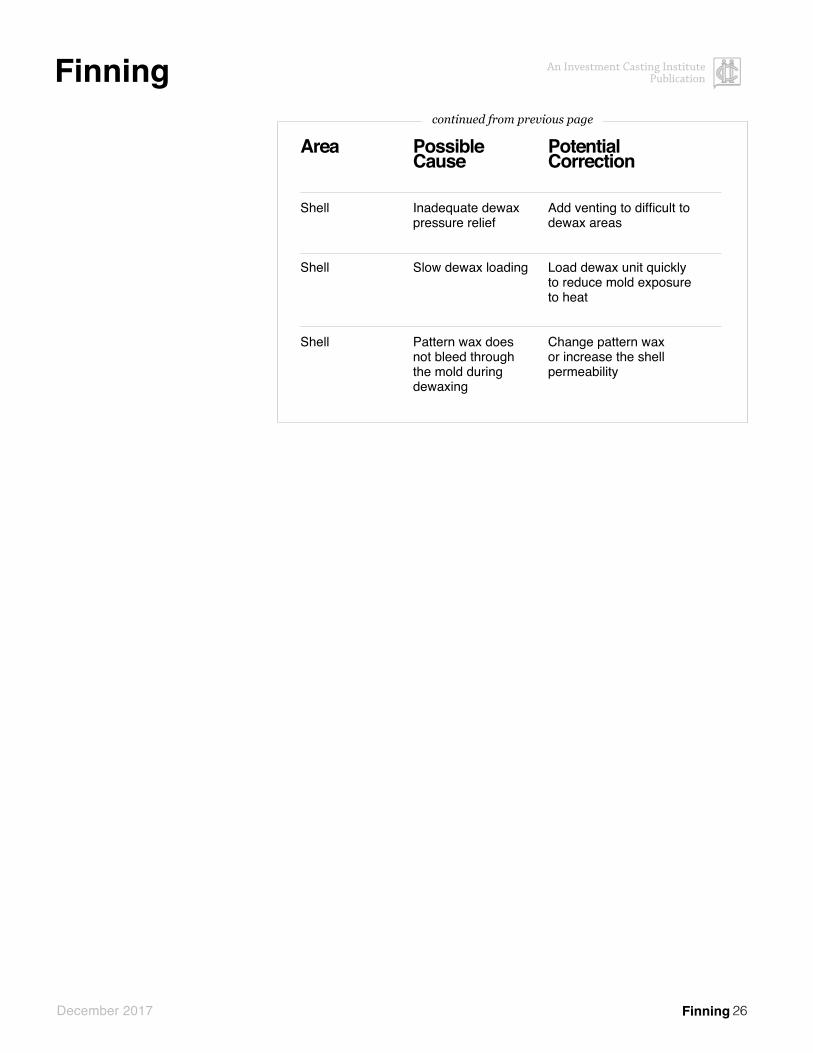
Finning
Area
Shell
Shell
Shell
Possible Cause
Inadequate dewax pressure relief
Slow dewax loading
Pattern wax does not bleed through the mold during dewaxing
Potential Correction
Add venting to difficult to dewax areas
Load dewax unit quickly to reduce mold exposure to heat
Change pattern wax or increase the shell permeability
continued from previous page

27
An Investment Casting Institute Publication
December 2017
Gas
MechanismDuring casting, turbulent flow mixes the air that is exiting the mold with the metal that is entering. These bubbles float to the surface of the metal but are trapped by the solidifying metal. (Like air bubbles trapped under a layer of ice). This also can be caused by incomplete burnout of the wax and filler material in the mold, igniting when the molten metal reaches this material. Gas defects can also be formed when ceramic cores out-gas, or the strengthening materials (such as binders or superglue) applied to cores, burns out (usually associated with low preheat temperatures). Low permeability of molds is another cause of entrapped gas.
DescriptionDefect TypeNegative
AppearanceRound smooth walled cavities which may exhibit a slightly oxidized surface of varying diameter
Size0.5 to 4 mm
continued on next page
Gas
Area
Other (Mold design)
Other (Mold design)
Other (Mold design)
Shell
Foundry
Foundry
Foundry
Possible Cause
Poor gating design
Poor gating design
Low ferrostatic pressure
Low mold permeability
Bad pouring practice
Excessively turbulent metal flow into the mold. Low ferrostatic pressure
Low metal temperature
Potential Correction
Add vent at top of part to allow air to escape
Modify gating system to prevent turbulence during metal filling
Increase the height of the mold, use vacuum assistance, centrifuge
Increase the mold permeability or use vacuum assistance during pouring
Reduce height from ladle to mold, pour down the side of the pour cup
Modify the gating technique to give less turbulent flow; self-venting mold. Increase the height of the mold, use vacuum assistance, centrifuge
Increasing the metal temperature allows more time for gas bubbles to escape before a skin is formed
continued on next page

28
An Investment Casting Institute Publication
December 2017
Gas
Gas
Area
Foundry
Foundry
Foundry
Possible Cause
Excess wax and Filler material after dewaxing mold
Poor deoxidation practices
Moisture contained within the metal feedstock
Potential Correction
Burn molds out fully prior to preheat. Add excess oxygen to preheat/ burnout oven to ensure complete burnout of mold.
Improve practices
Ensure metal is free from moisture rust or lubricants. Ensure ladles are cured and dry before use.
continued from previous pagecontinued from previous page
Typical LocationGenerally located on the upper region of the part as-cast
Similar toPinholes, Blowholes, Slag, Incomplete Burn-out
AliasesEntrapped Air, Porosity
Method for defect determinationUpper region of the part as-cast, only a few holes. Fewer number of cavities than pinholes

29
An Investment Casting Institute Publication
December 2017
Grinding Damage
Grinding Damage
MechanismAbrasive grinding belt or wheel continues grinding into casting af-ter removing the gate
DescriptionDefect TypeNegative
AppearanceMissing features or low wall thickness with linear serrations
Typical LocationNear gates or on same surface as gates
Similar toCutoff Damage
Area
Other
Other
Other
Other
Other
Other
Other
Possible Cause
Grind depth set too deep
Part improperly loaded
Residual ceramic prevents proper fixture loading
Incorrect belt width
Snagging from loose grip in operator’s hand
Excess Snagging from inability to see grind area interface
Incorrect grit size on belt
Potential Correction
Ensure grinding depth set correctly on automatic grinder
Mistake proof part loading on the grind fixture
Improve ceramic removal method
The contact wheel and grind-ing belt should be sized according to the gate width
Hold casting tight in hand when approaching belt or disc
Change view angle
Ensure belt grit size before grinding

30
An Investment Casting Institute Publication
December 2017
Handling Damage
MechanismCastings are damaged at some point after solidification
DescriptionDefect TypeNegative and positive
AppearanceDinged surface. Smooth negative with accompanying positive burr, dented edge, rolled corner, bent or distorted metal
SizeVarious
Typical LocationProtruding features, corners, thin areas
Similar toWax damage (See Atlas of Wax Pattern Defects)
AliasesKnockout Damage
Method for defect determinationVisual or dimensional gauging
Handling Damage
Area
Foundry
Other (Knockout/cutoff/blasting)
Other (Transporting)
Possible Cause
Damage occurring during handling
Damage occurring during mechanical cleaning
Damage occurring during transportation
Potential Correction
Prevent operators from dropping castings onto one another
Reduce tumbling speed or add cushioning material with castings (addition of rubber blocks during tumble blast)
Ensure floors are level, wheels on carts are adequate

31
An Investment Casting Institute Publication
December 2017
Hot Tear
MechanismDuring casting cooling, the strength of the shell or gating system exceeds that of the solidifying metal
DescriptionDefect TypeNegative
AppearanceJagged crack with irregular path, typically with an oxidized fracture face
Typical LocationSlow to cool or solidify areas where the geometry involves seriously restrained contraction or in a local volume of unfed metal. May occur at the intersection of thick and thin section.
Similar toCrack, Wax Crack (See Atlas of Wax Pattern Defects)
AliasesShrinkage Crack
Method for defect determinationA wax crack will typically contain refractory and have a somewhat smooth, non-dendritic fracture face
Hot Tear
Area
Wax
Wax
Shell
Shell
Shell
Foundry
Foundry
Possible Cause
Restriction of casting contraction at elevated temperature
Major sectional changes in the casting design
Sharp internal angles
Gating incorrect
Shell too strong
Premature movement of mold after casting
Uneven cooling rate
Potential Correction
Modify the design to avoid contraction restriction and strengthen the weak areas by the use of webs.
Modify gating to prevent strong gates or runners from preventing the casting from contracting
Ensure adequate fillet radii
Reduce the mold strength. Modify gating to prevent strong gates or runners from preventing the casting from contracting Use a slower cooling rate
Reduce shell layers. Allow time for the casting to solidify before moving
Allow time for the casting to solidify before moving
Sink mold after casting or wrap in insulation
continued on next page

32
An Investment Casting Institute Publication
December 2017
Hot Tear
Hot Tear
Area
Foundry
Foundry
Foundry
Other (Mold design)
Other (Casting design)
Other (Casting design)
Other (Mold Design)
Other (Casting design)
Possible Cause
Gating incorrect
Metal chemistry
Metal chemistry
Gating incorrect
Sharp internal angles
Casting design
Restriction of casting contraction at elevated temperature
Major sectional changes in the casting design
Potential Correction
Reduce the mold strength. Modify gating to prevent strong gates or runners from preventing the casting from contracting Use a slower cooling rate
Use certified virgin ingots
Modify the metal chemistry
Reduce the mold strength. Modify gating to prevent strong gates or runners from preventing the casting from contracting Use a slower cooling rate
Ensure adequate fillet radii
Modify the casting design where possible to reduce major sectional changes
Modify the design to avoid contraction restriction and strengthen the weak areas by the use of webs.
Modify gating to prevent strong gates or runners from preventing the casting from contracting
continued from previous page
33
An Investment Casting Institute Publication
December 2017
Incomplete Burn-out
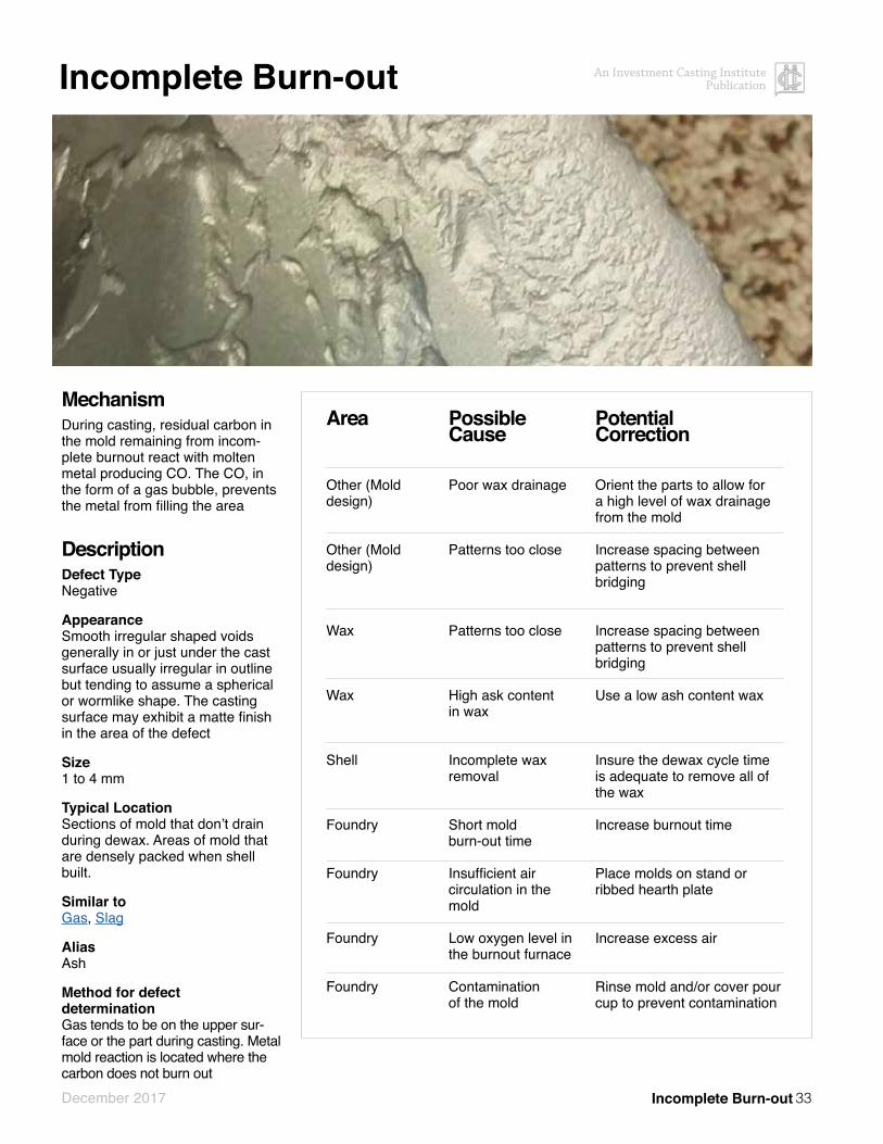
MechanismDuring casting, residual carbon in the mold remaining from incom-plete burnout react with molten metal producing CO. The CO, in the form of a gas bubble, prevents the metal from filling the area
DescriptionDefect TypeNegative
AppearanceSmooth irregular shaped voids generally in or just under the cast surface usually irregular in outline but tending to assume a spherical or wormlike shape. The casting surface may exhibit a matte finish in the area of the defect
Size1 to 4 mm
Typical LocationSections of mold that don’t drain during dewax. Areas of mold that are densely packed when shell built.
Similar toGas, Slag
AliasAsh
Method for defect determinationGas tends to be on the upper sur-face or the part during casting. Metal mold reaction is located where the carbon does not burn out
Incomplete Burn-out
Area
Other (Mold design)
Other (Mold design)
Wax
Wax
Shell
Foundry
Foundry
Foundry
Foundry
Possible Cause
Poor wax drainage
Patterns too close
Patterns too close
High ask content in wax
Incomplete wax removal
Short mold burn-out time
Insufficient air circulation in the mold
Low oxygen level in the burnout furnace
Contamination of the mold
Potential Correction
Orient the parts to allow for a high level of wax drainage from the mold
Increase spacing between patterns to prevent shell bridging
Increase spacing between patterns to prevent shell bridging
Use a low ash content wax
Insure the dewax cycle time is adequate to remove all of the wax
Increase burnout time
Place molds on stand or ribbed hearth plate
Increase excess air
Rinse mold and/or cover pour cup to prevent contamination

34
An Investment Casting Institute Publication
December 2017
Leaker
MechanismMetal leaks out of the mold during or immediately after casting
DescriptionDefect TypeNegative
AppearanceSmooth in most instances, but also be rough. It could be irregular. Many features or runners missing because of lack of metal. May have a positive fin where the leak-er occurred.
Typical LocationTop of casting as oriented during casting
AliasesRunout, Short Pour
Method for defect determinationVisual inspection
Leaker
Area
Wax
Shell
Shell
Shell
Shell
Shell
Foundry
Foundry
Possible Cause
Handling damage
Broken shell – handling damage.
Low mold strength
Dewax cracking
Poor patch coverage– incomplete drying
Handling damage
Rough handling of hot mold
Handling damage
Potential Correction
Examine process and add preventive measures
Improve dewaxing perfor-mance or dip molds after dewaxing, mold handling to prevent damage to the mold
Verify slurry in spec and con-trol or add shell layers
Fill mold with colored dye/ water mix to identify crack locations. Add wax vents. Improve dewaxing performance
Modify patching procedure to insure complete drying prior to placing in burnout oven
Examine process and add preventive measures
Examine process and add preventive measures
Examine process and add preventive measures

35
An Investment Casting Institute Publication
December 2017
Non Fill
MechanismDuring casting, the metal freezes before mold cavity is completely filled out
DescriptionDefect TypeNegative
AppearanceIncomplete casting with rounded edges where casting is not com-pletely formed
Typical LocationThin sections and sharp edges away from the gate
Similar toCold Shut, Wax non fill (See Atlas of Wax Pattern Defects)
AliasesMisrun
Method for defect determinationVisual Inspection
Non Fill
Area
Shell
Foundry
Foundry
Foundry
Foundry
Foundry
Possible Cause
Low mold permeability
Low metal pouring temperature
Low mold temperature
Interrupted pour.
Lack of metal fluidity
Poor gating system
Potential Correction
Increase shell permability. Consider reducing shell thickness. Vent thin sections
Increase metal temperature, improve ladle preheating, speed time from tap to pour
Speed time from oven to cast or insulate mold to pre-vent heat loss
Pour without interruption
Increase fluidity by reducing metal oxides or adjustment of the metal chemistry
Modify gating design to cre-ate more entry points for alloy

36
An Investment Casting Institute Publication
December 2017
Non-Metallic Inclusion
MechanismForeign material in the mold cavity which can originate either from the mold or from outside the mold. The shape of the defect aids in determination of the source
DescriptionDefect TypeNegative
AppearanceGenerally a smooth sided irregular negative shape of indefinite size. Inclusions caused by ceramic material are usually more angular and may contain bits of embedded ceramic.
SizeVariable
Typical LocationMost obvious on external surface of casting where the “inclusion” prevented the alloy from filling the mold cavity to the shell surface.
AliasesDirt, Ash
Method for defect determinationVisual Inspection
Non-Metallic Inclusion
Area
Wax
Wax
Wax
Wax
Wax
Shell
Possible Cause
Junction between wax gate and sprue not completely sealed (undercuts). Ceramic fills the un-dercut during shelling and breaks off during dewax or pouring.
Filter breakage
Ash in wax – as in wax typically floats in the molten alloy and is present on the top-side of castings
Incomplete soluble removal
Filler settles out in areas that do not drain during dewaxing
Cracks in mold and ceramic bits get into mold cavity
Potential Correction
Improve gating technique to eliminate undercuts. Make sure wax joints (parts to sprue) are sooth and complete.
Test ash content of wax
Confirm soluble leaching process and inspection is adequate
Reconfigure gating design to improve wax removal. Add wax bleeder
See Finning
continued on next page

37
An Investment Casting Institute Publication
December 2017
Area
Shell
Shell
Shell
Shell
Shell
Shell
Cause
Poor mold patching technique – patch enters mold
Poor adhesion of shell layers to one another
Ceramic debris entering mold after dewaxing (poor housekeeping)
Ceramic breaking loose inside the mold during dewaxing
Slurry floods pour cup during shell building
Ceramic material from jagged lip/edg-es on in house shell built pouring cups is broken off during handling, burnout or casting
Potential Correction
Improve patch technique
See Spall
Cover the pour cup after dewaxing (allow moisture from the mold to escape). Store the mold cup down. Wipe rim of pour cup before turning up-right
Vacuum or wash out mold after dewaxing
Cover pour cup, immediately rinse slurry out. Remove all dried ceramic prior to dewax-ing. Coat the inside of the pour cup with wax prior to shelling to aid in slurry remov-al from cup during dewax.
Use a preformed ceramic pour cup or assure in house shelled cup is uniform and robust on top edge
continued from previous page
Non-Metallic Inclusion
Non-Metallic Inclusion

38
An Investment Casting Institute Publication
December 2017
Overblast
Overblast
MechanismThe blasting media used in me-chanical cleaning equipment is typically harder than the casting. The surface of the casting can be deformed or eroded by extended blasting time or excessive blasting energy.
DescriptionDefect TypeNegative
AppearanceSmall negatives possibly with accompanying burrs. Textured surface. May have rolled edges. Eroded features
Typical LocationSurfaces exposed to shot or sand blast media
AliasesBlasting damage
Area
Other
Other
Other
Other
Other
Possible Cause
The casting are too hot during blasting
Castings are stopped in front of the blasting nozzle or wheel
Blast time is too long
Blast media is too large
Blast media is too hard
Potential Correction
Allow parts to cool prior to blasting
Insure the parts are constantly moving during the blasting cycle. Check the mill or spinners to confirm movement during the blast cycle
Reduce blast time
Reduce blast media size
Use softer blast media

39
An Investment Casting Institute Publication
December 2017
OxideMechanismDuring casting a refractory oxide skin is formed in the melt through the exposure of reactive elements to oxygen. Certain elements are more reactive than others and will preferentially oxidize. The metallic oxide that is formed can be aggravated with turbulent filling.
DescriptionDefect TypeNegative
AppearanceMetallic oxides are thin black sub-surface streamers forming an irregular pattern or agglom-eration on the surface of the casting.
Special CircumstancesMore commonly encountered with alloys containing highly reactive elements (Ti, Al, Zr, Cr, etc.)
Size Varies
Typical LocationSurface and subsurface
Similar toRat-tailing, Cold shut, Slag AliasesOxide Folds, Dross, Slag, Oxide Film
Method for defect determinationMetallic oxide indications tend to be thin, irregular, randomly placed or located, strings of materials containing oxygen and reactive elements. Metallic oxide indications can be determined by visual or EDS inspection.
Oxide
Area
Foundry
Foundry
Foundry
Foundry
Possible Cause
Impure melting stock
Oxidation of reactive elements
Improper deoxidation practice
Turbulence
Potential Correction
Use oxide-free melting stock or filters
Prevent oxidation of the melt through the use of vacuum or protective atmosphere
Allow time for deoxidation adds to be effective, agitate melt and de-slag for improved deoxidation
Reduced filling speed

40
An Investment Casting Institute Publication
December 2017
Penetration
MechanismMetal penetrates into the primary layer during casting. Pinholes or air pockets in the primary layer fill with metal during casting
OR
Stucco penetrates the primary surface and traps an air pocket against the wax
DescriptionDefect TypePositive
AppearanceSmall discrete positives which appear like grains of sand. When severe, the positives are closely clustered and the surface feels like sandpaper
Typical LocationNear gates, heavy sections or slow to cool sections of the casting
AliasesBurn-in, burn on, pimpling, stucco penetration, rough surface
Method for defect determinationVisual inspection
Penetration
Area
Shell
Shell
Shell
Shell
Shell
Shell
Possible Cause
Stucco particles too large
Incomplete slurry mixing
Foaming in slurry
Primary slurry insta-bility (micro-gelling) refractory solids)
Prime slurry layer too thin
Reaction with primary coat contaminants
Potential Correction
Change shell code, use finer stucco on the first few shell layers
Insure the slurry is completely mixed before using in production
Insure air is not being sucked into the slurry by the mixer. Conduct antifoam test and adjust if necessary
Conduct gel test on binder solution. Replace slurry if bad
Increase slurry viscosity or reduce slurry drain time. Modify drain orientation. Double dip the mold in the slurry. Increase the pre-wet drain time or orientation
Ensure rusting or corrosion of the mixing equipment is not occurring. Remove iron contamination with magnets
continued on next page
41
An Investment Casting Institute Publication
December 2017
Penetration
Penetration
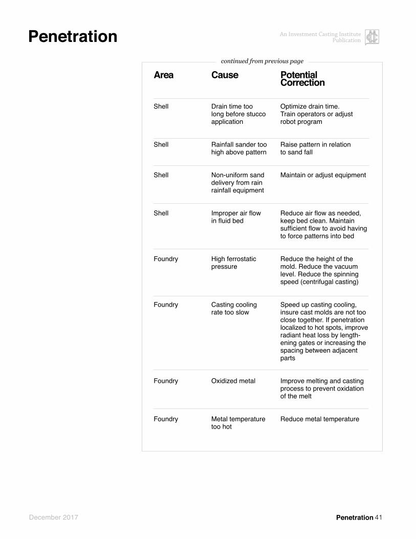
Area
Shell
Shell
Shell
Shell
Foundry
Foundry
Foundry
Foundry
Cause
Drain time too long before stucco application
Rainfall sander too high above pattern
Non-uniform sand delivery from rain rainfall equipment
Improper air flow in fluid bed
High ferrostatic pressure
Casting cooling rate too slow
Oxidized metal
Metal temperature too hot
Potential Correction
Optimize drain time. Train operators or adjust robot program
Raise pattern in relation to sand fall
Maintain or adjust equipment
Reduce air flow as needed, keep bed clean. Maintain sufficient flow to avoid having to force patterns into bed
Reduce the height of the mold. Reduce the vacuum level. Reduce the spinning speed (centrifugal casting)
Speed up casting cooling, insure cast molds are not too close together. If penetration localized to hot spots, improve radiant heat loss by length-ening gates or increasing the spacing between adjacent parts
Improve melting and casting process to prevent oxidation of the melt
Reduce metal temperature
continued from previous page
42
An Investment Casting Institute Publication
December 2017
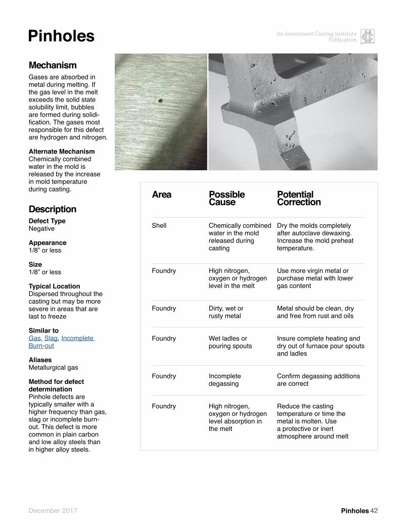
PinholesMechanismGases are absorbed in metal during melting. If the gas level in the melt exceeds the solid state solubility limit, bubbles are formed during solidi-fication. The gases most responsible for this defect are hydrogen and nitrogen.
Alternate MechanismChemically combined water in the mold is released by the increase in mold temperature during casting.
DescriptionDefect TypeNegative
Appearance1/8” or less
Size1/8” or less
Typical LocationDispersed throughout the casting but may be more severe in areas that are last to freeze
Similar toGas, Slag, Incomplete Burn-out
AliasesMetallurgical gas
Method for defect determinationPinhole defects are typically smaller with a higher frequency than gas, slag or incomplete burn-out. This defect is more common in plain carbon and low alloy steels than in higher alloy steels.
Pinholes
Area
Shell
Foundry
Foundry
Foundry
Foundry
Foundry
Possible Cause
Chemically combined water in the mold released during casting
High nitrogen,oxygen or hydrogen level in the melt
Dirty, wet or rusty metal
Wet ladles or pouring spouts
Incomplete degassing
High nitrogen, oxygen or hydrogen level absorption in the melt
Potential Correction
Dry the molds completely after autoclave dewaxing. Increase the mold preheat temperature.
Use more virgin metal or purchase metal with lower gas content
Metal should be clean, dry and free from rust and oils
Insure complete heating and dry out of furnace pour spouts and ladles
Confirm degassing additions are correct
Reduce the casting temperature or time the metal is molten. Use a protective or inert atmosphere around melt

43
An Investment Casting Institute Publication
December 2017
Pitting
MechanismOxygen reacts with chrome in the metal immediately after casting
DescriptionDefect TypeNegative
AppearanceA multiplicity of dark colored shallow depressions covering a large portion of the casting
Special CircumstancesCan only occur in high chrome alloys such as 400 series and PH stainless steels
Typical LocationThick, slow to cool sections
Similar toGas, Incomplete Burn-out, Slag
AliasesChrome Oxide Pitting, Fusion Spot, Measles
Method for defect determinationAlloy, number of defect sites, depth of defect
Pitting
Area
Foundry
Foundry
Foundry
Possible Cause
Surface oxidation of high chrome-iron alloys
Lack of carbona-ceous material in mold
Casting cooling rate too slow
Potential Correction
Ensure reducing or inert conditions immediately after casting. Cover the molds after casting. Use carbonaceous materials in or around the mold. Cool in vacuum or protective or inert atmosphere
Reduce mold burnout time or add additional carbon layers during shell building
Increase casting cooling rate

44
An Investment Casting Institute Publication
December 2017
Prime Coat Lift
MechanismDuring shell building, the primary coat cracks and lifts off the pattern. Subsequent slurry layers pene-trate and fill the gap between the pattern and the primary coat. This defect is a close cousin to buckle
DescriptionDefect TypePositive
AppearanceIsland of surplus metal often as-sociated with flash at the casting edge. The edge of the defect has the appearance of a coastline
Typical LocationSharp corners adjacent to flat or featureless surfaces
Similar toBuckle
AliasesPrimary coat buckle, investment penetration
Method for defect determinationWith prime coat lift, the shell also fractures, allowing the backup layers to fill the gap between the primary layer and the wax pattern. When a shell buckles, it only separates from the pattern.
Prime Coat Lift
Area
Wax
Shell
Shell
Shell
Shell
Shell
Shell
Shell
Shell
Shell
Possible Cause
Wax pattern temperature not stable
Poor adhesion of the prime coat to the wax pattern
Large temperature drop when applying 2nd layer
Large temperature variation during prime coat drying
Drying too long
Drying too fast (large pattern shrinkage)
Primary coat binder is gelled
Uneven primary coating thickness giving rise to variable rates of drying
Slurry dry out on sharp edges
Poor adhesion and elasticity properties of the primary slurry
Potential Correction
Ensure the wax pattern has stabilized in temperature before applying shell layers
Increase the etch strength or etch time. Reduce the time from etch to 1st layer application
Increase the room humidity
Maintain +/- 3 F in the dipping and drying area
Shorten the dry time
Increase the room humidity or reduce airflow
Test the primary coat binder to determine if it is gelled
Modify the draining technique to produce a more uniform slurry coverage
Shorten the draining time, increase the humidity in the shell dipping area
Green strength additives in the primary slurry becoming unstable or ineffective

45
An Investment Casting Institute Publication
December 2017
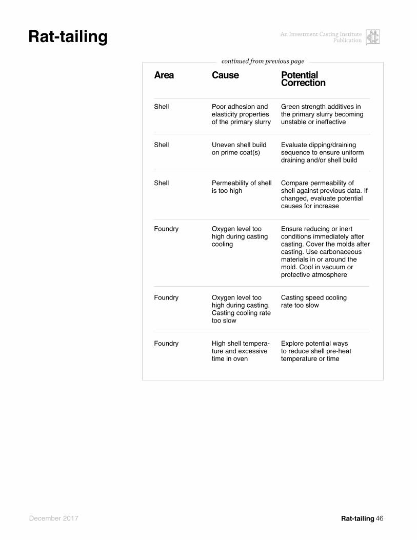
Rat-tailing
MechanismThis defect is a marriage of pitting and finning defects. Rat-tailing is the selective oxidation of the metal surface through cracks or micro-cracks in the shell. Most of the cracks are large enough to be filled with metal during pouring and will produce positive metal fins. Very fine micro-cracks are too small to allow metal to enter, but will allow air (oxygen) to reach the hot casting surface.
DescriptionDefect TypeNegative with the possibility of positive finning
AppearanceShallow rounded threadlike fis-sures typically in a radial pattern
AliasesMud cracks, drying cracks, oxida-tion crazing, rivering
Method for defect determinationThin, negative defect typically found in high chrome alloys
Rattailing
Area
Other (Set-up )
Shell
Shell
Shell
Shell
Shell
Shell
Possible Cause
Lack of stress raisers on the cast surfaces or in the primary coat refractories
Large temperature variation during prime coat drying
Drying too fast (large pattern shrinkage)
Mismatch in ex-pansion coefficient between prime and backup coats
Drying too long
Low prime coat strength
Low prime coat strength
Potential Correction
Break-up large flat surfaces on the casting with “hatching” or small ribs which can subsequently be ground off
Maintain +/- 3F in the drying area
Casting cooling rate too slow. Increase dipping and drying room humidity, reduce air flow
Use slurry and stucco refractories with similar thermal expansion rates
Reduce dry time. cooling rate too slow
Check binder healthy/stability through pH, conductivity and/or gel test
Increase refractory solids
continued on next page
46
An Investment Casting Institute Publication
December 2017
Rat-tailing
Rat-tailing
Area
Shell
Shell
Shell
Foundry
Foundry
Foundry
Cause
Poor adhesion and elasticity properties of the primary slurry
Uneven shell build on prime coat(s)
Permeability of shell is too high
Oxygen level too high during casting cooling
Oxygen level too high during casting. Casting cooling rate too slow
High shell tempera-ture and excessive time in oven
Potential Correction
Green strength additives in the primary slurry becoming unstable or ineffective
Evaluate dipping/draining sequence to ensure uniform draining and/or shell build
Compare permeability of shell against previous data. If changed, evaluate potential causes for increase
Ensure reducing or inert conditions immediately after casting. Cover the molds after casting. Use carbonaceous materials in or around the mold. Cool in vacuum or protective atmosphere
Casting speed cooling rate too slow
Explore potential ways to reduce shell pre-heat temperature or time
continued from previous page

47
An Investment Casting Institute Publication
December 2017
Shot Defect
MechanismDuring casting, droplets of met-al detach or are separated from the pouring stream by excessive turbulence, mold design, or metal pouring height. The metal droplet becomes either cooler in tempera-ture or coated with a tenacious oxide film and retains this identity as part of the cast metal.
DescriptionDefect TypeNegative
Appearance These are closely related to oxide fold defects but are typically circular in form rather than linear
SizeCan be small up to an inch or more in diameter
Typical LocationGenerally located on the surface of the casting
Similar toWax flow lines (See Atlas of Wax Pattern Defects)
AliasesOxidized droplet
Method for defect determinationVisual or Fluorescent Penetrant Inspection
Shot Defect
Area
Wax
Other (Mold design)
Foundry
Foundry
Foundry
Foundry
Possible Cause
Cold wax at nozzle tip
Bad mold design
Bad pouring practice
Bad pouring practice
Pouring practice
Pouring practice
Potential Correction
Wax cold shot can occur in the wax pattern and be duplicated through the shell-ing process, thereby resulting in a similar-looking metal defect. (Ensure nozzle tip temperature is adequate to keep wax from solidifying).
Mold design should promote non-turbulent metal flow
Avoid metal splashing during pouring
Reducing the distance between the crucible and the mold to be poured to minimum, thereby reducing the chance for splashing
Employ use of a reticulated foam filter to achieve a laminar flow
Formation of a well in the mold to allow the metal to collect and then flow into the mold parts
48
An Investment Casting Institute Publication
December 2017
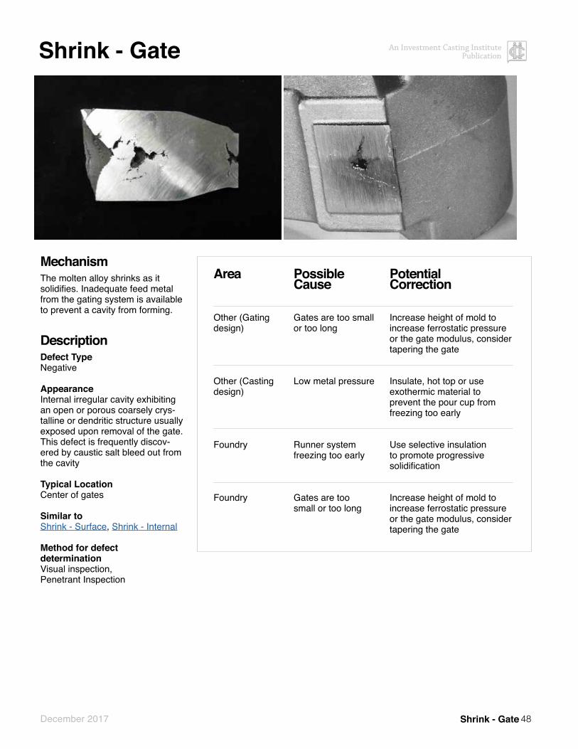
Shrink - Gate
MechanismThe molten alloy shrinks as it solidifies. Inadequate feed metal from the gating system is available to prevent a cavity from forming.
DescriptionDefect TypeNegative
Appearance Internal irregular cavity exhibiting an open or porous coarsely crys-talline or dendritic structure usually exposed upon removal of the gate. This defect is frequently discov-ered by caustic salt bleed out from the cavity
Typical LocationCenter of gates
Similar toShrink - Surface, Shrink - Internal
Method for defect determinationVisual inspection, Penetrant Inspection
Shrink - Gate
Area
Other (Gating design)
Other (Casting design)
Foundry
Foundry
Possible Cause
Gates are too small or too long
Low metal pressure
Runner system freezing too early
Gates are too small or too long
Potential Correction
Increase height of mold to increase ferrostatic pressure or the gate modulus, consider tapering the gate
Insulate, hot top or use exothermic material to prevent the pour cup from freezing too early
Use selective insulation to promote progressive solidification
Increase height of mold to increase ferrostatic pressure or the gate modulus, consider tapering the gate

49
An Investment Casting Institute Publication
December 2017
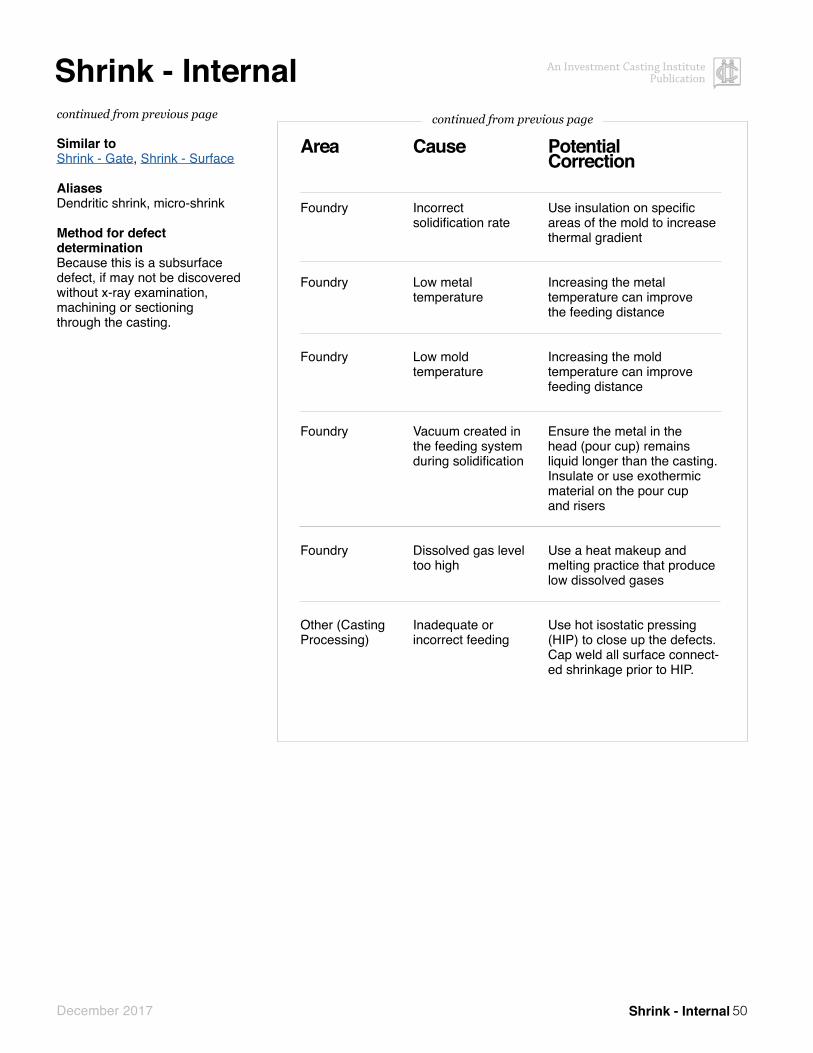
Shrink - Internal
MechanismMolten alloys shrink as they solidi-fy. As solidification progresses and the solid to liquid fraction increases, it becomes more diffi-cult for liquid feed metal to reach the solidification front. Shrinkage occurs between dendritic arms. In larger defects, inadequate feed metal is provided to isolated hot spots in the casting.
DescriptionDefect TypeNegative
AppearanceInternal irregular cavities ranging from small dispersed or linear type cavities up to large cavities
Special CircumstancesThe occurrence and severity of this defect may be alloy dependent. Alloys with longer (larger) freezing ranges are more prone to this defect.
SizeShrinkage cavities can range in size from very small (requiring magnification) to very large
Typical LocationCasting centerline between gates or in isolated heavy sections. Areas with sharp internal corners
continued on next page
Shrink - Internal
Area
Other (Mold design)
Other (Mold design)
Other (Mold design)
Other (Mold design)
Other (Mold design)
Other (Mold design)
Foundry
Possible Cause
Inadequate or incorrect feeding
Incorrect solidification rate
Vacuum in blind riser
Blind riser too small
Low ferrostatic head pressure
Incorrect solidification rate
Incorrect casting conditions
Potential Correction
Ensure adequate feeding of the area concerned to promote progressive solidification
Modify the casting design to promote progressive solidification
Ensure the v-notch in the riser prevents a vacuum from forming
Ensure the riser has adequate metal volume
Increase the height of the mold. Use centrifugal force to increase head pressure
Examine the molding technique. Modify the casting design to promote progressive solidification.
Establish the correct casting conditions
continued on next page
50
An Investment Casting Institute Publication
December 2017
Shrink - Internal
Shrink - Internal
Area
Foundry
Foundry
Foundry
Foundry
Foundry
Other (Casting Processing)
Cause
Incorrect solidification rate
Low metal temperature
Low mold temperature
Vacuum created in the feeding system during solidification
Dissolved gas level too high
Inadequate or incorrect feeding
Potential Correction
Use insulation on specific areas of the mold to increase thermal gradient
Increasing the metal temperature can improve the feeding distance
Increasing the mold temperature can improve feeding distance
Ensure the metal in the head (pour cup) remains liquid longer than the casting. Insulate or use exothermic material on the pour cup and risers
Use a heat makeup and melting practice that produce low dissolved gases
Use hot isostatic pressing (HIP) to close up the defects. Cap weld all surface connect-ed shrinkage prior to HIP.
continued from previous pagecontinued from previous page
Similar toShrink - Gate, Shrink - Surface
AliasesDendritic shrink, micro-shrink
Method for defect determinationBecause this is a subsurface defect, if may not be discovered without x-ray examination, machining or sectioning through the casting.
51
An Investment Casting Institute Publication
December 2017
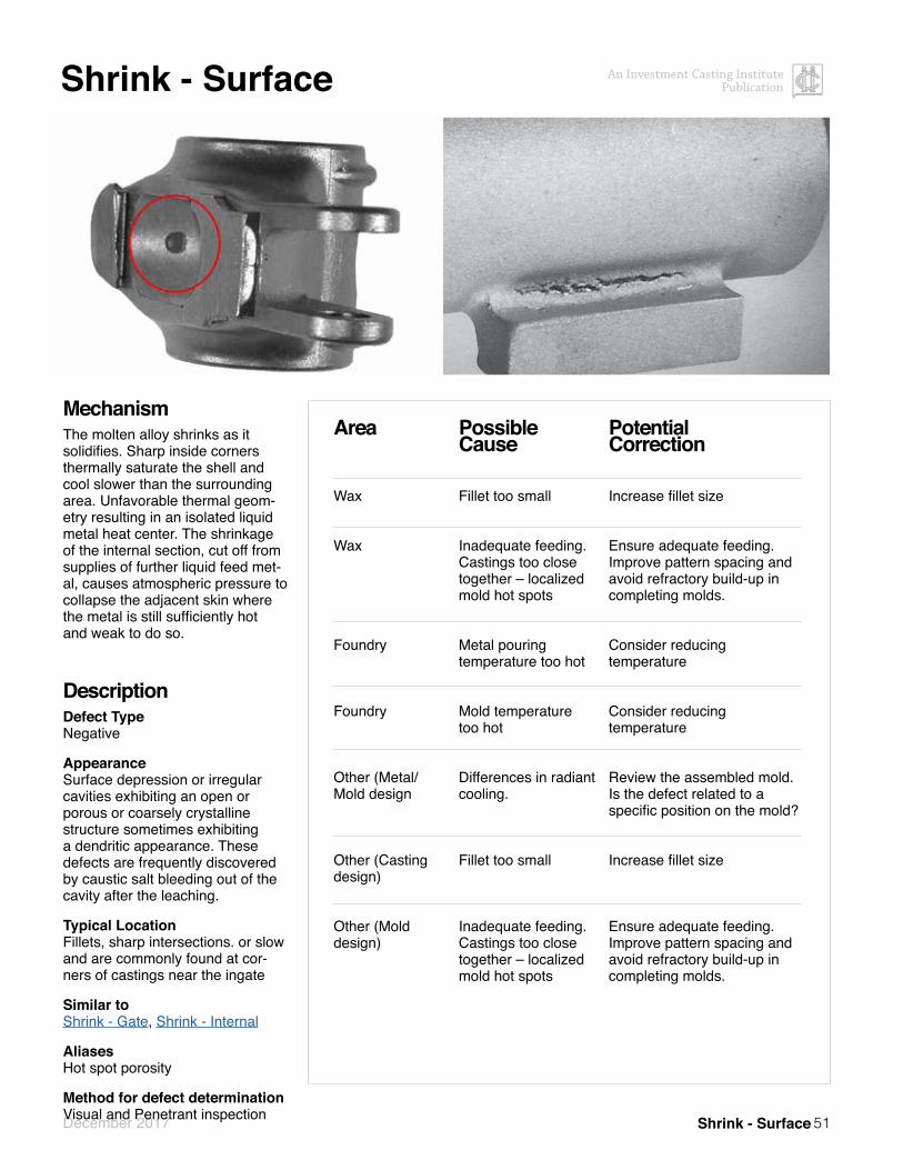
Shrink - Surface
MechanismThe molten alloy shrinks as it solidifies. Sharp inside corners thermally saturate the shell and cool slower than the surrounding area. Unfavorable thermal geom-etry resulting in an isolated liquid metal heat center. The shrinkage of the internal section, cut off from supplies of further liquid feed met-al, causes atmospheric pressure to collapse the adjacent skin where the metal is still sufficiently hot and weak to do so.
DescriptionDefect TypeNegative
AppearanceSurface depression or irregular cavities exhibiting an open or porous or coarsely crystalline structure sometimes exhibiting a dendritic appearance. These defects are frequently discovered by caustic salt bleeding out of the cavity after the leaching.
Typical LocationFillets, sharp intersections. or slow and are commonly found at cor-ners of castings near the ingate
Similar toShrink - Gate, Shrink - Internal
AliasesHot spot porosity
Method for defect determinationVisual and Penetrant inspection Shrink - Surface
Area
Wax
Wax
Foundry
Foundry
Other (Metal/Mold design
Other (Casting design)
Other (Mold design)
Possible Cause
Fillet too small
Inadequate feeding. Castings too close together – localized mold hot spots
Metal pouring temperature too hot
Mold temperature too hot
Differences in radiant cooling.
Fillet too small
Inadequate feeding. Castings too close together – localized mold hot spots
Potential Correction
Increase fillet size
Ensure adequate feeding. Improve pattern spacing and avoid refractory build-up in completing molds.
Consider reducing temperature
Consider reducing temperature
Review the assembled mold. Is the defect related to a specific position on the mold?
Increase fillet size
Ensure adequate feeding. Improve pattern spacing and avoid refractory build-up in completing molds.

52
An Investment Casting Institute Publication
December 2017
Sink
MechanismHeavy section of wax pattern shrinks as it cools. The vacuum created during cooling causes the surface to cavitate or dish inward.
DescriptionDefect TypeNegative
AppearanceSmooth, dished surface depression
Sizevaries
Typical LocationHeavy sections or thick flat surfaces
Similar toWax Shrink (See Atlas of Wax Pattern Defects)
AliasesCavitation
Method for defect determinationVisual inspection, overlay of straight edge or customary dimensional inspection tools
Sink
Area
Other (Wax Tool Design)
Wax
Wax
Wax
Possible Cause
Feed runner freezing prematurely
Incorrect wax injection parameters
Missing wax chill
Hot wax chill
Potential Correction
Increase size or add runner to affected section
Reduce wax temperature, increase injection time, increase injection pressure
Create wax chill to reduce the volume of injected wax in the area of sink/cavitation
Allow time for the wax chill to cool to room temperature before inserting in the wax injection die

53
An Investment Casting Institute Publication
December 2017
Slag
MechanismDuring melting or casting, slag is produced as a function of time, temperature and availability of ox-ygen. This slag is mixed with the metal during pouring and, being less dense than the metal, floats to the top surface of the casting.
DescriptionDefect TypeNegative
Appearance A series of smooth-walled symmet-rical surface cavities with or with-out traces of dark glassy included material
Typical LocationTop surface of the casting as ori-ented at casting
Similar toGas, Pinholes, Incomplete Burn-out
Method for defect determinationIt is difficult to visually distinguish between slag and gas defects. The defect shapes are similar as is the location. Inspection of the defect under magnification may reveal residual slag.
Slag
Area
Shell
Foundry
Foundry
Foundry
Foundry
Foundry
Foundry
Possible Cause
Metal / mold reaction
Crucible / metal reaction
Oxidation of furnace lining or ladle
Poor or improper deslagging practice
Excessive superheat temperature and or holding times
Oxidation of metal during melting
Silicates formed during deoxidation
Potential Correction
Cast at the lowest possible mold and metal temperature. Increase the refractoriness of the primary coat
Employ correct crucible and melting practice
Change to more refractory material
Ensure adequate slag removal at lowest possible temperature. Allow time for slag in melt to float out. Remove slag. Use slag coagulants if necessary to improve removal.
Minimize the time the metal is at temperature
Consider protecting the melt using inert gas
Modify the deoxidation practice
continued on next page

54
An Investment Casting Institute Publication
December 2017
Slag
Slag
Area
Foundry
Foundry
Foundry
Cause
Slag from the ladle entering the mold
Slag from ladle entering the mold
Turbulent pouring conditions - metal poured from great height above molds
Potential Correction
Use ceramic or cloth filter
Consider using a bottom pour (teapot) ladle
Minimize the distance from the furnace / ladle to the mold
continued from previous page

55
An Investment Casting Institute Publication
December 2017
Slurry Leakage
MechanismLiquid ceramic slurry enters the mold and dries creating a positive in the mold that is represented as a negative in the casting
DescriptionDefect TypeNegative
AppearanceShallow, irregular depression in casting surface
Sizevaries
Typical LocationNear wax vent or in mold crack
Method for defect determinationVisual inspection
Slurry Leakage
Area
Shell
Other (Mold Preparation)
Possible Cause
Damage to coating creates separation from wax passage for slurry entry
Inadvertent spill
Potential Correction
Awareness/Handling
Awareness/Cleanliness

56
An Investment Casting Institute Publication
December 2017
Spall
MechanismThe layer to layer bond in the shell construction is not strong enough and the ceramic fractures off the mold surface during dewaxing, mold preheating or casting and falls into the mold cavity
DescriptionDefect TypePositive (with corresponding negative)
Appearance Sharp or irregular positive defect normally accompanied by a negative defect (inclusion) from the ceramic that has “spalled” off and appears somewhere else on the casting.
Typical LocationDetailed areas such as depressed lettering, score lines, teeth, tight slots, fillets or sharp corners
Similar toPenetration (positive), Non-Metallic Inclusions (negative)
AliasesSpalling, prime coat spall, pre-coat spall, undercuts
Method for defect determinationVisual Inspection
Spall
Area
Shell
Shell
Shell
Shell
Shell
Shell
Possible Cause
Excessive 1st layer slurry that results in weak inter layer shell construction
Incomplete 1st layer dry that results in weak inter layer shell construction
Excessive pre-wet that results in weak inter layer shell construction
Prime coat stucco too fine that results in weak inter layer shell construction
Low primary slurry binder level
Prime slurry binder gelling
Potential Correction
Fully drain slurry coats
Extend prime slurry dry time
Fully drain pre-wet to matte finish
Skim fines/dust from the fluid bed or screen out, use coarser stucco
Check SiO2 level of primary slurry
Conduct gel test on primary slurry binder
continued on next page

57
An Investment Casting Institute Publication
December 2017
Spall
Spall
Area
Shell
Shell
Shell
Shell
Cause
Poor stucco adhesion
Prime coat slurrytoo thick
Etch too strong
Thermal expansion mismatch
Potential Correction
Insure the slurry is not drying before stucco, eliminate stucco rub off, blow off loose stucco
Reduce prime coat viscosity
Reduce etch time, etch strength or increase time from etch to 1st layer application
Use refractories that have similar thermal expansion characteristics
continued from previous page

58
An Investment Casting Institute Publication
December 2017
Stuck ShotMechanismShot wedged into lettering or detailed areas during shot blasting operation
DescriptionDefect TypePositive
AppearanceSmooth - round, oval, or hemispherical
Special CircumstancesCan only occur in areas of the casting that shot can get wedged into
Size1/8” or less
Typical LocationHighly detailed areas such as depressed lettering or score lines
Similar toWax bubbles (See Atlas of Wax Pattern Defects), Bubbles
AliasesPositive metal
Method for defect determinationStuck shot can be pried out. Can also section, mount and polish through defect. Stuck shot will not be attached to the casting – only wedged in place
Stuck Shot
Area
Other (Shot blast)
Possible Cause
Shot is the wrong size for the part
Potential Correction
Change the shot size

59
An Investment Casting Institute Publication
December 2017
Wax Drip
Area
Wax
Wax
Wax
Possible Cause
Wax melting iron / torch too hot
Sticky wax too hot
Poor gating technique
Potential Correction
Reduce temperature
Reduce to correct temperature
Use a shield (aluminum foil) to prevent drips from getting on the pattern
MechanismMolten Wax or sticky wax drips onto the pattern during gating assembly process
DescriptionDefect TypePositive
AppearanceSmooth. Spherical or oval shaped sometimes accompanied with a tail.
Typical LocationExposed surface during gating
AliasesWax Splatter
Method for defect determinationvisual
Wax Drip

60
An Investment Casting Institute Publication
December 2017 List of Defects
List of Defects Bubbles 8Buckle 9Bulge 11Chill Breakout *Cold Shut 13Core Breakage 14Crack 15 Cut-off Damage 17Delamination 18Distortion 20Etch Spotting 22Excess Metal 23Finning 25Gas 27Grinding Damage 29Handling Damage 30Hot Tear 31Incomplete Burn-out 33Leaker 34Non Fill 35Non-Metallic Inclusion 36Overblast 38Oxide 39Penetration 40Pinholes 42Pitting 43Prime Coat Lift 44Rat-tailing 45Shot Defect 47Shrink - Gate 48Shrink - Internal 49Shrink - Surface 51Sink 52Slag 53Slurry Leakage 55Spall 56Stuck Shot 58Wax Bubbles * Wax Crack * Wax in Die * Wax Drip 59Wax Flash *Wax Flowlines *Wax Knitlines * Wax Non Fill * Wax Splatter *
*See ICI Atlas of Wax Pattern Defects
AliasesBubblesBBsAir bubble
BulgeBulgingBulging crackingBulging overheatingShell bulge
Cold ShutCold shotShort fill
DelaminationScabbingReverse buckle
Etch SpottingFisheyes
Excess MetalMetal breakthroughMetal penetrationCore collapse
FinningFlashShell crackMold crack
GasEntrapped airPorosity
Handling DamageKnockout Damage
Hot TearShrinkage crack
LeakerRunoutShort pour
Non-metallic InclusionsDirtAsh
Non FillMisrunCold shut
OverblastBlasting Damage
OxidesMisrunCold shutOxide foldsDrossOxide film
PenetrationBurn-inBurn-onPimplingStucco penetrationRough surface
PinholesMetallurgical gas
PittingChrome oxide pittingFusion spotMeasles
Prime Coat LiftPrimary coat buckleInvestment penetra-tion
Rat TailingMud cracksDrying cracksOxidation crazingRivering
Shot DefectOxidized droplet
Shrink – InternalMicro-shrinkDendritic shrink
Shrink – SurfaceHot spot porosity
SinkCavitation
SpallSpallingPrime coat spallPre-coat spallUndercuts
Stuck ShotPositive metal
Wax DripWax Splatter
The Wax Atlas can be accessed at www.investmentcasting.org or ordered by contacting (201) 573-9770

61
An Investment Casting Institute Publication
December 2017 List of Defects
Other ICI publicationsAtlas of Wax Pattern Defects, REVISED 2ND EditionA listing of probable cause effect relationships with the variables relating to the wax pattern area. Such problems as sink; cavitation; shrink; pattern crack; chill damage; air bubbles; flash; pattern distortion are examined. This atlas can be used as a new learning tool, a stimulating refresher for the more experienced caster, or as a tool for brain-storming a discovered defect. 2003, Investment Casting Institute.
Ceramics Testing GuidebookPrepared by the Ceramics Committee of the Investment Casting Institute this book contains technical information on refractories and chemical materials used in invest-ment casting, as well as testing procedures for refractory materials, colloidal silica binders, ethyl silicate binders and miscellaneous chemicals. Also includes testing procedures for solid mold materials, slurries and shells, ceramic cores and shapes. This and the ceramic video training series are a must for every investment casting operation! Revised 2005.
Finishing OperationsFinishing Operations covers robotic deburring and polishing, abrasive cut-off wheels, economics of frictionsawing investment castings, rapid grinding gate removal abrasive sandblasting media, the basics of blastcleaning, gate and sprue removal with belts, final part finishing, air grinding tools, portable wheels andmounted points, carbide burs, and hot straightening of investment casting. 1989, Investment CastingInstitute.
Fundamentals of SPCDetails principles of process and cost improvement, data collection, statistics and methodology while demonstrating data plotting and interpretation. Many case studies and examples. A top notch presentationby the Investment Casting Institute.
How to Avoid Shell Cracking: A SymposiumBased on an Investment Casting Institute training symposium, this book contains 13 papers from expertsthroughout the industry with practical information on how to avoid shell cracking. Papers cover the gamut: design, wax properties, raw materials, slurry control, environ-mental conditions in drying, autoclave, dewaxing, and handling. 1989, Investment Casting Institute.
Investment Casting 101 BookletInvestment Casting 101 is a compact booklet provid-ing a brief look at the basics of the investment casting process and how it works, an overview of the benefits of investment casting, why and when it makes sense, and dozens of pictures illustrating various applications. This is a great marketing tool priced low enough that in-vestment casters can send it or give to all their potential customers.
Investment Casting Case Studies and Applications Published 2014 - Set of 20The Investment Casting Case Studies and Applications supplement, which appeared in the August issue of INCAST, is now available as a marketing tool to Invest-ment Casters. The 28-page, full-color booklet illustrates scores of investment casting applications in aerospace, industrial gas turbine, medical, automotive, military, sports/recreation and commercial/industrial markets. Many photos are accompanied by case studies which explain why investment casting was the preferred manu-facturing process. The new publication clearly shows the flexibility and benefits of the investment casting process and since company names are not used, it is the pro-cess rather than the individual caster which is promoted.
Investment Casting HandbookPut this resource in the hands of your potential custom-ers! An excellent tool for designers, buyers and users of investment castings, as well as for employees in the investment casting foundry. Contains chapters on the following: 1). The Investment Casting Process; 2). How to Buy Investment Castings; 3). Dimensions, Tolerances, and Surface Texture; 4). Designs and Applications of Investment Casting; 5). Quality, Evaluation, Inspection and Control; 6). Alloy Selection. Plus numerous case studies, examples and dozens of full-color illustrations. 1997, Investment Casting Institute, 123 pp., illus.
Metal Standards and Specifications for Investment CastingsMetal Standards and Specifications for Investment Castings defines a typical level of metal quality by the industry as a service to purchasers of investment castings who do not cite detailed specifications. Thisincludes a list of the most common investment casting alloys, chemistries and typical mechanical properties. A revision of the old standby Metal Quality Standards, the new book is intended as a handy reference guide not only for foundries, but also for end users.
For more information about ICI’s other publications please visit: www.investmentcasting.org.