atmospheric fluidized bed biomass and waste gasification
TRANSCRIPT

Atmospheric Fluidized Bed Biomass and Waste Gasification
MARTIN LISY, MAREK BALAS, JIRI MOSKALIK, JIRI POSPISIL Institute of Process and Environmental Engineering, Institute of Power Engineering
Brno University of Technology, Faculty of Mechanical Engineering Technicka 2896/2, 616 69 Brno
CZECH REPUBLIC [email protected], [email protected], http://www.oei.fme.vutbr.cz
Abstract: - Biomass as fuel is a significant source of renewable energy. In comparison with fossil fuels, however, its effective use is more complicated. This is the reason why other than conventional technologies of combustion are sought to make energy use of biomass. One of the ways of converting biomass to thermal energy or electric power is thermal gasification. The generated gas can consequently be used in combustion engines, gas turbines, or be directly burnt in the furnaces of steam boilers. Yet another interesting way of using the gas is separation and use of its individual constituents, e.g. separation of hydrogen for fuel cells. This paper is focused on survey of research of biomass and waste gasification at the Faculty of Mechanical Engineering, Brno University of Technology. The first part of this paper deals with testing of the most frequent biomass by gasification process. Second part is focused on catalytic methods of gasification gas cleaning using at experimental unit. Key-Words: - biomass, syngas cleaning, renewable energy sources, gasification, dolomite, nickel catalysts
1 Introduction The Czech Republic (CR), with its population of 10.3 million, secures delivery of electric power by maintaining a suitable ratio of its primary energy sources. In CR, preservation of sustainable development, highest possible independence on foreign energy sources and maximum reliability and security of delivery for the end user are embodied in the State Energy Policy (SEP). Important goals of this Policy include heat and power generation from renewable and secondary energy sources. Renewable energy sources (RES) include solar energy, wind and water energy, geothermal energy, and biomass energy. Secondary energy sources primarily include wastes. The purpose of use of renewable energy sources is reduction to minimum of greenhouse gases, particularly CO2, and other pollutants released to atmosphere. Considerable attention, too, is given to combined heat and power generation. In force since 2005 in CR is the Act on support to power generation from renewable energy sources and being drafted is an act on support to heat generation from renewable and secondary energy sources. The purpose of the above is to increase the percentage of RES in overall Czech energy balance. Out of all the RES in CR, the highest potential has biomass and out of secondary sources communal waste. While the process of biomass combustion is a
technologically advanced one, the process of biomass gasification is a much less technically mastered process [1]. Yet, waste and biomass gasification allows the deployment in minor decentralized units with outputs ranging from hundreds of kW up to units of MW.
Fig. 1 Power generation in Czech Republic by resources
Based on worldwide trends and the above advantages of gasification, research into fluidized bed gasification of biomass and waste was launched in CR in 2000 at the Faculty of Mechanical Engineering, Brno University of Technology (FME BUT).
WSEAS TRANSACTIONS on POWER SYSTEMS Martin Lisy, Marek Balas, Jiri Moskalik, Jiri Pospisil
ISSN: 1790-5060 157 Issue 5, Volume 4, May 2009
2 Gasification Gasification is a complex thermal and chemical conversion of organic matter in conditions of oxygen deficiency into a low heating value (LHV) gas (4 MJ/ mn
3 to 15 MJ/ mn3) consisting of a series
of simple reactions. The process occurs at higher temperatures, typically between 750 °C and 1000 °C. The produced gas is subsequently fired in boilers or combustion engines, i.e. in combustion turbines. If air is used as gasifying medium, the produced gas has low calorific value (4 MJ/ mn
3 to 7 MJ/ mn
3) due to its dilution by nitrogen. Gasification by means of air and oxygen mixture, or use of water steam as gasifying medium, give rise to medium calorific gas with heating value 10 MJ/ mn
3–15 MJ/ mn3 [2]. Heat for endothermic
reactions is most frequently obtained from partial oxidation of the material under gasification or is supplied from external sources. The main effort in the process of gasification is to convert as much of the fuel’s energy as possible into the highest possible energy content of the gas [3]. The benefit of gasification consists in increasing energy use efficiency of biomass, particularly in relation to power generation. Combustion of the produced gas is a more efficiently controllable process than that of solid biomass combustion, which reduces production of harmful emissions. Using the gas in gas turbines and gas/steam cycle, higher efficiency is achieved in power production. In comparison with combustion, gasification shows lower thermal losses and better energy use of the fuel. The product of the process of gasification is gas, the main constituents of which are CO, CO2, H2, CH4, higher hydrocarbons, N2, and impurities. The option to use the gas generated by biomass gasification for subsequent power generation is hampered mainly by the problems related to the cleaning of the product. The content of impurities in the gas causes operation problems to the units due to clogging and tarring of working surfaces of engines and turbines, which may lead as far as serious damage to the equipment under operation. Impurities include dust most of all (airborne solids), alkali compounds, nitrogen compounds, sulphur compounds, compounds of chlorine and fluorine, and tar (i.e. all organic compounds with boiling point above that of benzene, i.e. 80.1 °C) [4]. Tar and dust are the main factors limiting the use of fuel gas. The last link of a CHP plant is the cogeneration unit with compression ignition or spark ignition engine. Combustion engine is extended on a
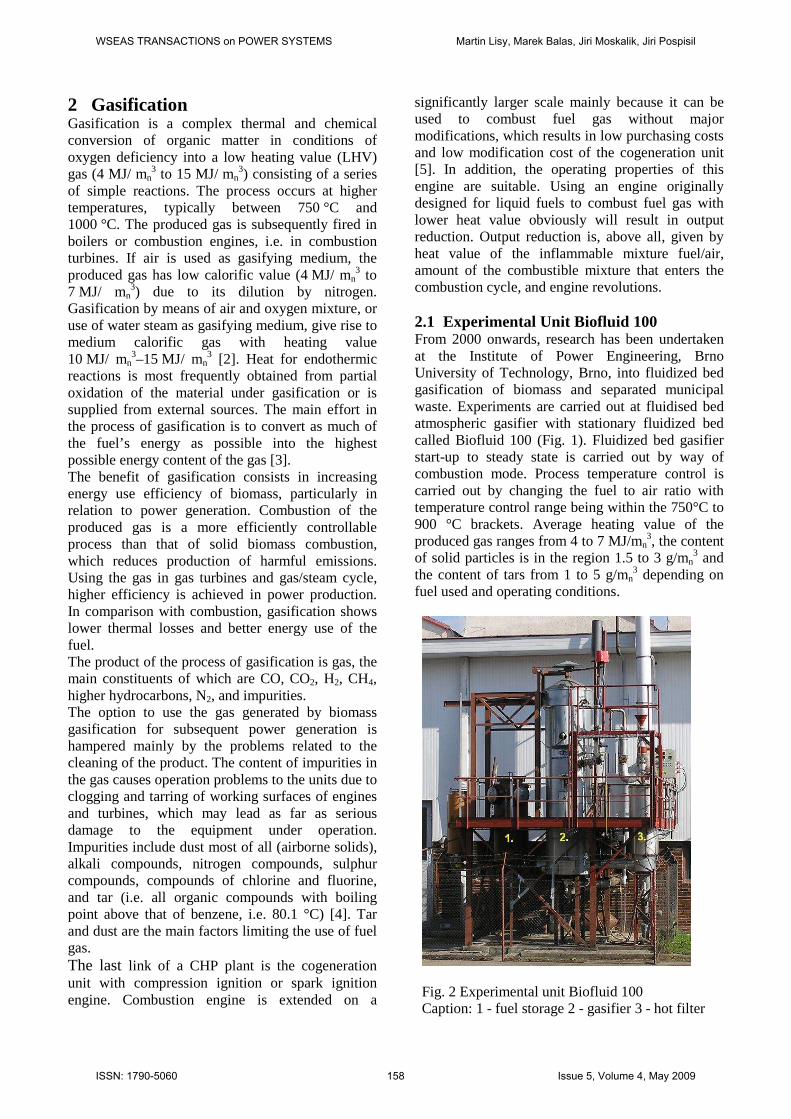
significantly larger scale mainly because it can be used to combust fuel gas without major modifications, which results in low purchasing costs and low modification cost of the cogeneration unit [5]. In addition, the operating properties of this engine are suitable. Using an engine originally designed for liquid fuels to combust fuel gas with lower heat value obviously will result in output reduction. Output reduction is, above all, given by heat value of the inflammable mixture fuel/air, amount of the combustible mixture that enters the combustion cycle, and engine revolutions. 2.1 Experimental Unit Biofluid 100 From 2000 onwards, research has been undertaken at the Institute of Power Engineering, Brno University of Technology, Brno, into fluidized bed gasification of biomass and separated municipal waste. Experiments are carried out at fluidised bed atmospheric gasifier with stationary fluidized bed called Biofluid 100 (Fig. 1). Fluidized bed gasifier start-up to steady state is carried out by way of combustion mode. Process temperature control is carried out by changing the fuel to air ratio with temperature control range being within the 750°C to 900 °C brackets. Average heating value of the produced gas ranges from 4 to 7 MJ/mn
3, the content of solid particles is in the region 1.5 to 3 g/mn
3 and the content of tars from 1 to 5 g/mn
3 depending on fuel used and operating conditions.
Fig. 2 Experimental unit Biofluid 100 Caption: 1 - fuel storage 2 - gasifier 3 - hot filter
WSEAS TRANSACTIONS on POWER SYSTEMS Martin Lisy, Marek Balas, Jiri Moskalik, Jiri Pospisil
ISSN: 1790-5060 158 Issue 5, Volume 4, May 2009

Fuel comes from rake-equipped storage tank to be fed to the gasifier in batches by worm conveyor. Blower-compressed air is delivered to the gasifier, to under its grate, as primary air ensuring partial oxidization of fuel and maintaining the fluidized bed. Moreover, air can be supplied at two other levels as secondary air and tertiary air. In a cyclone, the produced gas is rid of particulates and consequently combusted by a burner equipped with a small stabilizing natural gas fired burner with its own air inlet. Ash from the gasifier is discharged to ashbin on intermittent basis by means of a purpose-designed special moving grate. To be able to examine impact of air preheating, electric heater has been installed at the back of the blower. The parameters of the gasifier are as follows:
• Output (in generated gas) 100 kWt • Input (in fuel) 150 kWt • Fuel consumption max. 40 kg/h • Air flow max. 50 mn
3/h The type of fuel to be used is limited, primarily, by the size of the fuel worm conveyor and then by moisture content. Optimum moisture content is from 20 % to 30 %. Wood biomass mostly consists of shavings or small wood chips, their size being 2 cm to 3 cm. Herbaceous biomass either mostly consists of finely chopped matter or smaller size pellets. Chopped matter did not prove to be much of a success as there are major problems with fuel feeding, particularly with crust formation in the fuel storage bin. Neither is this type of fuel treatment optimal for formation of fluidized bed.
Fig. 3 Diagram of the experimental unit BIOFLUID 100 – 1 fuel storage, 2 gasifier, 3 cyclone, 4 hot dolomitic reactor, 5 protection bed, 6 nickel catalyst, 7 burner, 8 combustion engine. Caption of measured quantities: T101-103 – temperatures in the gas generator, T104 and T105 – temperatures under the cyclone, T106 – temperature in the cyclone, T107 – temperature of the inlet primary air, T108 – gas temperature at the outlet from the jacket, F 1-3 – air flows, F4 – gas flow, Pstat – outlet gas pressure, DP1 – fluidized bed pressure difference, Tin and Tout – temperatures on entrance and exiting to and out hot dolomitic reactor, DPf – hot dolomitic reactor pressure difference, T301-313 – temperatures in protection and nickel reactors, DPo and DPNi – protection and nickel reactors pressure difference.
WSEAS TRANSACTIONS on POWER SYSTEMS Martin Lisy, Marek Balas, Jiri Moskalik, Jiri Pospisil
ISSN: 1790-5060 159 Issue 5, Volume 4, May 2009
2.2 Methods of Measurement at Unit Biofluid 100 Gas quality measurement is usually carried out in two ways. One consists of an on-line monitoring of gas composition with simultaneous gas sampling to gastight glass sample containers. The samples are subsequently analysed using gas chromatograph. Tar sampling is carried out in line with IEA methodology [6] by capturing tar in a solution that is subsequently analysed by gas chromatograph with mass spectrometer. Presence of HCl, HF and NH3 in the gas is examined by their trapping in a NaOH solution. Operating parameters are monitored during operation and continuously recorded by the control computer. They include, in particular, mass flow of fuel, temperatures at various points of the unit, pressure difference in the fluidized bed, gas flow and pressure, and the temperature and flow of primary air.
3 Research Activities in the Area of Fluidized-Bed Gasification In the area of research, the Department of Power Engineering mainly focuses on the following:
• Processes of gasification of various kinds of wood and herbaceous biomass
• Primary methods of tar removal • Secondary methods of tar removal,
catalytically methods in particular. 3.1 Gasification of Various Kinds of Biomass In the area of research into the process of gasification proper, main focal point is gasification of herbaceous biomass and establishment of parameters of selected biofuels in relation to fluidized bed gasification. As biomass includes a broad range of biofuels, it cannot be seen as an entity, but each biofuel has to be standardized thoroughly as a number of their properties is significantly influenced by local or national conditions. This applies both to the composition of biofuels and operational and economic parameters of their use. Gasification of wood and/or municipal waste has already been technically mastered. However, gasification of the so-called herbaceous biomass is in its budding stage of research and development and much attention is given to it. Gasification of straw and other waste agricultural products, or possibly even of energy grasses, presents a
substantially greater technical problem as these plants usually contain larger amounts of nitrogen, sulphur, chlorine, and alkalis. To facilitate use of biomass in the Czech energy policy, a project named “Energy Parameters of Biomass” was launched thanks to co-operation of several research and private institutions. The aim of the project is to compile a database of the most promising kinds of biomass available in this country and to set basic fuel characteristics and operating parameters at combustion, fluidized gasification and fixed bed gasification. The following three main categories of biomass have been identified: woody plants, culm plants and miscellaneous biomass (wastes). Based on distribution of individual kinds of biofuels in CR, 15 typical kinds of biomass have been selected to have their energy properties defined. In each of the fuels proximate analysis, ultimate analysis and biochemical analysis are carried out, ash composition is given and characteristic temperatures of ash matter are specified. It became obvious from individual experiments that there is substantial difference between gasification of woody plants and gasification of culm plants. In woody plants, all the courses were steady. Operation of the reactor did not require any major operation interventions. The course of gasification of culm plants was the very opposite. Generally, the problem of gasification of non-woody biomass can be summed up in several basic points. The main problem is the low temperature of softening and sintering of ash matter of some of the kinds of herbaceous biomass. Furthermore, it is necessary to pay great attention to fuel treatment. Experiments that were carried out show that ordinary chopped straw is not suitable for use in fluidized bed gasifiers. Combination of these two factors results in considerable instability of gasification, which leads to poor gas quality and, above all, clogging of the reactor or, in the worst case, melting of fuel in the reactor. Examples of “problematic” crops include, e.g., cereal or rape straw, maize or tow. Last but least, problems may also arise due to higher proportions of chlorine, sulphur or alkali metals that may cause corrosion. Latest results, however, indicate that with suitable treatment of fuel and minor design modifications of the current reactor it will be possible to gasify even these problematic crops. Detail results from the project were published in monographic “Energy Parameters of Biomass”, which is accessible on website www.oei.fme.vutbr.cz [7].
WSEAS TRANSACTIONS on POWER SYSTEMS Martin Lisy, Marek Balas, Jiri Moskalik, Jiri Pospisil
ISSN: 1790-5060 160 Issue 5, Volume 4, May 2009
4 Gas Cleaning Methods As already mentioned above, removal of tar and dust from the fuel gas is a pivotal issue to use this gas in combustion engines. The area of dust removal from gases is already relatively well studied; however, if apart from dust also tar is present, then things get more complicated. There are several methods of tar removal; we shall focus on the catalytical ones. 4.1 Dust Removal Methods High temperature processes that do not waste the heat contained in the gas seem to be most advantageous in removal of solid particles from the generated gas. Moreover, there is no condensation of vapours and tar on pipe walls and there is no fouling of the equipment. The dust-free gas may then – with no additional heating – be cleaned for high temperature tar removal. Barrier filters can effectively be used to remove dust from gas at high temperatures. These filters operate on the basis of separation of dust particles from the gas on porous plate permeable for gas. The size of the particles and hence the effectiveness of filtration directly depend on the size of the pores. Practical application is by way of ceramic tubular filters, filters consisting of a layer of granular material etc. These filters can be operated at temperatures up to 650 °C, but are sensitive to the presence of alkali metals in the gas. Another disadvantage of these filters is the relatively high pressure loss, which even gets higher during operation due to the blinding of the filtration material pores. 4.2 Primary Methods of Tar Degradation Primary methods include measures applied within the reactor. They are very significant from operational point of view as they increase overall efficiency of energy conversion and, at the same time, reduce the need to remove tar by subsequent measures. One of the ways is application of catalyst straight to the fluidized bed of the generator. Using suitable material with catalytic and adsorption properties may result not only in reduced tar content, but also in reduced concentration of the undesirable compounds of sulphur and chlorine in the gas. Olivine and dolomite seem to be the most suitable materials. An intensive abrasion of particles of adsorbent occurs in the fluidized bed, small particles emerge with large surface and considerable adsorption activity.
4.3 Secondary Methods of Gas Cleaning Out of the host of secondary measures for elimination of tar content in the gas, our team focused on methods using catalytic reactions of tar cracking. The most frequently used catalysts include either natural catalysts (dolomite, olivine, zeolite, calcite), or metal-based (Ni, Mo, Co, etc.) catalysts. Both have their pros and cons. Non-metallic catalysts and the metallic ones as well are used to reduce the amount of tar contained in the product of gasification (gas) in separate reactors with fixed bed. They are referred to as secondary catalysts. The most frequently used non-metallic (natural) catalyst is dolomite – calcium magnesium carbonate. Calcinated dolomite used as catalyst for tar destruction following biomass gasification is subject of long-term examination. A number of institutions in the world carry out research into its application and its industrial application have already been devised. It is obvious from a majority of studies that dolomite is a very effective catalyst in tar cracking and its benefits also include the fact that it is relatively cheap and available. Dolomite is a calcium magnesium ore with chemical formula CaMg(CO3)2. At elevated temperatures, calcination occurs, carbonates turn to oxides, which results in CO2 release. The course of calcination depends on the following factors: temperature, grain size, dolomite composition, speed of heating and ambient atmosphere, particularly partial pressure of CO2 [8, 9]. At temperatures exceeding 600 °C and at the presence of CO2 the less stable MgCO3 gets decomposed. It is obvious that calcination temperature of MgCO3 as constituent of dolomite is higher than that of pure magnezite [10]. At higher temperatures, even CaCO3 gets calcinated. With growing content of CO2, the calcination temperature of CaCO3 moves towards higher values. Calcinated dolomite exhibits high activity in tar cracking, particularly at temperatures in excess of 850 °C. A mechanism of reforming of tar on dolimite is described in (1) and (2).
( ) 2323 COMgOCaCOCOCaMg ++→ (1)
23 COCaOCaCO +↔ (2)
To remove tar from gas, one can also apply metallic catalysts that are used in petrochemical industry for oil and natural gas reforming to syngas, for CO2 removal, for production of hydrogen for fuel cells and so forth. The commonest metal-based catalyst is nickel coated on a variety of carriers (alumina or alumina silicates) [11].
WSEAS TRANSACTIONS on POWER SYSTEMS Martin Lisy, Marek Balas, Jiri Moskalik, Jiri Pospisil
ISSN: 1790-5060 161 Issue 5, Volume 4, May 2009
Usage of nickel catalysts results in higher content of H2 and CO in the gas, methane and higher hydrocarbons are reduced or removed. Some studies show that nickel also reduces amounts of NH3 in the gas. Commercial nickel catalysts can be divided into two groups:
• Pre-reforming catalysts operating at lower temperatures (around 450 °C – 500 °C)
• Reforming catalysts operating in the range 750 °C – 900 °C.
A simplified mechanism of catalytic reforming of tar is described in detail in literature [12]. First, methane, or other hydrocarbon, is separated by adsorption on the active centres of nickel where hydrogen fission begins. Water is separated by adsorption on a ceramic carrier, hydroxylating the surface. At suitable temperature, OH radicals migrate to the side of the metal, take control over the oxidation of fragments of medium hydrocarbons and surface carbon to CO and H2. We can complete process describe equations (3) to (7):
22 2**2 H
xmHCHC xnmn
−+−→+
(3)
nxxnxn CHHCnHC **** 212 −+−→+− ′− (4)
( )*12
** 2 +++→−+− nHx
COOCH nx
(5)
22 ** HOOH +−↔+ (6)
*2*22 −↔+ HH (7) * is active centre of catalyst. The main advantages of metallic catalysts consist in the possibility to use them even at lower temperatures and their several times higher activity, which makes it possible to use smaller amounts or catalysts to clean the gas and thus to use smaller and more compact facilities (in comparison with e.g. dolomite). The disadvantage of metallic catalysts is their relatively great tendency to get de-activated. De-activation can be caused by:
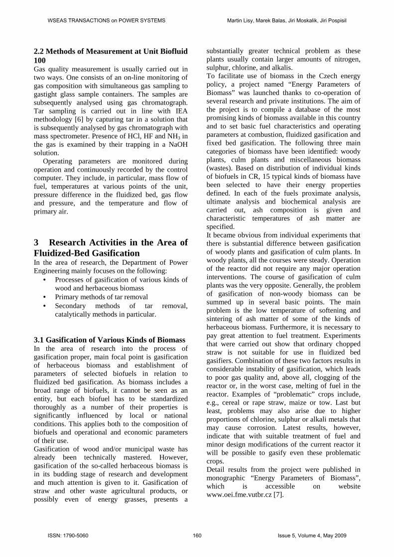
• Blocking of active centres of the catalysts due to coking – an effect of reactions on the surface of the catalyst with high tar content in the gas. The speed of de-activation can be reduced by raising the ratio steam/carbon in the fuel or by modification of surface reactions due the presence of some other metal [13, 14].
Fig. 4 System of formation whiskery carbon at nickel cristal
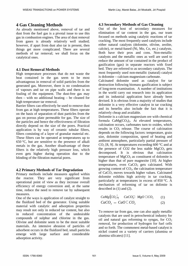
• Catalytic poisons (H2S) or substances
blocking the porous system of the catalyst (alkali metals, SiO2). Temperature is an important factor of the rate of de-activation by sulphur – catalysts get more tolerant to sulphur compounds with growing temperatures [15].
Fig. 5 Scheme of blocking the porous system of the catalysts by sulphur
• Irreversible changes in the system
carrier/catalyst (caking, sintering) – nickel crystals grow in size, which results in reduced surface area and consequently reduced activity of the catalyst. Resistance to sintering is increased by proper selection of carrier [16].
5 Methods of Gas Cleaning at experimental unit Biofluid 100 The brunt of the research into fluidized bed gasification at FME BUT is on the problem of fuel gas cleaning, tar removal in particular. As overwhelming majority of industrial applications used wet methods of fuel gas cleaning, the first cleaning tests were carried out using water scrubber and oil scrubber. The disadvantage of the systems with gas scrubber is reduction of overall efficiency of the device by wasting heat by direct cooling of
WSEAS TRANSACTIONS on POWER SYSTEMS Martin Lisy, Marek Balas, Jiri Moskalik, Jiri Pospisil
ISSN: 1790-5060 162 Issue 5, Volume 4, May 2009

gas. Another disadvantage is pressure loss, low efficiency of tar mist elimination in some types of scrubbers, consumption of scrubbing medium, and the necessity to treat waste water saturated with tars. After the primary tests with water scrubbing, attention was focused on methods making use of catalytic tar reduction. The most frequently used catalysts are either natural catalysts (dolomite, olivine, zeolites, and calcite) or catalysts based on metals (Ni, Mo, Co, etc.). Both options have their pros and cons. Non-metallic and metallic catalysts as well, are used to reduce the amount of tar contained in the product of gasification (gas) in separate reactors with fixed bed. They are referred to as secondary catalysts. The most frequently used nonmetallic (natural) catalyst is dolomite – calcium magnesium carbonate. In 2004, a continuously operating hot catalytic filter with fixed inclined dolomite bed was installed on the stand. Rolling out now is also the research into the possibility to clean gas by pre-reforming metallic catalysts. 5.1 Natural Catalysts Calcinated dolomite used as catalyst for tar removal from gasified biomass has been subject of long-term examination. It is obvious from majority of the studies that dolomite is a very effective catalyst for decomposition of tar and its benefit consists also in its being relatively inexpensive and available [8, 9, 10] 5.1.1 Primary Measures In experiments carried out in our Institute, dolomite and quartz sand were used that are easily available in the Czech Republic. Optimum temperature conditions for the use of these catalysts are somewhere around 850 °C. Efficiency of quartz sand is low at these temperatures; however, the presence of sand in the fluidized layer resulted in its high stability and higher gas quality. Application of dolomite in the fluidized bed of Biofluid 100 resulted in up to 60 % drop of original output concentration of raw gas from the generator. Though this is a positive result, it involves the necessity of taking secondary measures to fully clean the gas to the cogeneration unit. Mean values can be found in Table 1.
Table 1: Tar content table prior to primary measures and following their deployment
Tar content [mg/mn3] Working
condition without inert with inert Efficiency
dolomite 2032 805 60.5 % silicia sand
1894 1124 39.5 %
5.1.2 Hot Dolomitic Reactor From the very beginning, the design of the pilot plant hot dolomitic reactor (HDR) has been aimed at development of a functional industrial technology. To achieve that, it was necessary to eliminate a number of design and operation problems. The most difficult task was to ensure long-term operation and removal of passivated catalyst. This is accomplished by means of a specially designed two-segment rotary grate.. Main dimensions (∅ = 0.25 m and height 2 meters) were designed in line with expected flow of gas and expected loss of pressure.
a) b) Fig. 6 a) Scheme of hot dolomitic reactor, b) cross section of dolomite bed in HCF Caption: 1 - silo for clean granular material, 2 - isolated valve, 3 - reactor, 4 - cooling isolated chamber for dirty granular material, 5 - electric oven, 6 - rotary grate, 7 - thermal insulation
WSEAS TRANSACTIONS on POWER SYSTEMS Martin Lisy, Marek Balas, Jiri Moskalik, Jiri Pospisil
ISSN: 1790-5060 163 Issue 5, Volume 4, May 2009

The filter is heated electrically with power input 25 kW. This kind of heating is currently being replaced by partial combustion of fuel gas directly in HDR. Air inlets are at three points in the area of the grate. The ongoing oxidation is expected to remove deposited soot and ash. The overall design of the HDR is obvious from Fig. 6 Fresh dolomite is fed from vessel 1 equipped at its inlet and outlet by periodically switched slide valves 2. Reactor 3 is a cylindrical vessel with rotary grate 6 at its bottom removing passivated filling to vessel 4 that, too, has periodically switched slide valves 2 at its inlet and outlet. Gas is brought to the bottom part of the reactor, then flows upwards through the catalytic bed and leaves the reactor at its upper part. The reactor is fitted with electric heating 5 and air supply. Read-outs are taken of HDR pressure loss, three temperatures along the height on outer side of the wall that control the operation of electrical heating, and four temperatures along the height in the axis of the reactor, temperature of the gas at its inlet and outlet, gas flow, pressure and temperature of gas at its outlet. The HDR mainly serves for removal of tar that is the biggest problem in subsequent energy use of the gas. The HDR also traps dust particles contained in the produced gas. Various kinds of dolomite are used. All the tested materials have shown good efficiency in tar removal, but some of them have low abrasion resistance and low spalling resistance. The content of tars at HDR outlet ranges from 10 g/ mn
3 to 40 g/ mn3 and the content of dust from
10 g/ mn3 to 70 g/ mn
3 depending on operating conditions. The dust trapped behind the HDR contains more than 90 % particulates from dolomite. This dry dust can be removed from the tar-free gas by standard cloth filters. The figures depict temperature profile in HDR axis at optimum mode of operation (gas flow 25 mn
3/ hr.) - Fig. 7 - and efficiency of tar removal in relation to average temperature of the dolomite bed - Fig. 8. Maximally efficiency of tar removal amounts as high as 99.7 %. Table 2: Tar content at inlet and outlet of dolomitic reactor
Tar content [mg/mn3] Work temperature before after
Efficiency
790 °C 1227 68 94.5 % 850 °C 1408 31 98.0 % 905 °C 1544 20 98.7 %
Fig. 7 Depict temperature profile in HDR
Fig. 8 Efficiency of tar removal 5.2 Nickel Catalyst Research on use of metallic catalysts for cleaning fuel gas is in its budding stage at the Faculty of Mechanical Engineering (FME). Based on an extensive literature search, it was decided to focus oneself on pre-reforming catalysts for reasons of lower operating temperatures. The functionality of the selected method is verified on laboratory equipment, which, however, uses real gas. In general, it can be said that use of nickel catalysts for the cracking of tar is a realistic road to clean fuel gas.
Fig. 9 The pieces of nickel catalysts after experiments
WSEAS TRANSACTIONS on POWER SYSTEMS Martin Lisy, Marek Balas, Jiri Moskalik, Jiri Pospisil
ISSN: 1790-5060 164 Issue 5, Volume 4, May 2009

It is obvious from experiments on metallic catalysts that tar reduction in fuel gas is possible with high level of efficiency. Experiments were carried out for different temperatures under constant conditions (amount of catalyst, volume of passing gas, HCF, and generator mode) and gas and tar sampling was carried out using the same methods. Efficiency exceeding that given in Table 3 was achieved, too, but under substandard conditions. Further increase of efficiency is subject of further research. Table 3: Tar content at inlet and outlet of nickel filter
Tar content [mg/mn3] Work temperature before after
Efficiency
358 °C 4565 700 84.66 % 513 °C 1334 746 44.09 % 535 °C 759 260 65.72 % 563 °C 698 257 63.08 % 623 °C 376 76 79.57 % 633 °C 1001 147 85.26 %
Table 4: Average gas composition before and after dolomite filter (space velocity 2000 h-1, average temperature in bed 550 °C)
Content % vol. Component
Before filter After filter CO2 [%] 13,12 7,67 H2 [%] 16,94 27,56 CO [%] 7,23 16,03 CH4 [%] 4,08 0,15 N2 [%] 55,95 46,24 CxHy [%] 1,96 0,04 HHV [MJ.m-3] 6,32 6,53 Total Tar [mg.m-3] 1017,1 56,5
6 Conclusion The Czech Republic pays considerable attention to the development of renewable energy sources. The research work undertaken at the Institute of Power Engineering of The Brno University of Technology in the area of fluidized bed gasification of biomass and waste is aimed at higher use of modern units with electric output in excess of about 1 MW in decentralized supply of heat and power to regions. Thanks to state grants there is much interest in these sources in the CR. The main technical problem can be seen in the quality of the gas for combustion engine. Experimental researches, the results of
which have been summarized in the present paper, give prerequisites for early introduction of this promising technology in practice. The work has been financially supported by the Ministry of Education, Youth and Sport of Czech Republic in the frame of project MS1350031 „Waste and Biomass Utilisation focused on Environment Protection and Energy Generation“, and FV FSI BD 1383005. References: [1] Pospisil, J., Fiedler, J., Skala, Z.: Cool
Producing Systems Based on Burning and Gasification of Biomass, [online] Available: http://www.wseas.us/e-library/conferences/2006elounda2/papers/538-163.pdf
[2] Bridgwater, A. V.: The Technical and Economic Feasibility of Biomass Gasification for Power Generation. Energy Research Group, Aston University, Birmingham, (1995) Fuel Vol.74 -No. 5
[3] Ochrana L., Skála Z., Dvořák P., Kubíček J., Najser J.: Gasification of Solid Waste and Biomass, VGB Power Tech, Vol. 84, No. 6, 2004, p. 70-74. ISSN 1435-3199
[4] Neft, J. P. A. at al: Guideline for Sampling and Analysis of Tar and Particles in Biomass Producer Gases. Energy project ERK6-Ct199-2002 www.tarweb.net
[5] Pospisil, J., Fiedler,J., Applicability of Tri-generation Energy Production for Air-conditioning Systems in Czech Republic, [online] Available: http://www.wseas.us/e-library/conferences/2007athensmech/papers/565-140.pdf
[6] Van Paasen, S.V.B et al.: Guideline for Sampling and Analysis of Tar and Particles in Biomass Producer Gases. Final report documenting the guideline, R&D work and dissemination 2002, ECN-C-02-090
[7] Skála, Z., Ochodek, T.: Biomass energy parameters. VŠB-TU Ostrava, 2007, 91 str. ISBN 978-80-248-1615-9 [online] http://oei.fme.vutbr.cz/enparbio.pdf
[8] Shorter Communications: Predicting the rate of thermal decomposition of dolomite, Chemical Engineering Science, Vol. 51, No. 23, 1996, pp. 5229 -5232, ….
[9] Wiedemann H.G., Bayer, G.: Note of the thermal decomposition of dolomite, Thermochimica Acta, Vol. 121, 1987, pp.479 – 485.
WSEAS TRANSACTIONS on POWER SYSTEMS Martin Lisy, Marek Balas, Jiri Moskalik, Jiri Pospisil
ISSN: 1790-5060 165 Issue 5, Volume 4, May 2009

[10] Boyton R.S.: Chemistry and Technology of Lime and Limestone, Willey, N.York, USA, 1980.
[11] Abatzoglou, N., Dalai, A., Gitzhofer, F.: Green Diesel from Fischer-Tropsch Synthesis: Challenges and Hurdles [online] Available: http://www.wseas.us/e-library/conferences/2007creteeeesd/papers/562-097.pdf
[12] Ross, J. R. H., Steel, M. C. F., Zeni-Isfahani, A.: Evidence for the Participation of Surface Nickel Aluminate Sites in the Steam Reforming of Methane over Nickel/alumina Catalysts. Journal Catalyst, Vol. 52, 1978, pp. 280÷290
[13] Trimm, D. L.: Coke Formation and Minimization During Steam Reforming Reactions. Catalysis Today Vol. 37, 1997, pp. 233÷238
[14] Rostrup-Nielsen, J. R.: Industrial Relevance of Coking. Catalysis Today Vol. 37, 1997 pp. 225÷232
[15] Zhang, Y., Draelants, D. J., Engelen, K., Baron, G. V.: Improvement of Sulphur Resistance of a Nickel-modified Catalytic Filter for Tar Removal from Biomass Gasification Gas. Journal of Chemical Technology & Biotechnology, Vol. 78, 2003, pp. 265-268,
[16] Bengaard, H. S. at al: Steam Reforming and Graphite Formation on Ni Catalyst. Journal of Catalysis, Vol. 20, 2002, pp. 209-215
WSEAS TRANSACTIONS on POWER SYSTEMS Martin Lisy, Marek Balas, Jiri Moskalik, Jiri Pospisil
ISSN: 1790-5060 166 Issue 5, Volume 4, May 2009