atomistic investigation of gfrp composites under chloride
TRANSCRIPT

Special Issue Article
Advances in Structural Engineering1–12� The Author(s) 2020Article reuse guidelines:sagepub.com/journals-permissionsDOI: 10.1177/1369433220961749journals.sagepub.com/home/ase
Atomistic investigation of GFRPcomposites under chlorideenvironment
Xing Quan Wang1 and Denvid Lau1,2
AbstractFiber reinforced polymer composites have paved the way for the evolution of the engineering materials. Glass fiber reinforced polymer(GFRP) has become one of the most promising materials among the novel composites due to its low price and high performance.Here, the GFRP composite in investigated by fill atomistic molecular dynamics, which contains the epoxy matrix and amorphous silicasubstrate. The degradation in chloride environment is revealed through the interfacial interactions, the structural changes of the epoxymatrix and hydrogen bonding in the composites. Compared to dry and aqueous environment, the simulation results show that chlor-ide environment leads to the worst deterioration of interfacial adhesion, which correlates with structural and mechanical degradationof bonded interface, as indicated by the decreased epoxy density close to interface. It is indicated by examining the nano-structures ofthe interface during the pulling process that the chloride environment hinders the formation of intramolecular and intermolecularhydrogen bonds in the GFRP composites. These findings indicate the deterioration towards bond and matrix is critical in the presenceof the chloride environment, which provides the fundamental insight for designing and predicting performance degradation of macro-scopic GFRP composites in the marine application.
Keywordspolymer-matrix composites, interface, chloride environment, molecular dynamics, hydrogen bond
Introduction
Molecular dynamics (MD) simulation has furnishedthe fundamentally quantitative investigation of chem-istry, physics, biology, and medicine from atomisticperspective (Durrant and McCammon, 2011; Karplusand Petsko, 1990; Yusupov et al., 2013). Starting witha successful calculation of interacting classical particlesin the late 1950s, blossoming with the third evolutionof computing power improvement, extraordinaryachievements in material science (Alder andWainwright, 1957) have demonstrated through MDsimulation. MD simulation is based on the descriptionand prediction of interatomic behavior that can wellmimic the discrete and heterogeneous nature of thematerials at nano-scale, which is the basis of bottom-up approach. This characteristic of MD simulation isdifferent from that of numerical simulation under con-tinuous condition. This atom-based approach canovercome the inherent shortcomings of finite elementand meshless methods in small-scale simulations. Inrecent years, MD simulation is expected to show itspresence in civil engineering after spanning many
frontiers, so as to bring new inspiration and break-throughs to this traditional engineering industry.
Fiber reinforced polymer and cementitious materialscomposite reinforcements are two major civil engineer-ing materials in applications. Civil engineering materi-als are a mixture of natural materials and artificialmaterials such as cement, coarse aggregate, fine aggre-gate, and reinforcement to improve all aspects of mate-rial performance, including durability, constructabilityand cost control. The observation, prediction, andimprovement of the bonding properties and interfacialproperties of various components (Wang et al., 2019)are explicitly significant to ensure the full transmission
1Department of Architecture and Civil Engineering, City University of
Hong Kong, Hong Kong, China2Department of Civil and Environmental Engineering, Massachusetts
Institute of Technology, Cambridge, MA, USA
Corresponding author:
Denvid Lau, Department of Architecture and Civil Engineering, City
University of Hong Kong, 83 Tat Chee Avenue, Kowloon, Hong Kong,
China.
Email: [email protected]

of force inside the material. However, the internalstructure complexity of concrete material cannot bepromulgated from the continuum mechanics based onthe classical fracture theories. Despite the quantifica-tion of the interfacial deterioration through classicalfracture mechanics by the measurement of the criticalfracture toughness, it cannot provide any actual insightof the failure process and actual deformation at thevicinity of debonding surface or interface crack (Guneset al., 2013). As the atomistic fundamental approach,MD simulation has been adopted for studying underly-ing properties and providing a deeper understanding ofthe macroscopic deformation and debonding insidesophisticated materials. The schematic diagram of thecomposites of Seawater Sea sand Concrete (SSC) andglass fiber reinforced polymer (GFRP) at multiplescales is as shown in Figure 1. With the application ofMD simulation in civil engineering field, the effects ofconfined water and cracking after loading can be inves-tigated through atomistic models of cement hydrationproducts (Pellenq et al., 2009). The properties enhance-ment by adding nano-additives into concrete can beinvestigated and predicted through MD simulations(Yu et al., 2016). Furthermore, the key issues in GFRPreinforced concrete, the debonding and crack propaga-tion mechanisms of fiber–matrix interface, can be stud-ied thoroughly at nano-scale level (Tam and Lau, 2015;Tam et al., 2017b).
The degradation of glass fibers/polymer interfaceunder chloride environment through MD simulation ispresented to discuss the mechanism of seawater corro-sion on GFRP rebar. GFRP rebar has been usedextensively in marine applications of civil engineeringas its better corrosion resistance compared with con-ventional rebar (Zhou et al., 2017). But still, a reduc-tion of GFRP performance is observed in the long-term seawater immersion (Zhou et al., 2018). As
seawater immersion is one of the momentous factorsleading to the premature failure of GFRP rebar, it isimportant to reveal how do the seawater immersionaffects the properties of GFRP rebar so as to enablefull realization of the potential of GFRP compositesunder corrosive conditions. Previous research(Karbhari and Navada, 2008) has focused on experi-mental detection and structural analysis based on tra-ditional continuum theory under different serviceconditions. The acquisition of this empirical data set isthe basis of macro-scale modeling. However, this leadsto the unavoidable defect at the same time, which isthe incapability to predict the initial behavior of inter-face degradation and explore the fundamental reasonof performance reduction. Some pioneering MD simu-lations (Buyukozturk et al., 2011; Jian and Lau, 2019,2020; Lau et al., 2014; Yaphary et al., 2017) focusedon exploring the properties of different materials, suchas polymer and carbon structures. While the researchon the mechanism of debonding and debonding on thefull atomistic model is still lacks. This paper enrichesthe research on the origin of debonding betweenorganic and non-organic materials and also illustratesthe important concepts and ideas in the civil engineer-ing application of MD simulation through the casestudy of the GFRP atomistic model.
This paper aims to provide a comprehensive andtechnical illustration on the application of moleculardynamics in the civil engineering field. Taking GFRPbars as an example, the atomic modeling is performedand its degradation mechanism in the chloride environ-ment is analyzed and elaborated. The model consiststhe full atomistic interfacial structures of GFRP rebar,which glass fiber and epoxy matrix are included. Tocharacterize the degradation of the glass fiber/epoxyinterface, the adhesion energy, mechanical propertiesand the structural evolution of chloride-immersed case
Figure 1. Schematic diagram of SSC-GFRP composites at multiple scales: (a) the macroscale composite sample and glass fiber/epoxy interface; (b) the microscale glass fiber/epoxy interface, which is the critical region of structural deterioration underenvironmental exposure; and (c) the nanoscale epoxy molecules bonded to amorphous silica.
2 Advances in Structural Engineering 00(0)

are measured and compared with the pure-waterimmersed case and dry case. Moreover, the segmentaldynamics of the glass fiber/epoxy interfacial model arequantified to reveal how chloride ions affect the move-ments of epoxy chains. Through the energy profile, thedebonding analysis and degradation characterizationof GFRP rebar, this paper presents the potential andability of MD simulations in the application of numeri-cal calculations and predictions in civil engineering. Itis of great significance to introduce MD simulation tothe construction industry.
Computational methods
The research approach used in this research involvedthe construction of the atomistic interfacial model rep-resented the interface between glass fiber and epoxymatrix. Dry, aqueous and chloride salt environmentsare included in the simulated service environment byconditioned the interfacial model in the vacuum,water, and sodium chloride solution. Through theseparation process between fiber and matrix, the inter-action energy of the bonded interface with differentenvironment exposure is calculated. The structural andmechanical behavior are also recorded. The detailedconstruction process and simulation of the atomisticmodel are provided in following sections.
Atomistic model
The construction of atomistic model contains the selec-tion of modeling software and forcefield andmolecular-level restore of interface. The open sourcecode Large-scale Atomic/Molecular Massively ParallelSimulator (LAMMPS) is used in this research(Plimpton and Hendrickson, 1995). In this paper, allthe atomistic models are described using consistentvalence forcefield (CVFF) considering it its capabilityhas been proved in the simulation of silica and epoxy(Tam et al., 2017a, 2017b; Yaphary et al., 2017). Fornon-bonded interaction, the van der Waals (vdW)interaction between glass fiber and epoxy matrix issimulated by using a truncated Lennard-Jones (LJ)12–6 potential. The long-range electrostatic interactionis treated by using the particle-particle-particle-mesh(PPPM) solver with the accuracy of 1024.
The atomistic model presents the interface betweenglass fiber and epoxy matrix contains two parts. Theepoxy resin used in this work is obtained by cross link-ing diglycidyl ether of bisphenol A (DGEBA) andtriethylenetetramine (TETA), which is the basic struc-ture of epoxy resin used in GFRP fabrication. The sizeof modeled epoxy structure is 5.2 nm 3 5.2 nm 3
5.9 nm. The crosslinking procedure of the epoxy modelis automatically achieved through algorithm. The
crosslinking algorithm is described as following proce-dure: The reactive atoms of monomers and cross-linkers located within the reaction radius are firstlymanually marked. Then, the recognized reactive atomsare broken and the recognized reactive atoms arebonded to form crosslinks. In this algorithm, the cross-linked structure is equilibrated every time before enter-ing the next crosslinking procedure. Each reactivegroup stepwise looks for the matching crosslinkingreactive group within a distance of 3 A to 10 A with anincrement of 0.5 A. The modeled epoxy structure hasthe crosslink density of 94% with the elastic modulusof 4.73 GPa and Poisson’s ratio of 0.33. The elasticproperties which and the cross-link density have closeagreement with various literatures and experimentalmeasurments (Hirschl et al., 2013; Sindt et al., 1996).The glass fiber is simulated by the atomistic model ofamorphous silica since amorphous silica is the majorcomponent of glass fiber and has a better description ofthe surface interactions such as hydrogen bond (H-bond) in reality. Meanwhile, compared with the crystal-line silica, the atomistic model of amorphous silica hasa better description of density, mechanical strength,and thermal conductivity of the glass fiber. The con-struction of the amorphous silica model is generated bythe crystalline silica model after it has been throughheating, melting and quenching process. Because of thenon-reactive forcefield applied in this research cannotmimic the bond formation and bond -breaking process,the spontaneous formation of the hydroxyl groups onthe silica surface cannot be expected. Therefore, afterthe quenching process, hydroxyl groups are manuallyadded on the silica surface to simulate the hydroxyla-tion in the industrial manufacturing process of the silicaafter the quenching process, following the equilibriumprocess under isothermal -isobaric (NPT) ensemble for0.5 ns. The final amorphous silica model has the size of10.5 nm3 10.5 nm 3 4 nm and has a density of2.2 g/cm3 which is consistent with the measurementfrom macroscopic experiment (Ebrahem and Markert,2017; Pedone et al., 2008).
Some small perturbation in the initial structure inthe process of the atomistic model construction may ormay not result in the significant change towards theresults. Those input model parameters that with vari-abilities belong to the external conditions and the con-figuration of the whole model including thedimensions, the ensemble, different initial velocity ofatoms, and different contact regions. The intrinsicproperties of atoms cannot be changed, such ascharges, atom types, equivalence, and bond properties.Although the cumulative errors can be generated innumerical integration, that can be minimized withproper selection of algorithms and parameters. Theeffect of the initial velocity of the atoms on the overall
Wang and Lau 3
simulation is reflected in the initial energy and tem-perature of the structure. This can be controlled andeliminated through relaxation steps and correspondingensembles. Ensembles perform time integration onNose-Hoover style non-Hamiltonian equations ofmotion which are designed to generate positions andvelocities and updates the position and velocity foratoms in every timestep. The sensitivity of ensemblescan be reflected by the molecular structure dumped atthe end of the timestep. Meanwhile, the dimensionsand the different contact regions at the surface of themodel can result in the changes in interfacial adhesionenergy. In addition, the wrong input modeling para-meters can lead to unreasonable simulation results,and even lead to the atomic structure out of control orcollapse during the simulation process. The propertiesof our initial model are consistent with the physicaland chemical properties obtained through the experi-mental measurements. Theoretically and practically,the energy and structure changes during the simulationare controllable and reasonable which both indicatesthe correctness of the input modeling parameters andresults.
Simulation details
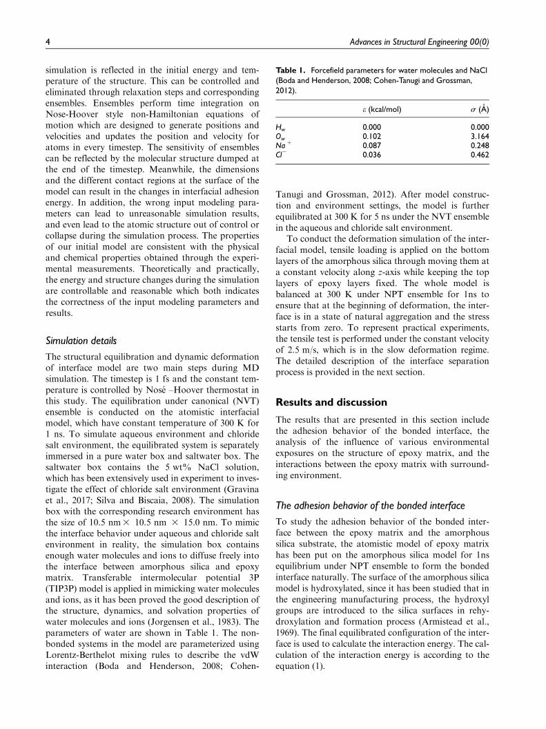
The structural equilibration and dynamic deformationof interface model are two main steps during MDsimulation. The timestep is 1 fs and the constant tem-perature is controlled by Nose –Hoover thermostat inthis study. The equilibration under canonical (NVT)ensemble is conducted on the atomistic interfacialmodel, which have constant temperature of 300 K for1 ns. To simulate aqueous environment and chloridesalt environment, the equilibrated system is separatelyimmersed in a pure water box and saltwater box. Thesaltwater box contains the 5 wt% NaCl solution,which has been extensively used in experiment to inves-tigate the effect of chloride salt environment (Gravinaet al., 2017; Silva and Biscaia, 2008). The simulationbox with the corresponding research environment hasthe size of 10.5 nm3 10.5 nm 3 15.0 nm. To mimicthe interface behavior under aqueous and chloride saltenvironment in reality, the simulation box containsenough water molecules and ions to diffuse freely intothe interface between amorphous silica and epoxymatrix. Transferable intermolecular potential 3P(TIP3P) model is applied in mimicking water moleculesand ions, as it has been proved the good description ofthe structure, dynamics, and solvation properties ofwater molecules and ions (Jorgensen et al., 1983). Theparameters of water are shown in Table 1. The non-bonded systems in the model are parameterized usingLorentz-Berthelot mixing rules to describe the vdWinteraction (Boda and Henderson, 2008; Cohen-
Tanugi and Grossman, 2012). After model construc-tion and environment settings, the model is furtherequilibrated at 300 K for 5 ns under the NVT ensemblein the aqueous and chloride salt environment.
To conduct the deformation simulation of the inter-facial model, tensile loading is applied on the bottomlayers of the amorphous silica through moving them ata constant velocity along z-axis while keeping the toplayers of epoxy layers fixed. The whole model isbalanced at 300 K under NPT ensemble for 1ns toensure that at the beginning of deformation, the inter-face is in a state of natural aggregation and the stressstarts from zero. To represent practical experiments,the tensile test is performed under the constant velocityof 2.5 m/s, which is in the slow deformation regime.The detailed description of the interface separationprocess is provided in the next section.
Results and discussion
The results that are presented in this section includethe adhesion behavior of the bonded interface, theanalysis of the influence of various environmentalexposures on the structure of epoxy matrix, and theinteractions between the epoxy matrix with surround-ing environment.
The adhesion behavior of the bonded interface
To study the adhesion behavior of the bonded inter-face between the epoxy matrix and the amorphoussilica substrate, the atomistic model of epoxy matrixhas been put on the amorphous silica model for 1nsequilibrium under NPT ensemble to form the bondedinterface naturally. The surface of the amorphous silicamodel is hydroxylated, since it has been studied that inthe engineering manufacturing process, the hydroxylgroups are introduced to the silica surfaces in rehy-droxylation and formation process (Armistead et al.,1969). The final equilibrated configuration of the inter-face is used to calculate the interaction energy. The cal-culation of the interaction energy is according to theequation (1).
Table 1. Forcefield parameters for water molecules and NaCl(Boda and Henderson, 2008; Cohen-Tanugi and Grossman,2012).
e (kcal/mol) s (A)
Hw 0.000 0.000Ow 0.102 3.164Na+ 0.087 0.248Cl2 0.036 0.462
4 Advances in Structural Engineering 00(0)

EIE =ES +EEpoxy � ES�Epoxy ð1Þ
where EIE denotes the interaction energy betweenamorphous silica substrate and epoxy matrix; ES
denotes total energy of amorphous silica; EEpoxy
denotes total energy of the epoxy matrix; ES-Epoxy
denotes the total energy of amorphous silica/ epoxysystem. The results are as shown in Figure 2. Thebonded interface processes the highest interactionenergy in dry environment. Compared with the dryenvironment, the adhesion energy in water-based envi-ronment decreased by 67.8%, and that in chloride envi-ronment decreased by 75.1% indicating the adhesionstrength has been further weakened by chloride ionscompared with the aqueous environment. As the non-bonding interactions contribute most of the interactionenergy, the energy of the van der Waals (vdW) andelectrostatic interactions are also recorded using thesame calculation principle of equation (1). The resultshows that the vdW interactions are the dominantsource of the interaction energy in three environmentalexposures. Specifically, as most of the hydrogen bond-ing is composed of electrostatic force, the modern (sec-ond-generation) popular forcefields has regarded theelectrostatic terms as hydrogen bonding terms in theanalysis between two neutral systems. The electrostaticinteraction energies take the 24.7%, 22.7%, and22.0% of the total interaction energy respectively,which demonstrate the changes of the interactionsof hydrogen bonding at the bonded interface.
To investigate the strong adhesion mechanismbetween epoxy matrix and the surface of the amor-phous silica in the dry environment, radial distributionfunctions (RDFs) between Osilica and Oepoxy, Nepoxy
are calculated. RDFs are as shown in Figure 3, whereOsilica presents the oxygen atoms in the hydroxylgroups at silica surface, Oepoxy and Nepoxy presents theoxygen and nitrogen atoms in epoxy matrix. The firstnoticeable peak in Figure 3(a) can be found in the 2.5
A and 3.0 A, which indicates the tightly attachmentbetween hydroxylated surface of the amorphous silicaand oxygen and nitrogen atoms in epoxy matrix.Hydrogen bonds are more appropriately referred to as‘‘special phenomena’’ involving a hydrogen atomlocated between a pair of other atoms having a highaffinity for electron with in the intermolecular range of2.0 A to 3.8 A. For interactions between oxygenatoms, hydrogen atoms and oxygen atoms, nitrogenatoms in the intermolecular distance of 2.0 A to 3.3 Awith the angle from 110� to 180� can be regarded asH-bond. The distance between Osilica and Oepoxy, Osilica
and Nepoxy are fall in the distance of the H-bond defi-nition (Martı, 1999). The atomic configurations of H-bond between amorphous silica substrate and epoxymatrix at interfacial region shown in Figure 3(a) indi-cates that H-bond play an important role in enhancingthe adhesion strength of amorphous silica and epoxymatrix. In the aqueous and chloride salt cases, due tothe intrusion of water molecules into the interface,additional types of H-bond are expected between theamorphous silica substrate and water molecules, whichpresent by the Hsilica and Owater, is the H-bond betweenhydrogen atom of hydroxylated surface and oxygenatom of water molecule. Hsilica-Owater present thehydrogen atom of hydroxyl group is the donor and theoxygen atom in water molecule is the acceptor,Osilica-Hwater present the hydrogen atom of water mole-cule is the donor and the oxygen atom of hydroxylgroup is the acceptor. In the aqueous environment, thefirst demonstrable peaks of Hsilica-Owater andOsilica-Hwater RDFs can be observed at intermoleculardistances of 2.1 A and 2.9 A. Those H-bond can bealso observed in the atomic configurations in Figure 3.While the RDFs of Hsilica-Owater and Osilica-Hwater
manifested two small peaks centered at intermoleculardistances of 1.8 A and 3.7 A under chloride environ-ment, suggesting that the H-bonds at epoxy/amor-phous silica interface are formed preferentially
Figure 2. The total energy, vdW and electrostatic interaction between epoxy matrix and amorphous silica in dry, aqueous, andchloride salt environment. The aqueous and chloride environment can greatly reduce the interfacial adhesion energy. The decreasedproportion of electrostatic interaction energies under aqueous and chloride indicates that the interface interaction has been changed.
Wang and Lau 5

through Hsilica-Owater H-bond in the aqueous environ-ment instead of the chloride environment. The firstpeak between Osilica-Hwater manifested in 3.7 A indi-cates hydrogen bond between Osilica and Hwater is notpreferentially to form in the chloride environment. Thechloride environment hinders the formation of H-bondcompared with the pure water system can be explainedthrough the concept of ‘mixed’ water-anion hydrogenbonded networks in the chloride environment. (Petheset al., 2020) The H-bond between the amorphous silicasurface and the water molecules firmly adsorbs thewater molecules on the surface, and the water mole-cules occupy the position of the epoxy matrix, thusfurther weakening the interface interaction.
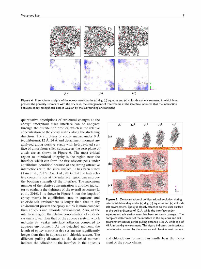
To further reveal the difference of the interfacialinteractions under different environmental exposure.The Connolly surface method is applied here to char-acterize the free volume, which identifies the unoccu-pied space in the structures qualitatively (Dong et al.,2014). In Figure 4, the free volume is presented by theblue area. The darker the color, the higher the vacuumis. Compare with the dry case, the enlargement of freevolume at the interface between epoxy and silicamatrix indicates that the interaction between epoxy-amorphous silica is weakened by the surroundingenvironment.
Nanostructure in epoxy matrix
Structural analysis of epoxy matrix under differentenvironmental exposures is related to the deteriorationof interfacial integrity. The configurational evolution
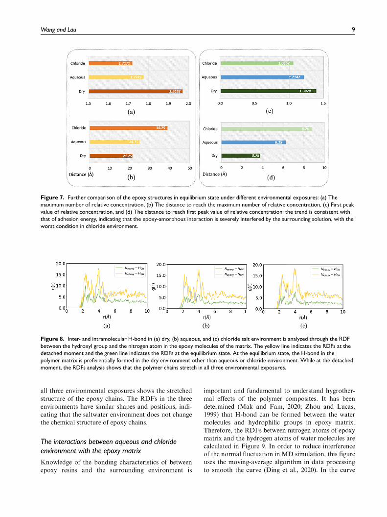
during interfacial debonding under dry, aqueous andchloride salt environment are depicted in Figure 5.From the demonstration of configurational evolutionin Figure 5, it can be seen that when the pulling dis-tance is 12 A, the epoxy matrix is closely attached tothe surface of the amorphous silica. Deformationmainly comes from the stretching of polymer chainsrather than interface deterioration, as there is no fail-ure between epoxy matrix and amorphous silica sur-face. However, the degradation of the interface occursmuch earlier than in the dry condition in the aqueousand chloride environment. The adsorption of epoxychains on the surface of amorphous silica surfacedecreased a lot when the pulling distance is 12 A. Thefailure of the interface indicates that the adhesive forceof the interface is not enough to support the smalldeformation and movement of epoxy chains. Whenthe pulling distance comes to 24 A, the contrast of thisinterface integrity is more obvious under the threeenvironments. The epoxy matrix in the dry environ-ment is still attached to the surface of the amorphoussilica, while the epoxy matrix in aqueous and salt envi-ronment is on the edge of complete detachment. Thecomplete detachment of the interface in the aqueousand salt environment occurs at the pulling distance is36 A, while it is of 48 A in the dry environment. Theserecorded configurational evolutions during interfacialdebonding demonstrate the deterioration of the inter-face caused by the aqueous and chloride environment.
The quantitative analysis of the structure can betterdistinguish the influence of the chloride salt environ-ment and the water environment on the interface. The
Figure 3. RDFs and H-bond structures of the interface in dry, aqueous and chloride salt environment. (a) In the dry system. RDFsbetween oxygen atoms in hydroxyls of amorphous silica and oxygen/nitrogen atoms in epoxy and interfacial H-bond structures onamorphous silica substrate. (b) In the aqueous system. RDFs between oxygen atoms in hydroxyls of amorphous silica and oxygen/hydrogen atoms of water and interfacial H-bond structures on amorphous silica substrate. These results indicates that in the dryenvironment, the polymer matrix and the surface form more hydrogen bonds to strengthen the interface interaction, while in thewater environment and the chloride salt environment, the surface and water molecules form H-bond to seize the position of epoxymolecules and weaken the interface interaction.
6 Advances in Structural Engineering 00(0)
quantitative descriptions of structural changes at theepoxy/ amorphous silica interface can be analyzedthrough the distribution profiles, which is the relativeconcentration of the epoxy matrix along the stretchingdirection. The sturctures of epoxy matrix under 0 A(equilibrium), 12 A, 24 A and detachment moment areanalyzed along positive z-axis with hydroxylated sur-face of amorphous silica substrate as the zero plane ofz-axis are as shown in Figure 6. The most criticalregion to interfacial integrity is the region near theinterface which can form the first obvious peak underequilibrium condition because of the strong attractiveinteractions with the silica surface. It has been stated(Tam et al., 2017a; Xia et al., 2014) that the high rela-tive concentration at the interface region can improvethe bonding strength of the interface. The maxmiumnumber of the relative concentration is another indica-tor to evaluate the tightness of the overall structure (Liet al., 2016). It is shown in Figure 6 that the length ofepoxy matrix in equilibrium state in aqueous andchloride salt environment is longer than that in dryenvironment present the epoxy matrix is more compactthan aqueous and chloride environment. Also, at theinterfacial region, the relative concentration of chloridesystem is lower than that of the aqueous system, whichindicates its weaker interface adhesion compared toaqueous environment. At the detached moment, thelength of epoxy matrix in dry system was significantlylonger than that in aqueous and chloride system. Thedifferent pulling distances at the detached momentindicate the adhesion at the interface in the aqueous
and chloride environment can hardly bear the move-ment of the epoxy chains.
Figure 4. Free volume analysis of the epoxy matrix in the (a) dry, (b) aqueous and (c) chloride salt environment, in which bluepresent the porosity. Compare with the dry case, the enlargement of free volume at the interface indicates that the interactionbetween epoxy-amorphous silica is weaken by the surrounding environment.
Figure 5. Demonstration of configurational evolution duringinterfacial debonding under (a) dry, (b) aqueous and (c) chloridesalt environment. Epoxy is closely attached to the silica surfaceat the pulling distance of 12 A, while the interface underaqueous and salt environment has been seriously damaged. Thecomplete detachment of the interface in the aqueous and saltenvironment occurs at the pulling distance is 36 A, while it is of48 A in the dry environment. This figure indicates the interfacialdeterioration caused by the aqueous and chloride environment.
Wang and Lau 7

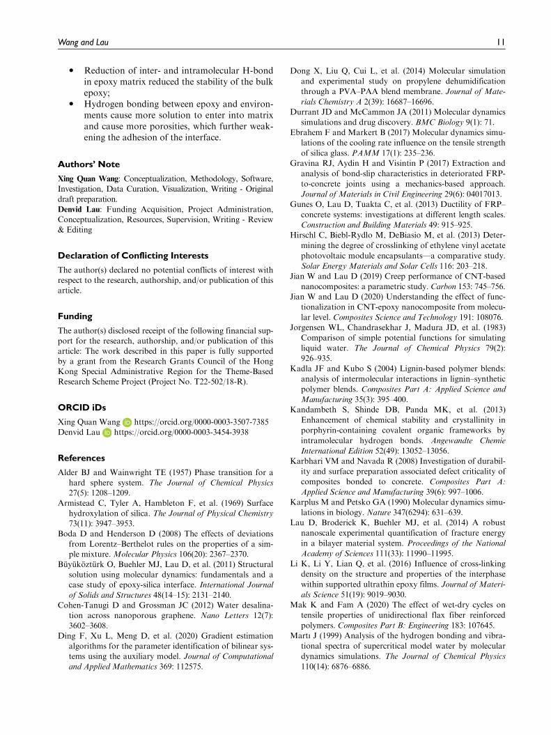
For the further comparison in equilibrium state ofdifferent environmental exposures, the maximumnumber of relative concentration and the first peakvalue of relative concentration in Figure 6(a) arerecorded in Figure 7. In Figure 7, among the dry,aqueous and chloride salt environment, the first peakvalue decreases, along with the increased distance toreach the peak shown in the further proved that thedry system processes the highest interfacial integrity.Compared with the dry environment, the maximumrelative concentration of epoxy matrix in water envi-ronment and chloride environment decreased by9.9% and 12.8% respectively. The first peak value ofepoxy matrix in water and chloride environmenttakes only 87.2% and 75.8% of that in dry environ-ment. These results further indicates that the watermolecules reduce the adhesion of the interface, chlor-ide ion will further weaken the interface adhesioncaused the decreases of the interfacial integrity inaqueous and chloride system, which also explainedwhy the chloride salt system processes the lowestinterfacial integrity.
Hydrogen bonds in epoxy matrix
Apart from the interfacial degradation, the presence ofaqueous and chloride environment also has the influ-ence on the inter- and intramolecular H-bond within
the epoxy matrix. The presence of intramolecular orintermolecular hydrogen bonds in the polymer matrixcan affect the glass transition temperature, physicalstability as well as thermal properties (Kadla andKubo, 2004; Kandambeth et al., 2013; Prinos andPanayiotou, 1995). In the epoxy matrix which arecrosslinked from the DGEBA and TETA, the H-bondbetween the hydroxyl group and the nitrogen atom inthe epoxy molecules is expected, so the RDFs betweenthese two types of atoms are calculated in Figure 8.The yellow line presents the RDFs under detachedmoment, the green line presents the RDFs under theequilibrium state. Under the equilibrium state, epoxychains naturally curled together with many otherchains around each chain in a very close range, result-ing in the high probability of forming hydrogen bondbetween chains. Therefore, the obvious peaks of RDFsare the superposition of molecules and intermolecularstructures that can present the inter- and intramolecu-lar H-bond. Two noticeable peaks can be observed inthe dry system which is nearly two times high of thepeaks in the aqueous and chloride salt system. Thisresult indicates the H-bond in the polymer matrix areformed preferentially in the dry environment otherthan in aqueous and chloride environments. While atthe detached state, the epoxy matrix structure is loose,the chain adjacent rarely occurs in the range of H-bond can be formed. Therefore, the RDFs analysis of
Figure 6. Relative concentration of epoxy atoms which is the quantitative descriptions of structural changes in the dry, aqueousand chloride salt environment (a) in the equilibrium state; (b) at the moment of stretch distance 12 A; (c) at the moment of stretchdistance 24 A; (d) at the detached moment.
8 Advances in Structural Engineering 00(0)
all three environmental exposures shows the stretchedstructure of the epoxy chains. The RDFs in the threeenvironments have similar shapes and positions, indi-cating that the saltwater environment does not changethe chemical structure of epoxy chains.
The interactions between aqueous and chlorideenvironment with the epoxy matrix
Knowledge of the bonding characteristics of betweenepoxy resins and the surrounding environment is
important and fundamental to understand hygrother-mal effects of the polymer composites. It has beendetermined (Mak and Fam, 2020; Zhou and Lucas,1999) that H-bond can be formed between the watermolecules and hydrophilic groups in epoxy matrix.Therefore, the RDFs between nitrogen atoms of epoxymatrix and the hydrogen atoms of water molecules arecalculated in Figure 9. In order to reduce interferenceof the normal fluctuation in MD simulation, this figureuses the moving-average algorithm in data processingto smooth the curve (Ding et al., 2020). In the curve
Figure 7. Further comparison of the epoxy structures in equilibrium state under different environmental exposures: (a) Themaximum number of relative concentration, (b) The distance to reach the maximum number of relative concentration, (c) First peakvalue of relative concentration, and (d) The distance to reach first peak value of relative concentration: the trend is consistent withthat of adhesion energy, indicating that the epoxy-amorphous interaction is severely interfered by the surrounding solution, with theworst condition in chloride environment.
Figure 8. Inter- and intramolecular H-bond in (a) dry, (b) aqueous, and (c) chloride salt environment is analyzed through the RDFbetween the hydroxyl group and the nitrogen atom in the epoxy molecules of the matrix. The yellow line indicates the RDFs at thedetached moment and the green line indicates the RDFs at the equilibrium state. At the equilibrium state, the H-bond in thepolymer matrix is preferentially formed in the dry environment other than aqueous or chloride environment. While at the detachedmoment, the RDFs analysis shows that the polymer chains stretch in all three environmental exposures.
Wang and Lau 9

after reducing the fluctuation, the value that exceedstwice the normal vibration amplitude can be regardedas the peak value. Two peaks can be observed atapproximately 0.2 nm and 0.3 nm in aqueous environ-ment, while there is no conspicuous peak in the rangeof 0.2 nm to 0.3 nm in chloride environment, whichindicates the interaction between epoxy matrix and sur-rounding solution in the aqueous environment is stron-ger than the interaction in the chloride environment.
This result shows that the chloride salt can weakenthe interaction between the epoxy substrate and thewater molecules, which is consistent with the results inthe previous sections. This phenomenon is correspond-ing with the slightly lower peaks in RDFs of Hsilica-Owater of chloride system than that of the aqueous sys-tem in Figure 3. Furthermore, there are fewer smallporosities in the chloride salt environment than in thewater environment shown in Figure 4 is because thechlorine salts will reduce the hydrogen bonds betweenwater molecules and epoxy, which in turn will reducethe accumulation of water molecules that causes theenlargement of the porosities at the interface. Thechloride salt reduces the water molecules that penetrateinto the epoxy matrix. Therefore, in the case where theinfluence of the interfacial adhesion is hardly existent,the epoxy matrix in the chloride salt environment willhave a narrow and higher relative concentration peaksthan that of the aqueous environment as shown inFigure 6(c) and (d).
Conclusion
MD simulations used in this paper studied the adhe-sion behavior of the bonded interface, the structural
analysis of the epoxy matrix, inter- and intramolecularH-bonding and the interactions between epoxy andenvironment. The atomistic model used in this studycontains the epoxy matrix and amorphous silica sub-strate. The hydroxylated surface of amorphous silicasubstrate can better mimic the surface of the glassfiber. Atomistic investigation indicated that the chlor-ide salt solution has negative effects on both the epoxymatrix of GFRP composites and interface between theepoxy resin and glass fiber. The chloride solutionreduced the adhesion energy between epoxy matrixand glass fiber. Reduction of interfacial adhesion hin-ders the force transition between fiber and matrix,which is the main reason for the decrease of GFRPperformance in marine environment. Specifically, theinfluence of chloride salt environment on epoxy matrixhave the following three aspects: dissolution of poly-mer network in solution causes the loose structure;Reduction of inter- and intramolecular H-bond inepoxy matrix reduced the stability of the bulk epoxy;Hydrogen bonding between epoxy and environmentscause more solution to enter into matrix and causemore porosities, which further weakening the adhesionof the interface.
The intensive study of GFRP composites from theatomistic perspective has now paved the way for theevolution of the next generation of composite materi-als. Progress in GFRP composites has been driven bythe great enhancement of the computing power. Themotivation for the investigation of the GFRP compo-sites leads to the significant insights that drive thedevelopment of the new models, new experimentaltechniques to probe the materials as well as the newpractical applications. The work reported here providethe fundamental insight for interfacial deterioration,performance prediction and structural analysis of theGFRP composites in chloride environment.Particularly, this research can be used in synthesis anddesign practice towards more durable composites inthe marine application.
Highlights
� An atomistic simulation framework to study thechloride degradation of polymer-matrix compo-sites is proposed
� Chloride environment reduces the adhesionenergy at fiber/matrix interface
� Local interfacial deterioration causes the dete-riorated fiber/matrix bond in chlorideenvironment
� Dissolution of polymer network in solutioncauses the loose structure
Figure 9. RDFs between nitrogen atoms of epoxy matrix andthe hydrogen atoms of water molecules in aqueous andchloride environment. The RDFs displays two small peaks atapproximately 0.2 nm and 0.3 nm in aqueous environment,while there is no conspicuous peak in the range of 0.2 nm to0.3 nm in chloride environment, which indicates the interactionbetween epoxy matrix and surrounding solution in the aqueousenvironment is stronger than the interaction in the chlorideenvironment.
10 Advances in Structural Engineering 00(0)
� Reduction of inter- and intramolecular H-bondin epoxy matrix reduced the stability of the bulkepoxy;
� Hydrogen bonding between epoxy and environ-ments cause more solution to enter into matrixand cause more porosities, which further weak-ening the adhesion of the interface.
Authors’ Note
Xing Quan Wang: Conceptualization, Methodology, Software,Investigation, Data Curation, Visualization, Writing - Originaldraft preparation.
Denvid Lau: Funding Acquisition, Project Administration,Conceptualization, Resources, Supervision, Writing - Review& Editing
Declaration of Conflicting Interests
The author(s) declared no potential conflicts of interest withrespect to the research, authorship, and/or publication of thisarticle.
Funding
The author(s) disclosed receipt of the following financial sup-port for the research, authorship, and/or publication of thisarticle: The work described in this paper is fully supportedby a grant from the Research Grants Council of the HongKong Special Administrative Region for the Theme-BasedResearch Scheme Project (Project No. T22-502/18-R).
ORCID iDs
Xing Quan Wang https://orcid.org/0000-0003-3507-7385Denvid Lau https://orcid.org/0000-0003-3454-3938
References
Alder BJ and Wainwright TE (1957) Phase transition for a
hard sphere system. The Journal of Chemical Physics
27(5): 1208–1209.Armistead C, Tyler A, Hambleton F, et al. (1969) Surface
hydroxylation of silica. The Journal of Physical Chemistry
73(11): 3947–3953.Boda D and Henderson D (2008) The effects of deviations
from Lorentz–Berthelot rules on the properties of a sim-ple mixture. Molecular Physics 106(20): 2367–2370.
Buyukozturk O, Buehler MJ, Lau D, et al. (2011) Structural
solution using molecular dynamics: fundamentals and acase study of epoxy-silica interface. International Journal
of Solids and Structures 48(14–15): 2131–2140.Cohen-Tanugi D and Grossman JC (2012) Water desalina-
tion across nanoporous graphene. Nano Letters 12(7):
3602–3608.Ding F, Xu L, Meng D, et al. (2020) Gradient estimation
algorithms for the parameter identification of bilinear sys-tems using the auxiliary model. Journal of Computational
and Applied Mathematics 369: 112575.
Dong X, Liu Q, Cui L, et al. (2014) Molecular simulation
and experimental study on propylene dehumidification
through a PVA–PAA blend membrane. Journal of Mate-
rials Chemistry A 2(39): 16687–16696.Durrant JD and McCammon JA (2011) Molecular dynamics
simulations and drug discovery. BMC Biology 9(1): 71.Ebrahem F and Markert B (2017) Molecular dynamics simu-
lations of the cooling rate influence on the tensile strength
of silica glass. PAMM 17(1): 235–236.Gravina RJ, Aydin H and Visintin P (2017) Extraction and
analysis of bond-slip characteristics in deteriorated FRP-
to-concrete joints using a mechanics-based approach.
Journal of Materials in Civil Engineering 29(6): 04017013.Gunes O, Lau D, Tuakta C, et al. (2013) Ductility of FRP–
concrete systems: investigations at different length scales.
Construction and Building Materials 49: 915–925.Hirschl C, Biebl-Rydlo M, DeBiasio M, et al. (2013) Deter-
mining the degree of crosslinking of ethylene vinyl acetate
photovoltaic module encapsulants—a comparative study.
Solar Energy Materials and Solar Cells 116: 203–218.Jian W and Lau D (2019) Creep performance of CNT-based
nanocomposites: a parametric study. Carbon 153: 745–756.Jian W and Lau D (2020) Understanding the effect of func-
tionalization in CNT-epoxy nanocomposite from molecu-
lar level. Composites Science and Technology 191: 108076.Jorgensen WL, Chandrasekhar J, Madura JD, et al. (1983)
Comparison of simple potential functions for simulating
liquid water. The Journal of Chemical Physics 79(2):
926–935.Kadla JF and Kubo S (2004) Lignin-based polymer blends:
analysis of intermolecular interactions in lignin–synthetic
polymer blends. Composites Part A: Applied Science and
Manufacturing 35(3): 395–400.Kandambeth S, Shinde DB, Panda MK, et al. (2013)
Enhancement of chemical stability and crystallinity in
porphyrin-containing covalent organic frameworks by
intramolecular hydrogen bonds. Angewandte Chemie
International Edition 52(49): 13052–13056.Karbhari VM and Navada R (2008) Investigation of durabil-
ity and surface preparation associated defect criticality of
composites bonded to concrete. Composites Part A:
Applied Science and Manufacturing 39(6): 997–1006.Karplus M and Petsko GA (1990) Molecular dynamics simu-
lations in biology. Nature 347(6294): 631–639.Lau D, Broderick K, Buehler MJ, et al. (2014) A robust
nanoscale experimental quantification of fracture energy
in a bilayer material system. Proceedings of the National
Academy of Sciences 111(33): 11990–11995.Li K, Li Y, Lian Q, et al. (2016) Influence of cross-linking
density on the structure and properties of the interphase
within supported ultrathin epoxy films. Journal of Materi-
als Science 51(19): 9019–9030.Mak K and Fam A (2020) The effect of wet-dry cycles on
tensile properties of unidirectional flax fiber reinforced
polymers. Composites Part B: Engineering 183: 107645.
Martı J (1999) Analysis of the hydrogen bonding and vibra-
tional spectra of supercritical model water by molecular
dynamics simulations. The Journal of Chemical Physics
110(14): 6876–6886.
Wang and Lau 11

Pedone A, Malavasi G, Menziani MC, et al. (2008) Molecu-lar dynamics studies of stress2strain behavior of silicaglass under a tensile load. Chemistry of Materials 20(13):4356–4366.
Pellenq RJ-M, Kushima A, Shahsavari R, et al. (2009) A rea-listic molecular model of cement hydrates. Proceedings ofthe National Academy of Sciences 106(38): 16102–16107.
Pethes I, Bakob I and Pusztaiac L (2020). Chloride ions asintegral parts of hydrogen bonded networks in aqueoussalt solutions: the appearance of solvent separated anionpairs. Physical Chemistry Chemical Physics 22(19):11038–11044.
Plimpton S and Hendrickson B (1995) Parallel Molecular
Dynamics Algorithms for Simulation of Molecular Sys-
tems. Washington, DC: ACS Publications.Prinos J and Panayiotou C (1995) Glass transition tempera-
ture in hydrogen-bonded polymer mixtures. Polymer
36(6): 1223–1227.Silva MA and Biscaia H (2008) Degradation of bond
between FRP and RC beams. Composite Structures 85(2):164–174.
Sindt O, Perez J and Gerard J (1996) Molecular architecture-mechanical behaviour relationships in epoxy networks.Polymer 37(14): 2989–2997.
Tam L-h and Lau D (2015) Moisture effect on the mechani-cal and interfacial properties of epoxy-bonded materialsystem: an atomistic and experimental investigation. Poly-mer 57: 132–142.
Tam L-h, Chow CL and Lau D (2017a) Moisture effect oninterfacial integrity of epoxy-bonded system: a hierarchi-cal approach. Nanotechnology 29(2): 024001.
Tam L-h, Zhou A, Yu Z, et al. (2017b) Understanding theeffect of temperature on the interfacial behavior ofCFRP-wood composite via molecular dynamics simula-tions. Composites Part B: Engineering 109: 227–237.
Wang XQ, Chow CL and Lau D (2019) A review on model-ing techniques of cementitious materials under differentlength scales: development and future prospects. AdvancedTheory and Simulations 2(7): 1900047.
Xia W, Hsu DD and Keten S (2014) Dependence of polymerthin film adhesion energy on cohesive interactionsbetween chains. Macromolecules 47(15): 5286–5294.
Yaphary YL, Yu Z, Lam RH, et al. (2017) Molecular dynamicssimulations on adhesion of epoxy-silica interface in salt envi-ronment. Composites Part B: Engineering 131: 165–172.
Yu Z, Zhou A and Lau D (2016) Mesoscopic packing ofdisk-like building blocks in calcium silicate hydrate. Sci-entific Reports 6: 36967.
Yusupov M, Neyts E, Simon P, et al. (2013) Reactive mole-cular dynamics simulations of oxygen species in a liquidwater layer of interest for plasma medicine. Journal of
Physics D: Applied Physics 47(2): 025205.Zhou J and Lucas JP (1999) Hygrothermal effects of epoxy
resin. Part I: the nature of water in epoxy. Polymer 40(20):5505–5512.
Zhou A, Qin R, Feo L, et al. (2017) Investigation on interfa-cial defect criticality of FRP-bonded concrete beams.Composites Part B: Engineering 113: 80–90.
Zhou A, Chow CL and Lau D (2018) Structural behavior of
GFRP reinforced concrete columns under the influence ofchloride at casting and service stages. Composites Part B:
Engineering 136: 1–9.
12 Advances in Structural Engineering 00(0)