ats control panel - justanswer · 10/25/2011 · ats control panel installation guide 5 electronic...
TRANSCRIPT

ATS Control Panel
Installation Guide Version 2.0 , March 2004

Aritech is a GE Interlogix brand.
www.GE-Interlogix.com
Copyright
(c) 2003 GE Interlogix B.V.. All rights reserved. GE Interlogix B.V. grants the right to reprint this manual for internal use only. GE Interlogix B.V. reserves the right to change information without notice.

ATS Control Panel Installation Guide 3
CONTENTS
Contents 3
1. General Installation Information ...........................................................................................................4 1. Mains Power connection................................................................................................................4 2. Mounting.........................................................................................................................................4 3. Defaulting the panel .......................................................................................................................4 4. General installation guidelines .......................................................................................................4 5. Installation ATS 2000/3000 Control Panel .....................................................................................6
Connection diagram (ATS2000/3000) ..........................................................................................7 6. ATS4000/4500 Control Panel ........................................................................................................8
Connection diagram (ATS4000/4500) ..........................................................................................9 7. Cabling (ATS2000/3000)..............................................................................................................10 8. Cabling (ATS4000/4500)..............................................................................................................11 9. System databus connection.........................................................................................................12 10. Mains connection .........................................................................................................................12 11. Earthing........................................................................................................................................12 12. Mounting the hardware – Addressing ..........................................................................................13
8-32 zone DGP programming (ATS1201, ATS1210, ATS1211, ATS1220, ATS1221, ATS1250)13 Outputs........................................................................................................................................13 Siren outputs ...............................................................................................................................14 Output control groups..................................................................................................................14 Door and lift numbering...............................................................................................................14 Values for end-of-line resistors. ..................................................................................................14
2. Technical specifications......................................................................................................................16 1. Mains Power Specifications ....................................................................................................16 2. Power Supply Specifications...................................................................................................16 3. General Feature Specifications...............................................................................................16 4. Fuses.......................................................................................................................................16
IMPORTANT NOTE
This manual provides information for all ATS2000, ATS3000 and ATS4000 control panels in all variations. When referring to the ATS Control panel, this can be read as any variant of the ATS2000, ATS3000 or ATS4000 control panels, unless specifically stated otherwise. When referring to the ATS2000, ATS3000 or ATS4000, this can be read as any variant of these. List of known panel variants (not all types might be available):
ATS2000/3000 variants ATS4000 variants Type Box Power supply Type Box Power supply ATS2000 ATS3000
ATS1641 2 Amp ATS4000 ATS1640 2 Amp
ATS2100 ATS3100
ATS1641 3 Amp ATS4500 ATS1642 2 Amp
ATS2200 ATS3200
ATS1646 2 Amp ATS4600 ATS1642 3 Amp
ATS2400 ATS3400
ATS1646 3 Amp
ATS2500 ATS3500
ATS1642 2 Amp
ATS2600 ATS3600
ATS1642 3 Amp
ATS Control Panel Installation Guide 4
!
!
1. GENERAL INSTALLATION INFORMATION
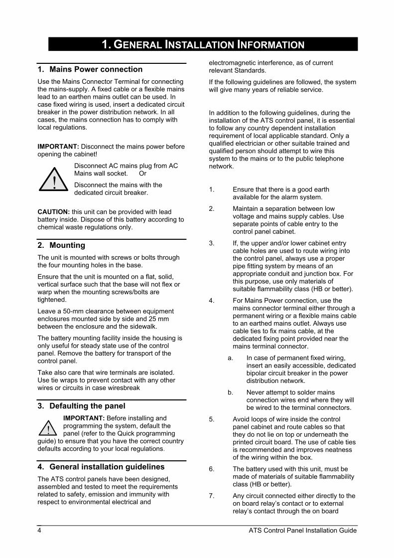
1. Mains Power connection Use the Mains Connector Terminal for connecting the mains-supply. A fixed cable or a flexible mains lead to an earthen mains outlet can be used. In case fixed wiring is used, insert a dedicated circuit breaker in the power distribution network. In all cases, the mains connection has to comply with local regulations.
IMPORTANT: Disconnect the mains power before opening the cabinet!
Disconnect AC mains plug from AC Mains wall socket. Or
Disconnect the mains with the dedicated circuit breaker.
CAUTION: this unit can be provided with lead battery inside. Dispose of this battery according to chemical waste regulations only.
2. Mounting The unit is mounted with screws or bolts through the four mounting holes in the base.
Ensure that the unit is mounted on a flat, solid, vertical surface such that the base will not flex or warp when the mounting screws/bolts are tightened.
Leave a 50-mm clearance between equipment enclosures mounted side by side and 25 mm between the enclosure and the sidewalk.
The battery mounting facility inside the housing is only useful for steady state use of the control panel. Remove the battery for transport of the control panel.
Take also care that wire terminals are isolated. Use tie wraps to prevent contact with any other wires or circuits in case wiresbreak
3. Defaulting the panel IMPORTANT: Before installing and programming the system, default the panel (refer to the Quick programming
guide) to ensure that you have the correct country defaults according to your local regulations.
4. General installation guidelines The ATS control panels have been designed, assembled and tested to meet the requirements related to safety, emission and immunity with respect to environmental electrical and
electromagnetic interference, as of current relevant Standards.
If the following guidelines are followed, the system will give many years of reliable service.
In addition to the following guidelines, during the installation of the ATS control panel, it is essential to follow any country dependent installation requirement of local applicable standard. Only a qualified electrician or other suitable trained and qualified person should attempt to wire this system to the mains or to the public telephone network.
1. Ensure that there is a good earth available for the alarm system.
2. Maintain a separation between low voltage and mains supply cables. Use separate points of cable entry to the control panel cabinet.
3. If, the upper and/or lower cabinet entry cable holes are used to route wiring into the control panel, always use a proper pipe fitting system by means of an appropriate conduit and junction box. For this purpose, use only materials of suitable flammability class (HB or better).
4. For Mains Power connection, use the mains connector terminal either through a permanent wiring or a flexible mains cable to an earthed mains outlet. Always use cable ties to fix mains cable, at the dedicated fixing point provided near the mains terminal connector.
a. In case of permanent fixed wiring, insert an easily accessible, dedicated bipolar circuit breaker in the power distribution network.
b. Never attempt to solder mains connection wires end where they will be wired to the terminal connectors.
5. Avoid loops of wire inside the control panel cabinet and route cables so that they do not lie on top or underneath the printed circuit board. The use of cable ties is recommended and improves neatness of the wiring within the box.
6. The battery used with this unit, must be made of materials of suitable flammability class (HB or better).
7. Any circuit connected either directly to the on board relay’s contact or to external relay’s contact through the on board

ATS Control Panel Installation Guide 5
electronic output, must be of SELV (Safety extra-low voltage) operating circuit.
a. Mains switching relay must not be fitted inside the control panel cabinet
b. Always place a suppression diode (e.g. a 1N4001) across the relay coil
c. Use only relay with good insulation between the contacts and the coil.
8. The minimum clearance between equipment closures is 50 mm (between equipment vents).
9. Only use units in a clean environment and not in humid air.

ATS Control Panel Installation Guide 6
5. Installation ATS 2000/3000 variants
(1) Earth connection. Use also for cable screen and lid of box.
(2) Eprom (Factory fitted) (3) RAM or IUM (ATS2400/2600/3000 variants
only) (4) TST1 restore master user code (5) TST 2 factory use only (6) Ferrite for PSTN. Requires 1 loop each for
incoming and outgoing cables. Feed the cable through the nearest hole out of the box.
J5-J6 Zones J7 Interface to ATS1202 input expanders J8 Clock-out Interface to plug on output
expansion or 4-way non-clocked.
J9 On board relay output.
J10 RS485 system databus and box tamper connections
J11 Connector to printer or printer/PC board (ATS1801)(ATS3000 only)
J13 Siren and strobe connections J14 Auxiliary power output (SW+ & SW-
ATS2400/2600/3000 variants only) J16 PSTN line connection J17 Power connections J18 Serial connection (RS232) J20 Connector to ISDN/Audio J2, J3, J4, J15, J19 - Not fitted To conform with CEI 79-2 regulations at level 2, the use of the pry-off tamper is mandatory (ST580 kit) For detailed information on the PCB, see connection diagram on page 7.

ATS
Con
trol P
anel
Inst
alla
tion
Gui
de
7
Con
nect
ion
diag
ram
(ATS
2000
/300
0 va
riant
s)
(1)
Ferri
te (r
equi
red)
. Bot
h in
com
ing
and
outg
oing
PST
N w
ires
requ
ire 1
lo
op.
(2)
AC c
onne
ctio
n fro
m tr
ansf
orm
er
(3)
Syst
em e
arth
(see
det
ails
pag
e 12
) (4
) 12
V b
atte
ry
(5)
Switc
habl
e au
xilia
ry o
utpu
t (AT
S240
0/26
00/3
000
varia
nts
only
) (6
) Ex
tern
al 8
Ohm
sire
n sp
eake
r or s
iren
(7)
1K re
sist
or m
ust b
e fit
ted
if ex
tern
al s
iren
not c
onne
cted
(8
) In
tern
al 8
Ohm
sire
n sp
eake
r (9
) 12
V s
trobe
(1
0)
Syst
em d
atab
us
(11)
N
orm
ally
clo
sed
front
pan
el ta
mpe
r con
tact
(1
2)
Nor
mal
ly c
lose
d re
ar p
anel
tam
per c
onta
ct
(13)
N
orm
ally
Clo
sed
Alar
m C
onta
ct
(14)
N
orm
ally
Clo
sed
Tam
per c
onta
ct
(15)
AT
S181
0/11
/20
pow
er s
elec
tion
(16)
R
AM o
r IU
M (A
TS24
00/2
600/
3000
var
iant
s on
ly, o
ptio
nal)
(17)
EP
RO
M (f
acto
ry fi
tted)
(1
8)
Kill
- Fac
tory
def
ault
cont
rol p
anel
whe
n sh
orte
d
(19)
Zo
ne 9
-16
jum
per.
Shor
t whe
n AT
S120
2 is
con
nect
ed to
J7.
(2
0)
Test
2 –
Fac
tory
use
onl
y
(21)
Te
st 1
– U
se fo
r res
ettin
g th
e M
aste
r Eng
inee
r cod
e
(22)
IS
P C
ircui
t pro
gram
min
g co
nnec
tor u
sed
to p
rogr
am th
e C
PL. (
fact
ory
used
) J5
-J6
Zone
s J7
In
terfa
ce to
ATS
1202
inpu
t exp
ande
rs. S
hort
9-16
jum
per w
hen
usin
g zo
ne 9
-16.
J8
C
lock
-out
Inte
rface
to p
lug
on o
utpu
t exp
ansi
on o
r 4-w
ay n
on-
cloc
ked.
J9
O
n bo
ard
rela
y ou
tput
. J1
0 R
S485
sys
tem
dat
abus
and
box
tam
per c
onne
ctio
ns
J11
Con
nect
or to
prin
ter o
r prin
ter/P
C b
oard
(ATS
1801
) (AT
S300
0 va
riant
s on
ly)
J13
Sire
n an
d st
robe
con
nect
ions
J1
4 Au
xilia
ry p
ower
out
put (
SW+
& SW
- A
TS24
00/2
600/
3000
var
iant
s on
ly)
J16
PSTN
line
con
nect
ion
J1
7 Po
wer
con
nect
ions
J1
8 Se
rial c
onne
ctio
n (R
S232
) J2
0 C
onne
ctor
to IS
DN
/Aud
io
J2, J
3, J
4, J
15, J
19
Not
fitte
d
Tem
pora
ry s
ervi
ce c
onne
ctio
n –
seria
l por
t (J1
8)
Use
the
ATS1
630
prog
ram
min
g ca
ble.
ATS Control Panel Installation Guide 8
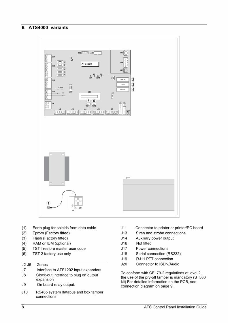
6. ATS4000 variants
(1) Earth plug for shields from data cable. (2) Eprom (Factory fitted) (3) Flash (Factory fitted) (4) RAM or IUM (optional) (5) TST1 restore master user code (6) TST 2 factory use only J2-J6 Zones J7 Interface to ATS1202 input expanders J8 Clock-out Interface to plug on output
expansion J9 On board relay output.
J10 RS485 system databus and box tamper connections
J11 Connector to printer or printer/PC board J13 Siren and strobe connections J14 Auxiliary power output J16 Not fitted J17 Power connections J18 Serial connection (RS232) J19 RJ11 PTT connection J20 Connector to ISDN/Audio To conform with CEI 79-2 regulations at level 2, the use of the pry-off tamper is mandatory (ST580 kit) For detailed information on the PCB, see connection diagram on page 9.

ATS
Con
trol P
anel
Inst
alla
tion
Gui
de
9
Con
nect
ion
diag
ram
(ATS
4000
var
iant
s)
(1)
Ferri
te (r
equi
red)
. Bot
h in
com
ing
and
outg
oing
PST
N w
ires
requ
ire 1
loop
. (2
) AC
con
nect
ion
from
tran
sfor
mer
(3
) Sy
stem
ear
th (s
ee d
etai
ls p
age
12)
(4)
12 V
bat
tery
(5
) Sw
itcha
ble
auxi
liary
out
put
(6)
Exte
rnal
8 O
hm s
iren
spea
ker o
r sire
n (7
) 1K
resi
stor
mus
t be
fitte
d if
exte
rnal
sire
n no
t con
nect
ed
(8)
Inte
rnal
8 O
hm s
iren
spea
ker
(9)
12 V
stro
be
(10)
Sys
tem
dat
abus
(1
1) N
orm
ally
clo
sed
front
pan
el ta
mpe
r con
tact
(1
2) N
orm
ally
clo
sed
rear
pan
el ta
mpe
r con
tact
(1
3) N
orm
ally
Clo
sed
Alar
m C
onta
ct
(14)
Nor
mal
ly C
lose
d Ta
mpe
r con
tact
(1
5) A
TS18
10/1
1/20
pow
er s
elec
tion
(16)
RAM
or I
UM
(opt
iona
l) (1
7) E
PRO
M (f
acto
ry fi
tted)
(1
8) K
ill - F
acto
ry d
efau
lt co
ntro
l pan
el w
hen
shor
ted
(19)
Fla
sh
(20)
Tes
t 2 –
Fac
tory
use
onl
y (2
1) T
est 1
– U
se fo
r res
ettin
g th
e M
aste
r Eng
inee
r cod
e (2
2) IS
P C
ircui
t pro
gram
min
g co
nnec
tor,
us
ed to
pro
gram
the
CPL
D (f
acto
ry u
sed)
J2
- J6
Zo
ne w
iring
J7
ATS1
202
Zone
exp
ansi
on
J8
C
LKO
UT
(ATS
1810
/182
0)
J9
Pr
ogra
mm
able
rela
y ou
tput
J1
0
Com
ms
and
pane
l tam
per w
iring
J1
1
Com
pute
r/prin
ter e
xpan
sion
(ATS
1801
) J1
3
Sire
ns/S
trobe
Con
nect
ion
J14
Au
xilia
ry p
ower
J1
5
RJ4
5 PT
T co
nnec
tor (
not f
itted
) J1
6
PSTN
Lin
e co
nnec
tion
J17
Po
wer
J1
8
Seria
l con
nect
ion
(RS2
32)
J19
R
J45
PTT
conn
ecto
r J2
0
ISD
N/A
udio
Inte
rface
Earth Lug J17 - Power System earth
(see details page 4)12 V battery. J14 - Auxiliar
y powerJ13 Sirens/S
trobe ConnectionExternal 8 Oh
m siren speaker or sirene
1K resistor must be fitted if external si
ren not connected.Internal 8 Oh
m siren speaker 12 V strobeJ3 - Comms
and panel tamper wiring
System databus
Normally closed front panel tamper co
ntactNormally clos
ed rear panel tamper contact
J9 - BellJ2 to J6 Zone wiring
Normally Closed Alarm Contact
Normally Closed Tamper contact
J7 ATS1202 Zone expansion
J8 - CLKOUT (ATS1810/1820)
+12V Output board
J11 Computer/printer expansion
J18 Serial connection (RS232)
J20 ISDN/Audio Interface
J15/J19 RJ45 PTT connector (not fitte
d)J16 PSTN L
ine connection
EPROM (factory fitted)
Flash/RAM or IUM (optional)
ISP. Circuit programming connector, u
sed to program the CPLD (factory used)
Test 1 Use for resetting the Master E
ngineer code.Test 2 Facto
ry use onlyTo be used fo
r ATS1202 (only with ATS3000)
J6 1 C 2 C 3 CS+ S-S+S-+ -1211J10
TH1 TH3TH5T H2TH4
NE GCPOS
J5 4 C 5 C 6 CJ4 7 C 8 C 9 CJ3 10 C 11 C 12 CJ2 13 C 14 C 15 C16 C
J11
J7RAM/IUMFL ASHEPROMABAXBXEA J15J19 J16J18J20 TST1TST2
+12V
9-16ISP
KILL
12V RX TX 0V
1413
15J930
16161616
16
171718
19
2324
2526 2728
29
313233
34
25 28
J17 J14 J13
J8
Temporary service connection - serial Port (J1PC Connec
ATS3000/4000J18DB25Db9
12VRX.............................TX23
TX.............................RX32
0V..............................GND75
1011 121314 151617 181920 212223 242526 272829 303132 33342 345 671 8 9
22
Kill - Factory default control panel when shorted
Transformer AC connection
E arth Lug J17 - Power System earth (see details page 4)
12 V battery. J14 - Auxiliary power
J13 Sirens/Strobe Connection
External 8 Ohm siren speaker or siren
e
1K resistor must be fitted if external si
ren not connected.Internal 8 Oh
m siren speaker 12 V strobeJ3 - Comms
and panel tamper wiring
System databus
Normally closed front panel tamper co
ntactNormally clos
ed rear panel tamper contact
J9 - BellJ2 to J6 Zone wiring
Normally Closed Alarm Contact
Normally Closed Tamper contact
J7 ATS1202 Zone expansion
J8 - CLKOUT (ATS1810/1820)
+12V Output board
J11 Computer/printer expansion
J18 Serial connection (RS232)
J20 ISDN/Audio Interface
J15/J19 RJ45 PTT connector (not fitte
d)J16 PSTN L
ine connection
EPROM (factory fitted)
Flash/RAM or IUM (optional)
ISP. Circuit programming connector, u
sed to program the CPLD (factory used)
Test 1 Use for resetting the Master E
ngineer code.Test 2 Facto
ry use onlyTo be used fo
r ATS1202 (only with ATS3000)
J6 1 C 2 C 3 CS+ S-S+S-+ -1211J10
TH1 TH3TH5T H2TH4
NE GCPOS
J5 4 C 5 C 6 CJ4 7 C 8 C 9 CJ3 10 C 11 C 12 CJ2 13 C 14 C 15 C16 C
J11
J7RAM/IUMFL ASHEPROMABAXBXEA J15J19 J16J18J20 TST1TST2
+12V
9-16ISP
KILL
12V RX TX 0V
1413
15J930
16161616
16
171718
19
2324
2526 2728
29
313233
34
25 28
J17 J14 J13
J8
Temporary service connection - serial Port (J1PC Connec
ATS3000/4000J18DB25Db9
12VRX.............................TX23
TX.............................RX32
0V..............................GND75
1011 121314 151617 181920 212223 242526 272829 303132 33342 345 671 8 9
22
Kill - Factory default control panel when shorted
Transformer AC connection
Tem
pora
ry s
ervi
ce c
onne
ctio
n –
seria
l por
t (J1
8)
Use
the
ATS1
630
prog
ram
min
g ca
ble.

ATS Control Panel Installation Guide 10
7. Cabling (ATS2000/3000 variants) System databus connection diagram preferred wiring. The “TERM” link is on the first and last devices on the system databus. In a “star” wiring configuration, the “TERM” link is only fitted on the devices at the ends of the two longest system databus cable runs.
TERM link fitted (first device on local databus)
Control Panel ATS2000/3000 variants
ATS1105 LCD RAS (TERM switch not set to ON)
Separate 12 V power supply. (Required if RAS is more than 100 m from the nearest panel or DGP. Connect “-“ to “-“ of the databus.)
Preferred data cable type is WCAT 52 (2 pair twisted).
TERM link fitted (last device on local databus)
Earth connection to connect shield*
Any data gathering panel like ATS1201, ATS1210, ATS1220 or ATS1250.
*Connect cable shield to one device only.
See: System databus connection and Earthing details on page 12 LEDs
L1: Flashes slowly when the panel is operating (the microprocessor is running)
COMMS
Rx: Yellow LED flashes when remote units (RAS and DGP) are replying to polling.
Tx: Red LED flashes when panel is polling remote unit(s). It must always be active.
MODEM
Rx1: Yellow LED flashes when data is being received from a device connected to the PTT line (J15/J16/J19) (central station or dialler modem) or J18 (serial port (RS232 PC).
Tx1: Red LED flashes when data is being sent from the panel to a device connected to the PTT line (J15/J16) or J18 serial port..

ATS Control Panel Installation Guide 11
8. Cabling (ATS4000 variants) System databus connection diagram preferred wiring.
The “TERM” link is on the first and last devices on the system databus. In a “star” wiring configuration, the “TERM” link is only fitted on the devices at the ends of the two longest system databus cable runs.
TERM link fitted (first device on local databus)
Control Panel ATS4000 variants
ATS1100/1105 LCD RAS (TERM switch not set to ON)TERM link not fitted
Separate 12 V power supply. Required if RAS is more than 100 m from the nearest panel or DGP. Connect “-“ to “-“ of the databus.
Preferred data cable type is WCAT 52 (2 pair twisted).
TERM link fitted (last device on local databus) TERM link fitted (last device on local databus).
Earth connection to connect shield*
Any data gathering panel like ATS1201, ATS1210, ATS1220 or ATS1250.
* Connect cable shield to one device only
See: System databus connection and Earthing details on page (10)
LEDs
L1: Flashes slowly when the panel is operating (the microprocessor is running)
COMMS
Rx: Yellow LED flashes when remote units (RAS and DGP) are replying to polling.
Tx: Red LED flashes when panel is polling remote unit(s). It must always be active.
MODEM
Rx1: Yellow LED flashes when data is being received from a device connected to the PTT line (J15/J16/J19) (central station or dialler modem) or J18 (serial port (RS232 PC).
Tx1: Red LED flashes when data is being sent from the panel to a device connected to the PTT line (J15/J16) or J18 serial port

ATS Control Panel Installation Guide 12
1. Mains power with local earth
2. Mains power connector
3. System databus
4. Earth lug
5. Building 1
6. Building 2
7. Device in metal housing
8. Device in plastic housing
9. ATS control panel
!
9. System databus connection The system databus is used to connect Data Gathering Panels (to provide extra zones) and Arming Stations to the ATS control panel. Remote devices can be up to 1.5 km from an ATS control panels.
Arming stations and Data Gathering Panels must be connected via a 2 pair twisted shielded data cable from the system databus connection. (WCAT 52 is recommended)
The shield of the data cable should be connected to earth at the ATS control panel and should be left disconnected at any other end.
It is recommended that where the distance between the arming station and the nearest device is more than 100 meters, a separate power supply must be used to power the arming station.
To power the arming station, do not connect ‘+’ from the system databus. Connect '+' of the local power supply to '+' on the arming station and connect 0 volts from the power supply and 0 volts from the system databus to the arming station terminal marked ‘-’.
See Cabling on page 10 and 11.
10. Mains connection Make sure that before connecting the mains power, the mains power supply is disconnected (see page 4).
When installing the mains power, use strain
relieves like cable ties and coupling PG16’s to ensure proper wiring. In all cases, local regulations should be applied.
11. Earthing WARNING! Correct Earthing procedures
must be followed. Earthing of one cabinet containing several
devices. All devices designed for the system have earth connections via metal studs to the metal housing. Take care, that these metal studs make good connection to the housing (beware of paint). The earth connections of every piece of equipment in the system, can be used for connecting the shielding of shielded cables. If a device is placed in a plastic housing the earth lug of this device does not have to be connected. Earthing panels in a single building. In one building several cabinets or devices are earthen to safety ground. The safety earth of this building has to be checked by a licensed contractor. Earthing panels in more buildings. If the wiring extends to separated buildings, more than one common earth system will be used. Use isolator/repeaters ATS1740 to isolate the system databus. In this way the system is protected against variations in earth potential.
Shielding The shielding of all shielded cables used in the system, should only be connected at ONE side to one common earthing point in a building (see figure) If a shielded databus cable is routed via more than one plastic device the shielding from incoming and out-going cable has to be connected.

ATS Control Panel Installation Guide 13
12. Mounting the hardware – Addressing
All data gathering panels (DGP’s), zones and outputs are numbered according to a set formula. This is used when determining the physical numbers/locations of DGP’s, outputs etc. when programming. Table 1: zones and outputs allocated to each DGP
Control panel 1-16 DGP 8 129-144
DGP 1 17-32 DGP 9 145-160 DGP 2 33-48 DGP 10 161-176
DGP 3 49-64 DGP 11 177-192
DGP 4 65-80 DGP 12 193-208
DGP 5 81-96 DGP 13 209-224
DGP 6 97-112 DGP 14 225-240 DGP 7 113-128 DGP 15 241-256
Zone configuration ATS control panels
Up to 8 zones can be connected to the ATS2000/3000 control panel, which are numbered from 1 to 8. Up to 16 zones can be connected to the ATS4000 control panel, which are numbered from 1 to 16. DGP 1 through 15 have zone numbers as shown in table 1. The ATS2000/3000 control panel can be expanded to a maximum of 24 zones using ATS1202. The ATS4000 control panel can be expanded to a maximum of 32 zones using ATS1202.
The ATS2000 and ATS3000 variants will allow only for 32 (ATS2000) or 64 zones (ATS3000) to be programmed with a zone type other than 0.
The ATS4000 variants will allow for the full extension of 255 zones other than type 0.
A standard DGP can have eight zones connected to it. Some of them can be expanded in increments of 8, up to 32, so a DGP can have 8, 16, 24 or 32 zones.
Expanding the number of zones connected to the control panel or a DGP to more than 16 using ATS 1202 is the same as combining two DGP addresses. The additional zones are taken from the next DGP. Do not include the next DGP for polling. This way of operation is used to maintain consistent numbering.
e.g. DGP1 has 32 zones (DGP2 consequently cannot exist as DGP1 has used the zones allocated to its address. DGP2 should not be used)
DGP3 is therefore the second physical unit. If it has 24 or 32 zones, DGP4 cannot exist and so on.
ATS1250 and ATS1260 are also DGP’s, and their zones follow the standard zone numbering.
e.g. ATS1250 1 is DGP1 and has 16 zones, which the ATS control panel identifies as zones 17 to 32.
8-32 zone DGP programming (ATS1201, ATS1210, ATS1211, ATS1220, ATS1221, ATS1250) For each DGP programmed to be polled, the ATS control panel expects to see 16 or 32 zones, depending on the setting of Dipswitch 5.
If a DGP is connected with only 8 or 24 zones, the unused zone numbers in the system must be programmed in the Zone Database as type 0 (Zone disabled). The same applies to the control panel if only more then 8 zones are connected.
e.g. DGP 1 has 24 zones (2 zone expanders fitted & Dipswitch 5 on). Therefore, zones 41 to 48 must be programmed as Type 0.
Outputs Output controllers are used to expand the number of outputs on a DGP or control panel. Each output controller expands the outputs by eight.
A DGP can have two output controllers connected, increasing the outputs to a maximum of 16 per DGP.
An ATS control panel can have up to 32 output controllers, which allows a maximum of 255 outputs.
If there are more than 16 outputs connected to the main ATS control panel, the outputs from output number 17 are duplicated on the DGP. When this is done, one of two options can be used: - Do not use the outputs on the DGP, or - both outputs are activated together.
e.g. The ATS control panel has 24 outputs available and DGP 1 has 8 outputs available. When output 17 is active, the first output on the third ATS1811 output controller connected to the ATS panel; and the first output on DGP 1 are both activated.
Output and zone numbers are always the same as the first 16 zone numbers on the DGP they are connected to. If a DGP does not exist because the previous DGP has an expanded number of zones, the output numbers of that DGP address cannot be used.
The output numbers can be used if output controllers are connected to the ATS panel that corresponds to those output numbers.
e.g. DGP1 has 32 zones: 17-48 DGP1 outputs (max 16): 17-32 (DGP2 outputs 33-48 are not used) DGP3 has 32 zones: 49-80 DGP3 outputs: 49-64 (DGP4 outputs 65-80 are not used)

ATS Control Panel Installation Guide 14
Outputs on a DGP only exist if the DGP exists.
Siren outputs The internal and external siren speaker outputs on the ATS control panel, are always treated as output 16.
On DGP’s with siren speaker outputs, the last of the 16 output numbers associated with that DGP address is the siren output. For example, on DGP3 the siren speaker output is output 64 (See table 4). Table 4: Siren output numbers
DGP no.
Siren output no.
DGP no.
Siren output no.
1
2
3
4
5
6
7
8
32
48
64
80
96
112
128
144
9
10
11
12
13
14
15
160
176
192
208
224
240
-
To enable the siren speaker output, the output number representing the siren output must be assigned to the required "Siren Event Flag Number". The "Siren Event Flag Numbers" are programmed in programming menu 2 – Area Databases.
Output control groups Output control group numbers are a way of identifying a group of eight outputs controlled by the control panel, a DGP or an arming station.
When an output control group is assigned to an arming station, the Open Collector output (or "OUT") terminal follows the FIRST output of the output control group.
For further information refer to programming menu 3 - Arming Stations.
Door and lift numbering Door numbers are determined by the address of the arming station or reader connected to the ATS system databus or 4-Door DGP local databus, and the 4-Door DGP address if applicable.
Doors 1 to 16 are reserved for arming stations 1 to 16 that are connected to the ATS system databus and used for door control functions.
Doors 17 to 64 are used for door or lift numbers that are controlled by a 4-Door/4-Lift DGP (ATS1250 or ATS1260). (See table 5). Table 5: Door/Lift numbers allocated to each DGP
Unit Door number RAS 1 to 16 1 to 16 (Door only)
Door or Lift 1st 2nd 3rd 4th DGP1 17 18 19 20 DGP2 21 22 23 24 DGP3 25 26 27 28 DGP4 29 30 31 32 DGP5 33 34 35 36 DGP6 37 38 39 40 DGP7 41 42 43 44 DGP8 45 46 47 48 DGP9 49 50 51 52
DGP10 53 54 55 56 DGP11 57 58 59 60 DGP12 61 62 63 64
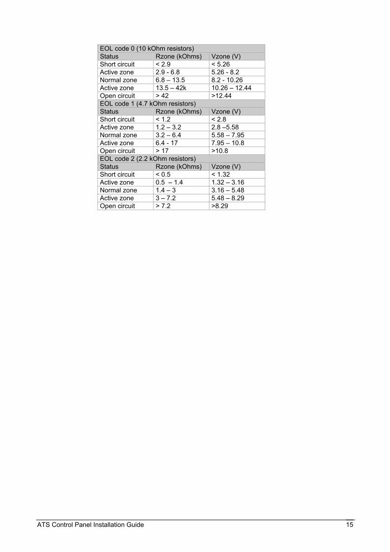
Values for end-of-line resistors. The following list contains the values to be used for end-of-line resistors. Both the resistance and the voltage over the zone are shown. The voltage will differ for other power supply voltages measured. To get the current power supply voltage measure the voltage over the zone when it is open. The end of line resistor used is based on the setting for the end of line resistor code as programmed in the system options (see ATS control panel programming guide).
ATS Control Panel Installation Guide 15
EOL code 0 (10 kOhm resistors) Status Rzone (kOhms) Vzone (V) Short circuit < 2.9 < 5.26 Active zone 2.9 - 6.8 5.26 - 8.2 Normal zone 6.8 – 13.5 8.2 - 10.26 Active zone 13.5 – 42k 10.26 – 12.44 Open circuit > 42 >12.44 EOL code 1 (4.7 kOhm resistors) Status Rzone (kOhms) Vzone (V) Short circuit < 1.2 < 2.8 Active zone 1.2 – 3.2 2.8 –5.58 Normal zone 3.2 – 6.4 5.58 – 7.95 Active zone 6.4 - 17 7.95 – 10.8 Open circuit > 17 >10.8 EOL code 2 (2.2 kOhm resistors) Status Rzone (kOhms) Vzone (V) Short circuit < 0.5 < 1.32 Active zone 0.5 – 1.4 1.32 – 3.16 Normal zone 1.4 – 3 3.16 – 5.48 Active zone 3 – 7.2 5.48 – 8.29 Open circuit > 7.2 >8.29

ATS Control Panel Installation Guide 16
2. TECHNICAL SPECIFICATIONS 1. Mains Power Specifications
Mains Input Voltage 230 VAC ± 10% - 50Hz ± 10% - 58 VA
Current consumption at 230V~ 250 mA max.
Main board supply voltage (AC:J17) 23 VAC typical 2. Power Supply Specifications
Power supply voltage 13.8 VDC ± 0.2 V
14.4 VDC ± 0.2 V at SW+ (ATSx100/x400/x600)
Power supply current 2.0 A max. at 13.8 VDC ± 0.2 V (ATSx000/x200/x500) 3.0 A max. at 13.8 VDC ± 0.2 V (ATSx100/x400/x600)
Auxiliary Power output (AUX. POWER: J14)
13.8 VDC ± 0.2 V 500 mA max. (ATSx000/x200/x500) 13.8 VDC ± 0.2 V 680 mA max. (ATS2100/3100/2400/3400/2600/3600) 13.8 VDC ± 0.2 V 600 mA max. (ATS4600) Note: maximum permanent current to power devices external to the control equipment in the absence of alarm conditions.
Battery Power output (BAT:J17) 13.8 VDC ± 0.2 V 1300 mA max. (ATSx000/x200/x500) 13.8 VDC ± 0.2 V 2200 mA max. (ATSx100/x400/x600)
Battery Type lead acid rechargeable 18 Ah 12 V nom. (BS131)1
Main board consumption 200 mA at 13.8 VDC ± 0.2 V 120 mA at 13.8 VDC ± 0.2 V (ATS2100/3100/2400/3400/2600/3600 only)
3. General Feature Specifications
Nr. of combination of codes From 10,000 (4 digits) to 1 Billions (9 digits)
End of line resistor 4.7 KOhm, 5% 0.25 W (Standard), 10 KOhm, 2.2 KOhm
Programmable relay (J9) NC/NO Relay Rating: 2 A at 13.8 VDC
Ext.siren & Strobe (EXT STRB: J13)
Electronic output Rating: 1 A at 13.8 VDC
Standard On board Output Note: see general installation guidelines
Internal siren (INT J13) Electronic output Rating: 1 A at 13.8 VDC
Programmable output by event flag 251 * not available in the ATS2000/2200/2500
Switched Output (SW+/SW: J14)-
Electronic output Rating: 1 A at 13.8 VDC
Housing Panel Dimensions Colour Beige ATS1646 ATS2000/3000/2100/3100 315x388x85 mm ATS1640 ATS4000 315x445x88 mm ATS1646 ATSx200/x400 475x370x160 mm ATS1642 ATSx500/x600 475x460x160 mm
Operating temperature 0° to + 50 °C
Humidity 95% non condensing
Environmental
IP protection grade IP30 4. Fuses
F1 Ext. siren + strobe 1 A, fast 20x5 F4 12V aux. - (ATS3000/3200/3500 also SW+/SW)
2 A, fast 20x5
F2 ATS2000/3000/2200/3200/2500/3500
Not used F5 Battery 3.15 A, fast 20x5
ATS Control Panel Installation Guide 17
ATSx100/x400/x600/4000 Switched aux. Output (SW+/SW-)
1A, fast 20x5
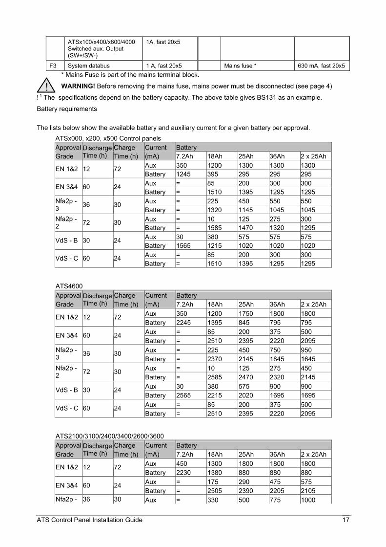
F3 System databus 1 A, fast 20x5 Mains fuse * 630 mA, fast 20x5 * Mains Fuse is part of the mains terminal block.
WARNING! Before removing the mains fuse, mains power must be disconnected (see page 4)
! 1 The specifications depend on the battery capacity. The above table gives BS131 as an example.
Battery requirements
The lists below show the available battery and auxiliary current for a given battery per approval.
ATSx000, x200, x500 Control panels Approval Charge Current Battery Grade
Discharge Time (h) Time (h) (mA) 7.2Ah 18Ah 25Ah 36Ah 2 x 25Ah
Aux 350 1200 1300 1300 1300 EN 1&2 12 72 Battery 1245 395 295 295 295 Aux = 85 200 300 300 EN 3&4 60 24 Battery = 1510 1395 1295 1295 Aux = 225 450 550 550 Nfa2p -
3 36 30 Battery = 1320 1145 1045 1045 Aux = 10 125 275 300 Nfa2p -
2 72 30 Battery = 1585 1470 1320 1295 Aux 30 380 575 575 575 VdS - B 30 24 Battery 1565 1215 1020 1020 1020 Aux = 85 200 300 300 VdS - C 60 24 Battery = 1510 1395 1295 1295
ATS4600 Approval Charge Current Battery Grade
Discharge Time (h) Time (h) (mA) 7.2Ah 18Ah 25Ah 36Ah 2 x 25Ah
Aux 350 1200 1750 1800 1800 EN 1&2 12 72 Battery 2245 1395 845 795 795 Aux = 85 200 375 500 EN 3&4 60 24 Battery = 2510 2395 2220 2095 Aux = 225 450 750 950 Nfa2p -
3 36 30 Battery = 2370 2145 1845 1645 Aux = 10 125 275 450 Nfa2p -
2 72 30 Battery = 2585 2470 2320 2145 Aux 30 380 575 900 900 VdS - B 30 24 Battery 2565 2215 2020 1695 1695 Aux = 85 200 375 500 VdS - C 60 24 Battery = 2510 2395 2220 2095
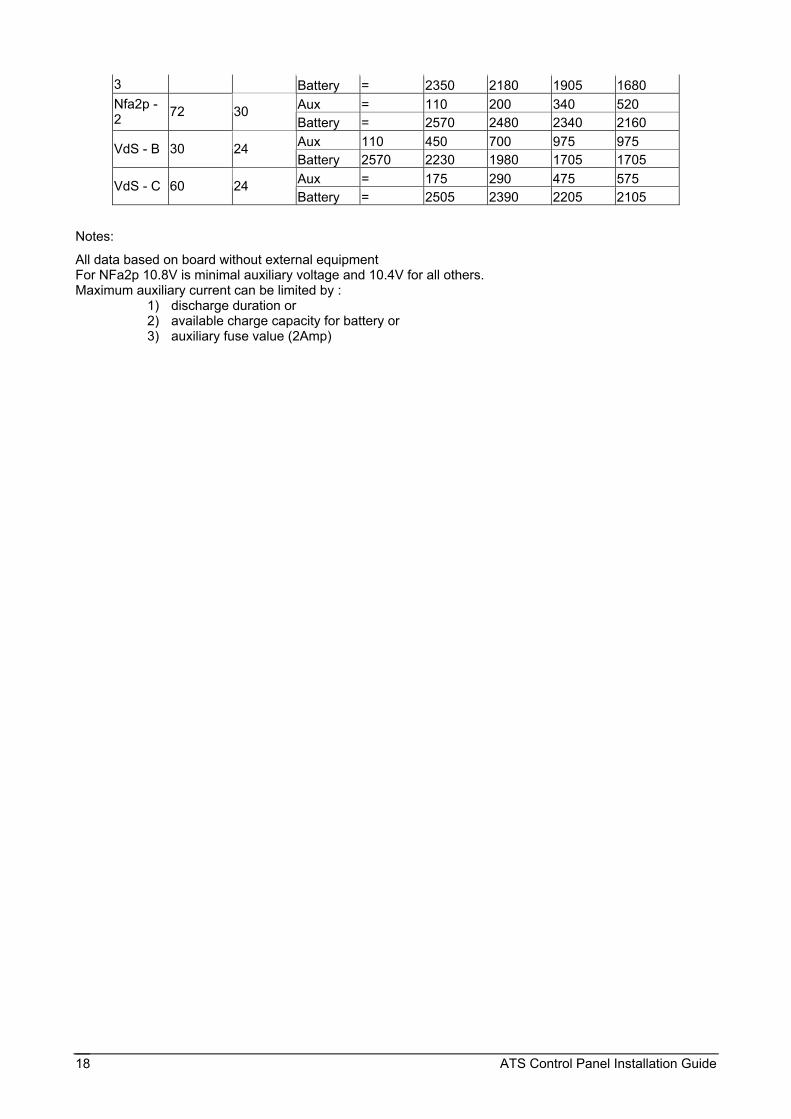
ATS2100/3100/2400/3400/2600/3600 Approval Charge Current Battery Grade
Discharge Time (h) Time (h) (mA) 7.2Ah 18Ah 25Ah 36Ah 2 x 25Ah
Aux 450 1300 1800 1800 1800 EN 1&2 12 72 Battery 2230 1380 880 880 880 Aux = 175 290 475 575 EN 3&4 60 24 Battery = 2505 2390 2205 2105
Nfa2p - 36 30 Aux = 330 500 775 1000
!
ATS Control Panel Installation Guide 18
3 Battery = 2350 2180 1905 1680 Aux = 110 200 340 520 Nfa2p -
2 72 30 Battery = 2570 2480 2340 2160 Aux 110 450 700 975 975 VdS - B 30 24 Battery 2570 2230 1980 1705 1705 Aux = 175 290 475 575 VdS - C 60 24 Battery = 2505 2390 2205 2105
Notes:
All data based on board without external equipment For NFa2p 10.8V is minimal auxiliary voltage and 10.4V for all others. Maximum auxiliary current can be limited by :
1) discharge duration or 2) available charge capacity for battery or 3) auxiliary fuse value (2Amp)

ATS Control Panel Installation Guide 19
SECURITY LIFESAFETY COMMUNICATIONS
MANUFACTURERS DECLARATION OF CONFORMITY
For
Product identification: Model/type : ATS2000/ATS3000
BOM revision level : See attached model listing
Category (description) : Intrusion Control Panel Brand : InterlogiX/Aritech / SLC Technologies / Sentrol/ESL/ITI/Caddx/Cqsi Rusco/Tecom Manufacturer:
GE Interlogix Greenhills Road Tallagt Dublin 24 Ireland
EU Representative: InterlogiX Europe & Africa.
Kelvinstraat 7 6003 DH Weert, The Netherlands
Concerning RTTE EMC Safety Telecom A sample of the product has been tested by:
Interlogix, Bicon Dare Dare/KTL
Test report reference CE qualification plan: 01.0075 Applied standards EN50130-4(1995) +A1(1998)
EN50081-1(1992) EN55022(1998) EN61000-3-2(1995) +A14, class A(2000) EN61000-3-3(1995)
EN60950(2000)
PSTN: CTR21(1998) +EG201121(1998)
Equipment class identifier (RF products falling under the scope of R&TTE)
X Not Applicable None (class 1 product) (class 2 product) Means of conformity We declare under our sole responsibility that this product is in conformity with Directive 93/68/EEC (Marking) and all other relevant provisions of the 1999/5/EC (R&TTE) based on test results using (non)harmonized standards in accordance with the Directives mentioned.
Date : 6 april 2004 Number: 01.134a
1048984
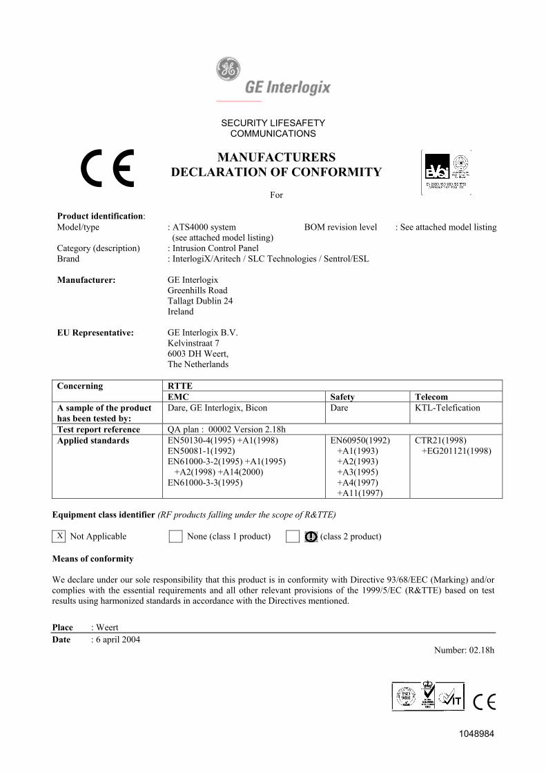
SECURITY LIFESAFETY COMMUNICATIONS
MANUFACTURERS DECLARATION OF CONFORMITY
For
Product identification: Model/type : ATS4000 system
(see attached model listing) BOM revision level : See attached model listing
Category (description) : Intrusion Control Panel Brand : InterlogiX/Aritech / SLC Technologies / Sentrol/ESL Manufacturer:
GE Interlogix Greenhills Road Tallagt Dublin 24 Ireland
EU Representative: GE Interlogix B.V.
Kelvinstraat 7 6003 DH Weert, The Netherlands
Concerning RTTE EMC Safety Telecom A sample of the product has been tested by:
Dare, GE Interlogix, Bicon Dare KTL-Telefication
Test report reference QA plan : 00002 Version 2.18h Applied standards EN50130-4(1995) +A1(1998)
EN50081-1(1992) EN61000-3-2(1995) +A1(1995) +A2(1998) +A14(2000) EN61000-3-3(1995)
EN60950(1992) +A1(1993) +A2(1993) +A3(1995) +A4(1997) +A11(1997)
CTR21(1998) +EG201121(1998)
Equipment class identifier (RF products falling under the scope of R&TTE)
X Not Applicable None (class 1 product) (class 2 product) Means of conformity We declare under our sole responsibility that this product is in conformity with Directive 93/68/EEC (Marking) and/or complies with the essential requirements and all other relevant provisions of the 1999/5/EC (R&TTE) based on test results using harmonized standards in accordance with the Directives mentioned.
Place : Weert Date : 6 april 2004
Number: 02.18h