at&t - 75--/system... · 5-11 5-16 5-20 5-22 iii. table of contents (contd) digital announcer...
TRANSCRIPT

AT&T
AT&T System 75and System 75 XE
Wiring

AT&T
AT&T System 75
and System 75 XE
Wiring
555-200-111Issue 2, August 1989

Call:
Write:
TO ORDER COPIES OF THIS MANUAL
AT&T Customer Information Center on 800-432-6600In Canada Call 800-255-1242
AT&T Customer Information Center2855 North Franklin RoadP.O. Box 19901Indianapolis, Indiana 46219-1385
TO COMMENT ON THIS MANUAL
Call: The AT&T Document Development Organization
Hot Line: 800-334-0404
In North Carolina Call 919-727-3167
While reasonable efforts were made to ensure that the information
in this document was complete and accurate at the time of printing,
AT&T can assume no responsibility for errors. Changes or
corrections to the information in this document may be incorporated
into future reissues.
Published byThe AT&T DocumentationManagement Organization
Copyright© 1989 AT&TAll Rights Reserved
Printed in U.S.A.

TABLE OF CONTENTSPage
CHAPTER 1. INTRODUCTIONGeneral
OrganizationUse of GuideEquipment
System Wiring
Cross-Connect Hardware SelectionWiring Hardware Changes
PlanningJob AidsVoice TerminalsSite or Satellite ClosetsCabling Facilities
CHAPTER 2. HARDWARE(66/110-Type)
General
110-Type Hardware Description110-Type Wiring BlocksIndex Strips and Connecting Blocks110A-Type Hardware110P-Type Hardware188-Type BackboardsCordsJumpersToolsF Clip Terminal InsulatorDesignation Strips
66-Type Hardware Description66M1-50 Connecting BlockConnectorized 66-Type Connecting BlocksMultiple-Mounted 66-Type Connecting Blocks183-Type Backboards187B1 BackboardPower Adapter CordsJumpersTools
1-1
1-1
1-41-51-5
1-5
1-91-10
1-111-111-111-131-13
2-1
2-1
2-32-32-42-7
2-112-182-182-212-212-222-22
2-232-232-242-252-262-282-282-292-30
i

TABLE OF CONTENTS (Contd)Page
Bridging Clips
Associated HardwareCable Slack ManagersNetwork InterfacesSneak Fuse PanelsEmergency Transfer UnitsTrunk Concentrator Cables
2-30
2-312-312-342-342-372-39
16-Port Analog Line Circuit Pack Adapter Cable (For 110-TypeHardware Only)4-Port Met Line Circuit Pack Concentrator Cable
Adjunct Power Units
2-452-46
2-47
CHAPTER 3. EQUIPMENT ROOMDESIGN
General
Hardware Equipment Room AppplicationsTrunk/Auxiliary FieldDistribution Field
Typical System Equipment Room Floor PlansGeneralTypical Floor PlansWall Space RequirementsEquipment Requirements
Equipment Room Hardware And Cabling InstallationHardware InstallationInstalling Cable Slack ManagersLabeling the Cross-Connect FieldInstalling Sneak Fuse PanelsCable Installation
Station Wiring DesignGeneralStation Circuit Distribution From Equipment RoomLayout
3-1
3-1
3-13-13-4
3-133-133-133-203-21
3-253-253-323-323-633-64
3-903-903-98
3-107
i i

TABLE OF CONTENTS (Contd)Page
CHAPTER 4. STATION WIRINGInstallation of Station Wiring And Associated Hardware
Installing Station CablesInstalling 110-Type Hardware at Satellite LocationsInstalling 66-Type Hardware at Satellite LocationsInstalling 4-Pair Station CablesInstalling Information Outlets
Adjunct PoweringAdjunct Powering From the Equipment Room and SatelliteLocationsAdjunct Powering From Site LocationsAdjunct Powering From Information Outlets
Patch Cord/Jumper Installation And AdministrationEquipment Room Cross-Connect FieldSatellite Locations
Miscellaneous Wiring InstallationInstalling System Access Terminal (SAT)Installing Attendant ConsoleInstalling Selector ConsoleInstalling lNADS lnterfaceInstalling DS1 Tie TrunksInstalling Customer-Provided Alarm—System 75 XE OnlyInstalling Off-Premises Station WiringInstalling Out-of-Building Station Wiring Installing Emergency Transfer Units and AssociatedTelephonesInstalling External RingingInstalling Queue Warning Indicator
CHAPTER 5. AUXILIARYEQUIPMENT INSTALLATION
Auxiliary Equipment DescriptionInstalling Loudspeaker Paging and Music-on-HoldInstalling Loudspeaker Paging Access—278A Paging AdapterInstalling Loudspeaker Paging Access—89A Control UnitInstalling PagePac® Paging SystemInstalling Music-on-Hold AccessInstalling Loudspeaker Paging With Background MusicInstalling Recorded Announcement Equipment
4-1
4-14-14-44-9
4-104-10
4-12
4-124-144-16
4-184-204-23
4-244-244-254-304-314-334-364-364-37
4-454-674-68
5-15-15-35-55-8
5-115-165-205-22
iii

TABLE OF CONTENTS (Contd)
Digital Announcer
Page
OnlyInstalling Audichron Wake-Up Announcement System—R1V3
Installing Dial Dictation EquipmentInstalling 3270 Data ModulesInstalling Processor Data Modules (PDMs)Installing AP Interface—System 75 OnlyInstalling AUDIX Interface—R1V3 OnlyInstalling CMS Interface—R1V3 OnlyInstalling DCS—R1V2 and R1V3 Installing PMS Interface—R1V3 OnlyInstalling Customer-Provided Terminal Using ADUsInstalling SMDR lnterfaceInstalling lSN lnterfaceInstalling STARLAN NETWORK InterfaceInstalling Premises Lightwave System (PLS) InterfaceInstalling Processor Interface/EIA Port
CHAPTER 6. GLOSSARY
CHAPTER 7. INDEX
5-26
5-285-325-335-365-395-425-425-435-445-455-455-495-525-535-55
6-1
7-1
iv
CHAPTER 1. INTRODUCTION
GeneraI
OrganizationUse of GuideEquipment
System Wiring
Cross-Connect Hardware SelectionWiring Hardware Changes
PlanningJob AidsVoice TerminalsSite or Satellite ClosetsCabling Facilities
1-1
1-41-51-5
1-5
1-91-10
1-111-111-111-131-13
-i-

Figures
Figure 1-1. Documentation Block Diagram 1-3Figure 1-2. System Uniform Wiring Plan 1-7Figure 1-3. Sample Uniform Wiring Installation 1-8Figure 1-4. Block Diagram of System 75 or 75 XE Installation 1-10Figure 1-5. Sample Floor Plan With Voice Terminal Locations
Marked 1-12Figure 1-6. Riser Cable Placement 1-14
-ii-

CHAPTER 1. INTRODUCTION
CHAPTER 1. INTRODUCTION
General
This guide is one of the three documents (Figure 1-1) required to installa System 75 or 75 XE switch. This guide describes the hardware, jobplanning, equipment ordering, and installation information from:
●
●
The telephone company network interface up to and including the25-pair cables that connect directly to the switch
The main equipment room cross-connect field and the associatedcabling from this cross-connect field to the switch cabinet and/or8-pin modular wall jacks (information outlets).
All information in this guide is compatible with both System 75 or 75 XE,except when a statement is made that a topic is strictly for a specificswitch.
The other documents required for the installation of the System 75 or 75XE are as follows:
AT&T System 75—Installation and Test (555-200-104):
Contains the information required to install and test a System 75switch and attendant console. For continuity purposes, theattendant console wiring is covered in this guide.
AT&T System 75— XE Installation and Test (555-201-104):
Contains the information required to install and test a System 75XE switch and attendant console. For continuity purposes, theattendant console wiring is covered in this guide.
DEFINITY™ Communications System and System 75, andSystem 85—Terminals and Adjuncts, Installation and Tests(555-015-104)
Contains the information required to instal l and testtelephones/voice terminals and their associated adjuncts.
1-1

CHAPTER 1. INTRODUCTION
This issue replaces all previous issues of this document. The reason forreissue is:
●
●
●
●
●
Remove information pertaining to Z100-type hardware.
Combine information for 66- and 110-type hardware.
Add processor/EIA interface connections.
Add digital out-of-building voice terminal connections.
Add connections for System Access Terminal (SAT).
1-2

General
MANUAL555-015-104
CENTRALOFFICETRUNKS
TERMINALSAND
ADJUNCTS
NETWORKINTERFACE
SNEAK FUSEPANEL
WIRING GUIDE(555-200-111)
MANUALSWITCH (555-200-104CABINET OR
AND 555-201-104)
CONSOLE
AUXILIARYEQUIPMENT
INFORMATIONOUTLET
STATIONWIRING
TRUNK/ MAINAUXILIARY CROSS-CONNECT
FIELD FIELD
Figure 1-1. Documentation Block Diagram
1-3

CHAPTER 1. INTRODUCTION
Organization
This guide is organized into seven chapters:
●
●
CHAPTER 1—INTRODUCTION
Presents an overview of the system Uniform Wiring Plan,general guidelines on hardware selection, and organizationof the guide.
CHAPTER 2—HARDWARE (66- and 110-Type)
Describes the 66- and 110-type connecting blocks and
●
●
●
associated hardware, job planning, equipment orderingcodes, and how to install the hardware.
CHAPTER 3—EQUIPMENT ROOM DESIGN
Describes hardware application in the equipment room,labeling procedures, and grounding techniques.
CHAPTER 4—STATION WIRING
Describes station and miscellaneous wiring, adjunctpowering, and administration and installation of patch cordsand jumper wires.
CHAPTER 5—AUXILIARY EQUIPMENT
Provides connection information for the various types ofauxiliary equipment that can be used with the switch.
CHAPTER 6—GLOSSARY
Contains a brief description of some of the terms used in thisguide.
CHAPTER 7—INDEX
Contains a permuted index.
●
●
1-4

Organization
Use of Guide
This guide provides information for planning, designing, and installing acost-effective wiring installation that allows moves, changes, andadditions to be made quickly and easily. To make the best use of thisguide, take the time to read it thoroughly and become familiar with itscontents and organization. For quick access to information needed toanswer most questions, refer to the table of contents and locate thespecific item in question.
To answer questions requiring more information than this guidecontains, consult the documents listed previously in this introductionsection. If you need additional help, contact the Premises ServicesConsultant (PSC).
For further technical assistance, the recommended channel for AT&TSystem Technicians is as follows:
1.
2.
3.
Contact your Field Assistance and Support Team (FAST).
If a satisfactory answer is not obtained from the FAST center,contact your supervisor.
Your supervisor should contact the regional staff, if necessary.
Equipment
Most of the items specified in this guide are available through the localAT&T Marketing Branch Office (MBO). However, some common usehardware items may have to be obtained from other sources.
System Wiring
System wiring plays a significant role in customers’ information systems.Technological innovations enable both voice and data transmission tobe provided through the system wiring. Also, the system wiring hasbeen simplified by reducing the number of cable pairs required by voiceterminals equipped with enhanced feature options.
This guide provides planning, ordering, and installation guidelines for asystem Uniform Wiring Plan (Figures 1-2 and 1-3) using 110-type or66-type hardware.
1-5

CHAPTER 1. INTRODUCTION
The system switch ports for data and voice terminals require three pairsof wire per circuit. Voice terminal adjuncts require an additional pair forremote powering. To provide maximum flexibility for voice terminalchanges, rearrangements, and powering, all data and voice terminalinformation outlets are wired with 4-pair cable. With properadministration, this will allow any voice terminal to be located at anyinformation outlet.
1-6

System Wiring
Figure 1-2. System Uniform Wiring Plan
1-7

CHAPTER 1. INTRODUCTION
Figure 1-3. Sample Uniform Wiring Installation
1-8

Cross-Connect Hardware Selection
Cross-Connect Hardware Selection
For new wiring installations, the following cross-connect hardware isavailable for use in the system. Each item lists certain considerationsthat should help to select the appropriate hardware.
1. 110P Hardware
2. 110A Hardware
●
●
●
●
Patch cord design allows customer to administercross-connections
Requires some technical skill to administer cross-connections
Design does not permit customer participation incross-connect administration—requires technically skilledpersonnel to administer cross-connections
Hardware is less expensive than the patch cord systems, butinstallation and administrative costs are greater
3. 66-type Hardware
● Design does not permit customer participation incross-connect administration—requires technically skilledpersonnel to administer cross-connections
● Hardware is less expensive than the patch cord systems, butinstallation and administrative costs are greater
Obviously, the customer’s interest and preference for administeringcross-connections (because of likely lower total annual costs, as well asthe capability to administer the cross-connections at the most convenienttime) should be given primary consideration in recommendingcross-connect hardware.
Figure 1-4 shows a block diagram of the equipment required to install aSystem 75 or 75 XE switch. The sites shown in Figure 1-4 are physicallocations (closets) for pass-through connections where adjunct powermay be applied. The satellite is a physical location (closet) wherecross-connect administration can take place and adjunct power may beapplied.
1-9

CHAPTER 1. INTRODUCTION
Figure 1-4. Block Diagram of System 75 or 75 XE Installation
Wiring Hardware Changes
All jobs engineered by PSCs based on customer requirements andpreferences should not be redesigned by the Field ServicesOrganization (FSO) without approval by the PSC/MBO. If changes arerequired, a change order must be issued to ensure correct billing.
1-10

Planning
Planning
The following information will help you design a uniform wiring plan withgrowth potential. The plan is simple, flexible, easy to administer, andreasonable in cost.
Job Aids
Blueprints (floor plans) are important when planning, designing, andinstalling station wiring. The floor plans (Figure 1-5) provide a complete
and cabling.
Voice Terminals
view of all conduit and other cabling facilities in the building. Thesefacilities should be considered when planning site or satellite locations
The number of information outlets to be installed per voice terminallocation is determined by customer requirements. It may beadvantageous to install any additional information outlets required forfuture growth or voice terminal rearrangements during the initialinstallation.
To begin designing the station wiring, show the following information onthe floor plan(s):
●
●
Location of each information outlet and associated voice terminaltype if known (analog, hybrid, or digital)
Any associated voice terminal adjuncts or modules and therequired powering arrangements.
1-11

CHAPTER 1. INTRODUCTION
SITE OR SATELLITELOCATION CABLE DUCT*
CABLE DUCT*
* AN OPTION TO THE CABLE DUCT SHOWN IS TO RUN CABLES(PLENUM-APPROVED, IF APPROPRIATE OR REQUIRED)ABOVE A DROP/FALSE CEILING.
- INFORMATION OUTLET LOCATION
A -H -D -S -F -
ANALOG VOICE TERMINAL 1 - SPEAKERPHONEHYBRID VOICE TERMINAL 2 - AMPLIFIED HEADSETDIGITAL VOICE TERMINAL 3 - CALL COVERAGE MODULESURFACE MOUNTED INFORMATION OUTLET 4 - FUNCTION KEY MODULE
FLUSH MOUNTED INFORMATION OUTLET 5 - DISPLAY MODULE
Figure 1-5. Sample Floor Plan With Voice Terminal LocationsMarked
1-12

Planning
Site or Satellite Closets
When determining the location of site or satellite closets, use thefollowing information as a guide. Show the locations on the floor plan.
a.
b.
c.
d.
e.
Keep the number of locations to a minimum.
Centrally locate the site or satellite closets among the informationoutlets to minimize station wiring distances.
Site or satellite closets must be easily accessible and containenough ac power receptacles to serve the equipment that will belocated there. Voice terminals equipped with adjuncts that requirepower can be remotely powered from:
● a site or satellite location
● from the main equipment room
● information outlets.
The distance between the power supply and the voice terminalcannot exceed 250 feet of 24-gauge wire.
Locks should be provided for the site or satellite closet doors toprevent tampering with the equipment.
Cabling Facilities
The method of riser cable distribution between the main equipmentroom and site or satellite closets is usually determined by the type ofcabling facilities (riser closets, conduit size, cabling shafts, etc.) in thebuilding (Figure 1-6).
a.
b.
The preferred arrangement is to have individual cables supply eachsite or satellite closet.
A second method is to have one or two large cables supply all thesite or satellite closets. This requires that smaller cables be installedbetween the main riser cable and the site or satellite closet. Thesesmaller cables are then spliced into the main cable.
Determine the type of cabling required and mark the type and routing onthe floor plan. Also, show any additional cabling facilities required forriser and terminal cabling.
1-13

CHAPTER 1. INTRODUCTION
PREFERRED ACCEPTABLE
INDIVIDUAL 100-PAIRRISER CABLES
MAIN RISER CABLE WITHSMALLER CABLES SPLICED TO IT
CAUTION:
TWO POSSIBLE WAYS TO PLACE RISER CABLE
THE UNIFORM WIRING PLAN SHOULD NOT CONTAIN ANY BRIDGETAPS (AN UNUSED CABLE PAIR CONNECTED TO A WORKING CABLEOR THE CONTINUATION OF A WORKING PAIR PAST THE POINTAT WHICH A TERMINAL HAS BEEN CONNECTED).
Figure 1-6. Riser Cable Placement
1-14

CHAPTER 2. HARDWARE(66/110-Type)
General
110-Type Hardware Description110-Type Wiring BlocksIndex Strips and Connecting Blocks110A-Type Hardware110P-Type Hardware188-Type BackboardsCords
110-Type Patch CordsF-61789 Power Adapter CordsTest Cords
JumpersToolsF Clip Terminal InsulatorDesignation Strips
66-Type Hardware Description66M1-50 Connecting BlockConnectorized 66-Type Connecting BlocksMultiple-Mounted 66-Type Connecting Blocks183-Type Backboards187B1 BackboardPower Adapter CordsJumpersToolsBridging Clips
Associated HardwareCable Slack Managers
GeneralZ113A HousingZ114A Housing
Network InterfacesRJ21X Network InterfaceRJ2GX Network Interface1.544 Mbps Digital Service Interface
Sneak Fuse Panels
2-1
2-32-32-42-7
2-112-182-182-182-202-212-212-212-222-22
2-232-232-242-252-262-282-282-292-302-30
2-312-312-312-332-332-342-342-342-342-34
-i-

575-4 Sneak Current Fuse PanelEmergency Transfer Units
GeneralZ1A Emergency Transfer Unit574-5 Power Transfer Unit
Trunk Concentrator CablesWP-90929, List 1, Cable Assembly (For 110-type HardwareOnly)WP-90929, List 2, Cable Assembly (For 66-type HardwareOnly)WP-90929, List 3, Cable Assembly (For 110-type HardwareOnly)WP-90929, List 4, Cable Assembly (For 66-type HardwareOnly)
16-Port Analog Line Circuit Pack Adapter Cable (For 110-TypeHardware Only)4-Port Met Line Circuit Pack Concentrator Cable
Adjunct Power UnitsGeneralIndividual Power SuppliesBulk Power Supply
2-342-372-372-372-372-39
2-39
2-42
2-43
2-45
2-452-46
2-472-472-472-49
-ii-

Figures
Figure 2-1.Figure 2-2.Figure 2-3.Figure 2-4.Figure 2-5.Figure 2-6.
Figure 2-7.
Figure 2-8.
Figure 2-9.Figure 2-10.Figure 2-11.Figure 2-12.Figure 2-13.Figure 2-14.Figure 2-15.Figure 2-16.Figure 2-17.Figure 2-18.Figure 2-19.Figure 2-20.
Figure 2-21.
Figure 2-22.
Figure 2-23.Figure 2-24.Figure 2-25.Figure 2-26.
Block Diagram of System 75 or 75 XE Installation110-Type Wiring Block110-Type Index Strip With Connecting Blocks110A-Type 100-Pair Terminal Block110A-Type 300-Pair Terminal Block110P-Type Terminal Block—300-PairConnectorized110P-Type Terminal Block—900-PairConnectorized (Top)110P-Type Terminal Block—900-PairConnectorized (Bottom)3-Pair Patch Cord Used With 110-Type HardwareF-61789 Power Adapter CordDesignation Strip66M1-50 Connecting Block157B Connecting Block 183A-Type Backboard187B1 Backboard Power Adapter Cord Cable Slack ManagersModel 575-4 Sneak Fuse PanelModel 574-5 Power Transfer UnitTrunk Concentrator Cables (WP-90929, L1 & L3)(For 110-type Hardware Only)Trunk Concentrator Cables (WP-90929, L2 & L4)(For 66-type Hardware Only)16-Port Analog Line Circuit Pack Adapter Cable(853B Adapter) Individual Power SuppliesAC Power Strip346 Modular Bulk Power Supply346A1 Power Panel Circuit Breaker Locations
2-22-32-42-82-9
2-12
2-13
2-142-192-202-232-242-252-272-282-292-322-362-38
2-40
2-43
2-462-472-492-502-51
-iii-

Tables
Table 2-A. 25-Pair Cable Termination on a 110-Type WiringBlock/66-Type Connecting Block 2-5
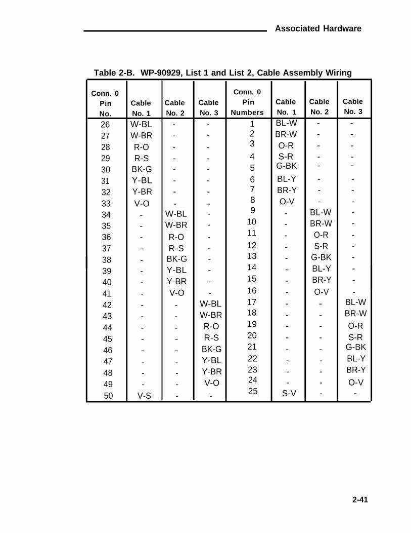
Table 2-B. WP-90929, List 1 and List 2, Cable AssemblyWiring 2-41
Table 2-C. WP-90929, List 3 and List 4, Cable AssemblyWiring 2-44
Table 2-D. Individual Power Supply Adjunct and DistanceLimitations 2-48
Table 2-E. 346A Power Unit Adjunct and Distance Limitations 2-52
-iv-

CHAPTER 2. HARDWARE (66/110-Type)
CHAPTER 2. HARDWARE (66/110-Type)
General
Figure 2-1 shows the equipment required to install a System 75 or 75 XEswitch. This chapter describes the hardware (66- and 110-Type) used inthe installation process. Ordering information is provided for the requiredhardware.
The sites shown in Figure 2-1 are physical locations (closets) forpass-through connections where adjunct power can be applied. Thesatellite location is a place (closet) where cross-connect administrationcan be carried out, and adjunct power can be applied.
2-1

CHAPTER 2. HARDWARE (66/110-Type)
Figure 2-1. Block Diagram of System 75 or 75 XE Installation
2-2

110-Type Hardware Description
110-Type Hardware Description
The 110-type hardware consists of connectorized or field-terminatedterminal blocks in 100-, 300-, and 900-pair sizes. The 110-type terminalblocks consist of the following parts:
●
●
●
110-type wiring blocks
Index strips
3-, 4-, and 5-pair connecting blocks.
110-Type Wiring Blocks
The 110-type wiring block (Figure 2-2) is a plastic wiring block equippedwith permanently attached index strips.
WIRING BLOCK DESIGNATIONINSERT
TERMNO. 1
INDEXSTRIP
TERMNO. 50
Figure 2-2. 110-Type Wiring Block
2-3

CHAPTER 2. HARDWARE (66/110-Type)
Index Strips and Connecting Blocks
The index strips (Figure 2-3) are slotted rows that provide space toterminate 25-pair cables. The wires are placed in the slots in the indexstrip. The standard termination for a 25-pair cable is shown in Table 2-A.
CABLE IS TERMINATEDIN 25-PAIRINDEX STRIP
110-TYPE WIRINGBLOCK (TOP VIEW)
TERMINATIONPOINTS FOR
CROSS-CONNECTIONS(JUMPERS ORPATCH CORDS)
4-PAIRCONNECTINGBLOCK
3-PAIRCONNECTINGBLOCKS
Figure 2-3. 110-Type Index Strip With Connecting Blocks
The connecting blocks (Figure 2-3) are equipped with clips that slice theinsulation of the wires when the connecting block is pushed onto theindex strip. The top of the connecting blocks are used forcross-connections. When a wire is punched onto the top of theconnecting block, it makes a connection, through the connecting block,to the wire in the index strip.
The connecting blocks come in 3-, 4-, and 5-pair blocks. When 3- or4-pair connecting blocks are used, the last connecting block on eachindex strip must be one pair larger to complete the 25-pairs. Theordering codes determine the type of connecting blocks received with aterminal block. The 110-type wiring blocks allow for individual 3- and4-pair connecting blocks to be disconnected for testing withoutdisturbing adjacent circuits.
2-4

110-Type Hardware Description
Table 2-A. 25-Pair Cable Termination on a 110-Type WiringBlock/66-Type Connecting Block
25-Pair Cable
ConnectorPin Pair Color
110-Type66-Type
Wiring/ConnBlock
TerminalsNumbers
2 6 W-BL 1
11
BL-W 2
27 W-O 3
22
O-W 4
283
W-G 5
3 G-W 6
29 W-BR 74
4 BR-W 8
30 W-S 9
55
S-W 10
31 R-BL 11
66 BL-R 12
32 R-O 13
77
O-R 14
33 R-G 15
88 G-R 16
34 R-BR 179
9BR-R 18
35 R-S 1910
10 S-R 20
2-5

CHAPTER 2. HARDWARE (66/110-Type)
Table 2-A. 25-Pair Cable Termination on a 110-Type WiringBlock/66-Type Connecting Block (Contd)
25-Pair Cable 110-Type66-Type
Wiring/ConnConnector Block
Pin Pair Color TerminalsNumbers
36113712381339144015
11
122324
13
BK-BLBL-BKBK-OO-BKBK-GG-BK
BK-BRBR-BKBK-SS-BK
252627282930
2122
14
15
16
17
18
19
41164217431844194520
Y-BLBL-YY-OO-YY-GG-Y
Y-BRBR-YY-SS-Y
313233343536373839
20 40
2-6

110-Type Hardware Description
Table 2-A. 25-Pair Cable Termination on a 110-Type WiringBlock/66-Type Connecting Block (Contd)
25-Pair Cable 110-Type66-Type
ConnectorWiring/Conn
BlockPin Pair Color Terminals
Numbers
46 V-BL 4121
21 BL-V 4247
22V-O 43
22 O-V 4448
23V-G 45
23 G-V 4649
24V-BR 47
24 BR-V 4850
25V-S 49
25 S-V 50
The 110-type hardware consists of 110A- and 110P-type hardware. The110P-type hardware uses patch cords to make cross-connections. Thisallows the customer to make cross-connections. The 110A-typehardware uses individual jumper wires for cross-connections. For thisreason, the 110A-type hardware is not intended for customer usagebecause it requires technically skilled personnel to makecross-connections. The 110A- and 110P-type hardware should not bemixed together in the same room.
110A-Type Hardware
The 110A-type hardware consists of a 100- or 300-pair wiring block andthe associated connecting blocks. The 100-pair wiring blocks (Figure2-4) are arranged for field termination. The 300-pair wiring blocks(Figure 2-5) come in both field-terminated and connectorized (with6-foot cable stubs) types.
2-7

CHAPTER 2. HARDWARE (66/110-Type)
Figure 2-4. 110A-Type 100-Pair Terminal Block
2-8

110-Type Hardware Description
Figure 2-5. 110A-Type 300-Pair Terminal Block
2-9

CHAPTER 2. HARDWARE (66/110-Type)
The 110A-type hardware can be used for the trunk/auxiliary field and alldistribution fields (port, auxiliary, and station). The following 110A-typehardware is available.
●
●
●
●
110AE1-75FT terminal block—A kit of parts for field terminationof cables on a 100-pair wiring block (110AW1-100). It providesspace to terminate 8 three-pair and 12 four-pair circuits.
110AB1-100FT terminal block—A kit of parts for field terminationof cables on a 100-pair wiring block (110AW1-100). It providesspace to terminate 24 four-pair circuits.
110AC1-100FT terminal block—A kit of parts for field terminationof cables on a 100-pair wiring block (110AW1-100). It providesspace to terminate 32 three-pair circuits.
110AB1-300FT terminal block—A kit of parts for field terminationof cables on a 300-pair wiring block (110AW1-300). It providesspace to terminate 72 four-pair circuits.
●
●
●
110AC1-300FT terminal block—A kit of parts for field terminationof cables on a 300-pair wiring block (110AW1-300). It providesspace to terminate 96 three-pair circuits.
110AC1-300STF/6 terminal block—A factory-assembled 300-pairconnectorized terminal block that provides space to terminate 96three-pair circuits. Twelve, 25-pair (6-foot long), cables equippedwith female connectors exit from the top of the block. The 25-paircables are factory-terminated on the wiring block in continuousnumerical order.
110AC1-300STM/6 terminal block—A factory-assembled 300-pairconnectorized terminal block that provides space to terminate 96three-pair circuits. Twelve, 25-pair (6-foot long), cables equippedwith male connectors exit from the top of the block. The 25-paircables are factory-terminated on the wiring block in continuousnumerical order.
The 110AW1-100 or 110AW1-300 wiring blocks can be orderedseparately. Also, the 3- or 4-pair connecting blocks (110C-3 or 110C-4,respectively) must be ordered separately.
2-10

110-Type Hardware Description
110A-TYPE HARDWARE ORDERING INFORMATION
Description
110AE1-75FT Terminal Block
110AB1-100FT Terminal Block
110AC1-100FT Terminal Block
110AB1-300FT Terminal Block
110AC1-300FT Terminal Block
110AC1-300STF/6 Terminal Block
110AC1-300STM/6 Terminal Block
110AW1-100 Wiring Block
110AW1-300 Wiring Block
110C-3 3-Pair Connecting Block
110C-4 4-Pair Connecting Block
110P-Type Hardware
Comcode
104 049 093
103 823 845
103 826 780
104 049 051
104 049 069
104 049 077
104 049 085
103 804 894
103 804 902
103 801 239
103 801 247
The 110P-type hardware consists of 100-pair wiring blocks, separatedby horizontal patch cord troughs, mounted on a panel. The P-typecomes in both 300- and 900- pair configurations which can either beconnectorized or field terminated. The 110P-type terminal blocks aremade up of alternate rows of 110-type wiring blocks and horizontaljumper troughs arranged in a vertical column with the troughs locatedabove the wiring blocks. At the bottom of the terminal block is a partiallyclosed duct. The field-terminated hardware must be assembled (troughsand wiring blocks must be fastened to the back panel); the connectorizedterminals come fully assembled and ready for mounting. A 300-pairconnectorized terminal block is shown in Figure 2-6.
There are two types of 900-pair connectorized terminal blocks: one hasa connector field at the top; the other is connectorized with a 40-inchlength of cable terminated with a female 25-pair cable at the bottom(Figures 2-7 and 2-8).
2-11

CHAPTER 2. HARDWARE (66/110-Type)
25-PAIRCONNECTORNUMBER 12
25-PAIRCONNECTORNUMBER 1
25-PAIRINDEX STRIPS
LABELS110-TYPE 100-PAIRWIRING BLOCK
INDEX STRIPS 1-4
INDEX STRIPS 5-8
HORIZONTAL WIRE TROUGH
INDEX STRIPS 9-12
Figure 2-6. 110P-Type Terminal Block—300-Pair Connectorized
2-12

110-Type Hardware Description
25-PAIRCONNECTORNUMBER 12 25-PAIR
CONNECTORNUMBER 1
25-PAIRCONNECTORNUMBER 36
25-PAIRCONNECTORNUMBER 25
INDEXSTRIPS1-4
INDEXSTRIPS5-8
25-PAIRINDEX STRIPS
LABELSINDEXSTRIPS9-12
110-TYPE 100-PAIRWIRING BLOCK
INDEXSTRIPS13-16
INDEXSTRIPS17-20
INDEXSTRIPS21-24
HORIZONTAL WIRE TROUGHINDEXSTRIPS25-28
INDEXSTRIPS29-32
INDEXSTRIPS33-36
Figure 2-7. 110P-Type Terminal Block—900-Pair Connectorized(Top)
2-13

CHAPTER 2. HARDWARE (66/110-Type)
25-PAIRINDEX STRIPS
LABELS110-TYPE 100-PAIRWIRING BLOCK
INDEXSTRIPS1-4
INDEXSTRIPS5-8
INDEXSTRIPS
13-16HORIZONTAL WIRE TROUGH
INDEX
36 CONNECTORS
9-12
INDEXSTRIPS
STRIPS17-20
INDEXSTRIPS21-24
INDEXSTRIPS25-28
INDEXSTRIPS29-32
INDEXSTRIPS33-36
Figure 2-8. 110P-Type Terminal Block—900-Pair Connectorized(Bottom)
2-14

110-Type Hardware Description
The 110P-type hardware can be used for the trunk/auxiliary field and alldistribution fields (port, auxiliary, and station). The following 110P-typehardware is available.
●
●
●
●
●
●
110PB1-300CT terminal block—A factory-assembled 300-pairconnectorized terminal block that provides space to terminate 72four-pair circuits. Twelve, 25-pair, female, miniature ribbonconnectors are mounted at the top of the terminal block. Theconnectors are factory-terminated on the wiring block incontinuous numerical order.
110PC1-300CT terminal block—A factory-assembled 300-pairconnectorized terminal block that provides space to terminate 96three-pair circuits. Twelve, 25-pair, female, miniature ribbonconnectors are mounted at the top of the terminal block. Theconnectors are factory-terminated on the wiring block incontinuous numerical order.
110PB1-300FT terminal block—A kit of parts for field terminationof cables on a 300-pair wiring block. It provides space to terminate72 four-pair circuits.
110PC1-300FT terminal block—A kit of parts for field terminationof cables on a 300-pair wiring block. It provides space to terminate96 three-pair circuits.
110PE1-300CT terminal block—A factory-assembled, 300-pair,connectorized, terminal block that provides space to terminate 32three-pair and 48 four-pair circuits. Twelve, 25-pair, female,miniature ribbon connectors are mounted at the top of theterminal block. The connectors are terminated on the wiringblocks in continuous numerical order.
110PE1-300CT/FT terminal block—A partially factory-assembled300-pair terminal block that provides space to terminate 32three-pair and 48 four-pair circuits. Four, 25-pair, female,miniature, ribbon connectors are mounted at the top of theterminal block. The connectors are terminated on the 3-pair wiringblock in continuous numerical order. The 4-pair wiring blocks areavailable as a kit of parts to allow field termination of the 4-paircircuits.
2-15

CHAPTER 2. HARDWARE (66/110-Type)
●
●
●
●
●
●
●
110PE1-300FT terminal block—A kit of parts for field terminationof cables on a 300-pair terminal block. It provides space toterminate 32 three-pair and 48 four-pair circuits.
110PB1-900CB terminal block—A factory-assembled, 900-pair,connectorized, terminal block that provides space to terminate216 4-pair circuits. Thirty-six, 25-pair cables (40-inches long),equipped with female miniature ribbon connectors, are mountedat the bottom of the terminal block. The cables arefactory-terminated on the wiring blocks in continuous numericalorder.
110PC1-900CB terminal block—A factory-assembled 900-pairconnectorized terminal block that provides space to terminate288 three-pair circuits. Thirty-six, 25-pair cables (40-inches long),equipped with female miniature ribbon connectors, are mountedat the bottom of the terminal block. The cables arefactory-terminated on the wiring blocks in continuous numericalorder.
110PB1-900CT terminal block—A factory-assembled 900-pairconnectorized terminal block that provides space to terminate216 four-pair circuits. Thirty-six, 25-pair, female, miniature ribbonconnectors are mounted at the top of the terminal block. Theconnectors are factory-terminated on the wiring blocks incontinuous numerical order.
The 110PC1-900CT terminal block—a factory-assembled 900-pairconnectorized terminal block that provides space to terminate288 three-pair circuits. Thirty-six, 25-pair, female, miniature ribbonconnectors are mounted at the top of the terminal block. Theconnectors are factory-terminated on the wiring blocks incontinuous numerical order.
110PB1-900FT terminal block—A kit of parts for field terminationof cables on a 900-pair terminal block. It provides space toterminate 216 four-pair circuits.
110PC1-900FT terminal block—A kit of parts for field terminationof cables on a 900-pair terminal block. It provides space toterminate 288 three-pair circuits.
2-16

110-Type Hardware Description
●
●
110PE1-900CT/FT terminal block—A partially factory-assembled900-pair terminal block that provides termination space for 96three-pair and 144 four-pair circuits. Twelve, 25-pair, female,miniature, ribbon connectors are mounted at the top of theterminal block. The connectors are terminated on the 3-pair wiringblocks in a continuous numerical order. The 4-pair wiring blocksare available as a kit of parts to allow field termination of the 4-paircircuits.
110PE1-900FT terminal block—A kit of parts for field terminationof cables on a 900-pair terminal block. It provides space toterminate 96 three-pair and 144 four-pair circuits.
110P-TYPE HARDWARE ORDERING INFORMATION
Description
110PB1-300CT Terminal Block
110PC1-300CT Terminal Block
110PB1-300FT Terminal Block
110PC1-300FT Terminal Block
110PE1-300CT Terminal Block
110PE1-300CT/FT Terminal Block
110PE1-300FT Terminal Block
110PB1-900CB Terminal Block
110PC1-900CB Terminal Block
110PB1-900CT Terminal Block
110PC1-900CT Terminal Block
110PB1-900FT Terminal Block
110PC1-900FT Terminal Block
110PE1-900CT/FT Terminal Block
110PE1-900FT Terminal Block
Comcode
103 823 886
103 804 852
103 804 829
103 804 860
104 017 066
104 173 166
103 823 902
104 173 158
104 166 590
103 804 837
103 048 878
103 804 845
103 804 886
104 173 174
103 823 910
2-17

CHAPTER 2. HARDWARE (66/110-Type)
188-Type Backboards
The 188-type backboards are wire troughs that channel the patch cordsor cross-connecting wire between the wiring blocks. The backboardsconsist of a metal frame equipped with retaining rings. They areavailable in four types:
●
●
●
●
The 188B1 backboard is a horizontal wire trough that is used with110A-type terminal blocks.
The 188C2 backboard is a vertical wire trough that is used with900-pair 110P-type terminal blocks.
The 188D2 backboard is a vertical wire trough that is used with300-pair 110P-type terminal blocks.
The 188E2 backboard is a horizontal wire trough that is usedbetween the trunk/auxiliary field and the distribution field foreither 300- or 900-pair 110P-type terminal blocks.
188-TYPE BACKBOARD ORDERING INFORMATION
Description Comcode
188B1 Backboard 102 689 569
188C2 Backboard 104 031 794
188D2 Backboard 104 032 404
188E2 Backboard 104 031 802
Cords
110-Type Patch Cords
The 1-pair and 3-pair patch cords (Figure 2-9) are used to cross-connectterminals to switch ports at the cross-connect field. The patch cords areavailable in several lengths. The patch cords are equipped with a plasticplug on each end. The plastic plugs are compatible with the 110-typeconnecting blocks used on the wiring blocks. The patch cords are keyedso that they cannot be inserted upside down or on a split pair.
2-18

110-Type Hardware Description
PLUGS
Figure 2-9. 3-Pair Patch Cord Used With 110-Type Hardware
110-TYPE PATCH CORD ORDERING INFORMATION
Cord Description Length Comcode Comcode(1 per package) (10 per package)
F-61679-2F-61679-3F-61679-4F-61679-5F-61679-6F-61679-7F-61679-8F-61679-9F-61679-19110P6A2B110P6A3B110P6A4B110P6A5B110P6A6B110P6A7B110P6A8B110P6A9B110P6A19B
1-Pair1-Pair1-Pair1-Pair1-Pair1-Pair1-Pair1-Pair1-Pair3-Pair3-Pair3-Pair3-Pair
2 ft3 ft4 ft5 ft6 ft7 ft8 ft9 ft19 ft2 ft3 ft4 ft5 ft
103 991 873103 991 881103 991 899103 991 907103 991 915103 991 923103 991 931103 991 949103 991 956Not AvailableNot AvailableNot AvailableNot Available
Not AvailableNot AvailableNot Available104 073 606Not AvailableNot AvailableNot Available104 073 614104 073 622103 882 965103 882 957103 882 940103 882 973
3-Pair 6 ft Not Available 103 882 9323-Pair 7 ft Not Available 103 882 9243-Pair 8 ft Not Available 103 882 9163-Pair 9 ft Not Available 103 882 9083-Pair 19 ft Not Available 103 882 890
2-19

CHAPTER 2. HARDWARE (66/110-Type)
F-61789 Power Adapter Cords
The F-61789 power adapter cord (Figure 2-10) is used at the equipmentroom or satellite closet cross-connect field to connect an adjunct powersupply to a 4-pair connecting block that is mounted on a 110-type wiringblock. The power adapter cord is a 1-pair cable equipped with a6-conductor modular plug on one end, and a 1-pair, 110-type patch cordplug on the other end. The modular plug connects to an adjunct powersupply, and the patch cord plug connects to a connecting blockmounted on a 110-type wiring block.
1-PAIRPLUG
MODULARPLUG
Figure 2-10. F-61789 Power Adapter Cord
POWER ADAPTER CORD ORDERING INFORMATION
Cord Length Comcode Comcode
(1 per package) (10 per package)
F-61789-5 5 ft 103 907 184 103 891 800
F-61789-9 9 ft 103 907 192 103 891 792
F-61789-19 19 ft 103 907 200 103 891 784
2-20

110-Type Hardware Description
Test Cords
The D test cord provides test access to one pair of wires withoutremoving any jumpers.
D TEST CORD ORDERING INFORMATION
LengthCordD Test Cord 4 ft 402 023 949D Test Cord 8 ft 402 023 956
Comcode
Jumpers
Solid wire jumpers can be used to make cross-connections instead ofthe 1- and 3-pair patch cords. The jumpers are terminated on theconnecting blocks with an impact tool.
Jumper WireJUMPER WIRE ORDERING INFORMATION
Description Comcode(Order by Footage)
DT 24M-Y/BL/R/G 2-Pair 103 252 557
DT 24P-W/BRN 1-Pair 102 484 045
DT 24P-Y/BL 1-Pair 102 379 195
DT 24P-Y/G 1-Pair 103 252 565
DT 24P-Y/O 1-Pair 103 252 573
DT 24P-Y/R 1-Pair 103 252 581
Tools
The following tools are required terminate the wires/jumpers onfield-terminated wiring blocks:
●
●
●
The D impact tool (AT-8762) is a single-wire termination tool
The 788J1 impact tool will terminate five pairs of wire at a time
The 788K1 conductor retention tool is used to secure cable pairsin the wiring blocks when connecting blocks are being removedfrom the wiring blocks.
2-21

CHAPTER 2. HARDWARE (66/110-Type)
110-TYPE TOOLS ORDERING INFORMATION
Description Comcode
D Impact Tool 402 024 723
788J1 Impact Tool 102 648 839
788K1 Conductor Retention Tool 102 655 495
F Clip Terminal Insulator
The F clip terminal insulator (AT-8660F) is used to identify specialcircuits. Each insulator identifies one pair and may be located inadjacent pair positions without interference.
F CLIP TERMINAL INSULATOR ORDERING INFORMATION
Description Comcode
F Clip Terminal Insulator 401 149 802
Designation Strips
Designation strips (Figure 2-11) are made of clear plastic and snap intoalternate rows of the 110-type wiring block. Each designation strip canidentify 50-pairs of wire. The designation strips accept the standard110-labels that are ordered separately. The designation strips arefurnished with the 110-type terminal blocks, but they can also beordered separately.
DESIGNATION STRIP ORDERING INFORMATION
Description Qty. Per Code Comcode
188&T1-50 Designation Strip 6 103 895 504
2-22

66-Type Hardware Description
CLEAR PLASTICDESIGNATIONSTRIP
Figure 2-11. Designation Strip
66-Type Hardware Description
The 66-type hardware consists of non-connectorized or connectorizedconnecting blocks. The connecting blocks can be mounted individuallyor in multiple arrangements. All 66-type hardware uses the same basicconnecting block, a 66M1-50.
66M1-50 Connecting Block
The 66M1-50 (Figure 2-12) connecting block is a plastic connectingblock containing quick connect terminals sized to terminate 20 to 24gauge wire. It has 50 rows of terminals with four terminals in each row.The first two and last two terminals of each row are connected togetherand each row is split between the second and third terminals (Figure2-12). These terminals provide space to terminate one 25-pair cable andthe associated jumpers. The terminals slice the insulation of the wireswhen the wires are punched onto the terminals. The standardtermination for a 25-pair cable on a 66M1-50 connecting block is shownin Table 2-A. The 66M1-50 connecting block can be mounted directly on
2-23

CHAPTER 2. HARDWARE (66/110-Type)
the wall or on a backboard. These connecting blocks are used in theequipment room for the distribution field.
(Figure 2-13) connecting block. It consists of a 66M1-50 connectingblock prewired to a 50-pin connector mounted on each side of the
Figure 2-12. 66M1-50 Connecting Block
Connectorized 66-Type Connecting Blocks
The connectorized version of the 66-type connecting block is the 157B
2-24

66-Type Hardware Description
connecting block. Each 157B connecting block can terminate two25-pair cables. It can be mounted directly on the wall or on a backboard.These connecting blocks are used in the equipment room for thetrunk/auxiliary and distribution fields.
Figure 2-13. 157B Connecting Block
Multiple-Mounted 66-Type Connecting Blocks
Connectorized 66-type connecting blocks are available in two multiplemounting arrangements. The 166-type backboard consists of eight157B connecting blocks factory-mounted on a purple backboard. Thismultiple arrangement provides space to terminate sixteen 25-paircables. The 166-type backboard is used in the equipment room for thetrunk/auxiliary field and distribution field.
2-25
CHAPTER 2. HARDWARE (66/110-Type)
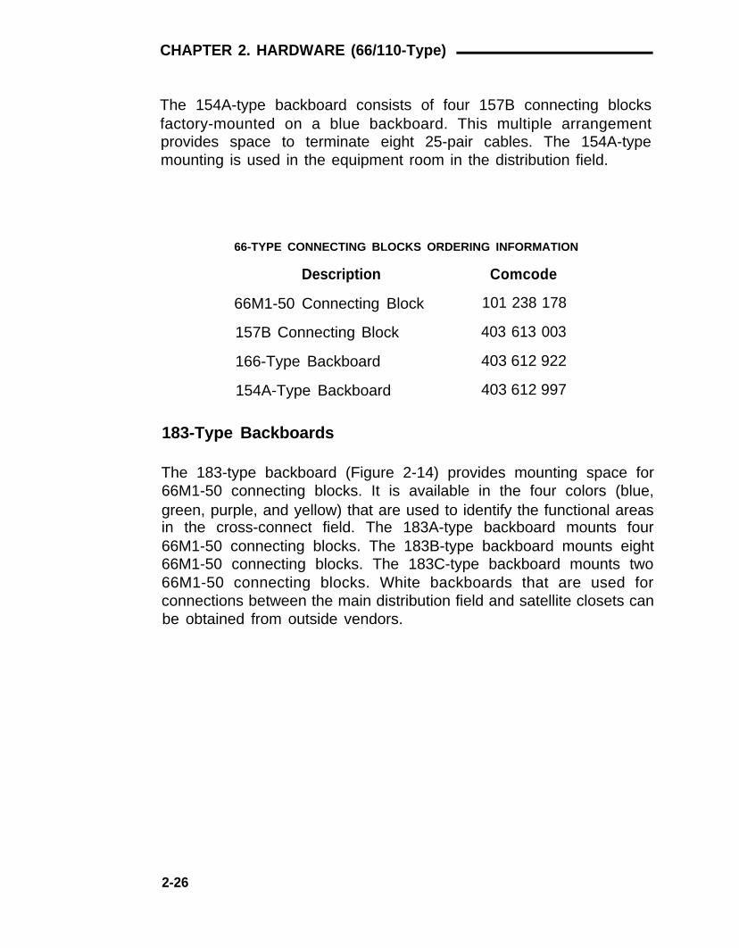
The 154A-type backboard consists of four 157B connecting blocksfactory-mounted on a blue backboard. This multiple arrangementprovides space to terminate eight 25-pair cables. The 154A-typemounting is used in the equipment room in the distribution field.
66-TYPE CONNECTING BLOCKS ORDERING INFORMATION
Description Comcode
66M1-50 Connecting Block 101 238 178
157B Connecting Block 403 613 003
166-Type Backboard 403 612 922
154A-Type Backboard 403 612 997
183-Type Backboards
The 183-type backboard (Figure 2-14) provides mounting space for66M1-50 connecting blocks. It is available in the four colors (blue,green, purple, and yellow) that are used to identify the functional areasin the cross-connect field. The 183A-type backboard mounts four66M1-50 connecting blocks. The 183B-type backboard mounts eight66M1-50 connecting blocks. The 183C-type backboard mounts two66M1-50 connecting blocks. White backboards that are used forconnections between the main distribution field and satellite closets canbe obtained from outside vendors.
2-26

66-Type Hardware Description
Figure 2-14. 183A-Type Backboard
183-TYPE BACKBOARD ORDERING INFORMATION
Code Color Mounts Comcode
183A1 Blue (4) 66M1-50 101 412 963 Conn Blocks
183A2 Green (4) 66M1-50 101 412 971Conn Blocks
183A4 Purple (4) 66M1-50 101 937 902Conn Blocks
183A5 Yellow (4) 66M1-50 101 986 446Conn Blocks
183B1 Blue (8) 66M1-50 101 412 989Conn Blocks
183B2 Green (8) 66M1-50 101 564 631Conn Blocks
183B4 Purple (8) 66M1-50 101 937 928Conn Blocks
183B5 Yellow (8) 66M1-50 101 986 453Conn Blocks
183C1 Blue (2) 66M1-50 103 222 790Conn Blocks
2-27

CHAPTER 2. HARDWARE (66/110-Type)
187B1 Backboard
The 187B1 backboard (Figure 2-15) provides 16 pegs that are used todress the cross-connecting wire between connecting blocks. The187B1 backboards can be used with any arrangement of 66-typeconnecting blocks.
Figure 2-15. 187B1 Backboard
187B1 BACKBOARD ORDERING INFORMATION
Description Comcode
187B1 Backboard 101 937 944
Power Adapter Cords
The power adapter cord (Figure 2-16) connects an adjunct powersupply to a 4-pair station circuit terminated on a 66-type connectingblock. The cord consists of a 2-pair cable equipped with a 6-conductormodular plug. The plug end connects to the power supply and the otherend terminates on the 66-type connecting block.
2-28

66-Type Hardware Description
MODULARPLUG
Figure 2-16. Power Adapter Cord
POWER ADAPTER CORD ORDERING INFORMATION
Length Comcode10 ft 103 935 62325 ft 103 895 660
Jumpers
Solid wire jumpers are used for cross-connections between terminalson the connecting blocks. The jumpers are punched down on theconnecting blocks with a termination tool.
JUMPER WIRE ORDERING INFORMATION
Jumper Wire Description Comcode(Order by Footage)
DT 24M-Y/BL/R/G 2-Pair 103 252 557
DT 24P-W/BRN 1-Pair 102 484 045
DT 24P-Y/BL 1-Pair 102 379 195
DT 24P-Y/G 1-Pair 103 252 565
DT 24P-Y/O 1-Pair 103 252 573
DT 24P-Y/R 1-Pair 103 252 581
2-29

CHAPTER 2. HARDWARE (66/110-Type)
Tools
The following tools are used to terminate or remove the wire on theconnecting blocks:
●
●
●
The 714B tool is a nonimpact single-wire termination tool
The D impact tool (AT-8762) is a single-wire impact terminationtool
The 724A tool is used to remove wires from the connectingblocks.
66-TYPE TOOLS ORDERING INFORMATION
Description Comcode714B Tool 100 755 511Blade AT-8762 402 024 681D Impact Tool 402 024 723724A Tool 100 755 636
Bridging Clips
Bridging clips are spring clips that connect two adjacent terminals in thesame terminal row on a connecting block. Bridging clips provide thefastest, most reliable way to make cross-connections. No special toolsare required to install or remove the clips.
BRIDGING CLIPS ORDERING INFORMATION
Description Comcode
BCSS-2 Bridging Clip 403 596 035
2-30

Associated Hardware
Associated Hardware
Cable Slack Managers
General
The cable slack managers (Figure 2-17) are raised floor units that areused for cable distribution and cable slack storage between the switchcabinets and the cross-connect field. They can also accommodate alimited amount of slack in station cables. Power cables from the switchcabinets are also run through/from the cable slack managers.
Note: Cable slack managers are not required when the switchcabinet is installed on a raised computer floor. The station cablesand the cables from the switch cabinets are routed under thecomputer flooring to the cross-connect field.
The cable slack managers have tabs and interlocks that allow adjacentcable slack managers to interlock together. Retainers mounted oncolumns inside the cable slack managers keep the cables fromprotruding above the top of the base. The cable slack managers arecoded as housings and two types are available.
2-31

CHAPTER 2. HARDWARE (66/110-Type)
Z814ACOVER
Z814ACOVER
Z8A1 BASE
Z6A RETAINER
Z113A HOUSING
Z814ACOVER
Z815ACOVER
Z8A1 BASE
Z114A HOUSING
Figure 2-17. Cable Slack Managers
2-32

Associated Hardware
Z113A Housing
The Z113A housing is used between the wall and equipment cabinets(switch, AP, auxiliary, etc.). It consists of:
●
●
●
(1) Z8A1 base
(2) Z814A covers
(25) Z6A retainers.
Z114A Housing
The Z114A housing is designed to be used adjacent to the Z113Ahousing if no equipment cabinet exists at the position or if the cabinet(s)is positioned against the wall with the cross-connect field beside thecabinet(s). It consists of:
●
●
●
●
(1) Z8A1 base
(1) Z814A cover
(1) Z815A cover
(25) Z6A retainers.
CABLE SLACK MANAGER ORDERING INFORMATION
Description ComcodeZ113A Housing 103 961 322Z114A Housing 103 961 330Z8A1 Base 103 965 133Z814A Cover 103 965 141Z815A Cover 103 965 158Z6A Retainer 103 965 166
2-33

CHAPTER 2. HARDWARE (66/110-Type)
Network Interfaces
RJ21X Network Interface
The RJ21X network interface is the connection point between the localtelephone company lines (1-pair trunks) and the switch. The interface issupplied and installed by the local telephone company. See Table 3-Gfor network interface pin assignments on CO and DID trunk circuitpacks.
RJ2GX Network Interface
The RJ2GX network interface is the connection point between the localtelephone company tie-trunks and the switch three-pair tie-trunks. Theinterface is supplied and installed by the local telephone company. SeeTable 3-G for network interface pin assignments on tie trunk circuitpacks.
1.544 Mbps Digital Service Interface
The 1.544 Mbps (megabits per second) digital service interface is theconnection point between the local telephone company T1 carrier linesand the switch DS1 trunks. The interface is supplied and installed by thelocal telephone company.
Sneak Fuse Panels
575-4 Sneak Current Fuse Panel
Sneak current protection is required between the RJ21X or RJ2GXnetwork interface and the switch for both trunk and off-premises circuitpacks. See Installing Off-Premises Voice Terminal Wiring in Chapter 4.The Model 575-4 sneak current fuse panel (Figure 2-18), or equivalent,is recommended for sneak current protection. The panel isconnectorized with incoming and outgoing connectors and equippedwith 25 two-pair fuse modules. Connector cables (B25A) connect thenetwork interface to the sneak fuse panel. Also, 157B connectingblocks equipped with SCP-1 protectors can be used for sneak currentprotection.
2-34

Associated Hardware
Note: Sneak current protectors with a rating of 350 ma at 600Vmust be UL rated for domestic installation and CSA certified forCanadian installation.
SNEAK FUSE PANEL ORDERING INFORMATION
Description Comcode157B Connecting Block 403 613 003SCP-1 Protector* 403 617 632575-4 Sneak Current Fuse Panel 402 989 016
*The SCP-1 protectors must be ordered separately and installed on the 157Bconnecting block. Twenty-four protectors are required per block.
2-35

CHAPTER 2. HARDWARE (66/110-Type)
FUSE
25-PAIRMALECONNECTORIN
MODULE
25-PAIRFEMALECONNECTOROUT
Figure 2-18. Model 575-4 Sneak Fuse Panel
2-36

Associated Hardware
Emergency Transfer Units
General
The emergency transfer units used with the 66-type/110-type hardwareare the Z1A emergency transfer unit and the 574-5 power transfer unit.The units mount on the plywood backboard to the left of thetrunk/auxiliary field.
Z1A Emergency Transfer Unit
The Z1A emergency transfer unit provides emergency transferconnections for six telephones. If the central office (CO) trunks requireground start, a ground start key must be installed on each emergencytransfer telephone.
574-5 Power Transfer Unit
The 574-5 power transfer unit (Figure 2-19) provides power transferconnections for five telephones. This unit provides automatic groundstart.
2-37

CHAPTER 2. HARDWARE (66/110-Type)
MFG. BY PORTA SYSTEMS
TRUNK LINE EXT
MODEL 574-5PAT PENDING
Figure 2-19. Model 574-5 Power Transfer Unit
2-38

Associated Hardware
Trunk Concentrator Cables
Trunk concentrator cables are used for the following purposes:
●
●
To match 1-pair local telephone company trunks to 3-pair switchcircuits at the cross-connect field.
To match 1-pair local telephone company trunks provided foroff-premises lines to 3-pair switch circuits at the cross-connectfield.
● To split eight 3-pair analog tie trunks into two groups of four3-pair tie trunks.
The trunk concentrator cables are 25 feet long. They are coded as cableassemblies and described in the following sections.
Note: The WP-90929, List 1 and List 3 cable assemblies are usedwith 110-type hardware, while List 2 and 4 cable assemblies areused with 66-type hardware.
WP-90929, List 1, Cable Assembly (For 110-type Hardware Only)
The WP-90929, List 1, cable assembly (Figure 2-20 and Table 2-B)provides a way to connect local telephone company trunks to theswitch. It can also be used to connect off-premises analog trunksbetween the port field and trunk field at the equipment roomcross-connect field. All the ribbon connectors on the cable assemblyare male-type connectors. Each cable assembly can match twenty-four1-pair trunk circuits with twenty-four 3-pair trunk circuits.
2-39

CHAPTER 2. HARDWARE (66/110-Type)
CONNECTSTO 110TERMINALBLOCKCONNECTOR
CONNECTSTO 110TERMINALBLOCKCONNECTOR
CONNECTOR "O"
LIST 1 CABLE
CONNECTOR "O"
LIST 3 CABLE
LEGEND:M = 25-PAIR MALE CONNECTORF = 25-PAIR FEMALE CONNECTOR
CONNECTSTO SWITCHCABINET
CONNECTSTO SWITCHCABINET
Figure 2-20. Trunk Concentrator Cables (WP-90929, L1 & L3) (For110-type Hardware Only)
2-40
Associated Hardware
Table 2-B. WP-90929, List 1 and List 2, Cable Assembly Wiring
Conn. 0 Conn. 0
Pin Cable Cable Cable Pin Cable Cable Cable
No. No. 1 No. 2 No. 3 Numbers No. 1 No. 2 No. 3
26 W-BL - - 1 BL-W - -
27 W-BR - - 2 BR-W - -
28 R-O - - 3 O-R - -
29 R-S - - 4 S-R - -
30 BK-G - - 5 G-BK - -
31 Y-BL - - 6 BL-Y - -
32 Y-BR - - 7 BR-Y - -
33 V-O - - 8 O-V - -
34 - W-BL - 9 - BL-W -
35 - W-BR - 10 - BR-W -
36 - R-O - 11 - O-R -
37 - R-S - 12 - S-R -
38 - BK-G - 13 - G-BK -
39 - Y-BL - 14 - BL-Y -
40 - Y-BR - 15 - BR-Y -
41 - V-O - 16 - O-V -
42 - - W-BL 17 - - BL-W
43 - - W-BR 18 - - BR-W
44 - - R-O 19 - - O-R
45 - - R-S 20 - - S-R
46 - - BK-G 21 - - G-BK
47 - - Y-BL 22 - - BL-Y
48 - - Y-BR 23 - - BR-Y
49 - - V-O 24 - - O-V
50 V-S - - 25 S-V - -
2-41

CHAPTER 2. HARDWARE (66/110-Type)
WP-90929, List 2, Cable Assembly (For 66-type Hardware Only)
The WP-90929, List 2, cable assembly (Figure 2-21 and Table 2-B)provides a way to connect local telephone company trunks to theswitch. It can also be used to connect off-premises analog trunksbetween the port field and trunk field at the equipment roomcross-connect field. The 3-fingered end of the cable assembly isequipped with male-type ribbon connectors. The other end of the cableassembly is equipped with a female-type ribbon connector. Each cableassembly can match twenty-four 1-pair trunk circuits with twenty-four3-pair trunk circuits.
2-42

Associated Hardware
CONNECTSTO 66-TYPECONNECTINGBLOCK
CONNECTSTO 66-TYPECONNECTINGBLOCK
CONNECTOR "O"
LIST 2 CABLE
CONNECTSTO SWITCHCABINET
CONNECTSTO SWITCHCABINET
CONNECTOR "O"
LIST 4 CABLE
LEGEND:M = 25-PAIR MALE CONNECTORF = 25-PAIR FEMALE CONNECTOR
Figure 2-21. Trunk Concentrator Cables (WP-90929, L2 & L4) (For66-type Hardware Only)
WP-90929, List 3, Cable Assembly (For 110-type Hardware Only)
The WP-90929, List 3, cable assembly (Figure 2-20 and Table 2-C)provides a way to connect tie-trunk circuits to the switch. All ribbonconnectors on the cable assembly are male-type connectors. Eachcable assembly can match eight 3-pair tie-trunk circuits with two groupsof four 3-pair tie-trunk circuits.
2-43

CHAPTER 2. HARDWARE (66/110-Type)
Table 2-C. WP-90929, List 3 and List 4, Cable Assembly Wiring
Conn. 0 Conn. 0Pin Cable Cable Pin Cable Cable
No. No. 1 No. 2 Numbers No. 1 No. 2
26 W-BL - 1 BL-W -27 W-O - 2 O-W -28 W-G - 3 G-W -29 W-BR - 4 BR-W -30 W-S - 5 S-W -31 R-BL - 6 BL-R -32 R-O - 7 O-R -33 R-G - 8 G-R -34 R-BR - 9 BR-R -35 R-S - 10 S-R -36 BK-BL - 11 BL-BK -37 BK-O - 12 O-BK -
38 - W-BL 13 - BL-W39 - W-O 14 - O-W40 - W-G 15 - G-W41 - W-BR 16 - BR-W42 - W-S 17 - S-W43 - R-BL 18 - BL-R44 - R-O 19 - O-R45 - R-G 20 - G-R46 - R-BR 21 - BR-R
47 - R-S 22 - S-R
48 - BK-BL 23 - BL-BK
49 - BK-O 24 - O-BK
50 V-S 25 S-V -
2-44

Associated Hardware
WP-90929, List 4, Cable Assembly (For 66-type Hardware Only)
The WP-90929, List 4, cable assembly (Figure 2-21 and Table 2-C)provides a way to connect tie-trunk circuits to the switch. The 2-fingeredend of the cable assembly is equipped with male-type ribbon connectors.The other end of the cable assembly is equipped with a female-typeribbon connector. Each cable assembly can match eight 3-pair tie-trunkcircuits with two groups of four 3-pair tie-trunk circuits.
TRUNK CONCENTRATOR CABLE ORDERING INFORMATION
Description Comcode
WP-90929, List 1, Cable Assembly 405 064 999
WP-90929, List 2, Cable Assembly 405 065 012
WP-90929, List 3, Cable Assembly 405 075 482
WP-90929, List 4, Cable Assembly 405 075 540
16-Port Analog Line Circuit Pack Adapter Cable (For110-Type Hardware Only)
The 16-port analog line circuit pack (TN746) contains sixteen 1-paircircuits that appear on a 25-pair connector at the switch. The 16-portanalog line adapter cable (Figure 2-21) separates the 1-pair circuits(from the switch) into 3-pair circuits that appear on two 25-pairconnectors at the other end of the cable.
2-45

CHAPTER 2. HARDWARE (66/110-Type)
CONNECTSTO 16-PORTANALOGLINECIRCUITPACK
CONNECTSTO CROSS-CONNECTFIELD(NOTE)
LEGEND:M = 25-PAIR MALE CONNECTORF = 25-PAIR FEMALE CONNECTOR
NOTE: AN A25D CABLE MUST BE USED BETWEENTHE ADAPTER CABLE AND THE 110-TYPETERMINAL BLOCK.
Figure 2-22. 16-Port Analog Line Circuit Pack Adapter Cable (853BAdapter)
The adapter cable is 8 feet long and can be ordered with the TN746circuit pack. The adapter cable is coded as a 853B adapter and can beordered as follows.
16-PORT ANALOG LINE
ADAPTER CABLE ORDERING INFORMATION
Description Comcode
853B Adapter 104 305 834
4-Port Met Line Circuit Pack Concentrator Cable
The MET line circuit pack (TN735) contains four 3-pair circuits thatappear on a 25-pair connector at the switch. The WP-90929, List 3 andList 4 cable assemblies shown in Figures 2-19 and 2-20, respectivelycombine the MET line circuits appearing on two 25-pair connectors (atthe switch) into one 25-pair connector at the opposite end of the cable.
2-46

Adjunct Power Units
Adjunct Power Units
General
There are two types of power supplies used for adjunct powering,individual and bulk. The power supplies are specified by the FieldServices Organization (FSO) for firm quote price lists. For all otherquotes, the power supplies are specified by the PSC.
Individual Power Supplies
Individual power supplies (Figure 2-23) can be used for powering fromthe equipment room, site or satellite locations, or information outlets.An individual power supply can power only one voice terminal. Table2-D contains the individual power supply limitations for distance, wiregauge, and adjuncts.
329A(NOTE 1)
2012D TRANSFORMERWITH 248B ADAPTER(NOTE 2)
NOTES:1.
2.
THE 329A AND THE KS-22911, L1ARE SIMILAR IN APPEARANCE.
THE 2012D TRANSFORMER AND 248BTRANSFORMER MUST BE ORDEREDSEPARATELY AND FIELD ASSEMBLEDAS SHOWN.
Figure 2-23. Individual Power Supplies
2-47

CHAPTER 2. HARDWARE (66/110-Type)
Table 2-D. Individual Power Supply Adjunct and DistanceLimitations
Power Unit
2012D with248B Adapter
(18-volt ac)KS-22911, L1(48-volt dc)
329A*(–48 volt dc)
Adjunct LimitsWire
Gauge
One speakerphoneor headset only 24
One digital module plus 24speakerphone or headsetOne digital module plus 24speakerphone or headsetTwo digital modules plus 24speakerphone or headsetThree digital modules plus 24speakerphone or headset
DistanceFeet
150
300
500
350
250
* The 329A should not be used to power attendant consoles.
INDIVIDUAL POWER SUPPLY ORDERING INFORMATION
Description Comcode2012D Transformer 102 600 517248B Adapter 102 802 103KS-22911, L1 Power Unit 403 242 639329A Power Unit 103 873 998
When more than one individual power supply is at the equipment roomor at a site or satellite location, an ac power strip (Figure 2-24) must beinstalled to accommodate the various sizes of power supplies.
Note: A 543A power unit (Comcode 104 034 541) may be requiredfor inrush protection for a 20 amp 120-volt ac line serving multiple329A power units. Contact your PSC for details. Most multiplepowering requirements should be served by the 346 modular bulkpower supply.
2-48

Adjunct Power Units
AC POWER STRIP (NOTE)
OUTLETSPACING
3.5 TO 4 INCHES
NOTE: THIS AC POWER STRIP MUST BELOCALLY PROVIDED.
Figure 2-24. AC Power Strip
Bulk Power Supply
The 346 modular bulk power supply consists of a 346A1 power paneland up to three 346A power units (Figure 2-25). The panel has three2-ampere circuit breakers, one for each 346A power unit (Figure 2-26).Power panels may be used with one, two, or three power unitsconnected.
2-49

CHAPTER 2. HARDWARE (66/110-Type)
POWERJACKS
SLIDESWITCH
WIRETROUGH
346APOWERUNIT
Figure 2-25. 346 Modular Bulk Power Supply
346A1 POWERPANEL
AC LINECORD
2-50

Adjunct Power Units
346A1 POWER PANEL
LEFT SIDE
CIRCUIT BREAKER "L" FORLEFT–MOUNTED 346A POWERUNIT
CIRCUIT BREAKER "C" FORCENTER–MOUNTED 346APOWER UNIT
CIRCUIT BREAKER "R" FORRIGHT–MOUNTED 346APOWER UNIT
Figure 2-26. 346A1 Power Panel Circuit Breaker Locations
A 5-foot line cord provides ac power to the 346A1 power panel. Serviceto the ac receptacle must be provided by a dedicated (nonswitched)20-ampere circuit. A maximum of four power panels can be connectedto a 20-ampere circuit.
Note: Electrical codes of Chicago and Cook County, Illinoisrequire the use of a metallic 346B1 power panel equipped with afused ac power cord (POP-6/217 by JDS Product).
Each 346A power unit contains four power jacks. A slide switch islocated between the top and bottom jacks. When the slide switch is inthe down position, 10 watts of power is available at both jacks. Whenthe slide switch is in the up position, 20 watts of power is available at thejack above the switch. The jack below the switch has no power.
Note: If two consoles are connected to a power supply, and anaddition is made that requires a 20 watt source, remove thesecond console and move the power supply switch to the 20 wattposition. Connect the second console to another power supply.
Table 2-E lists adjunct powering limitations for each 346A power unit.
2-51

CHAPTER 2. HARDWARE (66/110-Type)
Table 2-E. 346A Power Unit Adjunct and Distance Limitations
Slide Switch Adjuncts Powered Wire DistancePosition (Maximum per Unit) Gauge Feet
Down (10 w) Any four voice terminals 24 260equipped with onespeakerphone or one headsetAny four digital voiceterminals equipped withone digital module and aspeakerphone or headset each
Up (20 w) Any two digital voice terminalsequipped with up to three digitalmodules and a speakerphone orheadset each
BULK POWER SUPPLY ORDERING INFORMATION
Description Comcode
346A Power Unit 104 174 768346A1 Power Panel 104 174 750
2-52

CHAPTER 3. EQUIPMENT ROOMDESIGN
General
Hardware Equipment Room ApplicationsTrunk/Auxiliary Field
Trunk/Auxiliary Field (110-Type Hardware Only)Distribution Field
Distribution Field (110-Type Hardware Only)Distribution Field (66-Type Hardware Only)
Typical System Equipment Room Floor PlansGeneralTypical Floor Plans
Typical Cross-Connect Field Using 110-Type HardwareTypical Cross-Connect Field Using 66-Type Hardware
Wall Space RequirementsWall Space Requirements for 66-Type Hardware
Equipment RequirementsCable Slack Manager Requirements110-Type Hardware and Patch Cord Requirements66-Type Hardware Requirements
Equipment Room Hardware And CablingInstallation
Hardware InstallationInstalling the Cross-Connect FieldWall Mounting 110A-Type Terminal BlocksWall Mounting 110P-Type Terminal BlocksFrame Mounting 110P-Type Terminal BlocksWall Mounting 66-Type Connecting Blocks
Installing Cable Slack ManagersLabeling the Cross-Connect Field
Labeling 110-Type Terminal BlocksLabeling 66-Type Connecting Blocks
Installing Sneak Fuse PanelsCable Installation
LabelsRouting Cable GuidelinesInstalling Control Carrier Outputs Cable
3-1
3-13-13-23-43-5
3-11
3-133-133-133-163-203-203-213-213-213-223-24
3-253-253-253-253-253-283-303-323-323-323-583-633-643-643-663-75
-i-
Connecting Control Carrier Outputs CableInstalling Trunk Cables Between Network Interface, SneakFuse Panel, and Switch CabinetConnecting Trunk Pairs to the Switch Cabinet UsingConcentrator CablesConnecting Trunk Pairs to the Switch Cabinet Using JumperWires To Establish 3-Pair ModularityInstalling Coupled Bonding Conductor (CBC) GroundingInstalling Connector Cables Between Switch Cabinet and theCross-Connect FieldInstalling Connector Cables Between Auxiliary Cabinet andCross-Connect Field
Station Wiring DesignGeneral
Information OutletsStation CablesClosets
Station Circuit Distribution From Equipment Room4-Pair Station Circuits3-Pair to 4-Pair Station Circuit Distribution
LayoutLocating Information OutletsLocating Satellites and SitesSizing 4-Pair Station Cables Sizing 25-Pair and Multiple 25-Pair Station Cables
3-77
3-77
3-81
3-833-86
3-89
3-89
3-903-903-913-913-943-983-98
3-1013-1073-1073-1073-1073-108
-ii-

Figures
Figure 3-1.Figure 3-2.Figure 3-3.
Figure 3-4.
Figure 3-5.
Figure 3-6.
Figure 3-7.
Figure 3-8.
Figure 3-9.
Figure 3-10.
Figure 3-11.
Figure 3-12.
Figure 3-13.
Figure 3-14.
Figure 3-15.
Figure 3-16.Figure 3-17.
Figure 3-18.
Figure 3-19.
300-Pair Trunk/Auxiliary Field Arrangements900-Pair Trunk/Auxiliary Field ArrangementsDistribution Field Arrangement of 110-TypeHardware—Four 300-Pair Terminal BlocksDistribution Field Arrangement of 110-TypeHardware—Eight 300-Pair Terminal BlocksDistribution Field Arrangement of 110-TypeHardware—Four 900-Pair Terminal BlocksDistribution Field Arrangement of 110-TypeHardware—Eight 900-Pair Terminal BlocksTypical Cross-Connect Field Arrangement Using66-Type HardwareTypical 2-Carrier Cabinet System 75 or 2-CabinetSystem 75 XE Floor PlanTypical 5-Carrier Cabinet System 75 or 3- or4-Cabinet System 75 XE Floor PlanTypical Cross-Connect FieldInstallation—110A-Type Terminal Blocks(Approximately 576 4-Pair or 768 3-Pair StationCapacity Illustrated)Typical Cross-Connect Field Installation—300-Pair110P-Type Terminal Blocks (Approximately 2884-Pair or 384 3-Pair Station Capacity Illustrated)Typical Cross-Connect Field Installation—900-Pair110P-Type Terminal Blocks (Approximately 4324-Pair or 576 3-Pair Station Capacity Illustrated)Typical Cross-Connect Field Installation using66-Type Connecting BlocksMounting 300-Pair 110P-Type Terminal Blocks(Approximately 288 4-Pair or 384 3-Pair StationCapacity Illustrated)Mounting 900-Pair 110P-Type Terminal Blocks(Approximately 432 4-Pair or 576 3-Pair StationCapacity Illustrated)1110A2 and 1110C1 Apparatus MountingsCross-Connect Field Installation, 66-TypeConnecting BlocksSystem Label Graphic Symbols and DesignationNomenclatureClear Plastic Designation Strip
3-23-3
3-5
3-6
3-7
3-8
3-12
3-14
3-15
3-17
3-18
3-19
3-20
3-26
3-273-29
3-31
3-333-34
-iii-

Figure 3-20.Figure 3-21.
Figure 3-22.
Figure 3-23.
Figure 3-24.
Figure 3-25.
Figure 3-26.
Figure 3-27.
Figure 3-28.Figure 3-29.Figure 3-30.Figure 3-31.
Figure 3-32.
Figure 3-33.
Figure 3-34.Figure 3-35.Figure 3-36.Figure 3-37.
Figure 3-38.Figure 3-39.Figure 3-40.Figure 3-41.Figure 3-42.Figure 3-43.
Figure 3-44.
CO Trunk Labels for 110-Type Terminal BlocksAuxiliary Port and Circuit Appearance Labels for110-Type Terminal BlocksAuxiliary Circuit and Control Carrier Outputs(AUXILIARY) Labels for 110-Type TerminalBlocks—System 75Auxiliary Circuit and Control Carrier Outputs(AUXILIARY) Labels for 110-Type TerminalBlocks—System 75 XEZ1A Emergency Transfer Unit and Control CarrierOutputs (AUXILIARY) Label for 110-Type TerminalBlocks—System 75Z1A Emergency Transfer Unit and Control CarrierOutputs (AUXILIARY) Label for 110-Type TerminalBlocks—System 75 XE574-5 Power Transfer Unit and Control CarrierOutputs (AUXILIARY) Labels for 110-Type TerminalBlock—System 75574-5 Power Transfer Unit and Control CarrierOutputs (AUXILIARY) Labels for 110-Type TerminalBlock—System 75 XE Z1A Emergency Transfer Unit Label574-5 Power Transfer Unit LabelBlank Auxiliary Labels3-Pair White Station Wiring (Equipment Room)Labels3-Pair Blue Station Wiring (Equipment Room)Labels4-Pair Blue Station Wiring (Equipment Room)Labels4-Pair Blue Station Wiring (Satellite Closet) LabelsPort LabelsExample of Port Label for MET Line Circuit PackExample of Port Label for 16-Port Analog LineCircuit PackSwitch Trunk Port Circuit LabelsSwitch Tie Trunk Port Circuit LabelsDual-Purpose Emergency Transfer Station LabelsLabeling 66-Type Connecting BlocksEquipment Room Cabling LabelsInstalling Self-Stick Label on 25-Pair CableConnectorCable Routing From Switch Cabinet toCross-Connect Field (Using Top Terminal Blocks)
3-35
3-36
3-37
3-38
3-39
3-40
3-41
3-423-433-433-44
3-46
3-48
3-503-513-533-54
3-543-553-563-573-593-64
3-65
3-66
-iv-

CHAPTER 3. EQUIPMENT ROOM DESIGN
CHAPTER 3. EQUIPMENT ROOM DESIGN
General
The System 75—System Description (555-200-200) or System 75XE—System Description (555-201-200) provides equipment roomspecifications for temperature, humidity, air purity, lighting levels, andgrounding. They also provide information on the floor and wall spacerequired for the switch and the associated peripheral equipment that isto be installed in the equipment room. For completeness, some of theinformation contained in these documents is repeated in this guide.
Hardware Equipment Room Applications
In the equipment room, the 66-type/110-type hardware is used for thecross-connect field which consists of a trunk/auxiliary field and adistribution field (port, auxiliary, and station).
Trunk/Auxiliary Field
The trunk/auxiliary field contains three distinct cross-connect areas:
●
●
●
The green field terminates the network interface leads (from theCO) and provides the terminals to cross-connect the CO leads tothe purple or yellow fields as required. A single row of the 66-typeconnecting block/110-type terminal block can terminatetwenty-four 1-pair, eight 3-pair, or twelve 2-pair trunks.
The purple field terminates the trunk circuits from the switch withWP-90929, List 1 or 3 (110-type terminal block) or WP-90929, List2 or 4 (66-type connecting block) concentrator cables. Also,25-pair cables can be used to terminate trunk circuits from theswitch with each trunk circuit pack connecting to one 25-pair rowof the 66-type connecting bIock/110-type terminal block. Each66-type connecting block/110-type terminal block row canterminate twenty-four 1-pair, eight 3-pair, or twelve 2-pair trunks.
The yellow field provides cross-connection terminals for allmiscellaneous leads from the switch, such as alarm monitors,emergency transfer relay power, attendant console power, and
3-1
CHAPTER 3. EQUIPMENT ROOM DESIGN
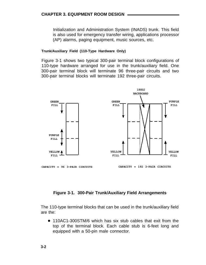
Initialization and Administration System (INADS) trunk. This fieldis also used for emergency transfer wiring, applications processor(AP) alarms, paging equipment, music sources, etc.
Trunk/Auxiliary Field (110-Type Hardware Only)
Figure 3-1 shows two typical 300-pair terminal block configurations of110-type hardware arranged for use in the trunk/auxiliary field. One300-pair terminal block will terminate 96 three-pair circuits and two300-pair terminal blocks will terminate 192 three-pair circuits.
188D2BACKBOARD
GREENFILL
PURPLEFILL
YELLOWFILL
CAPACITY = 96 3-PAIR CIRCUITS
GREENFILL
YELLOWFILL
PURPLEFILL
YELLOWFILL
CAPACITY = 192 3-PAIR CIRCUITS
Figure 3-1. 300-Pair Trunk/Auxiliary Field Arrangements
The 110-type terminal blocks that can be used in the trunk/auxiliary fieldare the:
● 110AC1-300STM/6 which has six stub cables that exit from thetop of the terminal block. Each cable stub is 6-feet long andequipped with a 50-pin male connector.
3-2

Hardware Equipment Room Applications
●
●
110AC1-300STF/6 which has six stub cables that exit from thetop of the terminal block. Each cable stub is 6-feet long andequipped with a 50-pin female connector.
110PC1-300CT which has six stub cables that exit from the top ofthe terminal block. Each cable stub is 6-feet long and equippedwith a 50-pin female connector.
Figure 3-2 shows two typical 900-pair terminal block configurations of110-type hardware arranged for use in the trunk/auxiliary field. One900-pair terminal block will terminate 288 three-pair circuits and two900-pair terminal blocks will terminate 576 three-pair circuits.
188C2BACKBOARD
GREEN PURPLEFILLFILL
PURPLEFILL
YELLOWFILL
YELLOWFILL
CAPACITY = 288 3-PAIR CIRCUITS
GREENFILL
YELLOWFILL
CAPACITY = 576 3-PAIR CIRCUITS
Figure 3-2. 900-Pair Trunk/Auxiliary Field Arrangements
The 900-pair 110P-type terminal block recommended for thetrunk/auxiliary field is the:
● 110PC1-900CB which is equipped with 36 female 50-pinconnectors. The connectors are mounted at the bottom of theterminal block. This allows for easy cable routing to the floorand/or the cable slack manager as required.
3-3

CHAPTER 3. EQUIPMENT ROOM DESIGN
● 110PC1-900CT which is equipped with 36 female 50-pinconnectors. The connectors are mounted at the top of theterminal block. This can be used if cable routing from the top isdesirable.
Distribution Field
The distribution field contains four distinct cross-connect areas:
● The purple field (port field) terminates 25-pair cables from theswitch. Each line circuit pack connects to one 66-type connectingblock or to one 25-pair row of the 110-type terminal block. One25-pair cable is required for each line circuit pack.
Note: This is the case except for the 16 port analog linecircuit pack and the MET line circuit pack. The 16-portanalog line circuit pack requires an adapter cable to connectfrom one connector on the switch to two 25-pair connectorson a 66-type connecting block/110-type terminal block. TwoMET line circuit packs require a concentrator cable toconnect from two connectors on the switch to one 25-pairconnector on a 66-type connecting block/110-type terminalblock.
●
●
●
The yellow field (auxiliary field) terminates all 25-pair cables fromthe auxiliary cabinet and the AP. The yellow field is located in thelower right-hand corner of the distribution field.
The white field (station field) terminates the station wiring. Thewhite field indicates 3-pair station circuits (eight circuits per25-pair cable) that are routed through a satellite closet.
The blue field (station field) also terminates station wiring. Theblue field indicates 3- and/or 4-pair station circuits (eight or sixcircuits, respectively, per 25-pair cable). The fourth pair, of the4-pair station circuit provides adjunct power from thecross-connect field on an as-needed basis to terminals within 250feet (wire length) of the cross-connect field.
3-4

Hardware Equipment Room Applications
Distribution Field (110-Type Hardware Only)
Figure 3-3 shows a typical 300-pair terminal block configuration of110-type hardware arranged for use in the distribution field. One300-pair terminal block will terminate 192 three-pair port circuits (purplefield), and either 192 three-pair station circuits (white or blue field) or144 four-pair station circuits (blue field).
188D2BACKBOARD
FILL
BLUE OR WHITE PURPLE
CAPACITY WHITE FIELD = 192 3-PAIR CIRCUITSCAPACITY BLUE FIELD = 144 4-PAIR CIRCUITS
OR 192 3-PAIR CIRCUITSCAPACITY PURPLE FIELD = 192 3-PAIR CIRCUITS
Figure 3-3. Distribution Field Arrangement of 110-TypeHardware—Four 300-Pair Terminal Blocks
Figure 3-4 shows a typical 300-pair terminal block configuration of110-type hardware arranged for use in the distribution field. Thisconfiguration will terminate 384 three-pair port circuits (purple field),
3-5

CHAPTER 3. EQUIPMENT ROOM DESIGN
and either 384 three-pair station circuits (white or blue field) or 288four-pair station circuits (blue field).
188D2BACKBOARD
188D2BACKBOARD
FILL
BLUE OR WHITE PURPLE BLUE OR WHITE
CAPACITY WHITE FIELD = CAPACITY BLUE FILED =
CAPACITY PURPLE FIELD =
384 3-PAIR CIRCUITS288 4-PAIR CIRCUITS OR384 3-PAIR CIRCUITS384 3-PAIR CIRCUITS
Figure 3-4. Distribution Field Arrangement of 110-TypeHardware—Eight 300-Pair Terminal Blocks
Figure 3-5 shows a typical 900-pair terminal block configuration of110-type hardware arranged for use in the distribution field. Thisconfiguration will terminate 576 three-pair port circuits (purple field),and either 576 three-pair station circuits (white or blue field) or 432four-pair station circuits (blue field).
3-6

Hardware Equipment Room Applications
188C2BACKBOARD
FILL
BLUE OR WHITE PURPLE
CAPACITY WHITE FIELD =CAPACITY BLUE FIELD =
576 3-PAIR CIRCUITS432 4-PAIR CIRCUITS OR576 3-PAIR CIRCUITS576 3-PAIR CIRCUITSCAPACITY PURPLE FIELD =
Figure 3-5. Distribution Field Arrangement of 110-TypeHardware—Four 900-Pair Terminal Blocks
Figure 3-6 shows a typical 900-pair terminal block configuration of110-type hardware arranged for use in the distribution field. Thisconfiguration will terminate 1152 three-pair port circuits (purple field),and either 1152 three-pair station circuits (white or blue field) or 864four-pair station circuits (blue field).
3-7

CHAPTER 3. EQUIPMENT ROOM DESIGN
188C2 188C2BACKBOARD BACKBOARD
FILL
BLUE OR WHITE PURPLE BLUE OR WHITE
CAPACITY WHITE FIELD = 1152 3-PAIR CIRCUITS
CAPACITY BLUE FIELD = 864 4-PAIR CIRCUITS OR1152 3-PAIR CIRCUITS
CAPACITY PURPLE FIELD = 1152 3-PAIR CIRCUITS
Figure 3-6. Distribution Field Arrangement of 110-TypeHardware—Eight 900-Pair Terminal Blocks
The following 110-type terminal blocks (Table 3-A) can be used in thedistribution field.
a.
b.
The 110AC1-300STM/6 is a factory assembled 300-pair terminalblock. It is equipped with twelve, 6-foot long, 25-pair cable stubs.Each cable stub exits from the top of the block, and is equipped witha 50-pin male miniature ribbon connector.
The 110AC1-300STF/6 is a factory assembled 300-pair terminalblock. It is equipped with twelve, 6-foot long, 25-pair cable stubs.Each cable stub exits from the top of the block, and is equipped witha 50-pin female miniature ribbon connector.
3-8

Hardware Equipment Room Applications
c.
d.
e.
f .
The 110AB1-100FT is a 100-pair terminal block (110AW1-100) foruse when the wiring is to be field terminated. It provides terminationspace for twenty-four 4-pair circuits.
The 110AB1-300FT is a 300-pair terminal block (110AW1-100) foruse when the wiring is to be field terminated. It provides terminationspace for seventy-two 4-pair circuits.
The 110AC1-100FT is a 100-pair terminal block (110AW1-100) foruse when the wiring is to be field terminated. It provides terminationspace for thirty-two 3-pair circuits.
The 110AC1-300FT is a 300-pair terminal block (110AW1-100) foruse when the wiring is to be field terminated. It provides terminationspace for ninety-six 3-pair circuits.
Table 3-A. Distribution Field—110A-Type Terminal Blocks
3-Pair Port Field 4-Pair Station Field 3-Pair Station Field(Purple) (Blue) (Blue or White)
110AC1-300STM/6 110AB1-100FT 110AC1-100FT110AC1-300STF/6 110AB1-300FT 110AC1-300FT
110AC1-300STM/6110AC1-300STF/6
The following 300-pair 110-type terminal blocks (Table 3-B) can be usedin the distribution field.
a.
b.
c .
The 110PC1-300CT is a factory assembled 300-pair terminal block.It is equipped with twelve female 50-pin miniature ribbon connectorsthat are mounted at the top of the block. The terminal block providestermination space for ninety-six 3-pair circuits.
The 110PB1-300CT is a factory assembled 300-pair terminal block.It is equipped with twelve female 50-pin miniature ribbon connectorsthat are mounted at the top of the block. The terminal block providestermination space for seventy-two 4-pair circuits.
The 110PB1-300FT is a 300-pair terminal block (110DW1-100) foruse when the wiring is to be field terminated. It provides terminationspace for seventy-two 4-pair circuits.
3-9

CHAPTER 3. EQUIPMENT ROOM DESIGN
d . The 110PC1-300FT is a 300-pair terminal block (110DW1-100) foruse when the wiring is to be field terminated. It provides terminationspace for ninety-six 3-pair circuits.
Table 3-B. Distribution Field—300-Pair 110P-Type Terminal Blocks
3-Pair Port Field 4-Pair Station Field 3-Pair Station Field(Purple) (Blue) (Blue or White)
110PC1-300CT 110PB1-300CT 110PC1-300CT110PB1-300FT 110PC1-300FT
The following 900-pair 110-type terminal blocks (Table 3-C) can beused in the distribution field.
a.
b.
c.
d.
e.
f .
The 110PC1-900CT is a factory assembled 900-pair terminal block.It is equipped with thirty-six female 50-pin miniature ribbonconnectors that are mounted at the top of the block. The terminalblock provides termination space for 576 3-pair circuits.
The 110PC1-900CB is a factory assembled 900-pair terminal block.It is equipped with thirty-six female 50-pin miniature ribbonconnectors that are mounted at the bottom of the block. Theterminal block provides termination space for 576 3-pair circuits.
The 110PB1-900CT is a factory assembled 900-pair terminal block.It is equipped with thirty-six female 50-pin miniature ribbonconnectors that are mounted at the top of the block. The terminalblock provides termination space for 432 4-pair circuits.
The 110PB1-900CB is a factory assembled 900-pair terminal block.It is equipped with thirty-six female 50-pin miniature ribbonconnectors that are mounted at the bottom of the block. Theterminal block provides termination space for 432 4-pair circuits.
The 110PB1-900FT is a 900-pair terminal block for use when thewiring is to be field terminated. It provides termination space for 4324-pair circuits.
The 110PC1-900FT is a 900-pair terminal block for use when thewiring is to be field terminated. It provides termination space for 5763-pair circuits.
3-10

Hardware Equipment Room Applications
Table 3-C. Distribution Field—900-Pair 110P-Type Terminal Blocks
3-Pair Port Field 4-Pair Station Field 3-Pair Station Field(Purple) (Blue) (Blue or White)
110PC1-900CB 110PB1-900CB 110PC1-900CB110PC1-900CT 110PB1-900CT 110PC1-900CT
110PB1-900FT 110PC1-900FT
Distribution Field (66-Type Hardware Only)
Figure 3-7 shows a typical cross-connect field using 66-type hardware.It is possible that only a few 66-type connecting blocks will be requiredin the trunk/auxiliary field for the green and yellow fields. For thisreason, if 157B connecting blocks mounted on a purple 183-type or166-type backboard is used as the trunk/auxiliary field, then some ofthe extra connecting blocks in the purple field can be used as the greenand yellow fields to save ordering extra backboards and connectingblocks. When this is done, the green and yellow fields should be clearlyidentified to avoid confusion. When white backboards are required forcross-connections with a satellite closet, they must be ordered from anoutside vendor. If a blue backboard is used for these cross-connections,then the part of the blue field that is functionally used as the white field,should be clearly identified.
3-11

CHAPTER 3. EQUIPMENT ROOM DESIGN
TRUNK/AUXILIARYFIELD
187B1BACKBOARDS
STATIONDISTRIBUTIONFIELD
PORTDISTRIBUTIONFIELD
Figure 3-7. Typical Cross-Connect Field Arrangement Using 66-Type Hardware
The 66-type connecting blocks can be mounted directly onto the wallwithout using colored backboards. If this is the case, all of thecross-connect field functional colors should be identified on the wall.
3-12

General
Typical System Equipment Room Floor Plans
Typical System Equipment Room Floor Plans
The equipment room floor plan must be provided by the FSO for firmquote price lists. For all other quotes, the equipment room floor plans
●
●
●
●
must be provided by the PSC. Factors that influence the design are:
Size and layout of the equipment room
Number of equipment cabinets
Location of AC receptacles
Size of the switch.
Typical Floor Plans
Figure 3-8 is a typical floor plan for a 2-carrier System 75 or a 2-cabinetSystem 75 XE. Figure 3-9 is a typical floor plan for a 5-carrier System 75or a 3- or 4-cabinet System 75 XE. The maximum capacity for a 2-carriercabinet is 200 stations and the maximum capacity for a 5-carrier cabinetis 800 stations.
3-13

CHAPTER 3. EQUIPMENT ROOM DESIGN
WALL NOTE 1
TRUNK/AUXILIARYFIELD
CROSS-CONNECT FIELD
CABLE SLACKMANAGER
(OPTIONAL)NOTE 3
TABLE
PRINTER(OPTIONAL)
SYSTEMACCESSTERMINAL
(SAT)
SYSTEMCABINET
(FRONT)
NOTE 2
32 INCHES
CHAIR
NOTES:1.
2.
3.
THE AC POWER RECEPTACLE MUST NOT BE UNDER SWITCH CONTROL AND MUST NOT BE SHARED WITH OTHEREQUIPMENT. THE AC POWER RECEPTACLE SHOULD BE LOCATED OUTSIDE THE CROSS-CONNECT FIELD AREA.ALSO, ANY CONDUIT SERVING THE OUTLET CANNOT RUN THROUGH OR BELOW THE AREA WHERE THECONNECTOR MODULES ARE TO BE MOUNTED.ALLOW AT LEAST 36 INCHES OF SPACE IN FRONT AND 6 INCHES ON THE RIGHTOF THE CABINETTO PERMIT THE DOOR TO SWING OPEN.CABINET IS LOCATED ALONGSIDE THE CROSS-CONNECT FIELD WHEN CABLE SLACK MANAGER IS NOTUSED.
Figure 3-8. Typical 2-Carrier Cabinet System 75 or 2-CabinetSystem 75 XE Floor Plan
3-14

Typical System Equipment Room Floor Plans
3-15

CHAPTER 3. EQUIPMENT ROOM DESIGN
Typical Cross-Connect Field Using 110-Type Hardware
The cross-connect field is located directly behind the switch cabinet.Figure 3-10 shows a typical cross-connect field installation using110A-type terminal blocks. Figure 3-11 shows a typical cross-connectfield installation using 300-pair 110P-type terminal blocks, and Figure3-12 shows a typical cross-connect field using 900-pair 110P-typeterminal blocks.
3-16

Typical System Equipment Room Floor Plans
D RING
STATIONCABLES
STATIONCABLES
STATIONCABLES
TRUNK/AUXILIARYFIELD STATION
CABLESPORT
DISTRIBUTIONFIELD
STATIONDISTRIBUTION
FIELD
Z114ACABLE SLACKMANAGER
SWITCHCABINET
Z113A CABLESLACK MANAGER
25-PAIR CABLETO SWITCHCABINET
Figure 3-10. Typical Cross-Connect Field lnstaIlation—110A-TypeTerminal Blocks (Approximately 576 4-Pair or 768 3-Pair Station Capacity Illustrated)
3-17

CHAPTER 3. EQUIPMENT ROOM DESIGN
D RING
STATIONCABLES
TRUNK/AUXILIARYFIELD
PORTDISTRIBUTION
FIELD STATIONDISTRIBUTION
FIELD
Z114ACABLE SLACKMANAGER
SWITCHCABINET
Z113A CABLESLACK MANAGER
25-PAIR CABLETO SWITCHCABINET
Figure 3-11. Typical Cross-Connect Field Installation—300-Pair110P-Type Terminal Blocks (Approximately 288 4-Pairor 384 3-Pair Station Capacity Illustrated)
3-18

Typical System Equipment Room Floor Plans
TRUNK/AUXILIARYFIELD
D RING PORT DISTRIBUTIONFIELD
STATION DISTRIBUTIONFIELD
STATIONCABLES
Z114ACABLE SLACKMANAGER
SWITCHCABINET
Z113A CABLESLACK MANAGER
25-PAIR CABLETO SWITCHCABINET
Figure 3-12. Typical Cross-Connect Field lnstallation—900-Pair110P-Type Terminal Blocks (Approximately 432 4-Pairor 576 3-Pair Station Capacity Illustrated)
3-19

CHAPTER 3. EQUIPMENT ROOM DESIGN
Typical Cross-Connect Field Using 66-Type Hardware
Figure 3-13 shows a typical cross-connect field installation using66-type connecting blocks.
D RING
STATIONCABLES
STATIONCABLES
STATIONCABLESTRUNK/
AUXILIARYFIELD
STATIONCABLESPORT
DISTRIBUTIONFIELD STATION
DISTRIBUTIONFIELD
Z114ACABLE SLACKMANAGER
SWITCHCABINET
Z113A CABLESLACK MANAGER
25-PAIR CABLETO SWITCHCABINET
Figure 3-13. Typical Cross-Connect Field Installation using 66-TypeConnecting Blocks
Wall Space Requirements
Approximately 8 inches of horizontal wall space is required for eachcolumn of sneak fuse panels. Horizontal wall space must also beprovided for emergency transfer units.
3-20

Typical System Equipment Room Floor Plans
Wall Space Requirements for 110-Type Hardware
The trunk/auxiliary field and the distribution field are mounted on thesame wall. Each 110P-type terminal block is 8-1/2 inches wide. Verticalpatch cord troughs are 5-5/16 inches wide and horizontal patch cordtroughs are 23 inches wide.
Each 110A-type terminal block is 10-13/16 inches wide; however, nohorizontal patch cord troughs are used and the blocks are shorter than110P-type terminal blocks. This allows the 110A-type terminal blocks tobe stacked. Therefore, the 110A-type hardware requires less spacethan the 110P-type hardware on a per-station basis.
Wall Space Requirements for 66-Type Hardware
The trunk/auxiliary field and the distribution field are mounted on thesame wall.
If the 66-type connecting blocks are being mounted directly on a wall,the space requirements of a 183-type backboard should be used tofigure the amount of wall space required for the connecting blocks. Thismethod allows enough space between the connecting blocks for jumperwires and cable connections. The 183A-type backboard mounts four66-type connecting blocks and is 8-1/2 inches wide and 20 inches tall.The 183B-type backboard mounts eight 66-type connecting blocks, andis 17 inches wide and 20 inches tall.
When multiple mountings are required, each 166-type mounting is 17inches wide and 20 inches tall, and each 154A-type mounting is 8-1/2inches wide and 20 inches tall.
The 187B1 backboard, equipped with pegs, is 17 inches wide and 6-1/2inches tall.
Equipment Requirements
Cable Slack Manager Requirements
A cable slack manager is 32 inches wide. The quantity of cable slackmanagers required is determined by dividing the total length of thecross-connect field (in inches) by 32. A partial number of .4 or lessshould be rounded down, and a partial number of .5 or more should be
3-21

CHAPTER 3. EQUIPMENT ROOM DESIGN
rounded up (for example: 2.4 = 2 cable slack managers and 2.5 = 3cable slack managers required).
110-Type Hardware and Patch Cord Requirements
Table 3-D lists the amount of 110-type hardware required to provide 1-,2-, 3-, or 4-pair distribution for the station wiring. The 110-type terminalblocks are available in various sizes and the number of stationsconnected to each block depends on the number of pairs that are runper station.
Table 3-D. 110-Type Hardware Requirements
Station WiringAvailable
Block Pairs 1-PairWiring*
2-PairWiring*
3-PairWiring
4-PairWiring
75 75 36 24 18100 100 48 32 24300 300 144 96 72900 900 432 288 216
* 1- and 2-pair wiring is only possible for analog telephones thatare cross-connected using 110A-type hardware.
3-22

Typical System Equipment Room Floor Plans
Table 3-E shows an algorithm for patch cord requirements based on theline capacity of the switch.
Table 3-E. 110 Patch Cord Requirements
Patch Cord Percent of LineLine Size Length Size Required
2 Feet 10.0%3 Feet 16.5%4 Feet 29.3%
0-216 5 Feet 26.0%6 Feet 18.2%7 Feet 0%8 Feet 0%9 Feet 0%2 Feet 5.5%3 Feet 15.5%4 Feet 29.3%
216-648 5 Feet 27.0%6 Feet 15.9%7 Feet 6.8%8 Feet 0%9 Feet 0%2 Feet 3.0%3 Feet 10.3%4 Feet 22.1%
648-800 5 Feet 25.7%6 Feet 22.5%7 Feet 8.5%8 Feet 5.7%9 Feet 2.2%
3-23

CHAPTER 3. EQUIPMENT ROOM DESIGN
66-Type Hardware Requirements
Table 3-F lists the amount of 66-type hardware required to provide 1-,2-, 3-, or 4-pair distribution for station wiring. Each 66-type connectingblock can terminate 25-pairs. The quantity of blocks required per switchdepends on the number of pairs required per station.
Table 3-F. 66-Type Hardware Requirements
66M 150Station Range
Blocks1-Pair 2-Pair 3-Pair 4-Pair
Required Wiring* Wiring* Wiring Wiring
1 1-24 1-12 1-8 1-62 25-48 13-24 9-16 7-123 59-72 25-36 17-24 13-184 73-96 37-48 25-32 19-245 97-120 49-60 33-40 25-306 121-144 61-72 41-48 31-367 145-168 73-84 48-56 37-428 169-192 85-96 57-64 43-489 193-216 97-108 65-72 49-5410 217-240 109-120 73-80 55-6011 241-264 121-132 81-88 61-6612 265-288 133-144 89-96 67-7213 289-312 145-156 97-104 73-7814 313-336 157-168 105-112 79-8415 337-360 169-180 113-120 85-9016 361-384 181-192 121-128 91-9617 385-408 193-204 129-136 97-10218 409-432 205-216 137-144 103-10819 433-456 217-228 145-152 109-11420 457-480 229-240 153-160 115-120
* 1- and 2-pair wiring is used only for analogtelephones.
3-24

Equipment Room Hardware And Cabling Installation
Equipment Room Hardware And CablingInstallation
Hardware Installation
The procedures, provided in this guide, for installing hardware arewritten so that one system technician can do the installation. Proceduresare provided for installing the following:
●
●
●
●
Cross-connect field
Cable slack managers
Labels for cross-connect field
Sneak fuse panels.
Installing the Cross-Connect Field
The preferred cross-connect field location is directly behind the switchcabinet.
Wall Mounting 110A-Type Terminal Blocks
The 110A-type hardware can be stacked in almost any arrangement atany height or location on the wall. One arrangement is shown in Figure3-10. The distance between the mounting screw holes on the terminalblocks is 10-13/16 inches. If a vertical patch cord trough is to used, thedistance between the mounting screw holes is 5-5/16 inches.
Wall Mounting 110P-Type Terminal Blocks
The first terminal block of the trunk/auxiliary field is aligned with the leftside of the switch cabinet (Figures 3-11 or 3-12). This arrangementallows for growth on the right side of the cross-connect field.
To install the cross-connect field, proceed as follows:
1. If 300-pair terminal blocks are to be installed, draw a level horizontalline on the wall 47-1/2 inches above the floor (Figure 3-14). If900-pair terminal blocks are to be mounted, draw a level horizontalline on the wall 23 inches above the floor (Figure 3-15).
3-25

CHAPTER 3. EQUIPMENT ROOM DESIGN
48 INCHES
AC POWERSTRIP
HORIZONTALLINE
80-1/2 INCHES
7-11/16 INCHES 5-5/16 INCHES7/8 INCH 47-1/2 INCHES
FLOOR LINE
Figure 3-14. Mounting 300-Pair 110P-Type Terminal Blocks(Approximately 288 4-Pair or 384 3-Pair StationCapacity Illustrated)
2.
3.
4.
5.
6.
To mount the first trunk/auxiliary field terminal block, partially installtwo 3/4-inch No. 12 wood screws, 7-11/16 inches apart on the leftside of the horizontal line on the wall
Slide the bottom terminal block feet onto the mounting screws andmark the upper mounting screw locations.
Remove the terminal block and partially install the upper mountingscrews.
Place the terminal block on the mounting screws and tighten thescrews.
If a vertical patch cord trough is to be installed, partially install thefirst screw for the patch cord trough, on the line, 7/8 inch to the right
3-26

Equipment Room Hardware And Cabling Installation
49 INCHES
HORIZONTALLINE
AC POWERSTRIP
96 INCHES
7-11/16 INCHES
HORIZONTALLINE
47-1/2 INCHES
23 INCHES7-11/16 INCHES 5-5/16 INCHES
7/8 INCH
FLOOR LINE
Figure 3-15. Mounting 900-Pair 110P-Type Terminal Blocks(Approximately 432 4-Pair or 576 3-Pair StationCapacity Illustrated)
of the previous screw. Partially install the second mounting screw5-5/16 inches to the right of the screw just installed. Repeat Steps3, 4, and 5.
If another trunk/auxiliary field terminal block is to be installed,7 .partially install the first screw for the terminal block, on the line, 7/8inch to the right of the previous screw. Partially install the second
3-27
CHAPTER 3. EQUIPMENT ROOM DESIGN
8.
9.
10.
11.
12.
mounting screw 7-11/16 inches to the right of the screw justinstalled. Repeat Steps 3, 4, and 5.
If a horizontal patch cord trough is to be installed, install it, on theline, between the trunk/auxiliary field and the distribution field.
To install the first distribution field terminal block, partially installtwo 3/4-inch, No. 12 wood screws, 7-11/16 inches apart on the line,to the right of the vertical patch cord trough. Repeat Steps 3, 4, and5.
If another distribution field terminal block is to be installed, partiallyinstall the first screw for the terminal block, on the line, 7/8 inch tothe right of the previous screw. Partially install the second mountingscrew 7-11/16 inches to right of the screw just installed. Repeatsteps 3, 4, and 5.
If a vertical patch cord trough is to be installed in the distributionfield, go to Step 6.
Repeat Steps 10 and 11 until all the terminal blocks and verticalpatch cord troughs in the distribution field have been installed.
Frame Mounting 110P-Type Terminal Blocks
The 900-pair 110P-type terminal blocks and the associated patch cordtroughs can also be mounted on a free-standing, floor-mounted 1110A2apparatus mounting frame (Figure 3-16). Each 1110A2 apparatusmounting frame provides the space to mount five terminal blocks/patchcord troughs on each side of the frame. A cable support structure,apparatus mounting 1110C1, mounts directly on top of the 1110A2apparatus mounting frame and provides support for all cables routed toand from the frame.
3-28

Equipment Room Hardware And Cabling Installation
NO. 1110C1APPARATUSMOUNTING
NO. 111OA2APPARATUSMOUNTING
88.50"
76.00"
43.50"
Figure 3-16. 1110A2 and 1110C1 Apparatus Mountings
3-29

CHAPTER 3. EQUIPMENT ROOM DESIGN
APPARATUS MOUNTING FRAME ORDERING INFORMATION
Code Number Description Comcode
1110A2 Apparatus Mounting Frame 104 032 495
1110C1 Cable Support Assembly 104 175 120
1110A1 End Dress Panel 104 176 268
2110A1 Top Dress Panel 104 176 276
2110B1 Bottom Dress Panel 104 176 284
Wall Mounting 66-Type Connecting Blocks
The first column of 66-type connecting blocks should be aligned withthe left side of the switch cabinet (Figure 3-7). This arrangement allowsfor orderly growth toward the right side of the cross-connect field.
The connectorized 66-type connecting blocks are factory wired forcable routing from the top so that the cable connector will align with theconnector on the connecting block. If cable routing from the bottom isdesired, then the connector on the connecting block must be removedand rotated 180 degrees. Then, the connector must be relocated in thepreviously unoccupied hole because the connecting block leads are notlong enough to reach the hole where the connector was previouslymounted. The VELCRO® cable retainer must also be relocated.
To install the cross-connect field, proceed as follows:
1. Draw a level horizontal line on the wall 12 inches above the floor(Figure 3-17).
* Registered trademark of VELCRO U.S.A. Inc..
3-30

Equipment Room Hardware And Cabling Installation
AC POWERSTRIP
78 1/2 INCHES
12 INCHES
FLOOR LINE
Figure 3-17. Cross-Connect Field Installation, 66-Type Connecting
2.
3.
4.
5.
Blocks
Place bottom of the first backboard/connecting block on the lineand align it vertically with the left side of the switch cabinet. Markthe mounting holes.
Remove the backboard/connecting block and drill holes in the wallfor 3/4-inch No. 12 wood screws.
Move the backboard/connecting block into place and fasten it tothe wall with 3/4-inch No. 12 wood screws.
The next backboard/connecting block can be mounted to the rightor above the one just installed, depending on space requirements.
3-31

CHAPTER 3. EQUIPMENT ROOM DESIGN
Repeat Steps 2, 3 and 4 until each backboard or connecting blockhas been installed.
Note: The 66-type connecting blocks should not be installed morethan 78-1/2 inches above the floor.
Installing Cable Slack Managers
To install the cable slack managers (Figure 2-17), proceed as follows:
1.
2.
3.
Place the Z113A cable slack manager against the wall under thecross-connect field (Figure 3-9), aligning the left side of the cableslack manager with the first terminal block of the trunk/auxiliaryfield.
Place the next cable slack manager beside the previously installedcable slack manager. Align the tabs and interlocks, and snap thecable slack managers together.
Repeat Step 2 until all cable slack managers are installed.
Note: Nine holes (¼-inch) are provided in a cable slack managerbase in the event earthquake mounting is required. Also, if a cableslack manager base is mounted on an uneven floor, shims may berequired to level it and insure proper fit of the covers. Holes areprovided in the sides of the base for bolting cable slack managerstogether. Bolts and shims must be obtained locally.
Labeling the Cross-Connect Field
Labeling 110-Type Terminal Blocks
Figure 3-18 shows the graphic symbols used (instead of words) onlabels for the switch, cross-connections, information outlets, and cablesfor the system. The labels are color-coded to identify system wiring asfollows:
●
●
●
Green—Leads to CO
Purple—Leads to switch ports
Yellow—Leads to auxiliary equipment and miscellaneous switchleads
3-32

Equipment Room Hardware And Cabling Installation
●
●
Blue—Leads to information outlets
White—Leads from the cross-connect field to the satellitelocations (3-pair).
Cabinet
Carrier
Slot
Information Outlet
Site/Satellite Closet
Tie Circuit
Floor Write Floor orBuilding Identification
Designations
1, 2, 3 . . . n
A, B, C, D, E
1 , 2 , 3 . . . 2 0
1 , 2 , 3 . . . 5 6 0
A, B, C, D, E, F
1, 2, 3 . . . n
on Label as RequiredBuilding for Easy Identification.
Figure 3-18. System Label Graphic Symbols and DesignationNomenclature
Each 110-type label is used to identify 2 rows on the 110-type terminalblock. The upper half of the label identifies the row above it and thelower half of the label identifies the row below it. The labels are insertedinto the clear plastic designation strips (Figure 3-19) that are furnishedwith the 110-type terminal blocks. After the label has been inserted intothe designation strip, the designation strip is snapped into place
3-33

CHAPTER 3. EQUIPMENT ROOM DESIGN
between the 110-type terminal block rows. Label code number 220A(comcode 103 970 000) contains all of the 110-type labels.
CLEAR PLASTICDESIGNATIONSTRIP
Figure 3-19. Clear Plastic Designation Strip
CO Trunk Labels (Green)
The labels shown in Figure 3-20 identify the network interface leads fortrunk circuits. On the top label, cable pairs are numbered consecutivelyfrom 1 to 300 (in groups of five). The bottom label is blank and must befilled in manually as required.
Label Code 221A—Green Labels (comcode 103 970 018)
Label code number 221A contains the following CO trunk labels:
●
●
(6) green trunk labels (Figure 3-20). The labels are numbered from1 to 300. Each label identifies 50 trunk pairs.
(4) unnumbered green labels (Figure 3-20). Each label identifies50 trunk pairs.
3-34

Equipment Room Hardware And Cabling Installation
1
26
5
30
GREEN
1 5 10 1540
2 04 5
2 5
5 026 3 0 35
● USAGE:IDENTIFIES NETWORK INTERFACE TRUNK PAIRS.
CODE NO:221A
●
GREEN
●
●
USAGE:CUSTOMER IDENTIFICATION OF NETWORKINTERFACE TRUNK PAIRS.
CODE NO:221A
Figure 3-20. CO Trunk Labels for 110-Type Terminal Blocks
Auxiliary Labels (Yellow)
AUXILIARY PORT AND CIRCUIT LABELS
The labels shown in Figure 3-21 identify auxiliary port and circuitappearances at the cross-connect field. The labels must be filled inmanually.
3-35

CHAPTER 3. EQUIPMENT ROOM DESIGN
1
YELLOW
●
●
USAGE:IDENTIFIES 3-PAIR AUXILIARYCIRCUITS 1 THROUGH 8CODE NO:222A
1
YELLOW
●
●
USAGE:IDENTIFIES SSI PORTS 1 THROUGH 6FORM AN AP.
CODE NO:222A
Figure 3-21. Auxiliary Port and Circuit Appearance Labels for 110-Type Terminal Blocks
AUXILIARY CIRCUIT AND CONTROL CARRIER OUTPUTS (AUXILIARY)LABELS
The labels shown in Figures 3-22 and 3-23 identify auxiliary circuitappearances and the control carrier AUXILIARY connector outputs forSystem 75 and 75 XE, respectively. The top half of the labels identify
3-36

Equipment Room Hardware And Cabling Installation
auxiliary circuit appearances and must be filled in manually. The bottomhalf of the labels identify the control carrier AUXILIARY connectoroutputs.
●
●
USAGE:IDENTIFIES CONTROL CARRIER OUTPUTS (AUXILIARY) ANDAUXILIARY CIRCUITS
CODE NO:222A
Figure 3-22. Auxiliary Circuit and Control Carrier Outputs(AUXILIARY) Labels for 110-Type TerminalBlocks—System 75
3-37

Equipment Room Hardware And Cabling Installation
●
●
USAGE:IDENTIFIES CONTROL CARRIER OUTPUTS (AUXILIARY) ANDAUXILIARY CIRCUITS
CODE NO:222A
Figure 3-23. Auxiliary Circuit and Control Carrier Outputs(AUXILIARY) Labels for 110-Type TerminalBlocks—System 75 XE
Z1A EMERGENCY TRANSFER UNIT AND CONTROL CARRIER OUTPUTS(AUXILIARY) LABELS
The labels shown in Figures 3-24 and 3-25 identify the leads andconnection point for –48 volt dc power to the Z1A emergency transferunit and the control carrier AUXILIARY connector outputs for System 75and 75 XE, respectively. The top half of the labels identify the Z1Aemergency transfer unit and the bottom half of the labels identify thecontrol carrier AUXILIARY connector outputs. The control carrierAUXILIARY connector outputs are the same as described for theauxiliary circuit and control carrier outputs labels.
3-38

Equipment Room Hardware And Cabling Installation
●
●
USAGE:IDENTIFIES CONTROL CARRIER OUTPUTS (AUXILIARY) ANDZ1A EMERGENCY TRANSFER UNIT CIRCUITS
CODE NO:222A
Figure 3-24. Z1A Emergency Transfer Unit and Control Carrier Out-puts (AUXILIARY) Label for 110-Type TerminalBlocks—System 75
3-39

CHAPTER 3. EQUIPMENT ROOM DESIGN
●
●
USAGE:IDENTIFIES CONTROL CARRIER OUTPUTS (AUXILIARY) ANDZ1A EMERGENCY TRANSFER UNIT CIRCUITS
CODE NO:222A
Figure 3-25. Z1A Emergency Transfer Unit and Control Carrier Out-puts (AUXILIARY) Label for 110-Type TerminalBlocks—System 75 XE
574-5 POWER TRANSFER UNIT AND CONTROL CARRIER OUTPUTS(AUXILIARY) LABELS
The labels shown in Figures 3-26 and 3-27 identify the leads to the574-5 power transfer unit and the control carrier AUXILIARY connectoroutputs for System 75 and 75 XE, respectively. The top half of the labelsidentify the 574-5 power transfer unit and the bottom half of the labelsidentify the control carrier AUXILIARY connector outputs. The controlcarrier AUXILIARY connector outputs are the same as described for theauxiliary circuit and control carrier outputs labels.
3-40

Equipment Room Hardware And Cabling Installation
●
●
USAGE:IDENTIFIES CONTROL CARRIER OUTPUTS (AUXILIARY)AND 574-5 EMERGENCY TRANSFER UNIT CIRCUITS
CODE NO:222A
Figure 3-26. 574-5 Power Transfer Unit and Control Carrier Outputs(AUXILIARY) Labels for 110-Type TerminalBlock—System 75
3-41

CHAPTER 3. EQUIPMENT ROOM DESIGN
●
●
USAGE:IDENTIFIES CONTROL CARRIER OUTPUTS (AUXILIARY)AND 574-5 EMERGENCY TRANSFER UNIT CIRCUITS
CODE NO:222A
Figure 3-27. 574-5 Power Transfer Unit and Control Carrier Outputs(AUXILIARY) Labels for 110-Type TerminalBlock—System 75 XE
Z1A EMERGENCY TRANSFER UNIT LABELS
The label shown in Figure 3-28 identifies the emergency transfer leadsand the -48 volt dc power connection for the Z1A emergency transferunit.
3-42

Equipment Room Hardware And Cabling Installation
● CODE NO:222A
Figure 3-28. Z1A Emergency Transfer Unit Label
574-5 POWER TRANSFER UNIT LABEL
Both sections of the label shown in Figure 3-29 identify leads to the574-5 power transfer unit.
● CODE:222A
Figure 3-29. 574-5 Power Transfer Unit Label
3-43

CHAPTER 3. EQUIPMENT ROOM DESIGN
BLANK AUXILIARY LABEL
The blank label shown in Figure 3-30 identifies auxiliary equipment andmust be filled in manually.
●
●
USAGE:CUSTOM IDENTIFICATION OF AUXILIARY EQUIPMENT
CODE NO:222A
Figure 3-30. Blank Auxiliary Labels
Label Code 222A—Yellow Labels (comcode 103 970 026)
Lable code 222A contains the following labels:
●
●
●
●
●
connector labels (Figures 3-22 or 3-23)
connector labels (Figures 3-24 or 3-25)
(4) AP SSI port labels (Figure 3-20)
(4) 3-pair auxiliary circuit labels (Figure 3-21)
(2) unnumbered auxiliary circuit and control carrier AUXILIARY
(2) Z1A emergency transfer unit and control carrier AUXILIARY
(2) 574-5 power transfer unit and control carrier AUXILIARY
(2) 574-5 power transfer unit labels (Figure 3-29)
(6) blank labels (Figure 3-30).
connector labels (Figures 3-26 or 3-27)
●
●
●
(2) Z1A emergency transfer unit labels (Figure 3-28)
3-44

Equipment Room Hardware And Cabling Installation
Station Labels (White and Blue)
3-PAIR WHITE STATION LABELS
The white labels shown in Figure 3-31 identify 3-pair station appearancesat the cross-connect field that connect to a satellite location. The toplabels are grouped and numbered in sequence, A 1 to A 160 through F1 to F 160 to correspond to the satellite locations. The bottom labelsmust be filled in manually. These labels are installed starting with thefirst terminal block in the white field.
3-45

CHAPTER 3. EQUIPMENT ROOM DESIGN
A 1
A 9
WHITE
A 1 A 2 A 3 A 4 A 5 A 6 A 7 A 8
A 9 A 10 A 11 A 12 A 13 A 14 A 15 A 16
●
●
USAGE:IDENTIFIES 3-PAIR CIRCUIT APPEARANCESTHAT CONNECT TO A SATELLITE LOCATION.
CODE NO:223A
WHITE
●
●
USAGE:CUSTOM IDENTIFICATION OF 3-PAIR CIRCUITAPPEARANCES THAT CONNECT TO ASATELLITE LOCATION.
CODE NO:223A
Figure 3-31. 3-Pair White Station Wiring (Equipment Room) Labels
3-46

Equipment Room Hardware And Cabling Installation
Label Code 223A—White Labels (comcode 103 970 034)
Label code 223A contains the following labels:
●
●
(60) white labels that identify 3-pair circuits from the equipmentroom to the satellite closet (Figure 3-31). Each label identifies 16three-pair station circuits. There are labels for satellite closetsnumbered A through F, and each satellite closet has stationcircuits numbered 1 through 160.
(20) unnumbered white labels (Figure 3-31) that identify 3-pairstation circuits from the satellite closet. Each label identifiestwelve 3-pair station circuits.
3-PAIR BLUE STATION LABELS
The labels shown in Figure 3-32 identify 3-pair blue station appearancesat the cross-connect field. The top labels are numbered and should beinstalled in sequence (1 to 560) starting with the first terminal block inthe blue field. The bottom label must be filled in manually.
3-47
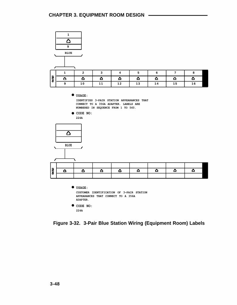
CHAPTER 3. EQUIPMENT ROOM DESIGN
1
9
BLUE
1 2 3 4 5 6 7 8
9 1 0 1 1 1 2 1 3 1 4 1 5 1 6
●
●
USAGE:IDENTIFIES 3-PAIR STATION APPEARANCES THATCONNECT TO A 356A ADAPTER. LABELS ARENUMBERED IN SEQUENCE FROM 1 TO 560.
CODE NO:224A
BLUE
●
●
USAGE:CUSTOMER IDENTIFICATION OF 3-PAIR STATIONAPPEARANCES THAT CONNECT TO A 356AADAPTER.
CODE NO:224A
Figure 3-32. 3-Pair Blue Station Wiring (Equipment Room) Labels
3-48

Equipment Room Hardware And Cabling Installation
Label Code 224A—Blue Labels (comcode 103 970 042)
Label code 224A contains the following labels:
●
●
●
●
●
●
(35) blue labels (Figure 3-32) that identify 3-pair station circuitsfrom the equipment room. Each label identifies sixteen 3-pairstation circuits. The labels are numbered sequentially from 1 to560.
(40) blue labels (Figure 3-33) that identify 4-pair station circuitsfrom the equipment room. Each label identifies twelve 4-pairstation circuits. The labels are numbered sequentially from 1 to480.
(102) blue labels (Figure 3-33) that identify 4-pair station circuitsfrom the satellite closet. Each label identifies twelve 4-pair stationcircuits. There are labels for satellite closets numbered A throughF, and each satellite closet has station circuits numbered 1through 204.
Unnumbered blue labels (Figure 3-32) that identify 3-Pair stationcircuits from the equipment room. Each label identifies sixteen3-pair station circuits.
Unnumbered blue labels (Figure 3-33) that identify 4-pair stationcircuits from the equipment room. Each label identifies twelve4-pair station circuits.
(28) unnumbered blue labels (Figure 3-34) that identify 4-pairstation circuits from the satellite closet. Each label identifiestwelve 4-pair station circuits.
4-PAIR BLUE STATION LABELS
The labels shown in Figure 3-33 identify 4-pair station appearances atthe cross-connect field. The top labels are numbered and installed insequence (1 to 480) starting with the first terminal block in the blue field.The bottom label must be filled in manually. The labels shown in Figure3-34 identify 4-pair station circuits from the satellite closet. The toplabels are grouped and numbered in sequence A 1 to A 204 through F1 to F 204 to correspond to the satellite locations and informationoutlets.
3-49

CHAPTER 3. EQUIPMENT ROOM DESIGN
BLUE
●
●
USAGE:IDENTIFIES 4-PAIR STATION APPEARANCES.LABELS ARE NUMBERED IN SEQUENCE FROM1 TO 480.
CODE NO:224A
BLUE
●
●
USAGE:CUSTOMER IDENTIFICATION OF 4-PAIR STATIONAPPEARANCES.
CODE NO:224A
Figure 3-33. 4-Pair Blue Station Wiring (Equipment Room) Labels
3-50

Equipment Room Hardware And Cabling Installation
BLUE
●
●
USAGE:IDENTIFIES 4-PAIR STATION APPEARANCESAT THE SATELLITE LOCATION.
CODE NO:224A
BLUE
●
●
USAGE:CUSTOMER IDENTIFICATION OF 4-PAIR STATIONAPPEARANCES AT THE SATELLITE LOCATION.
CODE NO:224A
Figure 3-34. 4-Pair Blue Station Wiring (Satellite Closet) Labels
3-51

CHAPTER 3. EQUIPMENT ROOM DESIGN
Port Labels (Purple)
PORT LABELS
The labels shown in Figure 3-35 identify the equipped carrier slots (seeNote) in the switch cabinet. These labels are grouped together (bycarriers) starting with Carrier A. These labels are used for thetrunk/auxiliary field, and the distribution field. They are installed startingwith the first terminal block in either field. The top label is grouped andnumbered in sequence 1A1 to 1A10 and 1B1 to 1B20 through 1E1 to1E20 to correspond to the cabinet, carrier, and slot of the port circuitpack. The bottom label must be filled in manually. It is used to label theMET line circuit pack and the 16-port analog line circuit pack. Anexample of how to fill out the label for the MET line circuit pack is shownin Figure 3-36. An example of how to fill out the label for the 16-portanalog line circuit pack is shown in Figure 3-37. If WP-90929, List 1 or3 concentrator cables are used to connect trunk or tie trunk circuits tothe switch, then use the labels shown in Figure 3-38 and 3-39 for thesecircuits. Figure 3-40 shows an example of how to fill out a dual-purposeemergency transfer station label.
Note: Equipped carrier slots are identified on the CustomerService Order (CSO).
3-52

Equipment Room Hardware And Cabling Installation
PURPLE PURPLE
●
●
USAGE:IDENTIFIES CABINET, CARRIER, PORT CIRCUIT SLOTNUMBERS, AND EIGHT PORT CIRCUITS.
CODE NO:225A
PURPLE
●
●
USAGE:CUSTOM IDENTIFICATION OF CABINET, CARRIER, PORT CIRCUITSLOT NUMBERS, AND EIGHT PORT CIRCUITS.
CODE NO:225A
Figure 3-35. Port Labels
3-53

CHAPTER 3. EQUIPMENT ROOM DESIGN
PURPLE PURPLE
Figure 3-36. Example of Port Label for MET Line Circuit Pack
PURPLE
Figure 3-37. Example of Port Label for 16-Port Analog Line CircuitPack
3-54

Equipment Room Hardware And Cabling Installation
SYSTEM TRUNK AND TIE TRUNK PORT LABELS
WP-90929, List 1 or 3 concentrator cables can be used between theswitch cabinet and the 110-type terminal blocks. The label shown inFigure 3-38 identifies 3-pair trunk circuits from the switch cabinet. Thelabel shown in Figure 3-39 identifies 3-pair tie trunk circuits from theswitch cabinet.
●
●
USAGE:IDENTIFIES CO TRUNK CIRCUIT PORTS WHENWP-90929, LIST 1 CONCENTRATOR CABLE IS USED
CODE NO:225A
Figure 3-38. Switch Trunk Port Circuit Labels
3-55

CHAPTER 3. EQUIPMENT ROOM DESIGN
PURPLE
●
●
USAGE:IDENTIFIES TIE TRUNK CIRCUIT PORTS WHENWP-90929, LIST 3 CONCENTRATOR CABLE IS USEDCODE NO:225A
Figure 3-39. Switch Tie Trunk Port Circuit Labels
DUAL-PURPOSE EMERGENCY TRANSFER STATION LABELS
The label shown in Figure 3-40 identifies the telephone connections atthe cross-connect field for both normal use and emergency transferstations.
3-56

Equipment Room Hardware And Cabling Installation
PURPLE
● CODE NO:225A
Figure 3-40. Dual-Purpose Emergency Transfer Station Labels
Label Code 225A—Purple Labels (comcode 103 970 059)
Label code number 225A contains the following port labels:
●
●
●
●
(45) purple labels (Figure 3-35) that identify 3-pair port circuitsfrom the switch. The labels are numbered for the carriers at theswitch, A through E, and each carrier has slots numbered 1 to 20,except carrier A which is only 1 to 10. Each label identifies 163-pair circuits.
(10) unnumbered purple labels (Figure 3-35) that identify 3-pairport circuits from the switch. Each label identifies 16 3-paircircuits.
(3) purple labels that identify 3-pair system trunk port circuits fromthe switch when WP-90929, List 1 (Figure 3-40) concentratorcables are used.
(3) purple labels that identify 3-pair system tie trunk port circuitsfrom the switch when WP-90929, List 3 (Figure 3-39) concentratorcables are used.
3-57

CHAPTER 3. EQUIPMENT ROOM DESIGN
● (5) purple labels to identify connections to dual-purposeemergency transfer stations (Figure 3-40).
Labeling 66-Type Connecting Blocks
The cross-connect field is color-coded to identify system wiring asfollows:
●
●
●
●
●
Green—Leads to CO
Purple—Leads to switch ports
Yellow—Leads to auxiliary equipment and miscellaneous switchleads
Blue—Leads to information outlets
White—Leads from the cross-connect field to the satellitelocations (3-pair).
A permanent felt-tipped pen can be used to write the lead designationson the 66-type connecting blocks (Figure 3-41). Table 3-G shows thelead designations for the switch port appearances at the cross-connectfield, and Table 3-H shows the lead designations for the auxiliarycircuits. Any time these leads are cross-connected to another connectingblock they should also be labeled at that block.
3-58

Equipment Room Hardware And Cabling Installation
LEFT SIDEOF 66-TYPECONNECTINGBLOCK
Figure 3-41. Labeling 66-Type Connecting Blocks
3-59

CHAPTER 3. EQUIPMENT ROOM DESIGN
3-60

Equipment Room Hardware And Cabling Installation
3-61

CHAPTER 3. EQUIPMENT ROOM DESIGN
FieldTable 3-H. Auxiliary Lead Appearances at 66-Type Cross-Connect
66-Type System System Z1A
Conn 75 Auxiliary 75 XE Auxiliary Emerg
Block Connector Connector Xfr Unit
Term Outputs Outputs Outputs
0102
1M
0304
1m
0506
2M
0708
2m
0910
3M
TC
TK
TC
TK
1112
3m
1314 3W
15161718
Not Connected
19
TK
Not Connected
2021 GND
TK TK
22 -4823 GND24 -4825 GND26 -4827 GND28 -4829 GND30 -4831 GND32 -4833 GND34 -48
ST ST
TCEmergency
TransferRelayPower
1M
1m
2M LC
2m LC
3M TC
3m
3W LC
ST
TC
574-5Power
Xfr UnitOutputs
LC
LC
TC
TK
LC
ST
TC
GND LC LC-48
GND-48
GND-48 Emergency
GND Transfer-48 Relay
GND Power-48
GND-48
GND-48
TK
LC
ST
TC
TC
TK
LC
ST
TC
3-62

Equipment Room Hardware And Cabling Installation
Table 3-H. Auxiliary Lead Appearances at 66-Type Cross-ConnectField (Contd)
66-Type System System Z1A 574-5Conn 75 Auxiliary 75 XE Auxiliary Emerg PowerBlock Connector Connector Xfr Unit Xfr UnitTerm Outputs Outputs Outputs Outputs
3536 Not Connected TK TK
37 GND38 48
LC LC
39 GND40 ACC Power Not Connected ST ST
-4841 GND TC
COM142 -48 N0143 TK
NC244 NC145 Not Connected
Ext Alarm A COM246 Ext Alarm B
LCN02
47 Not Connected STCOM3
48 NC349 GRD50 INADS INADS PWR -48V
Installing Sneak Fuse Panels
The sneak fuse panel (Figure 2-18) must be installed as near aspossible to the network interface. To install the sneak fuse panel,proceed as follows:
1.
2.
3.
4.
Hold the panel against the mounting surface and mark the upperright and lower left mounting screw locations.
Drill pilot holes at the marked locations, and partially install the 3/4inch No. 12 screws.
Slide the sneak fuse panel onto the mounting screws and tightenthe screws.
Repeat the procedure for each sneak fuse panel.
3-63

CHAPTER 3. EQUIPMENT ROOM DESIGN
Cable Installation
Labels
The purple port Iabel shown in Figure 3-42 installed on both ends ofthe 25-pair cables that connect to the trunk/auxiliary field and/or thedistribution field. The blue/yellow building and floor labels are for cablesthat connect from the equipment room to a site/satellite location onanother floor or in another building. The yellow label is for auxiliarycircuits that connect to the trunk/auxiliary field or for SSI circuits thatconnect to an AP.
The blue/yellow label is for 25-pair cables that connect to site/satelliteclosets.
LABEL NAME RANGE SAMPLE LABEL
PORT CABLE 1A1-1A10, 1B1-1B20,1C1-1C20, 1D1-1D20,1E1-1E20
BUILDING
FLOOR
AUXILIARYCABLE
FIELD IDENTIFIED
FIELD IDENTIFIED
FIELD IDENTIFIED
PURPLE
BLUE/YELLOW
YELLOW
SITE ORSATELLITE
A-F AND/ORFIELD IDENTIFIED BLUE/YELLOW
Figure 3-42. Equipment Room Cabling Labels
3-64

Equipment Room Hardware And Cabling Installation
CABLE/CONNECTOR/BUILDING LABEL ORDERING INFORMATION
Description Qty. Per. Code Comcode
201A Labels 34 Sheets 103 969 994
Figure 3-43 shows the proper way to install a label on a 25-pair cableconnector (see Note).
Note: The label should be installed near the rear of the connectoras shown in Figure 3-43 so it will not be obscured by the switchcabinet connector retainers. Also, it can be installed on the skin ofthe cable near the connector.
1 A 2PURPLE
Figure 3-43. Installing Self-Stick Label on 25-Pair Cable Connector
3-65

CHAPTER 3. EQUIPMENT ROOM DESIGN
Routing Cable Guidelines
General
The following guidelines should be followed when installing theequipment room cabling. FoIlowing these guidelines will maximize useof the cable slack managers and make future cabling additions andchanges easier.
Figures 3-44 and 3-45 show typical cable routing from the switchcabinet to the top and bottom of the cross-connect field, respectively.
POWERCORD
➀
➁
CABLES RUN FROM SWITCH CABINET TO TRUNK/AUXILIARYFIELD.
CABLES RUN FROM SWITCH CABINET TO STATION DISTRIBUTIONFIELD.
Figure 3-44. Cable Routing From Switch Cabinet to Cross-Connect
BUILDINGCABLES
Field (Using Top Terminal Blocks)
3-66

CROSSS-CONNECT FIELD
POWERCORD
Equipment Room Hardware And Cabling Installation
TRUNK/AUXILIARY STATION DISTRIBUTION
BUILDINGCABLE SLACK CABLE SLACK CABLE SLACK CABLES
MANAGER MANAGER MANAGERNO. 1 NO. 2 NO. 3
SYSTEMCABINET
(FRONT)
➀ CABLES RUN FROM SWITCH CABINET TOTRUNK/AUXILIARY FIELD.
➁ CABLES RUN FROM SWITCH CABINET TOSTATION DISTRIBUTION FIELD.
Figure 3-45. Cable Routing From Switch Cabinet to Cross-ConnectField (Using Bottom Terminal Blocks)
Routing Cables Using 110-Type Terminal Blocks
Figures 3-46 and 3-47 show the cable routing pattern through the cableslack manager for a single cabinet installation using connectorized110-type terminal blocks with the connectors located at the top andbottom of the terminal blocks, respectively. Cables are routed throughthe cable slack manager in either the cabinet or wall troughs. Whenneeded, the two center troughs can be used.
Port cables are routed through the cabinet trough for parallel runs.Station cables should use the wall trough. After the cabinet and walltroughs are filled, use the center trough.
3-67

CHAPTER 3. EQUIPMENT ROOM DESIGN
CABLE CLAMP
SWITCHCABINET
CABLE SLACKMANAGER
CABINET TROUGH SPARE CENTERFOR PORT CABLES TROUGHS
Figure 3-46. Cable Routing Through Cable Slack Manager—Single-Cabinet Installation (Using Connectorized TopTerminal Blocks)
3-68

Equipment Room Hardware And Cabling Installation
CABLE CLAMP
CABLE SLACKMANAGER
SWITCHCABINET
CABINET TROUGH SPARE CENTERFOR PORT CABLES TROUGHS
Figure 3-47. Cable Routing Through Cable Slack Manager—Single-Cabinet Installation (Using Connectorized Bottom Ter-minal Blocks)
3-69
CHAPTER 3. EQUIPMENT ROOM DESIGN
Routing Cables Using 66-Type Connecting Blocks
Figures 3-48 and 3-49 show the cable routing pattern through the cableslack manager for a single cabinet installation with the cables routedfrom the top and bottom of the 66-type connecting blocks, respectively.Cables are routed through the cable slack manager in either the cabinetor wall troughs. When needed, the two center troughs can be used.
Port cables are routed through the cabinet trough for parallel runs.Station cables should use the wall trough. After the cabinet and walltroughs are filled, use the center trough.
3-70

Equipment Room Hardware And Cabling Installation
CABLE CLAMP
CABLE SLACKMANAGER
SWITCHCABINET
CABINET TROUGHFOR PORT CABLES
SPARE CENTERTROUGHS
Figure 3-48. Cable Routing Through Cable Slack Manager—Single-Cabinet Installation (Using 66-Type Connecting BlocksWith Cables Routed From Top of Cross-Connect Field)
3-71

CHAPTER 3. EQUIPMENT ROOM DESIGN
CABLE CLAMP
SWITCHCABINET
CABLE SLACKMANAGER
CABINET TROUGH SPARE CENTERFOR PORT CABLES TROUGHS
Figure 3-49. Cable Routing Through Cable Slack Manager—Single-Cabinet Installation (Using 66-Type Connecting BlocksWith Cables Routed From Bottom of Cross-ConnectField)
3-72

Equipment Room Hardware And Cabling Installation
Routing Cables From Cabinet to Cross-Connect Field
The following guidelines should be followed when routing cables fromthe cabinet to the cross-connect field.
●
●
●
When cable routing is to the top/bottom of the cross-connectfield, each port cable is connected at the cabinet and then routedalong the front trough of the cable slack manager to theconnecting/terminal block where the cable is to be terminated.
Enough slack must be left at the cabinet end of the cable to allowfor proper dressing of the cables (Figure 3-50).
Route the cable from the cabinet to the wall. Place the cablebeside one of the rows of columns in the cable slack manager(see Note).
Note: Retainers mounted on the columns keep the cablefrom protruding above the top of the base of the cable slackmanager.
●
●
●
●
Determine the length of the cable required to reach from the cableslack manager to the assigned connecting/terminal block.
The cable must be supported on the wall using D rings.
Cable slack is stored by coiling the cable around the columns inthe cable slack manager. The first run should always go acrossthe full length of the five columns in the cable slack manager.
Connect the cable to the assigned connecting/terminal block.
3-73

CHAPTER 3. EQUIPMENT ROOM DESIGN
CABLECLAMP
CABLE TIES(OPTIONAL)
CABLECLAMP
POWERCORD
Figure 3-50. Typical Port Cable Installation at Switch Cabinet
3-74

Equipment Room Hardware And Cabling Installation
Installing Control Carrier Outputs Cable
The control carrier AUXILIARY connector outputs include the following:
●
●
●
●
●
Alarm monitoring for the AP and auxiliary cabinet
(7) dc power (-48 volts) sources for emergency transfer units
(3) dc power (-48 volts) sources for remotely powering twoattendant consoles and one executive voice terminal adjunct (notprovided on System 75 XE)
The INADS trunk connection location.
For the System 75 XE, access to a relay contact is available toactuate a light, bell, or similar type customer-provided alarmdevice. The relay can be administered to make contact when amajor, minor or warning alarm condition occurs in the switch. Thecircuitry required for this feature must be provided by thecustomer. The device connected to the alarm leads must notexceed a rating of more than 100 volts at ¾ amps.
A 25-pair cable connects the control carrier AUXILIARY connector(Figures 3-51 and 3-52) to a 66-type connecting block/110-type terminalblock in the yellow field of the trunk/auxiliary field.
3-75

CHAPTER 3. EQUIPMENT ROOM DESIGN
CONTROL CARRIER (REAR VIEW)
Figure 3-51. Control Carrier Outputs (AUXILIARYConnector)—System 75
CONTROL CARRIER (REAR VIEW)
Figure 3-52. Control Carrier Outputs (AUXILIARYConnector)—System 75 XE
3-76

Equipment Room Hardware And Cabling Installation
Labeling Control Carrier Cable (Used With 110-Type Hardware)
Place the appropriate AUXILIARY connector label (Figure 3-30) on theassigned 110-type terminal block row. On the control carrier cable,place a yellow auxiliary label (Figures 3-42 and 3-43) on the connectorsat each end of the cable. Write the letters AUX on each label.
Labeling Control Carrier Cable (Used With 66-Type Hardware)
Write the lead designations for the AUXILIARY connector (Table 3-G) onthe 66-type connecting block. If cable labels are to be used, place ayellow auxiliary label (Figures 3-42 and 3-43) on the connectors at eachend of the cable. Write the AUX on each label. If cable labels are notavailable, use a magic marker to write AUX on the connectors at eachend of the cable.
Connecting Control Carrier Outputs Cable
Plug the connector cable in the AUXILIARY connector on the rear of thecontrol carrier. Route the connector cable through the cable slackmanager to the assigned 66-type connecting block/110-type terminalblock in the yellow field of the trunk/auxiliary field.
The output wiring connections for alarm monitoring, emergency powerfailure, accessory power, and the INADS trunk interface is contained inChapter 4 of this guide under the heading Miscellaneous WiringInstallation.
Installing Trunk Cables Between Network Interface, Sneak Fuse Panel, andSwitch Cabinet
The 1-pair CO trunks are installed by the local telephone company in thegreen field. Up to 24 pairs may be terminated on each 66-typeconnecting block or on each row of the 110-type terminal block. Tietrunks also appear in the green field with up to eight 3-pair trunksterminated on each 66-type connecting block or on each row of the110-type terminal block.
Selecting Concentrator Cables For Use With 110-Type Hardware
WP-90929, List 1 and 3 concentrator cables can be used to connect theswitch cabinet to the 110-type terminal blocks in the purple field. The
3-77

CHAPTER 3. EQUIPMENT ROOM DESIGN
1-pair patch cords/jumper wires are then run from the purple terminalblock rows to the green terminal block rows in order to establish thecorrect 3-pair modularity. Table 3-H shows switch port appearances atthe cross-connect field. Figures 3-53, 3-54, and 3-55 show the carrierconnectors on the rear of the switch that connect to the purple field.
CABINET
FANS
CONTROL CARRIER A
PORT CARRIER B
REAR VIEW
A10 A01
B20 B11 B10 B01
Figure 3-53. System 75, Slot Addresses for 2-Carrier Cabinet
3-78

Equipment Room Hardware And Cabling Installation
3-79

Equipment Room Hardware And Cabling Installation
3-80

Equipment Room Hardware And Cabling Installation
Selecting Concentrator Cables For Use With 66-Type Hardware
WP-90929, List 2 and 4 concentrator cables can be used to connect theswitch cabinet to the 66-type connecting blocks in the purple field.Jumper wires are then run from the connecting blocks in the purple fieldto the connecting blocks in the green field to establish the correct 3-pairmodularity for the 1- and 3-pair trunks. Table 3-H shows switch portappearances at the cross-connect field. Figures 3-53, 3-54, and 3-55show the carrier connectors on the rear of the switch that connect to thepurple field.
Connecting Trunk Pairs to the Switch Cabinet Using Concentrator Cables
Figure 3-56 shows trunk pairs connected to the switch cabinet withconcentrator cables. To install the cables, proceed as follows:
1.
2.
3.
4.
5.
6.
Connect B25A connector cables between the network interface andsneak fuse panels.
Connect A25D connector cables from the sneak fuse panels to the110-type terminal block/157B connecting block connectors in thegreen field.
For 110-type hardware only, connect patch cords/jumper wiresfrom the terminal block in the green field to the associated terminalblock in the purple field.
For 66-type Hardware only, install bridging clips on the 66-typeconnecting blocks, as required (see Note).
Note: The left half of the 66-type connecting block isdesignated as part of the green field and the right half isdesignated as part of the purple field.
Connect the single-fingered end of the concentrator cables to the110-type terminal block/157B connecting block connectorsassociated with the purple row in Step 3/4.
At the rear of the switch cabinet, connect the other end (2/3-fingeredend) of the concentrator cables to the appropriate carrier slots(Figures 3-53, 3-54, or 3-55). Equipped carrier slots are identified onthe CSO. Mark the nomenclature strips above the carriers toidentify the equipped slots.
3-81

CHAPTER 3. EQUIPMENT ROOM DESIGN
CENTRALOFFICETRUNKS
B25ACABLE
B25ACABLE CONCENTRATOR
CONCENTRATORCABLEWP90929,LIST 1
USING11O-TYPEHARDWARE
CONCENTRATORCABLE WP90929,LIST 2
USING66-TYPEHARDWARE
157BCONNECTING
BLOCKS
CABLE, WP90929,LIST 4
Figure 3-56. Connecting Trunk Pairs Used for 1-Pair Trunk Circuits;DID, Loop Start, Ground Start Using ConcentratorCables
3-82

Equipment Room Hardware And Cabling Installation
7.
8.
Label connectors on each end of the cables that connect to theswitch cabinet.
Dress cables down the sides of the switch cabinet and store theexcess cable slack in the cable slack manager as describedpreviously.
Connecting Trunk Pairs to the Switch Cabinet Using Jumper Wires ToEstablish 3-Pair Modularity
Figures 3-57 and 3-58 show trunk pairs connected to the switch cabinetwith jumper wires to establish 3-pair modularity. To connect the trunkpairs to the purple field, proceed as follows:
1.
2.
3.
Connect B25A connector cables between the network interface andthe sneak fuse panels (Figure 3-56).
Connect A25D/B25A connector cables from the sneak fuse panelsto the 110-type terminal block/66-type connecting block connectorsin the green field (Figure 3-56).
Connect 1-pair patch cords/jumper wires from each 110-typeterminal block row/66-type connecting block in the green field tothe 110-type terminal block rows/66-type connecting blocks in thepurple field as shown in Figure 3-57 for 1-pair CO trunks or inFigure 3-58 for 3-pair tie trunks.
3-83

CHAPTER 3. EQUIPMENT ROOM DESIGN
110-TYPE TERMINAL BLOCKROW/66-TYPE CONNECTINGBLOCK IN GREEN FIELD
PAIRS
1 2 3 4 5 6 7 8 9 10 11 12 13 14 15 16 17 18 19 20 21 22 23 24
1 PAIR JUMPERS
1 4 7 10 13 16 19 22
PAIRS
1 4 7 10 13 16 19 22
PAIRS
1 4 7 10 13 16 19 22
11O-TYPE TERMINAL BLOCKROW/66-TYPE CONNECTINGBLOCK IN PURPLE FIELD
PAIRS
Figure 3-57. Example of Establishing 3-Pair Modularity for TrunkPairs Used for 1-Pair Trunk Circuits; DID, Loop Start,Ground Start
3-84
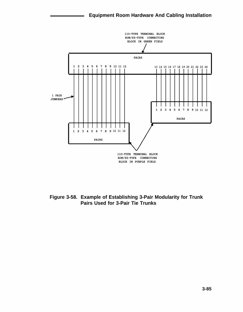
Equipment Room Hardware And Cabling Installation
11O-TYPE TERMINAL BLOCKROW/66-TYPE CONNECTINGBLOCK IN GREEN FIELD
1 PAIR
PAIRS
1 2 3 4 5 6 7 8 9 10 11 12 13 14 15 16 17 18 19 20 21 22 23 24
JUMPERS
1 2 3 4 5 6 7 8 9
1 2 3 4 5 6 7 8 9
PAIRS
10 11 12
10 11 12
PAIRS
11O-TYPE TERMINAL BLOCKROW/66-TYPE CONNECTINGBLOCK IN PURPLE FIELD
Figure 3-58. Example of Establishing 3-Pair Modularity for TrunkPairs Used for 3-Pair Tie Trunks
3-85

CHAPTER 3. EQUIPMENT ROOM DESIGN
Installing Coupled Bonding Conductor (CBC) Grounding
A CBC must be tie-wrapped to all trunk cables. The CBC connects thecabinet single-point ground block to the approved ground locatednearest the telephone company owned protector block at the buildingentrance facility (Figure 3-59).
Note: The CBC is a conductor that is connected to ground andrun adjacent to the pairs in an inside wiring cable. The mutualcoupling between the bonding conductor and the cable pairsreduces potential differences in terminating equipment. Theconductor consists of a No. 10 AWG wire that is tie-wrapped to theinside wiring cable.
APPROVED GROUNDS
An approved ground is an acceptable medium for grounding thebuilding entrance protector, entrance cable shield, or single-pointground of electronic PBX equipment. If more than one type of approvedground is available on the premises, the grounds must be bondedtogether as required in Section 250-81 of the National Electrical Code.
Metal Frame of the Building — the metal frame of the building where itis effectively grounded by one of the following grounds: acceptablemetallic water pipe, concrete encased ground, or a ground ring.
Acceptable Water Pipe — a metal underground water pipe, at least 1/2inch in diameter, in direct contact with the earth for at least 10 feet. Thepipe must be electrically continuous (or made electrically continuous bybonding around insulated joints, plastic pipe, or plastic water meters) tothe point where the protector ground wire is connected. A metallicunderground water pipe must be supplemented by the metal frame ofthe building, a concrete encased ground, or a ground ring. If thesegrounds are not available, the water pipe ground can be supplementedby one of the following types of grounds:
●
●
Metal underground gas piping system—an electrically continuousmetal underground gas piping system that is uninterrupted withinsulating sections or joints and without an outer nonconductivecoating
Other local metal underground systems or structures—localunderground structures such as tanks and piping systems
3-86

Equipment Room Hardware And Cabling Installation
●
●
Rod and pipe electrodes—a 5/8 inch (solid rod) or 3/4 inch(conduit or pipe) electrode driven to a minimum depth of 8 feet
Plate electrodes—expose a minimum of 2 square feet of metallicsurface to the exterior soil.
Concrete Encased Ground — an electrode encased by at least 2inches of concrete and located within and near the bottom of a concretefoundation or footing in direct contact with the earth. The electrodemust be at least 20 feet of one or more steel reinforcing bars or rods 1/2inch in diameter, or at least 20 feet of bare, solid copper, No. 4 AWGwire.
Ground Ring — a buried ground that encircles a building or structure ata depth of at least 2-1/2 feet below the earth’s surface. The ground ringmust be at least 20 feet of No. 2 AWG, bare, copper wire.
APPROVED FLOOR GROUNDS
Approved floor grounds are those grounds on the floor of a high-risebuilding suitable for connection to the ground terminal in the riser closetand to the PBX equipment single-point ground terminal. Such groundsmay be one of the following:
●
●
●
●
●
Building steel
The grounding conductor for the secondary side of the powertransformer feeding the floor
Metallic water pipes
Power feed metallic conduit supplying panel boards on the floor
A grounding point specifically provided in the building for thepurpose.
3-87

CHAPTER 3. EQUIPMENT ROOM DESIGN
DANGER
If the approved ground or approved floor ground can only beaccessed inside a dedicated power equipment room, thenconnections to this ground should be made by a licensedelectrician
10 GAUGE CBC
TRUNKCIRCUITS
SINGLE-POINTGROUND BLOCK
APPROVED GROUND
CABLEENTRANCETERMINAL
LIGHTNINGSURGEPROTECTOR
Figure 3-59. Installing the Coupled Bonding Conductor
3-88

Equipment Room Hardware And Cabling Installation
Installing Connector Cables Between Switch Cabinet and the Cross-ConnectField
Before starting the following procedure, refer to the heading RoutingCables From Cabinet to Cross-Connect Field in this chapter. Also, allpurple labels should have been previously installed as described in thischapter under the heading Labeling the Cross-Connect Field.
1.
2.
3.
4.
5.
6.
7.
Install "D" rings on the wall between the cable slack manager andthe terminal/connecting blocks mounted on the cross-connect field.
Install a self-sticking port label on the back of each connector onthe connector cable (Figure 3-43).
Note: Labels should be positioned so they will not beobscured by the cabinet connector retainers.
At the rear of the cabinet, connect one end of the connector cableto the assigned connector.
Dress the cable down the back of the cabinet, and through thecable slack manager to the cross-connect field.
At the cross-connect field, connect the other end of the cable to theassigned terminal/connecting block connector.
Store the cable slack in the cable slack manager.
Repeat previous Steps 2 through 6 until all cables are installed.
Installing Connector Cables Between Auxiliary Cabinet and Cross-ConnectField
Auxiliary equipment that connects to the cross-connect field can bemounted inside the auxiliary cabinet. The equipment connects to anED-1E1443-10 (Group 1) intraconnection panel mounted in the auxiliarycabinet. This intraconnection panel consists of a 110-type 100-pairwiring block mounted inside the cabinet. Auxiliary equipment isconnected to the 110-type wiring block. The wiring block is prewired tofour 25-pair female connectors mounted on the outside rear skin of thecabinet.
3-89

CHAPTER 3. EQUIPMENT ROOM DESIGN
Install connector cables between the auxiliary cabinet and cross-connectfield as follows;
1.
2.
3.
4.
5.
6.
7.
Install "D" rings on the wall between the cable slack manager andthe terminal/connecting blocks mounted on the cross-connect field.
Install a self-sticking port label on the back of each connector onthe B25A connector cable (Figure 3-43).
Note: Labels should be positioned so they will not beobscured by the cabinet connector retainers.
At the rear of the auxiliary cabinet, connect one end of theconnector cable to the assigned connector.
Dress the cable down the back of the cabinet, and through thecable slack manager to the cross-connect field.
At the cross-connect field, connect the other end of the cable to theassigned terminal/connecting block connector.
Store the cable slack in the cable slack manager.
Repeat previous Steps 2 through 6 until all cables are instaIled.
Details for installing the equipment and making the connections to thecross-connect field are included in Chapter.
Station Wiring Design
General
The following hardware and cabling is used in the station wiring design:
●
●
●
●
●
Information outlets
Station Cables
Closets
— Site locations
— Satellite locations
Adapters.
Labels
3-90

Station Wiring Design
A brief description of each of the above listed items follows. The stationwiring labels and their use are described in Chapter 4. Orderinginformation is not provided for station cables and information outlets.The ordering information for this equipment is available in the PremisesDistribution System Equipment and Supplies Catalog.
Information Outlets
Information Outlets are 8-pin modular wall jacks. Most of the outlets arewired with push-on connections. Information outlets are also availablethat connect to a double modular plug-ended 4-pair station cable runfrom the cross-connect field, a site/satellite location, or an adapter.
Station Cables
For clarity in describing the wiring in this guide, station cable is either25-pair cable, multiple 25-pair cable, or 4-pair D-inside wire (DIW) runfrom the equipment room, a site/satellite location, or an adapter to theinformation outlets. The following types of station cable are available.
●
●
Connectorized 25-pair station cable—This cable is used betweenthe equipment room and the site/satellite locations or adapters.For 110-type hardware, use an A25D cable (male to male)between the equipment room and a satellite closet, and use aB25A cable (male to female) between the equipment room and asite closet or adapter. For 66-type hardware, use an A25B cable(female to female) between the equipment room and a satellite/sitecloset or adapter. The A25B cable is available with connectors oneach end (double-ended), and also with a connector on only oneend (single-ended). Use the single-ended cable when the leadsare punched down on the connecting blocks.
Connectorized multiple 25-pair station cable—This cable can beused between the equipment room and the site/satellite locationsor adapters. This cable consists of individually sheathed 25-paircables with a factory-installed 25-pair connector on each end. For110-type hardware, use a male to female cable to connectbetween the equipment room and a site location or adapter, anduse a male to male cable to connect between the equipment roomand a satellite location. For 66-type hardware, use a female tofemale cable to connect between the equipment room and a
3-91

CHAPTER 3. EQUIPMENT ROOM DESIGN
site/satellite location or adapter. Staggered-finger cables arerecommended for all multiple 25-pair station cables.Staggered-finger cables are available in both double-ended andsingle-ended types.
●
●
●
Bulk Cable—This cable is the same as the connectorized 25-paircable or multiple 25-pair cable; however, the bulk cable is notequipped with connectors. Use this cable between the equipmentroom and satellite closets when both are equipped withpunch-down type terminal/connecting blocks.
Nonconnectorized 4-pair station cable—Use this cable when4-pair station cables are to be field-terminated on the 110-typeterminal blocks/66-type connecting blocks in the equipment roomor satellite closet and the information outlets require push-onconnections.
Single modular plug-ended 4-pair station cable(Figure 3-60)—Usethis cable between adapters and information outlets that requirepush-on connections. It can also be used when 4-pair stationcables are field-terminated on the 110-type terminalblocks/66-type connecting blocks in the equipment room orsatellite closet and modularly connected to information outlets.The station cables are available in the following lengths:
●
●
●
●
●
●
●
10 feet25 feet50 feet75 feet100 feet150 feet200 feet.
● Double modular plug-ended 4-pair station cable—Use this cableto provide nonstandard length runs between adapters andinformation outlets with push-on connections. It can also be usedbetween adapters and modularly connected information outlets. Itis available in the same lengths as the single modular plug-endedcable (see Note).
3-92

Station Wiring Design
MODULARPLUG
Figure 3-60. 4-Pair Single Modular Plug-Ended Station Cable
Note: If more than 200 feet of 4-pair station cable is required, a451A in-line adapter (double-ended modular female connector) isattached to the cable and a second 4-pair cable of the requiredlength is plugged into the adapter (Figure 3-61).
451A ADAPTER ORDERING INFORMATION
Color Comcode
Gray 103 942 272
Ivory 103 786 240
3-93

CHAPTER 3. EQUIPMENT ROOM DESIGN
STATIONCABLE INFORMATION
451AOUTLET
IN-LINEADAPTER
258A ADAPTER
4-PAIRSTATION CABLE
Figure 3-61. Example of Extending 4-Pair Station Cables
Closets
Site Locations
Site locations are closets that provide a point in the station wiring for theadministration of remote powering. Adapters are used at site locationsto terminate the 25-pair station cables and provide connection points(modular jacks) for power adapters and 4-pair station cables.
258A AND BR2580A Adapters
The 258A and BR2580A adapters (Figure 3-62) plug into a 25-pairfemale cable connector. These adapters divide the 25-pair cable into six4-pair (modular jack) circuits. See Adjunct Powering in Chapter 4 fordetails.)
3-94

Station Wiring Design
25-PAIRMALERIBBONCONNECTOR
4-PAIRMODULARJACKS
(EIGHT PINS)
4-PAIRMODULARJACKS(EIGHT PINS)
BR2580A 258AADAPTER ADAPTER
Figure 3-62. 258A and BR2580A Adapters
356A ADAPTER
The 356A adapter (Figure 3-63) plugs into a 25-pair female cableconnector. The 356A adapter divides the 25-pair cable into eight 3-paircircuits. Although the circuits are 3-pair, the adapters modular jacks willaccept the 8-pin modular plug used on the 4-pair station cable. SeeAdjunct Powering in Chapter 4 for details.)
Caution: Adapters wired similarly to the 356A should not beused. Their jacks will not accept 4-pair plugs.
3-95

CHAPTER 3. EQUIPMENT ROOM DESIGN
25-PAIRMALERIBBONCONNECTOR
4-PAIRMODULARJACKS(SIX PINS EACHCONNECTEDTO 25-PAIRRIBBONCONNECTOR)
Figure 3-63. 356A Adapter
ZD8AJ ADAPTER
Use the ZD8AJ adapter to connect a MET line cord to an informationoutlet. The adapter interchanges pairs 3 and 4 to correspond with thepair assignments for the MET. The MET line cord plugs into the adapter,and then the adapter is plugged into an information outlet.
ADAPTER ORDERING INFORMATION
BR2580A Adapter
Description Comcode258A Adapter 102 605 136
403 384 720356A Adapter 104 158 829400B Adapter 103 848 859400B2 Adapter 104 152 558ZD8AJ Adapter 103 881 421
3-96

Station Wiring Design
Satellite Locations
Satellite locations are closets that provide an administration point (usingcross-connect equipment) for station cables and where adjunct powermay be applied. The station cable circuits from the equipment roomcross-connect field are 3-pair. The hardware at the equipment room hasbeen described previously. At the satellite location, 4-pair circuits run tothe information outlets. The hardware used at the satellite location is110-type terminal blocks/66-type connecting blocks.
Satellite Locations Using 110-Type Hardware
Each terminal block has a 3-pair (white field) and a 4-pair (blue field)located on the same terminal block.
The 110A-type terminal block that can be used in the satellite closet isthe 110AE1-75FT. It must be field-terminated to both the white and bluefields.
The 300-pair 110P-type terminal blocks that can be used in the satellitecloset are the:LI 110PE1-300CT—connectorized on both the white and blue fields
●
●
110PE1-300CT/FT—connectorized on the white field andfield-terminated on the blue field
110PE1-300FT—field-terminated on both the white and bluefields.
The 900-pair 110P-type terminal blocks that can be used in the satellitecloset are the:
110PE1-900CT/FT—connectorized on the white field andfield-terminated on the blue field
●
● 110PE1-900FT—field-terminated on both the white and bluefields.
3-97

CHAPTER 3. EQUIPMENT ROOM DESIGN
●
●
●
●
Satellite Locations Using 66-Type Hardware
The 3-pair station circuits from the equipment room are terminated ona 66-type connecting block in the satellite closet white field, and thencross-connected to a 66-type connecting block in the blue field. The4-pair station circuits from the information outlets are terminated on thesatellite closet blue field. The following 66-type connecting blocks canbe used in a satellite closet;
66M1-50 connecting block
157B connecting block
154A-type backboard
166A-type bakcboard
Station Circuit Distribution From Equipment Room
The following information explains the station circuit distribution fromthe equipment room to the information outlets for new wiringinstallations. Connection diagrams are provided to show the options forrunning and connecting the station cables.
If most of the telephones/voice terminals that require remote poweringare within 250 feet of the equipment room, 4-pair station circuits are runfrom the equipment room to the information outlets. If this is not thecase, or if the customer requires 2-point administration, 3-pair stationcircuits are run from the equipment room to satellite locations. Then, the4-pair station circuits are run from the satellite locations to theinformation outlets.
4-Pair Station Circuits
Four-pair circuits can be run directly from an equipment roomcross-connect field to a 258A or BR2580A adapter as shown in Figure3-64. The 4-pair station cables connect the adapter to the informationoutlets.
3-98

Station Wiring Design
Figure 3-64. 4-Pair Circuit Distribution and Connectivity FromEquipment Room Cross-Connect Field
3-99

CHAPTER 3. EQUIPMENT ROOM DESIGN
The 4-pair station cables can be run, directly from the equipment roomto the information outlets if 4-pair terminal blocks are used in thedistribution field (Figure 3-65). The station cables must befield-terminated on the 110-type terminal blocks/66-type connectingblocks. If 110-type terminal blocks are used with a modular plug-endedstation cable, an adapter can be connected directly to the 110-typeterminal block connectors (Figure 3-66).
11O-TYPE TERMINAL BLOCK66-TYPE CONNECTING BLOCK
AT STATION SIDEOF CROSS-CONNECTFIELD OR SATELLITE
LOCATION
4-PAIR INFORMATIONCIRCUITS OUTLET
4-PAIRCIRCUIT
STATIONCABLE
BLUE (DIW)
FIELD
PUNCH-DOWNCONNECTION
Figure 3-65. 4-Pair Home Run to Equipment Room or Satellite Loca-tion
3-100

Station Wiring Design
PART OF EQUIPMENT ROOM CROSS-CONNECT FIELD(110-TYPE TERMINAL BLOCKS)
3-PAIRCONNECTING
BLOCKS
4-PAIRCONNECTING
BLOCKS
258A ORBR2580AADAPTER
INFORMATIONOUTLET
4-PAIRCIRCUIT
TOSWITCH
STATIONCABLE(DIW)
PURPLEFIELD
110P6APATCH CORDOR JUMPERS
BLUEFIELD
4-PAIR CIRCUITS
Figure 3-66. Example of 4-Pair Home Run to Equipment Room orSatellite Location Using Modular Plug-Ended StationCable
3-Pair to 4-Pair Station Circuit Distribution
Figures 3-67 and 3-68 show the 3-pair circuit distribution from anequipment room cross-connect field to a satellite location using 110-and 66-type hardware, respectively. Four-pair circuits are distributedfrom the satellite location to the information outlets.
3-101

CHAPTER 3. EQUIPMENT ROOM DESIGN
* USED WITH 110-TYPE TRMINAL BLOCKS† USED WITH 66-TYPE CONNECTING BLOCKS
NOTE:1. IF FIELD TERMINATED 66-TYPE CONNECTING BLOCKS OR 11O-TYPE TERMINAL BLOCKS ARE USED AT THE
EQUIPMENT ROOM AND SATELLITE LOCATION, BULK CABLE MAY BE USED TO RUN THE 3-PAIR CIRCUITS.
Figure 3-67. 3-Pair to 4-Pair Circuit Distribution and ConnectivityFrom Equipment Room Using 110-Type Hardware
3-102

Station Wiring Design
NOTE:1. IF FIELD TERMINATED 66-TYPE CONNECTING BLOCKS ARE USED AT
THE EQUIPMENT ROOM AND SATELLITE LOCATION, BULK CABLE MAYBE USED TO RUN THE 3-PAIR CIRCUITS.
Figure 3-68. 3-Pair to 4-Pair Circuit Distribution and ConnectivityFrom Equipment Room Using 66-Type Hardware
3-103

CHAPTER 3. EQUIPMENT ROOM DESIGN
Three-pair circuits can also be run directly from the equipment roomcross-connect field to a 356A adapter as shown in Figure 3-69.Four-pair station cables connect the adapter to the information outlets.Four-pair station cables can be run directly from a satellite location tothe information outlets as previously described (Figure 3-65 and 3-66).
PART OF EQUIPMENT ROOM CROSS-CONNECT FIELD(66-TYPE CONN BLK/100-TYPE TERM BLK
3-PAIRCONNECTINGBLOCKS
3-PAIRCONNECTINGBLOCKS B25A* OR
A25B† CABLE
TOSWITCH
PURPLEFIELD
110P6APATCHCORD ORJUMPERS
BLUEFIELD
3-PAIR CIRCUITS
356AADAPTER
INFORMATIONOUTLET
4-PAIRCIRCUIT
STATIONCABLE(DIW)
* USED WITH 11O-TYPE TERMINAL BLOCK† USED WITH 66-TYPE CONNECTING BLOCK
Figure 3-69. 3-Pair to 4-Pair Circuit Distribution and ConnectivityFrom Equipment Room Using a 356A adapter
3-104

Station Wiring Design
Table 3-I provides detailed wiring information for the 25-pair cables, theadapters, and the information outlets.
Note: Bridged taps must not be allowed on any part of the stationwiring.
Table 3-I. System Wiring
25-Pair Cable 4-Pair Cable
Voice Term Lead Functions
BR2580Aor
500,* 7400 EIA D-Inside 258A D-Inside2500, Series Term* Cable Adapter Cable Info.
Term. 7100 7300 Att. PDM Color Pin Color Outlet
No. Series Series Cons. TDM Code Num. Code Term.
1 T V1T W-BL 26 W-BL 1R V1 R BL-W 1 BL-W 2
CT TXT TXT W-O 27 W-O 3CR TXR TXR O-W 2 O-W 4P- PXT PXT W-G 28 W-G 5P+ PXR PXR G-W 3 G-W 6
P- P- W-BR 29 W-BR 7P+ P+ BR-W 4 BR-W 8
2 T V1T W-S 30 W-BL 1R V1R S-W 5 BL-W 2
CT TXT TXT R-BL 31 W-O 3CR TXR TXR BL-R 6 O-W 4P- PXT PXT R-O 32 W-G 5P+ PXR PXR O-R 7 G-W 6
P- P- R-G 33 W-BR 7P+ P+ G-R 8 BR-W 8
3 T V1T R-BR 34 W-BL 1R V1R BR-R 9 BL-W 2
CT TXT TXT R-S 35 W-O 3CR TXR TXR S-R 10 O-W 4P- PXT PXT BK-BL 36 W-G 5P+ PXR PXR BL-BK 11 G-W 6
P- P- BK-O 37 W-BR 7
P+ P+ O-BK 12 BR-W 8
* R1V2/V3 Only
3-105

CHAPTER 3. EQUIPMENT ROOM DESIGN
Table 3-I. System Wiring (Contd)
BR2580Aor
258AAdapter
PinNum.
D-InsideCableColorCode
Term.No.
4
TXT TXT
BK-GG-BKBK-BRBR-BKBK-SS-BKY-BLBL-YY-OO-YY-GG-YY-BRBR-YY-SS-Y
5
TXT
38133914401541164217431844194520462147224823
W-BLBL-WW-OO-WW-GG-WW-BRBR-WW-BLBL-WW-OO-WW-GG-WW-BRBR-WW-BLBL-WW-OO-WW-GG-W
1234567812345678123456
6
25-Pair Cable 4-Pair Cable
Info.OutletTerm.
V - B LB L - VV-OO-VV-GG-VV - B RB R - V
4924
W - B RB R - W
78
Spare
Voice Term Lead Functions
500,*2500,7100
Series
TR
7300Series
V1TV1 RCTCRP-P+
7400Series
Att.Cons.
EIATerm*PDMTDM
TXRPXTPXR
P - P-
P+ P+
T V1TR V1R
CT T X TCRP-P+
P-P+
TR
P -P+
TXRPXTPXR
TXRPXTPXR
TXRPXTPXR
P-P+
V1TV1RCT TXT TXTCR TXRP - PXTP + PXR
P-P+
TXRPXTPXR
D-insideCableColorCode
50
25
* R1V2/V3 Only
3-106

Station Wiring Design
Layout
Locating Information Outlets
The customer or marketing representative must provide floor plansshowing the information outlet locations and types (flush- orsurface-mounted) required. The floor plans must also show a completeoverview of all conduit and cabling facilities in the building.
Locating Satellites and Sites
Use the following information when determining site, satellite, or adapterlocations.
a. Keep the number of locations to a minimum.
b . To minimize the station wiring distances, centrally locate thesites/satellites, or adapters among the information outlets.
c . Site/satellite locations must be easily accessible and contain acpower receptacles.
Adapter Requirements
One 258A/BR2580A adapter is required for each 25-pair station cablecontaining 4-pair station circuits. One 356A adapter is required for each25-pair station cable containing 3-pair station circuits.
Hardware Requirements
Hardware requirements are the same as for the equipment room.
Sizing 4-Pair Station Cables
Use the scale of the floor plan to determine the approximate length ofthe station cables required per the standard Premises DistributionSystems wiring concepts.
3-107

CHAPTER 3. EQUIPMENT ROOM DESIGN
Sizing 25-Pair and Multiple 25-Pair Station Cables
Use the scale of the floor plan to determine the approximate length ofeach 25-pair station cable. The 25-pair station cables must be selectedand properly sized to make maximum use of the hardware at theequipment room or satellite location.
When using 110-type hardware, use 25-pair B25A cables to connectadapters directly to the equipment room cross-connect field or satellitelocation. Staggered-finger cables, equipped with factory-installed 25-pairconnectors at both ends (male to female), are recommended for usewhen multiple 25-pair cables are to be used between the equipmentroom or satellite location and the adapters. B25A cables are required atthe equipment room or satellite location to connect the staggered-fingercables to the 110-type terminal blocks.
When using 66-type hardware, use 25-pair A25B cables to connectadapters directly to the equipment room cross-connect field or satellitelocation. Staggered-finger 25-pair cables (double- or single-ended), arerecommended for use when multiple 25-pair cables are to be usedbetween the equipment room or satellite location and the adapters.B25A cables are required at the equipment room or satellite location toconnect the double-ended (female to female) staggered-finger cables tothe 66-type connecting blocks.
Use the following information to determine the cable size (cable pairs)required for either 3-pair or 4-pair circuits. Note the length and size onthe floor plan to aid in the ordering and installation of the station cables.
3-Pair Station Cable Circuits
To determine the size of station cables containing 3-pair circuits,multiply the number of 3-pair circuits required at the satellite location by3.5. Then, using the minimum size cable requirement, round up thecable size requirement to the next highest available cable bundle size.This will provide additional pairs for growth and compensate for the factthat every twenty-fifth pair in a cable is not used.
3-108

Station Wiring Design
4-Pair Station Cable Circuits
To determine the size of station cables containing 4-pair circuits, findout how many information outlets are served by the equipment roomcross-connect field or satellite location cross-connect field. Multiply thenumber of information outlets by 4 (see Note). Then, using the minimumsize cable requirement, round up the cable size requirement to the nexthighest available cable bundle size.
Note: This formula may not compensate for the unusedtwenty-fifth pair in all cases. If not, you must allow for it.
3-109

CHAPTER 4. STATION WIRING
Installation of Station Wiring And AssociatedHardware
Installing Station CablesInstalling 110-Type Hardware at Satellite Locations
LabelingInstalling 66-Type Hardware at Satellite Locations
LabelingInstalling 4-Pair Station CablesInstalling Information Outlets
Adjunct PoweringAdjunct Powering From the Equipment Room and SatelliteLocationsAdjunct Powering From Site LocationsAdjunct Powering From Information Outlets
Patch Cord/Jumper Installation AndAdministration
Equipment Room Cross-Connect FieldInstalling Patch Cords/Jumper WiresRemoving Patch Cords/Jumper WiresInstalling and Removing Power Adapter Cords
Satellite Locations1-Point Administration2-Point Administration
Miscellaneous Wiring InstallationInstalling System Access Terminal (SAT)Installing Attendant Console
RequirementsInstallation
Installing Selector ConsoleRequirementsInstallation
Installing INADS InterfaceRequirementsINADS Interface Installation
Installing DS1 Tie TrunksColocated DS1 Tie TrunksDS1 Tie Trunks Using 551-Type CSU
4-14-14-44-54-94-9
4-104-10
4-12
4-124-144-16
4-184-204-204-224-234-234-234-24
4-244-244-254-254-274-304-304-304-314-314-314-334-344-35
-i-

Installing Customer-Provided Alarm—System 75 XE OnlyRequirements
Installing Off-Premises Station WiringRequirementsInstallation
Installing Out-of-Building Station WiringAnalog Out-of-Building StationsDigital Out-of-Building Voice Terminals
Installing Emergency Transfer Units and Associated TelephonesRequirementsInstalling the 574-5 Power Transfer UnitInstalling the Z1A Emergency Transfer Unit
Installing External RingingRequirementsInstallation
Installing Queue Warning IndicatorRequirementsInstallation
4-364-364-364-364-374-374-374-414-454-454-454-544-674-674-674-684-684-68
-ii-

Figures
Figure 4-1.Figure 4-2.
Figure 4-3.Figure 4-4.
Figure 4-5.
Figure 4-6.
Figure 4-7.Figure 4-8.
Figure 4-9.
Figure 4-10.
Figure 4-11.Figure 4-12.Figure 4-13.Figure 4-14.Figure 4-15.Figure 4-16.
Figure 4-17.Figure 4-18.
Figure 4-19.
Figure 4-20.Figure 4-21.Figure 4-22.
Figure 4-23.
25-Pair Station Cable LabelsMultiple 25-Pair Station Cable WithFactory-Installed Staggered Fingers Connected to a110-Type Terminal Block/66-Type ConnectingBlockTypical Satellite Location Layouts3-Pair to 4-Pair Wiring Labeling From EquipmentRoom to Information Outlet4-Pair Station Wiring Labeling From EquipmentRoom to Information OutletTypical Satellite Location Layout Equipped With66-Type Connecting BlocksTypical 8-Pin Modular Information OutletsRemote Powering From the Equipment Room orSatellite LocationRemote Powering From a 258A/356A Adapter in aSite ClosetTypical Local Powering From a 400B2Adapter—Flush/Surface-Mounted InformationOutletPort Assignment Record Form1-Point Administration2-Point AdministrationConnections for SATConnections for Attendant ConsoleWiring Required at Cross-Connect Field forAttendant Console Remotely Powered From SwitchCabinet—System 75 OnlySelector Console InstallationConnections at Trunk/Auxiliary Field for INADSTrunkConnections for DS1 Tie Trunks Between TwoSystem 75 or 75 XEsConnections Between DS1 Tie Trunk and T1 CSUConnections For Off-Premises StationsConnections for One to Eight Out-of-BuildingAnalog TelephonesConnections for Each Group of EightOut-of-Building Analog telephones
4-1
4-34-4
4-6
4-8
4-94-11
4-13
4-15
4-174-194-204-214-254-26
4-294-31
4-32
4-344-354-36
4-38
4-40
-iii-

Figure 4-24.
Figure 4-25.Figure 4-26.
Figure 4-27.
Figure 4-28.
Figure 4-29.
Figure 4-30.
Figure 4-31.
Figure 4-32.
Figure 4-33.
Figure 4-34.
Figure 4-35.
Figure 4-36.
Figure 4-37.
Figure 4-38.Figure 4-39.
Connections for Digital Out-of-Building VoiceTerminals574-5 Power Transfer Unit Option SwitchesConnections at Trunk/Auxiliary Field Equipped with110-Type Hardware for Telephone Used Only forEmergency TransferConnections at Trunk/Auxiliary Field Equipped with66-Type Hardware for Telephone Used Only forEmergency TransferConnections at Trunk/Auxiliary Field Equipped with110-Type Hardware for Telephone Used forEmergency Transfer and as Normal ExtensionConnections at Trunk/Auxiliary Field Equipped with66-Type Hardware for Telephone Used forEmergency Transfer and as Normal ExtensionConnections at Trunk/Auxiliary Field for DIDMake-Busy Trunk—574-5 Power Transfer UnitConnections at Trunk/Auxiliary Field Equipped with110-Type Hardware for Telephone Used Only forEmergency Transfer (Ground Start Trunk)Connections at Trunk/Auxiliary Field Equipped with66-Type Hardware for Telephone Used Only forEmergency Transfer (Ground Start Trunks)Connections at Trunk/Auxiliary Field Equipped with110-Type Hardware for Telephone Used forEmergency Transfer and as Normal Extension(Ground Start Trunks)Connections at Trunk/Auxiliary Field Equipped with66-Type Hardware for Telephone Used forEmergency Transfer and as Normal Extension(Ground Start Trunks)Connections at Trunk/Auxiliary Field for OptionalDID Make-Busy Trunk—Z1A Emergency TransferUnitGround Wiring Example (Three Telephones UsedOnly for Emergency Transfer)Ground Wiring Example (Five Telephones Used forEmergency Transfer and as Normal Extensions)Ground Start Key InstallationConnections for External Ringing or QueueWarning Indicator
4-444-46
4-47
4-48
4-49
4-50
4-51
4-55
4-56
4-57
4-58
4-60
4-63
4-654-66
4-68
-iv-

Tables
Table 4-A. Recommended Protectors 4-42
-v-

CHAPTER 4. STATION WIRING
CHAPTER 4. STATION WIRING
HardwareInstallation of Station Wiring And Associated
Installing Station Cables
The station labels shown in Figure 4-1 must be installed on each end ofa 25-pair station cable. The labels are provided with the 201A cabIe/jackstation labels (Figure 3-42). The labels must match the labels that werepreviously installed at the cross-connect field. For example, if the cableplugs into a 110-type terminal block/66-type connecting block connectorwith jacks labeled 1 through 6, the cable label must be numbered 1through 6 (see Note).
Note: If cable/jack station labels are not available, the informationcan be written on the cable connector with a felt-tipped pen.
49-54 SIX 4-PAIRCIRCUITS
BLUE
49-56 EIGHT 3-PAIRCIRCUITS
Figure 4-1. 25-Pair Station Cable Labels
Install the station cables between the equipment room cross-connectfield and the site, satellite, or adapter locations. If 25-pair cables are runfrom the equipment room to the satellite location, A25B (for 66-typeconnecting blocks) or A25D (for 110-type terminal blocks) cables areused. If multiple 25-pair staggered finger station cables (male to male)are to be run from the equipment room to the satellite location, B25A
4-1

CHAPTER 4. STATION WIRING
cables must be used to connect the multiple 25-pair cables to the110-type terminal block/66-type connecting block connectors. Bulkcables can also be used to run from the equipment room to the satellitelocations if field-terminated 110-type terminal blocks/66-type connectingblocks are used.
If cables are to be connected to site locations or adapters, A25B (for66-type connecting blocks) or B25A (for 110-type terminal blocks)cables connect to the terminal blocks at the equipment room. TheB25A/A25B cables are run to the site locations or adapters or connectto the multiple staggered-finger station cables (Figure 4-2). Thestaggered-finger station cables are run to the site locations or adapters.
4-2

Installation of Station Wiring And Associated Hardware
B25ACABLES
STATION CABLEWITH STAGGEREDFINGERS
TO66-TYPE CONN
BLK OR 110-TYPETERM BLK
CONNECTORS
TO66-TYPE CONN
BLK OR 11O-TYPETERM BLK
CONNECTORS
TO66-TYPE CONN
BLK OR 11O-TYPETERM BLK
CONNECTORS
Figure 4-2. Multiple 25-Pair Station Cable With Factory-InstalledStaggered Fingers Connected to a 110-Type TerminalBlock/66-Type Connecting Block
4-3

CHAPTER 4. STATION WIRING
Installing 110-Type Hardware at Satellite Locations
To install 110-type terminal blocks at a satellite location, use the sameinstallation procedure described in Chapter 3 in the section Installingthe Cross-Connect Field. Figure 4-3 shows typical satellite locationlayouts.
WHITEBLANK
BLUE
75-PAIRSATELLITE 188C2
BACKBOARDFILL
188D2BACKBOARD
188D2BACKBOARD
FILL FILL
300-PAIRSATELLITE
600-PAIRSATELLITE
NOTE: WHITE FIELD CONTAINS 3-PAIR CONNECTING BLOCKSBLUE FIELD CONTAINS 4-PAIR CONNECTING BLOCKS
Figure 4-3. Typical Satellite Location Layouts
900-PAIRSATELLITE
The 3-pair station circuits from the equipment room connect to the3-pair terminal block rows (white field). The 4-pair station circuits to theinformation outlets connect to the 4-pair terminal blocks (blue field).Connections to both the 3- and 4-pair sections of the terminal blocks
4-4

Installation of Station Wiring And Associated Hardware
can be made with connectorized or field-terminated cables dependingon the type of terminal blocks used.
Labeling
Figure 4-3 shows the fill directions for the blue and white fields at asatellite location. Use the labels described in Chapter 3 in the sectionLabeling the Cross-Connect Field (with the satellite symbols) at asatellite location.
Figure 4-4 shows the labeling scheme from the white field at theequipment room to the information outlet. In the example shown, thewhite label identifying the terminal block row associated with circuits 17to 24 is connected to an identically labeled terminal block row at thesatellite closet. This is always the case for either 1-point or 2-pointadministration. See Patch Cord Installation and Administration sectionin this chapter for details.
4-5

CHAPTER 4. STATION WIRING
Figure 4-4. 3-Pair to 4-Pair Wiring Labeling From Equipment Roomto Information Outlet
4-6

Installation of Station Wiring And Associated Hardware
The satellite symbol must be installed at all connection points betweenthe blue field and the information outlet. It must also be installed at theinformation outlet itself. Figure 4-5 shows the labeling scheme for 4-paircircuits from the equipment room to the information outlets. Thelabeling scheme for 3-pair circuits from the cross-connect field to asatellite location is discussed in Installing 110-Type Hardware atSatellite Locations section in this chapter.
4-7

CHAPTER 4. STATION WIRING
Figure 4-5. 4-Pair Station Wiring Labeling From Equipment Room toInformation Outlet
4-8

Installation of Station Wiring And Associated Hardware
Installing 66-Type Hardware at Satellite Locations
To install 66-type connecting blocks at a satellite location, use theinstallation procedure described in Chapter 3 in the section Installingthe Cross-Connect Field. Figure 4-6 shows a typical satellite locationlayout.
187B1BACKBOARD
WHITE
BLUE
BLUE
3-PAIRCIRCUITS
4-PAIRCIRCUITS
Figure 4-6. Typical Satellite Location Layout Equipped With 66-Type Connecting Blocks
Three-pair station circuits are run from the equipment room to thesatellite closet white field and four-pair station circuits are run from thesatellite closet blue field to the information outlets. Connections to boththe three- and four-pair circuits can be made with connectorized orfield-terminated cables depending on the type of connecting blocksused.
Labeling
Figure 4-6 shows the fill direction for the blue and white fields at asatellite location. Lead designations are written on the connectingblocks using a permanent felt-tipped pen as described in Chapter 3 inthe section Labeling the Cross-Connect Field.
4-9
CHAPTER 4. STATION WIRING
Installing 4-Pair Station Cables
The 4-pair station cables can either be plugged into adapters orfield-terminated at the cross-connect field and then run to the informationoutlets.
Installing Information Outlets
Install the information outlets (Figure 4-7) at the designatedtelephone/voice terminal locations. See Table 3-I for connectioninformation.
4-10

Installation of Station Wiring And Associated Hardware
PRESS ON WIRECONNECTION CAPSFOR TERMINATINGWIRES ON 104ACONNECTING BLOCK
MAGNET LOCATIONS
104A COVER
MODULAR8-PIN JACKS
104A CONNECTINGBLOCK
4-PAIR WIRETERMINATIONS
4-PAIRWIRE TERMINATIONS
106AFD INFORMATION OUTLET
REAR VIEW FRONT VIEW
MODULAR8-PIN JACKS
4-PAIRSTATION CABLES
PRESS ON WIRECONNECTION CAPSFOR TERMINATINGWIRES ON 106AFDINFORMATION OUTLET FACEPLATE
Figure 4-7. Typical 8-Pin Modular Information Outlets
4-11

CHAPTER 4. STATION WIRING
Adjunct Powering
Adjunct Powering From the Equipment Room and SatelliteLocations
Adjunct power is provided at cross-connect fields or satellite locationswhen 4-pair circuits are required for station wiring. Figure 4-8 shows theconnection arrangement at the cross-connect field. The power adaptercord is routed from the connecting block the power supply.
4-12

Adjunct Powering
WHEN USING 110-TYPE HARDWARE
PART OF 110-TYPETERMINAL BLOCK(TOP VIEW)
4-PAIRCONNECTINGBLOCK
TO INDIVIDUALOR BULKPOWER SUPPLY
1-PAIRPLUG
MODULARPLUG
3-PAIRPATCHCORD
POWER ADAPTERCORD
WHEN USING 66-TYPE HARDWARE
PART OF66-TYPE
CONNECTINGBLOCK
MODULARPLUG
TOINDIVIDUALOR BULKPOWER SUPPLY
Figure 4-8. Remote Powering From the Equipment Room or Satel-Iite Location
4-13

CHAPTER 4. STATION WIRING
Adjunct Powering From Site Locations
Adjunct power can be provided through an adapter located in a sitecloset. Adjunct power is required when the length of the 4-pair stationwiring from the equipment room or satellite location is more than 250feet or when the 3-pair station wiring is run from the cross-connect fieldto a 356A adapter.
Figure 4-9 shows connections for the 258A and 356A adapters. The400B2 adapter and D6AP power cord provide power on the fourth pairof the 4-pair station cable. The D6AP power cord connects to anindividual or a bulk power supply. The D6AP power cord is available in7-, 14-, and 25-foot lengths.
4-14

Adjunct Powering
4-15

CHAPTER 4. STATION WIRING
Adjunct Powering From Information Outlets
Adjunct powering from the information outlet is described in theDEFINlTY™ Communications System and System 75, and System 85,Terminals and Adjuncts, Installation and Tests (555-015-104). Anindividual power supply is the only source of local power at aninformation outlet. Figure 4-10 shows typical connections at aninformation outlet using the 400B2 adapter and a D6AP power cord.
4-16
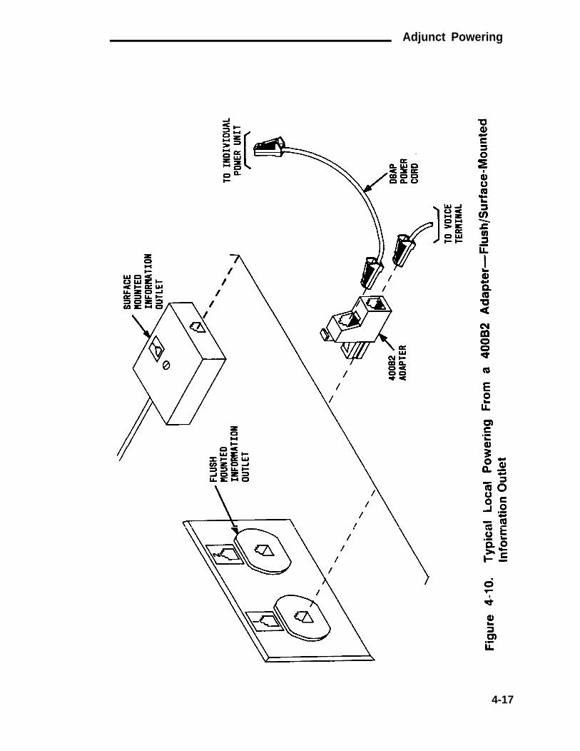
Adjunct Powering
4-17

CHAPTER 4. STATION WIRING
Patch Cord/Jumper Installation AndAdministration
Before starting the patch cord installation, obtain a copy of the PortAssignment Record forms (Figure 4-11) from the customer or marketingrepresentative. These forms contain the port assignments and identifythe extension numbers (Terminal No.) of the telephones/voice terminals.Enter the jack assignments at the equipment room and indicate ifadjunct power is required and where it is provided (cross-connect field,site/satellite closet, or information outlet).
When satellite locations are provided, enter the satellite letterdesignation (A through F) and the jack appearance in the equipmentroom on the form. Also, enter the floor designation and/or buildingdesignation if appropriate. For 1-point administration (Figure 4-12), thisentry is all that is required. The white field number always correspondsto the station jack number at the satellite location blue field.
For 2-point administration (Figure 4-13), the station jack numbers (bluefield) at the satellite locations must also be entered on the form. Forexample, the entry A1-10 indicates satellite location A, white fieldposition 1 at the equipment room and the satellite location, and stationjack number 10 at the satellite location.
4-18

Patch Cord/Jumper Installation And Administration
4-19

CHAPTER 4. STATION WIRING
EQUIPMENT SATELLITEROOM LOCATION
SINGLEADMINISTRATION
POINT
PURPLE WHITEFIELD FIELD FIELD INFORMATION
OUTLET
95
11OP6A 95PATCHCORD ORJUMPERS
WHITE BLUEFIELD
95 11OP6A 95PATCH
CORD ORJUMPERS
Figure 4-12. 1-Point Administration
Equipment Room Cross-Connect Field
The following guidelines and procedures are provided for installing andremoving patch cords/jumper wires, and power adapter cords.Administration details for changing system translations using the SystemAccess Terminal (SAT) are included in the System 75 And System 75XE—Administration (555-200-500).
Installing Patch Cords/Jumper Wires
The DEFINITY™ Communications System and System 75, and System 85,Terminals and Adjuncts, Installation and Tests (555-015-104) containsinstallation procedures for telephones/voice terminals and adjuncts.The telephones/voice terminals and adjuncts are installed before thepatch cords/jumper wires, and power adapter cords are connected.
The shortest patch cord/jumper wire should always be used to make across-connection.
4-20

Patch Cord/Jumper Installation And Administration
EQUIPMENTROOM TWO POINTS
OFADMINISTRATION
SATELLITELOCATION
PURPLEFIELD
WHITEFIELD
WHITEFIELD
BLUEFIELD INFORMATION
OUTLET
50
110P6APATCH
CORD ORJUMPERS
95 95 110P6APATCHCORD ORJUMPERS
50
Figure 4-13. 2-Point Administration
To install a patch cord/jumper wire, proceed as follows:
1 .
2 .
3 .
4 .
5 .
6 .
At the blue or white field, locate the jack number associated with thevoice terminal location.
Connect one end of the patch cord/jumper wire to theterminal/connecting block associated with this jack (see Note).
Note: An impact tool or 714B tool (for 66-type hardwareonly) is required when installing jumper wires.
At the purple field, locate the port jack number identified on the PortAssignment Record.
Route the previously connected patch cord/jumper wire to theterminal/connecting block associated with the port jack.
Connect patch cord/jumper wire to the appropriate terminal on theterminal/connecting block.
Update the Port Assignment Record (Figure 4-11).
4-21

CHAPTER 4. STATION WIRING
7 .
8 .
Repeat the procedure until all patch cords/jumper wires areinstalled.
Update system translations.
Removing Patch Cords/Jumper Wires
When it is necessary to remove a patch cord/jumper wire because atelephone/voice terminal is being removed, disconnect thetelephone/voice terminal at the information outlet. Then, remove thepatch cord/jumper wire from the cross-connect field. This gives a visualindication of the available terminal/connecting block terminalsassociated with port and station jacks. Do not leave a partially or totallydisconnected patch cord/jumper wire intermingled with the remainingpatch cords/jumper wires.
When it is necessary to rearrange patch cords/jumper wires because oftelephone/voice terminal moves, remove the patch cord/jumper wireand reinstall it even if only one end of the cross-connection is affected.This reduces entanglement and helps to assure a neat appearance.
To remove a patch cord/jumper wire, proceed as follows:
1.
2.
3.
4.
5.
6.
On the Port Assignment Record(Figure 4-11), locate theterminal/connecting block associated with the jack assignments atthe purple and white or blue fields.
At the purple field, disconnect the patch cord/jumper wire (seeNote).
Note: An impact tool or 724A tool (for 66-type hardwareonly) is required when removing jumper wires.
Lift the patch cord/jumper wire upward, taking up slack, until thepatch cord/jumper wire can be located by its movement in the patchcord trough/187B1 backboard.
Trace the other end to its connection point at the blue or white fieldand disconnect the patch cord/jumper wire.
Remove the patch cord/jumper wire from the patch cordtrough/187B1 backboard.
Update the Port Assignment Record (Figure 4-11).
4-22

Patch Cord/Jumper Installation And Administration
7. Update system translations.
Installing and Removing Power Adapter Cords
The power adapter cords are installed as described previously in theAdjunct Powering section of this chapter (Figure 4-8). The poweradapter cords can be used only with the 4-pair station circuitterminal/connecting blocks. The telephone/voice terminal and adjunctmust be installed before installing the power adapter cord and patchcord/jumper wire.
To remove a power adapter cord, proceed as follows:
1 .
2 .
3 .
4 .
5 .
6 .
On the Port Assignment Record (Figure 4-11), locate the stationjack number for the telephone/voice terminal receiving remotepower.
Unplug the power adapter cord at the power supply.
Locate the power adapter cord plug/leads on the 110-type terminalblock/66-type connecting block (blue field).
D isconnec t the power adap te r co rd / l eads f rom theterminal/connecting block.
Remove the power adapter cord from the patch cord troughs/187B1backboards.
Update the Port Assignment Record.
Satellite Locations
The guidelines for installing and removing patch cords, jumper wires,and power adapter cords at the equipment room cross-connect fieldshould be followed at a satellite location cross-conect field. Thecross-connects should be made between the white field (equipmentroom side) and the blue field (station side).
1-Point Administration
For 1-point administration (Figure 4-12), the patch cords/jumper wiresare connected between purple field terminal/connecting blocks andwhite field terminal/connecting blocks at the equipment room. Thepatch cords/jumper wires are connected between identically numbered
4-23

CHAPTER 4. STATION WIRING
white field terminal/connecting blocks (equipment room side) and bluefield terminal/connecting blocks (station side).
2-Point Administration
For 2-point administration (Figure 4-13), the patch cords/jumper wiresare connected between purple field terminal/connecting blocks andwhite field terminal/connecting blocks at the equipment room. At thesatellite location, patch cords/jumper wires are connected between thewhite field terminal/connecting blocks (equipment room side) and bluefield terminal/connecting blocks (station side) as specified on the PortAssignment Record. Update the Port Assignment Record for alladministrative changes at a satellite location.
Miscellaneous Wiring Installation
Installing System Access Terminal (SAT)
The SAT is connected to the TERM connector that is located on the rearof the control carrier. A M25B cord is used to make the connection. SeeFigure 4-14 for the connections.
4-24
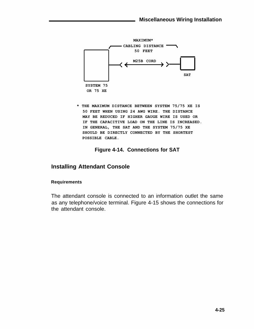
Miscellaneous Wiring Installation
MAXIMUM*CABLING DISTANCE
50 FEET
M25B CORD
SAT
SYSTEM 75OR 75 XE
* THE MAXIMUM DISTANCE BETWEEN SYSTEM 75/75 XE IS50 FEET WHEN USING 24 AWG WIRE. THE DISTANCEMAY BE REDUCED IF HIGHER GAUGE WIRE IS USED ORIF THE CAPACITIVE LOAD ON THE LINE IS INCREASED.IN GENERAL, THE SAT AND THE SYSTEM 75/75 XESHOULD BE DIRECTLY CONNECTED BY THE SHORTESTPOSSIBLE CABLE.
Figure 4-14. Connections for SAT
Installing Attendant Console
Requirements
The attendant console is connected to an information outlet the sameas any telephone/voice terminal. Figure 4-15 shows the connections forthe attendant console.
4-25

CHAPTER 4. STATION WIRING
* ACC PWR LEADS AT YELLOW FIELD, 346 BULK POWER SUPPLY, OR 329A POWER SUPPLY.KS-22911, L1 POWER SUPPLY CAN BE USED IF ATTENDANT CONSOLE IS NOT EQUIPPEDWITH OPTIONAL SELECTOR CONSOLE.
Figure 4-15. Connections for Attendant Console
Power for two consoles can be provided by the switch cabinet throughan auxiliary cable connected to the trunk/auxiliary field. Wheneverpossible, power for the primary attendant console should be providedby the switch cabinet. This makes the primary console fully operationalduring short (less than 10 seconds) power outages.
Note: The attendant console cannot be powered from the switchcabinet on the System 75 XE.
Additional attendant consoles can be remotely powered by the 346 bulkpower supply or individual power units. Refer to Adjunct Poweringsection in this chapter for details on remote powering from adjunctpower units located at satellite locations, site locations, or informationoutlets.
Note: The 329A power unit should not be used as a source ofremote power for the attendant console. A KS-22911, L1 or 346Apower unit should be used.
4-26

Miscellaneous Wiring Installation
The maximum cabling distance for an attendant console powered fromthe switch cabinet is 350 feet when using 24-gauge wire.
Installation
Install attendant console as follows:
1.
2.
Unpack console and inspect for damage.
Determine port assignment of console from Attendant ConsoleForm (see Note).
Carrier Slot Circuit
EXAMPLE: Port Number A 02 01
Note: It is recommended that the primary attendant consolebe connected to the control carrier. This allows for batteryholdover on System 75 and a better chance of uninterruptedservice on System 75 XE if a port carrier fails.
3.
4.
5.
7.
8.
If power is to be supplied from the switch cabinet (not available onSystem 75 XE), do step 4 and omit step 5; otherwise, go to step 5.
Connect jumpers (-48V and GND)from terminal/connecting block inyellow trunk/auxiliary Field to attendant console appearance on thestation side of the distribution field (Figure 4-16).
If power is to be supplied at cross-connect field, connect poweradapter cord to attendant console appearance on the station sideand a power unit located above the cross-connect field. If power isnot supplied at cross-connect field, provide power as described inAdjunct Powering section in this chapter.
6. Install patch cord/jumper wires at cross-connect field.
Connect console line jack on bottom of console to informationoutlet (Figure 4-15).
Install labels per Attendant Console Form and Display Module FormAssignments.
9. Install handset bracket on left or right side of console, as desired.
4-27

CHAPTER 4. STATION WIRING
10.
12.
Insert handset adapter on same side of handset bracket.
Note: The handset adapter is available in two models:854A-03 (black) or 854A-143 (burgundy). A bracket is notrequired for a headset.
11. Connect handset cord to jack on same side of console as handsetbracket.
Administer console per AT&T 2System 75 and System 75XE—lmplementation (555-200-651) and AT&T System 75 and System75 XE—Administration (555-200-500).
4-28

Miscellaneous Wiring Installation
WHEN USING 110-TYPE HARDWARE
TO CONTROLCARRIERAUXILIARYCONNECTOR
GRD -48
PAIR OF WIRES
TRUNK/AUXILIARYFIELD
DISTRIBUTIONFIELD
WHEN USING 66-TYPE HARDWARE
PART OF 66-TYPE CONNECTINGBLOCK ASSOCIATED WITHAUXILIARY CONNECTOR
PART OF 66-TYPE CONNECTINGBLOCK ASSOCIATED WITH
ATTENDANT CONSOLE APPEARANCE
YELLOW TRUNK/AUXILIARYFIELD
BLUE STATIONDISTRIBUTION FIELD
Figure 4-16. Wiring Required at Cross-Connect Field for AttendantConsole Remotely Powered From SwitchCabinet—System 75 Only
4-29

CHAPTER 4. STATION WIRING
Installing Selector Console
Requirements
The selector console is connected to the attendant console by a 3-footD8AC cord that is furnished with the selector console (Figure 4-17).
Note: When a basic attendant console, equipped with a selectorconsole, is powered by a 346A power unit, the slide switch on thepower unit must be set to the up position. This provides 20 wattsof power to the jack located above the slide switch. The consolemust be connected to this jack.
Installation
1.
2.
3.
Connect the D8AC cord between DXS/BLF jack on bottom ofattendant console and modular jack on bottom of selector console.
Install labels per Attendant Console Form.
Administer per AT&T System 75 and System 75 XE—Implementation(555-200-651) and AT&T System 75 and System 75XE—Administration (555-200-500).
4-30

Miscellaneous Wiring Installation
SELECTORCONSOLE
D8ACCORD
Figure 4-17. Selector Console Installation
Installing INADS Interface
Requirements
The INADS trunk should appear on the twenty-fifth pair of a RJ21Xnetwork interface jack. The INADS trunk is a two-way, rotary dial, loopstart trunk that connects to the TN731 maintenance circuit pack throughthe INADS terminals at the trunk/auxiliary cross-connect field. Figure4-18 shows a typical INADS trunk installation.
INADS Interface Installation
Install the INADS interface as follows:
1.
2.
3.
Determine INADS trunk appearance at the green trunk/auxiliarycross-connect field.
Label terminals for INADS trunk appearance (IN).
Install jumpers between INADS trunk appearance (IN) and INADSterminals.
4-31

CHAPTER 4. STATION WIRING
WHEN USING 11O-TYPE HARDWARE
TO NETWORKINTERFACEFACILITY
1 PAIR OF WIRES
TO CONTROLCARRIERAUXILIARYCONNECTOR
WHEN USING 66-TYPE HARDWARE
PART OF 66-TYPE PART OF 66-TYPE
CONNECTING BLOCK CONNECTING BLOCK
ASSOCIATED WITH ASSOCIATED WITH
CENTRAL OFFICELEADS
INADS
GREEN
AUXILIARYCONNECTOR
YELLOW
TRUNK/AUXILIARY TRUNK/AUXILIARY
FIELD FIELD
Figure 4-18. Connections at Trunk/Auxiliary Field for lNADS Trunk
4-32

Miscellaneous Wiring Installation
Installing DS1 Tie Trunks
DS1 tie trunks provide a 1.544 Mbps digital data service between twocolocated System 75 or 75 XEs or between the system and a datanetwork using T1 carrier facilities. The TN722 DS1 tie trunk circuit pack(R1V2/V3) provides connection capability to the DS1 facility for 24independent trunks. Table 3-H shows the lead designations for the DS1circuit pack.
The following connector cables are available to connect the DS1 tietrunk circuit pack to DS1 digital facilities:
●
●
●
●
C6C connector cable (comcode 104 307 327)—50-foot longshielded cable equipped with a 50-pin male connector on one endand a 15-pin male connector on the other end. Use this cable toconnect a DS1 tie trunk circuit pack to a 551-type Channel ServiceUnit (CSU).
C6D connector cable (comcode 104 307 376)—50-foot longshielded cable equipped with 50-pin male connectors on eachend. Use this cable to connect DS1 tie trunks in colocated System75 or 75 XEs.
C6E connector cable (comcode 104 307 434)—100-foot longshielded cable equipped with a 50-pin male connector on one endand a 50-pin female connector on the other end. Use this cable asan "extension" cable between the DS1 tie trunk circuit pack andthe other connector cables.
C6F connector cable (comcode 104 307 475)—50-foot longshielded cable equipped with a 50-pin male connector on one endand a three inch stub on the other end. This cable is used toconnect the DS1 tie trunk circuit pack to channel multiplexersrequiring hardwired connections.
4-33

CHAPTER 4. STATION WIRING
C6F CONNECTOR CABLE LEAD IDENTIFICATION
Wire Color Lead Connector PinDesignation Number
W-G LI* 47
G LI 22
W-BR LO 48
BR LO* 23
W-S LBACK2 49
S LBACK1 24
* Denotes ring or high side of pair.
Colocated DS1 Tie Trunks
Figure 4-19 shows the connections for two DS1 tie trunk circuit packsin colocated System 75s or 75 XEs.
DS1 TIETRUNKCIRCUITPACKTN722
MAXIMUM CABLINGDISTANCE
DS1 TIETRUNKCIRCUITPACKTN722
1310 FEET*
C6DCONNECTORCABLE *
SYSTEM SYSTEM
75 OR 75 XE 75 OR 75 XE
* FOR DISTANCES OVER 50 FEET USEC6E CONNECTOR CABLE(S) BETWEENC6D CONNECTOR CABLE AND DS1 TIETRUNK CIRCUIT PACK.
Figure 4-19. Connections for DS1 Tie Trunks Between Two System75 or 75 XEs
4-34

Miscellaneous Wiring Installation
DS1 Tie Trunks Using 551-Type CSU
Figure 4-20 shows the connections required to connect a DS1 tie trunkto a T1 CSU. The CSU is required to interface the DS1 tie trunks with the1.544 Mbps digital facility. For information on installing the CSU, refer tothe information provided with the unit. The most frequently used CSUsare the 551A, 551V, 551V EFS/R, and ESF T1. The 551V EFS/R (Rmeans retrofit) can be used to upgrade the 551V to the new ExtendedSuperframe (ESF) status.
The maximum allowable cabling distance between the DS1 tie trunk andthe CSU is:
CSU Max. Cabling Distance (feet)
551A551V551V EFS/REFS T1
DS1 TIETRUNKCIRCUITPACKTN722
8585
655655
T1 1.544 MBPSCHANNEL DIGITALSERVICE SERVICEUNIT INTERFACE
TB1
J1>
1
2
4
5
T
R
T1
R1>
C6CCONNECTORCABLE *
SYSTEM75 OR 75 XE
* FOR DISTANCES OVER 50 FEET USEC6E CONNECTOR CABLE(S) BETWEENC6C CONNECTOR CABLE AND DS1 TIETRUNK CIRCUIT PACK.
TOT1CARRIER
Figure 4-20. Connections Between DS1 Tie Trunk and T1 CSU
4-35

CHAPTER 4. STATION WIRING
Installing Customer-Provided Alarm—System 75 XE Only
Requirements
The switch provides access to a relay contact that can be used tooperate a customer-provided alarm, such as a light, bell, or similar typedevice. The relay contact can be administered so that it makes contactwhen a major, minor, or warning alarm condition exists in the switch.The circuitry required for this feature must be provided by the customer.The device, connected to the alarm leads, must not exceed a rating ofmore than 100 volts at 3/4 amp. The contact leads appear at thecross-connect field on the AUXILIARY connector. Refer to Table 3-H forthe AUXILIARY connector lead assignments.
Installing Off-Premises Station Wiring
Requirements
The cabling outside the building for off-premises stations is provided bythe local telephone company. The off-premises stations can appear onany of the RJ21X network interfaces provided for CO trunks. Only aFCC approved analog type telephone, for example, a 2500-type, can beused as an off-premises station. Figure 4-21 shows the connections for
OFF-PREMISESTERMINAL
2500500 (R1V2)
SNEAKFUSEPANEL
PART OF CROSS-CONNECT FIELD
TRUNK SIDE SWITCH SIDE
T,RTR
TN742 ORTN769CIRCUITPACKPORT
JUMPERS
GREEN PURPLE
*A25D FIELD FIELD
ORRJ21X †B25ANETWORK CABLEINTERFACE
* USE WITH 11O-TYPE TERMINAL BLOCK† USE WITH 66-TYPE CONNECTING BLOCK
Figure 4-21. Connections For Off-Premises Stations
4-36

Miscellaneous Wiring Installation
off-premises stations. The TN746 analog line circuit pack cannot be used foroff-premises stations.
Installation
To install an off-premises station:
1.
2.
3.
4.
5.
Install a B25A cable between the RJ21X network interface and asneak fuse panel.
At the cross-connect field, connect jumper wires between onerow/connecting block in the green field and up to threerows/connecting blocks in the purple field to concentrate the analogline pairs as shown in Figure 3-56.
When 110-type hardware is used, connect an A25D cable betweenthe sneak fuse panel and the 110 terminal block connectorassociated with the green row in step 3.
For 110-type hardware, install a green label on the 110-type terminalblock to identify the remote location. For 66-type hardware, writethe remote location lead designations on the connecting block with apermanent felt-tipped pen.
Administer per AT&T System 75 and System 75 XE—Implementation(555-200-651) and AT&T System 75 and System 75 XE—Administration (555-200-500).
Installing Out-of-Building Campus Stations
Out-of-building campus stations are those telephones/voice terminals that arenot physically located in the same building as the PBX equipment room butare located on the same property.
Both analog telephones and digital voice terminals can be used as out-of-building stations.
Analog Out-of-Building Stations
Figure 4-22 shows the connections for one to eight off-premises analogtelephones. The TN746 analog line circuit pack cannot be used with off-premise or out-of-building stations. Only analog telephones connected toTN742 or TN769 analog line circuit packs can be installed out-of-building.
4-37

CHAPTER 4. STATION WIRING
LOCALLY ENGINEERED
OUT-OF-BUILDINGWIRING
356AADAPTER
OUT-OF-BUILDINGANALOGTELEPHONES(NOTE) B25A
CABLE
MULTI-PAIR PROTECTORUNITS (PRIMARY PROTECTORS
WITH HEAT COILS OR EQUIVALENT)
B25A* ORA25D† CABLE
PART OF CROSS-CONNECT FIELD
STATIONSIDE
SWITCHSIDE
T
R
TN742 ORTN769CIRCUITPACK PORT
WHITEFIELD
JUMPERS PURPLEFIELD
NOTE:THE MAXIMUM CABLING DISTANCE FROM THE SWITCH CABINETTO OUT-OF-BUILDING VOICE TERMINALS IS 6000 FEET OF 24 AWG WIRE.
* USED WITH 66-TYPE CONNECTING BLOCK† USED WITH 11O-TYPE TERMINAL BLOCK
Figure 4-22. Connections for One to Eight Out-of-Building AnalogTelephones
Figure 4-23 shows the connections for up to 24 off-premises analogtelephones. Concentration of analog line pairs is used at both buildings tominimize the off-premises wiring required. At the cross-connect field,
4-38

Miscellaneous Wiring Installation
jumpers must be connected between one row/connecting block in the whitefield and up to three rows/connecting blocks in the purple field as shown inFigure 3-56. At the station location, a WP-90929, List 1 concentrator cable isused. There are eight station appearances on each of the three fingers ofthe concentrator cable.
LOCALLY ENGINEERED
OUT-OF-BUILDINGWIRING
356AADAPTER
OUT-OF-BUILDINGANALOGTELEPHONES(NOTE) A25B
CABLE CONCENTRATORCABLE(WP90929,LIST 1, CABLEASSEMBLY)
MULTI-PAIR PROTECTORUNITS (PRIMARY PROTECTORSWITH HEAT COILS OREQUIVALENT)
B25A* ORA25D† CABLE
PART OF CROSS-CONNECT FIELD
STATIONSIDE
SWITCHSIDE
T
R
TN742 ORTN769CIRCUITPACK PORT
JUMPERS
WHITEFIELD
PURPLEFIELD
NOTE:THE MAXIMUM CABLING DISTANCE FROM THE SWITCH CABINETTO OUT-OF-BUILDING VOICE TERMINALS IS 6000 FEET OF 24 AWG WIRE.
* USED WITH 66-TYPE-CONNECTING BLOCK† USED WITH 110-TYPE TERMINAL BLOCK
Figure 4-23. Connections for Each Group of Eight Out-of-Building Analogtelephones
4-39

CHAPTER 4. STATION WIRING
Carbon block, or equivalent protection is required at both building entrances.Also sneak current protection is required. Protection can be provided by a4-type protector or a 3-type protector plus a separate sneak currentprotector. The 4-type protector is equipped with a heat coil for sneak currentprotection. The 4-type protector is the preferred device because iteliminates the need to evaluate the interbuilding cable runs and itsvulnerability to power cross faults. When the 3-type protector is used, aseparate sneak current protector is required. The multi-pair protector unitsand the off-premises cabling must be locally engineered. Connectorizedmulti-pair protector units (female 25-pair connector out) are recommended.The protector units can be ordered from the Premises Distribution SystemsEquipment and Supplies Catalog.
Table 4-A shows the recommended protectors.
Table 4-A. Recommended Protectors
PROTECTORSPrimary Sneak Current
Primary * (w/heat coil) Protectors *3B1A 4B1C 79A Fuse(carbon) (carbon)
3B1E-W 4B1E-W SCP-1(wide gap (wide gapgas tube) gas tube)
3C1S 4C1S(solid state) (solid state)
* A sneak current protector is always requiredwhen a 3-type primary protector is used.
Requirement: If protectors other than those listed in Table 4-Aare to be used in domestic installations, they mustbe UL listed/approved. Also any protectors to beused in Canadian installations must be CSAcertified.
The maximum range for protection of out-of-building analog telephones (500-,2500-, or 7100- types) connected to a TN742 or TN769 analog line circuitpack through a primary protector is 6000 feet when using 24 awg wire and3600 feet when using 26 awg wire.
4-40

Miscellaneous Wiring Installation
The following voice terminals/telephones cannot be installed in an exposedenvironment:
●
●
●
7300-type voice terminals connected to TN762 hybrid line circuitpacks
MET sets connected to TN735 MET line circuit packs
analog telephones connected TN746 analog line circuit packs.
PROTECTOR ORDERING INFORMATIONDescription
361A (Carbon Block)361E-W (Wide Gap Gas Tube)3C1S (Solid State)4B1C (Carbon Block with Heat Coil)4B1E-W (Wide Gap Gas Tube with Heat Coil)4C1S (Solid State with Heat Coil)SCP-1 Sneak Current Protector79A Fuse (sneak current protector)
Comcode
102 381 779104 410 147105 514 756102 904 893104 401 856104 386 545403 617 632103 351 610
Digital Out-of-Building Voice Terminals
Protection is required at both building entrances for digital out-of-buildingvoice terminals. There are 6 different primary protectors that can be usedwith the required secondary (data link) protector to protect digital voiceterminals in an out-of-building environment.
Primary protectors have a surge breakdown voltage range of 200 to 800 voltsat 100 volts per microsecond depending on the type of device. Sneak currentprotection is also required. It can be provided by a 4-type protector or a 3-type protector plus a separate sneak current protector. The 4-type primaryprotector is equipped with a heat coil for sneak current protection. The 4-type primary protector is the preferred device because it eliminates the needto evaluate the interbuilding cable runs and its vulnerability to power crossfaults. When the 3-type primary protector is used, a separate sneak currentprotector is required.
The secondary (data link) protector is required in addition to the primaryprotector and is installed on the equipment side of the primary protector.
Table 4-B shows the recommended protectors.
4-41

CHAPTER 4. STATION WIRING
Table 4-B. Recommended Protectors
PROTECTORSPrimary *
3B1A(carbon)
79A Fuse
3B1E-W(wide gapgas tube)3C1S(solid state)
Primary Secondary(w/heat coil)
4B1C Data Link Protector(carbon) (one or eight ckts)4B1E-W
(wide gapgas tube)
4C1S(solid state)
Sneak CurrentProtectors *
SCP-1
* A sneak current protector is always required when a 3-typeprimary protector is used.
Requirement: If protectors other than those listed in Table 4-Bare to be used in domestic installations, they mustbe UL Iisted/approved. Also any protectors to beused in Canadian installations must be CSAcertified.
The maximum range for protection of out-of-building digital voice terminalsusing a primary and a secondary (data link) protector is 5000 feet when using24 awg wire and 4000 feet when using 26 awg wire. The secondary (datalink) protector used with the 7400-type digital voice terminal is an isolationtransformer and requires that the voice terminal be locally powered by anexternal power supply or through the ac power cord provided with some ofthe 7400-type voice terminals.
Except for the secondary (data link) protector, all the recommendedprotectors are plug-in 5-pin untis. There is a variety of 25-, 50-, and 100-pairprotector panels that are equipped with 66-, or 110-type connecting blocksand/or RJ21X connectors. The secondary (data link) protector is equippedwith 110-type connecting blocks and must be used with a primary protector.
4-42

Miscellaneous Wiring Installation
PROTECTOR ORDERING INFORMATIONDescription
3B1A (Carbon Block)3B1E-W (Wide Gap Gas Tube)3C1S (Solid State)4B1C (Carbon Block with Heat Coil)4B1E-W (Wide Gap Gas Tube with Heat Coil)4C1S (Solid State with Heat Coil)Data Link Protector (one ckt)Data Link Protector (8 ckts)SCP-1 Sneak Current Protector79A Fuse (sneak current protector)
Comcode
102 381 779104 410 147105 514 756102 904 893104 401 856104 386 545103 972 758103 972 733403 617 632103 351 610
Figure 4-24 shows the connections for digital out-of-building voice terminals.
4-43

CHAPTER 4. STATION WIRING
4-44

Miscellaneous Wiring Installation
Installing Emergency Transfer Units and AssociatedTelephones
Requirements
Emergency transfer capability is provided by a transfer unit mounted onthe wall next to the trunk/auxiliary cross-connect field.
Only 500- or 2500-type telephones can be used for emergency transfer.For R1V2/V3 switches, 500-and 2500-type telephones can also be usedas normal extensions. For R1V1 systems, 500-type telephones areused when the CO has only rotary dialing service and they cannot beused as normal extensions. Emergency transfer capability may beprovided on CO and Wide Area Telecommunications Service (WATS)trunks.
The following transfer units are available:
●
●
574-5 power transfer unit—Each unit serves up to five powerfailure transfer telephones. The unit provides automatic groundstart.
Z1A emergency transfer unit—Each unit serves up to six powerfailure transfer telephones. A ground-start switch is required ateach preselected telephone when ground start trunks are used.
At the cross-connect field, the transfer units are connected to a yellowterminal row/connecting block in the trunk/auxiliary field. The units arepowered (-48 V dc) from the EM TRANS RELAY PWR terminals. Thereare seven EM TRANS RELAY PWR terminal pairs which allows poweringof up to seven transfer units.
Installing the 574-5 Power Transfer Unit
The 574-5 power transfer unit has connection for five emergencytransfer telephones and is compatible with both loop start and groundstart trunks. Ten slide switches in the center of the unit (Figure 4-25) areset for the trunk type (two per trunk). The switches are set at the factoryfor ground start trunks.
4-45

CHAPTER 4. STATION WIRING
OPTION SWITCH
TRUNK TYPE SWITCHES
LOOP STARTGROUND START
1 2
BOTH SWITCHES MUST BE THROWNFOR TRUNK TYPE
CIRCUITNUMBER
12345
1 AND 23 AND 45 AND 67 AND 89 AND 10
SWITCHES
USE SMALL SCREWDRIVER TO MOVE SWITCH
Figure 4-25. 574-5 Power Transfer Unit Option Switches
When ground start trunks are used, the transfer unit automaticallyprovides ground start for each trunk without requiring any special wiringat the telephone used for emergency transfer service.
Figures 4-26 and 4-27 shows the connections on 110-type terminalblocks and 66-type connecting blocks, respectively, at the trunk/auxiliarycross-connect field for a telephone used only for emergency transfer.Figures 4-28 and 4-29 show the connections on 110-type terminalblocks and 66-type connecting blocks, respectively, at the trunk/auxiliarycross-connect field for a telephone used for emergency transfer as wellas a normal extension.
4-46

Miscellaneous Wiring Installation
4-47

CHAPTER 4. STATION WIRING
PART OF 66-TYPECONNECTING BLOCKASSOCIATED WITH PART OF 66-TYPE
CO TRUNK CONNECTING BLOCKCIRCUIT PACK ASSOCIATED WITH
(TN747) 574-5 POWERTRANSFER UNIT
TC
PART OF 66-TYPE TKCONNECTING BLOCKASSOCIATED WITHCENTRAL OFFICE
LEADS
PART OF 66-TYPECONNECTING BLOCKASSOCIATED WITH
EMERGENCYTRANSFER TERMINAL
ST
TO BLUEOR WHITEFIELD
PART OF 66-TYPECONNECTING BLOCKASSOCIATED WITH
AUXILIARYCONNECTOR
GRD
-48V
Figure 4-27. Connections at Trunk/Auxiliary Field Equipped with66-Type Hardware for Telephone Used Only for Emer-gency Transfer
4-48

Miscellaneous Wiring Installation
4-49
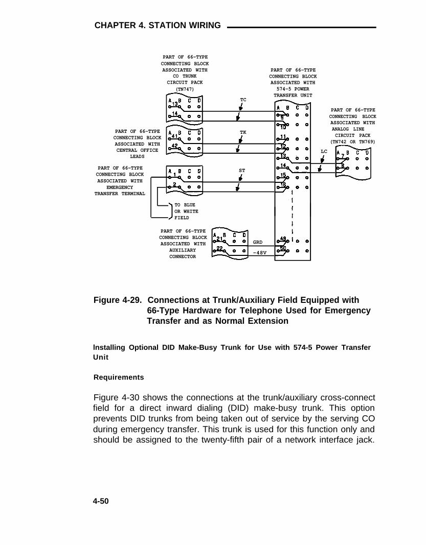
CHAPTER 4. STATION WIRING
PART OF 66-TYPECONNECTING BLOCKASSOCIATED WITH
CO TRUNKCIRCUIT PACK
(TN747)
TC
PART OF 66-TYPECONNECTING BLOCKASSOCIATED WITHCENTRAL OFFICE
TK
LCLEADS
PART OF 66-TYPECONNECTING BLOCKASSOCIATED WITH
EMERGENCYTRANSFER TERMINAL
PART OF 66-TYPECONNECTING BLOCKASSOCIATED WITH
574-5 POWERTRANSFER UNIT
PART OF 66-TYPECONNECTING BLOCKASSOCIATED WITHANALOG LINECIRCUIT PACK
(TN742 OR TN769)
ST
TO BLUEOR WHITEFIELD
PART OF 66-TYPECONNECTING BLOCKASSOCIATED WITH
AUXILIARYCONNECTOR
GRD
-48V
Figure 4-29. Connections at Trunk/Auxiliary Field Equipped with66-Type Hardware for Telephone Used for EmergencyTransfer and as Normal Extension
lnstalling Optional DID Make-Busy Trunk for Use with 574-5 Power TransferUnit
Requirements
Figure 4-30 shows the connections at the trunk/auxiliary cross-connectfield for a direct inward dialing (DID) make-busy trunk. This optionprevents DID trunks from being taken out of service by the serving COduring emergency transfer. This trunk is used for this function only andshould be assigned to the twenty-fifth pair of a network interface jack.
4-50

Miscellaneous Wiring Installation
WHEN USING 110-TYPE HARDWARE
75
100DIDMB
1 PAIR OFWIRES
TO NETWORKINTERFACEFACILITY
TO574-5POWERTRANSFERUNITIN-
ADS
WHEN USING 66-TYPE HARDWARE
PART OF 66-TYPECONNECTING BLOCKASSOCIATED WITH
574-5 POWERTRANSFER UNIT
PART OF 66-TYPECONNECTING BLOCKASSOCIATED WITH
CENTRALOFFICE LEADS DID
MB
COM3
NC3
Figure 4-30. Connections at Trunk/Auxiliary Field for DID Make-Busy Trunk—574-5 Power Transfer Unit
4-51

CHAPTER 4. STATION WIRING
Installation
Connect the DID make-busy trunk as follows:
1.
2.
At the trunk/auxiliary cross-connect field, connect a jumper fromone DID make-busy lead to terminal COM3 on the yellow emergencytransfer row/connecting block (Figure 4-30).
Connect a jumper from the other DID make-busy lead to terminalNC3 on the yellow emergency transfer row/connecting block.
Installing the Power Transfer Unit
Install the 574-5 power transfer unit as follows:
1 .
2 .
Mount the power transfer unit on the wall to the left of thetrunk/auxiliary cross-connect field. Mount additional units on thewall below the first one in a vertical column.
Connect a B25A (for 110-type hardware) or A25B (for 66-typehardware) cable from the power transfer unit to the connectorassociated with the yellow emergency transfer row/connectingblock in the trunk/auxiliary cross-connect field.
Installing Telephone Associated with 574-5 Power Transfer Unit
Trunk/Auxiliary Field Connections—Telephone Used Only for EmergencyTransfer
Install telephone as follows:
1.
2.
3.
4.
At trunk/auxiliary cross-connect field, connect a pair of wiresbetween the -48V and GRD terminals on the yellow emergencytransfer row/connecting block and the EM TRANS RELAY PWRterminal (Figures 4-28 and 4-29, respectively for 110-type and66-type hardware).
Connect CO trunk leads from the purple field to TC terminals on theyellow emergency transfer row/connecting block for each trunk.
Connect CO trunk leads from the green field to TK terminals on theyellow emergency transfer row/connecting block for each trunk.
Connect ST leads on the yellow emergency transfer row/connectingblock for each emergency transfer telephone to the ST terminalappearance in the yellow trunk/auxiliary field (see Note).
4-52

Miscellaneous Wiring Installation
Note: The ST terminal leads should be terminated on thefollowing pairs: 1, 4, 7, 10, 13, 16, 19, or 22 (the first pair of any3-pair group).
Connect the ST leads from the terminal selected in Step 4 to theassigned terminal in the blue or white station distribution field.
5.
Trunk/Auxiliary Field Connections—Telephone Used for EmergencyTransfer and as a Normal Extension
Connect telephone as follows:At trunk/auxiliary field, connect a pair of wires between the -48V andGRD terminals on the yellow emergency transfer row/connecting blockto the EM TRANS RELAY PWR terminal (Figures 4-26 and 4-27,respectively for 110-type and 66-type hardware).
1.
2.
3.
4.
5.
Connect CO trunk leads from the purple field to TC terminals on theyellow emergency transfer row/connecting block for each trunk.
Connect CO trunk leads from the green field to TK terminals on theyellow emergency transfer row/connecting block for each trunk.
Connect telephone leads from the purple analog line boardrow/connecting block to the LC terminals on the yellow emergencytransfer row/connecting block for each telephone.
Connect ST leads on the yellow emergency transfer row/connectingblock for each emergency transfer telephone to the ST terminalappearance in the purple trunk/auxiliary field.
Connect the ST leads from the terminal selected in Step 4 to the
Telephone Installation
Install telephone assigned to emergency transfer as follows:
assigned terminal in the blue or white station distribution field.
Connect telephone to the information outlet.
Install patch cords/jumper wires between the switch side and thestation side of the station distribution cross-connect field.
1 .
2 .
4-53

CHAPTER 4. STATION WIRING
Installing the Z1A Emergency Transfer Unit
If a Z1A emergency transfer unit is used with CO trunks that requireground start, a ground start switch must be installed on each telephoneto be used for emergency transfer. Ground is provided on the twenty-fifthpair of leads on each purple row/connecting block associated with aswitch cable. Ground is connected to the third pair of a 3-pair terminalappearance. This pair becomes the second pair at the informationoutlet. A ground start switch is mounted on the side of the telephoneand wired to the ground and ring leads inside the terminal.
Figures 4-31 and 4-32 show the connections on 110-type terminalblocks and 66-type connecting blocks, respectively, at the trunk/auxiliaryfield for a telephone used only for emergency transfer. Figures 4-33 and4-34 show the connections on 110-type terminal blocks and 66-typeconnecting blocks, respectively, at the trunk/auxiliary field for atelephone used for emergency transfer as well as a normal extension.
4-54

Miscellaneous Wiring Installation
4-55

CHAPTER 4. STATION WIRING
PART OF 66-TYPECONNECTING BLOCKASSOCIATED WITH
CO TRUNKCIRCUIT PACK
(TN747)
PART OF 66-TYPECONNECTING BLOCKASSOCIATED WITHZ1A EMERGENCYTRANSFER UNIT
TC
GND
GND
PART OF 66-TYPECONNECTING BLOCKASSOCIATED WITHCENTRAL OFFICE
LEADS
TKPART OF 66-TYPECONNECTING BLOCKASSOCIATED WITH
EMERGENCYTRANSFER TERMINAL
ST
PART OF 66-TYPECONNECTING BLOCKASSOCIATED WITH
AUXILIARYCONNECTOR
GRD
-48V
Figure 4-32. Connections at Trunk/Auxiliary Field Equipped with66-Type Hardware for Telephone Used Only for Emer-gency Transfer (Ground Start Trunks)
4-56

Miscellaneous Wiring Installation
4-57

CHAPTER 4. STATION WIRING
PART OF 66CONNECTING BLOCKASSOCIATED WITH
CO TRUNKCIRCUIT PACK
(TN747)
PART OF 66CONNECTING BLOCKASSOCIATED WITHZ1A EMERGENCYTRANSFER UNIT
T C
GND
GND
PART OF 66CONNECTING BLOCKASSOCIATED WITHCENTRAL OFFICE
LEADS
TKPART OF 66
CONNECTING BLOCKASSOCIATED WITH
EMERGENCYTRANSFER TERMINAL
LC
ST
PART OF 66CONNECTING BLOCKASSOCIATED WITH
AUXILIARYCONNECTOR
PART OF 66CONNECTING BLOCKASSOCIATED WITH
ANALOG LINECIRCUIT PACK
(TN742 OR TN769)
GND
-48V
Figure 4-34. Connections at Trunk/Auxiliary Field Equipped with66-Type Hardware for Telephone Used for EmergencyTransfer and as Normal Extension (Ground StartTrunks)
4-58

Miscellaneous Wiring Installation
Installing Optional DID Make-Busy Trunk for Use with Z1A EmergencyTransfer Unit
Requirements
Figure 4-35 shows the connections at the trunk/auxiliary cross-connectfield for an optional DID make-busy trunk. This option prevents DIDtrunks from being taken out of service by the serving CO duringemergency transfer. This trunk is dedicated to this purpose andappears on the twenty-fifth pair of a network interface jack.
4-59

CHAPTER 4. STATION WIRING
WHEN USING 66-TYPE HARDWARE
PART OF 66-TYPECONNECTING BLOCKASSOCIATED WITH
PART OF 66-TYPECONNECTING BLOCKASSOCIATED WITH
CENTRAL
Z1A EMERGENCYTRANSFER UNIT
OFFICE LEADS DIDMB
TK
ST
WHEN USING 11O-TYPE HARDWARE
75
100DIDMB
TO NETWORKINTERFACEFACILITY
1 PAIR OFWIRES
TOZ1AEMERGENCYTRANSFERUNIT
TK LC ST PWR
IN-ADS
Figure 4-35. Connections at Trunk/Auxiliary Field for Optional DIDMake-Busy Trunk—Z1A Emergency Transfer Unit
4-60

Miscellaneous Wiring Installation
Installation
Make connections as follows:
1.
2.
At cross-connect field, connect a jumper from one DID make-busylead to the TK terminal (first appearance) on the yellow emergencytransfer row/connecting block (Figure 4-35).
Connect a jumper from the other DID make-busy lead to the STterminal (first appearance) on the yellow emergency transferrow/connecting block.
Installing the Z1A Emergency Transfer Unit
Install the Z1A emergency transfer unit as follows:
1.
2.
Mount emergency transfer unit on the wall to the left of thetrunk/auxiliary cross-connect field. Mount additional units on thewall below the first one in a vertical column.
Connect a B25A (for 110-type hardware) or A25B (for 66-typehardware) cable from the emergency transfer unit to the connectorassociated with the yellow emergency transfer row/connectingblock in the trunk/auxiliary cross-connect field.
Installing Telephone Associated with Z1A Emergency Transfer Unit
Trunk/Auxiliary Field Connections—Telephone Used Only for EmergencyTransfer
Install telephone as follows:
1.
2.
3.
At trunk/auxiliary cross-connect field, connect a pair of wiresbetween the -48V and GRD terminals on the yellow emergencytransfer row/connecting block to the EM TRANS RELAY PWRterminal (Figures 4-31 and 4-32, respectively for 110-type and66-type hardware).
Connect CO trunk leads from the purple field to TC terminals on theyellow emergency transfer row/connecting block for each trunk.
Connect CO trunk leads from the green field to TK terminals on theyellow emergency transfer row/connecting block for each trunk.
4-61

CHAPTER 4. STATION WIRING
4.
5.
6.
Connect ST leads on the yellow emergency transfer row/connectingblock for each emergency transfer telephone to the ST terminalappearance in the yellow trunk/auxiliary cross-connect field (seeNote).
Note: The ST terminal leads should be terminated on thefollowing pairs: 1, 4, 7, 10, 13, 16, 19, or 22 (the first pair of any3-pair group).
Connect the ST leads from the terminal selected in Step 4 to theassigned terminal in the blue or white station distribution field.
If ground start is required, connect two wires from the groundterminals to the third pair of each emergency telephone appearanceon the yellow trunk/auxiliary row created in Step 4. Loop the wiresfrom the first appearance through to the last appearance if enoughground terminals are not (Figure 4-36).
4-62

Miscellaneous Wiring Installation
WHEN USING 66-TYPE HARDWARE
TO GROUNDTERMINALS
WHEN USING 110-TYPE HARDWARE
TO GROUNDTERMINALS
FIRST LASTAPPEARANCE APPEARANCE
Figure 4-36. Ground Wiring Example (Three Telephones Used Onlyfor Emergency Transfer)
4-63

CHAPTER 4. STATION WIRING
Trunk/Auxiliary Field Connections—Telephone Used for EmergencyTransfer and as a Normal Extension
Connect telephone as follows:
At trunk/auxiliary cross-connect field, connect a pair of wires betweenthe -48V and GRD terminals on the yellow emergency transferrow/connecting block and the EM TRANS RELAY PWR terminal (Figures4-33 and 4-34, respectively for 110-type and 66-type hardware).
1.
2.
3.
4.
5.
6.
Connect CO trunk leads from the purple field to TC terminals on theyellow emergency transfer row/connecting block for each trunk.
Connect CO trunk leads from the green field to TK terminals on theyellow emergency transfer row/connecting block for each trunk.
Connect telephone leads from the purple analog line boardrow/connecting block to the LC terminals on the yellow emergencytransfer row/connecting block for each telephone.
Connect ST leads on the yellow emergency transfer row/connectingblock for each emergency transfer telephone to the ST terminalappearance in the purple trunk/auxiliary cross-connect field.
Connect the ST leads from the terminal selected in Step 4 to theassigned terminal in the blue or white station distribution field.
If ground start is required, connect two wires from the groundterminals to the third pair of each emergency telephone appearanceon the yellow trunk/auxiliary row created in Step 5. Loop the wiresfrom the first appearance through to the last appearance if enoughground terminals are not (Figure 4-37).
4-64

Miscellaneous Wiring Installation
WHEN USING 66-TYPE HARDWARE
TO GROUNDTERMINALS
WHEN USING 110-TYPE HARDWARE
LAST
FIRSTAPPEARANCE
TO GROUNDTERMINALS
APPEARANCE
Figure 4-37. Ground Wiring Example (Five Telephones Used forEmergency Transfer and as Normal Extensions)
Telephone Installation
Install telephones assigned to emergency transfer as follows:
1.
2.
If ground start is required, do Steps 2 through 9 to install the groundstart switch; otherwise, go to Step 10.
Remove cover from 551A key.
4-65

CHAPTER 4. STATION WIRING
3.
4.
5.
6.
7.
8.
9.
10.
11.
Mount base of 551A key to 77A bracket using screws provided withbracket.
Remove housing from 500- or 2500-type telephone.
Connect wire from red lead (R) on telephone through 551A key toyellow and/or black lead on telephone.
Replace cover on 551A key.
Place groove in bracket over lip of telephone base (Figure 4-38).
Replace telephone housing.
Repeat Steps 2 through 8, as required.
Connect telephones to the information outlets.
Install patch cords/jumper wires between the switch side and theterminal side of the station distribution field.
Figure 4-38. Ground Start Key Installation
4-66

Miscellaneous Wiring Installation
Installing External Ringing
Requirements
Figure 4-39 shows the connections for external ringing, which isprovided by a device, such as a gong, chime, or bell, connected to aninformation outlet. The switch side of the cross-connect field isconnected to a TN742 or TN769 analog line circuit pack located in a portcarrier. The TN742 or TN769 circuit pack contains eight ports.
A maximum of 3 devices can be connected to one TN742 or TN769circuit pack port.
Installation
Install ringing device as follows:
1.
2.
3.
4.
5.
6.
Determine port assignment of Call Answer From Any Voice Terminal(CAAVT) feature from Console Parameters Form:
EXAMPLE: Port Number
Carrier Slot Circuit
Install patch cord/jumper wires at cross-connect field.
Mount the ringing device at location specified on the ExternalRinging Device Worksheet.
Connect a 2-pair line cord (modular plug at one end) from theinformation outlet to the ringing device (Figure 4-39).
Connect red (R) and green (T) leads to the ringing device.
Administer per AT&T System 75 and System 75 XE—Implementation(555-200-651) and AT&T System 75 and System 75XE—Administration (555-200-500).
B 02 01
4-67

CHAPTER 4. STATION WIRING
STATION WIRING
AC LAMPOR
RINGINGDEVICE
INFORMATIONOUTLET
SATELLITE,SITE, ORADAPTERLOCATION
PART OF CROSS-CONNECT FIELD
STATION SIDE SWITCH SIDE
R
T
RED
GREEN
T
R
TN742 ORTN769CIRCUITPACK
LINECORD
BLUE ORWHITEFIELD
110P6APATCHCORD ORJUMPERS
PURPLEFIELD
Figure 4-39. Connections for External Ringing or Queue WarningIndicator
Installing Queue Warning Indicator
Requirements
Figure 4-39 shows the connections for the queue warning indicator. Anac indicator (lamp) such as a 21C49 is optional for use as a queuewarning indication in a Uniform Call Distribution (UCD)/DirectDepartmental Calling (DDC) queue. The lamp is connected to aninformation outlet. The switch side of the cross-connect field isconnected to a TN742 or TN769 analog Line circuit pack located in aport carrier. The TN742 or TN769 circuit packs each contain eight ports.
Installation
Install queue warning indicator as follows:
1.
2.
Determine port assignment for queue warning indicator from HuntGroup Form:
EXAMPLE: Port Number B 02 01
Carrier Slot Circuit
Install patch cord/jumper wires at cross-connect field.
4-68

Miscellaneous Wiring Installation
3.
4.
5.
6.
Mount indicator at specified location.
Connect a 2-pair line cord (modular plug at one end) from theinformation outlet to the indicator (Figure 4-39).
Connect red (R) and green (T) leads to the indicator.
Administer per AT&T System 75 and System 75 XE—Implementation(555-200-651) and AT&T System 75 and System 75XE—Administration (555-200-500).
4-69

CHAPTER 5. AUXILIARY EQUIPMENTINSTALLATION
Auxiliary Equipment DescriptionInstalling Loudspeaker Paging and Music-on-Hold
RequirementsInstalling Loudspeaker Paging Access—278A Paging Adapter
RequirementsInstallation
Installing Loudspeaker Paging Access—89A Control UnitRequirementsInstallation
Installing PagePac® Paging SystemGeneralPagePac 20Installing PagePac VSInstalling PagePac 50/100/200
Installing Music-on-Hold AccessRequirementsInstallation—FCC Registered Music SourceInstallation—Non-FCC Registered Music Source
Installing Loudspeaker Paging With Background MusicRequirementsInstallation Using 278A AdapterInstallation Using 89A Control Unit
Installing Recorded Announcement EquipmentRequirementsInstallation—FCC Registered Recorded AnnouncementEquipmentlnstallation—Non-FCC Registered Recorded AnnouncementEquipment
Digital AnnouncerRequirementsInstallation
Installing Audichron Wake-Up Announcement System—R1V3Only
RequirementsInstallation
Installing Dial Dictation EquipmentInstalling 3270 Data Modules
Requirements
5-15-35-35-55-55-75-85-8
5-105-115-115-115-135-145-165-165-195-195-205-205-205-215-225-22
5-25
5-255-265-265-27
5-285-285-295-325-335-33
-i-

InstallationInstalling Processor Data Modules (PDMs)
RequirementsInstallation
Installing AP Interface—System 75 onlyRequirementsInstallation of AP Alarms
Installing AUDIX Interface—R1V3 OnlyRequirements
Installing CMS Interface—R1V3 OnlyRequirements
Installing DCS—R1V2 and R1V3Requirements
Installing PMS Interface—R1V3 OnlyRequirements
Installing Customer-Provided Terminal Using ADUsRequirementsInstallation
Installing SMDR InterfaceInterface Cabling to SMDR Output DevicePDM, Trunk Data Module, or 212-Type Modem SwitchSettings
Installing lSN InterfaceInstalling STARLAN NETWORK InterfaceInstalling Premises Lightwave System (PLS) InterfaceInstalling Processor Interface/EIA Port
5-335-365-365-375-395-395-405-425-425-425-425-435-435-445-445-455-455-455-455-46
5-495-495-525-535-55
-ii-

Figures
Figure 5-1.
Figure 5-2.
Figure 5-3.
Figure 5-4.
Figure 5-5.
Figure 5-6.Figure 5-7.
Figure 5-8.Figure 5-9.
Figure 5-10.
Figure 5-11.
Figure 5-12.
Figure 5-13.
Figure 5-14.
Figure 5-15.
Figure 5-16.
Figure 5-17.
Figure 5-18.
Figure 5-19.Figure 5-20.
Connections for Loudspeaker Paging andMusic-on-HoldConnections for Loudspeaker Paging—278AAdapterConnections for Louspeaker Paging—89A ControlUnitConnections for PagePac 20 Without Zone-Mate 9or 39Connections for PagePac 20 With Zone-Mate 9 or39Connections for PagePac VSConnections for PagePac 50/100/200 AmplicenterOnlyConnections for PagePac 50/100/200 SystemConnections for FCC Registered EquipmentProvided for Music-on-Hold/Dial DictationEquipment (Auxiliary Access)Connections for Non-FCC Registered EquipmentProvided for Music-on-Hold/Dial DictationEquipment (Auxiliary Access)Loudspeaker Paging With Background MusicConnections—278A AdapterLoudspeaker Paging With Background MusicConnections—89A Control UnitConnections for FCC Registered EquipmentProvided for Recorded Announcement/DialDictation Equipment (Analog Access)Connections for Non-FCC Registered RecordedAnnouncement/Dial Dictation Equipment (AnalogAccess)Connections for Digital Announcer Mounted inAuxiliary Cabinet.Connections for Analog Line Port to Wake-UpAnnouncement UnitConnections for Auxiliary Trunk Circuit Pack toWake-Up Announcement UnitConnections for Power Unit to Wake-UpAnnouncement UnitConnections for 3270A or 3270T Data ModuleConnections for 3270C Data Module
5-4
5-6
5-9
5-12
5-135-14
5-155-16
5-17
5-18
5-21
5-22
5-23
5-24
5-28
5-30
5-31
5-325-345-36
-iii-

Figure 5-21.Figure 5-22.Figure 5-23.
Figure 5-24.
Figure 5-25.Figure 5-26.
Figure 5-27.Figure 5-28.
Figure 5-29.
Figure 5-30.
Figure 5-31.
Figure 5-32.
Connections for PDMs in Data MountingConnections for Individual PDMsConnections at Trunk/Auxiliary Field forApplications Processor AlarmsConnections to ADU for Data Terminal Equipment(R1V2 or R1V3)SMDR Cabling for Data Terminal EquipmentSMDR Cabling for On-Premises DataCommunications EquipmentSMDR Cabling for a Remote HostSystem Voice Circuits and ISN Data CircuitsSharing an Information OutletSystem Voice Circuits and STARLAN NETWORKData Circuits Sharing an Information OutletSystem Voice Circuits and PLS Data CircuitsSharing an Information OutletDirect Connections for Processor Interface/EIAPorts Between Two System 75s or 75 XEsModem Connections for Processor Interface/EIAPorts Between Two System 75s or 75 XEs
5-385-39
5-41
5-445-47
5-485-48
5-51
5-53
5-54
5-55
5-56
-iv-

Figure 3-45.
Figure 3-46.
Figure 3-47.
Figure 3-48.
3-67
3-68
3-69
3-71
3-723-74
3-76
Figure 3-49.
Figure 3-50.Figure 3-51.
Figure 3-52.
Figure 3-53.Figure 3-54.Figure 3-55.Figure 3-56.
Figure 3-57.
3-763-783-793-80
3-82
3-84
3-853-883-933-943-953-96
Figure 3-58.
Figure 3-59.Figure 3-60.Figure 3-61.Figure 3-62.Figure 3-63.Figure 3-64.
Figure 3-65.
Cable Routing From Switch Cabinet toCross-Connect Field (Using Bottom TerminalBlocks)Cable Routing Through Cable SlackManager—Single-Cabinet Installation (UsingConnectorized Top Terminal Blocks)Cable Routing Through Cable SlackManager—Single-Cabinet Installation (UsingConnectorized Bottom Terminal Blocks)Cable Routing Through Cable SlackManager—Single-Cabinet Installation (Using66-Type Connecting Blocks With Cables RoutedFrom Top of Cross-Connect Field)Cable Routing Through Cable SlackManager—Single-Cabinet Installation (Using66-Type Connecting Blocks With Cables RoutedFrom Bottom of Cross-Connect Field)Typical Port Cable Installation at Switch CabinetControl Carrier Outputs (AUXILIARYConnector)—System 75Control Carrier Outputs (AUXILIARYConnector)—System 75 XESystem 75, Slot Addresses for 2-Carrier CabinetSystem 75, Slot Addresses for 5-Carrier CabinetSystem 75 XE Carrier Slot AddressesConnecting Trunk Pairs Used for 1-Pair TrunkCircuits; DID, Loop Start, Ground Start UsingConcentrator CablesExample of Establishing 3-Pair Modularity for TrunkPairs Used for 1-Pair Trunk Circuits; DID, LoopStart, Ground StartExample of Establishing 3-Pair Modularity for TrunkPairs Used for 3-Pair Tie TrunksInstalling the Coupled Bonding Conductor4-Pair Single Modular Plug-Ended Station CableExample of Extending 4-Pair Station Cables258A and BR2580A Adapters356A Adapter4-Pair Circuit Distribution and Connectivity FromEquipment Room Cross-Connect Field4-Pair Home Run to Equipment Room or SatelliteLocation
3-99
3-100
-v-

Figure 3-66. Example of 4-Pair Home Run to Equipment Roomor Satellite Location Using Modular Plug-EndedStation Cable
Figure 3-67. 3-Pair to 4-Pair Circuit Distribution and ConnectivityFrom Equipment Room Using 110-Type Hardware
Figure 3-68. 3-Pair to 4-Pair Circuit Distribution and ConnectivityFrom Equipment Room Using 66-Type Hardware.
Figure 3-69. 3-Pair to 4-Pair Circuit Distribution and ConnectivityFrom Equipment Room Using a 356A adapter
3-101
3-102
3-103
3-104
-vi-

Tables
Table 3-A.Table 3-B.
Table 3-C.
Table 3-D.Table 3-E.Table 3-F.Table 3-G.Table 3-H.
Table 3-I.
Distribution Field—110A-Type Terminal BlocksDistribution Field—300-Pair 110P-Type TerminalBlocksDistribution Field—900-Pair 110P-Type TerminalBlocks110-Type Hardware Requirements110 Patch Cord Requirements66-Type Hardware RequirementsLead Designations at Cross-Connect FieldAuxiliary Lead Appearances at 66-TypeCross-Connect FieldSystem Wiring
3-9
3-10
3-113-223-233-243-60
3-623-105
-vii-

CHAPTER 5. AUXILIARY EQUIPMENT INSTALLATION
CHAPTER 5. AUXILIARY EQUIPMENTINSTALLATION
Auxiliary Equipment Description
The following optional equipment is available for use with the system.
●
●
●
278A adapter—provides an interface to customer-providedequipment for the Loudspeaker Paging feature. The 278A adapterrequires -24 volt dc power, however it can be modified for -48 voltdc power by adding a D-181321 kit of parts (Comcode 103 031181).
89A control unit—provides an interface to customer-providedequipment for the Loudspeaker Paging feature. A 2012Dtransformer is required to provide -48 volt dc power to the controlunit.
PagePac paging system—provides an amplifier system for theLoudspeaker Paging feature. Three models are available:
—
—
—
PagePac 20—Provides a single zone of paging with an inputsource for music. The unit can be modified to provide 9 or 39paging zones.
PagePac VS—Provides one to three paging zones. It alsopermits all zone paging. Two optional feature cards areavailable to provide music or talk-back over paging.
PagePac 50/100/200—Provides 1 to 24 paging zones.Optional add-ons are available to provide music or talk-backover paging. Also, it is possible to use a customer-suppliedmusic source.
All PagePac models require 117-volt ac power.
● 36A voice coupler—provides an interface and also protects thecustomer-provided equipment required for InterceptTreatment—Recorded Announcement, Music-on-Hold, andRecorded Telephone Dictation Access features. The 36A voicecoupler is powered by a 2012D transformer. The 36A voicecoupler is arranged for wall-mounting.
5-1

CHAPTER 5. AUXILIARY EQUIPMENT INSTALLATION
●
●
●
●
Cook Electric Model NT7M00AA* or NT7M25AA* DigitalAnnouncer—Provides recorded announcements for RecordedAnnouncement feature. Model NT7M00AA provides one channelof voice. Model NT7M25AA provides four channels of voice. Bothmodels require an ac adapter to provide a 117-volt ac powersource.
Audichron® H9040 Wake-Up Announcement System—providesautomatic wake-up announcements for use with the hospitalityfeatures. This unit requires a power supply (to be provided locally)that is rated at -48V dc at 1.2 amps.
3270 data modules—provide a family of protocol converters thatallow 3270-type terminals to communicate with a host computerthrough the system.
Processor data modules (PDMs)—provide an interface to an AP,AUDIX, Call Management System (CMS), DistributedCommunications System (DCS), Property Management System(PMS), customer-provided terminals and computers, and StationMessage Detailed Recording (SMDR).
Asynchronous data units—provide an interface between thesystem data line circuit pack and the customer’s asynchronousdata terminals and host computers. They also can be used toprovide an interface to the PMS or SMDR equipment.
Information system network (ISN) interface—provides an interfaceto the ISN that interconnects computers and terminals on acustomer’s premises.
Star-based local area network (STARLAN) interface—providesan interface to the STARLAN network that interconnects personalcomputers, data terminals, resource units, and printers.
(Premises lightwave system (PLS) interface—provides an
●
●
●
●
interface to the PLS that allows 3270-type terminals to beconnected to a 3274 cluster controller.
* Refer to the Cook Electric Digital Announcer product description and orderinginformation for complete codes.
5-2

CHAPTER 5. AUXILIARY EQUIPMENT INSTALLATION
Installing Loudspeaker Paging and Music-on-Hold
Requirements
The Loudspeaker Paging feature provides a connection from the TN763Auxiliary Trunk to a customer-provided paging amplifier. All attendantsand voice terminal users have access to the voice paging equipment.
The Music-on-Hold feature provides a connection from the TN763Auxiliary Trunk to a customer-provided music source. All calls that areon hold, waiting in a queue, or parked will receive music to let thewaiting party know that the connection is still in effect.
The music source for the Music-on-Hold feature can also be connectedthrough a paging amplifier to provide background music over theloudspeakers.
Figure 5-1 is a block diagram that shows how the Loudspeaker Pagingand Music-on-Hold features interact. Detailed installation proceduresfor these features are included in this guide.
5-3

CHAPTER 5. AUXILIARY EQUIPMENT INSTALLATION
Figure 5-1. Connections for Loudspeaker Paging and Music-on-Hold
5-4

CHAPTER 5. AUXILIARY EQUIPMENT INSTALLATION
Installing Loudspeaker Paging Access—278A PagingAdapter
Requirements
Access to loudspeaker paging is provided by an information outlet. Theswitch side of the cross-connect field is connected to a 278A adapter.The 27A adapter is designed to operate on -24V dc. If it is to beoperated on -48V dc, it must be modified with a D-181321 kit of parts.The adapter is mounted in the auxiliary cabinet, if one is available. If anauxiliary cabinet is not available, a connectorized wiring block must belocally engineered to replace the auxiliary cabinet ED-1E443-10intra-connection panel. Six leads (T, R, SZ, SZ1, S, and S1) connect theadapter to a TN763 auxiliary trunk circuit pack located in a port carrier.A TN763 circuit pack contains four ports.
Figure 5-2 shows the connections for the Loudspeaker Paging feature.The connections are for one zone. Repeat the connections for eachpaging zone.
The connections shown in Figure 5-2 are used when the loudspeakerinterface equipment is not located in the equipment room. If theloudspeaker amplifier is located in the equipment room, the connectionsdo not have to be routed through the cross-connect field.
5-5

CHAPTER 5. AUXILIARY EQUIPMENT INSTALLATION
STATION WIRING
LOUDSPEAKERSYSTEM
INFORMATIONOUTLET
SATELLITE,SITE, ORADAPTERLOCATION
PART OF CROSS-CONNECT FIELD
STATION SIDE SWITCH SIDE
R
T
RED
GREEN
T
R
LINECORD
BLUE ORWHITEFIELD
110P6APATCHCORD ORJUMPERS
YELLOWFIELD
B25A* ORA25D† CABLE
PART OF AUXILIARY CABINET‡
25-PAIR FEMALECONNECTOR
ON ED-1E443-10PANEL
25-PAIR FEMALECONNECTOR
ON ED-1E443-10PANEL278A ADAPTER
T
R
T
R
C T
C R
T
R
BZ1
GRD
BY1
BY2
T
R
S Z
SZ1
S
S 1
T
R
S Z
SZ1
S
S1
TN763BCIRCUITPACKPORT
-V GRD
A25DCABLE
D-181321KIT
-48 VDCPOWERSOURCE
* USE WITH 66-TYPE CONNECTING BLOCK
† USE WITH 110-TYPE TERMINAL BLOCK‡ AUXILIARY CABINET IS OPTIONAL
Figure 5-2. Connections for Loudspeaker Paging—278A Adapter
5-6

CHAPTER 5. AUXILIARY EQUIPMENT INSTALLATION
Installation
Install loudspeaker paging access as follows:
1.
2.
3.
4.
5.
6.
7.
8.
Determine port assignment of paging zone(s) from LoudspeakerPaging Form:
EXAMPLE: Port Number B 02 01Carrier Slot Circuit
Identify carrier slot and label both ends of an A25D cable.
Connect the A25D cable from the assigned port carrier slot to the25-pair connector on the auxiliary cabinet’s ED-1E443-10intra-connection panel (Figure 5-2).
Connect an A25D (for 110-type hardware) or B25A for 66-typehardware) cable from the 25-pair connector on the ED-1E443-10intra-connection panel to the switch side of the cross-connect field(Figure 5-2).
For 110-type hardware, install a yellow (auxiliary) label on the110-type terminal block. For 66-type hardware, write the leaddesignations on the 66-type connecting block with a felt-tipped pen.
Remove the cover from the 278A adapter, and install the adapter ona vertical surface.
Make connections from the 278A adapter to the 110-type wiringblocks on the ED-1E443-10 intra-connection panel (Figure 5-2).
On the 278A adapter:
●
●
●
●
Install a strap between terminal BZ2 and terminal -V.
Connect a -24V dc, 40-ma power source to the -V and GRDterminals. If the auxiliary cabinet is providing the power,install a D-181321 kit of parts to reduce the -48V dc to -24Vdc.
Install straps between terminals E and F and terminals G andH for the first 278A adapter.
Install option straps between terminals C and D on each 278Aadapter.
5-7

CHAPTER 5. AUXILIARY EQUIPMENT INSTALLATION
9.
10.
11.
12.
13.
Install the cover on the 278A adapter.
Install patch cord/jumper wires at cross-connect field.
Connect a 2-pair line cord (modular plug at one end) from theinformation outlet to the loudspeaker system (Figure 5-2).
Install loudspeaker equipment per the manufacturer’s instructions.
Administer per AT&T System 75 and System 75 XE—lmplementation(555-200-651) and AT&T System 75 and System 75XE—Administration (555-200-500).
Installing Loudspeaker Paging Access—89A Control Unit
Requirements
Access to loudspeaker paging is provided by an information outlet. Theswitch side of the cross-connect field is connected to a 89A control unit.The control unit is mounted in the auxiliary cabinet, if one is available. Ifan auxiliary cabinet is not available, a connectorized wiring block mustbe locally engineered to replace the auxiliary cabinet’s ED-1E443-10intra-connection panel. Six leads (T, R, SZ, SZ1, S, and S1) connect the89A control unit to a TN763 Auxiliary Trunk circuit pack located in a portcarrier. A TN763 circuit pack contains four ports.
Figure 5-3 shows the connections for the Loudspeaker Paging feature.The connections are for one zone. Repeat the connections for eachpaging zone.
The connections shown in Figure 5-3 are used when the loudspeakerinterface equipment is not located in the equipment room. If theloudspeaker amplifier is located in the equipment room, the connectionsdo not have to be routed through the cross-connect field.
5-8

CHAPTER 5. AUXILIARY EQUIPMENT INSTALLATION
STATION WIRING
SATELLITE,SITE, ORADAPTERLOCATION
PART OF CROSS-CONNECT FIELDLOUDSPEAKER
SYSTEMINFORMATION
OUTLET STATION SIDE SWITCH SIDE
R
T
RED
GREEN
T
R
LINECORD
BLUE ORWHITEFIELD
110P6APATCH
CORD ORJUMPERS
YELLOWFIELD
B25A* ORA25D† CABLE
PART OF AUXILIARY CABINET‡
25-PAIR FEMALECONNECTOR
ON ED-1E443-10PANEL
25-PAIR FEMALECONNECTOR
ON ED-1E443-10PANEL89A CONTROL UNIT
T
R
T
R
T O-48VPOWERSUPPLY
CT
C R
PG1
BSY1
T
R
PG2
PG1
BSY1
BSY2
T
R
S Z
SZ1
S
S1
T
R
SZ
SZ1
S
S1
TN763BCIRCUITPACKPORT
AC1 AC2
A25DCABLE
2012DTRANSFORMER
* USE WITH 66-TYPE CONNECTING BLOCK† USE WITH 110-TYPE TERMINAL BLOCK‡ AUXILIARY CABINET IS OPTIONAL
Figure 5-3. Connections for Loudspeaker Paging—89A Control Unit
5-9

CHAPTER 5. AUXILIARY EQUIPMENT INSTALLATION
Installation
Install loudspeaker paging access as follows:
1.
2.
3.
4.
5.
6.
7.
8.
9.
10.
11.
12.
Determine port assignment of paging zone(s) from LoudspeakerPaging Form:
EXAMPLE: Port Number B 02 01
Carrier Slot Circuit
Identify carrier slot and label both ends of an A25D cable.
Connect the A25D cable from the assigned port carrier slot to the25-pair connector on the auxiliary cabinet’s ED-1E443-10intra-connection panel (Figure 5-3).
Connect an A25D (for 110-type hardware) or B25A for 66-typehardware) cable from the 25-pair connector on the ED-1E443-10intra-connection panel to the switch side of the cross-connect field(Figure 5-3).
For 110-type hardware, install a yellow (auxiliary) label on the110-type terminal block. For 66-type hardware, write the leaddesignations on the 66-type connecting block with a felt-tipped pen.
Remove the cover from the 89A control unit, and install the controlunit.
Make connections from the 89A control unit to the 110-type wiringblocks on the ED-1E443-10 intra-connection panel (Figure 5-3).
On the 89A control unit:
● Connect terminals PG1 and BSY1 to a -48V dc power supply.
● Connect a 2012D transformer to terminals AC1 and AC2.
Install the cover on the 89A control unit.
At the cross-connect field, install patch cord/jumper wires asrequired.
Install loudspeaker equipment per the manufacturer’s instructions.
At the information outlet, connect a 2-pair line cord (modular plug atone end) and route it to the loudspeaker equipment (Figure 5-3).
5-10

CHAPTER 5. AUXILIARY EQUIPMENT INSTALLATION
13.
14.
Plug the 2012D transformer into a 117-volt ac receptacle not undercontrol of a wall switch.
Administer per AT&T System 75 and System 75 XE—Implementation(555-200-651) and AT&T System 75 and System 75XE—Administration (555-200-500).
Installing PagePac® Paging System
General
The PagePac paging systems use a single port to provide single ormulti-zone loudspeaker paging. A PagePac system may be used inaddition to the standard loudspeaker paging and code-callingcapabilities of the system.
Three models are available:
● PagePac 20
● PagePac VS
● PagePac 50/100/200.
PagePac 20
The PagePac 20 is a 20 watt amplifier that can be used alone to providea single zone of paging (Figure 5-4) or it can be equipped with aZone-Mate 9 or 39 to provide multiple paging zones (Figure 5-5). If thePagePac 20 is used alone, a 278A adapter is required.
5-11

CHAPTER 5. AUXILIARY EQUIPMENT INSTALLATION
PART OFCROSS-CONNECT
FIELD
STATION SIDE
"PAGEPAC" 20POWERMATE
T
R
T
RT (RED)
R (GREEN)
J1 C1 (YELLOW)
C2 (BLACK) C1
C2
C1
C2
B25A* ORA25D† CABLE
"PAGEPAC"MODULAR CORD INFORMATION
OUTLETYELLOWFIELD
PART OF AUXILIARY CABINET‡
25-PAIR FEMALECONNECTOR
ON ED-1E443-10PANEL
25-PAIR FEMALECONNECTOR
ON ED-1E443-10PANEL
T
R
C1
C2
T
R278A ADAPTER
C1
C2
A
- V
BZ1
GRD
BY1
BY2
GRD
T
R
SZ
SZ1
S
S1
T
R
SZ
SZ1
S
S1
TN763BCIRCUITPACKPORT
†
D-181321KIT
A25DCABLE
-48 VDCPOWERSOURCE
* USE WITH 66-TYPE CONNECTING BLOCK† USE WITH 110-TYPE CONNECTING BLOCK‡ AUXILIARY CABINET IS OPTIONAL§ ON 278A ADAPTER, STRAP TERMINALS -V AND A
Figure 5-4. Connections for PagePac 20 Without Zone-Mate 9 or 39
5-12

CHAPTER 5. AUXILIARY EQUIPMENT INSTALLATION
PART OF CROSS-CONNECT FIELD
"PAGEPAC" 20CONTROL UNIT
INFORMATIONOUTLET STATION SIDE SWITCH SIDE
J101
1
2
3
4
NOTCONNECTED
T
R
SZ
SZ1
S
S1
T
R
SZ
SZ1
S
S1
TN763BCIRCUITPACKPORT
110P6APATCHCORD ORJUMPERSYELLOW
FIELDPURPLEFIELD"PAGEPAC"
MODULAR CORD
Figure 5-5. Connections for PagePac 20 With Zone-Mate 9 or 39
Installing PagePac VS
The PagePac VS is a 35 watt amplifier that provides up to 3 pagingzones. The PagePac VS does not require a 278A adapter. Connectionthe PagePac VS as shown in Figure 5-6.
5-13

CHAPTER 5. AUXILIARY EQUIPMENT INSTALLATION
"PAGEPAC"VS*
UIC CARD
PART OF CROSS-CONNECT FIELD
STATION SIDE SWITCH SIDE
TB2
T
R
C
N O
NOTCONNECTED
T
R
SZ
SZ1
S
S1
T
R
SZ
SZ1
S
S1
TN763BCIRCUITPACKPORT
TB1110P6APATCHCORD ORJUMPERS
YELLOWFIELD
PURPLEFIELD
* IF UIC CARD IS NOT PROVIDED, ALL CONNECTIONS AREMADE TO TB2 ON THE "PAGEPAC" VS
Figure 5-6. Connections for PagePac VS
lnstalling PagePac 50/100/200
The 50/100/200 PagePac paging system mounts directly on a wall or ona 23-inch relay rack using the appropriate adapters. The unit provides3 output wattages: 50, 100 and 200. The PagePac amplicenter can beused alone to provide a single zone of paging (Figure 5-7) or add-onunits can be provided to create a paging system with up to 24 pagingzones (Figure 5-8). If the PagePac 50/100/200 amplicenter is usedalone, a 278A adapter is required.
5-14

CHAPTER 5. AUXILIARY EQUIPMENT INSTALLATION
“PAGEPAC”50/100/200AMPLICENTER
PART OFCROSS-CONNECT
FIELD
STATION SIDE
PAGE IN
PAGE IN
MUSIC/PAGE
SIG GND
T
R
C1
C2
T
R
C1
C2
YELLOWFIELD
B25A* ORA25D† CABLE
PART OF AUXILIARY CABINET (SEE NOTE)
25-PAIR FEMALECONNECTOR
ON ED-1E443-10PANEL
25-PAIR FEMALECONNECTOR
ON ED-1E443-10PANEL
TR
TR
T
R
T
R
278A ADAPTERC1
C1
C2
SZ
SZ1
S
S1
SZ
SZ1
S
S1
TN763BCIRCUITPACKPORTC2
BZ1
GRD
BY1
BY2
GRD‡
A
- V
D-181321KIT
A25DCABLE
-48 VDCPOWERSOURCE
NOTE: AUXILIARY CABINET IS OPTIONAL
* USE WITH 66-TYPE CONNECTING BLOCK† USE WITH 110-TYPE TERMINAL BLOCK‡ STRAP TERMINALS -V AND A
Figure 5-7. Connections for PagePac 50/100/200 Amplicenter Only
5-15
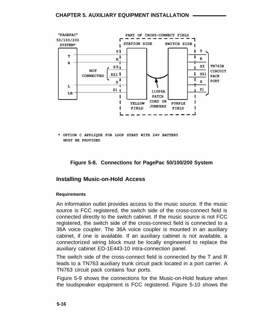
CHAPTER 5. AUXILIARY EQUIPMENT INSTALLATION
“PAGEPAC” PART OF CROSS-CONNECT FIELD50/100/200SYSTEM* STATION SIDE SWITCH SIDE
T
R
NOTCONNECTED
T
R
SZ
SZ1
S
S1
T
R
SZ
SZ1
S
S1
TN763BCIRCUITPACKPORT
L
LB 110P6APATCH
CORD ORJUMPERS
YELLOWFIELD
PURPLEFIELD
* OPTION C APPLIQUE FOR LOOP START WITH 24V BATTERYMUST BE PROVIDED
Figure 5-8. Connections for PagePac 50/100/200 System
Installing Music-on-Hold Access
Requirements
An information outlet provides access to the music source. If the musicsource is FCC registered, the switch side of the cross-connect field isconnected directly to the switch cabinet. If the music source is not FCCregistered, the switch side of the cross-connect field is connected to a36A voice coupler. The 36A voice coupler is mounted in an auxiliarycabinet, if one is available. If an auxiliary cabinet is not available, aconnectorized wiring block must be locally engineered to replace theauxiliary cabinet ED-1E443-10 intra-connection panel.
The switch side of the cross-connect field is connected by the T and Rleads to a TN763 auxiliary trunk circuit pack located in a port carrier. ATN763 circuit pack contains four ports.
Figure 5-9 shows the connections for the Music-on-Hold feature whenthe loudspeaker equipment is FCC registered. Figure 5-10 shows the
5-16

CHAPTER 5. AUXILIARY EQUIPMENT INSTALLATION
connections for the Music-on-Hold feature when the loudspeakerequipment is not FCC registered.
The connections shown in Figures 5-9 and 5-10 are used when themusic source is not located in the equipment room. If the music sourceis located in the equipment room, the connections do not have to berouted through the cross-connect field.
DIALDICTATION
STATION WIRING
EQUIPMENT SATELLITE,OR SITE, OR PART OF CROSS-CONNECT FIELD
MUSIC INFORMATION ADAPTER
SOURCE OUTLET LOCATION STATION SIDE SWITCH SIDE
R RED
T GREEN
110P6APATCH
LINECORD
CORD ORBLUE OR JUMPERS PURPLE
T
R
SZ
SZ1
S
S1
WHITE FIELDFIELD
TN763BCIRCUITPACKPORT
Figure 5-9. Connections for FCC Registered Equipment Providedfor Music-on-Hold/Dial Dictation Equipment (AuxiliaryAccess)
5-17

CHAPTER 5. AUXILIARY EQUIPMENT INSTALLATION
DIALDICTATIONEQUIPMENT
STATION WIRING
SATELLITE,SITE, OR PART OF CROSS-CONNECT FIELDO R
MUSICSOURCE
INFORMATIONOUTLET
ADAPTERLOCATION STATION SIDE SWITCH SIDE
R
T
RED
GREEN
T
R
LINECORD
B25A* ORA25D†CABLE
BLUE ORWHITEFIELD
110P6APATCHCORD ORJUMPERS
YELLOWFIELD
PART OF AUXILIARY CABINET‡
25-PAIRFEMALE CONNECTORON ED-1E443-10
PANEL
25-PAIRFEMALE CONNECTORON ED-1E443-10
PANEL36A VOICECOUPLER
T
R
T
R
T
R
CT
CR
T
R
AC ACG
T
R
SZ
SZ1
S
S1
TN763BCIRCUITPACKPORT
2012DPOWERTRANSFORMER
A25DCABLE
*†‡
USE WITH 66-TYPE CONNECTING BLOCKUSE WITH 110-TYPE TERMINAL BLOCKAUXILIARY CABINET IS OPTIONAL.
Figure 5-10. Connections for Non-FCC Registered Equipment Pro-vided for Music-on-Hold/Dial Dictation Equipment(Auxiliary Access)
5-18

CHAPTER 5. AUXILIARY EQUIPMENT INSTALLATION
Installation—FCC Registered Music Source
Install a FCC registered music source as follows:
1.
2.
3.
4.
5.
Determine feature port assignment from Feature-Related SystemParameters Form:
EXAMPLE: Port Number B 02 0 1
Carrier Slot Circuit
Install music source per the manufacturer’s instructions.
Connect a line cord (modular plug at one end) from the informationoutlet to the music source (Figure 5-9).
Install patch cord/jumper wires at the cross-connect field.
Administer per AT&T System 75 and System 75 XE—Implementation(555-200-651) and AT&T System 75 and System 75XE—Administration (555-200-500).
Installation—Non-FCC Registered Music Source
Install a nonregistered FCC music source as follows:
1.
2.
3.
4.
Determine feature port assignment from Feature-Related SystemParameters Form:
EXAMPLE: Port Number B 02 01
Identify carrier slot and place a label on both ends of an A25Dcable.
Connect the A25D cable from the assigned port carrier slot to the25-pair connector on the auxiliary cabinet ED-1E443-10
Carrier Slot Circuit
intra-connection panel (Figure 5-10).
Connect an A25D (for 110-type hardware) or B25A for 66-typehardware) cable from the 25-pair connector on the ED-1E443-10intra-connection panel to the switch side of the cross-connect field(Figure 5-10).
5-19

CHAPTER 5. AUXILIARY EQUIPMENT INSTALLATION
5.
6.
7. At the 36A voice coupler;
●
●
●
Make connections to the 110-type wiring blocks on theED-1E443-10 intra-connection panel (Figure 5-10).
Connect a 2012D transformer to terminals AC and ACG.
Install the cover.
8.
9.
10.
11.
12.
For 110-type hardware, install a yellow (auxiliary) label on the110-type terminal block. For 66-type hardware, write the leaddesignations on the 66-type connecting block with a felt-tipped pen.
Remove the cover from the 36A voice coupler, and install the voicecoupler.
Install music source per the manufacturer’s instructions.
Connect a 2-pair line cord (modular plug at one end) from theinformation outlet to the music source (Figure 5-10).
Install patch cord/jumper wires at the cross-connect field.
Plug the 2012D transformer into a 117-volt ac receptacle not undercontrol of a wall switch.
Administer per AT&T System 75 and System 75 XE—Implementation(555-200-651) and AT&T System 75 and System 75XE—Administration (555-200-500).
Installing Loudspeaker Paging With Background Music
Requirements
Figures 5-11 and 5-12 show the additional connections required whenloudspeaker paging is installed with background music. Refer to theinstallation procedures for installing loudspeaker paging (278A adapteror 89A control unit) and music-on-hold.
Installation Using 278A Adapter
Connect the 278A adapter as follows:
1 . On the 278A adapter (Figure 5-11), connect the music source toterminals M1 and M2.
5-20

CHAPTER 5. AUXILIARY EQUIPMENT INSTALLATION
2. Adjust music source level.
278A ADAPTER TOLOUDSPEAKEREQUIPMENT/ \
CT
CR
MUSIC SOURCE
M2MUSIC
M1INPUT
Figure 5-11. Loudspeaker Paging With Background MusicConnections—278A Adapter
Installation Using 89A Control Unit
Connect the 89A control unit as follows:
1 .
2 .
On the 89A control unit (Figure 5-12), connect the music source toterminals CMS1 and CMS2.
Adjust music source level.
5-21

CHAPTER 5. AUXILIARY EQUIPMENT INSTALLATION
89A CONTROL UNIT TOLOUDSPEAKEREQUIPMENT
CT
CR
MUSIC SOURCE
CMS2MUSIC
CMS1 INPUT
Figure 5-12. Loudspeaker Paging With Background MusicConnections—89A Control Unit
Requirements
Installing Recorded Announcement Equipment
Access to recorded announcement equipment is provided by aninformation outlet. If the recorded announcement equipment is FCCregistered, the switch side of the cross-connect field is connecteddirectly to the switch cabinet. If the recorded announcement equipmentis not FCC registered, the switch side of the cross-connect field isconnected to a 36A voice coupler. The 36A coupler is mounted in anauxiliary cabinet, if one is available. If an auxiliary cabinet is notavailable, a connectorized wiring block must be locally engineered toreplace the auxiliary cabinet ED-1E443-10 intra-connection panel.
The switch side of the cross-connect field is connected by the T and Rleads to a TN742 or TN769 analog line circuit pack located in a portcarrier. The TN742 or TN769 circuit pack contains eight ports.
Figure 5-13 shows the connections for the Recorded Announcementfeature when the recorded announcement equipment is FCC registered.Figure 5-14 shows the connections for the Recorded Announcement
5-22

registered.
CHAPTER 5. AUXILIARY EQUIPMENT INSTALLATION
feature when the recorded announcement equipment is not FCC
Note: For R1V3, if the TN750 Announcement circuit pack isprovided, it replaces all external announcement devices exceptthe wake-up announcement unit.
RECORDEDSTATION WIRING
ANNOUNCEMENT SATELLITE,OR DIAL SITE, OR PART OF CROSS-CONNECT FIELD
DICTATION INFORMATION ADAPTEREQUIPMENT OUTLET LOCATION STATION SIDE SWITCH SIDE
TN742,R RED T TN769,ORT GREEN R TN763B*
CIRCUITPACK PORT
110P6A
LINEBLUE OR PATCH PURPLE
CORDWHITE CORD OR FIELDFIELD JUMPERS
* TN763B CAN BE USED ONLY FOR RECORDED TELEPHONE DICTATION.
Figure 5-13. Connections for FCC Registered Equipment Providedfor Recorded Announcement/Dial Dictation Equipment(Analog Access)
5-23

CHAPTER 5. AUXILIARY EQUIPMENT INSTALLATION
RECORDEDSTATION WIRING
ANNOUNCEMENT SATELLITE,OR DIAL SITE, OR PART OF CROSS-CONNECT FIELD
DICTATION INFORMATION ADAPTEREQUIPMENT OUTLET LOCATION STATION SIDE SWITCH SIDE
R RED
T GREEN
110P6APATCH
LINEBLUE OR YELLOWWHITE CORD OR
CORDFIELD
B25A* OR FIELD JUMPERS
TR
A25D† CABLE
PART OF AUXILIARY CABINET (SEE NOTE)
25-PAIRFEMALE CONNECTORON ED-1E443-10
PANEL
25-PAIRFEMALE CONNECTORON ED-1E443-10
PANEL
PART OF CROSS-CONNECT FIELD
STATION SIDE SWITCH SIDE36A VOICECOUPLER
T
T
R
T
R
T
R
CT
CR
T
R
T
RR
AC ACG
YELLOWFIELD
110P6APATCH
CORD ORJUMPERS
PURPLEFIELD
2021DPOWER
TRANSFORMERA25DCABLE
NOTE:
*† ‡
AUXILIARY CABINET IS OPTIONAL.USE WITH 66-TYPE CONNECTING BLOCKUSE WITH 110-TYPE TERMINAL BLOCKTN763B CAN BE USED ONLY FOR RECORDED TELEPHONE DICTATION.
Figure 5-14. Connections for Non-FCC Registered RecordedAnnouncement/Dial Dictation Equipment (AnalogAccess)
TOTN742,TN769,ORTN763B‡CIRCUITPACKPORT
5-24

CHAPTER 5. AUXILIARY EQUIPMENT INSTALLATION
lnstallation—FCC Registered Recorded Announcement Equipment
Install FCC registered recorded announcement equipment as follows:
1.
2.
3.
4.
5.
Determine feature port assignment from Announcement Form:
EXAMPLE: Port Number B 0 2 01Carrier Slot Circuit
Install recorded announcement equipment per the manufacturer’sinstructions.
Connect a 2-pair line cord (modular plug at one end) from theinformation outlet to the music source (Figure 5-14).
Install patch cord/jumper wires at cross-connect field.
Administer per AT&T System 75 and System 75 XE—Implementation(555-200-651) and AT&T System 75 and System 75XE—Adminstration (555-200-500).
lnstallation—Non-FCC Registered Recorded Announcement Equipment
Install the Non-FCC registered recorded announcement equipment asfollows:
1.
2.
3.
4.
Determine feature port assignment from Announcement Form:
EXAMPLE: Port Number B 0 2 01Carrier Slot Circuit
Identify carrier slot and place a label on both ends of an A25Dcable.
Connect the A25D cable from the station side of the cross-connectfield to a 25-pair connector on the auxiliary cabinet ED-1E443-10intra-connection panel (Figure 5-14).
Connect an A25D (for 110-type hardware) or B25A (for 66-typehardware) cable from the 25-pair connector on the ED-1E443-10intra-connection panel to the switch side of the cross-connect field(Figure 5-14).
5-25

CHAPTER 5. AUXILIARY EQUIPMENT INSTALLATION
5 .
6 .
7 .
8 .
9 .
For 110-type hardware, install a yellow (auxiliary) label on the110-type terminal block. For 66-type hardware, write the leaddesignations on the 66-type connecting block with a felt-tipped pen.
Remove the cover from the 36A voice coupler, and install the voicecoupler.
At the 36A voice coupler:
Make connections to the 110-type wiring block on theED-1E443-10 intra-connection panel (Figure 5-14).
Connect a 2012D transformer to terminals AC and ACG.
Install the cover.
Install recorded announcement equipment per manufacturer’sinstructions.
Plug the 2012D transformer into a 117-volt ac receptacle not undercontrol of a wall switch.
Install patch cord/jumper wires at the cross-connect field.
Administer per AT&T System 75 and System 75 XE—Implementation(555-200-651) and AT&T System 75 and System 75XE—Administration (555-200-500).
Digital Announcer
Requirements
The Cook Electric digital announcer can be mounted in the auxiliarycabinet on a 23-inch relay rack. The relay rack includes the side bracketkit that consists of two side brackets and four mounting screws. Thevertical height is 1.75 inches. If the digital announcer is located outsidethe auxiliary cabinet, it is powered by a 117-volt ac adapter furnished byCook Electric. If the digital announcer is mounted inside the auxiliarycabinet, -48V dc power is provided by a rectifier mounted at the base ofthe cabinet. The alarm panel is mounted at the top of the cabinet.
5-26
●
●
●
10.
11.

CHAPTER 5. AUXILIARY EQUIPMENT INSTALLATION
Note: For R1V3, if the TN750 announcement circuit pack isprovided, it replaces all external announcement devices exceptthe wake-up announcement unit.
Installation
Install the digital announcer as follows:
1.
2.
3.
4.
5.
Connect an A25D (for 110-type hardware) or B25A (for 66-typehardware) cable from the 25-pair connector on the ED-1E443-10intra-connection panel to the switch side of the cross-connect field(Figure 5-15).
For 110-type hardware, install a yellow (auxiliary) label on the110-type terminal block. For 66-type hardware, write the leaddesignations on the 66-type connecting block with a felt-tipped pen.
Connect a pair of wires from the alarm panel to the digitalannouncer connector J2, pins 1 and 8.
Remove the cover from the 36A voice coupler, and install the voicecoupler.
At the 36A voice coupler:
●
●
●
●
Connect a pair of wires from terminals T and R to the digitalannouncer connector J1, pins J and K (Figure 5-15).
Make connections from terminals CT and CR to the 110-typewiring block on the ED-1E443-10 intra-connection panel(Figure 5-15).
Connect a 2012D transformer to terminals AC and ACG.
Install the cover.
6.
7.
8.
Install patch cord/jumper wires at the cross-connect field.
Plug the 2012D transformer into a 117-volt ac receptacle not undercontrol of a wall switch.
Administer per AT&T System 75 and System 75 XE—Implementation(555-200-651) and AT&T System 75 and System 75XE—Administration (555-200-500).
5-27

CHAPTER 5. AUXILIARY EQUIPMENT INSTALLATION
PART OF AUXILIARY CABINET*
25-PAIRFEMALE CONNECTOR PART OF CROSS-CONNECT FIELD
DIGITALANNOUNCER 36A VOICE
COUPLER
ON ED-1E443-10PANEL
STATION SIDE SWITCH SIDE
T
J
K
T
R
T
R
CT
CR
T
R
T
R
TOTN742 ORTN769CIRCUITPACKPORT
R
AC ACG
YELLOWFIELD
110P6APATCHCORD ORJUMPERS
PURPLEFIELD
2021DPOWERTRANSFORMER
B25A† ORA25D‡ CABLE
*†‡
AUXILIARY CABINET IS OPTIONAL.USE WITH 66-TYPE CONNECTING BLOCKUSE WITH 110-TYPE TERMINAL BLOCK
Figure 5-15. Connections for Digital Announcer Mounted in Auxil-iary Cabinet
Installing Audichron Wake-Up Announcement System—R1V3Only
Requirements
The wake-up announcement system is available as a basic unit or withmounting ears for use in the auxiliary cabinet. A battery backuparrangement is also available. The following is a list of availableequipment:
●
●
●
Basic Unit—H9040 Group 8: provides the carrier and six plug-incircuit packs required for unit operation.
Battery Pack Circuit—H9040 Group 10: provides battery backupto memory circuits during brief power outages.
Mounting Ears—H9040 Group 13: provides mounting ears thatallow the basic unit to be mounted in the auxiliary cabinet.
5-28

CHAPTER 5. AUXILIARY EQUIPMENT INSTALLATION
Access to the TN742 or TN769 analog line circuit pack is provided by aninformation outlet. The TN742 and TN769 circuit packs contain eightports. Access to the TN763B auxiliary trunk circuit pack is by the T andR leads through the cross-connect field. All four ports of the circuit packare connected to the announcement unit.
Figures 5-16 and 5-17 show the connections for the Audichron wake-upannouncement system. Figure 5-18 shows the power and groundconnections. One analog line port and an auxiliary trunk circuit pack arerequired to connect the wake-up announcement unit.
Installation
Install wakeup announcement system as follows:
1.
2.
3.
4.
5.
6.
7.
Parameters Form:
EXAMPLE:
Determine feature port assignment from Hospitality-Related System
Port Number B 02 01Carrier Slot Circuit
Connect a 2-pair line cord (modular plug on one end) from theinformation outlet (Figure 5-16) to the announcement unit.
Install patch cord at cross-connect field (Figure 5-16).
Identify the carrier slot for the auxiliary trunk circuit pack and placea label on both ends of a connector cable.
Connect the cable to the appropriate port carrier slot and dress itdown the sides of the cabinet.
Connect the cable from the bottom of the switch cabinet throughthe cable slack manager, if provided, to the connector associatedwith the 110-type terminal block/66-type connecting block row inthe purple cross-connect field.
Connect an A25D (for 110-type hardware) or B25A for 66-typehardware) cable from the 25-pair connector associated with thesecond 110-type terminal block row/66-type connecting block inthe yellow cross-connect field to connector J1 on the announcementunit (Figure 5-17).
5-29

CHAPTER 5. AUXILIARY EQUIPMENT INSTALLATION
8.
9.
10.
11.
For 110-type hardware, install a yellow (auxiliary) label on the110-type terminal block. For 66-type hardware, write the leaddesignations on the 66-type connecting block with a felt-tipped pen.
Install jumpers between the 110-type terminal block rows/66-typeconnecting blocks as shown in Figure 5-17.
Connect a -48V dc power source to the announcement unit (Figure5-18). The power source must be supplied locally and be rated at-48V dc at 1.2 amps.
Administer per AT&T System 75 and System 75 XE—Implementation(555-200-651) and AT&T System 75 and System 75XE—Administration (555-200-500).
STATION WIRING
SATELLITE,
“AUDICHRON” SITE, OR PART OF CROSS-CONNECT FIELD
H9040 INFORMATION ADAPTERANNOUNCER OUTLET LOCATION STATION SIDE SWITCH SIDE
T
RJ11
MODULAR PURPLEFIELDCORD
BLUE ORWHITEFIELD
110P6APATCH
CARD ORJUMPERS
Figure 5-16. Connections for Analog Line Port to Wake-UpAnnouncement Unit
TN742ORTN769CIRCUITPACK
5-30

CHAPTER 5. AUXILIARY EQUIPMENT INSTALLATION
PART OF CROSS-CONNECT FIELD
STATION SIDE SWITCH SIDE
"AUDICHRON"H9040
ANNOUNCER
T1
R1
S1
T2
R2
S2
T3
R3
S3
T4
R4
S4
S11
J1
1
2
9
3
4
10
5
6
11
7
8
12
13
1
2
5
7
8
11
13
14
17
19
20
23
6
A25D†OR
B25A‡CABLE
(350 FEETMAXIMUM)
YELLOWFIELD JUMPERS*
PURPLEFIELD
*
†
‡
TERMINAL NUMBERS SHOWN ARE CONNECTING BLOCK/TERMINALBLOCK NUMBERS
USE WITH 11O-TYPE TERMINAL BLOCKS
USE WITH 66-TYPE CONNECTING BLOCKS
Figure 5-17. Connections for Auxiliary Trunk Circuit Pack to Wake-Up Announcement Unit
TN763BCIRCUITPACK
5-31

CHAPTER 5. AUXILIARY EQUIPMENT INSTALLATION
“AUDICHRON”H9040 ANNOUNCER
TS1
TS2J1
J11-48V
GND3-PAIRJACK
-48V
GND
* POWER SUPPLY MUST BE PROVIDED
TO POWERSUPPLY WHENBATTERY BACKUPIS PROVIDED*
TO POWERSUPPLY WHENBATTERY BACKUPIS NOT PROVIDED*
LOCALLY AND MUST BE RATEDAT -48V DC AT 1.2 AMPS 20 GAUGE
Figure 5-18. Connections for Power Unit to Wake-Up Announce-ment Unit
Installing Dial Dictation Equipment
The procedures and requirements for installing the Recorded TelephoneDictation feature is the same as for the Recorded Announcementfeature for analog access (Figures 5-13 and 5-14) and the same asMusic-on-Hold for auxiliary trunk access (Figures 5-9 and 5-10).
The port assignment for the feature is on the Station Record Form whena TN742 or TN769 circuit pack is used. The port assignment for thefeature is on the Trunk Group Form For Customer-Provided Equipment(CPE) when a TN763 auxiliary trunk circuit pack is used.
5-32

CHAPTER 5. AUXILIARY EQUIPMENT INSTALLATION
Installing 3270 Data Modules
Requirements
The 3270 data module consists of a family of protocol converters thatallow terminals to communicate with a host computer through theswitch. The three types of 3270 data modules are:
●
●
●
3270A—asynchronous
3270C—controller
3270T—terminal.
The 3270 data modules are connected directly to TN754 digital linecircuit packs. This manual contains only the information required toconnect the data modules to the switch. Installation and testinginformation for the data modules is contained in the 3270 DATAMODULE—Coaxial-to-DCP Protocol Converter—Product Guide,999-700-520.
lnstallation
Connection to 3270A or 3270T Data Module (Figure 5-19)
1.
2.
3.
4.
Determine port assignment of 3270A or 3270T Data Module fromData Module Form:
EXAMPLE: Port Number B 02 01Carrier Slot Circuit
Connect a 4-pair line cord (modular plug on both ends) from theinformation outlet to the data module (Figure 5-19).
Install patch cord/jumper wires at cross-connect field.
Administer per AT&T System 75 and System 75 XE—Implementation(555-200-651) and AT&T System 75 and System 75XE—Administration (555-200-500).
5-33

CHAPTER 5. AUXILIARY EQUIPMENT INSTALLATION
STATION WIRING
3270A SATELLITE,OR 3270T SITE, OR PART OF CROSS-CONNECT FIELD
DATA INFORMATION ADAPTERMODULE OUTLET LOCATION STATION SIDE SWITCH SIDE
WALLJACK
TXT
TXR
PXT
PXR
110P6APATCHCORD ORJUMPERS
4-PAIRLINE
BLUE ORWHITEFIELD
PURPLEFIELD
CORD
TN754CIRCUITPACKPORT
Figure 5-19. Connections for 3270A or 3270T Data Module
5-34

CHAPTER 5. AUXILIARY EQUIPMENT INSTALLATION
Connection to 3270C Data Module (Figure 5-20)
1.
2.
3.
4.
5.
6.
7.
8.
Identify the carrier slot for the data module and place a label oneach end of a connector cable.
Connect the cable to the appropriate port carrier slot and dress itdown the side of the cabinet.
Connect an A25D (for 110-type hardware) or B25A for 66-typehardware) cable from the bottom of the switch cabinet through thecable slack manager, if provided, to the connector associated witha purple row/connecting block in the trunk/auxiliary field.
For 110-type hardware, install a yellow (auxiliary) label on the110-type terminal block. For 66-type hardware, write the leaddesignations on the 66-type connecting block with a felt-tipped pen.
Connect an A25D (for 110-type hardware) or B25A (for 66-typehardware) cable from the connector associated with a yellowrow/connecting block in the trunk/auxiliary field to location of3270C data module (see Note).
Note: The data module is located in the auxiliary cabinet, ifone is available.
Connect an A25D (for 110-type hardware) or B25A for 66-typehardware) cable to the DCP connector the on rear of the datamodule.
Install patch cord/jumper wires at cross-connect field.
Administer per AT&T System 75 and System 75 XE—Implementation(555-200-651) and AT&T System 75 and System 75XE—Administration (555-200-500).
5-35

CHAPTER 5. AUXILIARY EQUIPMENT INSTALLATION
PART OF CROSS-CONNECT FIELD
3270CDATA
MODULE STATION SIDE SWITCH SIDE
TXT TXT
TXR TXR
PXT PXT
PXR PXR
110P6APATCH
YELLOW CORD ORJUMPERS
PURPLE
B25A*FIELD FIELD
ORDCPCONNECTOR
A25D†CABLE
TN754CIRCUITPACKPORT
25-PAIR
* USE WITH 66-TYPE CONNECTING BLOCK† USE WITH 110-TYPE TERMINAL BLOCK
Figure 5-20. Connections for 3270C Data Module
Installing Processor Data Modules (PDMs)
Requirements
The interface between the system and many types of data equipment isprovided by a TN754 digital line circuit pack connected to a PDM. Thefollowing types of data equipment can be connected by a PDM:
●
●
●
●
●
●
●
AP/Adjunct—System 75 Only
AP/Terminal—System 75 Only
AUDIX/Adjunct—R1V3 Only
AUDIX/Terminal—R1V3 Only
CMS—R1V3 Only
DSC—R1V2 and R1V3
PMS—R1V3 Only
5-36

CHAPTER 5. AUXILIARY EQUIPMENT INSTALLATION
●
●
●
Journal Printer—R1V3 Only
Customer-provided terminals and host computers
SMDR
PDMs are connected to TN754 digital line circuit packs and aremounted individually or in a 71A data mounting. Each 71A datamounting can contain eight PDMs. This guide contains only theinformation required to connect the PDMs to the switch. PDM installationand testing information is contained in AT&T System 75 User’sGuide—Processor Data Module, 999-700-028.
The data mounting is connected by an A25D/B25A cable through thecross-connect field to a TN754 digital line circuit pack. The PDMs canalso be mounted and connected individually through the cross-connectfield.
Installation
Connection to Data Mounting (Figure 5-21)
1. From the Data Module Form, determine port assignment of PDMs:
EXAMPLE:Carrier Slot Circuit
Port Number B 02 01
2. Connect an A25D (for 110-type hardware) or B25A for 66-typehardware) cable to the DCP-LINE connector on the rear of the datamounting.
3. Route the cable from the data mounting to the station side of thecross-connect field.
4. For 110-type hardware, install a yellow (auxiliary) label on the110-type terminal block. For 66-type hardware, write the leaddesignations on the 66-type connecting block with a felt-tipped pen.
5. Connect patch cords/jumper wires at cross-connect field (Figure5-21).
6. Administer per AT&T System 75 and System 75 XE—lmplementation(555-200-651) and AT&T System 75 and System 75 XE—Administration(555-200-500).
5-37

CHAPTER 5. AUXILIARY EQUIPMENT INSTALLATION
PART OF25-PAIRCONNECTOR IN71A MULTIPLEDATA MOUNTING*
PART OF CROSS-CONNECT FIELD
PDM STATION SIDE SWITCH SIDE
TXT
TXR
PXT
PXR
TXT
TXR
PXT
PXR
TN754CIRCUITPACKPORT
B25A† ORA25D‡ CABLE
YELLOWFIELD
110P6APATCH
CORD ORJUMPERS
PURPLEFIELD
*
†‡
DATA MOUNTING IS LOCATED INAUXILIARY CABINET, IF PROVIDED.USE WITH 66-TYPE CONNECTING BLOCKUSE WITH 110-TYPE TERMINAL BLOCK
Figure 5-21. Connections for PDMs in Data Mounting
Connection to Individual PDMs (Figure 5-22)
1.
2.
3.
4.
Determine port assignment of PDM from Data Module Form:
EXAMPLE: Port Number B 02 01Carrier Slot Circuit
Install PDM per instructions in AT&T System 75 User’sGuide—Processor Data Module, 999-700-028.
Install patch cord/jumper wires at cross-connect field.
Administer per AT&T System 75 and System 75 XE—Implementation(555-200-651) and AT&T System 75 and System 75XE—Administration (555-200-500).
5-38

CHAPTER 5. AUXILIARY EQUIPMENT INSTALLATION
STATION WIRING
SATELLITE,SITE, OR PART OF CROSS-CONNECT FIELD
INFORMATIONOUTLET
ADAPTERLOCATION STATION SIDE SWITCH SIDE
P D MTXT
TXR
PXT
PXR
BLUE ORWHITEFIELD
110P6APATCH
CORD ORJUMPERS
PURPLEFIELD
4-PAIRLINECORD
Figure 5-22. Connections for Individual PDMs
Installing AP Interface—System 75 Only
TN754CIRCUITPACKPORT
Requirements
The interface between System 75 and the AP/adjunct or AP/terminal isthrough PDMs. The AP alarms are connected through the trunk/auxiIiaryfield to the System 75. The AP terminals can also be connected throughthe cross-connect field to the AP.
●
●
System 75, Version 1 uses interface 1 (TN716), interface 2(TN720), and interface 3 (TN719) as the required control circuitpacks.
System 75, Version 2 or 3 includes interface 1 (TN716), INterface2 (TN738), and interface 3 (TN719) as the required control circuitpacks.
Installation of the AP interface is covered in the section for installingPDMs (Figures 5-21 and 5-22).
Information for connecting the PDMs to the AP and setting the PDMoption switches is contained in Applications Processor 16—Installation,Administration, and Acceptance Test—Service Manual, 585-201-102.
5-39

CHAPTER 5. AUXILIARY EQUIPMENT INSTALLATION
Connections for the AP alarms are shown in Figure 5-23.
Installation of AP Alarms
1.
2.
3.
At the rear of the AP, connect a B25A (for 110-type hardware) orA25B (for 66-type hardware) cable to the REMOTE ALARMconnector, then route the cable to a connector associated with ayellow row/connecting block in the trunk/auxiliary field to be usedfor the AP alarms (Figure 5-23).
At the trunk/auxiliary field, connect jumpers from the seventh pairon the yellow AP row to ALARM MONITORS terminal 1M (Figure5-23). Designate the seventh pair as MAJ 1.
Connect jumpers from the ninth pair on the yellow AP row toALARM MONITOR terminals 1M (Figure 5-23). Designate the ninthpair as MIN 1.
5-40

CHAPTER 5. AUXILIARY EQUIPMENT INSTALLATION
5-41

CHAPTER 5. AUXILIARY EQUIPMENT INSTALLATION
Installing AUDIX Interface—R1V3 Only
Requirements
The interface between the switch and the AUDIX/Adjunct or AUDIXterminal is through PDMs. AUDIX terminals can also be connectedthrough the cross-connect field to the AUDIX. The large AUDIX is notsupported by System 75 or 75 XE.
●
●
System 75, Version 3 uses interface 1 (TN716), interface 2(TN738), and interface 3 (TN719) as the required control circuitpacks.
System 75, XE uses the processor interface (TN765) as therequired control circuit pack.
Connections between the AUDIX interface and the switch are coveredin the section for installing PDMs (Figures 5-21 and 5-22). The AUDIXrequires up to 16 analog circuit pack ports from the switch to beconnected through the cross-connect field to the AUDIX. Refer to Table3-H for port circuit pin numbers.
Information for connecting the PDMs to the AUDIX and setting the PDMoption switches is contained in the AUDIX-M—Installation Service Manual,585-300-103.
Installing CMS Interface—R1V3 Only
Requirements
The interface between the switch and the CMS is through PDMs.
●
●
System 75, Version 3 uses interface 1 (TN716), interface 2(TN738), and interface 3 (TN719) as the required control circuitpacks.
System 75 XE uses the processor interface (TN765) as therequired control circuit pack.
Connections between the CMS interface and the switch is covered inthe section for installing PDMs (Figures 5-21 and 5-22).
5-42

CHAPTER 5. AUXILIARY EQUIPMENT INSTALLATION
Information for connecting the PDMs to the CMS and setting the PDMoption switches is contained in the 3B2 Messaging Server Installationand Maintenance Service Manual, 585-205-110.
Installing DCS—R1V2 and R1V3
Requirements
The DCS link to the switch can be provided by either PDMs or a DS1 tietrunk.
●
●
System 75, Version 2 or 3 uses interface 1 (TN716), interface 2(TN738), and interface 3 (TN719) as the required control circuitpacks.
System 75 XE uses the processor interface (TN765) as therequired control circuit pack.
Connections for the DCS link using PDMs is covered in the section forinstalling PDMs (Figures 5-21 and 5-22). Set the PDM switches asfollows:
9600 BAUD
Switch Setting
ON
SYNC ON
INT ON
KYBD ON
AANS ON
All others OFF
The baud rate between switches may vary depending on the installation.
If the DCS link is to be provided by a DS1 tie trunk, refer to InstallingDS1 Tie Trunks.
5-43

CHAPTER 5. AUXILIARY EQUIPMENT INSTALLATION
Installing PMS Interface—R1V3 Only
Requirements
The interface between the switch and the customers PMS is throughPDMs. Connections between the PMS interface and the switch iscovered in the section for installing PDMs (Figures 5-21 and 5-22).
Refer to the appropriate vendor’s documentation for connecting thePDM to the PMS. The option switches on the PDM should be set inaccordance with the requirements for the customers PMS.
A journal printer can be used with the PMS. The connections for theprinter are the same as for the PMS. Refer to the appropriate vendor’sdocumentation for connecting the PDMs to the printer. The optionswitches on the PDM are be set according to the requirements for theprinter.
The PMS interface and the journal printers can also be installed usingAsynchronous Data Unit (ADUs). The connections are the same as fora customer-provided data terminal (Figure 5-24).
STATION WIRING
Z3A1ORZ3A2ADU
PART OF CROSS-CONNECT FIELDINFORMATION
OUTLET
SATELLITE,SITE, ORADAPTERLOCATION STATION SIDE SWITCH SIDE
TXT
TXR
PXT
PXRRS-232
110P6APATCHCORD ORJUMPERS
4-PAIRLINECORD
BLUE ORWHITEFIELD
PURPLEFIELD
Figure 5-24. Connections to ADU for Data Terminal Equipment(R1V2 or R1V3)
TN726CIRCUITPACKPORT
5-44

CHAPTER 5. AUXILIARY EQUIPMENT INSTALLATION
Installing Customer-Provided Terminal Using ADUs
Requirements
The interface between the switch and the customer’s data terminals andhost computer is through PDMs. Refer to section on installing PDMs fordetails (Figures 5-21 and 5-22).
For V2 or V3 systems only, the customer’s asynchronous data terminalscan be connected through a Z3A ADU to a TN726 data line circuit pack(Figure 5-24). Normally, the ADU is powered from the connected dataterminal. The ADU can also be remotely or locally powered using a2012D transformer equipped with a 248B adapter. ADUs connected toreceive-only printers always require external power. The need forexternal power must be determined experimentally for ADUs connectedto other devices. For details on ADU installation, refer to the Z3AAsynchronous Data Unit User’s Manual (555-401-701).
Installation
1. Determine ADU port assignment from Data Module Form:
EXAMPLE:Carrier Slot Circuit
2. Connect the RS-232 plug on the ADU to the data terminal.
Port Number B 02 01
3. Connect a 4-pair line cord (modular plug on both ends) from theinformation outlet to the ADU (Figure 5-24).
4. Install patch cord/jumper wires at cross-connect field.
5. Administer per AT&T System 75 and System 75 XE—Implementation(555-200-651) and AT&T System 75 and System 75 XE—Administration(555-200-500).
Installing SMDR Interface
The interface between the switch and SMDR is through a PDM, trunkdata module (TDM), or 212-type modem. For connections between theswitch and the PDM or TDM, refer to the section on installing PDMs(Figures 5-21 and 5-22). Administer per AT&T System 75 and System 75
5-45

CHAPTER 5. AUXILIARY EQUIPMENT INSTALLATION
XE—Implementation (555-200-651) and AT&T System 75 and System 75XE—Administration (555-200-500).
The connection between the switch and the 212-type modem is thesame as for external ringing (Figure 4-39). When a 212-type modem isused, a TN758 pooled modem circuit pack must be provided. One of thepooled modem’s conversion resources is dedicated to the SMDRoutput device. Administer per AT&T System 75 and System 75XE—Implementation (555-200-651) and AT&T System 75 and System 75XE—Administration (555-200-500).
For R1V2 or R1V3 systems only, a TN726 data Line circuit pack may beused and PDMs, TDMs, or 212-type modems are not required for theDTE. Connections between the switch and the SMDR output receivingdevice is the same as a customer-provided data terminal (Figure 5-24).
Interface Cabling to SMDR Output Device
Figure 5-25 shows the cabling required to connect the TELESEER* unit,printer, or customer-provided DTE. The M25B cable connects to the P1connector on the TELESEER unit.
* Trademark of AT&T
5-46

“TELESEER”OR
PRINTEROR
CUSTOMERPROVIDED
DTE
CHAPTER 5. AUXILIARY EQUIPMENT INSTALLATION
50 FEETMAXIMUM
M25B PDM
M25BM1OM
NULL MODEMCABLE
M25B TRUNKDATA
MODULE
M25BMODEM
Figure 5-25. SMDR Cabling for Data Terminal Equipment
5-47

CHAPTER 5. AUXILIARY EQUIPMENT INSTALLATION
Figure 5-26 shows the cabling required to connect the 94A LSU, aprinter, or customer-provided data communications equipment (DCE).The M25B cable connects to the C1 connector on the 94A LSU.
50 FEETMAXIMUM
M25B
94A LSUOR
PRINTEROR
CUSTOMERPROVIDED
DCE
TRUNKDATA
MODULE
M25B
M1OMNULL MODEM
CABLE
M25BPDM
M1OMM25B NULL MODEM M25B
MODEM
Figure 5-26. SMDR Cabling for On-Premises Data CommunicationsEquipment
Figure 5-27 shows the connections for a remote host connected by aprivate line.
50 FEETMAXIMUM
PRIVATE LINE MODEM M25B TRUNK
TO OR DATA
REMOTE HOST DSU MODULE
Figure 5-27. SMDR Cabling for a Remote Host
5-48

CHAPTER 5. AUXILIARY EQUIPMENT INSTALLATION
PDM, Trunk Data Module, or 212-Type Modem Switch Settings
PDM or TDM Switch Setting
Set the option switches as follows:
Switch
SELF TESTLOC LOOP/REM LOOP1200AANS (PDM Only)SIGLSPRTY1/0DAll Others
212-Type Modem Switch Setting
Set the option switches as follows:
Switch Setting
AL OFFST OFFRDL OFFDL OFFHS ON
Installing ISN Interface
Setting
OFFOFFONONONONONOFF
The ISN interconnects computers and terminals on a customer’spremises. When an ISN and a System 75 or 75 XE are colocated, voiceand data can be shared at the same information outlet as shown inFigure 5-28.
5-49

CHAPTER 5. AUXILIARY EQUIPMENT INSTALLATION
The voice pair that connects to a TN742 or TN769 analog line circuitpack port occupies the first pair of the information outlet. The ISN datapairs occupy the second and third pairs of the information outlet. Thevoice and data pairs can be separated as shown in Figure 5-18. Thedata pairs either connect to an Asynchronous Interface Module (AIM)located in an ISN concentrator or the ISN packet controller.
The Z3A1 ADU is equipped with two 8-pin modular jacks to terminatethe line cords from the information outlet and an analog telephone.Normally, this ADU is powered from the connected data terminal. TheADU can also be remotely or locally powered using a 2012D transformerequipped with a 248B adapter. ADUs connected to receive-only printersalways require external power. The need for external power must bedetermined experimentally for ADUs connected to other devices. Fordetails on ADU installation, refer to the Z3A Asynchronous Data UnitUser’s Manual (555-401-701).
5-50

CHAPTER 5. AUXILIARY EQUIPMENT INSTALLATION
5-51

CHAPTER 5. AUXILIARY EQUIPMENT INSTALLATION
Installing STARLAN NETWORK Interface
The STARLAN NETWORK interconnects small quantities of personalcomputers, data terminals, resource units, and printers. When aSTARLAN NETWORK and a System 75 or 75 XE are colocated, voiceand data can be shared on the same information outlet as shown inFigure 5-29.
The voice pair that connects to a TN742 or TN769 analog line circuitpack port occupies the first pair of the information outlet. The STARLANNETWORK data pairs occupy the second and third pairs of theinformation outlet. The voice and data pairs must be separated at theblue or white cross-connect field in the equipment room or at the bluecross-connect field in a satellite location.
5-52

CHAPTER 5. AUXILIARY EQUIPMENT INSTALLATION
STATION WIRING
PERSONALCOMPUTER
EQUIPPED WITHNETWORK ACCESS
UNIT (NAU)
ANALOGVOICE
TERMINAL
SATELLITE,SITE, ORADAPTERLACATION
INFORMATIONOUTLET
STATIONSIDE
SWITCHSIDE
LINECORD PAIR 1
PC6300PC7300
IBM PC/XT
T
RJUMPERS
4-PAIRLINECORD BLUE OR
WHITEFIELD
PURPLEFIELD
USERROOM
EQUIPMENTROOM PAIRS
2 AND 3STARLANPURPLEFIELD
TN742OR
TN769CIRCUITPACKPORT4-PAIR
LINECORD
NETWORKSHARINGUNIT(NSU)
356AADAPTER
B25A*CABLE ORA25B†CABLE
*USE WITH 110-TYPE TERMINAL BLOCK†USE WITH 66-TYPE CONNECTING BLOCK
Figure 5-29. System Voice Circuits and STARLAN NETWORK DataCircuits Sharing an Information Outlet
Installing Premises Lightwave System (PLS) Interface
The PLS is used to connect IBM* 3270 Type A terminals to an IBM 3274cluster controller. An optical fiber backbone and station cables are usedinstead of coaxial cables. When a PLS and a System 75 or 75 XE arecolocated, voice and data can be shared on the same information outletas shown in Figure 5-30.
* Trademark of International Business Machines Corporation.
5-53
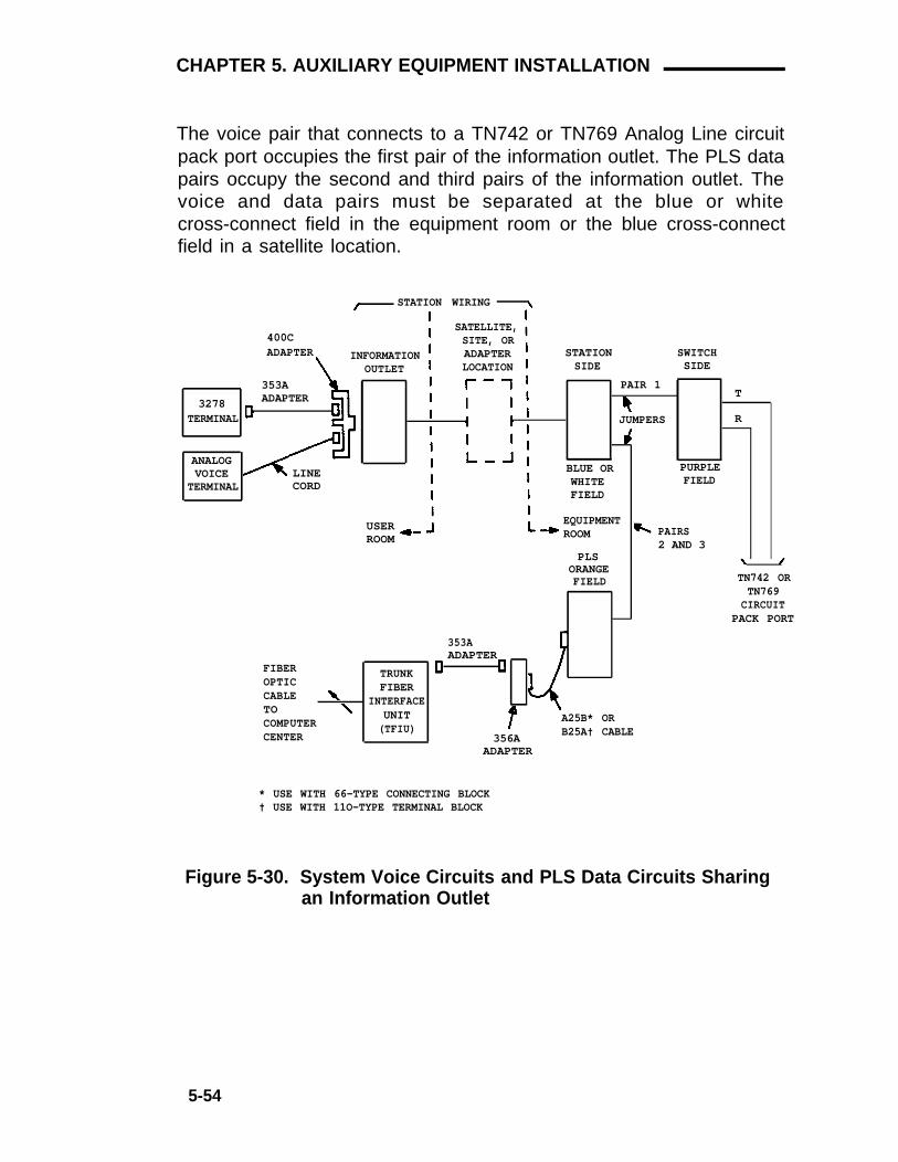
CHAPTER 5. AUXILIARY EQUIPMENT INSTALLATION
The voice pair that connects to a TN742 or TN769 Analog Line circuitpack port occupies the first pair of the information outlet. The PLS datapairs occupy the second and third pairs of the information outlet. Thevoice and data pairs must be separated at the blue or whitecross-connect field in the equipment room or the blue cross-connectfield in a satellite location.
STATION WIRING
400CADAPTER
SATELLITE,SITE, ORADAPTERLOCATION
INFORMATIONOUTLET
STATIONSIDE
SWITCHSIDE
353AADAPTER
PAIR 1
3278TERMINAL
T
RJUMPERS
ANALOGVOICE
TERMINALLINECORD
BLUE ORWHITEFIELD
PURPLEFIELD
USERROOM
EQUIPMENTROOM PAIRS
2 AND 3PLS
ORANGEFIELD TN742 OR
TN769CIRCUIT
PACK PORT
353AADAPTER
FIBEROPTICCABLETOCOMPUTERCENTER
TRUNKFIBER
INTERFACEUNIT(TFIU)
A25B* ORB25A† CABLE356A
ADAPTER
* USE WITH 66-TYPE CONNECTING BLOCK† USE WITH 11O-TYPE TERMINAL BLOCK
Figure 5-30. System Voice Circuits and PLS Data Circuits Sharingan Information Outlet
5-54

CHAPTER 5. AUXILIARY EQUIPMENT INSTALLATION
Installing Processor lnterface/EIA Port
The processor interface circuit pack (TN765) provides a single EIA portthat allows access to one data link. Figures 5-31 and 5-32 show directconnections and modem connections, respectively.
MAXIMUM*
PI/EIA CABLING DISTANCE PI/EIA50'
TN765 TN765CIRCUIT CIRCUITPACK PACK
SYSTEM 75 SYSTEM 75OR 75 XE OR 75 XE
* THE MAXIMUM DISTANCE LIMITATION FOR TWOSYSTEM 75/75 XE IS 50 FEET WHEN DIRECTLYCONNECTED WITH 24 AWG WIRE. REDUCING THEMAXIMUM DISTANCE MAY BE NECESSARY IFHIGHER GAUGE WIRE IS USED OR IF THECAPACITIVE LOAD ON THE LINE IS INCREASED.IN GENERAL, THE SYSTEM 75/75 XE SHOULDBE DIRECTLY CONNECTED BY THE SHORTESTPOSSIBLE CABLE.
Figure 5-31. Direct Connections for Processor Interface/EIA PortsBetween Two System 75s or 75 XEs
5-55

CHAPTER 5. AUXILIARY EQUIPMENT INSTALLATION
MAXIMUM*CABLING DISTANCE
50 FEET
M25B CORD
SAT
SYSTEM 75OR 75 XE
* THE MAXIMUM DISTANCE BETWEEN SYSTEM 75/75 XE IS50 FEET WHEN USING 24 AWG WIRE. THE DISTANCEMAY BE REDUCED IF HIGHER GAUGE WIRE IS USED ORIF THE CAPACITIVE LOAD ON THE LINE IS INCREASED.IN GENERAL, THE SAT AND THE SYSTEM 75/75 XESHOULD BE DIRECTLY CONNECTED BY THE SHORTESTPOSSIBLE CABLE.
Figure 5-32. Modem Connections for Processor Interface/EIA PortsBetween Two System 75s or 75 XEs
5-56

CHAPTER 6. GLOSSARY
CHAPTER 6. GLOSSARY
Note: A complete glossary for System 75 is contained in the AT&TSystem 75 Reference Manual—System Description, (555-200-200).
Asynchronous Data Transmission
A scheme for transmitting data where each character is preceded bya start bit and followed by a stop bit, thus permitting data elementsto occur at irregular intervals. This type transmission is advantageouswhen transmission is not regular (characters typed at a keyboard).
Asynchronous Data Unit (ADU)
A data communications equipment (DCE) type device that allowsdirect connection between RS-232C equipment and the digitalswitch.
Applications Processor (AP)
A minicomputer used to support several user-controlled applicationssuch as traffic analysis and electronic documentation.
Attendant Console
An electronic call-handling position with pushbutton control. Used byattendants to answer and place calls and to manage and monitorsome of the system operations.
Audio Information Exchange (AUDIX)
A unit that provides voice mail service to users.
Bridging
Thee sharing of the same extension by two or more voice terminals.
Central Office (CO)
The location housing telephone switching equipment that provideslocal telephone service and access to toll facilities for long-distancecalling.
6-1

CHAPTER 6. GLOSSARY
Central Office Trunk
A telecommunications channel that provides access from the switchto the public network through the local central office.
Channel
A communications path for transmitting voice and data.
Common Control Switching Arrangement (CCSA)
A private telecommunications network using dedicated trunks and ashared switching center for interconnecting company locations.
Console
See Attendant Console.
Data Channel
A communications path between two points used to transmit digitalsignals.
Data Communications Equipment (DCE)
The equipment on the network side of a communication Iink thatprovides all the functions required to make the binary serial datafrom the source or transmitter compatible with the communicationschannel.
Data Terminal Equipment (DTE)
Equipment comprising the source or sink of data, or both, that alsoprovides communication control functions (protocol). The DTE is anypiece of equipment at which a communications path begins or ends.
Digital Communications Protocol (DCP)
Defines the capability for providing simultaneous voice and datatransmission over the same channel.
6-2

CHAPTER 6. GLOSSARY
Digital Multiplexed Interface (DMI)
Specifies the remote interface requirements for multiplexed datacommunications between a host computer and a private switchingsystem.
Digital Trunk
A circuit in a telecommunications channel designed to handle digitalvoice and data.
Distributed Communications System (DCS)
A network of two or more switches, each with its terminals andtrunks, configured to function as a single large system.
Electronic Tandem Network (ETN)
A special tandem tie trunk network that has automatic call routingcapabilities based on the number dialed and most preferred routeavailable at the time the call is placed. Each switch in the network isassigned a unique private network office code (RNX), and each voiceterminal is assigned a unique extension number.
Enhanced Private Switched Communications Service (EPSCS)
A private telecommunications network that provides advanced voiceand data telecommunications services to companies with manylocations.
External Call
A connection between a system user and a party on the publictelephone network or on a tie trunk.
Facility
A general term used for the telecommunications transmissionpathway and associated equipment.
6-3

CHAPTER 6. GLOSSARY
Feature
Foreign Exchange (FX)
A specifically defined function or service provided by the switch.
A CO other than the one providing local access to the publictelephone network.
Foreign Exchange Trunk
A telecommunications channel that directly connects the switch to acentral office other than its local central office.
Ground-Start Trunk
On outgoing calls, the switch transmits a request for services to thedistant switching system by grounding the trunk ring lead. When thedistant system is ready to receive the digits of the called number,that system grounds the trunk tip lead. When the switch detects thisground, the digits are sent. (Tip and ring are common nomenclatureto differentiate between ground-start trunk leads.) On incomingcalls, detection of ground on the ring lead is sufficient to cause thecall to route to a predetermined destination, normally the systemattendant group. No digits are received.
Information Outlet
An 8-pin modular wall jack.
Interface
A common boundary between two systems or pieces of equipment.
Internal Call
A connection between two users within the switch.
Link
A transmitter-receiver channel or system that connects two locations.
6-4

CHAPTER 6. GLOSSARY
Loop-Start Trunk
After establishing a connection with the distant switching system foran outgoing call, the switch waits for a signal on the loop formed bythe trunk leads before sending the digits of the called number. Onincoming calls, the received request for service is sufficient to causethe call to route to a predetermined destination, normally the systemattendant group. No digits are received.
Main/Satellite/Tributary
A Main switch provides the following: interconnection, by tie trunks,with one or more subtending switches, called satellites; all attendantpositions for the main/satellite configuration; and, access to andfrom the public network. To a user outside the complex, amain/satellite configuration appears as a single switch, with a singlelisted directory number. A tributary is a switch, connected to themain by tie trunks, which has its own attendant position(s) and itsown listed directory number.
Modular Processor Data Module
See Processor Data Module.
Modular Trunk Data Module
See Trunk Data Module.
Modem Pooling
Provides shared-use conversion resources to eliminate the need fora dedicated modem when a data module accesses, or is accessedby, an analog line or trunk.
Multiplexer
A device for simultaneous transmission of two or more signals overa common transmission medium.
Network
An arrangement of inter- and/or intra-location circuits designed toperform a specific function.
6-5

CHAPTER 6. GLOSSARY
Off-Premises Terminal
An extension (analog only) connected from another location thatappears as a trunk circuit on any of the RJ21X network interfacesprovided by the local telephone company.
Out-of-Building Terminal
An extension not physically located in the same building as theequipment room but is located on the same property.
Paging Trunk
A telecommunications channel used to access an amplifier forloudspeaker paging.
Port
A designation of the location of a circuit that provides an interfacebetween the system and lines and/or trunks.
Private Network
A network used exclusively for handling the telecommunicationsneeds of a particular customer.
Processor Data Module (PDM)
Provides the required interface between the system and an EIAcomputer or data terminal.
Property Management System (PMS)
A stand-alone computer that lodging and health service organizationsuse for services such as reservations, housekeeping, billing, etc.
Public Network
The network that can be openly accessed by all customers for localor long-distance calling.
6-6

Riser Cable
A cable run vertically from the equipment room to the various floorsof a building.
Satellite
CHAPTER 6. GLOSSARY
A physical location (closet) where cross-connect administration cantake place and adjunct power may be applied.
Single-Line Voice Terminals
Voice terminals served by a single-line tip and ring circuit.
Site
A physical location (closet) for pass-through connections whereadjunct power may be applied.
Software
A set of computer programs that accomplish one or more tasks.
Standard Serial Interface (SSI)
A communications protocol developed by AT&T TeletypeCorporation for use with the 500 Business Communications Terminaland the 400-series printers.
Station Cable
Any cable run from the equipment room, a site or satellite location,or adapter to the information outlets.
Tandem Switch
A switch within an ETN that provides the logic to determine the bestroute for a network call, possibly modifies the digits outpulsed, andallows or denies certain calls to certain users.
6-7

CHAPTER 6. GLOSSARY
Tandem Tie Trunk Network (TTN)
A private network that interconnects several customer switchingsystems by dial repeating tie trunks. Access to the various systemsis dictated by codes that must be individually dialed for each system.
Telephone
An analog 500-, 2500-, or 7102-type voice instrument.
Tie Trunk
A telecommunications channel that directly connects two privateswitching systems.
Trunk
A telecommunications channel between two switching systems.
Trunk Data Module (TDM)
Provides the required interface between the switch and a data set(modem) or data service unit connected to a private or switched dataline.
Trunk Group
Telecommunications channels assigned as a group for certainfunctions.
Voice Terminal
A single-line or multi-appearance digital or hybrid voice instrument.
6-8

CHAPTER 7. INDEX
CHAPTER 7. INDEX
110A-Type Hardware, 2-7
110A-Type Terminal Blocks, WallMounting, 3-25
110P-Type Hardware, 2-11
110P-Type Terminal Blocks, FrameMounting, 3-28
110P-Type Terminal Blocks, WallMounting, 3-25
110-Type Designation Strip, 3-34
110-Type Designation Strips, 2-22
110-Type Hardware, 2-3
110-Type Hardware at Satellite Locations,Installing, 4-4
110-Type Hardware Requirements, 3-22
110-Type Hardware Tools, 2-21
110-Type Patch Cord, 2-18
110-Type Terminal Insulator, F Clip, 2-22
110-Type Wiring Blocks, 2-3
1.544 Mbps Digital Service Interface, 2-34
157B Connecting Block, 2-24
16-Port Analog Line Board Adapter Cable, 853BAdapter, 2-45
183-Type Backboards, 2-26
187B1 Backboard, 2-28
188-Type Backboards, 2-18
1-Point Administration, 4-23
258A Adapter, 3-95
25-Pair Station Cable Sizing, 3-109
278A Paging Adapter, Loudspeaker PagingAccess, Installing, 5-5
2-Point Administration, 4-24
3270 Data Modules, Installing, 5-33
356A Adapter, 3-96
3-Pair Blue Station Labels, 3-47
3-Pair Station Cable Circuits, 3-109
3-Pair to 4-Pair Station Circuits, 3-102
3-Pair White Station Labels, 3-45
4-Pair Blue Station Labels, 3-49
4-Pair Station Cable Circuits, 3-110
4-Pair Station Cable, Sizing, 3-108
4-Pair Station Circuits, 3-99
4-Port MET Line Board ConcentratorCable, 2-46
574-5 Power Transfer Unit, 2-37
574-5 Power Transfer Unit and Control CarrierOutputs Label, 3-40
574-5 Power Transfer Unit, Installing the, 4-41
574-5 Power Transfer Unit Label, 3-43
575-4 Sneak Current Fuse Panel, 2-34
66M1-50 Connecting Block, 2-23
66-Type Connecting Blocks,Connectorized, 2-24
66-Type Connecting Blocks, MultipleMounted, 2-25
66-Type Hardware at Satellite Locations,Installing, 4-9
66-Type Hardware Description, 2-23
66-Type Hardware Requirements, 3-24
66-Type Hardware Tools, 2-30
66-Type/110-Type Hardware Equipment RoomApplications, 3-1
853B Adapter, 2-45
89A Control Unit, Loudspeaker Paging Access,Installing, 5-8
A
Adapter258A, 3-95356A, 3-96BR2580A, 3-95ZD8AJ, 3-97
7-1

CHAPTER 7. INDEX
Adapter Requirements, 3-108
Adjunct Power Units, 2-47
Adjunct Power Units, Bulk Power Supply, 2-49
Adjunct Power Units, Individual PowerSupplies, 2-47
Adjunct Powering, 4-12
Adjunct Powering From InformationOutlets, 4-16
Adjunct Powering From Site Locations, 4-14
Adjunct Powering From the Equipment Roomand Satellite Locations, 4-12
ADU, Installing, 5-45
Alarm, Customer-Provided, Installing, 4-34
Announcement, Audichron Wake-Up System,Installing, 5-28
Announcement, Recorded Digital Announcer,Installing, 5-26
Announcement, Recorded Equipment,Installing, 5-22
AP Interface, Installing, 5-39
Associated Hardware, 2-31
Asynchronous Data Units, Installing, 5-45
Attendant Console, Installing, 4-24
Audichron Wake-Up Announcement System,Installing, 5-28
Audio Information Exchange Interface,Installing, 5-42
AUDIX Interface, Installing, 5-42
Auxiliary Circuit and Control Carrier OutputsLabel, 3-36
Auxiliary Equipment Description, 5-1
Auxiliary Equipment Installation, 5-1
Auxiliary Labels, Yellow, 3-35
Auxiliary Port and Circuit Label, 3-35
B
Backboard, 187B1, 2-28
Backboards, 183-Type, 2-26
Backboards, 188-Type, 2-18
Background Music, Loudspeaker Paging,Installing, 5-20
Blank Auxiliary Label, 3-44
Blue 3-Pair Station labels, 3-47
Blue 4-Pair Station labels, 3-49
Blue Station Labels, 3-45
BR2580A Adapter, 3-95
Bridging Clips, 2-30
Bulk Power Supply, 2-49
C
Cabinet to Cross-Connect Field, CableRouting, 3-73
Cable Installation, 3-64
Cable Labels, 3-64
Cable Routing From Cabinet to Cross-ConnectField, 3-73
Cable Routing Guidelines, 3-66
Cable Slack Manager Installation, 3-32
Cable Slack Manager Requirements, 3-21
Cable Slack Manager, Z113A Housing, 2-33
Cable Slack Manager, Z114A Housing, 2-33
Cable Slack Managers, 2-31
CablesStation, 3-92
Call Management System Interface,Installing, 5-42
Closets, 3-95
CMS Interface, Installing, 5-42
CO Trunk Label, Green, 3-34
Colocated DS1 Tie Trunks, Installing, 4-33
Concentrator Cable, WP-90929, List 1, 2-39
Concentrator Cable, WP-90929, List 2, 2-42
Concentrator Cable, WP-90929, List 3, 2-43
Concentrator Cable, WP-90929, List 4, 2-45
Concentrator Cables For Use With 110-TypeHardware, Selecting, 3-77
Concentrator Cables For Use With 66-TypeHardware, Selecting, 3-81
7-2

CHAPTER 7. INDEX
Connecting Block, 66M1-50, 2-23
Connecting Blocks, 2-4
Connecting Blocks, Connectorized66-Type, 2-24
Connecting Blocks, Multiple-Mounted66-Type, 2-25
Connecting Control Carrier Outputs Cable, 3-77
Connecting Trunk Pairs to the Switch CabinetUsing Concentrator Cables, 3-81
Connecting Trunk Pairs to the Switch CabinetUsing Jumper Wires To Establish 3-PairModularity, 3-84
Connector Cables Between Cross-ConnectField and Auxiliary Cabinet, Installing, 3-90
Connector Cables Between Switch Cabinet andCross-Connect Field Installing, 3-90
Connectorized 66-Type ConnectingBlocks, 2-24
Console, Attendant Installing, 4-24
Console, Selector Installing, 4-29
Control Carrier Cable (Used With 110-TypeHardware), Labeling, 3-77
Control Carrier Cable (Used With 66-TypeHardware),Labeling, 3-77
Control Carrier Outputs Cable, Connecting, 3-77
Control Carrier Outputs Cable Installation, 3-75
Coupled Bonding Conductor (CBC) Grounding,Installing, 3-87
Cross-Connect Field and Auxiliary CabinetConnector Cables, Installing, 3-90
Cross-connect Field, Equipment Room, 4-20
Cross-Connect Field Installation, 3-25
Cross-Connect Field Installation, FrameMounting 110P-Type, 3-28
Cross-Connect Field Installation, Wall Mounting110A-Type, 3-25
Cross-Connect Field Installation, Wall Mounting110P-Type, 3-25
Cross-Connect Field Labeling, 3-32
Cross-Connect Field Labeling, 66-TypeConnecting Blocks, 3-58
Cross-Connect Hardware 110-Type, 2-3
Cross-Connect Hardware, 66-Type, 2-23
Cross-Connect Hardware Selection, 1-8
Customer-Provided Alarm, Installing, 4-34
Customer-Provided Terminal, ADU,Installing, 5-45
DData Modules, 3270 Installing, 5-33
DCS, Installing, 5-43
Designation Strip, 3-34
Designation Strips, 2-22
Dial Dictation Equipment, Installing, 5-32
Dictation Equipment, Dial, Installing, 5-32
Digital Announcer, Installing, 5-26
Distribution Field, 3-4
Distribution Field (110-Type Hardware Only), 3-5
Distribution Field (66-Type Hardware Only), 3-11
DS1 Tie Trunks, Installing, 4-32
Dual-Purpose Emergency Transfer StationLabels, 3-56
E
Emergency Transfer, Dual-Purpose StationsLabels, 3-56
Emergency Transfer Unit, Z1A, 2-37
Emergency Transfer Unit, Z1A, Installingthe, 4-50
Emergency Transfer Units, 2-37
Emergency Transfer Units, Installing, 4-40
Emergency Transfer Voice Terminals,Installing, 4-40
Equipment, Auxiliary, Description, 5-1
Equipment, Auxiliary, Installation, 5-1
Equipment Requirements, 3-21
Equipment Requirements, 110-TypeHardware, 3-22
Equipment Requirements, 66-TypeHardware, 3-24
Equipment Requirements, Cable SlackManager, 3-21
7-3

CHAPTER 7. INDEX
Equipment Requirements, Patch Cord, 3-22
Equipment Room and Satellite LocationsAdjunct Powering, 4-12
E q u i p m e n t R o o m A p p l i c a t i o n s ,66-Type/110-Type Hardware, 3-1
Equipment Room Cross-Connect Field, 4-20
Equipment Room Floor Plans, 3-13
Equipment Room Hardware and CablingInstallation, 3-25
Equipment Room Station CircuitDistribution, 3-99
External Ringing, Installing, 4-63
F
F Clip Terminal Insulator, 2-22
F-61789 Power Adapter Cord, 2-20
FCC Registered Music Source, Installing, 5-19
FCC Registered Recorded AnnouncementEquipment, Installing, 5-25
Floor Plans, Equipment Room, 3-13
Frame Mounting 110P-Type TerminalBlocks, 3-28
G
Green CO Trunk Label, 3-34
Grounding, Coupled Bonding Conductor (CBC),Installing, 3-87
H
Hardware ChangesWiring, 1-9
Hardware Satellite LocationRequirements, 3-108
Hardware Selection, Cross-Connect, 1-8
IINADS Interface, Installing, 4-30
Index Strips, 2-4
Individual Power Supplies, 2-47
Information Outlets, 3-92Adjunct Powering, 4-16
Information Outlets, Installing, 4-10
Information Outlets Locations, 3-108
Information System Network Interface,Installing, 5-49
Initialization and Administration SystemInterface, Installing, 4-30
Installation and Administration, Jumper, 4-18
Installation and Administration, PatchCord, 4-18
Installation—FCC Registered MusicSource, 5-19
Installation—Non-FCC Registered Music Source,5-19
Installing 3270 Data Modules, 5-33
Installing AP Interface—AT&T System 75Only, 5-39
Installing Attendant Console, 4-24
Installing Audichron Wake-Up AnnouncementSystem—R1V3 Only, 5-28
Installing AUDIX Interface—V3 Only, 5-42
Installing CMS Interface—V3 Only, 5-42
Installing Colocated DS1 Tie Trunks, 4-33
Installing Customer-Provided Terminal UsingADUs, 5-45
Installing Dial Dictation Equipment, 5-32
Installing Distributed Communications System(DCS)—V2 and V3, 5-43
Install ing Emergency Transfer Units andAssociated Voice Terminal, 4-40
Installing External Ringing, 4-63
Install ing FCC Registered RecordedAnnouncement Equipment, 5-25
Installing Information Outlets, 4-10
Installing ISN Interface, 5-49
Installing Loudspeaker Paging, 5-3
Installing Loudspeaker Paging Access—278APaging Adapter, 5-5
Installing Loudspeaker Paging Access—89AControl Unit, 5-8
Installing Loudspeaker Paging With BackgroundMusic, 5-20
7-4

CHAPTER 7. INDEX
Installing Music-on-Hold, 5-3
Installing Music-on-Hold Access, 5-16
Install ing Non-FCC Registered RecordedAnnouncement Equipment, 5-25
Installing PagePac 20, 5-11
Installing PagePac 50/100/200, 5-14
Installing PagePac VS, 5-13
Installing PagePac® Paging System, 5-11
Installing Patch Cords/Jumper Wires, 4-20
Installing PMS Interface—V3 Only, 5-44
Installing Premises Lightwave System (PLS)Interface, 5-53
Installing Processor Data Modules (PDMs), 5-36
Installing Queue Warning Indicator, 4-64
Installing Recorded AnnouncementEquipment, 5-22
Installing SMDR Interface, 5-45
Installing Sneak Fuse Panels, 3-63
Installing STARLAN NETWORK Interface, 5-52
Installing Station Cables, 4-1
Installing the Cable Slack Managers, 3-32
Installing the Z1A Emergency TransferUnit, 4-50
Installing Trunk Cables Between NetworkInterface, Sneak Fuse Panel, and SwitchCabinet, 3-77
Introduction, 1-1
ISN Interface, Installing, 5-49
JJumper Installation and Administration, 4-18
Jumper Wire, 2-21
Jumper Wires, Installing, 4-20
Jumper Wires, Removing, 4-22
LLabel, 3-Pair Blue Station, 3-47
Label, 3-Pair White Station, 3-45
Label, 4-Pair Blue Station, 3-49
Label, 574-5 Power Transfer and Control CarrierOutputs, 3-40
Label, 574-5 Power Transfer Unit, 3-43
Label, Auxiliary and Control Carrier Outputslabel, 3-36
Label, Auxiliary Port and Circuit, 3-35
Label, Blank Auxiliary, 3-44
Label, Blue Station, 3-45
Label, Cables, 3-64
Label, Dual-Purpose Emergency TransferStations, 3-56
Label, Green CO Trunk, 3-34
Label, Purple Port, 3-52
Label, System Trunk and Tie Trunk Port, 3-55
Label, White Station, 3-45
Label, Yellow Auxiliary, 3-35
Label, Z1A Emergency Transfer and ControlCarrier Outputs, 3-38
Label, Z1A Emergency Transfer Unit, 3-42
Labeling, 110-Type Designation Strip, 3-34
Labeling 110-Type Terminal Blocks, 3-32
Labeling 66-Type Connecting Blocks, 3-58
Labeling Control Carrier Cable (Used With110-Type Hardware), 3-77
Labeling Control Carrier Cable (Used With66-Type Hardware), 3-77
Labeling, Cross-Connect Field, 3-32
Labeling, Cross-Connect Field, 66-TypeConnecting Blocks, 3-58
Labeling, Satellite Location (110-TypeHardware), 4-5
Labeling, Satellite Location (66-TypeHardware), 4-9
Layout, 3-108
Loudspeaker Paging Access, 278A PagingAdapter, Installing, 5-5
Loudspeaker Paging Access, 89A Control Unit,Installing, 5-8
Loudspeaker Paging, Installing, 5-3
Loudspeaker Paging, PagePac 20,Installing, 5-11
7-5

CHAPTER 7. INDEX
Loudspeaker Paging, PagePac 50/100/200,Installing, 5-14
Loudspeaker Paging, PagePac VS,Installing, 5-13
Loudspeaker Paging With Background Music,Installing, 5-20
M
MET Set AdapterZD8AJ, 3-97
Miscellaneous Wiring lnstallation, 4-24
Multiple 25-Pair Station Cable Sizing, 3-109
Multiple-Mounted 66-Type ConnectingBlocks, 2-25
Music-on-Hold Access, Installing, 5-16
Music-on-Hold, lnstalling, 5-3
N
Network Interface and Switch Cabinet TrunkCables, Installing, 3-77
Network Interface, RJ21X, 2-34
Network Interface, RJ2GX, 2-34
Network Interfaces, 2-34
Non-FCC Registered Music Source,Installing, 5-19
Non-FCC Registered Recorded AnnouncementEquipment, lnstalling, 5-25
O
Off-Premises Voice Terminal Wiring,Installing, 4-35
Organization, 1-3
Out-of-Building Terminal WiringInstallation, 4-36
PPagePac 20, Installing, 5-11
PagePac 50/100/200, Installing, 5-14
PagePac Paging System, Installing, 5-11
PagePac VS, Installing, 5-13
Paging Access, Loudspeaker 278A Adapter,Installing, 5-5
Paging Access, Loudspeaker 89A Control UnitInstalling, 5-8
Paging, Loudspeaker Installation, 5-3
Paging, Loudspeaker PagePac 20,Installing, 5-11
Paging, Loudspeaker PagePac 50/100/200,Installing, 5-14
Paging, Loudspeaker PagePac Paging System,Installing, 5-11
Paging, Loudspeaker PagePac VS,Installing, 5-13
Paging, Loudspeaker With Background Music,Installing, 5-20
Patch Cord, 110-Type, 2-18
Patch Cord Installation and Administration, 4-18
Patch Cord Requirements, 3-22
Patch Cords, Installing, 4-20
Patch Cords, Removing, 4-22
PDMs, Installing, 5-36
Planning, 1-10
PLS Interface, Installing, 5-53
PMS Interface—V3 Only, Installing, 5-44
Port Labels, Purple, 3-52
Power Adapter Cord, F-61789, 2-20
Power Adapter Cord Installation, 4-23
Power Adapter Cord Removal, 4-23
Power Adapter Cords, 2-28
Power Transfer Unit, 574-5, 2-37
Power Transfer Unit, 574-5, Installing, 4-41
Processor Data Modules, Installing, 5-36
Property Management System Interface,Installing, 5-44
Purple Port Labels, 3-52
QQueue Warning Indicator, Installing, 4-64
7-6

CHAPTER 7. INDEX
R
Recorded Announcement, Digital Announcer,Installing, 5-26
Recorded Announcement Equipment,Installing, 5-22
Recorded Telephone Dictation Equipment,Installing, 5-32
Removing Patch Cords/Jumper Wires, 4-22
RJ21X Network Interface, 2-34
RJ2GX Network Interface, 2-34
Routing Cable Guidelines, 3-66
Routing Cables From Cabinet to Cross-ConnectField, 3-73
Routing Cables Using 110-Type TerminalBlocks, 3-67
Routing Cables Using 66-Type ConnectingBlocks, 3-70
S
Satellite Location, Labeling (110-TypeHardware), 4-5
Satellite Location, Labeling (66-TypeHardware), 4-9
Satellite Location RequirementsHardware, 3-108
Satellite Locations, 3-98110-Type Hardware, Installing, 4-4
Satellite Locations, 66-Type Hardware, Installing,4-9
Satellite Locations Using 110-TypeHardware, 3-98
Satellite Locations Using 66-TypeHardware, 3-98
Selecting Concentrator Cables For Use With110-Type Hardware, 3-77
Selecting Concentrator Cables For Use With66-Type Hardware, 3-81
Selector Console, Installing, 4-29
Site Locations, 3-95Adjunct Powering, 4-14
SMDR Interface, Installing, 5-45
Sneak Current Fuse Panel, 575-4, 2-34
Sneak Fuse Panel, 2-34
Sneak Fuse Panel Installation, 3-63
STARLAN NETWORK Interface, Installing, 5-52
Station Cable25-Pair Sizing, 3-1094-Pair Sizing, 3-108Multiple 25-Pair Sizing, 3-109
Station Cable Circuits3-Pair, 3-1094-Pair, 3-110
Station Cable, Installing, 4-1
Station Cables, 3-92
Station Circuit Distribution From EquipmentRoom, 3-99
Station Circuits3-Pair to 4-Pair, 3-1024-Pair, 3-99
Station Labels 3-Pair, Blue, 3-47
Station Labels 3-Pair, White, 3-45
Station Labels 4-Pair, Blue, 3-49
Station Labels, Blue, 3-45
Station Labels, White, 3-45
Station Wiring and Associated HardwareInstallation, 4-1
Station Wiring Design, 3-91
Switch Cabinet and Cross-Connect FieldConnector Cables, Installing , 3-90
Switch Cabinet Trunk Pairs Connection, UsingJumper Wires, 3-84
System Trunk and Tie Trunk Port Labels, 3-55
T
Terminal Wiring, Out-of-BuildingInstallation, 4-36
Test Cord, 2-21
Tie Trunks, DS1 Installing, 4-32
Tools, 110-Type Hardware, 2-21
Tools, 66-Type Hardware, 2-30
Trunk and Tie Trunk Port, System Labels, 3-55
Trunk Cables Between Network Interface andSystem Cabinet, Installing, 3-77
7-7

CHAPTER 7. INDEX
Trunk Concentrator Cables, 2-39
T r u n k P a i r s t o S w i t c h C a b i n e t U s i n gConcentrator Cables, Connecting, 3-81
Trunk Pairs to Switch Cabinet Using JumperWires, Connecting, 3-84
Trunk/Auxiliary Field, 3-1
Typical Cross-Connect Field Using 110-TypeHardware, 3-16
Typical Cross-Connect Field Using 66-TypeHardware, 3-20
Typical Floor Plans, 3-13
V
Voice Terminal Wiring, Off-Premises,Installing, 4-35
Voice Terminals, Emergency Transfer,Installing, 4-40
W
Wake-Up Announcement System, Audichron,Installing, 5-28
Wall Mounting 110A-Type Terminal Blocks, 3-25
Wall Mounting 110P-Type Terminal Blocks, 3-25
Wall Mounting 66-Type Connecting Blocks, 3-30
Wall Space Requirements, 3-20
Wall Space Requirements for 110-TypeHardware, 3-21
Wall Space Requirements for 66-Type Hardware,3-21
White 3-Pair Station labels, 3-45
White Station Labels, 3-45
Wiring Blocks, 110-Type, 2-3
Wiring Hardware Changes, 1-9
WP-90929, List 1 Cable Assembly, 2-39
WP-90929, List 2 Cable Assembly, 2-42
WP-90929, List 3 Concentrator Cable, 2-43
WP-90929, List 4 Concentrator Cable, 2-45
YYellow Auxiliary Label, 3-35
ZZ1A Emergency Transfer Unit, 2-37
Z1A Emergency Transfer Unit and ControlCarrier Outputs Label, 3-38
Z1A Emergency Transfer Unit, Installingthe, 4-50
Z1A Emergency Transfer Unit Label, 3-42
ZD8AJ Adapter, 3-97
7-8