attachment atmospheric relief valve area heatup calculations · devonrue calculation project no....
TRANSCRIPT
RG&E Answers To The NRC's March 21, 1991 Station Blackout Questions
Attachment 2Atmospheric Relief Valve Area
Heatup Calculations
9104300401 910422PDR ADOCK 05000244P PDF<
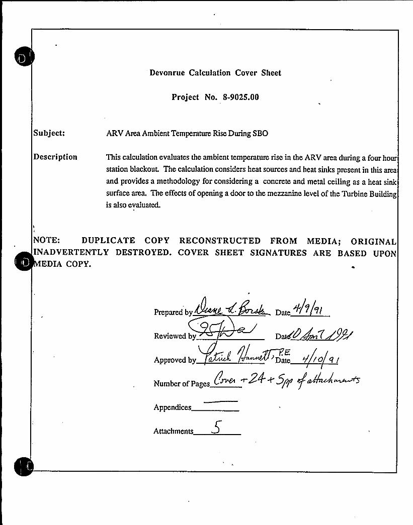
Devonrue Calculation Cover Sheet
Project No. 8-9025.00
Subject: ARVArea Ambient Temperature Rise During SBO
Description This calculation evaluates the ambient temperature rise in the ARV area during a four hour
station blackout. The calculation considers heat sources and heat sinks present in this atria
and provides a methodology for considering a concrete and metal ceiling as a heat sink
surface area. The effects of opening a door to the mezzanine level of the Turbine Buildingis also evaluated.
NOTE: DUPLICATE COPY RECONSTRUCTED FROM MEDIA; ORIGINALINADVERTENTLY DESTROYED. COVER SHEET SIGNATURES ARE BASED UPON
EDIA COPY.
Prepared by
Reviewed by @WC
.EApproved by ~~~ Date
Numberof Pages ~~ ~/Y fAppendices
Attachments
Devonrue Calculation Project No. 8-9025.00Date: April9, 1991
Page 1 of 24
Subject: Ginna Atmospheric Relief Valve (ARV) Area Ambient Temperature Rise-Revised Methodology
No computer calculations have been utilized in this analysis. Excel spreadsheets have been utilizedin the calculation of surface temperatures of insulated piping and in the calculation of total heat
generated from hot surfaces. However, the formulas are provided in this calculation and a
numerical check has been made of the accuracy of the spreadsheet calculations.
1. The perimeter of the Intermediate Building is assumed to be as shown on Ginna StationDrawing 33013-2121, Rev. 0
2. The normal max. ambient temperature in the Intermediate Building is assumed to be 104'F,consistent with the NUMARC87-00 Section 7 methodology and the maximum auxiliarybuilding temperature listed in Ginna FSAR Table 3.11-1.
The normal maximum ambient temperature of the Containment Structure just adjacent to the
South wall of the Intermediate Building is assumed to be 120'F as stated in Ginna FSARTable 3.11-1.
The South wall of the ARV area is assumed to be poured concrete as shown on GinnaStation drawing 330103-2121, Rev. 0. The North, East, and West walls of the ARV area
(the northern portion of the Intermediate Building) are solid concrete block as shown onGinna Station drawing 330103-2121, Rev. 0. The walls are assumed to behave in a
similar manner to poured concrete walls and willbe treated similarly in this calculation.
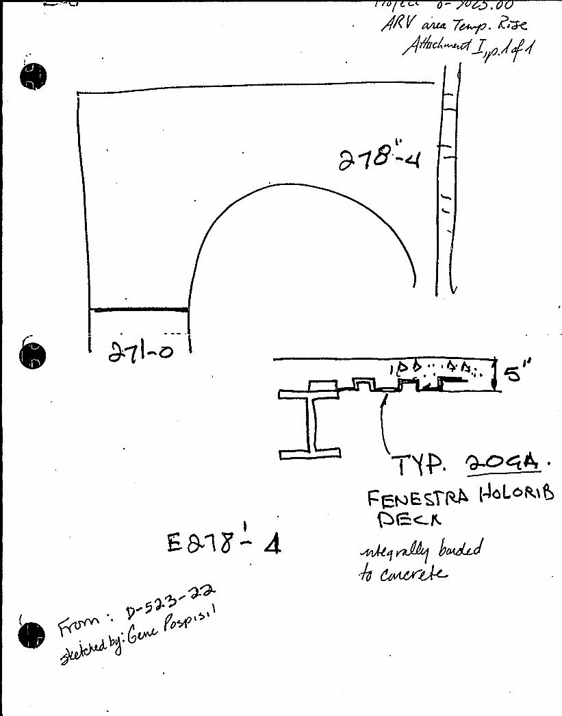
5. The ceiling of the ARV area is 5" thick pouted concrete, integrally bonded with 20 gaugefenestra holorib decking as shown on sketch D-523-22 and reproduced on Attachment 1.
The calculation willtn:at this construction as 5" of concrete with an inside layer of0.036"of steel and willuse the thermal properties of steel and concrete reported in the ASHRAEhandbook of fundamentals.
Devonrue Calculation Project No. 8-9025.00Date: April9, 1991
Page 2 of24
Subject: Ginna Atmospheric Relief Valve (ARV) Area Ambient Temperature Rise-Revised Methodology
6. Thermal insulation on piping is assumed to be of the type and thickness defined in RG&ESpecification ME-269, Revision 0.
7. Heating Steam piping and equipment is conservatively assumed to be normally operating at
a temperattue of220'F.
8. Under SBO conditions, immediately following reactor trip and MSIV closure, only one
Safety Relief Valve on each steam header willliftto remove decay heat as described inGinna UFSAR Section 7.4.1.3. Once the operators are using the ARVs to remove decayheat, it is assumed that only one ARV willbe operating. Ginna UFSAR section 7.4.1.3states, "One.atmospheric steam dump, which can be operated from the Control Room is
sufficient for maintaining hot shutdown or to achieve cooldown of the reactor coolantsystem below hot shutdown conditions."
9. The ARVs ate assumed to be actuated early enough to allow SRV tailpipe cooldown withinthe first hour of the event.
Any additional assumptions are noted in the body of the calculation.
1. NUMARC 87-00, "Guidelines and Technical Bases for NUMARCInitiatives AddressingStation Blackout at Light Water Reactors," including Appendix E, Appendix F and the
Appendix F Topical Report, November 1987.
2. RG&E Technical Specification, ME-269, "Pipe, Duct, and Equipment Insulation, GinnaStation," draft issue Revision 0, dated January 30, 1989.
3. Ginna Station Plant Arrangement Drawing No. 33013-2121, Rev. 0, Cont Structure &Intermediate Bldg Plan - Oper. Flr. El. 278'-4" & 274'-6".
4. Ginna Station Plant Arrangement Drawing No. 33013-2129, Rev. 0, Intermediate BldgPlans Above Elev's.293'-0", 298'-4", & 315'-4".

Devonrue Calculation Project No. 8-9025.00Date: April9, 1991
Page 3 of 24
Subject: Ginna Atmospheric Relief Valve (ARV) Area Ambient Temperature Rise-Revised Methodology
5. Ginna Station PAID Drawing No, 33013-1231, Rev. 13, Main Steam
6. Ginna Station P&IDDrawing No. 33013-1915, Rev.4, Heating Steam
7. Ginna UFSAR Table 3.11-1, "Environmental Service Conditions for Equipment Designed
to Mitigate Design-Basis Events."
8. Ginna UFSAR Section 7.4.1.3, Revision 4, dated December, 1988
9. ASHIME 1985 Handbook of Fundamentals, Chapter 39, Table 3, "Properties of Solids"
10. Kreith, Frank, and William Black, B i H Tr n f r, 1980.
11. Incropera, Frank P, and David P. DeWitt, In n H Tr n f r,1979.
The objective of this calculation is to determine the ambient temperature rise in the ARVatria duringa four (4) hour SBQ-induced loss of ventilation. This calculation uses a modification of the
NUMARC87-00 section 7 methodology that accounts for the ARVama ceiling as a heat sink. Thesection 7 methodology is based on the assumption that pored concrete walls willact as heat sinksand that their surface temperatures remain essentially constant over the course of the 4 hourduration. However, the constant temperature assumption may not be valid for the ceiling because
the ceiling is not as thick and has a different construction from the concrete walls. Therefore, the
temperature rise in this surface must be considered ifcrediting it as a heat sink, the simplifiedmethodology provided in NUMARC87-00, section 7, cannot be applied ditectly.
In considering the surface temperature rise in the ceiling from heat generated within the ARV room,the heat input to this ceiling from the atea above it is also accounted for.
The temperature of the ceiling after 4 hours is calculated by performing an energy balance:
Devonrue Calculation Project No. 8-9025.00Date: April9, 1991
Page 4 of 24
Subject: Ginna Atmospheric Relief Valve (ARV) Area Ambient Temperature Rise-Revised Methodology
Q = rho cp U dT/dt, where
Q = heat generation rate
rho = density of the heat sink material
cp is the speciflc heat at constant pressure of the heat sink material
dT/dt = the temperatute change of the wall per unit time, or for this case;
(T flnal - T initial)/4 hours
Once the surface temperature rise is computed for the ceiling, itwillbe considered in the simplified
NUMARC87-00 equation as follows:
Tair = Tw + [Q/A] 3/4 where
Tair = the resultant ambient air temperature in the ARVarea;
Tw = the wall temperature after 4 hours computed as a weighted average of each
wall or ceiling prorated on the basis of surface atea;
Q = heat generation rate;"
A = the total surface area of walls and ceilings acting as heat sinks.
The following steps shall be performed to accomplish the described method for determining the
ARVarea temperanue:
1. Conservatively estimate the heat generation rate, Q, in the ARV area and in the room
above. The heat generation rate willbe calculated by considering heat rejected from hot
piping and equipment and using the methodology supplied in NUMARC 87-00,- Section 7.
2. Calculate the surface area of each wall and ceiling acting as a heat sink and determine
the proportion represented by each.
3. Using flat plate heat transfer correlations, the amount ofheat transferred into the ceiling
from the area above the ARV area willbe calculated. The amount of heat transferred
from the ARVarea willbe calculated based on the proportion of total heat sink surface
area in the ARV room represented by the ceiling
0',
Devonrue Calculation Project No. 8-9025.00Date: April9, 1991
Page 5 of 24
'ubject:Ginna Atmospheric Relief Valve (ARV) Area Ambient Temperature Rise-Revised Methodology
4. Determine the ceiling temperature after four hours using the equation
Q = rho cp V dT/dt. The density and specific heat of the composite concrete/steel
structure willbe considered in this determination. The calculated ceiling temperature
after four hours of heating will be conservatively assumed throughout the station
blackout transient for the purposes ofcalculating ARVarea temperature.
5. Determine the wall temperature Tw for use in the equation
Tair = Tw + I,Q/A] / .
6. Determine the ARV room temperature after 4 hours using the above equation.
7. Consider the effects of opening doors using the relationship defined in Section 7 ofNUMARC87-00.
Step 1: Determine the heat generation rate, Q, in the ARV area and in the
area above.
The major heat souice in each of these areas is hot piping and equipment. A physical inspection ofeach area was performed to identify the relevant heat sources and define their characteristic
dimensions such as diameter and length. In the case of insulated surfaces, the surface temperatures
must be calculated. As stated in the assumptions section, the insulation type and thickness is
assumed to be as specified in ME-269, Table 1, except in the case of the HHCC Tank where the
insulation thickness was field measured. In accordance with ME-269, all insulation is treated as
calcium silicate.
The surface temperature is calculated by considering the convective heat transfer between the
insulated surface and the air:
q = h A dT = h (Ts - T ) 2 z rs I„
where h is the unit thermal surface conductance (Btu/hr. sq ft 'F), rs is the radius of the insulated
surface, 1 is the pipe length, Ts is the insulated surface temperature, and T~ is the ambient air
temperature
Devonrue Calculation Project No. 8-9025.00Date: April9, 1991
Page 6 of 24
Subject: Ginna Atmospheric Relief Valve (ARV) Area Ambient Temperature Rise-Revised Methodology
t T.
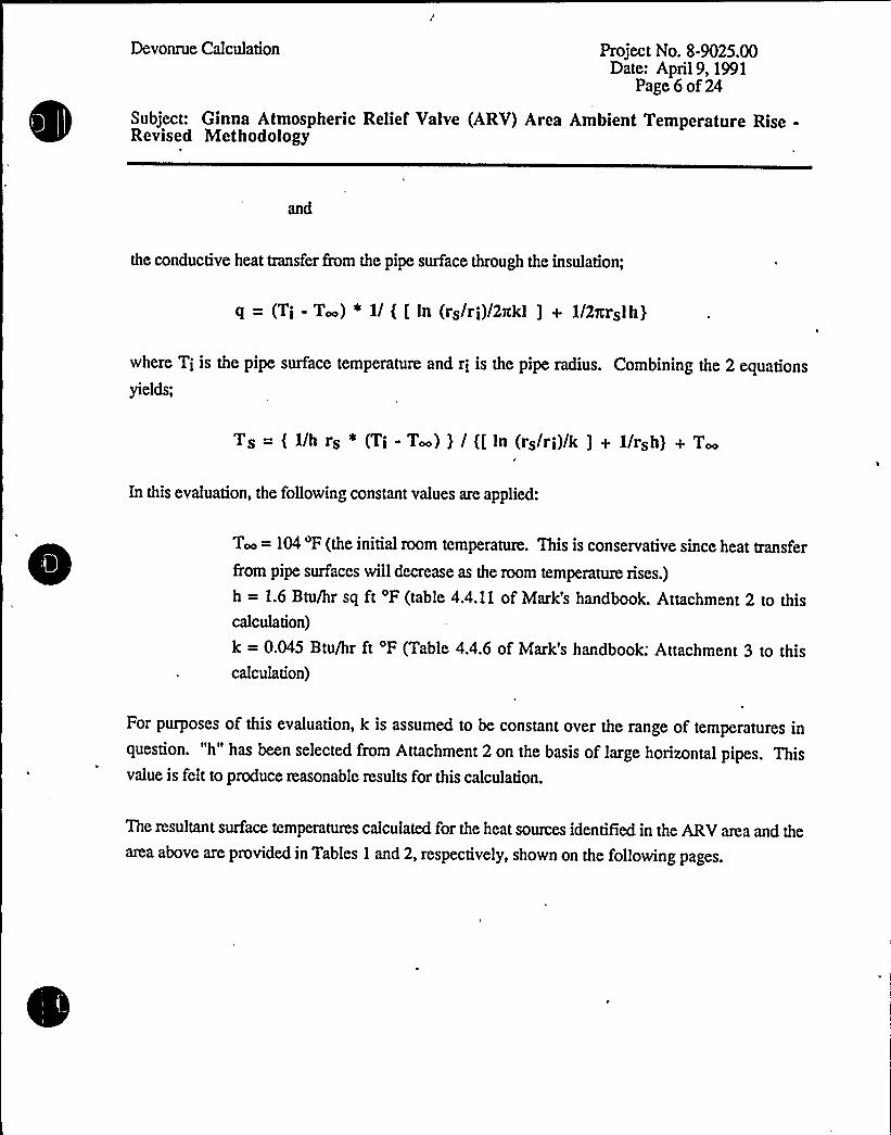
the conductive heat transfer from the pipe surface through the insulation;
q = (Ti - T~) * 1/ ( [ In (rs/ri)/2nkl ] + 1/Zxrslh}
where Ti is the pipe surface temperature and ri is the pipe radius. Combining the 2 equations
yields;
Ts = ( 1/h rs * (Ti - T~) ) / ([ In (rs/ri)/k ] + 1/rsh) + T~
In this evaluation, the followingconstant values are applied:
T~ = 104 'F (the initial room temperature. This is conservative since heat transfer
from pipe surfaces willdecrease as the room temperature rises.)
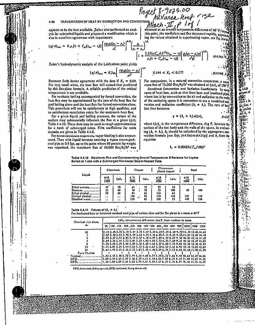
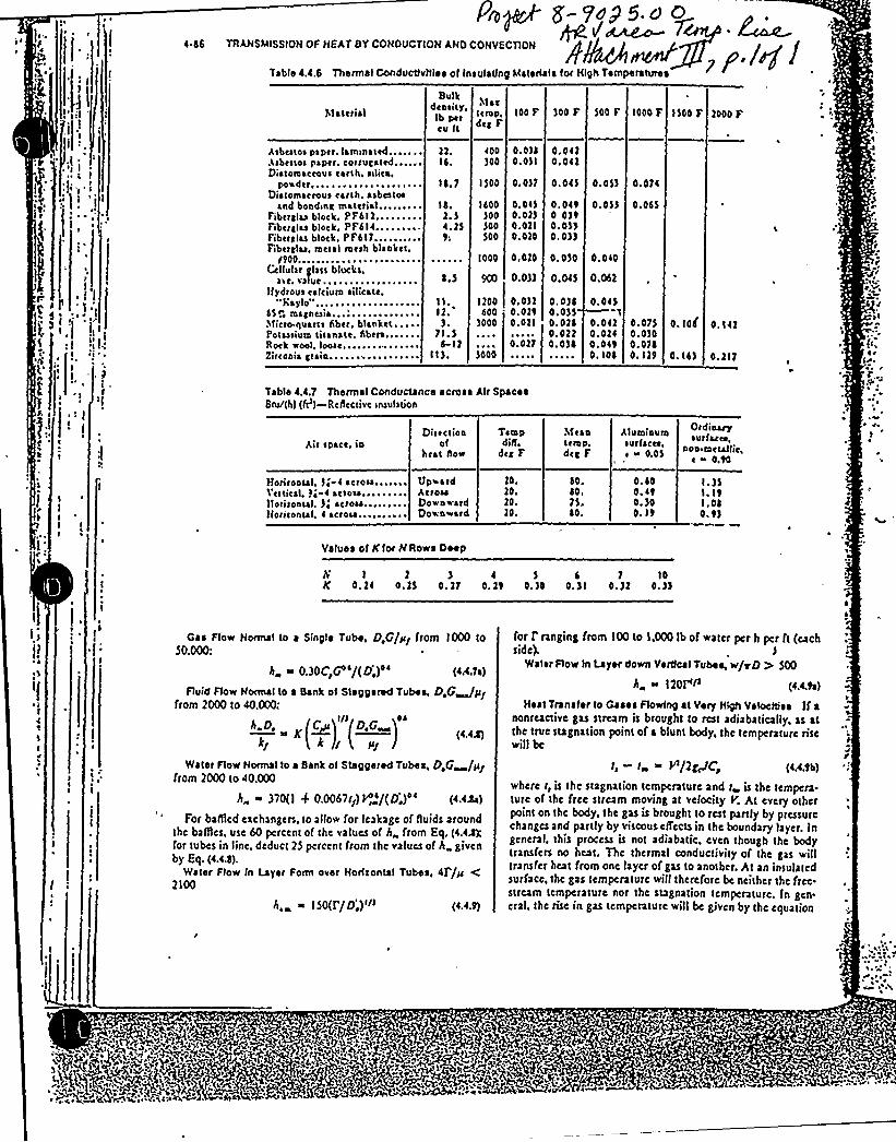
h = 1.6 Btu/hr sq ft 'F (table 4.4.11 of Mark's handbook. Attachment 2 to thiscalculation)
k = 0.045 Btu/hr ft 'F (Table 4.4.6 of Mark's handbook: Attachment 3 to thiscalculation)
For purposes of this evaluation, k is assumed to be constant over the range of temperatures inquestion. "h" has been selected from Attachment 2 on the basis of large horizontal pipes. Thisvalue is felt to produce reasonable results for this calculation.
The resultant surface temperatures calculated for the heat sources identified in the ARV area and thearea above are provided in Tables 1 and 2, respectively, shown on the followingpages.

h t
Devonrue Calculation Project No. 8-9025.00Date: April9, 1991
Page 7 of 24
Subject: Ginna Atmospheric Relief Valve (ARV) Area Ambient Temperature Rise-Revised Methodology
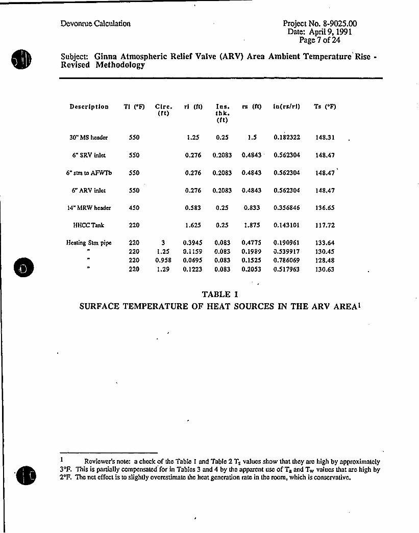
Description Tl ('F) Circ. rl (ft) Ins. rs (ft) ln(ra/rl) Ts ('F)(rt) thk.
(ft)
30" MS header 550
6" SRV inlet 550
6" ARV inlet 550
14" MRW header 450
HHCC Tank 220
6" stm to AFWTh 550
1.25 0.25 1.5 0.182322 148.31
0.276 0.2083 0.4843 0.562304 148.47
0.276 0.2083 0.4843 0.562304 148.47
0.276 0.2083 0.4843 0.562304 148.47
0.583 0.25 0.833 0.356846 136.65
1.625 0.25 1.875 0.143101 117.72
Heating Stm pipe 220 3 0.3945 0.083 0.4775 0.190961 133.64220 1.25 0.1159 0.083 '0.1989 0.539917 130.45220 0.958 0.0695 0.083 0.1525 0.786069 128.48
220 1.29 0.1223 0.083 0.2053 0.517963 130.63
TABLE 1
SURFACE TEMPERATURE OF HEAT SOURCES IN THE ARV AREA>
Rcviewcr's note: a check of the Table 1 and Table 2 T, values show that they arc high by approximately3'F. This is partially compcnsatcd for in Tables 3 and 4 by the apparent use of Ta and Tw values that are high by2'F. The net effect is to slightly ovcrcstimate the heat generation rate in the room, which is conservative.
Devonrue Calculation Project No. 8-9025.00Date: April9, 1991
Page 8 of 24
Subject: Ginna Atmospheric Relief Valve (ARV) Area Ambient Temperature Rise-Revised Methodology
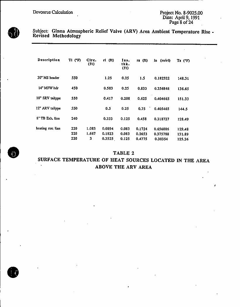
Description Tl ('F) Circ. rl (ft) Ins. rs (ft) ln (rs/rl) Ts ('F)(ft) thk.
(ft)
30" MS header 550
14" MFWhdr 450
8" TB Exh. line 240
10" SRV tailppe 550
12" ARV tailppe 550
1.25 0.25 1.5 0.182322 148.'31
0.583 0.25 0.833 0.356846 136.65
0.417 0.208 0.625 0.404665 151.33
0.5 0.25 0.75 0.405465 144.5
0.333 0.125 0.458 0.318727 128.49
heating stm line 220 1.083 0.0894 0.083 0.1724 0.656886 129.48220 1.667 0.1823 0.083 0.2653 0.375788 131.89220 3 0.3525 0.125 0.4775 0.30354 125.36
TABLE 2
SURFACE TEMPERATURE OF HEAT SOURCES LOCATED IN THE AREAABOVE THE ARV AREA
Devonrue Calculation Project No. 8-9025.00Date: April9, 1991
Page9of 24
Subject: Ginna Atmospheric Relief Valve (ARV) Area Ambient Temperature Rise-Revised Methodology
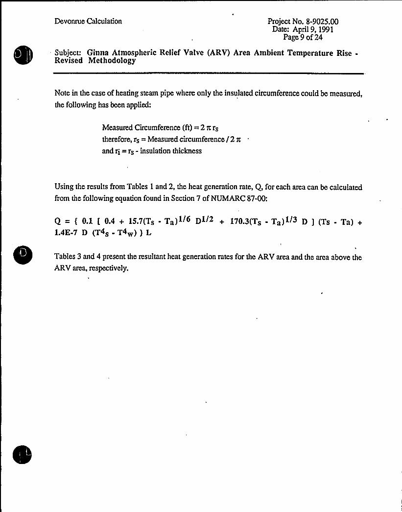
Note in the case of heating steam pipe where only the insulated circumference could be measured,
the following has been applied:
Measured Circumference (ft) = 2 x rs
therefore, rs = Measured circumference /2 zand ri = rs - insulation thickness
Using the results from Tables 1 and 2, the heat generation rate, Q, for each area can be calculated
from the followingequation found in Section 7 of NUMARC87-00:
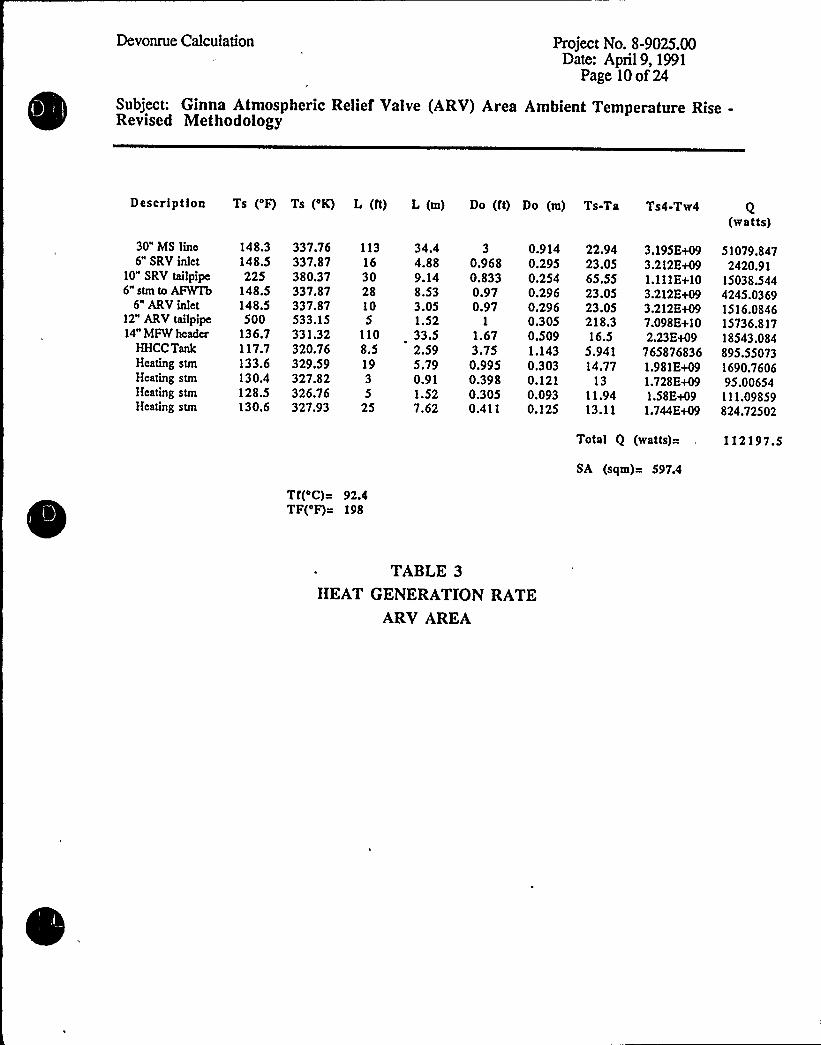
Q ( 01 [ 04 + 157(Ts . Ta)l/6 Dl/2 + 1703(Ts Ta)l/3 D ] (Ts - Ta) +1.4E-7 D (T4s - T4w) ) L
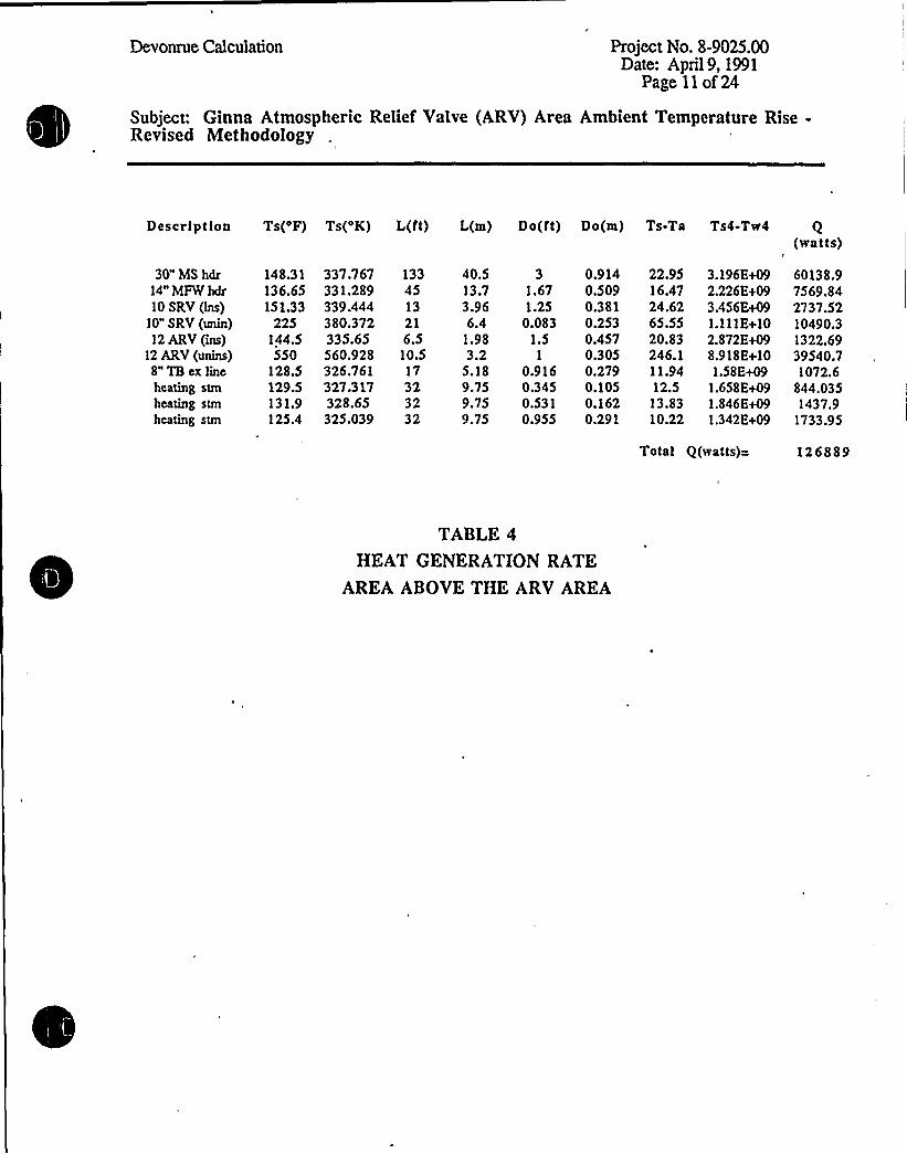
Tables 3 and 4 present the resultant heat generation rates for the ARVarea and the area above the
ARV area, respectively.

Devonrue Calculation Project No. 8-9025.00Date: April9, 1991
Page 10 of24
Subject: Ginna Atmospheric Relief Valve (ARV) Area Ambient Temperature Rise-Revised Methodology
Description Ts ('F) Ts ('K) L (ft) L (m) Do (ft) Do (m) Ts-Ta Ts4-Tw4 Q(watts)
30" MS linc6" SRV inlet
10" SRV tailpipe6" stm to AFWrb
6" ARV inlet12" ARV tailpipe14" MFW hcada
HHCC TankHeating stmHeating stmlieating stmHeating stm
148.3 337.76 113 34.4148.5 337.87 16 4.88225 380.37 30 9.14
148.5 337.87 28 8.53148.5 337.87 10 3.05500 533.15 5 1.52
136.7 331.32 110 33.5117.7 320.76 8.5 2.59133.6 329.59 19 5.79130.4 327.82 3 0.91128.5 326.76 5 1.52130.6 327.93 25 7.62
3 0.9140.968 0.2950.833 0.2540.97 0.2960.97 0.296
1 0.3051.67 0.5093.75 1.1430.995 0.3030.398 0.1210.305 0.0930.411 0.125
22.9423.0565.5523.0523.05218.316.5
5.94114.77
1311.9413.11
3.195E+093.212 E+091.111E+103.212E+093.212 E+097.098 E+102.23Et09
7658768361.981E+091.728E+091.5&E+091.744 E+09
51079.8472420.91
15038.5444245.03691516.084615736.81718543.084895.550731690.760695.00654111.09859824.72502
Tr(oc) = 92.4TF(oF)= 198
Total Q (watts)=
SA (sqm)= 597.4
112197.5
TABLE 3
HEAT GENERATION RATEARV AREA
Devonrue Calculation Project No. 8-9025.00Date: April9, 1991
Page 11 of 24
Subject: Ginna Atmospheric Relief Valve (ARV) Area Ambient Temperature Rise-Revised Methodology
Description Ts('F) Ts('K) L(lt) L(m) Do(ft) Do(m) Ts-Ta Ts4-Tw4(watts)
30" MS hdr14" MFW hdr10 SRV (Ins)
10" SRV (unin)12 ARV (ins)
12 ARV (unins)8" TB cx lincheating stmheating stmheating stm
148.31136.65151.33
225144.5550
128.5129.5131.9125.4
337.767331.289339.444380.372335.65560.928326.761327.317328.65325.039
133 40.5 3 0.914 22.9545 13.7 1.67 0.509 16.4713 3.96 1.25 0.381 24.6221 6.4 0.083 0.253 65.556.5 1.98 1.5 0.457 20.8310.5 3.2 1 0.305 246.117 5.18 0.916 0.279 11.9432 9.75 0.345 0.105 12.532 9.75 0.531 0.162 13.8332 9.75 0.955 0.291 10.22
3.196E+092.226 E+093.456E+091.111E+102.872E+098.918 E+101.58E+09
1.658E+091.846E+091.342E+09
60138.97569.842737.5210490.31322.6939540.71072.6
844.0351437.9
1733.95
Total Q(watts)= 126889
TABLE 4
HEAT GENERATION RATEAREA ABOVE THE ARV AREA
Devonrue Calculation Project No. 8-9025.00Date: April9, 1991
Page 12 of 24
Subject: Ginna Atmospheric Relief Valve (ARV) Area Ambient Temperature Rise-Revised Methodology
Tables 3 and 4 show that the SRV tail pipes were considered to have a surface temperature of 225
'F. This value is based upon the followingjustification:
As previously stated in the Assumptions section, it is reasonable to assume that only 1 of 4
safety valves in each Main Steam header willbe automatically cycled upon MSIVclosure
following reactor trip in response to the LOOP. In order to apply the NUMARC 87-00
correlations, the two affected tail pipes will be treated as 15 ft. each (30 ft. total) ofuninsulated 10" diameter piping.
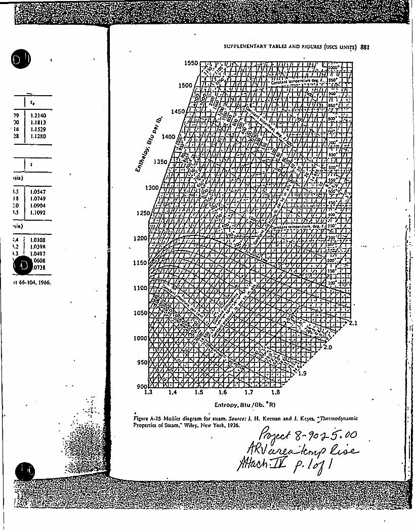
The set pressure of the first safety valve is 1085 psig per Ginna UFSAR section 10.3.2.4.
The steam saturation temperature at this pressure is 556 'F. The safety valve is treated as a
throttling device which acts as a fiow restrictor, leading to a pressure drop in the fluid. It is
reasonable to assume that there is no change in enthalpy across the safety valve since the
valve inlet and the tail pipe exit to atmospheric pressure are well separated and the exit is
relatively far downsueam from the valve itself. Therefore, considering the release of steam
through the safety valve to be isenthalpic and reducing in pressure to essentially
atmospheric conditions, the resultant temperature on the constant enthalpy curve of the
Mollier diagram (Attachment 4 to this calculation) is approximately 300'F. The SRV
tailpipes ate expected to remain at this temperature for only a short period of time (less than
1 hour), since the ARVs willbe used for cooldown and depressurization shortly after the
onset of the event, precluding further SRV actuation.
In order to use a steady state temperature calculation based on the NUMARC 87-00
methodology, a constant 4 hour heat source term must be used. The SRV tailpipe heat
source contribution is approximated by selecting a constant 4 hour tailpipe temperature that
willprovide a heat source contribution that conservatively approximates the contribution
from the actual brief period at high temperature. Since heat generation, Q, is directly
proportional to the product of the temperature difference (between the hot surface and the
ambient air) and time (dT*t), the following is reasonable:
Since Q —(300'F - 104 'F) * 1 hour ( Q' (200 'F - 104'F) * 4 hours, a surface
temperature of225 'F is chosen for the tailpipes and willproduce conservative results.

0
0
Devonrue Calculation Project No. 8-9025.00Date; April9, 1991
Page 13 of 24
Subject: Ginna Atmospheric Relief Valve (ARV) Area Ambient Temperature Rise-Revised Methodology
As indicated in Table 3, the surface temperature of the uninsulated 12" ARV tail pipe is assumed to
be 500'F when calculating the heat generation rate in the ARV area. 'Ihis is felt to be conservative
since steam header temperature at the time when ARVoperation begins willbe somewhat less than
the 550'F Main steam system design temperature. The ARVs willnot be in operation until the
operators take manual control of them. Therefore, the tail pipe is not expected to see steam
conditions for the fullfour hours. In addition, the ARVs willbe used to remove decay heat as wellas cooldown the plant. Since the coping scenario involves plant cooldown, steam header
temperatures willdecrease below the hot standby operating temperattue over the course of the fourhours and the temperature of the steam seen by the ARV tailpipe willalso decrease. On this basis,
the use of a 500'F tailpipe operating temperature is judged to result in a conservative heat
generation rate.
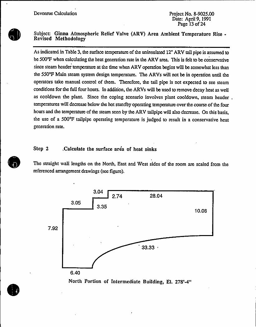
Step 2 „.Calculate the surface area of heat sinks
The straight wall lengths on the North, East and West sides of the room are scaled from thereferenced arrangement drawings (see figure).
3.05
3.04
3.35
2.74 28.04
10.06
7.92
33.33 "
6.40
North Portion of Intermediate Building, El. 278'-4"
Devonrue Calculation Project No. 8-9025.00Date: April9 1991
Page 14 of24
Subject: Ginna Atmospheric Relief Valve (ARV) Area Ambient Temperature Rise-Revised Methodology
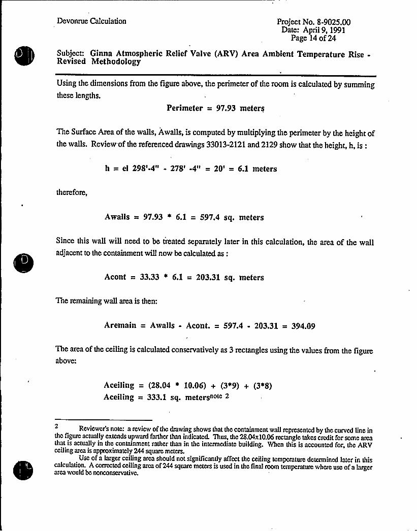
Using the dimensions from the figure above, the perimeter of the room is calculated by summingthese lengths.
Perimeter = 97.93 meters
The Surface Area of the walls, Awalls, is computed by multiplying the perimeter by the height ofthe walls, Review of the referenced drawings 33013-2121 and 2129 show that the height, h, is:
h = el 298'-4" - 278'4" = 20' 6.1 meters
therefon:,
Awalls = 97.93 ~ 6.1 = 5974 sq. meters
Since this wall will need to be treated separately later in this calculation, the area of the walladjacent to the containment wiH now be calculated as:
Acont = 33.33 ~ 6.1 = 203.31 sq. meters
The remaining wall area is then:
Aremain = Awalls - Acont. = 597.4 - 203.31 = 394.09
The area of the ceiling is calculated conservatively as 3 rectangles using the values Qom the figureabove:
Aceiling = (28.04 * 10.06) + (3*9) + (3*8)Aceiling = 333.1 sq. metersno'c 2
Reviewer's note: a review of the drawing shows that the containment wall represented by the curved line inthe figure actually extends upward farther than indicated. Thus, thc 28.04x10.06 rectangle takes credit for some areathat is actually in the containmcnt rather than in the intermediate building. When this is accounted for, thc ARVceiling area is approximately 244 square meters.
Usc of a hrger ceiling area should not significantly affect thc ceiling temperature determined later in thiscalculation. A corrected ceiling area of244 square meters is used in thc final room temperature where usc ofa largerarea would bc nonconservativc.
,
0
Devonrue Calculation Prospect No. 8-9025.00Date: April9, 1991
Page 15 of24
Subject: Ginna Atmospheric Relief Valve (ARV) Area Ambient Temperature Rise-Revised Methodology
The total surface area acting as a heat sink is therefore,
Atotal = Aceiling + Awalls = 333.1 + 597.4 = 930.4 m2
Using this information, the followingproportions are determined:
Proportion of the ceiling to total = 333.1 / 930.4 = 0.36
Proportion of the containment wall to total = 203.31 / 930.4 = 0.22
Proportion of the remaining walls to total = 394.09 / 930.4 = 0.42
Step 3 Determine the amount of heat transferred into the ceiling fromthe rooms above and below
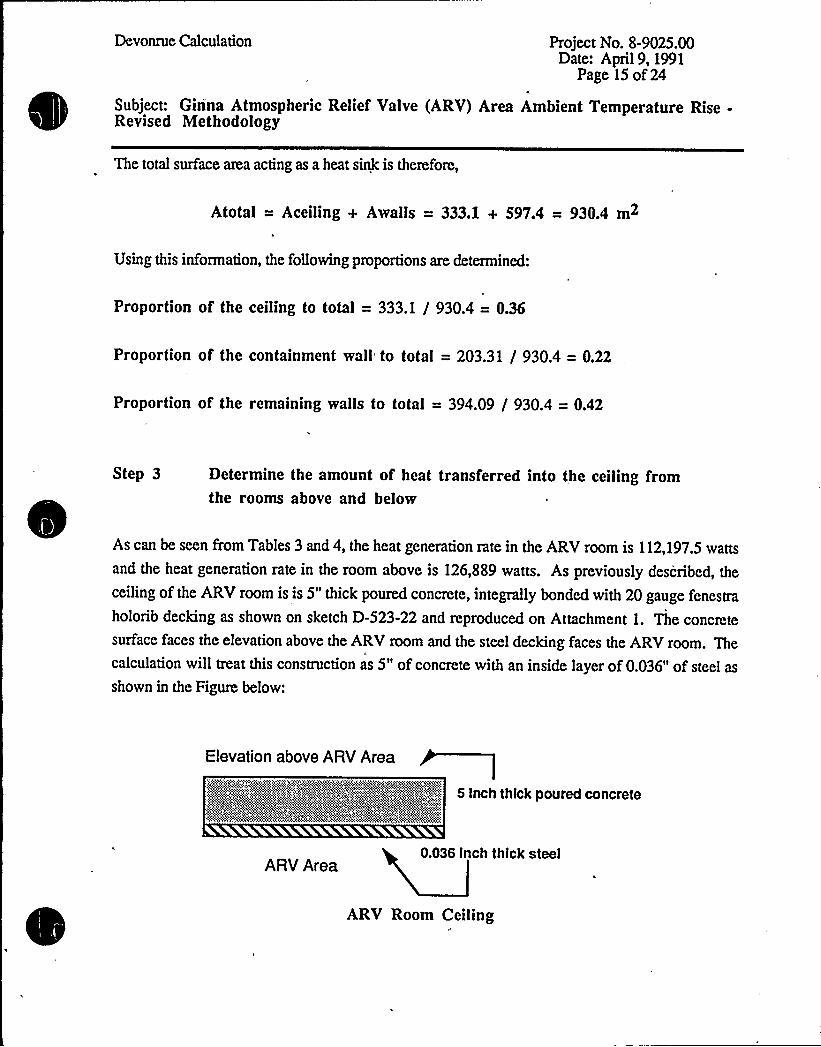
As can be seen from Tables 3 and 4, the heat generation rate in the ARV room is 112,197.5 wattsand the heat generation rate in the room above is 126,889 watts. As previously described, the
ceiling of the ARV room is is 5" thick poured concrete, integrally bonded with 20 gauge fenestra
holorib decking as shown on sketch D-523-22 and reproduced on Attachment 1 ~ The concretesurface faces the elevation above the ARV room and the steel decking faces the ARVroom. Thecalculation willtreat this construction as 5" of concrete with an inside layer of 0.036" of steel as
shown in the Figure below:
Elevation above ARV Area
5 Inch thick poured concrete
ARVArea0.036 Inch thick steel
ARV Room Ceiling
0

Devonrue Calculation Project No. 8-9025.00Date: April9, 1991
Page 16 of 24
Subject: Ginna Atmospheric Relief Valve (ARV) Area Ambient Temperature Rise-R'evised Methodology
The heat transfer rate into the concrete surface from the area above willbe calculated using fiat plate
convective heat transfer correlations for the upper surface of a cooled plate (i.e., the plate is coolerthan the air). The followingrelationships willbe applied from section 9.6 of In+opera and Dewittusing the dimensionless parameters of the Nusselt number, Nu, and the Rayleigh number, Ra:
Ra = fgB ( Ts - T~) L3 ] / v a
Nu '= 0.27Ra</4
Nu = hc L/k; or hc-k Nu/L
Q=hcAdT
where:
Ts = the surface temperature of the plate
T~ = the temperature of the air in the room
B = lfl'fwhere Tf=(T~+Ts)/2L = Surface area of the plate/ Perimeter
g = the acceleration due to gravity, 9.8 m/sec2
As can be seen from the above equations, the air temperature in this room must be calculated toobtain T~.
T~ willbe calculated using the NUMARC 87-00 equation, T~ = Ti + [Q/A]3/4 whereT = the resultant ambient air temperatutc in the room above the ARV area;
Ti = the initial temperature of the walls considered as heat sinks
Q = heat generation rate;
A = the total surface area ofwalls and ceilings acting as heat sinks.
From arrangement drawing 33013-2129, it can be seen that the perimeter of the room is virtuallyidentical to that of the ARV room, i.e., 97.93 meters. and that the height of these walls is 17 feet,or 5.2 meters. The area of the ceiling in this room willbe neglected to ensure conservative results.
Devonrue Calculation Project No. 8-9025.00Date: April9, 1991
Page 17of24
Subject: Ginna Atmospheric Relief Valve (ARV) Area Ambient Temperature Rise-Revised Methodology
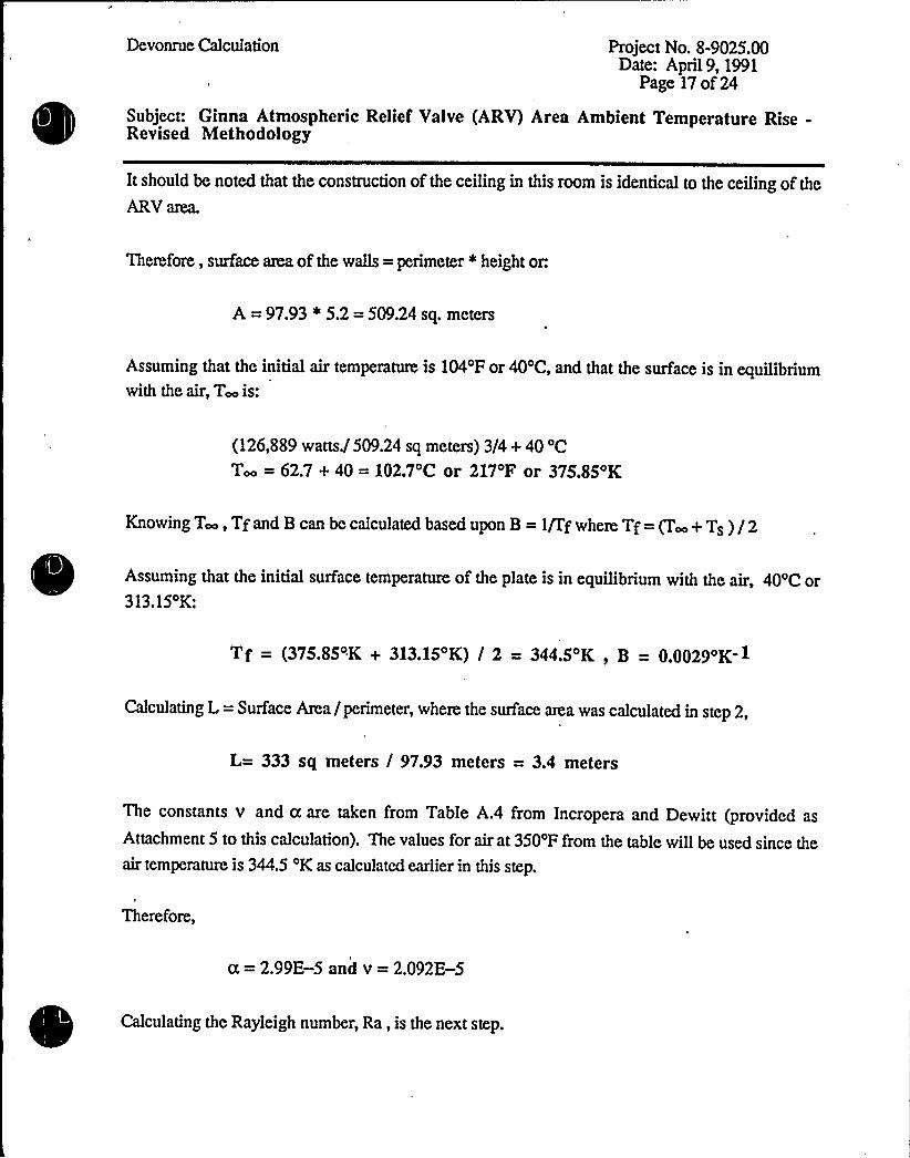
It should be noted that the construction of the ceiling in this room is identical to the ceiling of the
ARV area.
'Iherefore, surface area of the walls = perimeter *height or.
A = 97.93 * 5.2 = 509.24 sq. meters
Assuming that the initial air temperature is 104'F or 40'C, and that the surface is in equilibriumwith the air, T~ is:
(126,889 watts./509.24 sq meters) 3/4+ 40 'CT = 62.7 + 40 = 1Q2.7'C or 217'F or 375.85'K
Knowing T, Tfand B can be calculated based upon B = 1fffwhere Tf= g ~+ Ts ) /2
Assuming that the initial surface temperature of the plate is in equilibrium with the air, 40'C or313 15 K:
Tf (375 85 .K + 313 15 K) / 2 —344 5 K B — Q QQ29OK- 1
Calculating L = Surface Area /perimeter, where the surface area was calculated in step 2,
L= 333 sq meters / 97.93 meters = 3.4 meters
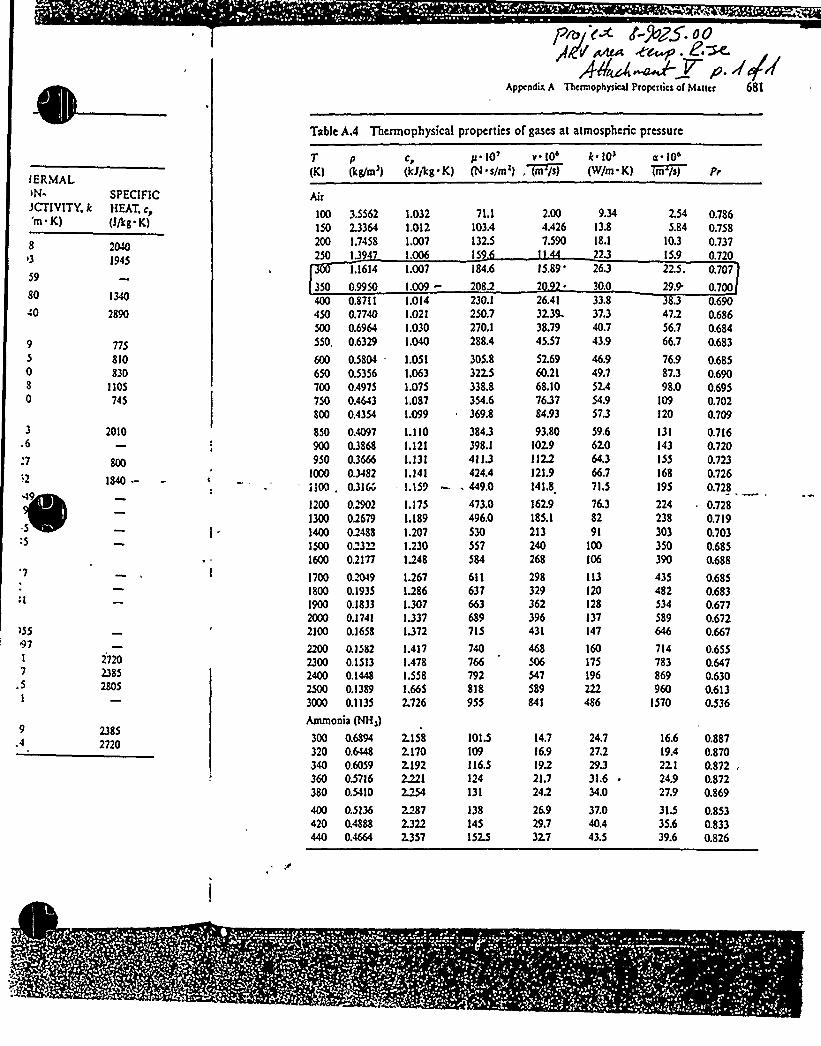
The constants v and a are taken from Table A.4 from Incropera and Dewitt (provided as
Attachment 5 to this calculation). The values for air at 350'F from the table willbe used since theair temperature is 344.5 'K as calculated earlier in this step.
Therefore,
a = 2,99E-5 and v = 2.092E-5
Calculating the Rayleigh number, Ra, is the next step.
Devonrue Calculation Project No. 8-9025.00Date: April9, 1991
Page 18 of 24
Subject: Ginna Atmospheric Relief Ualve (ARV) Area Ambient Temperature Rise-Revised Methodology
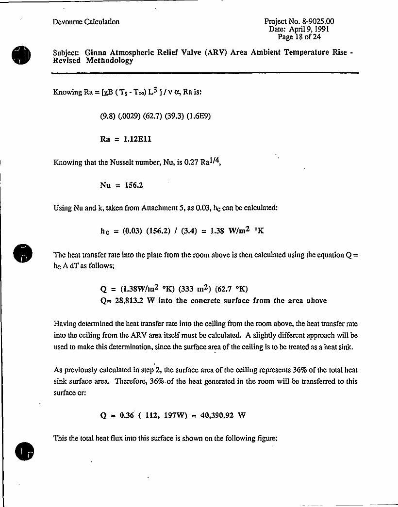
Knowing Ra= [gB (Ts- T~) L3]/v tx, Rais:
(9.8) (.0029) (62.7) (39.3) (1.6E9)
Ra = 1.12E11
Knowing that the Nusselt number, Nu, is 0.27 Ral/4,
Nu = 156.2
Using Nu and k, taken from Attachment 5, as 0.03, hc can be calculated:
hc = (003) (1562) / (3.4) = 1.38 W/m2 'K
The heat transfer rate into the plate from the room above is then calculated using the equation Q =
hc A dT as follows;
Q — (138W/m2 oK) (333 m2) (62,7 oK)
Q= 28,813.2 W into the concrete surface from the area above
Having determined the heat transfer rate into the ceiling from the room above, the heat transfer rate
into the ceiling from the ARU area itself must be calculated. A slightly different approach willbe
used to make this determination, since the surface area of the ceiling is to be treated as a heat sink.
As previously calculated in step 2, the surface area of the ceiling represents 36% of the total heat
sink surface area. Therefore, 36% of the heat generated in the room willbe transferred to this
surface or:
Q = 0.36 ( 112, 197W) = 40,390.92 W
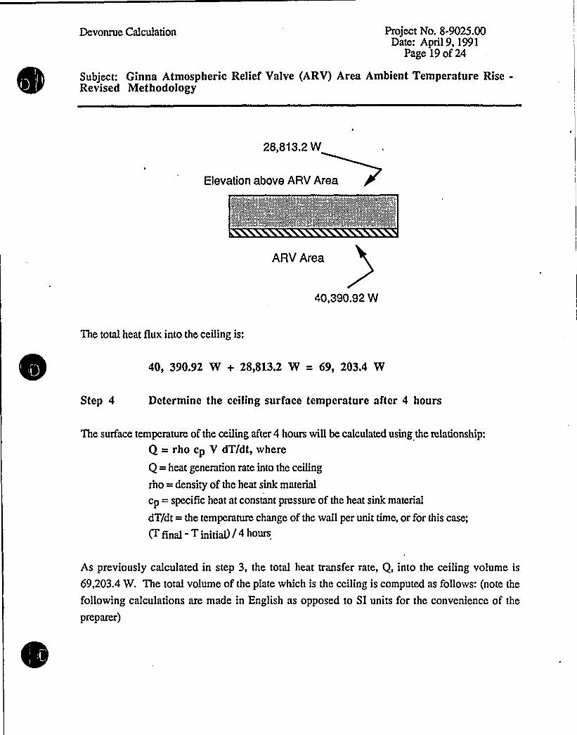
This the total heat flux into this surface is shown on the following figure:

Devonrue Calculation Project No. 8-9025.00Date: April9, 1991
Page 19 of 24
Subject: Ginna Atmospheric Relief Valve (ARV) Area Ambient Temperature Rise-Revised Methodology
28,813.2 W
Elevation above ARV Area
ARV Area
40,390.92 W
The total heat flux into the ceiling is:
40, 390.92 W + 2S,S13.2 W = 69, 203.4 W
Step 4 Determine the ceiling surface temperature after 4 hours
The surface temperature of the ceiling after 4 hours willbe calculated using the relationship:
Q = rho cp V dT/dt, where
Q = heat generation rate into the ceiling
rho = density of the heat sink material
cp = specific heat at constant pressure of the heat sink material
dT/dt = the temperatute change of the wall per unit time, or for this case;
(T final - T initial)/4 hours.
As previously calculated in step 3, the total heat transfer rate, Q, into the ceiling volume is
69,203.4 W. The total volume of the plate which is the ceiling is computed as follows: (note the
following calculations are made in English as opposed to SI units for the convenience of the
preparer)
Devonrue Calculation Prospect No. 8-9025.00Date: April9, 1991
Page 20 of 24
Subject: Ginna Atmospheric Relief Valve (ARV) Area Ambient Temperature Rise-Revised Methodology
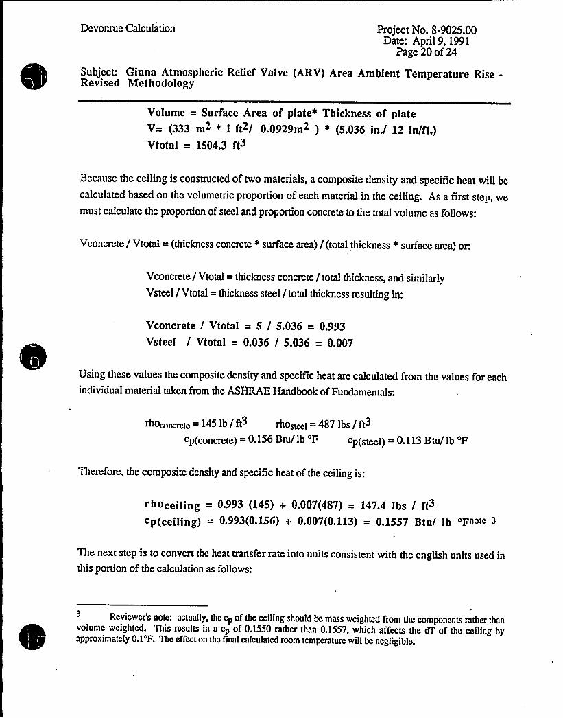
Volume = Surface Area of plate» Thickness of plateV= (333 m2 * 1 ft / 0.0929m2 )» (5.036 in'2 in/ft.)Vtotal = 1504.3 ft3
Because the ceiling is constructed of two materials, a composite density and specific heat willbe
calculated based on the volumetric proportion of each material in the ceiling. As a first step, wemust calculate the proportion of steel and proportion concrete to the total volume as follows:
Vconcrete/ Vtotal = (thickness concrete * surface area) /(total thickness * surface area) or.
Vconctete/ Vtotal = thickness concrete / total thickness, and similarlyVsteel / Vtotal = thickness steel / total thickness resulting in:
Vconcrete / Vtotal = 5 / 5.036 = 0.993
Vsteel / Vtotal = 0.036 / 5.036 = 0.007
Using these values the composite density and specific heat are calculated from the values for eachindividual material taken from the ASHRAE Handbook ofFundamentals:
rhoconcrctc ——145 lb / ft3 rhostcei = 487 lbs / ft3
cp(concrete) = 0.156 Btu/ lb 'F cp(steel) = 0.113 Btu/ lb 'F
Therefore, the composite density and specific heat of the ceiling is:
rhoceiling = o993 (145) + 0.007(487) = 147.4 Ibs / ft3
cp(ceiling) = 0.993(0.156) + 0.007(0.113) = 0.1557 Btu/ lb 'Fn«e 3
The next step is to convert the heat transfer rate into units consistent with the english units used inthis portion of the calculation as follows:
Reviewer's note: actually, the cp of the ceiling should bc mass weighted from the components rather than~
~
volume weighted. This results in a cp of 0.1550 rather than 0.1557, which affects the dT of the ceiling byapproximately 0.1'F. The effect on thc final calculated room temperature willbc negligible.

mr
Devonrue Calculation Project No. 8-9025.00Date: April9, 1991
Page 21 of 24
Subject: Ginna Atmospheric Relief Valve (ARV) Area Ambient Temperature Rise-Revised Methodology
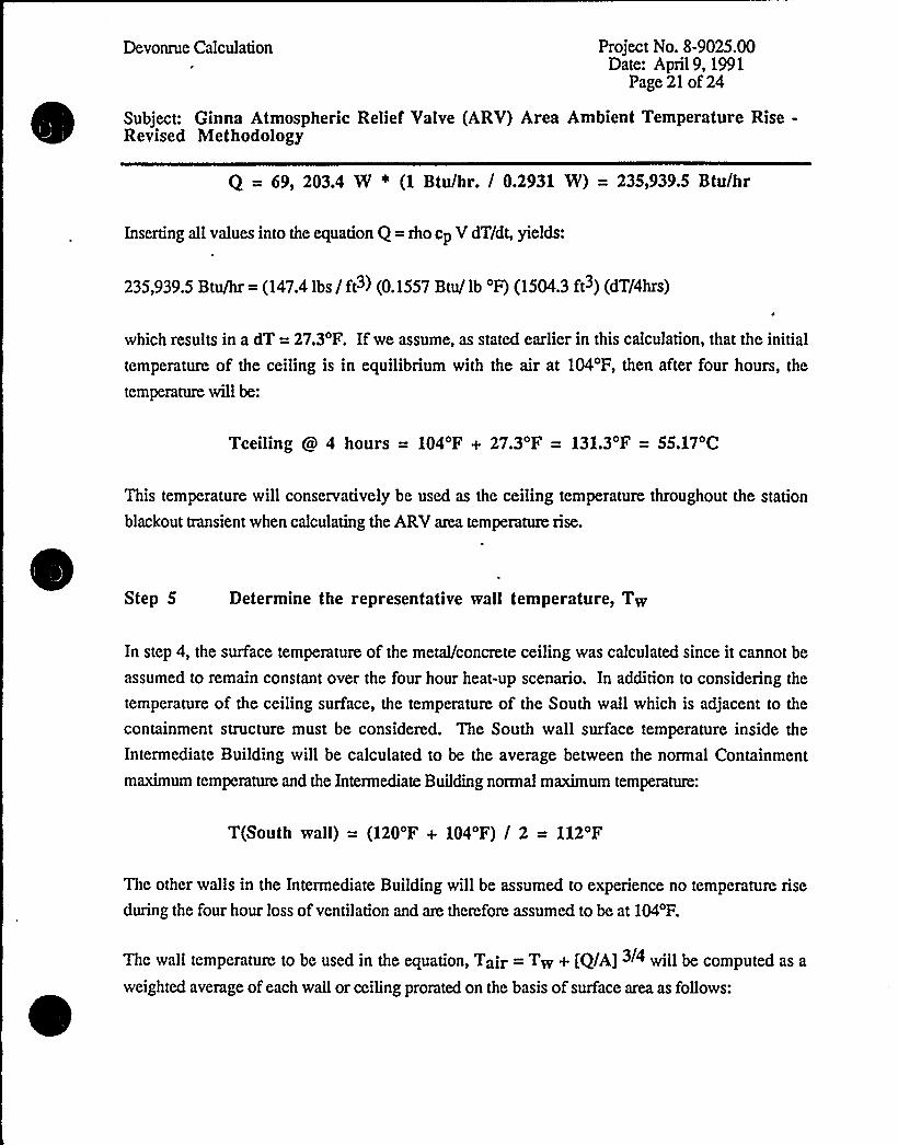
Q = 69, 203.4 W ~ (1 Btu/hr. / 0.2931 W) = 235,939.5 Btu/hr
Inserting all values into the equation Q = rho cp V dT/dt, yields:
235,939.5 Btu/hr = (147.4 lbs / ft3) (0.1557 Btu/ lb 'F) (1504.3 ft~) (dT/4hrs)
which results in a dT = 27.3'F. Ifwe assume, as stated earlier in this calculation, that the initial
temperature of the ceiling is in equilibrium with the air at 104'F, then after four hours, the
temperature willbe:
Tceiling 4 hours = 104'F + 27.3'F = 131.3'F = 55.17'C
This temperature willconservatively be used as the ceiling temperature throughout the station
blackout transient when calculating the ARV area temperature rise.
Step 5 Determine the representative wall temperature, Tw
In step 4, the surface temperature of the metal/concrete ceiling was calculated since it cannot be
assumed to remain constant over the four hour heat-up scenario. In addition to considering the
temperature of the ceiling surface, the temperature of the South wall which is adjacent to the
containment structure must be considered. The South wall surface temperature inside the
Intermediate Building will be calculated to be the average between the normal Containment
maximum temperature and the Intermediate Building normal maximum temperature:
T(South wall) = (120'F + 104'F) / 2 = 112'F
The other walls in the Intermediate Building willbe assumed to experience no temperature rise
during the four hour loss ofventilation and are therefore assumed to be at 104'F.
The wall temperature to be used in the equation, Tair —Tw + [Q/A]3/4 willbe computed as a
weighted average of each wall or ceiling prorated on the basis of surface area as follows:
Devonrue Calculation Project No. 8-9025.00Date: April9, 1991
Page 22 of 24
Subject: Ginna Atmospheric Relief Valve (ARV) Area Ambient Temperature Rise-Revised Methodology
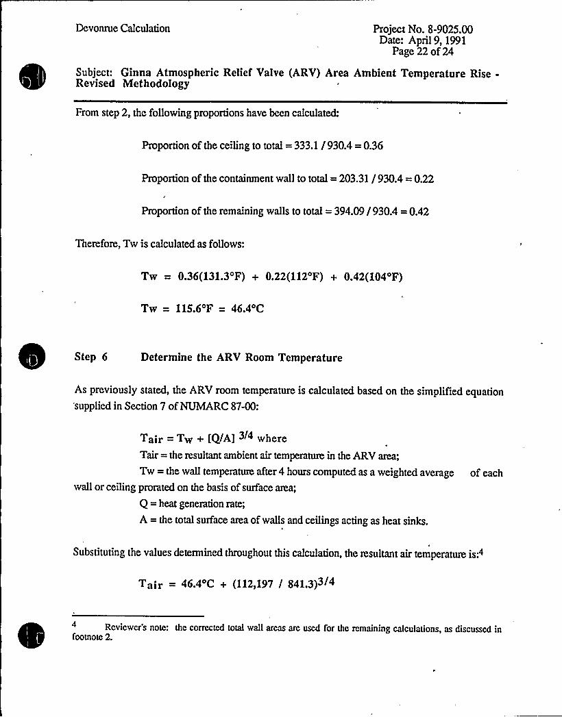
From step 2, the followingproportions have been calculated:
Proportion of the ceiling to total = 333.1 /930.4 = 0.36
Proportion of the containment wall to total = 203.31 /930.4 = 0.22
Proportion of the remaining walls to total = 394.09/930.4 = 0.42
Therefore, Tw is calculated as follows:
Tw = 0.36(131.3'F) + 0.22(112'F) + 0.42(104'F)
Tw = 115.6'F = 46.4'C
Step 6 Determine the ARV Room Temperature
As previously stated, the ARV room temperature is calculated based on the simplified equation'supplied in Section 7 ofNUMARC87-00:
Tair —Tw + [Q/A] 3/4 where
Tair = the resultant ambient air temperature in the ARVarea;
Tw = the wall temperature after 4 hours computed as a weighted average
wall or ceiling prorated on the basis of surface area;
Q = heat generation rate;
A = the total surface area ofwalls and ceilings acting as heat sinks.
of each
Substituting the values determined throughout this calculation, the resultant air temperattue is:4
Tajr = 46.4 C + (112ql97 / 841.3)3/4
Reviewer's note: thc corrected total wall areas arc used for thc remaining calculations, as discussed infootnote 2.

a ' I
Devonrue Calculation Project No. 8-9025.00Date: April9, 1991
Page 23 of 24
Subject: Ginna Atmospheric Relief Valve (ARV) Area Ambient Temperature Rise-Revised Methodology
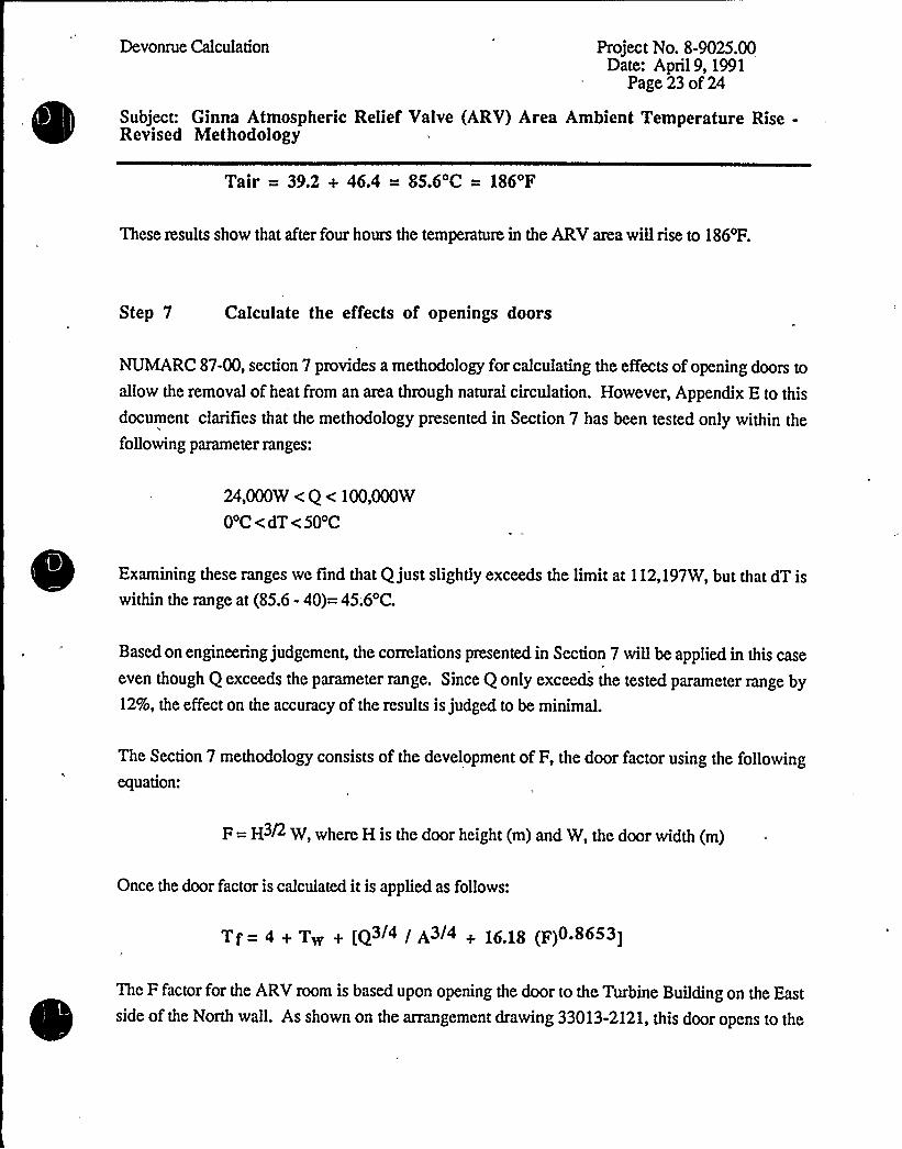
Tair = 39.2 + 46.4 = 85.6'C = 186'F
These results show that after four hours the temperanue in the ARVaa:a willrise to 186'F.
Step 7 Calculate the effects of openings doors
NUMARC87-00, section 7 provides a methodology for calculating the effects ofopening doors to
allow the removal of heat from an area through natural circulation. However, Appendix E to this
document clarifies that the methodology presented in Section 7 has been tested only within the
following parameter ranges:
24,000W < Q < 100,000W
0 C<dT<50'C
Examining these ranges we find that Q just slightly exceeds the limitat 112,197W, but that dT is
within the range at (85.6 - 40)= 45.6'C.
Based on engineering judgement, the correlations presented in Section 7 willbe applied in this case
even though Q exceeds the parameter range. Since Q only exceeds the tested parameter range by12%, the effect on the accuracy of the results is judged to be minimal.
The Section 7 methodology consists of the development of F, the door factor using the followingequation:
F = H3/2 W, where H is the door height (m) and W, the door width (m)
Once the door factor is calculated it is applied as follows:
Tf= 4 + Tw + [(} / A3/ + 16.18 (F)0.8653]
The F factor for the ARVroom is based upon opening the door to the Turbine Building on the East
side of the North wall. As shown on the arrangement drawing 33013-2121, this door opens to the

Devonrue Calculation Project No. 8-9025.00Date: April9, 1991
Page 24 of 24
Subject: Ginna Atmospheric Relief Valve (ARV) Area Ambient Temperature Rise-Revised Methodology
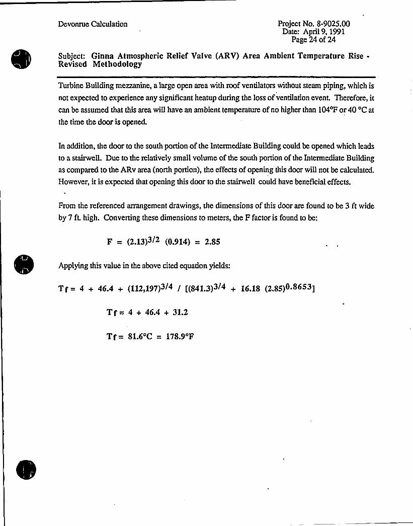
Turbine Building mezzanine, a large open area with roof ventilators without steam piping, which is
not expected to experience any significant heatup during the loss ofventilation event. Therefore, itcan be assumed that this area willhave an ambient temperature ofno higher than 104'F or 40 'C at
the time the door is opened.
In addition, the door to the south portion of the Intermediate Building could be opened which leads
to a stairwell. Due to the relatively small volume of the south portion of the Intermediate Building
as compared to the ARv area (north portion), the effects ofopening this door willnot be calculated.
However, it is expected that opening this door to the stairwell could have beneficial effects.
From the referenced arrangement drawings, the dimensions of this door are found to be 3 ft wide
by 7 ft. high. Converting these dimensions to meters, the F factor is found to be:
F = (2.13)3/2 (0.914) = 2.85
Applying this value in the above cited equation yields:
Tf = 4 + 46.4 + (112,197)3/4 / [(841.3)3/ + 16.18 (2.85)0 8653]
T f = 4 + 46.4 + 31.2
Tf= 81.6oC = 178.9'F
C
gf(Y~gdfrcl~> T
g.)8-<
46,
TIP ~"~>~ ~JoLoa.iS
QEc.P
~,~ h~
( p,~'

,k
~t ~-'
Bcrcnson finds better agrccm»nt with Ih» data if Ka 0.09.For very small wires, th» heal flux will exceed that predictedby this flat plate formula. A reliable prcdiction of Ihc crili»altemperature is not availablc.
For nucleate boiling accompanied by for»cd convection, Ibcheat flux may bc approximated by Ihe sum of thc heal flux forpool boiling alone and ihe heat flux for forced convection alone.This proecdurc will nol be satisfactory al high qualities, andno satisfaclory corrcbtion exists for the maximum heal flux.
For a given liquid and boiling prcssure, thc nature of thcsurface may substantially influcnce the flux al a given (AI)~
Tabl» 4.4.l0. These data may bc used as rough approximationsfor a bank of submerged tubes. Film coeliicients for scaledeposits arc given in Table 4.4.g.
For forced~!ion eva poraion, vapor binding is also encoun-ter»d. Thus with liquid benzene entering a 4 pass steam jack.cled pipe at 0.9 fps, up to thc point where 60 percent by «eightwas vaporized, the maximum flux of 60,000 Btu/h/fl'as
For comparison, in a natural convection evaporator, a »aumum flux of 73.000 Btu/h/ft «as obtained at (4I)~ of I(O Ii
Combined Convection and Radiation Coe!II»ion!acas»s of heal I~. such as that from bare and insulated p t6,«here loss is by convection Io the air and radiation to the vabof th» enclosing, space it is convenient to usc a combined coo'..veclion and radiation cocilicient (h, + h,). The rate of b»atloss thus bccom»s ~0
q m (h, + h,)A(SI)r (4.42$ )
where (AI), is lhc Icmpcralure ditfcrcncc. deg F, bctureea tbasurfa»c of the hot body and thc walls of the space. In cvaluat'. '„;ing, (h, + h,), h, should bc calculatcdby thc appropriate coo $vection formula fsec Eqs. (4.4.llc) Io(4.4.IIS)f and h, froln tb» yequation
h, m 0.00685!(T„/)00)l
Tabl ~ 4.4.10 Maximum Rux and Coneapondinq Overall Temperature Oiflerence for UquldaBoiled at 1 ~ tm wilts a Submerged Horizontat Steam Heated Tube
j'ni
J/an >~
4 90 TRAHSMISSIOH OF HEAT BY COHDVCTIOH AHD CONYECTIO
JQ /appears to bc Ihe best available. Zubcr also pcrformcd an anal- o Iained at an overdII temperature dill'erence of 60 F.ysis for subcoolcd liquids and pfoposed a modification which is this point, the co»%»icnt and flux decreased rapidly, 4 palso in excellent agrcemcnt with expcrimcnt: ing the values obtained in sup»!heating vapor. s»c Bq (4„
)ala all
(q/r(), K,p,fk + C gfau —ri))[ I"
] (—
jfaguAu —P.)) / Pi
Pi Pr
f I +5 33{P C ihr) (I ri)f ga(P! - a)n! )
Zuber's hydrodynamic analysis of thc Leidcnfrost point yieldsIri
(q/A), K~[ 0.144 < K, (O.I77rrgagr(Pr Pr)'. (4.4.144) 3 g
'<O.S
'ir0.4
I+i~J~
0I
e
.4'
~ ~ ~
Uquid
Ethyl aec!aae........Beaaeae............Ethyl alcohol........hlrihyl alcohol......Die!it!rrt »atec......
Aluminum Cos>ierChtunuunr ~
!baaed iopaee I
9/4 (4!IIOOO
il)l55
UlI~, !alla I Iar)r9'A I 9/AIOOO I IOou j l000
70 ~ 4I, $ $
40 5l ! 1040 45
!00, '$1)0 4$
11 $ 57) too
I2i 45IIO IIO350 75
t00
I IOl$0
l5$ilo
I
:"sha-
kr ~FJ.~r
t
Table 4.4.11 Yaluea of (h, + 4,)For ho!iron!al bare or insula!cd saandard s!cel pipe of various sires and for har p4!es in a room aa SO'F
Hominal!:Iie diam,la
tart»!cniperarurc diltrrencr. dre f. Ironr surface ao room
50 II00.1$ 0 100')0 300 i00 '500 400 ~ 100 400 900
IIOOO ~ IIOO I!00
2. Il2.IS 2.14 ). IO ).il ).7$ i.il5.)0 S.llil.1$ l. io 9.7)ill.lo Il.ll,li.4$2.0) 2.)d 245 2.94 3.29 ).42 i.)) 5. I4 4.071. I I 4.15 9.57>ll.oi 124$ lb.idI.93 2.21 1 ~ 52 2.45 3. Ii ). il i. Il i. 99 $ .49 d. 92 4.01 9.)4 l0.45 Il.id Ii.llI.bi l. Id!.st 2.71 3.01 3 )) i ~ Ol 4.43 5.12 d.ls 7 ~ 49 9.ll IO ~ 44 ll ll li.09I.ld 2 04 129 2.40 249 3.20 ).Sb i.bd 5.51 d.do 7.1) 905 lb. 50 ll. Io I)93l. 7 I 2.01 1. 2i 2. 5i 2. Sl ) e I) ). 43 i.Sl 5 ~ 50 4 a 52 l. 45 4 ~ 94 10 i2 l2.0) I).biI.di !.9) 2.!52.452.12).0) 3.10 i.il$ .)14.391.524.4) lb.1b I!.90 I),10
I I '! I I i f I I
I.bl l.l) l.io'1.10 2.99 3.304.00 i.!9 5.10'd.12'l.dd 9. Ib lb.di ll.l5'Ii.od1.00 1.351.4S1.91 ).24 ).59 i.)l 5. Il4.0i 1.01 4.1! 9.)i I I.OI I!.I)Ii.iS
$6I
lllliFane Paaaaa
Yer!leal,........,....HFV.................,
IIFV,I»rrunnrrt,lrctnd up»ard; IIFD, aonannrrt nrrnl do»n»an»
...,..... ' . 5 4 I . 45 2. 09 1. 34 1 . 4 3 2. 9) 3. 4 I i. ) 4 5. 17 4. 11 7. i0 d. 7 I I0. Id I I . 14 I). 51
h
I
f~~
Peer
nv, » |nn Ã'n

~ ~ ~ ~
I/
I I
~ ~ » I ~ ~ »
~ ~ ~ I ~ I I I ~ ll I I
I I J~ II
~ I I I ~. I I l ~
~ I \
'I ~ ~ ~
~ III ~ I I ~ I
~ ~
I II ~
~ ~
~ ~ » ~
~ ~
~ ~ '
~ ~
~ ~
~ ~
~ ~ ~ ~
~ ~
~ ~
~ I
I ~
»C
I q~t i 0+vVI~II~g 4w P» «» % /VS <'I~IJxw~~g I'I~l~hP YW+im~lk
,LJ
aPv '» f '.~
. +»'fag'~9 ) Q'
P

e
~,I lp ~ *
SUPPLEMENTARY TABLES AND FIGURES (USCS UIIITS) 881
1550
1500
~ '
IIS! ~t
~~@+ st nt trmecralwc Itrc. f..
I
1 000
950
79
30'61g
1.21401.1813I.I5291.1280
1450 '~O
~ ~
O
1400
.r g'r
r
BSO'OO
tso
700
tsla)
L5).8'I 0I,S
sia)
l.0547I.0749l.0904I. I092
1300
1250,I ~
g 1350
~ I
. r+~ 0 ~
uI)S
~ ~
eP
L
650'00'50
4 I '9500
'50
utu~.crc f 350stsnt trmnrr- 1
:,4 I 1.0108<.2 t I.O39R
OB„lrt 66-104, 1966.
1200
1150
1100
1050
1000
0"0 ~
0 I0 0 r0
'L
!o P tn'
IIr
~ %'0
lo
I~
'b.
300'
I ~
200 .
Iso'0
100
, 2.0
, 2.1
950
9001.3 1.4 1.5 1.6 1.7 1,8
Ip] 9r
Entropy, Btu,!(lb. R)
Figurc A-25 Mollier diagram for steam. Source: J. H. Keenan and J. Ke>es, "TbcrmodynamicProperties of Stcam," Wiley, New York, 1936.
Is"!s'Is-5'DCCJ~A
p4hQE p lq I',"Il '
>g.'-'iI'IS!rp < tt gtn ~ tI 'c~t'

/ g
Appendix A Therrnophysiext Properdes of Mxrrer 681
Table A.4 Thermophysical properties of gases at atmospheric prcssure
8>3
59
SO
40
2040
1945
1340
2890
775
810
830
1105
745
3
.6
.'7
2010
)$597I7
.5I
2720
2385
2805
IERMALSPECIFIC
JCTIVITY,k HEhT, e'm K) (J/kg K)
(K)
hir100
150
200
250
400
4$0500
550
600
650700
7$0800
850
900950
1000
1100
1200
1300
1400
1500
1600
1700
1800
1900
20002100
220023002400
2500
P
(kg/ms)
3.5562
2.3364
1.7458
1.39
1.1614
0.9950
0.8711
0.77400.6964
0.6329
0.5804
0.53560.497$
0.4643
0.4354
0.4097
0.3868
0.3666
0.34S2
0.316'.2902
0.2679
0.2488
0 %31'r
0.2177
0. OI90.193$
0.1833
0.1741
0.1658
0.1582
0.1513
0.1448
0.1389
0.113$
ev(kJ/kg K)
1.032
1.0121.0071.006
1.007
1.009
1.014
1.021
1.030
1.040
1.051
1.063
1.0751.087
1.099
1.110
1.121
1.131
1.141
1.159
1.175
1.189
1.207
1.230
1248
1.267
1.2&6
1.307
1.3371972
1.41'7
1.478
1.55&
1.665
2.726
71.1
103.4
13251$9
184.6
208.2
230.1
2$0.7270.1
288.4
305.&
322.5
338.8
354.6
369.&
384.3
398.1
411.3424.4
. 449.0
473.0496.0
530
557584
611
637663
68971$
740766792
818
955
2.00 9 34
4.426 13.8
7.590 18 I223
15.89 '6.32 ~ 30.0
26.41 33.8
32.39. 37.3
38.79 40.7
4537 43.9
52.69 46.9
60.21 49.7
68.10 52.4
76.37 54.9
84.93 $ 7.3
93.80 59.6
102.9 62.01122 64.3
121.9 66.7
141.8 71.5
162.9 76.3
185.1 82
213 91
240 100
268 106
298 113
329 120
362 128
396 137
431 147
468 160
506 !75547 196
589 222841 486
2.54
5.84
10.3
15.9
22.5.
29.9'3
47.256.7
66.7
76.9
87.3
98.0109
120
131
143
155
168
195
224238
303
350390
435482534
$ 89
646
714
783
869960
1570
0.7860.758
0.737
0.720
0.707
0.700
0.6900.6860.6840.683
0.6850.6900.6950.7020.709
0.7160.7200.723
0.7260.728
0.7280.719
0.703
0.6850.688
0.6850.6830.6770.6720.667
0.6550.6470.6300.6130.536
fr 10r v ~ 10< k. 10r a. IOe
(N. s/m') .~m/s) (N/m K) ~m/s) Pr
9
,42385
27203M320340360
380
400420
0.6S94
0.6448
0.6059
037I60&10
0.5136
0.4888
0.4664
Ammonia (NHs)
2.1582.1702.1922221
22872.3222.357
101.5
109
116.5
124
131
138
145
I SL$
14.7 24.7 16.6 0.88716.9 27.2 19.4 0.87019.2 29.3 22.1 0,87221.7 31.6 ~ 24.9 0.87224.2 34.0 27.9 0.869
26.9 37.0 313 0.85329.7 40.4 35.6 0.83332.7 43.5 39.6 0.826