attachment b draft design basis - alaska
TRANSCRIPT
ATTACHMENT B
Draft Design Basis
Donlin Pipeline, ADL 231908 Commissioner's Analysis and Proposed Decision
Attachment B Draft Design Basis
page 1

Donlin Gold LLC Natural Gas Pipeline Project Design Basis Memorandum
Revision 2
Prepared for
April 2018
3900 C Street, Suite 900 Anchorage, Alaska 99503
Donlin Pipeline, ADL 231908 Commissioner's Analysis and Proposed Decision
Attachment B Draft Design Basis
page 2

Donlin Gold LLC Natural Gas Pipeline Project
Design Basis Memorandum (DBM)
Document No: 144912-MBJ-PL-RPT-01
Rev. 2 Date: April 2018
Rev. Description Date Prepared
By Project
Engineer Project
Manager Client
0 Issued as final July 2011 SDL SDL JVA
1 Updated DBM July 2015 PAC PAC VR
2 Update Table of Contents April 2018 PAC PAC VR
Donlin Pipeline, ADL 231908 Commissioner's Analysis and Proposed Decision
Attachment B Draft Design Basis
page 3
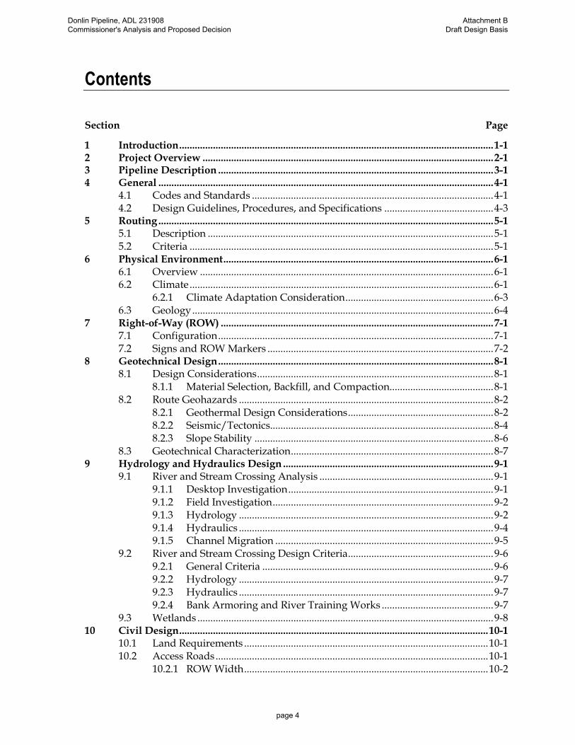
Contents
Section Page
1 Introduction ......................................................................................................................... 1-1 2 Project Overview ................................................................................................................ 2-1 3 Pipeline Description .......................................................................................................... 3-1 4 General ................................................................................................................................. 4-1
4.1 Codes and Standards ............................................................................................. 4-1 4.2 Design Guidelines, Procedures, and Specifications .......................................... 4-3
5 Routing ................................................................................................................................. 5-1 5.1 Description .............................................................................................................. 5-1 5.2 Criteria ..................................................................................................................... 5-1
6 Physical Environment ........................................................................................................ 6-1 6.1 Overview ................................................................................................................. 6-1 6.2 Climate ..................................................................................................................... 6-1
6.2.1 Climate Adaptation Consideration ......................................................... 6-3 6.3 Geology .................................................................................................................... 6-4
7 Right-of-Way (ROW) ......................................................................................................... 7-1 7.1 Configuration .......................................................................................................... 7-1 7.2 Signs and ROW Markers ....................................................................................... 7-2
8 Geotechnical Design .......................................................................................................... 8-1 8.1 Design Considerations ........................................................................................... 8-1
8.1.1 Material Selection, Backfill, and Compaction........................................ 8-1 8.2 Route Geohazards .................................................................................................. 8-2
8.2.1 Geothermal Design Considerations ........................................................ 8-2 8.2.2 Seismic/Tectonics...................................................................................... 8-4 8.2.3 Slope Stability ............................................................................................ 8-6
8.3 Geotechnical Characterization .............................................................................. 8-7 9 Hydrology and Hydraulics Design ................................................................................. 9-1
9.1 River and Stream Crossing Analysis ................................................................... 9-1 9.1.1 Desktop Investigation ............................................................................... 9-1 9.1.2 Field Investigation ..................................................................................... 9-2 9.1.3 Hydrology .................................................................................................. 9-2 9.1.4 Hydraulics .................................................................................................. 9-4 9.1.5 Channel Migration .................................................................................... 9-5
9.2 River and Stream Crossing Design Criteria ........................................................ 9-6 9.2.1 General Criteria ......................................................................................... 9-6 9.2.2 Hydrology .................................................................................................. 9-7 9.2.3 Hydraulics .................................................................................................. 9-7 9.2.4 Bank Armoring and River Training Works ........................................... 9-7
9.3 Wetlands .................................................................................................................. 9-8 10 Civil Design ....................................................................................................................... 10-1
10.1 Land Requirements .............................................................................................. 10-1 10.2 Access Roads ......................................................................................................... 10-1
10.2.1 ROW Width .............................................................................................. 10-2
Donlin Pipeline, ADL 231908 Commissioner's Analysis and Proposed Decision
Attachment B Draft Design Basis
page 4

10.2.2 Section ....................................................................................................... 10-2 10.3 Airfields and Helipads......................................................................................... 10-3 10.4 Material Sites ......................................................................................................... 10-3
10.4.1 Selection .................................................................................................... 10-3 10.4.2 Permitting ................................................................................................. 10-4
10.5 Drainage and Erosion Control ............................................................................ 10-6 10.5.1 General Criteria ....................................................................................... 10-6 10.5.2 Hydrology ................................................................................................ 10-7 10.5.3 Hydraulics ................................................................................................ 10-7 10.5.4 Storm Water Management ..................................................................... 10-7 10.5.5 Erosion Control ........................................................................................ 10-8
10.6 Restoration ........................................................................................................... 10-11 10.7 Survey .................................................................................................................. 10-11
10.7.1 Pre-Construction Survey ...................................................................... 10-12 10.7.2 Construction Survey and Staking ....................................................... 10-12 10.7.3 As-Built Survey ...................................................................................... 10-12 10.7.4 Field Survey Methods ........................................................................... 10-12 10.7.5 Control Monuments .............................................................................. 10-13 10.7.6 Survey Data Management .................................................................... 10-13
11 Pipeline Design................................................................................................................. 11-1 11.1 Gas Composition .................................................................................................. 11-1 11.2 Pipeline Hydraulics .............................................................................................. 11-1 11.3 Class Location ....................................................................................................... 11-3 11.4 Minimum Cover ................................................................................................... 11-4 11.5 Ditch Modes .......................................................................................................... 11-4
11.5.1 Normal Soil .............................................................................................. 11-4 11.5.2 Consolidated Rock .................................................................................. 11-5
11.6 General Design Data ............................................................................................ 11-6 11.7 Pipeline Materials ................................................................................................. 11-7
11.7.1 Line Pipe ................................................................................................... 11-7 11.7.2 Valves ........................................................................................................ 11-8 11.7.3 Flanges and Fittings ................................................................................ 11-8
11.8 Pipeline Appurtenances ...................................................................................... 11-8 11.8.1 Overpressure Protection ......................................................................... 11-8 11.8.2 Mainline Block Valves ............................................................................ 11-9 11.8.3 Launchers and Receivers ........................................................................ 11-9 11.8.4 Beluga Pipeline Tie-in ........................................................................... 11-10
11.9 Bending ................................................................................................................ 11-10 11.9.1 Field Bends ............................................................................................. 11-10 11.9.2 Induction Bends ..................................................................................... 11-11 11.9.3 HDD Bends............................................................................................. 11-11
11.10 Welding ................................................................................................................ 11-11 11.11 Buoyancy Control ............................................................................................... 11-11 11.12 Crossings ............................................................................................................. 11-12
11.12.1 Road Crossings ...................................................................................... 11-12 11.12.2 Water Crossings ..................................................................................... 11-12 11.12.3 Foreign Crossings .................................................................................. 11-13
Donlin Pipeline, ADL 231908 Commissioner's Analysis and Proposed Decision
Attachment B Draft Design Basis
page 5
12 Pipe Stress Analysis ......................................................................................................... 12-1 12.1 Introduction ........................................................................................................... 12-1 12.2 Classification of Loading Conditions ................................................................ 12-1 12.3 Design Loads ......................................................................................................... 12-2
12.3.1 Internal Pressure ...................................................................................... 12-2 12.3.2 Dead Load ................................................................................................ 12-3 12.3.3 Temperature Differential ........................................................................ 12-3 12.3.4 Overburden and Vehicular Loads ........................................................ 12-4 12.3.5 Buoyancy .................................................................................................. 12-5 12.3.6 Snow, Ice, and Wind Loads ................................................................... 12-5 12.3.7 Seismic Loads ........................................................................................... 12-5
12.4 Load Combinations .............................................................................................. 12-6 12.4.1 Maximum Allowable Stresses and Strains .......................................... 12-8 12.4.2 Maximum Allowable Stress Levels for Transportation and Stacking 12-
9 12.4.3 Maximum Allowable Pipe Ovalling ..................................................... 12-9 12.4.4 Elastic Stability ......................................................................................... 12-9
12.5 Strain Design Criteria........................................................................................... 12-9 12.5.1 Preliminary Strain Capacity ................................................................. 12-10 12.5.2 Strain Demand Limits ........................................................................... 12-10
12.6 Nonlinear Analyses for Buried Pipe ................................................................ 12-11 12.6.1 General .................................................................................................... 12-11 12.6.2 Input Modeling for Pipe Stress Analysis ........................................... 12-11
12.7 Differential Ground Movement........................................................................ 12-12 12.7.1 Route Characterization for Differential Displacement Studies ...... 12-12 12.7.2 Movement from Frost Heave and Thaw Settlement ........................ 12-13
12.8 Bend Analysis ..................................................................................................... 12-13 12.9 Aboveground Supports ..................................................................................... 12-14 12.10 Minimum Free Stress Installation Radius ....................................................... 12-14
13 Pressure Testing ................................................................................................................ 13-1 13.1 Hydrostatic Testing of High-Pressure Pipelines .............................................. 13-1 13.2 Cleaning and Drying ............................................................................................ 13-1 13.3 Cold-weather Testing........................................................................................... 13-1 13.4 Discharge of Hydrostatic Test Water ................................................................. 13-1 13.5 Testing with Air or Gas ....................................................................................... 13-2
14 Compressor Station .......................................................................................................... 14-1 14.1 Overview ............................................................................................................... 14-1
14.1.1 Site Location and Description ................................................................ 14-1 14.1.2 Geotechnical ............................................................................................. 14-3 14.1.3 System and Process Description ............................................................ 14-4 14.1.4 In-line Inspection and Maintenance Operations ................................. 14-1 14.1.5 Pressure and Temperature Limitations ................................................ 14-1
14.2 General ................................................................................................................... 14-2 14.2.1 Operational Philosophy .......................................................................... 14-2 14.2.2 Control Philosophy ................................................................................. 14-3 14.2.3 Fire and Gas Philosophy ........................................................................ 14-3 14.2.4 Architectural ............................................................................................ 14-4
Donlin Pipeline, ADL 231908 Commissioner's Analysis and Proposed Decision
Attachment B Draft Design Basis
page 6

14.2.5 Civil / Structural Engineering ............................................................. 14-11 14.2.6 Mechanical Engineering ....................................................................... 14-12 14.2.7 Cathodic Protection and Coating Systems ......................................... 14-13 14.2.8 Instrumentation ..................................................................................... 14-13 14.2.9 Electrical Engineering ........................................................................... 14-13
15 Metering Station ............................................................................................................... 15-1 15.1 Overview ............................................................................................................... 15-1
15.1.1 Site Location and Description ................................................................ 15-1 15.1.2 Geotechnical ............................................................................................. 15-1
15.2 General ................................................................................................................... 15-1 15.2.1 Architectural ............................................................................................ 15-2 15.2.2 Civil /Structural Engineering ................................................................ 15-3 15.2.3 Mechanical Engineering ......................................................................... 15-3 15.2.4 Instrumentation ....................................................................................... 15-5 15.2.5 Electrical Engineering ............................................................................. 15-6
16 Corrosion Control and Monitoring ............................................................................... 16-7 16.1 Cathodic Protection .............................................................................................. 16-7
16.1.1 Cathodic Isolation ................................................................................... 16-8 16.1.2 Cathodic Protection Test Leads ............................................................. 16-8
16.2 Corrosion Coatings .............................................................................................. 16-8 16.2.1 Field Joints ................................................................................................ 16-8 16.2.2 Induction Bends ....................................................................................... 16-9 16.2.3 Painting ..................................................................................................... 16-9 16.2.4 Coating at Interface ................................................................................. 16-9
17 SCADA System ................................................................................................................. 17-1 17.1 System Architecture ............................................................................................. 17-3 17.2 System Functionality ............................................................................................ 17-3 17.3 Operations Control Center .................................................................................. 17-4
17.3.1 SCADA System ........................................................................................ 17-4 17.3.2 System Databases .................................................................................... 17-7 17.3.3 Leak Detection and Emergency Response ........................................... 17-7
17.4 SCADA Security ................................................................................................... 17-9 17.5 Communications Systems ................................................................................. 17-11
17.5.1 System Components ............................................................................. 17-12 17.5.2 Fiber Optic Signal Amplification ........................................................ 17-13 17.5.3 Special Design Considerations ............................................................ 17-14 17.5.4 Security ................................................................................................... 17-15
18 Security ............................................................................................................................... 18-1 18.1 General ................................................................................................................... 18-1
18.1.1 Fencing ...................................................................................................... 18-1 18.1.2 Locks ......................................................................................................... 18-1 18.1.3 Security Surveillance ............................................................................... 18-1
18.2 Pipeline .................................................................................................................. 18-1 18.3 Metering Stations .................................................................................................. 18-2 18.4 Farewell Launcher/Receiver .............................................................................. 18-2 18.5 Compressor Station .............................................................................................. 18-2 18.6 Mainline Block Valves ......................................................................................... 18-2
Donlin Pipeline, ADL 231908 Commissioner's Analysis and Proposed Decision
Attachment B Draft Design Basis
page 7

19 Project Records .................................................................................................................. 19-1 20 References .......................................................................................................................... 20-1
Table
Table 4-1 49 CFR 192 Referenced Codes and Standards .................................................... 4-1 Table 4-2 Additional Codes and Standards ......................................................................... 4-2 Table 6-1 Mean Monthly Climate Data ................................................................................ 6-2 Table 7-1 Pipeline Marker Type and Spacing ...................................................................... 7-2 Table 8-1 Peak Ground Acceleration Values Along Pipeline Route ................................ 8-5 Table 8-2 Fault Crossing Displacement ................................................................................ 8-5 Table 10-1 Access Road Design Criteria ............................................................................... 10-2 Table 11-1 Gas Composition .................................................................................................. 11-1 Table 11-2 Hydraulic Analysis Parameters .......................................................................... 11-1 Table 11-3 Hydraulic Analyses Results ................................................................................ 11-2 Table 11-4 Minimum Cover Requirements .......................................................................... 11-4 Table 11-5 Pipeline Design Criteria....................................................................................... 11-6 Table 12-1 Load Combinations for Buried Pipe .................................................................. 12-7 Table 12-2 Load Combinations for Aboveground Pipe ..................................................... 12-7 Table 12-3 Allowable Stresses in Buried Pipe...................................................................... 12-8 Table 12-4 Allowable Stresses Aboveground Pipe ............................................................. 12-8 Table 12-5 Preliminary Longitudinal Strain Capacities ................................................... 12-10 Table 12-6 Preliminary Longitudinal Strain Demand Limits .......................................... 12-10 Table 14-1 Monthly Climate Summary—Beluga, AK ........................................................ 14-2 Table 14-2 Natural Gas Process Conditions ......................................................................... 14-2 Table 16-1 Pipeline Corrosion Protection Requirements ................................................... 16-7 Table 16-2 Pipeline Coating Thicknesses ............................................................................. 16-8 Table 17-1 Probability vs Consequence Security Assurance Level (SAL) Level .......... 17-10
Figure
Figure 2-1 Proposed Pipeline Route ....................................................................................... 2-1 Figure 6-1 MAAT Data and Trends ........................................................................................ 6-3 Figure 7-1 Typical ROW Section ............................................................................................. 7-1 Figure 8-1 Bedding and Padding Gradations........................................................................ 8-1 Figure 8-2 Weather Stations Used for Determining Summer and Winter Ambient Air Temperatures 8-8 Figure 8-3 Temperature Data along the Pipeline Route ...................................................... 8-9 Figure 11-1 Typical Ditch Section ........................................................................................... 11-5 Figure 11-2 Schematic of a Typical Watercourse Crossing ............................................... 11-13 Figure 14-1 Compressor Station Location Map .................................................................... 14-2 Figure 14-2 Preliminary Compressor Station Layout .......................................................... 14-1 Figure 17-1 SCADA Network Schematic ............................................................................... 17-2
Donlin Pipeline, ADL 231908 Commissioner's Analysis and Proposed Decision
Attachment B Draft Design Basis
page 8
Abbreviations
°F degrees Fahrenheit
AAC Alaska Administrative Code
AASHTO American Association of State Highway and Transportation Officials
ADEC Alaska Department of Environmental Conservation
ADF&G Alaska Department of Fish and Game
ADNR Alaska Department of Natural Resources
ADOT&PF Alaska Department of Transportation and Public Facilities
AISC American Institute of Steel Construction
ALA American Lifelines Alliance
API American Petroleum Institute
ASME American Society of Mechanical Engineers International
ANSI American National Standards Institute
ARO abrasion-resistant overlay
ASTM American Society for Testing and Materials
AWC Anadromous Waters Catalog
BLM Bureau of Land Management
BPL Beluga natural gas pipeline
CCTV closed-circuit television
CFR Code of Federal Regulations
CN curve number
CP cathodic protection
CRES Center for Reliable Energy Systems
dB decibel
DBM design basis memorandum
DOT U.S. Department of Transportation
Donlin Gold Donlin Gold LLC
ENSTAR ENSTAR Natural Gas Company
EPA U.S. Environmental Protection Agency
ESD emergency shutdown
FBE fusion-bonded epoxy
Donlin Pipeline, ADL 231908 Commissioner's Analysis and Proposed Decision
Attachment B Draft Design Basis
page 9

FHWA Federal Highway Administration
FOC fiber optic cable
ft feet
GIS geographical information system
GPS global positioning system
GTI Gas Technology Institute (formerly Gas Research Institute [GRI])
H&V heating and ventilation
HDD horizontal directional drill
IBC International Building Code
IDW inverse distance weighted
IP Internet Protocol
IFC International Fire Code
IMC International Mechanical Code
km kilometers
LAN local area network
LDS leak detection system
LiDAR light detection and ranging
LEL lower explosive limit
M magnitude
m meters
MAAT mean annual air temperature
MAOP maximum allowable operating pressure
MCC mine control center
MCE maximum credible earthquake
MLV mainline block valve
mm millimeter
MMscfd million standard cubic feet per day
MOA Memorandum of Agreement
MP milepost
MSS Manufacturers Standardization Society of the Valve and Fittings Industry
MW moment magnitude
NACE NACE International
Donlin Pipeline, ADL 231908 Commissioner's Analysis and Proposed Decision
Attachment B Draft Design Basis
page 10
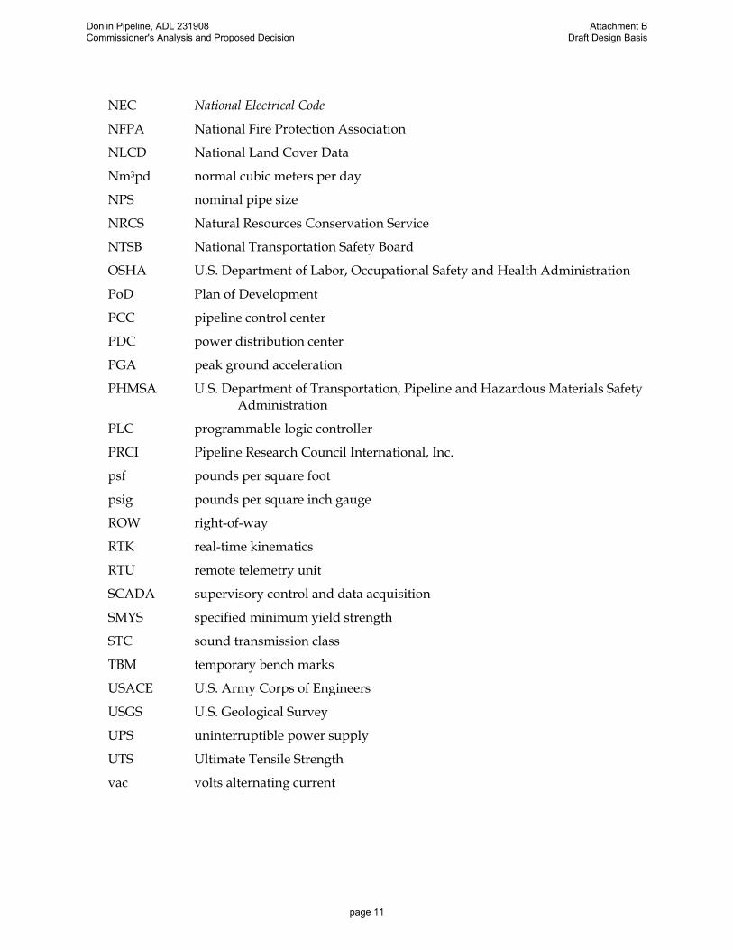
NEC National Electrical Code
NFPA National Fire Protection Association
NLCD National Land Cover Data
Nm3pd normal cubic meters per day
NPS nominal pipe size
NRCS Natural Resources Conservation Service
NTSB National Transportation Safety Board
OSHA U.S. Department of Labor, Occupational Safety and Health Administration
PoD Plan of Development
PCC pipeline control center
PDC power distribution center
PGA peak ground acceleration
PHMSA U.S. Department of Transportation, Pipeline and Hazardous Materials Safety Administration
PLC programmable logic controller
PRCI Pipeline Research Council International, Inc.
psf pounds per square foot
psig pounds per square inch gauge
ROW right-of-way
RTK real-time kinematics
RTU remote telemetry unit
SCADA supervisory control and data acquisition
SMYS specified minimum yield strength
STC sound transmission class
TBM temporary bench marks
USACE U.S. Army Corps of Engineers
USGS U.S. Geological Survey
UPS uninterruptible power supply
UTS Ultimate Tensile Strength
vac volts alternating current
Donlin Pipeline, ADL 231908 Commissioner's Analysis and Proposed Decision
Attachment B Draft Design Basis
page 11
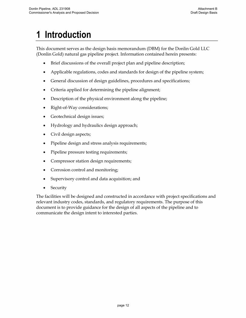
1 Introduction
This document serves as the design basis memorandum (DBM) for the Donlin Gold LLC (Donlin Gold) natural gas pipeline project. Information contained herein presents:
• Brief discussions of the overall project plan and pipeline description;
• Applicable regulations, codes and standards for design of the pipeline system;
• General discussion of design guidelines, procedures and specifications;
• Criteria applied for determining the pipeline alignment;
• Description of the physical environment along the pipeline;
• Right-of-Way considerations;
• Geotechnical design issues;
• Hydrology and hydraulics design approach;
• Civil design aspects;
• Pipeline design and stress analysis requirements;
• Pipeline pressure testing requirements;
• Compressor station design requirements;
• Corrosion control and monitoring;
• Supervisory control and data acquisition; and
• Security
The facilities will be designed and constructed in accordance with project specifications and relevant industry codes, standards, and regulatory requirements. The purpose of this document is to provide guidance for the design of all aspects of the pipeline and to communicate the design intent to interested parties.
Donlin Pipeline, ADL 231908 Commissioner's Analysis and Proposed Decision
Attachment B Draft Design Basis
page 12

2 Project Overview
The proposed Donlin Gold pipeline project will consist of a 14-inch diameter, dedicated natural gas transmission pipeline and a single compressor station. The pipeline will be a contract carrier, as opposed to a common carrier, meaning Donlin Gold can refuse to transport gas for other users. The system will receive natural gas from the existing ENSTAR Natural Gas Company (ENSTAR) 20-inch (508 mm) diameter pipeline (Beluga natural gas pipeline [BPL]) near Beluga, Alaska, and transport the product to the proposed Donlin Gold mine. The gas will be used to generate electricity to power industrial equipment at the mine. A map of the proposed pipeline project route is presented in Figure 2-1.
The project will include metering at the ENSTAR BPL tie-in and at the Donlin Gold mine, a compressor station, in-line inspection and maintenance tool launching and receiving facilities, a minimum of 16 mainline block valves (MLV), cathodic protection, leak detection, and supervisory control.
The installation of a fiber optic cable (including a repeater station) within the pipeline right-of-way will require a separate right-of-way application. An electrical cable will be buried adjacent to Pretty Creek road from the compressor station to the BPL tie-in to supply power for the metering module.
A separate right-of-way will be applied for within the permanent pipeline right-of-way for installation of a fiber optic cable including a repeater station. An electrical cable will be buried adjacent to Pretty Creek road from the compressor station to the BPL tie-in to supply power for the metering module.
A Plan of Development (PoD) has been prepared by Donlin Gold to support the planning and development of the proposed Donlin Gold Natural Gas Pipeline project. The PoD provides detailed information to support permit applications, preparation of the National Environmental Policy Act documents, and National Historic Preservation Act and other appropriate and/or necessary federal, state, or local regulatory processes.
The PoD also outlines the pipeline Right-of-Way (ROW) stabilization, rehabilitation, and reclamation actions. The Stabilization, Rehabilitation, and Reclamation Plan, when completed, will include mitigation measures for erosion and sediment control, as well as specifics of stabilization, rehabilitation, and reclamation actions during construction, operation and maintenance, and project termination.
Donlin Pipeline, ADL 231908 Commissioner's Analysis and Proposed Decision
Attachment B Draft Design Basis
page 13

Figure 2-1 Proposed Pipeline Route
Donlin Pipeline, ADL 231908 Commissioner's Analysis and Proposed Decision
Attachment B Draft Design Basis
page 14

3 Pipeline Description
The Donlin Gold pipeline, approximately 315 miles (507 km) long, will connect with the BPL (natural gas source) at a tie-in location within the Susitna Flats State Game Refuge in the Matanuska-Susitna Borough. The pipeline will extend to the Donlin Gold mine located in Southwest Alaska about 10 miles (16 km) north of the village of Crooked Creek on the Kuskokwim River. The pipeline route crosses an area with no significant preexisting infrastructure and does not follow any existing utility corridors.
This 14-inch (356 mm) diameter pipeline will be designed to operate at a maximum allowable operating pressure (MAOP) of 1,480 pounds per square inch gauge (psig) with a maximum throughput of approximately 76 million standard cubic feet per day (MMscfd) of natural gas (2.2 million normal cubic meters per day [Nm3pd]). A single compressor station located at approximately Milepost (MP) 0.4 of the pipeline will be required to boost the gas pressure to a level sufficient to deliver the gas to the pipeline terminus at a minimum pressure of 100 psig. The compressor station will be accessible by utilizing the existing Pretty Creek Road. No additional compression along the pipeline route will be required.
The pipeline will be regulated by the U.S. Department of Transportation (DOT) under Title 49 of the Code of Federal Regulations, Part 192 – Transportation of Natural Gas and Other Gas by Pipeline: Minimum Federal Safety Standards (49 CFR 192). The pipeline will be designed, constructed, and operated in accordance with the applicable requirements of 49 CFR 192 and will incorporate launching and receiving facilities for in-line maintenance and inspection tools, MLV, cathodic protection, leak detection, and a supervisory control and data acquisition (SCADA) system. A fiber optic cable will also be installed along the pipeline route to the mine. The point of origin of the fiber optic cable and the requirement for, and location of a repeater station, will be determined during final engineering design.
The engineering design life of the proposed pipeline is 30 years. As used herein, engineering design life is defined as the period over which the systems, components, and structure are required to perform their primary functions with acceptable safety, regulatory and environmental performance, and with acceptable probability they will not experience large failures, require extensive replacements, or need significant repairs. All time-dependent calculations utilize this 30-year period for design analysis.
Donlin Pipeline, ADL 231908 Commissioner's Analysis and Proposed Decision
Attachment B Draft Design Basis
page 15
4 General
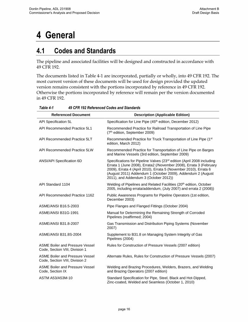
4.1 Codes and Standards
The pipeline and associated facilities will be designed and constructed in accordance with 49 CFR 192.
The documents listed in Table 4-1 are incorporated, partially or wholly, into 49 CFR 192. The most current version of these documents will be used for design provided the updated version remains consistent with the portions incorporated by reference in 49 CFR 192. Otherwise the portions incorporated by reference will remain per the version documented in 49 CFR 192.
Table 4-1 49 CFR 192 Referenced Codes and Standards
Referenced Document Description (Applicable Edition)
API Specification 5L Specification for Line Pipe (45th edition, December 2012)
API Recommended Practice 5L1 Recommended Practice for Railroad Transportation of Line Pipe (7th edition, September 2009)
API Recommended Practice 5LT Recommended Practice for Truck Transportation of Line Pipe (1st edition, March 2012)
API Recommended Practice 5LW Recommended Practice for Transportation of Line Pipe on Barges and Marine Vessels (3rd edition, September 2009)
ANSI/API Specification 6D Specifications for Pipeline Valves (23rd edition (April 2008 including Errata 1 (June 2008), Errata2 (/November 2008), Errata 3 (February 2009), Errata 4 (April 2010), Errata 5 (November 2010), Errata 6 (August 2011) Addendum 1 (October 2009), Addendum 2 (August 2011), and Addendum 3 (October 2012))
API Standard 1104 Welding of Pipelines and Related Facilities (20th edition, October 2005, including errata/addendum, (July 2007) and errata 2 (2008))
API Recommended Practice 1162 Public Awareness Programs for Pipeline Operators (1st edition, December 2003)
ASME/ANSI B16.5-2003 Pipe Flanges and Flanged Fittings (October 2004)
ASME/ANSI B31G-1991 Manual for Determining the Remaining Strength of Corroded Pipelines (reaffirmed; 2004)
ASME/ANSI B31.8-2007 Gas Transmission and Distribution Piping Systems (November 2007)
ASME/ANSI B31.8S-2004 Supplement to B31.8 on Managing System Integrity of Gas Pipelines (2004)
ASME Boiler and Pressure Vessel Code, Section VIII, Division 1
Rules for Construction of Pressure Vessels (2007 edition)
ASME Boiler and Pressure Vessel Code, Section VIII, Division 2
Alternate Rules, Rules for Construction of Pressure Vessels (2007)
ASME Boiler and Pressure Vessel Code, Section IX
Welding and Brazing Procedures, Welders, Brazers, and Welding and Brazing Operators (2007 edition)
ASTM A53/A53M-10 Standard Specification for Pipe, Steel, Black and Hot-Dipped, Zinc-coated, Welded and Seamless (October 1, 2010)
Donlin Pipeline, ADL 231908 Commissioner's Analysis and Proposed Decision
Attachment B Draft Design Basis
page 16
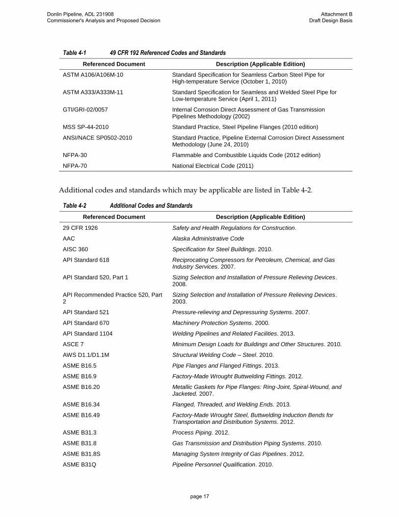
Table 4-1 49 CFR 192 Referenced Codes and Standards
Referenced Document Description (Applicable Edition)
ASTM A106/A106M-10 Standard Specification for Seamless Carbon Steel Pipe for High-temperature Service (October 1, 2010)
ASTM A333/A333M-11 Standard Specification for Seamless and Welded Steel Pipe for Low-temperature Service (April 1, 2011)
GTI/GRI-02/0057 Internal Corrosion Direct Assessment of Gas Transmission Pipelines Methodology (2002)
MSS SP-44-2010 Standard Practice, Steel Pipeline Flanges (2010 edition)
ANSI/NACE SP0502-2010 Standard Practice, Pipeline External Corrosion Direct Assessment Methodology (June 24, 2010)
NFPA-30 Flammable and Combustible Liquids Code (2012 edition)
NFPA-70 National Electrical Code (2011)
Additional codes and standards which may be applicable are listed in Table 4-2.
Table 4-2 Additional Codes and Standards
Referenced Document Description (Applicable Edition)
29 CFR 1926 Safety and Health Regulations for Construction.
AAC Alaska Administrative Code
AISC 360 Specification for Steel Buildings. 2010.
API Standard 618 Reciprocating Compressors for Petroleum, Chemical, and Gas Industry Services. 2007.
API Standard 520, Part 1 Sizing Selection and Installation of Pressure Relieving Devices. 2008.
API Recommended Practice 520, Part 2
Sizing Selection and Installation of Pressure Relieving Devices. 2003.
API Standard 521 Pressure-relieving and Depressuring Systems. 2007.
API Standard 670 Machinery Protection Systems. 2000.
API Standard 1104 Welding Pipelines and Related Facilities. 2013.
ASCE 7 Minimum Design Loads for Buildings and Other Structures. 2010.
AWS D1.1/D1.1M Structural Welding Code – Steel. 2010.
ASME B16.5 Pipe Flanges and Flanged Fittings. 2013.
ASME B16.9 Factory-Made Wrought Buttwelding Fittings. 2012.
ASME B16.20 Metallic Gaskets for Pipe Flanges: Ring-Joint, Spiral-Wound, and Jacketed. 2007.
ASME B16.34 Flanged, Threaded, and Welding Ends. 2013.
ASME B16.49 Factory-Made Wrought Steel, Buttwelding Induction Bends for Transportation and Distribution Systems. 2012.
ASME B31.3 Process Piping. 2012.
ASME B31.8 Gas Transmission and Distribution Piping Systems. 2010.
ASME B31.8S Managing System Integrity of Gas Pipelines. 2012.
ASME B31Q Pipeline Personnel Qualification. 2010.
Donlin Pipeline, ADL 231908 Commissioner's Analysis and Proposed Decision
Attachment B Draft Design Basis
page 17

Table 4-2 Additional Codes and Standards
Referenced Document Description (Applicable Edition)
ASME Boiler and Pressure Vessel Code, Section VIII, Division 1
Rules for the Construction of Pressure Vessels. 2013.
ASME Boiler and Pressure Vessel Code, Section VIII, Division 2
Rules for the Construction of Pressure Vessels – Alternative Rules. 2013
ASME Boiler and Pressure Vessel Code, Section IX
Welding and Brazing Qualifications. 2013
ASME B30.2 Overhead and Gantry Cranes (Top Running Bridge, Single or Multiple Girder, Top Running Trolley Hoist. 2011.
ASME B30.11 Monorails and Underhung Cranes. 2010.
ASME B30.16 Overhead Hoists. 2012.
ASME B30.17 Overhead and Gantry Cranes (Top Running Bridge, Single Girder, Underhung Hoist). 2006 (reaffirmed 2012).
IBC International Building Code. 2015.
IEEE-SA National Electric Safety Code. Latest edition.
IES The Lighting Handbook. 10th edition.
IFC International Fire Code (IFC). 2015.
IMC International Mechanical Code (IMC). 2015.
NFPA 70 National Electrical Code. Latest edition.
NFPA 72 National Fire Alarm and Signaling Code. 2013.
NFPA 497 Recommended Practice for the Classification of Flammable Liquids, Gases, or Vapors and of Hazardous (Classified) Locations for Electrical Installations in Chemical Process Areas. 2012.
NFPA 780 Installation of Lightning Protection Systems. 2014.
4.2 Design Guidelines, Procedures, and Specifications
Project guidelines, procedures, and specifications will be developed during design to supplement or expand applicable industry codes, standards, and regulations. These documents will fall into the following categories and will cover construction, design, inspection, materials, and procurement:
• Civil/Structural/Architectural
• Corrosion and Coating
• Electrical
• Fire and Gas
• Instrumentation/Controls
• Mechanical Equipment
• Mechanical Piping
Donlin Pipeline, ADL 231908 Commissioner's Analysis and Proposed Decision
Attachment B Draft Design Basis
page 18

• Welding and Fabrication
• Safety, Health, and Environmental
Donlin Pipeline, ADL 231908 Commissioner's Analysis and Proposed Decision
Attachment B Draft Design Basis
page 19

5 Routing
The pipeline route has been located and evaluated based on available technical, environmental, cultural, land ownership, and economic considerations. The criteria discussed in this section address these considerations.
5.1 Description
The pipeline will originate at the west end of the Beluga Gas Field, approximately 30 miles northwest of Anchorage. The route initiates at the BPL, within the SFSGR, and receives booster compression at approximately MP 0.4. The route then proceeds north, traversing the east flank of Little Mount Susitna to the Skwentna River (approximately MP 50) and then parallels the Skwentna River in a westerly direction to Puntilla Lake (approximately MP 102).
From approximately MP 106 the route trends northwest before turning north into the broad valley of the Threemile Creek. At approximately MP 114.5 the alignment trends westerly as it approaches an unnamed pass in the Alaska Range divide. This pass has an elevation of 3,870 ft (1,179.6 m). The short steep drainages immediately on each side of the pass are in narrow valleys with talus lobes and stabilized rock glaciers at the base of steep rock slopes. Here the pipeline utilizes benches above the creeks that flow from the pass. At approximately MP 120.5 the pipeline route enters a typical broad “U” shaped valley characteristic of the glacial valleys in this region. As the pipeline route descends this valley, it is typically on the benches or terraces with moderate to little slope that border this unnamed tributary of the Tatina River.
At approximately MP 127.3, the route crosses the Tatina River’s glacial braided floodplain before it ascends to a broad open pass before descending into the valley of the Jones River at approximately MP 130.5. From approximately MP 130.5 to MP 143, the pipeline route remains in the Jones River Valley and roughly parallels the Jones River. The route crosses the Jones River twice at approximately MP 136.6 and MP 137.6. The pipeline route exits the mountains of the Alaska Range at approximately MP 143 heading westerly crossing the South Fork of the Kuskokwim River then trending southwesterly towards Farewell.
The route continues southwest near Farewell (approximately MP 157), paralleling the Alaska Range until crossing the Kuskokwim River (between approximately MP 240 and MP 241). Beyond the Kuskokwim River, the route primarily follows ridgelines for more than 80 miles toward the west, to the mine site terminus (MP 315), approximately 10 miles north of the village of Crooked Creek, Alaska.
5.2 Criteria
Selection of the most feasible route involved consideration of the following general criteria:
• Minimization of the total pipeline length
• Minimization of water and wetlands crossings
• Avoidance of geotechnical hazards
Donlin Pipeline, ADL 231908 Commissioner's Analysis and Proposed Decision
Attachment B Draft Design Basis
page 20

• Avoidance of hydrological hazards
• Avoidance of known areas of environmental and cultural concern, including known wetlands and cultural resource sites
• Avoidance of areas with potential land use conflicts
• Optimization of seasonal construction schedules
• Minimization of areas of steep slopes, permafrost terrain, marshes and bogs, river crossings, difficult access, and other areas of challenging construction
• Minimization of visual impacts
Donlin Pipeline, ADL 231908 Commissioner's Analysis and Proposed Decision
Attachment B Draft Design Basis
page 21

6 Physical Environment
6.1 Overview
Topographical relief along the primary route includes flat lying plains and muskeg (5 percent), moderately rolling hills and rolling alpine ridges (70 percent) and mountainous areas (25 percent). Much of the flat lying terrain is interspersed within portions of the alignment that are dominated by rolling or mountainous landforms.
Vegetation along the prime route consists of a mixture of deciduous trees (cottonwood, alder, aspen, and birch) and evergreens (white and black spruce) that cover approximately 60 percent of the route in roughly equal proportions of dense, moderately dense, and light stands. The remaining 40 percent of the route is primarily lightly vegetated with alpine species such as moss, lichens, and low bushes along the ridges of dendritically drained hills between the Kuskokwim River and the mine site, and in Jones Pass. The northern outwash slopes of the Alaska Range and the Happy River Valley are covered with a thick layer of moss and dwarf bushes.
Surficial soils consist primarily of undifferentiated glacial tills, extensive sand and gravel deposits, sporadic boulders, and minor bedrock outcrops. Traditional pipeline construction techniques will be suitable in these materials. Permafrost is present throughout the mountains at higher elevations, along the northern flank of the Alaska Range, and along the alpine ridge near the mine site. Approximately 40 percent of the route has been estimated to have shallow groundwater (less than 5 ft below ground surface) or significant wet, organic deposits. Numerous stream crossings are present that will require special consideration during design and construction.
6.2 Climate
The climate in the vicinity of the southern portion of the pipeline (Beluga to Skwentna) is mild by Alaskan standards because of proximity to seacoast. Daytime temperatures in summer average between 55 degrees Fahrenheit (°F) and 75°F, with occasional hotter days. Winter temperatures can drop as low as –40°F but typically range from –15°F to 30°F. On average, this area receives 16 inches of precipitation per year, with approximately 75 inches of snow, although there are areas in the southcentral portion of the study area that receive far more snow. The climate is classified as subarctic with representative average monthly temperatures shown in Table 6-1 for Beluga and Skwentna.
The climate of the central portion of the pipeline route (Skwentna to Farewell) is heavily influenced by the Alaska Range through which it runs. Representative average monthly temperatures in the area are presented in Table 6-1 for Hayes River and Puntilla. Daytime temperatures in the Alaska Range during summer range from 45°F to 65°F; winter temperatures typically range from –5°F to 25°F.
The climate of the western portion of the pipeline route (from Farewell to the mine site) is determined, in large part, by weather from the Bering Sea and cold fronts from the arctic. This climate is a subarctic oceanic climate in the southwestern portion of the area and a continental subarctic climate farther inland. Representative average monthly temperatures in the region as reported by the Western Regional Climate Center
Donlin Pipeline, ADL 231908 Commissioner's Analysis and Proposed Decision
Attachment B Draft Design Basis
page 22
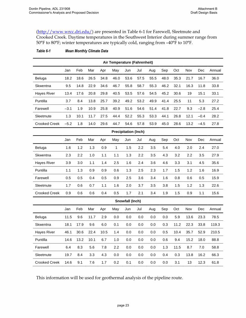
(http://www.wrcc.dri.edu/) are presented in Table 6-1 for Farewell, Sleetmute and Crooked Creek. Daytime temperatures in the Southwest Interior during summer range from 50°F to 80°F; winter temperatures are typically cold, ranging from –40°F to 10°F.
Table 6-1 Mean Monthly Climate Data
Air Temperature (Fahrenheit)
Jan Feb Mar Apr May Jun Jul Aug Sep Oct Nov Dec Annual
Beluga 18.2 18.6 26.5 34.8 46.0 53.6 57.5 55.5 48.0 35.3 21.7 16.7 36.0
Skwentna 9.5 14.8 22.9 34.6 46.7 55.8 58.7 55.3 46.2 32.1 16.3 11.8 33.8
Hayes River 13.4 17.6 20.8 29.8 40.5 53.5 57.6 54.5 45.2 30.6 19 15.1 33.1
Puntilla 3.7 8.4 13.8 25.7 39.2 49.2 53.2 49.9 41.4 25.5 11 5.3 27.2
Farewell –3.1 1.9 10.9 25.8 40.9 51.6 54.6 51.4 41.8 22.7 9.3 –2.8 25.4
Sleetmute 1.3 10.1 11.7 27.5 44.4 52.2 55.3 53.3 44.1 26.8 12.1 –0.4 28.2
Crooked Creek –5.2 1.8 14.0 29.6 44.7 54.6 57.8 53.9 45.0 28.6 13.2 –4.5 27.8
Precipitation (Inch)
Jan Feb Mar Apr May Jun Jul Aug Sep Oct Nov Dec Annual
Beluga 1.6 1.2 1.3 0.9 1 1.5 2.2 3.5 5.4 4.0 2.0 2.4 27.0
Skwentna 2.3 2.2 1.0 1.1 1.1 1.3 2.2 3.5 4.3 3.2 2.2 3.5 27.9
Hayes River 3.9 3.0 1.1 1.4 2.5 1.6 2.4 3.6 4.6 3.3 3.1 4.5 35.6
Puntilla 1.1 1.3 0.9 0.9 0.6 1.3 2.5 2.3 1.7 1.5 1.2 1.6 16.9
Farewell 0.5 0.5 0.4 0.5 0.9 2.5 3.6 3.4 1.6 0.8 0.6 0.5 15.9
Sleetmute 1.7 0.6 0.7 1.1 1.6 2.0 3.7 3.5 3.8 1.5 1.2 1.3 22.6
Crooked Creek 0.9 0.6 0.6 0.4 0.5 1.7 2.1 3.4 1.9 1.5 0.9 1.1 15.6
Snowfall (Inch)
Jan Feb Mar Apr May Jun Jul Aug Sep Oct Nov Dec Annual
Beluga 11.5 9.6 11.7 2.9 0.0 0.0 0.0 0.0 0.0 5.9 13.6 23.3 78.5
Skwentna 18.1 17.9 9.6 6.0 0.1 0.0 0.0 0.0 0.3 11.2 22.3 33.8 119.3
Hayes River 46.1 30.6 22.4 10.5 1.4 0.0 0.0 0.0 0.5 10.4 35.7 52.9 210.5
Puntilla 14.6 13.2 10.1 6.7 1.0 0.0 0.0 0.0 0.6 9.4 15.2 18.0 88.8
Farewell 6.4 8.3 5.6 7.8 2.2 0.0 0.0 0.0 1.3 11.5 8.7 7.0 58.8
Sleetmute 19.7 8.4 3.3 4.3 0.0 0.0 0.0 0.0 0.4 0.3 13.8 16.2 66.3
Crooked Creek 14.6 9.1 7.6 1.7 0.2 0.1 0.0 0.0 0.0 3.1 13 12.3 61.8
This information will be used for geothermal analysis of the pipeline route.
Donlin Pipeline, ADL 231908 Commissioner's Analysis and Proposed Decision
Attachment B Draft Design Basis
page 23

6.2.1 Climate Adaptation Consideration
Mean annual air temperature (MAAT) data was obtained from the Western Regional Climate Center for three stations in the vicinity of the pipeline having relatively complete data: McGrath (1941 – 2014), Puntilla (1942 – 2014, missing 2008), and Skwentna (1939 – 1959, 1970 – 1975, 1979 – 1991, 1993 – 2014). Individual years with more than five months missing more than five days of data were excluded from consideration. Linear least squares
fits were applied to each set of data, yielding slopes of approximately 0.04F/year,
0.04F/year, and 0.02F/year, for McGrath, Puntilla, and Skwentna, respectively. The MAAT data for each station along with the linear least squares fit are presented graphically in Figure 6-1.
Figure 6-1 MAAT Data and Trends
Based on this data, conservatively an increase in MAAT of 0.04F/year will be incorporated into the planning, design, construction, operations and maintenance, and reclamation considerations for the project.
Donlin Pipeline, ADL 231908 Commissioner's Analysis and Proposed Decision
Attachment B Draft Design Basis
page 24

6.3 Geology
The general geology of the alignment is composed of alluvium, colluvium, and glacial till over bedrock. The depth to bedrock is highly variable, exceeding hundreds of feet in the coastal area and exposed at the ground surface in the Alaska Range. Where exposed, the rock generally is composed of granite, sandstone, siltstone, mudstone, and limestone.
Near-surface soil deposits vary considerably along the pipeline corridor, based on proximity to the coastline, mountains slopes, and river floodplains.
• Surficial soils primarily consist of unconsolidated silt, sand, and gravel of fluvial, glacial, colluvial, and other origins from the coast at Cook Inlet to the Alaska Range.
• Through the Alaska Range, there are numerous areas of sand and gravel deposits originating from stream and slope wash depositions.
• Along the northern flank of the Alaska Range eastward from Farewell, there are extensive sand-and-gravel outwash deposits interspersed with undifferentiated silt till lobes left behind by retreating glaciers. Some of these ablation tills may contain large boulders, commonly called “glacial erratics.”
• From Farewell to Big River, the composition of surficial soils is similar to those in the Cook Inlet area.
• West of Big River, soils are primarily residual weathering products of the underlying bedrock that have been transported downslope to form a mixture of silt, sand, and gravel colluvium.
• The dendritic hill ridge tops westward from the Kuskokwim River generally consist of an unconsolidated mantle of residual soil derived from in-place weathering of the underlying bedrock (sandstone, siltstone, shale, and conglomerates). The soil is generally a heterogeneous mixture of silt, sand, angular gravel, and frost-shattered rock. Permafrost is present through the mountains at higher elevations, along the northern flank of the Alaska Range, and along the alpine ridge near the mine site.
Donlin Pipeline, ADL 231908 Commissioner's Analysis and Proposed Decision
Attachment B Draft Design Basis
page 25

7 Right-of-Way (ROW)
7.1 Configuration
Donlin Gold has identified a construction planning corridor of 300 feet (91.4 m) within which it will apply for authorization for a 150-foot (45.7 m) temporary construction ROW encompassing the 50-foot (15.2 m) permanent ROW (51-foot 2-inches [15.6 m] on Bureau of Land Management [BLM] Lands). The width of the construction corridor will vary depending on cross-slope, as well as for site-specific reasons as discussed below.
The construction corridor will be cleared as required, nominally 100 feet (30.5 m) within the authorized 150 feet (45.7 m) comprised of a 35-foot (10.7 m) spoil side and a 65-foot (19.8 m) working side (using pipe centerline as the dividing line, see Figure 7-1). The spoil side must be wide because the trench spoil must be kept low and wide to prevent it from causing snow to drift on the ROW or into the trench even though the process during winter seasons will be to immediately backfill where pipe has been placed. The only pipe not backfilled during typical installations is the length of pipe required to successfully make a tie-in weld to the next section of pipe to be installed in the trench. Stabilization, rehabilitation and reclamation activities will be performed concurrently or as soon as conditions allow.
Figure 7-1 Typical ROW Section
Donlin Pipeline, ADL 231908 Commissioner's Analysis and Proposed Decision
Attachment B Draft Design Basis
page 26

Donlin Gold will also clear temporary extra workspace as required. If the extra temporary workspace will be outside the authorized construction corridor, Donlin Gold will request a variance for the additional work space. Additional work space may be needed at the following locations:
• Stream and river crossings and high banks at ravines where earth cuts are required
• Areas where pipe is being installed using Horizontal Directional Drilling (HDD) methods to accommodate extra equipment
• Sidebends
• The beginning and end of each construction spread for spread mobilization and demobilization
• Stringing truck turnaround areas
• Extra space for spoil storage and construction activities
• Areas where high water table might undermine trench walls, creating an extra-wide trench and larger spoil piles (for instance, in a gravel floodplain)
• On steep grades or for shoofly access roads around such grades
• Pipe laydown areas
Additional workspace may be restricted at sensitive environmental or cultural areas.
Temporary access roads will be 24 feet wide or narrower, where needed, with appropriate temporary use areas as specified by engineering or construction personnel.
7.2 Signs and ROW Markers
Signs will be placed along the pipeline in compliance with regulatory requirements, including locations required by 49 CFR 192, warning the public of associated hazards and providing the operator’s name and 24-hour–a-day contact information or as additionally determined appropriate by Donlin Gold for safety purposes. Carsonite-type markers will be used for all line marking. Types of pipeline markers, and associated spacing, are presented in Table 7-1.
Table 7-1 Pipeline Marker Type and Spacing
Sign Location
Aerial markers Every 1 mile
Warning/marker signs Both sides of rivers
Line-of-sight spacing for all areas
Points of intersection
Sign placement should not interfere with use of the land. Reflective tape should be clearly visible on both sides of all markers.
Donlin Pipeline, ADL 231908 Commissioner's Analysis and Proposed Decision
Attachment B Draft Design Basis
page 27

Since the pipeline will cross State, Federal, CIRI and Calista lands, as well as being located in part within borough boundaries, additional signage may be required beyond that specified by 49 CFR 192.
Markers and signs should be constructed and installed to withstand vandalism or wildlife damage to the extent feasible. The need for additional warning or informational signs will be determined during final design, in coordination with agencies and land owners. Donlin Gold will coordinate the development of signage requirements with the appropriate entities to address concerns if signage became an issue.
Donlin Pipeline, ADL 231908 Commissioner's Analysis and Proposed Decision
Attachment B Draft Design Basis
page 28

8 Geotechnical Design
8.1 Design Considerations
The goal of the geotechnical design is to provide a stable foundation for the various pipeline elements so the system can operate effectively without undesirable consequences to the public or environment.
8.1.1 Material Selection, Backfill, and Compaction
Pipe bedding, padding, and backfill specifications are important to ensure the longevity of the pipeline and performance of pipe coatings and corrosion protection systems. Pit-run sand and fine to medium gravels (rounded particles) provide the best bedding and padding from a corrosion control perspective because they minimize coating damage and are conducive to cathodic protection (CP) current flow. Excavated trench soil and workpad will be used for bedding, padding, and backfill to the maximum extent practicable. Where trench soil is not suitable, import material will be required. All bedding and padding material should meet the gradation presented in Figure 8-1.
Figure 8-1 Bedding and Padding Gradations
Trenches should be kept free of ice and snow for winter work. Trench backfill will be densely compacted until it is firm and unyielding under earthwork equipment. When trenching in frozen terrains or placing frozen trench fill, frozen material must be pulverized until the trench bottom is smooth (conforming to the pipe contours) and free of voids.
Materials for access roads, workpads, and other earthen structures will be designed for the loads anticipated for the life of the structure.
Donlin Pipeline, ADL 231908 Commissioner's Analysis and Proposed Decision
Attachment B Draft Design Basis
page 29

Where embankment fill placement occurs in the winter over frozen subgrade or by placement of frozen material, such fill must be allowed to thaw and/or settle over the following summer season and then compacted and graded to restore desired surface contours.
8.2 Route Geohazards
Broadly defined, a geohazard is a geological and/or environmental condition with the potential to cause distress or damage to civil works. Common geohazards include earth movements associated with landslides and surface rupture or subsidence induced by seismicity. Geohazards common to pipelines in cold regions include frost heave and thaw settlement. Geohazards also include interdisciplinary processes such as erosion induced scour or lateral migration of drainage channels. Changes in site conditions induced by geohazard processes could load the pipeline, causing a pipeline integrity concern, or impact the ROW, causing an environmental concern. A geohazard assessment of the route ensures that effective design, construction, and operational mitigation measures are in place to reduce the potential for pipe integrity issues and to reduce the number of non-routine maintenance interventions.
The primary geohazards being evaluated for this project include:
• Geothermal—Frost Heave and Thaw Settlement
• Seismicity/Tectonics
• Slope Stability
• Erosion and Buoyancy
Secondary hazards being evaluated, which also potentially impact the pipeline, include:
• Hydrotechnics—Watercourse Hydraulics
• Geochemical
• Unique Soil Structure
8.2.1 Geothermal Design Considerations
Geothermal design considers the coupled effect of soil mechanics and heat transfer principles that drive physical processes which can impact the operational reliability and performance of the pipeline, such as thaw settlement of the soils beneath the pipe.
Since these processes are largely driven by changes in the thermal state of the soil regions surrounding the pipe, a framework for predicting the thermal state of the pipe is an initial step in the design evaluation process.
8.2.1.1 Thaw Settlement — Discussion
Thaw settlement may occur where pipeline influence or construction disturbance lead to thawing of initially frozen ice-rich soils.
Mitigation for thaw settlement depends on identifying portions of the alignment vulnerable to this geohazard, evaluating the depth extent and associated soil movement of the hazard, and finally the structural interaction between the pipeline and surrounding soil. Mitigation
Donlin Pipeline, ADL 231908 Commissioner's Analysis and Proposed Decision
Attachment B Draft Design Basis
page 30

is indicated if modeling suggests pipeline deflections could exceed allowable values. Thaw settlement can be mitigated by replacing thaw unstable soils with compact structural fill, applying insulation to control ground thawing in localized areas, or by controlling the operational temperature of the pipeline.
Preliminary pipeline hydraulic analyses indicate the operational pipeline will largely follow the ambient conditions of the subsurface rather than being an important heat source/sink. Thaw settlement, mainly due to construction disturbance of the ROW, has been identified as a potential concern to the pipeline.
8.2.1.2 Thaw Settlement — Parameters and Approach
Geotechnical parameters necessary for thaw settlement analysis and design include soil data, such as baseline thermal state (frozen vs. thawed), soil temperature, particle size distribution, unit weight, and moisture (or ice) content; degree of saturation, porosity and specific gravity; thaw penetration rate; longitudinal resistance; load/deflection characteristics; and climatic data. Soil data is based on terrain unit analyses augmented by field and laboratory test results from geotechnical field investigations. Climatic data incorporates the most recent data from stations along the route.
The approach to thaw settlement analysis is to couple route soils data with climatic data and pipeline thermal prediction. Pipeline thermal conditions are predicted from pipeline hydraulic analyses. The hydraulic analyses predict temperatures along the pipeline for a given throughput and inlet temperature and pressure, initial soil temperatures, and gas properties. The pressure and temperature of the flowing gas depends upon the heat flux through the pipe wall which, in turn, depends on the pipe interaction with the subsurface thermal state.
The temperature results from the pipeline hydraulics model are then input into a 2-dimensional geothermal model. The 2-dimensional finite element analysis is used to find the subsurface thermal conditions at various locations based on the combined effects of surface climatic variations and pipe wall temperature as defined by the pipeline hydraulics model. The output will be a series of “snapshots” along the pipeline of the changing thermal condition of the subsurface over time. The final outcome is an estimate of the magnitude and timing of thawing of initially frozen ground.
The thaw progression and geotechnical properties that define the soil’s thaw settlement potential are input into predictive equations for thaw strain, i.e., the soil settlement predicted in a unit thawed depth of soil. The equations will use such parameters as soil unit weight, moisture content, degree of saturation, and porosity to predict the magnitude of thaw settlement, given the depth of thaw. The magnitude of pipe strain resulting from the predicted thaw settlement will be quantified through pipe-soil interaction analysis and compared to the strain demand limit established for the project.
Thaw settlement assessments will be performed for pipeline segments where frozen and mixed frozen/unfrozen (or uncertain thermal state) soils are expected within the design thaw bulb beneath the pipeline. The total magnitude of thaw settlement will be the summation of the individual thaw strains of each soil layer within the zone of thaw penetration.
Donlin Pipeline, ADL 231908 Commissioner's Analysis and Proposed Decision
Attachment B Draft Design Basis
page 31

8.2.2 Seismic/Tectonics
The pipeline corridor from Beluga to Farewell is within an area characterized by high rates of seismic activity. The seismicity occurs as a result of convergence between the Pacific and North America plates. The plate convergence is accommodated both along the relatively deep subduction zone, as well as along a series of shallow crustal faults (Section 8.2.2.2). The high rates of plate convergence result in a relatively high ground shaking hazard, particularly near Cook Inlet, and along the Denali fault.
No earthquakes of moment magnitude (MW) greater than 8.0 have been recorded in the Cook Inlet region or the Alaska Range. However, there have been three earthquakes of MW greater than 7.0 within 120 miles of the pipeline route in the last century. These large earthquakes include the 1934 MW 7.1 Chugach Mountains, 1943 MW 7.4 Skwentna, and 1964 MW 9.2 Great Alaska earthquakes. Another significant earthquake was the 2002 MW 7.9 Denali earthquake, although this event was nearly 200 miles northeast of the Donlin Pipeline route. The 2002 Denali earthquake ruptured the eastern part of the Denali fault, but the western part of the Denali fault, which crosses the pipeline route, has not ruptured in historical time.
The Donlin Pipeline route crosses the surface trace of the Denali Fault at about MP 145 as it transitions out of the Alaska Range and into the western foothills. This fault has been evaluated and is considered capable of producing a large magnitude earthquake similar to the 2002 event.
After crossing the Denali Fault, the Donlin Pipeline route trends parallel to the Denali fault trace (northwest of the zone of deformation) from MP 145 to MP 190. Notwithstanding the potential for surface rupture on the western Denali fault, the portion of the pipeline corridor beyond the Alaska Range is located in an area with lower rates of seismic activity. Two earthquakes of magnitude greater than MW 6.0 have been recorded in this area, including 1991 MW 6.1 and 1903 MW 6.9 earthquakes.
A more detailed description of project tectonics is presented in Investigation of Surface Fault Rupture Hazards (Michael Baker 2014) prepared by James Hengesh for the project.
8.2.2.1 Seismic Ground Motion
Peak ground accelerations (PGA) for the pipeline corridor were determined based on the 2007 U.S. Geological Survey (USGS) Probabilistic Seismic Hazard Map for Alaska. The pipeline route was divided into three regions: Cook Inlet Region (MP 0 to MP 70), Alaska Range Region (MP 70 to MP 180), and Western Alaska Region (MP 180 to MP 315.2). PGA values were estimated for each region at probability of occurrence: 5 percent in 50 years (approximately 1,000-year return interval, consistent with recent State of Alaska Lease Stipulations), and 2 percent in 50 years (approximately 2,500-year return interval, consistent with ASCE 7). PGA values are summarized in Table 8-1.
Donlin Pipeline, ADL 231908 Commissioner's Analysis and Proposed Decision
Attachment B Draft Design Basis
page 32

Table 8-1 Peak Ground Acceleration Values Along Pipeline Route
Peak Ground Acceleration (g)
Return Period Cook Inlet Region Alaska Range Region Western Alaska Region
1,000 years 0.59 g 0.42 g 0.21 g
2,500 years 0.78 g 0.56 g 0.33 g
g = acceleration caused by Earth's gravity
8.2.2.2 Surface Fault Rupture
At active fault locations, the pipeline will be designed based on individual fault rupture parameters, including width of the fault crossing, angle of the fault relative to the pipeline, type of fault, and anticipated displacements (vertical and horizontal) associated with the particular fault type at each crossing.
Based on site-specific evaluation, the Denali Fault is the only crossing where fault rupture is considered credible (Michael Baker 2014). Design fault displacements are presented in Table 8-2.
Table 8-2 Fault Crossing Displacement
Fault Name Fault Type Strike Direction
Lateral Displacement
(feet)
Vertical Displacement
(feet)
Fault Zone Width
(feet)
Denali Fault Right-lateral, strike-slip
N70E 21.0 0.0 100
8.2.2.3 Liquefaction
Saturated soil formations exposed to earthquakes or other ground vibrations can develop internal high pore pressures which cause the soil mass to partially or totally lose its shear strength or liquefy. Soil is considered not liquefiable if:
(1) The soils are clay or clayey silts with a plasticity index greater than 7.
(2) The soils cannot become saturated.
(3) The soil mass is densely compacted (Nc60 > 30 blows per foot).
(4) The soils are, and will remain, frozen.
(5) It is consolidated rock.
Liquefaction analysis will start with screening level analysis using typical soil types correlated to terrain unit mapping, wetland extent as an indication of saturated soil conditions, and qualitative soil density (loose, medium, dense) interpreted from geologic deposition processes. Where the screening analysis suggests site conditions could liquefy with vibration, site specific exploration will be conducted to confirm site conditions for design. Exploration will confirm depth to water table or permafrost contact, recover soil samples for particle size gradation testing, and test in-situ relative density. Vibration input
Donlin Pipeline, ADL 231908 Commissioner's Analysis and Proposed Decision
Attachment B Draft Design Basis
page 33

to the liquefaction analysis will be taken from online USGS probabilistic earthquake design resources. If the investigation indicates liquefaction may be a problem, additional investigation to assess the potential for buoyancy concerns, lateral spreading, slope stability, and dynamic densification will be conducted as required.
8.2.3 Slope Stability
The stability of the slopes along the alignment will be assessed. When practical, areas subject to mud or debris flows, landslides, avalanches, rock falls, and other types of mass movement will be avoided through route selection. Where avoidance is not practical, the design, based on detailed field investigations and analysis, will provide measures to prevent the occurrence of, or protect the pipeline against, the effects of mass movements. This includes a special emphasis to identify areas of unusual cold-region-specific soil failure modes, such as solifluction, saturated soils on permafrost, and areas of seasonal groundwater flow or springs.
The pipeline traverses numerous slopes along its route. Some of these slopes have conditions, such as ice-rich soils or river erosion at the toe of the slope, that make them susceptible to downslope movement, which could affect the pipe and ROW integrity. A screening process will be used, based on empirical evidence in current landforms (presence of displaced slide masses, grabens, sackungen, rotated trees, surveyed slope pins, etc.), to identify possible unstable slopes. In a permafrost terrain, the slope failure might be related to creep of ice-rich debris; whereas in a thawed terrain, the slope failure might be caused by a low shear strength soil or change in site drainage. The slope failure mechanism(s) will be applied to terrain units and slope values along the route to identify potentially vulnerable slopes with similar conditions.
Primary analysis of the slope hazard will be by light detection and ranging (LiDAR) survey combined with terrain unit mapping. Where feasible, the alignment will be adjusted to avoid slopes exhibiting prior evidence of mass movement. If potentially unstable slopes cannot be avoided by realignment, site specific geotechnical reconnaissance and exploration will be conducted to evaluate the slope characteristics (angle, aspect, soil type, seepage, thermal state, etc.) and the slope hazard will be mitigated by flattening the slope angle, providing drainage improvements, constructing a buttress at the toe of the slope, and/or burial of the pipeline beneath the basal shear plane of the slide.
For static conditions, the calculated factor of safety for the slope must be at least 1.5. Slopes will be designed to withstand the dynamic conditions of the maximum credible earthquake (MCE) with a minimum factor of safety of 1.0 or demonstrated to have less than 5 inches of total slope movement.
Non-seismically induced geotechnical hazards include landslides resulting from changes to slope geometry and excess pore water pressures from extended heavy rains, downslope soil creep associated with freeze/thaw cycles and/or in ice-rich soils, subsurface subsidence resulting from thawing of the ice-rich permafrost, and localized frost heaving in frost-susceptible soils where a source of shallow groundwater is present. Thawing of ice-rich soils may result in ground settlement and trigger slope movements in steep terrain.
Donlin Pipeline, ADL 231908 Commissioner's Analysis and Proposed Decision
Attachment B Draft Design Basis
page 34
8.3 Geotechnical Characterization
Geotechnical investigations were conducted along the pipeline alignment to identify soil and groundwater conditions. Special studies will be carried out to characterize the thermal regime in areas identified as containing permafrost.
Geologic and topographic conditions were characterized on the basis of existing maps, aerial photographs, LiDAR mapping, and visual reconnaissance. Information from this effort was used to identify terrain units. The terrain units have common geotechnical and groundwater conditions. Results of the geologic and topographic review were used to identify locations for field probing and test pits.
The geotechnical investigation included nearly 450 direct push probes and rotary soil borings and 50 test pits. The soils were logged in the field, and select samples were tested in the laboratory to determine basic index properties. On-the-ground helicopter supported walking reconnaissance of the entire corridor was completed to assess terrain and exposures of subsurface conditions. Results of the explorations and laboratory testing were correlated to geology and terrain conditions to extrapolate measured information to other areas along the pipeline.
Groundwater conditions were identified along the alignment to aid in assessments of pipeline flotation evaluations, liquefaction studies, and other geotechnical evaluations. Procedures for estimating groundwater levels were based on results of field borings and probes, observation of water levels in streams and ponds along the alignment, and field assessments of geology and hydrology.
Ground temperature data was collected using thermistor cable instrumentation installed during the geotechnical field-drilling program. Ground temperatures along the alignment are presented in Figure 8-3. The maximum and minimum monthly ambient air temperature (designated summer and winter, respectively) based on inverse distance weighted (IDW) interpolation between mean monthly temperatures from several weather stations1 (see Figure 8-2) around the alignment are also shown. The IDW interpolation determines cell values using a linearly weighted combination of a set of sample points. The weight is a function of inverse distance. Immediately below the temperature profiles is a presentation of
the elevation profile. The ground temperature data indicate very warm (between 31F and
32F) permafrost in areas where permafrost is present.
1Data from the Western Regional Climate Center.
Donlin Pipeline, ADL 231908 Commissioner's Analysis and Proposed Decision
Attachment B Draft Design Basis
page 35

Figure 8-2 Weather Stations Used for Determining Summer and Winter Ambient Air Temperatures
Donlin Pipeline, ADL 231908 Commissioner's Analysis and Proposed Decision
Attachment B Draft Design Basis
page 36

Figure 8-3 Temperature Data along the Pipeline Route
Donlin Pipeline, ADL 231908 Commissioner's Analysis and Proposed Decision
Attachment B Draft Design Basis
page 37

9 Hydrology and Hydraulics Design
9.1 River and Stream Crossing Analysis
More than 300 streams will be crossed by the Donlin pipeline. When engineering and environmental conditions permit, river and stream crossings will be constructed using a suitable trenching method. Alternative trenchless methods, such as HDD, or aerial span via a pipeline bridge, will be considered. River and stream crossings will be collectively identified as stream crossings. Streams crossings as defined here are active or ephemeral flow conveyance paths that have defined banks and predominantly exposed bed materials that are crossed by or in sufficient proximity to the pipeline alignment such that design consideration is warranted. Stream crossings do not include swales, non-incised wetlands, lakes, or ponds.
9.1.1 Desktop Investigation
Relevant existing data will be used to perform a desktop identification and analysis of stream crossings. Reference data will include publicly available data, including but not limited to:
• Aerial/Satellite Imagery
• USGS Quads
• National Hydrography Dataset
• Alaska Department of Fish and Game (ADF&G) Anadromous Waters Catalog (AWC)
• National Land Cover Data (NLCD)
• Hydrologic Unit Code Data
• Past studies/reports
Additional reference data, acquired for the project, will be used during the desktop investigation. Such data will include:
• LiDAR Terrain Data (DEM, Hillshade, Contours)
• High Resolution Aerial/Satellite Imagery
• Terrain Unit Mapping
• Wetlands Mapping
• Geotechnical Data
All stream crossings, potential and confirmed, will be identified with a name and spatial coordinates and validated in subsequent field investigations.
Donlin Pipeline, ADL 231908 Commissioner's Analysis and Proposed Decision
Attachment B Draft Design Basis
page 38

9.1.2 Field Investigation
Field investigations will be conducted to confirm stream crossing identification and for the collection of relevant physical and environmental data to support further hydrologic and hydraulic analysis and design, as well as construction. Field investigations will largely be conducted during the summer months; however winter investigations may be performed at relevant sites when warranted. Data capture may include, but is not limited to:
• Bankfull Width and Depth
• Wetted Width and Depth
• Bed, Bank, and Floodplain Materials
• Signs of Bank Erosion and Scour
• Channel Planform
• Indications of Avulsion Potential
• Indicators of Ice, Debris, and Historical Flooding
• Discharge
• Channel Profile Survey
• Fish Habitat Assessment and Sampling
• Ice Conditions
• Unique Hydrologic or Hydraulic Features
Field data will be collected using standardized methods and language for accuracy and consistency. Data capture will include georeferenced photographs and global positioning system (GPS) waypoints of relevant data.
9.1.3 Hydrology
A hydrologic analysis will be conducted at each stream to establish design discharge values for scour analysis and estimate seasonal discharge in support of construction. The method of hydrologic analysis will be dictated by available data and quality of results. Hydrologic analysis will be accomplished with an appropriate hierarchy of methodologies. Gaged data and area translation of gaged data will be used where available and appropriate. If gaged data are not available, then regional studies or regression analysis will be used. A more complicated and involved approach will be the development of a flood runoff model in the event that neither gaged data is available nor regional regression equation results are suitable to the site. Where possible, historical studies performed by State, Federal or private entities may be available. However, the geographic isolation and lack of existing infrastructure in the vicinity of the proposed project precludes the likelihood of relevant historical analyses being available. The following presents each method in greater detail to explore the level of effort and methods associated with each.
Donlin Pipeline, ADL 231908 Commissioner's Analysis and Proposed Decision
Attachment B Draft Design Basis
page 39

9.1.3.1 Gaged Streams
The preferred method of estimating stream flows is statistical analysis of gaged data. This approach is based on historical flooding and can be used to predict future flood magnitude and stage associate with a probable recurrence interval. This method requires a historical record of representative length in reasonable proximity to the stream crossing. Typically, historical gage data is acquired through the USGS National Streamflow Information Program via the web and departmental libraries.
There are only two stream crossings, on the Skwentna and Kuskokwim rivers, that have gage data for such an approach. The Skwentna River gage (15294300) is in sufficient proximity to the stream crossing that the data can be directly applied. The stream crossing of the Kuskokwim is located between two gage stations (15303600 and 15304000) that require an area translation to relate gage data to the crossing. The gage data will be translated using methods outlined in Water-Resources Investigations Report 03-4188, Estimating the Magnitude and Frequency of Peak Streamflows for Ungaged Sites on Streams in Alaska and Conterminous Basins in Canada (USGS, 2003a).
9.1.3.2 Regional Regression Equations for Ungaged Streams
For streams that are not gaged or have an insufficient historical record, regional regression equations developed by the USGS can be used to estimate design and seasonal discharge. Discharge values can be predicted for flows having a recurrence interval of 2- to 500-years using regional equations provided in Water-Resources Investigations Report 03-4188, Estimating the Magnitude and Frequency of Peak Streamflows for Ungaged Sites on Streams in Alaska and Conterminous Basins in Canada (USGS, 2003a). Monthly and seasonal flow estimates for the months of June through September can be calculated using methods outlined in Water-Resources Investigations Report 03-4114, Estimating annual High-Flow Statistics and Monthly and Seasonal Low-Flow Statistics for Ungaged Sites on Streams in Alaska and Conterminous Basins in Canada (USGS, 2003b).
The input requirements for USGS regression equations are dependent on the location of the crossing relative to USGS-defined hydrologic regions. Drainages crossed by the Donlin pipeline fall within hydrologic regions 4 and 6. Required input parameters for these methods include the following:
• Contributing Drainage Area
• Mean Annual Precipitation
• Storage as Ponds and Lakes
• Forested Area
Input parameters are readily available or can be developed in a Geographical Information Systems (GIS) platform to document data inputs and support calculations. Any subsequent publications of available references and source data made available during the design period will be considered for reassessing hydrology.
9.1.3.3 Runoff Model for Ungaged Streams
A number of runoff models are available for predicting rainfall and snowmelt runoff discharge. One of the most widely accepted is the Natural Resources Conservation Service
Donlin Pipeline, ADL 231908 Commissioner's Analysis and Proposed Decision
Attachment B Draft Design Basis
page 40

(NRCS) Curve Number Method which uses a “curve number” (CN) to predict relative runoff infiltration. The information required to develop the CN is:
• Land Use Data (NLCD)
• NRCS Soil Type
• Antecedent Moisture Conditions (AMC).
The CN is used in conjunction with basin area, precipitation, and lag time to estimate peak stream flow. This method can be used in simplified spreadsheets or complex hydrologic runoff models, such as the U.S. Army Corps of Engineers (USACE) HEC-HMS model when snow melt need be considered. A GIS platform will be used to assist with determining and managing the required watershed information and model development.
9.1.4 Hydraulics
Channel hydraulic analyses will be used to predict scour and channel migration potential at all stream crossings. Some crossings may warrant further analysis for the estimation of design flood water surface elevations, inundation extents, and flow velocities. Where necessary, one-dimensional hydraulic models will be developed to enhance detail and design accuracy.
9.1.4.1 Scour
Total scour is defined as the sum of long-term degradation, general scour, and local scour. Recommendations for scour protection will be derived from analytical calculations of total scour combined with a review of historical and current information, field observations, field measurements, and experience. Scour computation equations were derived empirically from laboratory tests and extrapolated from observed data in field investigations. Field investigations and experience play an important part to qualify and adjust calculated solutions such that they are reasonably representative of site-specific parameters for which there are varying levels of sensitivity and uncertainty.
Scour depth will be used to prescribe a minimum burial depth below thalweg elevation. The thalweg is the line extending down a channel that follows the lowest elevation of the bed. Proper identification of the thalweg requires an inspection of the stream reach and understanding of stream morphology. Proper identification is particularly important for wide, braided crossings where multiple channels are active.
The following sections provide detailed description of the components included in the development of recommendations.
Long-term Degradation
Long-term degradation results from gradual streambed elevation changes along a stream reach caused by an alteration in runoff patterns or flow hydraulics. These alterations can be caused either by natural geologic and hydrologic changes or by human-induced actions. Given the remoteness of the pipeline alignment and use of appropriate construction and restoration practices, long-term degradation will be driven by less frequent, natural, geologic or hydrologic changes.
Stream reaches will be investigated both through field observations and by evaluation of historical aerial photographs for indications of recent and historical long-term degradation.
Donlin Pipeline, ADL 231908 Commissioner's Analysis and Proposed Decision
Attachment B Draft Design Basis
page 41

The approach for evaluating long-term degradation takes into consideration geologic factors, geomorphologic characteristics, and hydraulic characteristics.
Indicators of long-term degradation are headcutting, incised channels, plateaus, and historical benches. When indicators are observed, further investigations will be conducted to determine whether the stream has reached a stable condition or whether there is potential for additional long-term degradation. For those stream crossings that do not appear to have reached a stable condition, calculations will be conducted to estimate future long-term degradation.
General Scour
General scour is a lowering of the streambed in a particular channel location associated with the passing of a single major flood event. Regime theory is one method of predicting general scour and is based on the theory that a channel adjusts its geometry, specifically depth with the assumption that short-term flooding does not result in significant widening, to achieve a quasi-equilibrium of sediment transport. A range of regime theory equations, developed from empirical studies, are available and commonly used in conjunction with one another to predict a reasonable depth of scour. The most common equation is the Blench equation (Blench 1969), which has proven representative of a wide range of channel and bed material types. Another method of predicting general scour is competent velocity which is based on the minimum tractive force of flowing water to move the bed material. Crossing conditions will define the applicability of each method and associated equations, with the most applicable method being weighted more heavily in the final determination of general scour.
Local Scour
Local scour is associated with in-stream structures, ice, debris, or changes in channel geometry that result in concentrated flows and secondary currents. Scaling factors are typically applied to general scour computations to account for bends and confluences. No in-stream structure currently exists within a reasonable distance of the pipeline to influence local scour; however any prescribed bank armoring or river training structure will be evaluated for local scour. Local scour will be considered at bends and confluences where secondary currents can occur. Natural constrictions in flow will also be considered that increase flow velocities. Debris dams where plunging overflow can result in enhanced scour depth similar to culvert outfalls and dam spillways will also be considered. Scour can also be exacerbated by floating ice and debris, either as a cap or jam, where flows can be directed toward the channel bed and conveyance accelerated though the confined flow area. Methods developed by USACE at the U.S. Army Engineering and Research Development Center - Cold Regions Research and Engineering Laboratory (ERDC-CRREL) will be used to help identify areas of ice jamming risk, supported by field observations and any historical data. Local scour at each site will be considered using best available data and engineering judgment.
9.1.5 Channel Migration
Channels are dynamic, with areas of flow concentration and secondary currents eroding and transporting bed material, resulting in lateral and downstream movement of channel bends. Similarly, rapid channel relocation across the floodplain, known as avulsion, is possible within the entire channel corridor and would significantly change the location of maximum channel scour. Factors that affect lateral changes include stream geomorphology,
Donlin Pipeline, ADL 231908 Commissioner's Analysis and Proposed Decision
Attachment B Draft Design Basis
page 42

channel hydraulics, flood characteristics, and the characteristics of the bed, bank and floodplain material. Lateral shifting can be gradual or the result of a single storm event. Most of the channels crossed by the pipeline have a relatively wide channel corridor, or meander belt, across which the channel has historically migrated. The potential for this to occur is increased by the streams being subject to logjams, ice jams, and beaver dams. Given the nature of the streams along the pipeline corridor, a qualitative approach using migration patterns observed from aerial photographs (both historical and current), field observations, terrain unit mapping, and topographic data will be used to determine the potential extent of lateral migration.
9.2 River and Stream Crossing Design Criteria
9.2.1 General Criteria
• Crossings will be buried except when engineering or environmental restraints prohibit burial.
• Heavy wall pipe may be used at select stream crossings, based on engineering, environmental, or construction considerations.
• Minimum required depth of cover at rivers and streams will be the greater of 4 feet or 120% of maximum scour.
• Minimum depth of cover for floodplains will be 4 feet for “normal soils” and 3 feet for “consolidated rock.” Additional cover may be applied to the minimum depth of cover in the vicinity of crossings to account for channel migration.
• Sagbends will be set back from the bank of the active channel to preclude pipe exposure caused by bank migration or channel shifting. Setback distances will be based on estimates of possible channel migration.
• Setbacks will be referenced to pipeline stationing.
• If the crossing is to be installed without fabricated bends (see Section 12.10), the terminus of the setback will be the point where the pipe rises above the minimum cover depth required for the crossing.
• River, stream, floodplain, and wetland crossings will be designed to be fully compatible with adjacent facilities. River training structures will be designed such that facilities are not affected by unacceptable backwater upstream or by increased channel velocities downstream.
• Trenchless construction methods, such as HDD, will be considered for the installation of pipe beneath rivers, streams, or floodplains.
• Where HDD is used to install a crossing, the minimum burial depth on all portions of the pipeline within the limits of channel migration will be greater than the prescribed minimum depth of cover.
• Pipe beneath rivers, streams, or floodplains will be installed to ensure no portion of the pipeline is exposed to scour at stream banks or streambeds.
Donlin Pipeline, ADL 231908 Commissioner's Analysis and Proposed Decision
Attachment B Draft Design Basis
page 43

9.2.2 Hydrology
• Pipeline crossing designs will be based on a minimum 100-year flood recurrence interval event or maximum historic flood event, whichever is greatest.
9.2.3 Hydraulics
• Hydraulic analyses will be performed using step-backwater modeling (e.g., HEC-RAS v4.1) and normal depth methods, dependent on such factors as local hydrology, channel morphology, and relative difficulty of crossing mode when warranted.
• Scour depths will be computed using regime theory and/or competent velocity methods for general scour and reasonable Z-factors for local scour. Results will be compared with evidence of historical scour.
• Channel migration and floodplain erosion will be assessed using both qualitative assessments (e.g., channel stability field assessments) and quantitative analyses (e.g., historic aerial imagery). Burial depth and/or use of river training structures will be specified to prevent exposure of the pipeline.
9.2.4 Bank Armoring and River Training Works
• Stream crossing design will not rely on bank armoring or river training works to maintain pipeline integrity without substantive reasoning, such as impractical overbank construction, presence of adjacent facilities, or environmental concerns.
• Structure type will be selected based on specific protection requirements, material availability, potential effects on adjacent facilities, and environmental concerns.
• Hydraulic analysis of pre- and post-construction conditions will be performed at bank revetment or river training work locations to assess potential impact on the pipeline and adjacent facilities. Factors to be assessed include scour, water surface elevation, flow velocities, bank erosion, and channel migration.
• Structure height requirements will be based on a site-specific analysis. Freeboard (the height of the structure above the design water surface elevation) will consider predicted ice jamming effects, debris accumulation, aufeis, waves, and navigability.
• Guide banks will allow for design flows to pass without endangering downstream facilities by scouring or by creating undesirable backwater effects.
• Spacing between adjacent river training structures will be selected based on site-specific evaluation.
• Revetments will be terminated in areas protected from erosive currents or will be keyed-in to the bank at their termination point.
• Where scour is anticipated, toes of river training structures will be protected by extending the armoring layer to the scour elevation or by providing a launching apron.
• Riprap design for revetments and channel stabilization aprons will be based on methodology adopted by the Federal Highway Administration (FHWA), or other appropriate methods.
Donlin Pipeline, ADL 231908 Commissioner's Analysis and Proposed Decision
Attachment B Draft Design Basis
page 44

9.3 Wetlands
As stated in Section 5, the pipeline alignment will avoid wetlands where practicable. For every fill discharge to waters of the United States, the adverse impacts to wetlands, streams and other aquatic resources must be avoided and minimized to the extent practicable. The 1990 Memorandum of Agreement (MOA) between the U.S. Environmental Protection Agency (EPA) and the Department of Army establishes a three-part process, known as the mitigation sequence to help guide mitigation decisions and determine the type and level of mitigation required under the Clean Water Act Section 404 regulations. If wetland fills cannot be avoided, then the impacts to wetlands and aquatic resources need to be minimized. The sequence for mitigation for wetlands and aquatic resources will follow 40 CFR 230, 404(b)(1) Guidelines for Specification of Disposal Sites for Dredged or Fill Material requiring Donlin Gold to take all appropriate and practicable steps to avoid and minimize adverse impacts to waters of the United States. Practicable means available and capable of being done after taking into consideration cost, existing technology, and logistics in light of overall project purposes.
Step 1: Avoid – Adverse impacts to aquatic resources are to be avoided and no discharge will be permitted if there is a practicable alternative with less adverse impact.
Step 2: Minimize – If impacts cannot be avoided, appropriate and practicable steps to minimize adverse impacts must be taken.
Step 3: Compensate – Appropriate and practicable compensatory mitigation is required for unavoidable adverse impacts which remain. The amount and quality of compensatory mitigation may not substitute for avoiding and minimizing impacts. For unavoidable impacts, compensatory mitigation is required to replace the loss of wetland and aquatic resource functions in the watershed.
Pipeline routing and all project components need to adhere to the above progression, found in 40 CFR Part 230-Section 404(b)(1) Guidelines for Specification of Disposal Sites for Dredged or Fill Material. The wetlands in the pipeline corridor were delineated to determine the limits of the wetlands and uplands along the pipeline route. The delineated wetlands located in the pipeline corridor were then compared to similar, relatively unaltered wetlands in the region to predict potential changes from the construction of a pipeline and related facilities.
Buoyancy control measures for the pipeline in high water table areas, such as wetlands, are addressed in Section 11.11.
Donlin Pipeline, ADL 231908 Commissioner's Analysis and Proposed Decision
Attachment B Draft Design Basis
page 45

10 Civil Design
10.1 Land Requirements
Land use requirements associated with the construction and subsequent operation of the Donlin Gold Pipeline system is divided into two categories: temporary and permanent.
Temporary land requirements include the Temporary Construction ROW and temporary project facilities (e.g., camps, laydown yards, and access roads). In addition to the typical 100-foot wide Temporary Construction ROW, extra temporary construction work space will be required for the following:
• Road and trail crossings
• Stream crossings
• Wetland crossings
• Vehicle turnaround
• MLV sites
• Launcher and receiver sites
• Material sites
• Compressor station
Permanent land requirements include long-term, operational ROW. For the purposes of this document, the term “permanent” is relative to the operational life of the pipeline—the land that will be required as long as the pipeline system is operational.
When construction is complete, a permanent ROW will be established. The permanent ROW will facilitate operation and maintenance activities. The permanent pipeline ROW width will be:
• 51 feet, 2 inches on Federal land (the BLM generally issues a permanent grant of 25 feet on either side of the pipeline centerline, plus the width of the pipe); and
• 50 feet on all other state and private lands (additional ROW will be required at the compressor station location).
10.2 Access Roads
During construction, temporary access roads will be required for equipment to reach the pipeline ROW, MLV, camps, laydown yards, and material sites. For longer access roads, equipment turnouts may be needed. The majority of access roads will be constructed of gravel.
Low water crossings, culverts or bridges will be installed at stream and drainage crossings to maintain surface drainage across the road. Erosion control systems will be installed on moderate and steep slopes.
Donlin Pipeline, ADL 231908 Commissioner's Analysis and Proposed Decision
Attachment B Draft Design Basis
page 46

Table 10-1 Access Road Design Criteria
References and Design Criteria AASHTO (American Association of State Highway and Transportation Officials) Guidelines for Geometric Design of Very Low Volume Local Roads ADT (Average Daily Traffic) Less than or equal to 400 vehicles per day, 2001
AASHTO - A Policy on Geometric Design of Highways and Streets, 2004
Alaska Department of Transportation and Public Facilities (ADOT&PF). 2013. Alaska Highway Preconstruction Manual.
Alaska Forest Resources and Practices Act (FRPA, AS 41.17)
Functional Classification A functional classification of “Rural Industrial/Commercial Access Road” has been selected based upon the low volume of traffic and the type of vehicles anticipated.
Design Speed 20 mph
Traffic Volume < 100 vehicles per day
Maximum Longitudinal Grade 15%
Crown Slope 2%
Rate of vertical curvature (K) for crest/sag curves 4/17
Maximum superelevation rate 6%
Horizontal curve radius, minimum/desirable 115 – 155 feet
Horizontal curve minimum length 300 feet
Geometric Design Vehicle Pipe haul truck capable of hauling 60-foot pipe sections
10.2.1 ROW Width
Total access ROW width will be 10 feet beyond the as-built top of cut or toe of slope. This width will encompass a 30-foot wide road, shoulder to shoulder; with variable depth of embankment and 2:1 side slopes, 10 feet either side of the road for drainage ditches, and 2:1 or steeper daylight back slopes.
10.2.2 Section
Design, materials, and construction practices employed for roads will be in accordance with safe and proven engineering practice. Access roads will be designed and constructed in accordance with Federal and State road standards.
10.2.2.1 Subgrade
Soils conditions vary significantly throughout the project area. The structural section of the roads will vary accordingly. It is intended that structural embankments will adequately support working loads in summer and winter conditions (including permitted overload vehicles) without subgrade bearing capacity failure. However, surface rutting may occur. The roads are designed with the intention that they will require regular maintenance during the construction period when heavy equipment traffic will be the norm. Where subgrade soils are consolidated sand and gravel, the ground will be cleared and grubbed prior to placing material meeting Alaska Department of Transportation and Public Facilities (ADOT&PF) select Type A requirements, modified to meet local borrow source quality.
Donlin Pipeline, ADL 231908 Commissioner's Analysis and Proposed Decision
Attachment B Draft Design Basis
page 47
Where subgrade soils are deep organic layers or ice rich permafrost, preparation will consist of clearing and placement of geotextile reinforcement fabric prior to placing Select Type A. The goal will be minimum ground disturbance.
10.2.2.2 Subbase
Road subbase will be a minimum 24 inches deep and placed on a recently prepared subgrade. Deeper sections and insulation may be required for thermal protection of thaw unstable permafrost where roads are intended for all season use. The subbase will have 3-inch minus aggregate in the top foot of the structural section.
The material will contain a maximum of 12% of optimum moisture by weight when placed and compacted to 90% per ASTM D 1557 with maximum 12-inch lifts.
10.3 Airfields and Helipads
Project airfields, either existing or new, will provide camp access, mobilization and demobilization of construction personnel, and air support for the construction program. Emergency personnel evacuations, vital equipment and parts, and time-sensitive supplies will require air transportation.
Clearing for new helipads at MLV and possibly other locations not readily accessible by other means may be required for operations and maintenance.
10.4 Material Sites
10.4.1 Selection
Material sites will be needed to provide granular fill material for access roads, airfields, camp pads, pipe storage yards, the compressor station and meter pads, and any granular fill workpads. Material sites will also be the source and location for processing plants for crushed and/or screened material for select backfill, bedding, padding, surface courses, cobbles, rock riprap, and other types of granular material. All material used will be analyzed to be sure that it was appropriate to be used in contact with the pipe.
Material site select criteria includes:
• Consideration for the use of previously developed or permitted material sites.
• Consideration of environmental factors to reduce potential development in areas where there is:
o Undisturbed areas
o Archaeological or historic sites
o Restricted fish and wildlife habitats
o High value wetlands
o Locations highly visible from public use areas
o Encroachments on buffer strips
o Locations with aufeis, drainage, erosion, or stability problems
Donlin Pipeline, ADL 231908 Commissioner's Analysis and Proposed Decision
Attachment B Draft Design Basis
page 48

• Consideration of impacts on health and safety and third party facilities by minimizing selections which will require:
o Activities near third-party facilities
• Consideration of construction difficulties by minimizing selections which will require:
o Excavations in permafrost soils
o Removal of large amounts of overburden
o Clearing heavy timber
o Construction of long or elaborate access roads
o Materials hauling across bridges or low water crossings
o Materials hauling along steep grades
o Extensive hauls of common borrow
o Extensive hauls of select materials
10.4.2 Permitting
10.4.2.1 Mining Plan Development
For each selected site, a mining plan will be developed in general accordance with ADOT&PF practices, as applicable.
At a minimum, the mining plan will consist of:
• A general description of the site.
• A legal description of the site.
• Survey and field staking requirements.
• Buffer requirements.
• Identification of the area of material extraction.
• Slopes (temporary and permanent) and other grading information.
• Identification of contractor processing and support areas.
• Identification of contractor fuel and waste storage areas.
• Stockpile (temporary and long-term) areas.
• Equipment and devices.
• Sanitation requirements.
• General hazmat location information.
• Reclamation plans.
• Excavation slope requirements.
Donlin Pipeline, ADL 231908 Commissioner's Analysis and Proposed Decision
Attachment B Draft Design Basis
page 49
The mining plan may have to address additional requirements, depending on the particular landowner.
10.4.2.2 Storm Water Design
Erosion and sediment control measures will be designed for each material source based on site-specific conditions. The basis of design for these requirements will be the current State of Alaska Construction General Permit. As part of the permit, a Storm Water Pollution Prevention Plan (SWPPP) will be developed to describe the steps and documentation required to reduce the potential for sedimentation and erosion.
The SWPPP typically include:
• Project overview
• Contacts and responsibilities
• Description of construction activity
• Site maps
• Discharge locations
• Identification of receiving waters, wetlands, and any prescribed limitations of discharge
• Documentation of eligibility as it applies to endangered species
• Applicable Federal, State, tribal, and local requirements
• Control measures/best management practices utilized
• Inspection requirements
• Monitoring requirements
• Record keeping
• Update requirements
Best management practices and control measures will be developed in accordance with Alaska Department of Environmental Conservation (ADEC) Best Management Practices for Gravel/Rock Aggregate Extraction Projects (ADEC 2012).
10.4.2.3 Fish Habitat
Preferably, materials will be obtained from upland areas and not from streambeds, riverbeds, lakeshores, or outlets of lakes; however, in some circumstances, a significant cost benefit may be realized by using streams or waterbodies to obtain material. Design of material sources and material source access may require a Fish Habitat permit. If the site is located above ordinary high water or in an uplands area, a Fish Habitat permit will generally not be required, unless the access to the site crosses a fish bearing stream. For sites located near streams, particularly if they are located within ordinary high water, a Fish Habitat permit will be required.
Donlin Pipeline, ADL 231908 Commissioner's Analysis and Proposed Decision
Attachment B Draft Design Basis
page 50

10.5 Drainage and Erosion Control
Drainage and erosion control systems are mandatory considerations for construction and maintenance along the Donlin Gold pipeline, including those in the pipeline ROW, at facilities associated with the pipeline and its construction, at airports, and along access roads. The control systems are necessary to address potential adverse effects that could alter natural drainage patterns. These effects are usually related to flooding, erosion, or degradation of water quality. This section establishes criteria to minimize these impacts.
10.5.1 General Criteria
Criteria for drainage and erosion control design are based upon accepted engineering practices with special consideration for the arctic conditions that prevail in Alaska.
• Culverts and bridges will be designed to accommodate a 50-year flood (permanent structures) or 5-year flood (temporary structures) in accordance with criteria established by American Association of State Highway and Transportation Officials (AASHTO) and FHWA, and endorsed by ADOT&PF. Sizes will be increased as necessary to mitigate ice and debris.
• Placement of drainage structures required for fish passage will be authorized by AS Title 16.05.840, Fishway Required, and AS Title 16.05.870, Protection of Fish and Game.
• Design of drainage improvements will provide erosion control measures to accommodate runoff produced by rainfall and snowmelt that is reasonably characteristic of the region.
• Culvert material and cover depth will be determined in accordance with ADOT&PF Standard Specifications for Highway Construction (2004) and the associated current published standard drawings.
• Minimum cover for culverts will be 12 inches.
• Culverts or other appropriate cross drains will be installed at regular intervals determined by road grade, natural area drainage character, and soils.
• Inlet and outlet erosion protection will be implemented in accordance with FHWA and ADOT&PF methods and standards, where deemed necessary.
• Access roads crossing Federal Emergency Management Agency-mapped floodways or floodplains will consider the predicted water surface rise.
• Drainage and erosion control measures will be implemented to maintain compliance with State of Alaska water quality standards.
• Activities will not be performed that may create new lakes, drain existing lakes, permanently divert natural drainages, permanently alter stream hydraulics, or disturb significant areas of stream beds unless such activities, along with necessary mitigation measures, are approved.
• Erosion control will be provided wherever design flow velocities or other conditions will cause unacceptable erosion of natural soils or fill materials.
Donlin Pipeline, ADL 231908 Commissioner's Analysis and Proposed Decision
Attachment B Draft Design Basis
page 51

Threshold flow velocities at which erosion control becomes necessary will be based on the soil type and frozen/thawed condition during the runoff period. Erosion control methods will be used to limit disturbed areas, divert flow around disturbed areas, reduce runoff velocities, and protect soil from erosive forces.
• Erosion controls will be constructed to minimize erosion and lessen the possibility of forming new drainage channels resulting from pipeline system activities. Facilities will be designed to minimize disturbance to the thermal regime.
• Disturbance to vegetation will be minimized. Surface materials taken from disturbed areas will be used for restoration unless otherwise approved. Disturbed areas will be stabilized. Stabilization practices, as determined by site-specific needs, include seeding, planting, mulching, and placement of mat binders, soil binders, rock or gravel blankets, or structures.
10.5.2 Hydrology
Permanent drainage features will be designed based on the 50-year flood event. Temporary drainage features will be designed based on the 5-year flood event. Bridge crossings will be designed based on a minimum of the 50-year flood event or greater if conditions dictate. As a minimum, design will conform to ADOT&PF Alaska Highway Drainage Manual (ADOT&PF 2006).
Hydrologic analyses for the design and implementation of erosion and sediment controls will comply with 40 CFR 122, EPA Administered Permit Programs: The National Pollutant Discharge Elimination System, and the EPA Construction General Permit requirements (Permit No. AKR 100000 and Permit No. AKR 100001), as applicable.
10.5.3 Hydraulics
Design procedures and supplemental design resources identified in the MOA (ADF&G/ADOT&PF 2001), Anadromous Salmonid Passage Facility Design (NMFS 2011), and HEC-26 (FHWA 2010) will be used to satisfy fish passage needs at culvert crossings. Hydraulic design parameters will be based on hydraulic analyses performed at each crossing. Additional resources may be referenced to support aquatic organism passage and culvert design.
10.5.4 Storm Water Management
10.5.4.1 Temporary Drainage Features
Temporary rerouting of streams with intermittent summer flow is allowable, either returning to the original natural drainage way or to a different natural drainage way prior to exiting the immediate project area. Temporary drainage structures will be removed when construction is complete.
Temporary rerouting of constant summer flow streams other than designated fish streams is allowable if the rerouting returns to the existing natural watercourse prior to exit from the immediate project area. For designated fish streams, temporary rerouting will be by specific permit only. The rerouting will be implemented only after review and approval by the ADF&G and receipt of a Title 16 Fish Habitat permit.
Donlin Pipeline, ADL 231908 Commissioner's Analysis and Proposed Decision
Attachment B Draft Design Basis
page 52

10.5.4.2 Permanent Drainage Features
Permanent rerouting of the natural drainage way will be minimized. Permanent structures at designated fish streams will be designed to meet ADF&G criteria and specifications for fish passage.
The site must be graded generally at slopes of 0.5 to 1.0% to prevent the formation of puddles and seep holes. Slopes of 10:1 for 10 feet must be provided to carry water away from foundations.
Culverts will be designed based on a maximum headwater depth of 1.5 times the pipe diameter for the design runoff (HW/D < 1.5) and as allowed by embankment height. Pipe gage must be determined in accordance with ADOT&PF standard drawings D-04.10 and D-05.10, “Aluminum Culvert Pipe & Arch Tables” and “Steel Culvert Pipe & Arch Tables.”
10.5.4.3 Fish Passage
Culverts and other drainage structures in fish streams will be designed to allow fish passage, based on ADF&G standards. A Fish Habitat permit for work in anadromous fish waterbodies and where work might block passage of resident fish will be obtained. Such work may include placing culverts. Anadromous waterbodies are identified by ADF&G in the “Catalog of Waters Important for the Spawning, Rearing and Migration of Anadromous Fishes” (ADF&G 2013).
10.5.4.4 Stormwater Pollution Prevention
Appropriate pollution controls for drainage systems must be designed to maintain water quality in accordance with State of Alaska water quality criteria. Treatment systems in areas where drainage includes accumulated precipitation in oil storage containment dikes, runoff from areas of potential spillage, and other areas where runoff can come into contact with contaminants will be provided.
10.5.5 Erosion Control
10.5.5.1 Erosion and Sediment Control Plan
The Federal EPA National Pollutant Discharge Elimination System (NPDES) Stormwater Rules for Construction Activities govern what must be included in the Stormwater Pollution Prevention Plan and the Erosion and Sediment Control Plan for the project.
The Erosion and Sediment Control Plan contains specific procedures for clearing, earthwork, temporary and permanent drainage control, hydraulic and thermal erosion control, site cleanup, revegetation, restoration, and maintenance. Combinations of these procedures form the general erosion control design for a specific site. The specific design is defined by determining the water discharge value and applying the appropriate solution provided in the erosion control plan.
10.5.5.2 Clearing Criteria
Clearing Limits
Areas to be cleared will be limited to the minimum required for efficient construction operations, consistent with minimal terrain disturbance, and without extending beyond approved clearing boundaries or ROW.
Donlin Pipeline, ADL 231908 Commissioner's Analysis and Proposed Decision
Attachment B Draft Design Basis
page 53

Clearing Methods
Machine clearing will be limited as much as possible to areas of cut and/or fill, overlay, and temporary spoil disposal areas, particularly in areas of permafrost. Hand clearing will be used in other areas.
Trees, snags, and other woody material in connection with clearing operations will be removed so the resulting stumps are not higher than 6 inches, measured from the ground on the uphill side. Felled trees and other material cut in connection with clearing operations will be placed in the clearing area away from any water courses.
The project will not skid or yard logs across any watercourse, and drainages will not be blocked with clearing debris. Non-merchantable timber will be removed to an approved disposal site where it can be spread and buried in nonstructural embankments, burned, chipped, or stored. If possible, the material will be mulched and spread over the ROW or used in brush berms as an erosion and sedimentation control device along the ROW and access road alignments. Merchantable timber will be cut to length, trimmed and stacked in timber decks at locations along the access roads and made available to the public.
10.5.5.3 Earthwork Criteria
Cut slopes will be designed based on slope stability and erosion control considerations.
10.5.5.4 Hydraulic Erosion Control Criteria
Limiting Flow Velocities
Ditch liners, ditch check dams, and drop-down structures will be used to reduce flow velocities. To minimize flow velocities in drainage ditches on steep grades, ditch checks will be used for grades in excess of 5% installed on the downstream side of cross-drain inlets.
Diversion Structures
Water-diverting barriers will be used on slopes where flowing water may be a problem. Requirements depend on soil characteristics, storm intensities, and slope angle.
Culvert Outlet Protection
Riprap will be used at culvert outlets as required. The use of stilling basins will be minimized to reduce erosion at culvert outlets. Stilling basins will not be used in permafrost areas unless underlying soil is thaw stable.
10.5.5.5 Revegetation Criteria
Vegetative restoration activities may be used as an erosion control measure as soon as practicable. If any vegetative restoration activities were required, only Alaska State Certified Seed and erosion control products made from Certified Weed Free materials (seed mix, mulch, etc.) will be used if available. Seed mixtures will be selected based on the recommendation of the Alaska Revegetation and Erosion Control Guides (Alaska Department of Natural Resources [ADNR] 2012 and 2013) site conditions, ability to survive for desirable periods of time, ability to provide soil stabilization, maintenance requirements, and commercial availability.
Donlin Pipeline, ADL 231908 Commissioner's Analysis and Proposed Decision
Attachment B Draft Design Basis
page 54

10.5.5.6 Thermal Erosion Control Criteria
Thermal erosion may occur where frozen, ice-rich soils are disturbed. Design procedures will eliminate or minimize surface subsidence or ponding due to thermal erosion. The magnitude of the disturbed area, the thaw rate, and potential soil erosion will be minimized to reduce thermal erosion. Existing vegetation will be left intact where feasible to protect the surface and help minimize erosion problems where preservation of the thermal regime is important.
Where the soils above springline of the pipe are fine-grained and/or ice-rich, design procedures will minimize surface subsidence or ponding due to thermal erosion. The following design alternatives will be considered:
• Excavation of ice rich soils and backfill with thawed, preferably granular soil.
• Overfill during trench backfill to offset any thaw subsidence that may occur.
• Revegetation used to stabilize the fine grained and/or ice rich soils above the pipe.
• Trees and brush across these sections of the ROW will be cleared only from essential areas required by construction, and removal of the surface vegetation mat will be avoided where possible.
• In ice-rich, fine-grained soils, near-vertical trench cuts will be made and pipe lay will commence immediately.
• Excavation of the trench line will involve segregation of compressible surface organic material to the extent practical.
• Ice-rich, thaw-unstable soil will be segregated from thaw-stable soil due to its potential release of water upon thawing.
• Over-excavation of the trench will take place if massive ice or high ice-content materials are encountered within the first 10 feet (2 meters) below the bottom of the trench (P01C-SCI1-01).
• Thaw-stable pipe bedding and backfill will be used for over-excavated areas.
• Roaching (mounding of soil over trench line to compensate for settlement) over the thaw-stable backfill will be conducted to account for initial settlement during the thawing season.
• Some ground ice or ice-rich soil produced by excavation will be moved to controlled stockpiles, as required.
• ESC measures, such as silt fences and wattle, will be installed along the roached trench line where ice-rich, thaw-unstable soil exists.
• Mulch will be placed over exposed soils to provide insulation and inhibit surface erosion.
• Ground insulation or thermal blankets will be installed if required to thermally stabilize the ground.
Donlin Pipeline, ADL 231908 Commissioner's Analysis and Proposed Decision
Attachment B Draft Design Basis
page 55

• Earthen berms and silt fences will be installed as needed to control sediment if retrogressive (cyclic) thaw is found to occur.
Post-construction inspections will be conducted along permafrost-affected sections of the pipeline to observe site conditions, and corrective action will be taken where needed. The level of monitoring will be determined from the estimated inspection schedule or as needed to achieve soil stabilization.
10.6 Restoration
Numerous techniques may be used where erosion problems are anticipated. Selection of the appropriate technique is determined by terrain, soil, and surface and groundwater patterns. The objective is to dissipate the energy of surface wind or water flow and to physically stabilize soils. Techniques include the use of rock or shale to construct serrated cuts or diversion berms along steep longitudinal slopes or provide riprap to stabilize steep side slopes. Netting, plastic sheeting, and mulches can be used to temporarily control erosion on less severe sites until vegetation is established.
Culverts and diversion structures may be needed to maintain original surface water patterns and minimize ponding and breaching of the berms during heavy precipitation or break-up. Downdrains that control flow velocity into a culvert may be required where terrain is steep. Diversion channels, levees, and benches can also be used along steep slopes to reduce surface water velocity and erosion. Diversion ditches may be required in low-lying areas to prevent excessive ponding. The velocity of streams through culverts should not exceed the rate where outflow erosion cannot be controlled and fish movement is impeded. Energy dissipation structures may be required at culvert outlets where unusually high velocities are anticipated.
Once surface stability is attained, disturbed areas will be revegetated to assist with long term erosion control. This is the primary step in reestablishing the natural plant community.
Follow-up inspections of all disturbed areas after the first and second growing seasons will be conducted to determine the success of revegetation.
Revegetation will be considered successful if upon visual survey the density and cover of non-nuisance vegetation are similar in density and cover to adjacent undisturbed lands. Revegetation efforts will be continued until revegetation is successful.
Reclamation will be considered successful if the ROW surface condition is similar to adjacent undisturbed lands, construction debris is removed (unless requested otherwise by the landowner or land managing agency), and proper drainage has been restored.
Efforts to control unauthorized off-road vehicle use, in cooperation with landowners, will continue throughout the life of the project. Signs, gates, and vehicle trails will be maintained as necessary.
10.7 Survey
All surveying activities will conform to the Department of Natural Resources General Record of Survey Instructions Pipelines and Utility Easements (ADNR 2002) and Manual of Surveying Instructions (BLM 2009). During the planning stages of the survey work the lead surveyor (or survey lead) will review applicable laws and regulations, permit stipulations,
Donlin Pipeline, ADL 231908 Commissioner's Analysis and Proposed Decision
Attachment B Draft Design Basis
page 56

and meet with representatives of the ADNR and BLM survey units, to verify that these and/or other survey instructions may be applicable to the survey work.
Survey requirements are divided into three general categories: Pre-Construction Survey, Construction Survey, and As-Built Survey.
Survey data will be collected, stored, and used to produce accurate mapping using CADD and GIS. These maps, and the data stored in the project geodatabase, will be used throughout the detailed design, planning, construction, and operation of the pipeline system.
10.7.1 Pre-Construction Survey
Pre-construction survey activities will establish horizontal and vertical control. Data acquisition will generally be through aerial techniques (e.g., LiDAR) using the alignment survey control points to ground truth this acquisition. The data is stored to the project GIS for further mapping, planning, and permit support needs.
Primary survey control points will be established along the alignment every 6 to 10 miles. Secondary control points at or near the pipeline will be set every 2 to 3 miles. Additional control points will be established at waterways, valve locations, access roads, and pipeline facility sites. Existing survey control points will be used to place new points on project datum.
10.7.2 Construction Survey and Staking
The scope of surveying services for support of construction includes staking centerline and boundaries of the work pad, airstrips, camp sites, laydown storage areas, double jointing and/or coating yards, access roads, extra temporary construction workspace boundaries at river and stream crossings, boundaries of critical habitat, and protected vegetation and locations of all structures, such as valve sites, maintenance yards, etc.
10.7.3 As-Built Survey
As-built surveys will be completed to record the location of the pipeline as constructed. This data is used as a baseline for future operational considerations and includes recording the location of field joints, waterway crossings, valve locations, access roads, and permanent facilities. All survey information is collected in a startup operations electronic data management system and, as applicable, referenced in the project GIS system.
All As-built surveying activities affecting legal property rights will be made in accordance with applicable laws, regulations, state’s procedures or requirements, acceptable professional practices, and will be performed under the supervision of a land surveyor licensed to practice in the State of Alaska. All survey must be accomplished with equipment and procedures sufficient to insure at least the degree of accuracy prescribed in the survey instruction provided by the State of Alaska.
10.7.4 Field Survey Methods
Temporary control points or temporary bench marks (TBMs) will typically consist of 5/8-inch diameter x 30-inch long rebar with 2-inch diameter metal caps stamped with a unique identifier.
Donlin Pipeline, ADL 231908 Commissioner's Analysis and Proposed Decision
Attachment B Draft Design Basis
page 57

UTM Coordinates and NAVD 88 elevations (Geoid 12A) of control points and TBMs are established using survey-grade sub-centimeter GPS equipment and either static observations or real-time kinematics (RTK) methods.
Static observations are preferred. Static observations require setting up two GPS base stations on monuments with published GPS values and using GPS rover units at the project control points at each site. The base stations remain on the control monuments while the rover units are moved from one project control point to another. Each site requires static observation on two control points to assign xyz values and a grid bearing.
This provides quick, precise locations for project control and acts as a check on the published data control monuments occupied by the GPS base stations. By using multiple GPS rover units, several project control points can be located each day.
The RTK method may be used to transfer horizontal and vertical data if there is accurate published control within 6 miles and within signal range. A second known position within 6 miles will be required as a check to verify accurate data collection using RTK.
10.7.5 Control Monuments
Control monumentation will be provided. UTM positions have been derived by static processing techniques using the latest published Continuously Operating Reference Station (CORS) values. Control monuments used to tie project control points and TBMs to UTM Coordinates and NAVD 88 elevations generally consist of National Geodetic Survey (NGS) monuments. NGS monuments that have been visited within the last 10 years and adjusted based on GPS ties are to be used. If identified control monuments are too far apart, control can be set closer to the project sites by the above-described static observation method.
10.7.6 Survey Data Management
Survey data will be downloaded, checked, and transmitted to the project office at the end of each day. Field data will be collected in UTM Coordinates and NAVD 88 elevations (Geoid 12A), all in feet. Conversion to the project datum will be performed for submittals and entry into the project GIS database. Electronic files are downloaded and backed up daily. Field books are copied or scanned to PDF daily and transferred from field offices to a secure FTP site on the project server.
Donlin Pipeline, ADL 231908 Commissioner's Analysis and Proposed Decision
Attachment B Draft Design Basis
page 58

11 Pipeline Design
11.1 Gas Composition
The primary composition of the gas, as provided by the gas supplier:
• Specific gravity: 0.562
• Typical water content: 2.5 to 3.5 pounds per MMscfd
• Maximum water content: 4 pounds per MMscfd
• Gross Heating Value: 1,000 Btu/cf
The gas composition for the primary potential supply is presented in Table 11-1.
Table 11-1 Gas Composition
Component Unit Typical
Methane Mol% 98.851
Carbon dioxide Mol% 0.541
Nitrogen Mol% 0.539
Ethane Mol% 0.063
C4+ Mol% 0.006
C4+ is all hydrocarbons having more than four carbon atoms
11.2 Pipeline Hydraulics
Preliminary hydraulic analyses were completed for several scenarios. The main parameters used in the analyses are presented in Table 11-2.
Table 11-2 Hydraulic Analysis Parameters
Parameter Value Comment
Nominal Design Flowrate 55 MMscfd Preliminary gas rate required by mine operations (41 MMscfd) plus potential future CNG for mining equipment (10 MMscfd) plus contingency.
Minimum Delivery Pressure 100 psig Approximately 175% of minimum inlet pressure for Wärtsilä 18V50DF engines (~57 psig) currently planned for mine
operations
Source Pressure 720 – 850 psig
Maximum Compressor Discharge Temperature
100F
Donlin Pipeline, ADL 231908 Commissioner's Analysis and Proposed Decision
Attachment B Draft Design Basis
page 59

• Nominal design case, used to determine minimum compressor discharge pressure and horsepower requirements:
• Throughput 55 MMscfd
• Minimum delivery pressure: 100 psig
• Maximum discharge temperature: 100F
• Compressor inlet pressure 720 psig
• Maximum throughput (unlimited compressor horsepower):
• Minimum delivery pressure: 100 psig
• Maximum discharge temperature: 100F
• Compressor inlet pressure 720 psig
• Maximum throughput (compressors limited to 1,380 horsepower, total based on two Caterpillar G3508B LE engines):
• Minimum delivery pressure: 100 psig
• Maximum discharge temperature: 100F
• Compressor inlet pressure 720 psig
• No compression:
• Minimum delivery pressure: 100 psig
• Minimum pipeline inlet pressure 720 psig
Analyses were conservatively conducted assuming a maximum wall thickness of 0.5-inch for the entire pipeline (i.e., minimum internal diameter). The elevation profile for the alignment based on available light detection and ranging (LiDAR), and USGS topography was included in the hydraulic model. The analyses also considered seasonal ground temperature profiles (summer vs. winter) based on measured subsurface temperatures.
Results of the analyses are presented in Table 11-3.
Table 11-3 Hydraulic Analyses Results
Analysis Scenario
Season Throughput
(MMscfd)
Required Compressor Discharge Pressure
[psig]
Required Compressor Horsepower
After Cooling Requirements
[Btu/hr]
Nominal Design Summer
55.0 1,065 1,035 None
Winter 1,060 1,020 None
Maximum Throughput
(Unlimited bHP)
Summer 76.0 1,450
2,630 4,300,000
Winter 76.3 2,640 4,300,000
Maximum Throughput
(Limited bHP)
Summer 60.0 1,155 1,380
825,000
Winter 60.3 1,155 780,000
No Compression
Summer 36.0 NA NA NA
Winter 36.5 NA NA NA
Donlin Pipeline, ADL 231908 Commissioner's Analysis and Proposed Decision
Attachment B Draft Design Basis
page 60

A wall thickness sensitivity analysis (average wall thickness of 0.375-inch) was also completed for the nominal design case to determine the approximate level of conservatism. Based on the results of this analysis, required compressor horsepower shown in Table 11-3 may be overstated by 10-15%.
11.3 Class Location
The pipeline alignment was reviewed and appropriate Class Locations assigned in accordance with 49 CFR 192, Transportation of Natural and Other Gas by Pipeline: Minimum Federal Safety Standards. 49 CFR 192.5, Class Locations states:
(a) This section classifies pipeline locations for purposes of this part. The following criteria apply to classifications under this section.
(1) A “class location unit” is an onshore area that extends 220 yards (200 meters) on either side of the centerline of any continuous 1- mile (1.6 kilometers) length of pipeline.
(2) Each separate dwelling unit in a multiple dwelling unit building is counted as a separate building intended for human occupancy.
(b) Except as provided in paragraph (c) of this section, pipeline locations are classified as follows:
(1) A Class 1 location is:
(i) An offshore area; or
(ii) Any class location unit that has 10 or fewer buildings intended for human occupancy.
(2) A Class 2 location is any class location unit that has more than 10 but fewer than 46 buildings intended for human occupancy.
(3) A Class 3 location is:
(i) Any class location unit that has 46 or more buildings intended for human occupancy; or
(ii) An area where the pipeline lies within 100 yards (91 meters) of either a building or a small, well-defined outside area (such as a playground, recreation area, outdoor theater, or other place of public assembly) that is occupied by 20 or more persons on at least 5 days a week for 10 weeks in any 12-month period. (The days and weeks need not be consecutive.)
(4) A Class 4 location is any class location unit where buildings with four or more stories above ground are prevalent.
(c) The length of Class locations 2, 3, and 4 may be adjusted as follows:
(1) A Class 4 location ends 220 yards (200 meters) from the nearest building with four or more stories above ground.
Donlin Pipeline, ADL 231908 Commissioner's Analysis and Proposed Decision
Attachment B Draft Design Basis
page 61

(2) When a cluster of buildings intended for human occupancy requires a Class 2 or 3 location, the class location ends 220 yards (200 meters) from the nearest building in the cluster.
Based on the 49 CFR 192 definition, the entire pipeline alignment is designated Class 1.
11.4 Minimum Cover
Minimum cover requirements, in accordance with 49 CFR 192.327, are presented in Table 11-4.
Table 11-4 Minimum Cover Requirements
Minimum Cover Normal Soil (inches)
Consolidated Rock (inches)
Class 1 locations 30 18
Drainage ditches of public roads 36 24
Navigable waterways 48 24
11.5 Ditch Modes
11.5.1 Normal Soil
Elements of the normal soil ditch mode are:
• Design cover will be based on Class Location and any encroachments. Additional cover may be required for buoyancy control, river and stream scour, and vertical bend restraint.
• Bedding and padding may be required.
• Native or common backfill may be used.
A typical ditch section is shown in Figure 11-1.
Donlin Pipeline, ADL 231908 Commissioner's Analysis and Proposed Decision
Attachment B Draft Design Basis
page 62

Figure 11-1 Typical Ditch Section
11.5.2 Consolidated Rock
Where the pipe will be placed in consolidated rock there is a shallower burial depth since consolidated rock is expected to provide a stable foundation. Elements of this ditch mode are:
• Bedding and padding, or an approved alternative means of protecting the pipe and coating from damage, will be required.
• Native or common backfill may be used.
11.5.2.1 Excavation by Blasting
All blasting will conform to the current rules and regulations of the U.S. Department of Labor, Occupational Safety and Health Administration (OSHA), and of all other relevant Federal, State, and local agencies. Significant regulations which apply include, but are not limited to, the following:
• 27 CFR 181 – Commerce in Explosives
• 49 CFR 177 – Carriage by Public Highway
• 29 CFR 1926.900 et seq., Subpart U – Safety and Health Regulations for Constructions – Blasting and Use of Explosives
• 29 CFR 1910.109 – Explosives and Blasting Agents OSHA
Donlin Pipeline, ADL 231908 Commissioner's Analysis and Proposed Decision
Attachment B Draft Design Basis
page 63
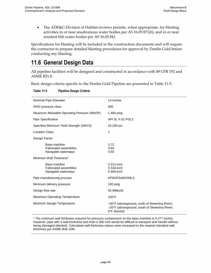
• The ADF&G Division of Habitat reviews permits, when appropriate, for blasting activities in or near anadromous water bodies per AS 16.05.871(b), and in or near resident fish water bodies per AS 16.05.841.
Specifications for blasting will be included in the construction documents and will require the contractor to prepare detailed blasting procedures for approval by Donlin Gold before conducting any blasting.
11.6 General Design Data
All pipeline facilities will be designed and constructed in accordance with 49 CFR 192 and ASME B31.8.
Basic design criteria specific to the Donlin Gold Pipeline are presented in Table 11-5.
Table 11-5 Pipeline Design Criteria
Nominal Pipe Diameter 14 inches
ANSI pressure class 600
Maximum Allowable Operating Pressure (MAOP) 1,480 psig
Pipe Specification API 5L X-52 PSL2
Specified Minimum Yield Strength (SMYS) 52,200 psi
Location Class 1
Design Factor
Base mainline Fabricated assemblies Navigable waterways
0.72 0.60 0.50
Minimum Wall Thickness1
Base mainline Fabricated assemblies
Navigable waterways
0.312-inch 0.344-inch
0.406-inch
Pipe manufacturing process HFW/DSAW/SMLS
Minimum delivery pressure 100 psig
Design flow rate 55 MMscfd
Maximum Operating Temperature 100F
Minimum Design Temperature –50F (aboveground, north of Skwentna River)
–20F (aboveground, south of Skwentna River)
0F (buried)
1 The minimum wall thickness required for pressure containment on the base mainline is 0.277 inches. However, pipe with a wall thickness less than 0.300 inch would be difficult to transport and handle without being damaged (dented). Calculated wall thickness values were increased to the nearest standard wall thickness per ASME B36.10M.
Donlin Pipeline, ADL 231908 Commissioner's Analysis and Proposed Decision
Attachment B Draft Design Basis
page 64

11.7 Pipeline Materials
11.7.1 Line Pipe
Line pipe will be API 5L X52 PSL2. The mainline pipe purchase specifications will include requirements for:
• Process of manufacture
• Chemical properties
• Mechanical properties (including longitudinal stress-strain behavior)
• Dimensions, weights, lengths, and end finishes
• Inspection and testing
• Marking
• Coating and protection
• Documents
• Pipe loading and transport
In addition to the material test reports required from the manufacturer for the mainline pipe, a certification of compliance with test results is required from the manufacturer for project acceptance of the mainline pipe.
The project approach to fracture control will consider crack initiation and propagation in the parent metal, seam welds, girth welds, and crack arrest. To control fracture initiation in the parent metal, it is necessary to ensure the material has sufficient toughness for failure to be dominated by plastic collapse. To prevent brittle fracture, the pipe must have a ductile to brittle transition temperature less than the specified minimum operating temperature.
It is not typically necessary to require the seam weld toughness to match that of the parent metal. Consistent with general industry practice for gas transmission pipelines, pipe sections will be laid with the seam welds offset so a crack initiating in the seam weld will only propagate for one pipe length. However, some level of toughness is required in the seam weld to give resistance to crack initiation, and this is set equivalent to the level required for flow stress dependent behavior in the parent pipe.
The most widely used predictive method for ductile fracture propagation and arrest is the Battelle “two curve” approach, where the crack tip driving force at arrest is considered and then a relationship is obtained between the arrest stress, the crack velocity, the pipeline dimensions, and material properties. This curve defines the driving force required to cause the crack to propagate; the driving force available is derived from modeling the decompression behavior of the escaping gas. Although the probability of ductile fracture propagation is low, the fracture length is further limited through a material specification of required minimum material toughness.
Donlin Pipeline, ADL 231908 Commissioner's Analysis and Proposed Decision
Attachment B Draft Design Basis
page 65

11.7.2 Valves
All pipeline valves will be ANSI Class 600, full-port ball valves with a maximum pressure rating of 1,480 psig. Valves will conform to API 6D, Specification for Pipeline Valves. It is anticipated most MLV will be installed below grade.
MLV may be actuated at the BPL tie-in, compressor station, and at the pipeline terminus. Other locations may be used for automatic line break valves in accordance with 49 CFR 192.935. All other MLV will be manually operated.
At locations where a remote telemetry unit (RTU) is chosen to operate a line break valve, a fiber optic amplifier can be added to lessen the cost of the fiber optic system. Sudden change in status of the pipeline equipment such as starting and stopping the large units operated at the Donlin Mine should be telemetered to the pipeline leak detection so a line break valve does not prematurely operate.
Valves nominal pipe size (NPS) 4 and smaller will be equipped with lever-type operators. Valves larger than NPS 4 will be equipped with manual reduction gear operators. All valves will have a reasonable gear ratio for manual operation.
All buried valves will have weld-end by weld-end connections. All aboveground valves which will experience continuous pressure during normal operations will have weld-end connections on the pressure side and flanged-end connections on the normally unpressurized side.
11.7.3 Flanges and Fittings
All pipeline flanges and fittings on the Donlin Gold Pipeline will be ANSI Class 600 with a maximum pressure rating of 1,480 psig. Flanges and fittings will conform with ASME B16.5, Pipe Flanges and Flanged Fittings NPS ½ Through NPS 24; or ASME B16.9, Factory-Made Wrought Buttwelding Fittings.
11.8 Pipeline Appurtenances
11.8.1 Overpressure Protection
A pipeline overpressure protection system will be designed and installed in accordance with 49 CFR 192, which states in §192.195:
(a) General requirements. Except as provided in §192.197, each pipeline that is connected to a gas source so that the maximum allowable operating pressure could be exceeded as the result of pressure control failure or of some other type of failure, must have pressure relieving or pressure limiting devices that meet the requirements of §§192.199 and 192.201.
(b) Additional requirements for distribution systems. Each distribution system that is supplied from a source of gas that is at a higher pressure than the maximum allowable operating pressure for the system must—
(1) Have pressure regulation devices capable of meeting the pressure, load, and other service conditions that will be experienced in normal operation of the system, and that could be activated in the event of failure of some portion of the system; and
Donlin Pipeline, ADL 231908 Commissioner's Analysis and Proposed Decision
Attachment B Draft Design Basis
page 66

(2) Be designed so as to prevent accidental overpressuring.
An overpressure protection system will be installed upstream of the pipeline inlet/downstream of the compressors and will consist of gas control monitoring with redundant pressure regulation.
Overpressure protection upstream of the compressor station will be provided by the gas supplier. The pipeline has the same ANSI flange rating as the existing supply pipeline.
11.8.2 Mainline Block Valves
MLV will be spaced in accordance with 49 CFR 192.179, Transmission Line Valves. The spacing will not exceed 20 miles. The spacing may be reduced to allow a valve to be installed in a more accessible location, with continuous accessibility being the primary consideration.
All buried valves will be equipped with an extension to allow closure in conditions where significant snow cover may exist.
All MLV assemblies will include bypass and blowdown piping and valving to allow pressure equalization across the mainline block valve and evacuation of the mainline on either side.
• The blowdown piping will be approximately one-third the diameter of the MLV.
• Each blowdown valve will have a vertical stack topped by a blind flange or removable cap; if caps are provided, they will be manufactured to accept a padlock.
• Noise reduction devices may be installed on the blowdown stacks, if deemed necessary.
Valve sites will be fenced with a minimum 8-foot-high chain link fence around the perimeter of a graded site. All MLV locations will require a gravel pad approximately 25 feet by 25 feet. Each site will be equipped with a helipad for maintenance and emergency access.
Valves will be pressure-tested by the supplier in accordance with the valve specification issued with the procurement order. Valve assemblies will be pressure-tested as a whole. Valves will not be pressure-tested in line with the pipeline, unless dictated by access issues and season of installation.
11.8.3 Launchers and Receivers
Launchers and receivers will be designed in accordance with ASME B31.8, except for closures, which will be designed in accordance with Section VIII of the ASME Boiler and Pressure Vessel Code. Barrels will be designed to accommodate a variety of In-line inspection (ILI) tool trains—multiple tools combined together to efficiently perform multiple types of inspections in a single run. Barrel design will consider the maximum tool length anticipated.
All launchers and receivers will have double block and bleed capabilities (i.e., two consecutive block valves with a bleed ring or pipe pup with bleed valve in between) to provide positive isolation from the pipeline downstream of the launcher and upstream of the receiver.
Donlin Pipeline, ADL 231908 Commissioner's Analysis and Proposed Decision
Attachment B Draft Design Basis
page 67

All branches greater than 25% of the main run diameter will be barred. Closures will be configured for horizontal operation.
Spacing of launchers and receivers will take into consideration battery life and data storage limitations of the ILI tools expected to be deployed. In addition, the potential for liquids within the line will be evaluated and considered in the determination of acceptable spacing.
Launcher and receiver assemblies may be hydrostatically tested separately from the pipeline.
11.8.4 Beluga Pipeline Tie-in
The tie-in to the BPL is planned for an NPS 8 hot tap in accordance with 49 CFR 192, ASME B31.8, and ENSTAR specifications and procedures. The hot tap is planned for the 12:00 position on the BPL inside a concrete valve vault. The top of the vault is planned to be above the surface of the ground, and the Donlin Gold piping will exit through the top or the side of the vault and connect to valving and associated metering equipment, before connecting to the main pipeline.
11.9 Bending
11.9.1 Field Bends
Requirements for field bending of line pipe are given in 49 CFR 192 and ASME B31.8.
49 CFR 192.313, Bends and Elbows, states:
(a) Each field bend in steel pipe, other than a wrinkle bend made in accordance with §192.315, must comply with the following:
(1) A bend must not impair the serviceability of the pipe.
(2) Each bend must have a smooth contour and be free from buckling, cracks, or any other mechanical damage.
(3) On pipe containing a longitudinal weld, the longitudinal weld must be as near as practicable to the neutral axis of the bend unless:
(i) The bend is made with an internal bending mandrel; or
(ii) The pipe is 12 inches (305 millimeters) or less in outside diameter or has a diameter to wall thickness ratio less than 70.
ASME B31.8 Paragraph 841.23, Bends, Elbows, and Miters in Steel Pipelines and Mains, presents two methods for determining the maximum degree of bending on a field bend. The first is expressed as the maximum deflection in an arc length equal to the nominal outside diameter (2.7 degrees for 14-inch nominal diameter pipe), and the second is expressed as the minimum radius as a function of the nominal outside diameter (21D for 14-inch nominal diameter pipe).
The project design degree of bending as measured by deflection along the longitudinal axis on a field bend is 2.5 degrees within an arc length equal to the nominal outside diameter of the pipe. Maximum field bend angle is limited to 24 degrees.
Donlin Pipeline, ADL 231908 Commissioner's Analysis and Proposed Decision
Attachment B Draft Design Basis
page 68

Field bends will be used for general pipeline alignment as overbends, sagbends, and sidebends.
11.9.2 Induction Bends
Induction bends will be designed and fabricated according to ASME B16.49-2012, Factory-Made Wrought Steel, Buttwelding Induction Bends for Transportation and Distribution Systems. The minimum bend radius will be three pipeline diameters (3D) to accommodate passage of inline inspection tools.
The number of induction bends will be minimized due to higher fabrication, transportation, and installation costs.
Pipe wall thickness for induction bends will be specified to satisfy the steel pipe design formula in 49 CFR 192.105 after any thinning caused by creation of the bend.
11.9.3 HDD Bends
The nominal design radius of sag and side bends on HDD installations in feet will be 100 times the nominal diameter of the pipeline in inches (1200 times the nominal diameter in feet per ASCE Publication Pipeline Design for Installation by Horizontal Directional Drilling). For the proposed 14-inch diameter pipeline, the nominal design radius for bends will be 1,400 feet.
11.10 Welding
The line will be welded according to the requirements of API 1104, Welding of Pipelines and Related Facilities, and project-specific requirements. Specific welding procedures will be developed. All field welds will be inspected using ultrasonic, radiographic, or other approved methods.
11.11 Buoyancy Control
Pipe flotation calculations will determine buoyancy control requirements. The calculations will compare the buoyant force on the pipeline to the external forces required to keep the pipeline from floating. Elevated fluid specific gravities will be used in the calculations where appropriate to account for higher buoyant force generated in sediment-laden waters, or where warranted based on other considerations.
For wall thicknesses contemplated, the pipeline will be buoyant in high water table areas, at water crossings, and at directionally drilled crossings.
Depending on the overall length of the high water table areas being crossed and types of soils within these areas, buoyancy control may not be required. Where forces resisting flotation (pipe weight, overburden, soil strength) are 110% or more of the buoyant force (calculated using appropriate specific gravity), buoyancy control will not be required. Where the forces resisting flotation are less than 110% of the buoyant force, buoyancy control measures will be required.
Potential buoyancy control measures include increased pipe wall thickness, concrete coating, bolt-on weights, or saddlebag weights. Note at directionally drilled crossings, permanent buoyancy control is not required; if temporary buoyancy control is deemed
Donlin Pipeline, ADL 231908 Commissioner's Analysis and Proposed Decision
Attachment B Draft Design Basis
page 69

necessary for installation this will be accomplished by flooding the pipe or by placing a smaller diameter pipe, possibly flooded, inside the main pipe.
11.12 Crossings
11.12.1 Road Crossings
The pipeline will cross Pretty Creek Road near the compressor station. This crossing is classified as minor road crossings and will be crossed via an open cut method.
The minimum burial depth (see Section 11.4) will be verified based on calculations in accordance with API RP 1102, Steel Pipelines Crossing Railroads and Highways, and Borough requirements (if any). Burial depth may be increased if required based on the calculation results. The design vehicle will be conservatively based on American Association of State Highway and Transportation Officials (AASHTO) HS20-44 wheel loading (32,000 pound axle load).
11.12.2 Water Crossings
Pipeline crossings of watercourses, environmentally sensitive areas, large bodies of water, and wetlands areas will be in accordance with standard industry practice and all applicable local, State, and Federal laws and permit requirements.
Pipeline crossings of watercourses will be achieved by buried methods to the maximum extent possible. The method selected will depend on the season of crossing, terrain, and geotechnical and environmental conditions. Crossings will be installed via open-cut; where open-cut is not feasible installation will be via HDD, slick bore, or other microtunneling method. The pipe will be coated with abrasion-resistant overlay (ARO) at all HDD locations.
Erosion or degradation could be caused by breaching of stream banks during construction or future operations. Conventional, open-cut water crossings will be designed with a gradual approach of the ditch to the streambed from each side, with free-stress sagbends and overbends extending far enough into the banks to prevent exposure that might be caused by erosion or scour. Where necessary, bank protection should be provided by using geotextile matting, riprap armoring, or other appropriate methods. A schematic of a typical watercourse crossing is presented in Figure 11-2.
Donlin Pipeline, ADL 231908 Commissioner's Analysis and Proposed Decision
Attachment B Draft Design Basis
page 70
Figure 11-2 Schematic of a Typical Watercourse Crossing
11.12.3 Foreign Crossings
There are no known foreign crossings (crossings of facilities owned by others) of underground facilities on this project.
Donlin Pipeline, ADL 231908 Commissioner's Analysis and Proposed Decision
Attachment B Draft Design Basis
page 71

12 Pipe Stress Analysis
12.1 Introduction
This section outlines the stress analysis design criteria, and the design procedures established to ensure the fundamental safety and structural integrity of the pipeline. Applicable regulations, codes, and criteria pertaining to stress analysis are presented. The types of loads, loading conditions, and combinations of loads are identified and discussed. The design criteria for acceptable levels of stress and strain in the pipe are established for all identified loading conditions. The appropriate methods and procedures of analysis to be used in the final design are subsequently defined.
12.2 Classification of Loading Conditions
The loadings are classified as to their effect on stress and strain as either primary or secondary. Definitions of primary and secondary stress vary between codes and are not specifically stated in 49 CFR 192. The project definitions are as outlined below:
• A primary load is a load which is not self-limiting and cannot be relieved by yielding or distortion. Primary loads on a pipeline include internal pressure and dead load of the pipe and its contents.
• A secondary load is a load which is self-limiting and can be relieved by yielding or distortion. Such a load is caused by movement of supports, restraint of adjacent parts, or self-constraint of the structure. Secondary loads on a buried pipeline include the effects of temperature changes, the effects of earthquake and the effects of movement of the surrounding soil media caused by displacement at bends and differential settlement, liquefaction or frost heave.
The conditions for which the pipe design is analyzed are classified as follows:
• Transportation loads are those imposed during handling, loading, stacking and shipping of the pipe.
• Construction loads are loads resulting from construction traffic and handling.
• Pre-operation loads include settlement that may occur after installation, and during the hydrostatic testing.
• Design operating loads are the sustained loads imposed by normal operations of the pipeline and the maximum expected loads resulting from movement at bends, and settlement. Wind and snow loads are included for aboveground pipe segments.
• Design maximum loads (contingency loads) include design operating loads combined with occasional loads, such as loads from extreme conditions with a low probability of occurrence during the lifetime of the pipeline, such as the Maximum Credible Earthquake.
Donlin Pipeline, ADL 231908 Commissioner's Analysis and Proposed Decision
Attachment B Draft Design Basis
page 72

12.3 Design Loads
The design loads to be considered for the pipeline analysis and design are included in the following sections.
12.3.1 Internal Pressure
Internal pressure is a primary load which induces primary circumferential tensile stress and strain in the pipe wall by expanding the pipe radially. If the pipe is unrestrained, pressure also induces axial tensile stress by expanding the pipe longitudinally. Once buried, the pipeline is restrained and axial tensile stress develops as a result of Poisson's effect. Internal pressure governs the required pipe wall thickness in accordance with the requirements of 49 CFR 192.
For a given operating pressure, the wall thickness required to meet this limitation is calculated using Barlow's formula in the following form:
t = PD/[2S (F × E × T)]
where:
t is the pipe wall thickness (inches)
P is the design operating pressure (psig)
D is the pipe outside diameter (inches)
S is the specified minimum yield (psi)
F is the design factor
E is the longitudinal joint factor
T is the temperature derating factor
The factor F is determined by Class Location in accordance with 49 CFR 192.111.
The factors E and T are determined in accordance with 49 CFR 192.113 and 192.115, respectively, and are equal to 1.0.
The component of hoop stress resulting from internal pressure is determined using Barlow's formula as presented below:
σh = PD/2t
where:
σh is the hoop stress (psi)
P is the internal pressure (psig)
D is the pipe outside diameter (inches)
t is the pipe wall thickness (inches)
Donlin Pipeline, ADL 231908 Commissioner's Analysis and Proposed Decision
Attachment B Draft Design Basis
page 73

In the unrestrained condition (e.g., aboveground piping), longitudinal stresses are defined by the product of the internal pressure and the cross-sectional flow area of the pipe divided by the area of the steel:
σL = APP/As
where:
σL is the longitudinal stress (psi)
AP is the cross-sectional flow area of the pipe, (in2)
P is the internal pressure (psig)
As is the cross-sectional area of pipe steel (in2)
In the restrained condition (e.g., buried piping), longitudinal stresses are defined by the product of Poisson's ratio and the hoop stress:
σL = PD/2t
where:
is Poisson's ratio, 0.3
12.3.2 Dead Load
Dead loads include the weight of the pipe, its contents, and externally applied loads such as corrosion or abrasion coatings, concrete coating, or concrete weights.
12.3.3 Temperature Differential
The buried pipeline will be partially or fully restrained from expansion or contraction by the backfill and surrounding soil medium. Any change in temperature of the pipe steel after installation will induce secondary longitudinal stress. A rise or fall in the pipeline steel temperature during operation or testing will induce compressive or tensile membrane stress respectively. The elastic analysis for buried pipe considers full restraint at maximum positive and negative temperature differential.
Longitudinal membrane stresses caused as a result of the temperature differential in the fully restrained pipeline are defined by:
σL = E(T–Ti)
where:
σL is the longitudinal stress (psi)
E is the modulus of elasticity (psi)
is the coefficient of thermal expansion (in/in/°F)
T is the temperature in question (°F)
Ti is the installation temperature (°F)
Donlin Pipeline, ADL 231908 Commissioner's Analysis and Proposed Decision
Attachment B Draft Design Basis
page 74

In unrestrained aboveground segments of the pipeline, the thermal expansion and contraction produces longitudinal force and induces secondary longitudinal bending stress at bends, offsets, and supports. The design temperature differentials will be input into an elastic analysis in combination with other applicable loads.
12.3.4 Overburden and Vehicular Loads
The weight of the backfilled soil over the pipe is a primary load, bearing on the upper surface of the pipe and inducing a circumferential bending stress in the pipe wall. In areas where settlement may occur or in areas where the ditch bottom profile will not provide uniform support to the pipe, the overburden load may induce longitudinal stresses and strains in the pipe prior to operations.
The weight of the backfill above the buried pipe will deform the pipe and induce a circumferential bending stress in the pipe. The overburden load may be conservatively taken as equal to the weight of the soil prism above the pipe:
WO = HD
where:
WO is the overburden load (plf)
is the backfill unit weight (pcf)
D is the pipe outside diameter (ft)
H is the height of fill above the top of the pipe (ft)
Additional load will be transmitted to the pipe at road crossings from vehicular traffic. Applicable wheel loads which have been factored for impact will be applied as a surcharge to the pipe in addition to the overburden. Determination of the total load W for use in equations will be made as follows:
W = WO + WS
where:
WO is the appropriate overburden load
WS is the surcharge load due to the applied wheel loading
The deformation and circumferential stress response of the pipe to the combined effects of the overburden and design vehicular loads are functions of the backfill load, the properties of the pipe, and the properties of the soil around the pipe. The resulting deformation and circumferential stress will be calculated considering the effect of the load transmitted through the subsurface to the pipe using soil mechanical properties appropriate for the specific site, and the pipe mechanical properties. Analysis may be concluded though accepted manual calculations (e.g., Spangler equations), or by appropriate finite element analysis. In certain site-specific locations where detailed soils data are available, the overburden load may be calculated with consideration of the arching effect.
Donlin Pipeline, ADL 231908 Commissioner's Analysis and Proposed Decision
Attachment B Draft Design Basis
page 75

In cases where the construction specifications allow non-uniform support of the pipe or in site-specific locations where actual support conditions are determined, the residual longitudinal strain from overburden loading will be included in determining the total longitudinal strain for comparison with the criteria allowables. The residual strain will be calculated as the strain resulting from the bending moment in the unpressurized pipe caused by the weight of the overburden extending over a span equal to the allowable unsupported length of pipe.
12.3.5 Buoyancy
The effect of buoyant uplift on the buried pipe will also be considered as a dead load. Buoyant uplift can occur in areas where the pipeline is partially or fully submerged in water or saturated soil-water medium. Seismic activity may also cause a buoyant effect in certain liquefiable soils.
12.3.6 Snow, Ice, and Wind Loads
The aboveground segments of the pipeline will be subjected to loading from snow, ice, and wind. These produce longitudinal bending stresses, which will be considered primary loads.
12.3.7 Seismic Loads
Body waves, including compression waves and shear waves, propagate radially from the source of earthquake energy release (hypocenter) into the surrounding rock and soil medium. Compression waves cause axial compressive and tensile strains in the ground in a radial direction away from the hypocenter. Shear waves cause shear strains in the ground perpendicular to these radial lines. When the compression waves and shear waves are reflected by interaction with the ground surface, surface waves (Love waves and Rayleigh waves) are generated. Except at very large distances from the epicenter, the magnitude of surface waves is much less than body waves.
In the buried pipeline, the passage of these ground waves will incur longitudinal and bending strains as it conforms to the associated ground strains. In most cases, these strains are relatively small, and welded pipelines in good condition typically do not incur damage. Propagating seismic waves also give rise to hoop membrane strains and shearing strains in buried pipelines, but these strains are even smaller and may be neglected.
Resulting membrane and bending stresses are considered secondary.
The maximum axial strain, εg, induced in a buried pipeline by seismic wave propagation can be approximated using the formula presented in American Lifelines Alliance (ALA), Guidelines for Design of Buried Steel Pipelines (ALA 2001):
g = Vg/CS
where:
g is the maximum longitudinal membrane strain (in/in)
is the ground strain coefficient:
= 1.0 for compression and Rayleigh waves, and
Donlin Pipeline, ADL 231908 Commissioner's Analysis and Proposed Decision
Attachment B Draft Design Basis
page 76

= 2.0 for shear waves;
CS is the propagation velocity of the seismic wave (in/sec)
Vg is the maximum horizontal ground velocity (in/sec)
The apparent propagation velocity is the inverse of the “slowness,” a term used in seismology. The slowness is a function of the source-to-site geometry and the wave propagation velocity along the entire path of propagation typically ranging from 6,560 to 11,480 fps (2.0 to 3.5 km/sec). Hence, an apparent propagation velocity of 6,560 fps (2 km/sec) can generally be taken as a lower bound estimate that will provide a maximum estimate of ground strain. The direction of wave propagation is typically assumed to be the longitudinal direction of the pipeline, since this assumption results in the largest axial strain effect applied to the buried pipeline, although the direction may be chosen as the actual seismic propagation direction if site-specific or source specific information is available.
If there is no slippage of the pipeline relative to the surrounding soil, then the maximum axial strain in the pipeline is equal to the maximum ground strain, evaluated as:
g = Vmax/CS
If slippage occurs, then pipeline longitudinal strains will be less than the ground strain, i.e., the maximum axial strain in the pipe is:
g = f Vmax/CS
where:
f Reduction factor (f ≤ 1.0) to account for the slippage effect. Present analysis uses a value of 1.0 for “f” which can be seen to produce a conservative estimate of the induced axial strain. Lower values of “f” are permitted if specific conditions justify their use. Appropriate justification will be provided for any lower value used in final design. In no case will “f” be less than 0.5.
For the aboveground sections of pipeline and its support system, the reference earthquake ground motions are in the horizontal plane, and the effects of vertical ground motion will be considered as being equal to two-thirds of the horizontal. These ground motions will be applied to produce the maximum effects on the pipeline and its supports.
At fault crossings the pipeline will be designed to accommodate the design ground displacements.
12.4 Load Combinations
Design loads occurring simultaneously will be combined and the resulting stresses and strains will be limited in accordance with the design criteria specified in this section. Loading combinations to be analyzed are outlined in Table 12-1, and Table 12-2.
Donlin Pipeline, ADL 231908 Commissioner's Analysis and Proposed Decision
Attachment B Draft Design Basis
page 77

Table 12-1 Load Combinations for Buried Pipe
LOADS
COMBINATIONS
1 2 3 4 5 6 7 8 9
Design Pressure X X X X X X X
Test Pressure X
Zero Gage Pressure X
Operating Temperature Differential X X X X X
Test Temperature Differential X
Dead Load - Operating X X X X X
Dead Load - Test X
Seismic Ground Motion X X X
Overburden X X X
Traffic Loads X X
Buoyancy X X
Table 12-2 Load Combinations for Aboveground Pipe
LOADS
COMBINATIONS
1 2 3 4 5 6
Design Pressure X X X X
Test Pressure X
Operating Temperature Differential X X X
Test Temperature Differential X
Dead Load - Operating X X X
Dead Load - Test X
Seismic Ground Displacements X
Wind X
Snow/Ice X
Donlin Pipeline, ADL 231908 Commissioner's Analysis and Proposed Decision
Attachment B Draft Design Basis
page 78

12.4.1 Maximum Allowable Stresses and Strains
12.4.1.1 Maximum Allowable Stress Levels
The maximum allowable stress levels are presented in Table 12-3 and Table 12-4.
Table 12-3 Allowable Stresses in Buried Pipe
DESCRIPTION ALLOWABLE LOAD
COMBINATION (Table 12-1)
Hoop Stress DF SMYS 1
Circumferential Bending Stress from design or zero pressure, overburden, and traffic loads
0.90 SMYS (ASME B31.8, 833.9)
2 3
Longitudinal Stress from design gage pressure, temperature differential, and other operating loads
0.90 SMYS (ASME B31.8, 833.3)
4 5
Effective Stress from design or zero gage pressure, temperature differential, and other operating loads
0.90 SMYS (ASME B31.8, 833.4)
4 5
Effective Stress from test pressure, test temperature differential, and test dead load
1.00 SMYS (ASME B31.8, 833.4)
6
Effective Stress from design pressure, temperature differential, other operating loads, and MCE
1.15 SMYS (Project Design)
7 8 9
Table 12-4 Allowable Stresses Aboveground Pipe
DESCRIPTION ALLOWABLE LOAD
COMBINATION (Table 12-2)
Hoop Stress DF SMYS 1
Longitudinal Stress from design pressure, operating dead load, and occasional loads (wind, snow, and ice loads)
0.75 SMYS (ASME B31.8, 833.6)
2
Expansion stress from temperature differential Varies (ASME B31.8, 833.8)
3
Effective Stress from design pressure, temperature differential, and operating dead load
0.90 SMYS (ASME B31.8, 833.4)
4
Effective Stress from design pressure, temperature differential, operating dead load, and MCE
1.10 SMYS (Project Criteria)
5
Effective Stress from test pressure, test temperature differential, and test dead load
1.00 SMYS (ASME B31.8, 833.4)
6
Donlin Pipeline, ADL 231908 Commissioner's Analysis and Proposed Decision
Attachment B Draft Design Basis
page 79

12.4.1.2 Allowable Curvature
The allowable curvature is based on the curvature computed from the allowable longitudinal compressive strain (compressive strain demand limit) or the allowable longitudinal tensile strain (tensile strain demand limit), whichever results in a smaller value. The allowable curvature will consider deductions for the membrane strains that may arise concurrently with the bending.
12.4.2 Maximum Allowable Stress Levels for Transportation and Stacking
• Circumferential bending stress during rail or truck transport (API RP-5L1): 0.30 Ultimate Tensile Strength (UTS).
• Circumferential bending stress during marine transport (API RP-5L5): SMYS/(1+g) (where g is taken as 0.4 unless recommended higher by shipper).
• Circumferential bending stress during yard stacking: 0.50 SMYS.
12.4.3 Maximum Allowable Pipe Ovalling
The maximum allowable decrease in pipe diameter resulting from overburden and wheel
loading is 5% of the pipe diameter (x <0.05D).
12.4.4 Elastic Stability
Pipeline sections subjected to axial compression loadings will be checked for column buckling in accordance with the Euler formula. The maximum unsupported span will be limited to 80 percent of the calculated critical buckling span considering appropriate boundary conditions.
12.5 Strain Design Criteria
For the evaluation of the effect of earth movement (e.g. thaw settlement), inelastic large displacement analysis methods will be employed to determine the expected site-specific strain demand in the pipelines. If the calculated strain demand is greater than the yield strain (0.5 percent strain), the capacity of the pipe material to safely resist the strain demand must be further evaluated.
The strain capacity will be assessed through procedures to evaluate the tensile and compressive strain capacities (respectively) at the limit states of the pipe material (see Section 12.5.1), and then reduced by values to increase confidence in the allowable limit to the strain demand (see Section 12.5.2). The strain demand will compared to the strain demand limit to ensure it does not exceed the allowable at any place along the alignment. All calculations will account for variables outlined in B31.8 – pertinent sections are cited below:
ASME B31.8 Section 833.5, Design for Stress Greater Than Yield states:
The limits in paras. 833.3 and 833.4 [allowable stress criteria] may be exceeded where due consideration is given to the ductility and strain capacity of seam weld, girth weld, and pipe body materials; and to the avoidance of buckles, swelling, or coating damage.
Donlin Pipeline, ADL 231908 Commissioner's Analysis and Proposed Decision
Attachment B Draft Design Basis
page 80

The maximum permitted strain is limited to 2 percent.
12.5.1 Preliminary Strain Capacity
Preliminary compressive and tensile strain capacities were calculated using predictive equations developed by the Pipeline Research Council International, Inc. (PRCI) and Center for Reliable Energy Systems (CRES) for the U.S. Department of Transportation, Pipeline and Hazardous Materials Safety Administration (PHMSA). Compressive strain capacity equations are given in Realistic Strain Capacity Models for Pipeline Construction and Maintenance (CRES 2013); and tensile strain capacity equations are given in Second Generation Models for Strain-Based Design (PRCI 2011). Results of preliminary calculations for the longitudinal compressive and tensile strain capacities are presented in Table 12-5.
Table 12-5 Preliminary Longitudinal Strain Capacities
Wall Thickness Longitudinal Compressive
Strain Capacity Longitudinal Tensile Strain
Capacity
0.312-inch 1.63% 1.17%
0.344-inch 1.84% 1.28%
0.406-inch 2.04% 1.54%
0.500-inch 2.94% 2.07%
These preliminary values will be verified, and modified as required, by results of testing of the pipe material specified for use on the Donlin Gold pipeline, and designated for use in high strain areas.
12.5.2 Strain Demand Limits
The compressive strain allowable limit (termed by PHMSA as the strain demand limit) will be set at 0.8 times the compressive strain capacity. The tensile strain allowable limit (likewise termed the tensile strain demand limit) will be set at 0.6 times the tensile strain capacity. Longitudinal compressive and tensile strain demand limits, based on the preliminary evaluation of the strain capacity in Section 12.5.1, are presented in Table 12-6.
Table 12-6 Preliminary Longitudinal Strain Demand Limits
Wall Thickness Longitudinal Compressive
Strain Demand Limit Longitudinal Tensile Strain
Limit
0.312-inch 1.31% 0.70%
0.344-inch 1.47% 0.77%
0.406-inch 1.80% 0.93%
0.500-inch 2.36% 1.24%
Donlin Pipeline, ADL 231908 Commissioner's Analysis and Proposed Decision
Attachment B Draft Design Basis
page 81

12.6 Nonlinear Analyses for Buried Pipe
12.6.1 General
Nonlinear analyses will be performed on the buried pipe to consider the effects of secondary stress and strain produced by geotechnical conditions.
The purpose of the nonlinear analysis is to provide a more realistic representation of structural behavior to determine either load-deformation or load-strain relations for the structure and/or its individual elements. Nonlinear analyses are based upon an idealization of actual material properties. The analyses are complex mathematical models requiring the use of computer programs. The steel stress-strain relationship (i.e., stress-strain curve) is a basic input required for completing these computations.
Studies will be conducted to investigate pipe stress and strain under anticipated design loading conditions and soil response. The objective of the studies will be to determine the limits of pipe displacement and deformation allowed by the criteria limits. Via the analysis, pipe curvature changes occurring under design loadings can be related to the allowable levels.
12.6.2 Input Modeling for Pipe Stress Analysis
The accuracy of the results from a pipe stress computer analysis is dependent upon the techniques used in preparing the program input. A suitable procedure for input modeling is discussed below.
Four categories of input to the program are required:
• Geometrical Configuration
• Material Properties of the Pipe
• Soil Resistance Properties
• Loading Conditions
The geometrical configuration is idealized by representing a section of pipe which is divided into a number of segments.
Pipe material properties will be input by specifying a series of data points on the stress-strain curves in the hoop, longitudinal-compressive, and longitudinal-tensile directions, a value for Poisson's ratio, and the-coefficient of thermal expansion. The pipe diameter and wall thickness will also be specified.
Soil restraint is represented as a series of discrete spring functions acting along the discrete segments within the analysis model. For example, uplift soil restraining functions may be represented by a multi-linear force-displacement function.
Loadings include gravity (self-weight, overburden, etc.), internal pressure, temperature differential, and imposed displacements such as those caused by thaw settlement of the supporting soils. The computer program combines the applied loads in a particular sequence as specified by the user. Each load step is considered a continuation from the
Donlin Pipeline, ADL 231908 Commissioner's Analysis and Proposed Decision
Attachment B Draft Design Basis
page 82

previous load step; the stresses, strains, loads, and displacements at each element will be given at the end of each load step.
12.7 Differential Ground Movement
At some locations along the pipeline, geotechnical conditions may exist which could potentially cause displacement of the soil around the pipe, such as displacement of the soil due to thaw settlement.
At any location where differential soil displacement may occur, the soil movement will have the effect of inducing a loading action on the pipe, the magnitude of these induced forces being a function of the amount of movement, and the soil properties. Design cases of soil displacement will be analyzed using an appropriate nonlinear procedure as discussed in Section 12.5.
In the nonlinear analysis, the soil movement is represented as a displacement of the soil springs. Both transverse and axial movements may be represented. The analysis will follow the two-stage procedure outlined below:
(1) Soil load-displacement characteristics for the displacement of the pipeline in relation to the soil will be determined.
(2) Pipeline response will be calculated incorporating the following behavior phenomena:
• Soil behavior
• Pipe material behavior
• Pipe operating conditions—internal pipe pressure and differential temperature
12.7.1 Route Characterization for Differential Displacement Studies
A buried pipeline is essentially continuously supported by the ditch bottom. However, certain geotechnical conditions could cause vertical movement of the supporting soil which then must be evaluated for potential distress conditions that could arise in the pipe.
Ground movement studies may be performed at specific locations, such as thaw unstable regions. The majority of the pipeline, however, will traverse areas where accurate information about localized ground movements cannot be specifically determined. The general approach method for non-site-specific locations is outlined below:
• Classify the design cases into Soil Groups, based upon combinations of end conditions, soil types outside the zone of settlement and soil types within the zone of settlement.
• Determine the soil load displacement functions for each selected Soil Group for a range of cover depths and a range of pipe operating conditions (e.g., temperature differential).
• Develop the input models for a computer analysis for a range of spans for the selected Soil Groups, depths of cover, and pipe operating conditions.
Donlin Pipeline, ADL 231908 Commissioner's Analysis and Proposed Decision
Attachment B Draft Design Basis
page 83

• Perform analyses for the range of potential ditch bottom movement for each combination of soil group, depth of cover, and pipe operating conditions. The allowed ditch bottom movement for each span is the ditch bottom movement at which the allowable pipe limits are reached.
• Determine the critical span at which the allowable ditch bottom movement will be at a minimum from the analyses sets. This will be the total allowable ditch bottom movement, independent of span, for a given soil group, depth of cover, and pipe operating condition.
From these analyses, design charts will be developed identifying the allowable movement for each soil group at each depth of cover and pipe operating condition. The values obtained from the analyses will then be mapped to the route soil conditions and pipe operating conditions along the pipeline alignment, identifying areas where mitigation is required.
12.7.2 Movement from Frost Heave and Thaw Settlement
The most significant source of differential pipe movement for the alignment may be by frost heave or thaw settlement:
• Frost heave is likely to occur in areas of frost-susceptible soils where natural factors and/or pipeline construction activity influence the shallow groundwater regime, promoting ice lens formation and subsequent upward heave of the pipe during winter. In addition to putting strain on the pipe, frost heave could potentially disrupt surface drainage patterns.
• Thaw settlement refers to the downward movement of the pipeline caused by thawing of ice-rich permafrost soils and associated loss of soil volume beneath the pipe. High stresses can result in the pipe if it becomes suspended between areas of thaw-stable ground. Thaw settlement can also cause ponding of surface water, leading to accelerated thawing and, possibly, more settlement.
Because the pipeline will be operating at/near ambient ground temperatures, there should be no significant driving force for frost bulb formation or thaw settlement beneath the pipe from the pipe operation. However, disturbance of the thermal regime due to construction activities may lead to frozen, ice-rich soils in some areas along the route.
12.8 Bend Analysis
As the pipeline traverses the route, changes in pipeline alignment, terrain, grade, and ditch conditions may require installation of field bends. These field bends will be made by means of bending machines. For practical purposes, and to prevent wrinkling or other damage to the pipeline, the pipe will be bent to a minimum radius of curvature of 24.5 feet (minimum radius of factory bends will be 3.5 feet) (see Section 11.9).
When a bent section of pipe is subjected to loading, such as hydrostatic test pressure, operating pressure, variations in temperature, seismic loading etc., straining of the pipe will occur and the pipe will tend to be displaced from its original position. This pipe displacement will be resisted by the stiffness of the pipe, the longitudinal restraint between the soil and pipe, and the transverse soil resistance.
Donlin Pipeline, ADL 231908 Commissioner's Analysis and Proposed Decision
Attachment B Draft Design Basis
page 84

The permissible amount of displacement and axial straining at a bend are checked by conducting analyses of bends using a pipe stress computer program. The allowable bend angles will be determined from these studies.
12.9 Aboveground Supports
Aboveground pipeline supports will be designed in compliance with AISC 360-05 Specification for Structural Steel Buildings and Commentary.
12.10 Minimum Free Stress Installation Radius
As the pipe is installed, it must conform to the trench, which results in stresses and strains within the pipe. It is desirable that the pipe remain elastic under these conditions. This can be accomplished by maintaining a minimum free stress installation radius. Since the elastic limit stress is approximately 75% of the yield stress for API 5LX materials, the minimum free stress installation radius should not generate bending stresses that exceed 0.75 SMYS.
The relationship of bending stress to curvature in a pipe is given by the formula:
𝜌 =𝐷 ∙ 𝐸
2 ∙ 𝜎𝑎
where:
D is the pipe diameter (inches)
E is the Modulus of Elasticity (30,000,000 psi)
a is the allowable stress (psi)
is the radius of curvature (inches)
Therefore, the minimum free stress installation radius for the Donlin Gold pipeline is 447 feet.
Donlin Pipeline, ADL 231908 Commissioner's Analysis and Proposed Decision
Attachment B Draft Design Basis
page 85

13 Pressure Testing
13.1 Hydrostatic Testing of High-Pressure Pipelines
All onshore pipelines to be operated at or above 30 percent SMYS will be pressure tested for eight continuous hours, in accordance with 49 CFR 192 and the project construction specification. The minimum test pressure will be maintained above 125 percent of the MAOP. The maximum test pressure should not exceed the equivalent hoop stress of 105 percent SMYS.
The maximum working pressure of test head assemblies during pressure testing will not produce a hoop stress in excess of 75 percent of SMYS of the test head pipe. Ancillary piping such as fill lines must not be operated at pressures that produce hoop stresses in excess of 50 percent of SMYS in the ancillary piping.
Hydrostatic test segment lengths, break points, and test water source locations will be outlined in the project-specific pressure test plan (Pressure Test Plan) to be developed during the final design phase of the project. Test medium fluid may be transferred from segment to segment as required. Procedures will be designed to ensure compliance with 49 CFR 192 and any environmental or regulatory approvals or permits.
Components tested independently of the mainline will be hydrostatically tested in accordance with 49 CFR 192 and ASME B31.8 and subsequently tied in to the completed pipeline.
Only tests meeting all regulatory and project criteria will be accepted.
13.2 Cleaning and Drying
The pipeline will be cleaned of debris, dirt, and weld slag through the use of in-line cleaning tools before hydrostatic testing. The pipeline will be dried to a dewpoint of -40°F after completion of a caliper tool survey by using a combination of compressors/dryers and dewatering in-line tools or by an alternate method approved by Donlin Gold.
13.3 Cold-weather Testing
All hydrostatic testing is currently planned for the summer timeframe; however, the final construction plan may require winter or shoulder-season testing if summer access is not feasible. Regardless of the season during which testing occurs, no freeze-depressing solutions such as methanol or glycol will be used.
13.4 Discharge of Hydrostatic Test Water
Once hydrostatic testing has been completed, test water will be discharged back to an approved location through a filtration device. Water used for pipeline test purposes will be tested before discharge, as required by project permits. Energy-dissipating devices and/or filter bags will be used to prevent scour, erosion, suspension of sediment, and damage to
Donlin Pipeline, ADL 231908 Commissioner's Analysis and Proposed Decision
Attachment B Draft Design Basis
page 86

vegetation. Discharge rates will be monitored and kept within a range appropriate to maintain the effectiveness of the energy-dissipating devices.
13.5 Testing with Air or Gas
Testing with air or gas in lieu of hydrostatic testing may be considered based on construction requirements for seasonality of a specific section, or because of large elevation changes in a single test segment. Any segments to be tested with air or gas will be outlined in the project-specific pressure test plan (Pressure Test Plan) to be developed during the final design phase of the project.
Pneumatic testing will be conducted in accordance with 49 CFR 192.
Donlin Pipeline, ADL 231908 Commissioner's Analysis and Proposed Decision
Attachment B Draft Design Basis
page 87

14 Compressor Station
14.1 Overview
The compressor station will have two main components: natural gas compression machinery with after-coolers to reduce gas temperature following the compression process, and electrical generation machinery. Additional equipment necessary to support the compression process include systems to prevent overpressure and to provide rate, temperature and pressure control, trouble alarms, emergency shutdown (ESD) systems, and fire and gas detection systems.
In general, the Compressor Station will be comprised of:
• Three (3) Compressor Modules
• Three Fin-Fan Aftercoolers
• Power Distribution Center (PDC) Module
• Two Microturbine Generators
• Fuel Gas Conditioning Module
• Produced Liquids Handling Module
• Shop/Warehouse Building
• Launcher and Receiver Skids
Facilities will be sited on the pad to comply with code-required occupancy separation, and provide access to equipment within the buildings or modules. Snow drifting, snow removal and emergency vehicle access will also be considered in the pad layout. A 20-foot buffer space will be maintained between the fence line and the outer wall of any building or module to provide vehicle access to the entire pad and to all sides of the facilities.
The site will have adequate drainage to prevent any flooding or standing water.
Appropriate quantity and location of light fixtures will illuminate all working areas of the yard. LED lighting will be considered to keep energy usage low.
14.1.1 Site Location and Description
The compressor station will be located approximately 30 miles (48 km) northwest of Anchorage, approximately 8 miles (13 km) northeast of Beluga, within the Susitna Flats State Game Refuge approximately 0.4 miles (0.6 km) north of the proposed tie-in to the BPL. A location map for the compressor station is presented as Figure 14-1.
The site is accessible by road, helicopter and, in winter, by snowmobile. Meteorological data for Beluga, the nearest location with published weather statistics, is presented in Table 14-1.
Donlin Pipeline, ADL 231908 Commissioner's Analysis and Proposed Decision
Attachment B Draft Design Basis
page 88
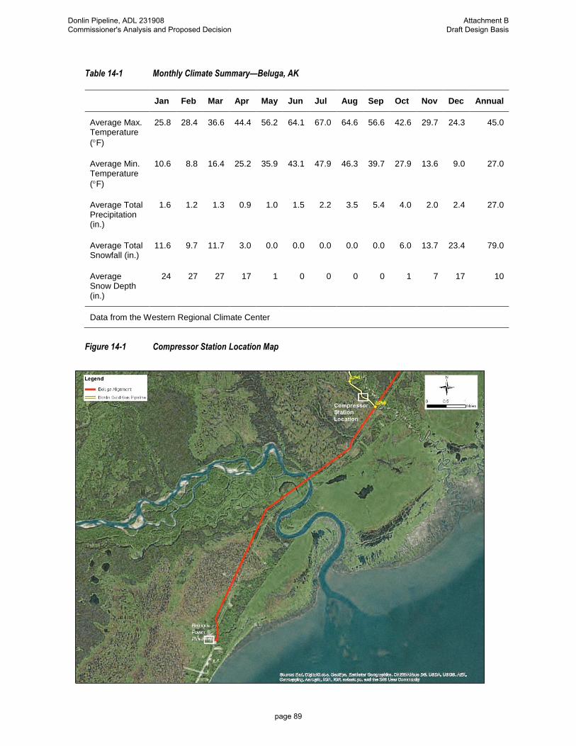
Table 14-1 Monthly Climate Summary—Beluga, AK
Jan Feb Mar Apr May Jun Jul Aug Sep Oct Nov Dec Annual
Average Max. Temperature
(F)
25.8 28.4 36.6 44.4 56.2 64.1 67.0 64.6 56.6 42.6 29.7 24.3 45.0
Average Min. Temperature
(F)
10.6 8.8 16.4 25.2 35.9 43.1 47.9 46.3 39.7 27.9 13.6 9.0 27.0
Average Total Precipitation (in.)
1.6 1.2 1.3 0.9 1.0 1.5 2.2 3.5 5.4 4.0 2.0 2.4 27.0
Average Total Snowfall (in.)
11.6 9.7 11.7 3.0 0.0 0.0 0.0 0.0 0.0 6.0 13.7 23.4 79.0
Average Snow Depth (in.)
24 27 27 17 1 0 0 0 0 1 7 17 10
Data from the Western Regional Climate Center
Figure 14-1 Compressor Station Location Map
Donlin Pipeline, ADL 231908 Commissioner's Analysis and Proposed Decision
Attachment B Draft Design Basis
page 89

A maintenance schedule has not been established. However, regular site visits will be necessary to perform maintenance activities such as refilling of the compressor lubrication reservoirs and changing of the coalescer filters.
No provisions will be made for human occupancy at the site. Site security requirements are presented in Section 18.5.
14.1.2 Geotechnical
The planned Donlin pipeline compressor station is located in a former material site near MP 0.4 of the Pretty Creek alignment. The Pretty Creek alignment extends east to west between the Pretty Creek drainage to the south and the Theodore River to the north. The origin of the pipeline (MP 0) is in the Cook Inlet lowlands, which is typically comprised of poorly drained marine and former beach deposits. As the Pretty Creek alignment extends westward toward the compressor station site, the terrain transitions from lowland to upland with a corresponding change in subsurface conditions that are more favorable support of the compressor station structures.
The Pretty Creek portion of the project was explored in 2013 with a series of boreholes completed with a geoprobe to depths ranging from 10.8 to 22 feet below the ground surface. Probes GP-001-PC through GP-005-PC were located in the lowlands from MP 0.5 to MP 3.5. These boreholes typically encountered 2 to 4 feet of organics overlying silt and sand. GP-006-PC was located in the terrain transition at about MP-3.8; it encountered a thin layer of organics overlying well graded sand. Probes GP-007-PC through GP-009-PC were located around MP 5 in the upland transition or in the abandoned floodplain of the Theodore River. These boreholes typically encountered less than 1 foot of organics and a few feet of silt or sand overlying well graded gravel. The gravel formation is a product of glacial outwash and is expected to be the dominant soil type underlying the planned Donlin compressor station site.
Groundwater was encountered at about 2 feet depth in GP-005-PC and GP-007-PC and at ±5 feet depth in the remainder of the Pretty Creek boreholes. Through the lowland, the Pretty Creek alignment parallels an existing gravel road that approximately follows the drainage divide between the Pretty Creek and Theodore River drainages but with little topographic relief between the road elevation and the drainages. With overburden removal and material excavation, the compressor station site may have groundwater at or near the ground surface.
Based on this summary of landforms and subsurface conditions, the compressor station site appears to be generally suitable for shallow foundations designed for moderate bearing pressures (3,000± pounds per square foot [psf] for minimum 42-inch burial depth). The site appears to have been used as a material borrow source, which suggests the possibility of site disturbance and/or burial of unsuitable soil or debris. Therefore site preparation in advance of foundation construction should consist of removal and off-site disposal of unsuitable soil or debris followed by compaction of disturbed native granular soils and levelling the building area with imported non-frost-susceptible granular fill. Site preparation should include construction of subdrains to assure groundwater levels will be at least 5 feet below the final site surface and below grade building spaces should generally be avoided. The Castle Mountain fault has been mapped near the location of the proposed compressor station location; however, project specific review of paleoseismic conditions for the Donlin Pipeline suggests the fault is inactive. Other than the potential for site conditions disturbed
Donlin Pipeline, ADL 231908 Commissioner's Analysis and Proposed Decision
Attachment B Draft Design Basis
page 90

by prior earthwork, possible buried debris, and probable shallow groundwater table, there are no known geohazards to be mitigated at the planned compressor station site. Detailed foundation design will be performed during final design activities.
14.1.3 System and Process Description
The compressor station will be unmanned, fully automated, and operated from the Pipeline Control Center (PCC).
The compressor station will be designed, operated, and maintained in accordance with national codes and standards. All equipment and components will use existing and proven technologies.
The compressors and their associated equipment and control systems will be designed and assembled by companies specializing in the packaging of such equipment. To accommodate environmental conditions, those units will be placed inside a building module. The design will make provisions for prefabrication of components, piping, and systems to the greatest extent practical to meet the objective of minimizing field construction activities and requirements.
The PDC and Power modules described below are classified as F-1 Light Industrial occupancy, and will have provision for heat and light to allow maintenance workers to service equipment for extended periods of time during winter or inclement weather. The other modules are classified as high-hazard or as unoccupied facilities, with minimum requirements for maintainers to enter. These require no heat, but do require electric lighting.
The compressor station will have the ability to deliver natural gas at different rates and pressures, depending on the fuel consumption demands of the mine.
The design will provide four methods of flow rate control:
• Zero compressors online: Based on a supply pressure of 720 psig, the pipeline will be able to deliver up to 36 MMscfd at the required delivery pressure of 100 psig.
• One compressor online: The system will be able to deliver up to a nominal 49.5 MMscfd.
• Two compressors online: The system will be able to deliver up to a nominal 60 MMscfd.
• The gas compressor(s) will be separable reciprocating type powered by natural gas engines. The engines will be complete with speed control and compressor torque control. Unit speed and torque control will provide the ability to adjust the speed of engines and compressors, correspondingly adjusting the flow rate of natural gas.
A preliminary compressor station layout is presented in Figure 14-2.
Donlin Pipeline, ADL 231908 Commissioner's Analysis and Proposed Decision
Attachment B Draft Design Basis
page 91

Figure 14-2 Preliminary Compressor Station Layout
Donlin Pipeline, ADL 231908 Commissioner's Analysis and Proposed Decision
Attachment B Draft Design Basis
page 92

Under normal operations, the gas will enter the station, directly to the compressor modules. The gas will then enter a suction scrubber to capture any free liquids. Those liquids will be reinjected into the pipeline for handling at the terminus. The gas will then enter the compressors and flow to filter coalescers for the removal of any lubrication oil carried over from the compressor cylinders. From there, the gas will be processed through an air-cooled heat exchanger (fin-fan) to reduce the gas temperature to within 20 degrees of ambient, but
not less than 40F. The gas will then enter the pipeline and be transported approximately 315 miles (507 km) to the mine site.
The fin-fan coolers will have automated valves on the inlet nozzle. If a cooler is in standby mode, the inlet valve will be closed. Opening the inlet valve and energizing the fan motors will place the cooler into service.
14.1.4 In-line Inspection and Maintenance Operations
The compressor station will have a receiver assembly at the inlet to the station and a launcher assembly at the outlet of the station. These assemblies will be vendor-supplied skids. See Section 11.8.3 for mechanical piping requirements.
Any liquids collected during the tool run will be captured in a gas/liquid separator located at the inlet to the compressor station. Those liquids will be pumped to the discharge side of the compressor station and transit the pipeline to the terminus, where they will be collected in another separator for proper handling and disposal. Based on historical data provided by ENSTAR, the Donlin Gold pipeline can expect to accumulate 20 gallons of liquid per year.
14.1.5 Pressure and Temperature Limitations
Based on information received from ENSTAR, the BPL has an MAOP of 1,031 psig. The Donlin Gold pipeline will have an MAOP of 1,480 psig. Therefore, it is not possible for the Donlin Gold pipeline to experience an overpressure event originating from the natural gas supplier.
It will be possible for the compressors to generate discharge pressures in excess of the MAOP of the Donlin Gold pipeline. Therefore, the compressor station and pipeline automation systems will provide multiple levels of overpressure protection.
The compressor station will also have ESD capabilities, including ESD valves that will isolate the station from the pipeline. Flow of natural gas will continue through the pipeline at a rate of approximately 36 MMscfd (1.0 million Nm3pd), which is sufficient to generate more than 160 megawatts (MW) of power at the mine.
If an ESD event occurs, it may be necessary to de-pressurize one or more compressor modules. This will be accomplished by venting the gas to the atmosphere. The design will provide a method to de-pressurize the compressor station in a controlled manner to the atmosphere at a safe location.
Under normal operations, the air coolers will ensure the temperature of gas exiting the
compressor station remains does not exceed 100F. Should the gas approach 100F, additional air coolers will be brought online. Gas process conditions are presented in Table 14-2.
Donlin Pipeline, ADL 231908 Commissioner's Analysis and Proposed Decision
Attachment B Draft Design Basis
page 93

Table 14-2 Natural Gas Process Conditions
Parameter Operating Design
Supply temperature1 20F to 50F –20F to 100F
Supply pressure 720 to 800 psig 1,480 psig
Discharge pressure 1,100 psig 1,480 psig
Minimum destination pressure 100 psig 100 psig
Flow rate 55 MMscfd up to 76 MMscfd
1 The gas temperature will be equal to soil temperature at pipe burial depth.
14.2 General
The compressor station will be located within the Matanuska-Susitna Borough and will be designed in accordance with all Federal, State, and Borough requirements.
The compressor station design will include/consider:
• Custody transfer inlet and line control outlet metering
• Unmanned and fully automated
• Both local and remote controls for operation
• Control to satisfy demand at the receipt facility
• Removal of free liquids from the gas stream
• Fire and gas detection capabilities
• ESD capabilities
• Capability of transmitting closed-circuit television (CCTV) to the PCC
14.2.1 Operational Philosophy
The unmanned compressor station will be fully automated and controlled from PCC. All operational and control parameter data will be transmitted to the PCC.
Regular site visits will be necessary to perform maintenance activities such as refilling the compressor and engine make up lubrication and coolant reservoirs, engine and compressor analysis, air emission monitoring, and changing the coalescer filters.
No provisions for short- or long-term human occupancy at the site have been made, as the compressor station will be accessible by road from Beluga or by helicopter from Anchorage.
Reliability of the system is paramount to the operation of the mine. Therefore, there will be redundancy for critical operational equipment, primarily the compressors and filter coalescers.
Donlin Pipeline, ADL 231908 Commissioner's Analysis and Proposed Decision
Attachment B Draft Design Basis
page 94

Electrical power to supply the compressor station and BPL metering equipment will be generated on-site via natural gas fired engines/compressors.
14.2.2 Control Philosophy
The compressor station will be equipped with its own programmable logic controller (PLC), set up to operate independently of human intervention, commonly referred to as “a standalone operation.”
Operational limits can be set either locally at the compressor station or remotely at the PCC. The flow rate and outlet pressure of the compressor station can be changed locally or at the PCC. The compressors will have vendor-supplied control systems which will communicate to the compressor station PLC in the PDC module. Monitoring devices will ensure the compressors are operating within all safe limits. An ESD system will be integrated with the PLC and compressor controls to shut down the compressors and relieve pressure to the facility and blowdown the system in a controlled manner.
The compressors will be isolated by means of actuated shutdown valves and will close to isolate the compressors in the event of out-of-limit pressure, temperature, vibration, over speed, low lubrication oil level, or fire or gas alarms (49 CFR 192.171).
All operating parameters, faults, and alarms will be communicated to the PCC.
Remote surveillance will be provided by CCTV cameras, which will stream live video of interior and exterior views throughout the compressor station to the PCC. Dedicated CCTV cameras will be mounted around the perimeter of the compressor station to monitor the pad. Flame detectors located inside the compressor modules used by the fire panel will have associated CCTV cameras. The fire panel will monitor the flame detectors for fire conditions. The CCTV signal will be processed by the security system. The system will have the ability to override the sequence of displayed images to concentrate on any individual camera. Intrusion detection will be supplied at the doors of each module.
Heating and ventilation (H&V) controls will consist of electric unit heaters in enclosed modules controlled by local thermostats. Ventilation will be provided by air handlers and by inlet fans with motorized dampers to provide module cooling. Temperature elements will monitor the module temperature via the station PLC to control the ventilation fans or to alarm low- or high-temperature conditions.
14.2.3 Fire and Gas Philosophy
The compressor station will be equipped with its own fire and gas detection panel which will monitor all modules for alarm and trouble conditions. The fire detection system will consist of both UV and IR flame detection modules located above each engine/compressor unit. Gas and flame detection will be a part of a Safety Instrumented System (SIS) and be designed to meet SIL 2 level of safety according to IEC 61508. Gas detection will be designed to meet 49 CFR 192.736. Manual safety trips as required by 49 CFR 192.167 will be directly wired into the SIS. The safety system may be integrated into the main facility PLC for process shutdowns and to communicate alarms and trouble conditions to the PCC.
Fire and gas detection equipment and alarm annunciation will be strategically located throughout the enclosed modules in accordance with National Fire Protection Association (NFPA) 72 requirements and industry standard practice. Alarm and trouble conditions from those devices will be transmitted to the PCC.
Donlin Pipeline, ADL 231908 Commissioner's Analysis and Proposed Decision
Attachment B Draft Design Basis
page 95

Smoke detectors will be installed in the PDC and will alarm to the main facility PLC. Because natural gas is clean-burning, producing little smoke, flame detectors will be installed in the compressor modules to provide fast response to fires and will incorporate CCTV cameras to provide remote viewing of the inside of modules to confirm alarm and trouble conditions and assist operations in the appropriate response.
The H&V systems serve an important role in the fire and gas system. They will provide the compressor modules no less than six air changes per hour. In the event of gas detection of 10 percent lower explosive limit (LEL), the units will provide 12 air changes per hour. At 25 percent LEL, the affected compressor module will be shut down and isolated from the system by sending a “close” signal to the inlet and outlet automated unit valves and opening the unit bypass and blowdown valves.
In accordance with 49 CFR 192.736, each building/module rated as Class I Division II will have warning lights alerting personnel about to enter the building/module to the presence of a hazardous atmosphere.
In the event of a full ESD, the station fire gates will be closed and blow down valves opened. The fuel gas system will also be vented. Electrical power will be shunt tripped except for circuits necessary to protect equipment from damage according to 49 CFR 192.167.
14.2.4 Architectural
For all new building construction, the installation of fire protection systems and combustible/flammable liquids storage installations in Alaska must receive approval from the Alaska State Fire Marshal in accordance with Title 13, Section 50, of the Alaska Administrative Code (13 AAC 50), State Fire and Life Safety Regulations.
To comply with 13 AAC 50, appropriate plans indicating location on the property, area, height, number of stories, type of construction, fire resistance, electrical and mechanical systems, fire extinguishing and alarm systems, and egress systems must be submitted to the Alaska State Fire Marshal for review and approval before the start of fabrication or construction. A general arrangement drawing is shown in Figure 14-2.
A code summary and narrative will be included in the plan review submittal package.
The Alaska Department of Public Safety, Division of Fire and Life Safety, requires the plans submitted for commercial projects be stamped and signed by applicable discipline engineers/architects registered in the State of Alaska.
A “Fire Marshal Package” will be submitted to the State Fire Marshal for review and approval prior to commencing construction work. A typical package consists of drawings and narratives (sealed and signed by a State Registered Architect or Engineer) indicating location on property, area, height, number of stories, occupancy designation, type of construction, fire resistance design, electrical and mechanical systems, fire extinguishing and alarm systems, and exits. The Alaska Fire and Life Safety Regulations and the Supplemental Guidelines provide the basis for plan approval by the State Fire Marshal.
Persons who design fire detection systems, special hazards systems, and automatic sprinklers systems are required to meet state permitting requirements as defined in 13 AAC 50.035.
Donlin Pipeline, ADL 231908 Commissioner's Analysis and Proposed Decision
Attachment B Draft Design Basis
page 96

14.2.4.1 Occupancy Classifications
• Gas Compressor Modules – Group H-2 (ref. International Building Code [IBC], Section 307.4 and Alaska Division of Fire and Life Safety Policy Letter 05-1 )
• PDC Building – Group F-1 (ref. IBC, Section 306.2)
• Power Module – Group F-1 (ref. IBC, Section 306.2)
• Shop/Warehouse Building – Group S-1 (ref. IBC, Section 311.2)
14.2.4.2 Access and Egress
Facility design will demonstrate a thorough analysis of access requirements for equipment and operational functions. Adequate doors, ramps, and work platforms will be provided for all areas where access needs are anticipated. Use equipment manufacturer’s recommendations to determine space requirements wherever possible.
Provide exits per code and as safety evaluation requires. Exit paths will be unobstructed and meet requirements of OSHA and IBC. Exit paths will include all means such as landings and stairways to get occupants outside the building or module and onto the ground.
14.2.4.3 Type of Construction
Assume minimum Type IIB (unprotected, non-combustible, as specified in IBC, Section 602.2).
Foam-plastic-insulated metal building panels must comply with the applicable provisions contained in IBC, Section 2603.4, or as otherwise permitted in IBC, Section 2603.9; and 13 AAC 50, paragraph L105.
14.2.4.4 Building Components
Substructure:
The substructure consists of the foundation and/or module base frame and piling system.
• Substructures will be designed to withstand all loads imposed by the structure and local site conditions. The depth of the local active layer, and permafrost, if present, will be considered for substructure design.
• Substructures for prefabricated modules are subject to additional loads during shipment and lifting. Design of module bases will consider transportation loads, the module lifting scheme and other shipping constraints.
• Selection of the appropriate foundation system will consider foundation requirements and site geotechnical conditions.
Shell:
The shell consists of all the elements that make up the physical enclosure separating the interior spaces, conditioned or not, from the outside environment. Shell components include the superstructure, exterior walls, and roof.
• Superstructure encompasses all elements forming floors and roofs above grade and elements required for their support, insulation, fireproofing and firestopping. Structural elements may be exposed on the interior of the building/module and will
Donlin Pipeline, ADL 231908 Commissioner's Analysis and Proposed Decision
Attachment B Draft Design Basis
page 97

be finished to withstand the environmental conditions and interior operational functions.
• Exterior walls will be suitable for the application and able to withstand the environmental conditions at the site. Heated buildings and modules will be constructed with insulated walls. Unheated structures may use non-insulated wall systems. The standard exterior cladding for heated buildings and modules will be insulated metal panels. Panels will have a foam core with sheet metal faces and comply with IBC and Alaska Administrative Code. Metal wall panels (insulated or not) will have a minimum thickness of 26 gage. Where sound attenuation is required (compressor modules), develop exterior shell assemblies and detail openings so that a sound transmission class (STC) of 50 or greater is attained.
• Enclosed modules will have a roof which functions with the environmental conditions at the site. Roofs will slope to drain without ponding. Minimum roof slope will be 1:12; however steeper pitches may be used as appropriate. Roof will not be used for any purpose other than to provide the top portion of the building envelope. Rooftop platforms for equipment access will be separate structures located above the roof. Roofs within the station should have the same slope unless directed otherwise by special considerations. Avoid projections above the roofline wherever possible. Roof overhangs will be minimal. Prevailing wind, snow drifting, and building opening requirements will be considered when determining the roof configuration.
• All exterior building envelope components will be designed and constructed to protect the interior environment from all weather conditions, including wind driven snow and rain. Design components and enclosure systems to remain water tight while subjected to 50 mph winds. Penetrations in the exterior envelop (wall and roof) for structural members, pipe, cable and conduit will be designed and constructed to meet the same integrity requirements as the primary envelope components. Flashing, insulation, sealant tape and caulking will be employed to ensure the integrity of all penetrations. Penetration designs will accommodate all movement and expansion, especially with hot piping.
• Exterior Finishes: Provide selection of manufacturer’s standard colors for metal panels for selection by Owner. Structural steel may be shop painted or left bare with Owner’s approval. Piling is bare uncoated steel.
Doors and Windows:
Buildings and modules typically employ personnel doors and overhead equipment doors at primary access locations. They also may require equipment access panels, windows and utility access ports. Arrangement of doors will be carefully considered to allow safe exit, convenient travel to, through and from the facility, and safe, efficient materials and equipment loading. Arrangement of doors will also function with site circulation patterns and be compatible with other facilities at the site. Exterior personnel doors are typically one of two types: Insulated hollow metal door mounted in hollow metal frame and insulated freezer door with heavy-duty hardware. Windows will be used sparingly, if at all, but their placement and function are important considerations where they are implemented.
Donlin Pipeline, ADL 231908 Commissioner's Analysis and Proposed Decision
Attachment B Draft Design Basis
page 98

• Exterior Hollow Metal Doors: Hollow metal doors in exterior applications shall be designed to be functional under the thermal design criteria. Doors shall be insulated with polyurethane foam and have a minimum R-value of 7. Frames shall incorporate a thermal break. Doors and frames shall comply with ANSI/SDI 100 standards. Doors and frames shall be constructed with minimum 14-gage material. Minimum door size is 3 feet by 7 feet. Pairs or oversized doors shall be used where required for equipment access. The use of removable transoms or other removable door components should be avoided. All exterior swing doors shall include an elongated vision panel, except the inactive leaf of double doors. Vision panel shall be constructed with insulated glazing and meet all criteria specified for the door. Door hardware shall meet all code requirements. Hardware shall be heavy-duty commercial grade and shall include, as a minimum, 1 ½-inch paired hinges, passage or lockset, wall/floor stop, closer, threshold, smoke or weather seal, and kick plates on each side. Latch handles shall be lever type wherever possible. Panic hardware shall be provided as required by code. Where locksets are required, interchangeable cores shall be used and shall match those in existing facility. Exterior door snow shelters are required at locations where falling ice from roofs or overhanging equipment could fall on personnel entering or exiting the module. Exterior doors without deflector hoods shall have channel above the door to deflect the rain away from the door entrance.
• Exterior Freezer Doors: Where required by Owner, exterior freezer doors shall be designed to be functional under the thermal design criteria. Doors shall be insulated with polyurethane foam and have a minimum R-value of 7. Frames shall be heavy duty and exterior flush mounted. Freezer doors shall be heavy duty and capable of meeting the durability requirements of ANSI/SDI 100. Minimum door size is 3 feet by 7 feet nominal. Door hardware shall meet all code requirements. Hardware shall be heavy duty commercial grade and shall include, as a minimum, 1 ½-inch paired galvanized adjustable hinges, single point, wedge-type, galvanized, integral safety release latch, wall/floor stop, extra heavy-duty spring operated closer, weather seal and kick plates on each side. Release latch shall allow padlocking on the exterior side and have an interior panic device, operable from the inside even when locked. Freezer doors may be equipped with additional features such as electromagnetic door holders, defrost system or environmental control switches. Requirements for vision panels, snow shelters and rain deflectors are the same as for hollow metal doors above.
• Interior Hollow Metal Doors: Where buildings and modules require interior doors, they will be conventional hollow metal type with hollow metal frames. Doors will meet the requirements of ANSI/SDI 100. Doors and frames will be constructed with minimum 16-gage material. Minimum door size is 3 feet by 7 feet. Pairs or oversize doors will be used where required for equipment access. The use of removable transoms or other removable door components should be avoided. Elongated vision panels, as allowed by code, will be on all doors except the inactive leaf of double doors, storage room and toilet doors. Vision panel will be constructed with tempered glazing and meet all criteria specified for the door. Door hardware will meet all code requirements. Hardware will be heavy duty commercial grade and will include, as a minimum, 1 ½-inch paired hinges, passage or lockset, wall/floor stop, closer, smoke seal and kick plates on each side. Latch handles will be lever type wherever possible.
Donlin Pipeline, ADL 231908 Commissioner's Analysis and Proposed Decision
Attachment B Draft Design Basis
page 99

Panic hardware will be provided as required by code. Where locksets are required, interchangeable cores will be used and will match those in existing facility.
• Equipment Access Panels and Overhead Doors: Equipment that requires occasional change-out or major overhaul, may be accessed through overhead doors or removable wall panels. Articulating overhead doors are preferred when access will be frequent. Equipment access panels will be designed with the same basic considerations as given to doors. Panels will be designed for multiple uses, even if years apart. Access panels will be indicated on design and fabrication drawings and in the field so that they are not blocked by subsequent work.
• Utility Access Ports: Utility access ports will be installed adjacent to exterior personnel doors. These allow temporary heat, welding leads, instrument leads or other temporary connections into the building interior without the need to block open a door. Cable access and temporary heat access ports through the exterior building panels and interior walls will be considered.
• Windows: Windows used in exterior walls will be designed to be functional under the thermal design criteria. Glazing of exterior pane will be laminated safety glass. If the windows are included in a fire rated wall, the size and type of window will meet the requirements of the wall.
Interiors:
• Partitions: Where required, interior partitions are required for area separation, noise abatement, fire area separation, and functional requirements. The building designer will clearly indicate the functions that interior partitions are to perform. Interior partitions will be constructed with non-combustible materials and use water-resistant gypsum wallboard (green board) or cement board as required in all areas subject to moisture.
• Fire Walls: Fire resistive wall assemblies will be UL or FM listed. Taping of the outer layer joints and screws will be in accordance with the listing and/or where surface will receive a painted finish. Where a fire rated exterior wall is used as a finished wall in an occupied room or area, the wall will be insulated with fiberglass batts and a 6-mil polyethylene vapor barrier applied on the warm side of the wall. Pipe, electrical and instrumentation penetrations through fire rated walls will incorporate a listed penetration design.
• Floors and Curbs: Building and module floors will be designed to meet all the requirements for the use intended. Structural capacities will be determined per CRT-SS-00002. Most hydrocarbon process facilities require the floor to be watertight and be able to contain spills. The containment feature is generally achieved by a welded steel plate floor, curbs around the perimeter of the area and often a sump with grating cover where any liquid will be collected and later pumped out or drained. Providing a containment floor requires special attention at doorways, especially overhead doors. Floors will be designed to provide a safe work area. Non-slip surfaces will be considered in areas where moisture may accumulate. Curbs, steps and obstructions will be well marked. Aisles and exit paths will be clear of obstructions. Main control rooms and unit control rooms will have an access floor system to allow for cable routing. Containment curbs, minimum 4-inch high will be
Donlin Pipeline, ADL 231908 Commissioner's Analysis and Proposed Decision
Attachment B Draft Design Basis
page 100

provided where required by IBC and IFC. Curbs prevent liquid hydrocarbon spills and hydrocarbon contaminated firewater (or wash water) from leaking into the soffit or reaching the ground under the modules. They may also function as secondary containment for tanks and vessels within the module. Interior walls between areas will have curbs to prevent accidental spills from migrating between areas. Interior wall curbs are typically constructed of welded four-inch high inverted "U" bent plates or two angles welded to the floor plate. Curbs are required at gypsum board walls in non-hydrocarbon areas to protect gypsum board from water damage. The module floor and curb will be water flooded to demonstrate containment integrity. Curbs at fire rated walls will be filled with safing insulation. Ramps will be provided at doorways in curbed areas where necessary for equipment and materials movement. Ramps may be either fixed or removable. Walking surface of ramp will be checkered steel plate or steel plate with a slip resistant finish.
• Ceilings: Ceilings areas are simply the underside of the roof panel and exposed structural framing. Control rooms, restrooms and similar occupied areas will have a finished ceiling. Typically, these are suspended acoustical tile ceiling systems.
• Interior Finishes: Paint systems and architectural finishes should be selected on a project basis with concurrence from the Owner. Paint or special coatings may be required in highly corrosive process areas and battery rooms. Acoustical treatment in high noise areas that are acoustically treated to reduce noise, the soft materials installed from floor level to 6 feet above floor level will be protected from damage by a protective screen. Gypsum board walls in process areas will be left unfinished unless finish is required for a specific requirement of the wall.
• Platforms, Stair, and Ladders: All buildings, modules, skids and related facilities will include adequate platforms, stairs and ladders required for safe egress, equipment access and maintenance and circulation in and around the facility. Platforms, stairs and ladders may be located within the building envelope or exterior or both as required by the specific design requirements. Platforms, stairs and ladders will meet IBC, IMC, and OSHA requirements and the minimum requirements of 8AAC 61 which supersede portions of IBC. Protect exterior walkways and stairs from falling snow and ice. This may be accomplished in a variety of ways: Provide a space between the eaves of a building and the inboard side for snow and ice to fall to the ground. Provide a snow shelter, which directs falling ice and snow away from the walkway.
• Platforms and Walkways: Exterior door landings will incorporate an open type grating material with a rough surface such as Gripstrut or serrated bar grating to prevent slips. Top of grating should be no less than 1 ½ inches below bottom of door leaf to prevent accumulated ice from blocking opening of door. Interior of door will have a warning sign indicating step down if the step down is greater than 2 inches. Exterior loading platforms will be flat bar grating to allow materials to slide across easier. Access gates or removable guardrail will be provided. Interior platforms and landings will incorporate non-serrated bar grating unless a requirement for a non-skid surface is identified.
• Stairs: Exterior stair treads will be constructed with an open type grating material with a rough surface such as Gripstrut planks or serrated grating. Gripstrut stair
Donlin Pipeline, ADL 231908 Commissioner's Analysis and Proposed Decision
Attachment B Draft Design Basis
page 101

treads do not require nosings but grating stair treads do. Interior stair treads will be constructed with an open type grating material, but are not required to have the rough surface.
• Ladders: Ladders may be provided instead of stairs where occasional access is required and where stairs are not practical. Sidestep ladders are preferred over step through type.
• Railings: Guardrails and handrails will be provided for all areas as required by IBC and OSHA. The standard material for railing construction is 1 ½-inch pipe or angles. Provide removable railing sections where appropriate for material loading and maintenance requirements.
• Safety Devices: Provide automatic safety gate at each ladder access point above grade. Provide sufficient guards to protect personnel at all moving equipment and hot surfaces. Provide anchoring points for safety lanyards at all unprotected work areas such as rooftops.
14.2.4.5 Location on Property
In accordance with IBC, Table 602, for Type IIB buildings housing Group H occupancies with a fire-separation distance greater than 30 feet, non-fire-resistance-rated exterior wall assemblies are permitted.
In accordance with IBC, Table 602, for Type IIB buildings housing Group H occupancies with a fire-separation distance greater than 10 feet but less than 30 feet, 1-hour fire-resistance-rated exterior wall assemblies are required.
In accordance with IBC, Table 602, for Type IIB buildings housing non-Group H occupancies with a fire separation distance of greater than 10 feet, non-fire-resistance-rated exterior wall assemblies are permitted.
In accordance with IBC, Section 704.3, second exception, two or more buildings on the same property will either be regulated as separate buildings or be considered as portions of one building if the aggregate area of such buildings is within the limits specified in Chapter 5 for a single building.
Provide minimum 2-hour fire-resistance-rated exterior wall assembly on the west wall of the PDC building for protection from exposure to adjacent oil-filled transformers.
14.2.4.6 Power Distribution Center Module
The PDC module will contain the main station PLC as well as the communications system for the compressor station.
14.2.4.7 Compressor Modules
The compressor modules will be vendor-supplied skids including a control PLC with associated instruments to control the compressor modules. The compressor module PLC will communicate to the PDC PLC.
14.2.4.8 Shop / Warehouse Building
The shop/warehouse building is an approximate 400-square foot, pre-engineered metal building (PEMB) on slab on grade, comprised of insulated metal panel walls and roof. Walls
Donlin Pipeline, ADL 231908 Commissioner's Analysis and Proposed Decision
Attachment B Draft Design Basis
page 102

will be rated at R-21 or better, and roofs will be R-38 or better. The facility is anticipated to be non-sprinklered and a Group S-1 (moderate hazard storage) facility. The facility will provide at least one roll-up door for vehicle and equipment access, a personnel door, and appropriate fenestration for daylighting. The pedestrian door will have a concrete landing outside the door and the entry will be protected by a snow shedding roof. Steel bollards will be provided at the overhead door location to protect the building inside and out. Roof will be sloped to shed snow away from personnel and overhead doors. The slab will incorporate a catch basin to capture any melting snow off vehicles or other spills. The space will be configured to provide adequate workbench areas. Equipment requirements are to be determined. Heating to be provided by fan-powered unit heaters, with the capability to maintain a minimum temperature of 50°F. Carbon monoxide detection will be provided, along with fire alarm system. The facility will be provided with fluorescent or LED energy efficient lighting complying with IES standards. Emergency pathway lighting will be provided by battery-operated lighting fixture and LED-type exit signs with battery backup. The shop/warehouse building shall comply with other building system requirements outlined in Section 14.2.4.4 above.
14.2.5 Civil / Structural Engineering
The compressor station structures will be designed in accordance with the version of the IBC approved by the Matanuska-Susitna Borough and other Borough requirements.
14.2.5.1 Live Loads
Live loads will be determined in accordance with the IBC as modified by the Matanuska-Susitna Borough.
14.2.5.2 Snow Loads
The design ground snow load will be equal to that required by the IBC or Matanuska-Susitna Borough, or 70 psf, whichever is greater.
14.2.5.3 Wind Loads
Winds loads will be determined in accordance with the IBC or Matanuska-Susitna Borough, whichever is more conservative.
14.2.5.4 Seismic Loads
Seismic loads will be determined in accordance by the IBC or Matanuska-Susitna Borough, whichever is more conservative.
14.2.5.5 Site Preparation
Site preparation will be in accordance with designs based upon field survey, and subsurface investigation. Grading designs will provide for stable, well-drained surfaces which are subject to minimal erosion and settlement problems for the expected life of the facility. Clearing, grading, disposal, erosion control, drainage, restoration and revegetation will be in accordance with the civil design criteria provided in Sections 10.5 and 10.6.
Donlin Pipeline, ADL 231908 Commissioner's Analysis and Proposed Decision
Attachment B Draft Design Basis
page 103

14.2.6 Mechanical Engineering
14.2.6.1 Piping and Equipment
All gas piping and equipment will be designed in accordance with 49 CFR 192 and ASME B31.8 and will have a design factor equal to 0.5. Ancillary systems (e.g., liquids handling, lube oil, etc.) will be designed in accordance with ASME B31.3.
A launcher and receiver will be located at the compressor station.
An inlet gas/liquid separator will be provided and used during receiving operations to capture any liquids displaced by the in-line tools. The separator will be bypassed during normal operations.
Two (one 100 percent unit on-line with another 100 percent unit on standby) or three (two 50 percent unit on-line with another 50 percent unit on standby) compressor units will be provided. Each compressor will have a natural gas powered engine with speed control and compressor torque control.
Fin-fan coolers will be used to cool the gas exiting the compressors before delivery to the
Donlin Gold Pipeline. The fin-fan coolers will be designed to cool the gas to within 20F of
ambient air temperature or 40F, whichever is greater. A roof structure will be provided to minimize snow melt/ice accumulation.
A fuel gas system will be required for the gas fired prime movers. The fuel gas system will ensure clean and dry gas. The fuel system also needs to keep the fuel at a minimum operating temperature. A fuel gas heater may be necessary to keep the gas fired unit from
flashing. Typically, the fuel gas should not go below 32F.
14.2.6.2 Heating and Ventilation
The H&V systems will be designed to maintain an internal building temperature between
60F and 90F. The design minimum ambient temperature will be –20F. The design
maximum ambient temperature will be 80F.
The compressor modules are electrically classified as Class 1, Group D, Division II, and will have a ventilation rate of no less than six air changes per hour, switching to no less than 12 air changes per hour if directed by the fire and gas system.
The H&V systems will be provided for each compressor module and the PDC. The H&V systems will be linked to the fire and gas detection systems and will respond to control commands issued by the fire and gas system.
14.2.6.3 Noise Attenuation
The noise level in the immediate vicinity of the compressors can reach approximately 100 decibels (dB), declining exponentially with distance (72 dB at 75 feet). Placing the compressors in modules will significantly attenuate/dampen these values. The fin-fan coolers will also be a source of noise.
See Section 14.2.4.4 for exterior wall STC requirements.
14.2.6.4 Liquids Collection and Disposal
Each compressor will have a lubrication system containing 50 to 60 gallons of oil. In addition, the engines will contain coolant. During operation, the compressors will consume
Donlin Pipeline, ADL 231908 Commissioner's Analysis and Proposed Decision
Attachment B Draft Design Basis
page 104

8 to 12 pints of lubrication oil per day. It will be necessary to drain and properly dispose/recycle of this oil on a regular basis.
14.2.7 Cathodic Protection and Coating Systems
Much of the compressor station piping will be below grade. The buried piping will be coated with Fusion Bonded Epoxy (FBE) and protected by the same CP system as the 14-inch diameter Donlin Gold gas pipeline. Surface piping and equipment will be electrically isolated from the CP system.
Additional information on the CP system is presented in Section 15.
14.2.8 Instrumentation
Instrumentation will be provided for the following equipment:
• The gas metering module located at the tie-in to the BPL
• The custody transfer metering
• The PDC and compressor modules
• The inlet separator
• The discharge metering skids located at the terminus of the line
• Instruments will be wired either directly to the PDC PLC, or into local remote input/output systems in the modules.
14.2.9 Electrical Engineering
The electrical features for the compressor station include:
• Local power generation consisting of two Capstone C200 Microturbines for power generation (a 100% unit with a 100% backup)
• Power at the BPL tie-in will be supplied by an electrical cable between the Compressor Station and the metering module buried within the Pretty Creek Road ROW. Note final ENSTAR requirements may affect this feature.
• On-pad electrical distribution of at least 480 volts alternating current (vac), and 208/120 vac, and at the overall grounding electrode system.
• Emergency uninterruptible power system (UPS)
• Station Yard lighting
• Emergency lighting
• Interior and exterior electrical lighting; power, communications, control and special systems distribution; grounding and lightning protection design for a PDC module, compressor modules, fin-fan skids, and metering modules.
• Electrical grounding grid for the compressor station. The electrical safety ground will follow the National Electrical Code (NEC) requirements. A grounding grid is recommended that ties into the buildings and fencing with properly sized ground rods or anodes placed according to the electrical design. If electric prime movers are chosen
Donlin Pipeline, ADL 231908 Commissioner's Analysis and Proposed Decision
Attachment B Draft Design Basis
page 105

to operate the gas compressors then a full grounding study with soil analysis and step and fall of potential calculations provided.
• Lightning and surge suppression. All power supply circuits and sensitive instrumentation circuits will have surge protection.
The electrical design will include normal and emergency lighting; instrumentation, control, fire and gas and security and power distribution for module equipment and interfacing with exterior mounted terminal boxes; and grounding. In addition, there will be a lightning protection system designed to NFPA 780.
The PDC module will be appropriately sized to house the power distribution system, communication and control systems, auxiliary equipment, station spare parts, and a control room. The room for the electrical distribution equipment, lighting panels, switch gear, and uninterruptible power supply (UPS) will measure approximately 40 feet by 12 feet, and the room for the security, and communication racks and PLC controls (process control, fire, and gas panel) will measure 15 feet by 12 feet. All pad mount transformer and switching equipment is located on the PDC platform exterior of the module.
Emergency lighting will be supplied from a dedicated lighting panel located in the PDC module. Emergency lighting throughout the pad will be connected directly to individual feeder circuits. In addition to the emergency lighting panel, emergency power will be supplied to the PLC control cabinet and communications rack located in the PDC module. The UPS (dual battery chargers, battery system and inverter system) will be sized to supply power to the emergency loads for 72 hours.
Exterior lighting will be supplied on the pad as required to provide minimum illumination for security monitoring using CCTV cameras, emergency egress, and general lighting when the pad is occupied. All exterior lighting will be connected to a lighting control panel located in the PDC module. The exterior lighting control panel will be interfaced for automatic control from a photocell, motion sensors, the PLC control cabinet for remote manual control, and an HOA (hand, off, and automatic- switch) for local manual control.
Lighting levels will be:
• Exterior: 5 foot-candles
• Interior: 50 foot-candles
Donlin Pipeline, ADL 231908 Commissioner's Analysis and Proposed Decision
Attachment B Draft Design Basis
page 106

15 Metering Station
15.1 Overview
15.1.1 Site Location and Description
The meter station will be located as near as practical to the ENSTAR tie-in and the area adequately sized for ease of access and operation.
It is recommended that allowances be made to allow a full size pickup truck access between the station piping and the fence. A minimum of 10 feet spacing will be required. Generally, a 100 feet by 100 feet plot is recommended to accommodate all equipment depending on the equipment necessary. Noise concerns may require larger sites.
For physical security a chain link fence having a minimum height of 6 feet, with locking gates surrounding all above ground piping is recommended. A sign identifying the facility by name and operator should be posted at or near the gate. This sign should include an emergency telephone number.
It is recommended that the station area within the fence will be kept vegetation free through the use of ground cover. This could be achieved through the use of plastic or fabric covered with gravel, shell, etc.
The site will have adequate drainage to prevent any flooding or standing water.
Yard lighting will be incorporated into the meter station site design. Appropriate quantity and location of light fixtures will illuminate all working areas of the yard. LED lighting will be considered to keep energy usage low.
15.1.2 Geotechnical
See Section 14.1.2.
15.2 General
The metering station located at the ENSTAR tie-in will be designed based on the published Tariff and the exceptions negotiated with ENSTAR, and in compliance withal Federal, State, and Borough requirements. Typically, the gas transmission company requires the customer to build a measurement facility based on their standards. The metering is used by the transmission company to calculate billing. It is usually the responsibility of the customer to maintain and support this facility.
The customer can either request the measured data from the meter, install his own meter in series with the transmission meter, or install an independent check meter downstream of the transmission company’s meter. Most large usage customers either install their own meter and instrumentation within the metering building or install another metering building as a check meter. Catching a small error such as the incorrect meter factor can save the customer the cost of another meter within days.
Donlin Pipeline, ADL 231908 Commissioner's Analysis and Proposed Decision
Attachment B Draft Design Basis
page 107
Chromatograph data will be needed for the leak detection system and air/fuel ratio control systems on the gas fired units downstream. If ENSTAR has this information and will telemeter it to the Donlin SCADA system this would save needing to install a gas chromatograph.
If ENSTAR cannot provide this information a gas quality building will be required. This building will have a temperature-controlled environment. The entire gas chromatograph system could be installed in the gas quality building with combustible gas detection. The detector will shut off the sample stream(s) and calibration gas, give an alarm indication to SCADA and illuminate a warning light outside of the building.
The need for tankage, filter separator devices, and flow control valves will be based on ENSTAR requirements. A flow control valve may be required if the transmission company needs tight control on the nominations contracted with its customers. This is used to control maximum flow rate and/or total volumes for a specified time.
It is recommended the measurement station at the Mine use the same meter brands and configuration as at the ENSTAR tie-in. This helps ensure a better check of flow and helps with standardizing on spare parts.
15.2.1 Architectural
The metering module will be mounted on the gas measurement skid. The enclosed metering module will have an area classification of Class I Division II Group D and will house the sensitive instrumentation that will be affected by sunlight and other environmental elements. The instrumentation inside the module will include the flow meter, pressure transmitters, protocol translators, and temperature transmitters. If a gas chromatograph is required at this site then the gas sampling system will also be housed in the measurement skid. Associated valves and blow off vents will be mounted on the skid but not inside the metering module.
Each function that is required at the site will be housed in a skid mounted module. This will include, the RTU building, gas chromatograph building if required, gas flow control building, and any regulator building. The RTU building will be classified as general purpose and include the RTU/PLC, SCADA communications, and a UPS.
All buildings except the RTU building will be designed to meet the requirements of AGA XL 1001, NEC 500-503 and 510, and API RP500 for Class I, Division 2 Group D atmospheres.
For all new building construction, the installation of fire protection systems and combustible/flammable liquids storage installations in Alaska must receive approval from the Alaska State Fire Marshal in accordance with Title 13, Section 50, of the Alaska Administrative Code (13 AAC 50), State Fire and Life Safety Regulations.
To comply with 13 AAC 50, appropriate plans indicating location on the property, area, height, number of stories, type of construction, fire resistance, electrical and mechanical systems, fire extinguishing and alarm systems, and egress systems must be submitted to the Alaska State Fire Marshal for review and approval before the start of fabrication or construction.
A code summary and narrative would be included in the plan review submittal package.
Donlin Pipeline, ADL 231908 Commissioner's Analysis and Proposed Decision
Attachment B Draft Design Basis
page 108
The Alaska Department of Public Safety, Division of Fire and Life Safety, requires the plans submitted for commercial projects be stamped and signed by applicable discipline engineers/architects registered in the State of Alaska.
Persons who design fire detection systems, special hazards systems, and automatic sprinklers systems are required to meet state permitting requirements as defined in 13 AAC 50.035.
Section 14.2.4.4 for building/module component requirements.
15.2.1.1 Occupancy Classifications
• Meter Buildings – Group U (ref. 13 AAC 50.020, Appendix L, L102.2)
15.2.1.2 Type of Construction
Assume minimum Type IIB (unprotected, non-combustible, as specified in IBC, Section 602.2).
Foam-plastic-insulated metal building panels, if used, must comply with the applicable provisions contained in IBC, Section 2603.4, or as otherwise permitted in IBC, Section 2603.9; and 13 AAC 50, paragraph L105.
15.2.2 Civil /Structural Engineering
Buildings will be skid mounted and mounted to an appropriate foundation.
Buildings constructed over primary devices will be sized to include all temperature thermowells. Provisions will be made to allow for physical removal of the primary device and piping for inspection. As appropriate, all gas venting devices located inside a building will be piped outside.
15.2.3 Mechanical Engineering
15.2.3.1 Sizing
The meter station will be designed to accommodate all requested and expected flow rates for the application.
The proposed design will include minimum/low flow rates such as domestic, utility, and/or auxiliary fuel uses in an industrial process. Small capacity meters may be required for these applications. Staging or ramping of process loads and start rates will also be considered in the design.
Consideration will be given when sizing the meter to eliminate operation for prolonged periods of time at either extremely low flow or at maximum capacity, which are outside the given design criteria range.
15.2.3.2 Major Piping and Valving
Piping will be designed in accordance with 49 CFR 192 and ASME B31.8 with a design factor of 0.50. Piping between the meter station and the tie-in will be designed to minimize pressure drop and limit gas velocity to less than 50 fps. As applicable, the tie-in point will include tap (side) valve, blowdown, and check valve.
Donlin Pipeline, ADL 231908 Commissioner's Analysis and Proposed Decision
Attachment B Draft Design Basis
page 109

Piping and fittings located between the meter run and the BPL will be welded, coated, and buried to the maximum extent practical. Buried pipe will be cathodically protected. The use of threaded piping will be restricted to less than 2-inch nominal diameter.
All valves, fittings and equipment subject to pressure will comply with all requirements of 49 CFR 192, ENSTAR’s Engineering standards, and other applicable codes such as but not limited to API Specification 5L, API Specification 6D, ASME B16.5, and ASME B16.9.
All meter tubes will have upstream and downstream isolation valves. The isolation valves will be non-lubricated full opening ball valves with locking provisions. To minimize flow distortion, the upstream piping effects will be considered.
An insulating gasket set will be installed on both ends of the meter tube(s) or the inlet(s) and outlet(s) of the skid, as applicable. In accordance with 49 CFR 192.467(e), if the insulating gasket is installed inside a building, an arc prevention device must be properly installed.
Where single or multiple meter tubes are used, tube-switching actuators should be installed on all of the downstream meter tube isolation valves, as required. Primary devices will be sized to ensure that the expected flow range is covered and proper tube switching is performed.
It is recommended that multiple meter tube installations require upstream and downstream headers. Headers should be sized to keep the maximum gas velocity in the header to 30 fps or less.
Where the active meter runs are of different sizes, the “Z” header configuration is recommended. Headers will be equipped with siphon/blowdown valve assemblies or drains for liquid removal. Vertical header arrangements are not recommended.
Sufficient adjustable supports will be installed under piping to prevent excess stress, strain, and deflection on the piping assembly. The supports will be designed to facilitate inspection of the pipe where in contact with the supports. Neoprene or other suitable material will interface between the pipe and support. For in-ground applications, the supports will be set in concrete (e.g., Sonotube piers or poured forms). For skid-mounted applications, the supports will be welded to the structural steel.
As required by DOT/OPS 49 CFR 192.112 (Pipeline Safety: Standards for Increasing the Maximum Allowable Operating Pressure for Gas Transmission Pipelines; Final Rule) any receipt point into an 80 percent SMYS pipeline will require filter separators and gas quality monitoring equipment that includes a moisture analyzer, gas chromatograph, and hydrogen sulfide analyzer.
15.2.3.3 Flow Control
If flow control is required, valves should be installed downstream of the meter run isolation valve and/or header. Piping design solutions are required between the metering and regulation and/or flow control valves to minimize acoustic error effects on metering equipment.
In accordance with ISA Standard S75.01, regulators and control valves will be sized to handle the expected range of flows and the expected range of pressures, at 10 percent to 90
Donlin Pipeline, ADL 231908 Commissioner's Analysis and Proposed Decision
Attachment B Draft Design Basis
page 110

percent of valve travel/open. If this condition cannot be met, additional control valves must be added using split range control.
Noise prediction methods will be based upon ISA Standard S75.17. If noise levels exceed local, state, or federal requirements, adequate measures will be undertaken to attenuate such noise to the acceptable level. For above ground piping, the predicted SPL will not exceed 85 dB. The use of extra heavy wall pipe is required for regulator/flow control station piping. Downstream pipe velocities on the regulator/control valve run and regulator/control valve outlet velocities must be limited to a maximum of 100 fps.
Isolation full-opening ball valves with locking provisions should be installed upstream and downstream of all regulators and control valve runs.
A bleed valve will be installed between the regulator/control valve and any isolation valve, upstream or downstream. Bleed valves will be installed within any section, which may be isolated.
A bypass will be installed around all regulators and control valves unless two or more are installed in parallel. Taps will be provided on the bypass for pressure sensing and instrument supply/power gas. Locking devices will be installed on all bypass valves.
Flow control systems will have filtered and dried sources of instrument supply/power gas.
Each pressure control device will have independent sensing lines.
15.2.3.4 Meter Bypass Piping
Installation of meter bypass will be evaluated based on operating conditions and maintenance requirements. A meter bypass must have a piping system utilizing double block and bleed valves with locking mechanisms.
15.2.3.5 Loading Lines and Blowdown Valves
All meters should have a loading line installed as a bypass around the upstream isolation valve and blowdown valves installed on the last downstream tap of the meter run.
Loading lines and blowdown valves are typically sized as follows:
• ¼ inch for 1-inch thru 3-inch meter tubes or meters
• ½ inch for 4-inch meter tubes
• 1 inch for 6-inch and larger meter tubes
15.2.4 Instrumentation
Instrumentation will be provided for the following equipment:
• The gas metering module
• The custody transfer meter
• Leak detection meter
Donlin Pipeline, ADL 231908 Commissioner's Analysis and Proposed Decision
Attachment B Draft Design Basis
page 111

15.2.5 Electrical Engineering
The electrical features for the metering station include:
• Emergency UPS
• Station Yard lighting
• Emergency lighting
• Interior and exterior electrical lighting; power, communications, control and special systems distribution; grounding and lightning protection design for metering modules.
• Electrical grounding grid for the metering station. The electrical safety ground will follow the NEC requirements. A grounding grid is recommended that ties into the buildings and fencing with properly sized ground rods or anodes placed according to the electrical design. If electric prime movers are chosen to operate the gas compressors then a full grounding study with soil analysis and step and fall of potential calculations provided.
• Lightning and surge suppression. All power supply circuits and sensitive instrumentation circuits will have surge protection.
The electrical design will include normal and emergency lighting; instrumentation, control, fire and gas and security and power distribution for module equipment and interfacing with exterior mounted terminal boxes; and grounding. In addition, there would be a lightning protection system designed to NFPA 780.
Emergency lighting will be supplied from a dedicated lighting panel located in the metering module. Emergency lighting will be connected directly to individual feeder circuits. In addition to the emergency lighting panel, emergency power will be supplied to the PLC control cabinet and communications rack located in the metering module. The UPS (dual battery chargers, battery system and inverter system) would be sized to supply power to the emergency loads for 72 hours.
Exterior lighting will be supplied as required to provide minimum illumination for security monitoring using CCTV cameras, emergency egress, and general lighting when the pad is occupied. All exterior lighting would be connected to a lighting control panel located in the metering module. The exterior lighting control panel would be interfaced for automatic control from a photocell, motion sensors, the PLC control cabinet for remote manual control, and an HOA (hand, off, and automatic-switch) for local manual control.
Lighting levels would be:
• Exterior: 5 foot-candles
• Interior: 50 foot-candles
Donlin Pipeline, ADL 231908 Commissioner's Analysis and Proposed Decision
Attachment B Draft Design Basis
page 112

16 Corrosion Control and Monitoring
General corrosion protection requirements for the Donlin Gold pipeline are presented in Table 16-1. Additional pipe wall thickness will not be added as a corrosion allowance because the pipeline will be designed for sales quality natural gas.
Table 16-1 Pipeline Corrosion Protection Requirements
Type Method
Corrosion allowance 0.000 inches
External coating (line pipe) 3-Layer PE
External coating (HDDs) FBE with ARO
Internal coating None
Cathodic protection Sacrificial anode and/or impressed current
ARO = abrasion-resistant overlay FBE = fusion-bonded epoxy HDD = horizontal directional drill PE = polyethylene
16.1 Cathodic Protection
All new facilities and pipe will include an impressed current or sacrificial-anode-based CP system. The CP system will be operational as soon as possible after commissioning and startup of the pipeline; in no case will this occur more than one (1) year from completion of construction. The design and installation will meet all regulatory requirements to assess the adequacy of the CP system and will incorporate the following data:
• Length of system to be protected
• Coating type and thickness
• Location and type of valves (flanged, isolation kits)
• Type of soil
• Areas of corrosive soil
• Results of cathodic surveys, soil analysis, and soil resistivity measurements
• Water table
• Parallel routing of other pipelines or power transmission lines
• Insulation of steel casings and piles
• Insulation from reinforced concrete
For pipeline segments constructed during the season before full mainline construction, provision for interim CP will be considered to avoid a lengthy unprotected period before the full CP system becomes operational.
To establish baseline conditions, a close-interval potential survey of the entire pipeline will be conducted after completion of construction.
Donlin Pipeline, ADL 231908 Commissioner's Analysis and Proposed Decision
Attachment B Draft Design Basis
page 113

The inclusion or exclusion of corrosion coupons in the project will be determined during the final design phase.
16.1.1 Cathodic Isolation
The pipeline will be cathodically isolated from the compressor station, mine-site facilities and the BPL.
The launcher/receiver assemblies will be cathodically isolated from other piping systems, piles, and sites with the use of flange insulation kits and insulating underlay, as required.
16.1.2 Cathodic Protection Test Leads
CP test sites will be installed at accessible locations, at maximum intervals of 1 mile, to measure pipe-to-soil potential for the establishment and maintenance of an effective CP system. Accessibility will be based on the expected CP survey season; if winter survey is chosen, sites will be located for winter accessibility. Test leads will then be designed to be accessible above snow cover.
16.2 Corrosion Coatings
All buried piping and steel pipe materials will be coated with an effective coating, in accordance with the project specification. External coating must comply with 49 CFR 192.461 External Corrosion Control: Protective Coating. Fusion bonded epoxy will be applied in accordance with API 5L9, Recommended Practice for External Fusion Bonded Epoxy Coating of Line Pipe. Preliminary coatings are shown in Table 16-2.
Table 16-2 Pipeline Coating Thicknesses
Component Coating Thickness (mils)
Line pipe 3-Layer PE1 40
Induction bends FBE 14
Horizontal directional drill Dual-coat FBE with ARO 14/40
MLV Coal tar epoxy (belowground)
Paint (aboveground)
20
TBD2
1 Pending confirmation of compatibility with CP.
2 To be determined
16.2.1 Field Joints
16.2.1.1 Two-part Epoxy Kits
Field joints or girth-weld joints may be coated with a brush-on, two-part epoxy coating compatible with FBE.
16.2.1.2 Shrink Sleeves
Field joints or girth-weld joints may be wrapped with two- or three-layer polyethylene shrink sleeves.
Donlin Pipeline, ADL 231908 Commissioner's Analysis and Proposed Decision
Attachment B Draft Design Basis
page 114

16.2.1.3 Inspection
All piping will be thoroughly inspected and any coating damage repaired in accordance with the project pipe coating specifications before backfilling.
16.2.2 Induction Bends
Induction bends will be factory-coated with a shop-applied FBE (or coating compatible with the project selected mainline coating) in accordance with the project specification.
16.2.3 Painting
All aboveground piping, flanges, fittings, valves, and fabrications will be painted in accordance with the latest edition of the project specification.
All aboveground flanges are to be sandblasted, primed, and painted on the inside face from the sealed surface outward and inside the boltholes before bolting up.
Paint will be matte-finish (low level of reflectivity) earth-tone paints/colors that blend into the natural landscape at each location during the months of June through August (summer colors).
16.2.4 Coating at Interface
All piping located within 1 foot of the aboveground/belowground interface will be coated with a field-applied coating.
Donlin Pipeline, ADL 231908 Commissioner's Analysis and Proposed Decision
Attachment B Draft Design Basis
page 115

17 SCADA System
The Donlin Gold pipeline system will be operated and controlled from the PCC, through a Supervisory Control and Data Acquisition (SCADA) system. It is recommended the pipeline SCADA operations be segregated from the plant operations SCADA. A clear demarcation between the pipeline and the mine will allow simpler auditing from DOT. It is also recommended the pipeline system begin at the custody transfer meter and end at the meter at the pipeline terminus. A schematic of the SCADA network is presented in Figure 17-1.
The SCADA system must allow the pipeline operators to efficiently and effectively supervise pipeline operations in real time. Data acquisition and storage will be required, together with provision for reports using historical data. Data retention and management must be able to support applicable Federal and State regulatory requirements and provide the necessary compliance.
Additionally, some control functions will be provided through the system to allow for manual operational control as and when deemed necessary. The control functions provided will depend on the level of security the SCADA system can achieve.
Donlin Pipeline, ADL 231908 Commissioner's Analysis and Proposed Decision
Attachment B Draft Design Basis
page 116

Figure 17-1 SCADA Network Schematic
Donlin Pipeline, ADL 231908 Commissioner's Analysis and Proposed Decision
Attachment B Draft Design Basis
page 117

17.1 System Architecture
The SCADA system will be based on standard, off-the-shelf hardware and software that use the standard alarm logging, historization, and graphical features built into the SCADA software platform chosen for the project.
The following are the criteria to which the SCADA system design will adhere, as a minimum:
• The SCADA system will conform to the concepts of a distributed system.
• Components will be shared between facilities and systems. This will enhance overall system reliability and functionality by providing shared access to components and functions.
• The SCADA platform software will be a standard, off-the-shelf, unmodified version. The system will not be dependent on specialized/unique/proprietary equipment or software available from only a single supplier.
• There will be no single point of failure that will cause a general system failure. The system will provide a “hot-standby” capability for all critical components. Failover from one system to the other will be selectable to be either automatic or operator-initiated.
• All devices at the facilities will be interconnected using the latest local area network (LAN) technology.
• The system will have the capacity for 100 percent expansion in the system's initially installed capability.
• The system will include support for an industry-standard relational database management system.
• All critical tasks will be monitored.
• Interface with on-site power generation.
17.2 System Functionality
The exact topology at each facility will depend on operational requirements and the equipment provided by the vendors of packaged equipment.
In general, the systems at each facility are to be controlled and monitored by the SCADA system with a PLC/ RTU to interface connection to the main network.
On the field side, the PLC/RTU will interface with the facility field instrumentation, security equipment, telephone equipment, and any separate PLCs provided as part of a packaged equipment unit.
Donlin Pipeline, ADL 231908 Commissioner's Analysis and Proposed Decision
Attachment B Draft Design Basis
page 118

The PLC/RTU will interface with a local display console/keyboard to allow for data display and operational activities. Operators will interface with the system through graphical displays of the plant equipment, allowing the operators to view current and historical plant data, view alarm messages, and issue controls to the field equipment.
The PLC/RTU will interface with a secure engineering workstation. System changes will be permitted only through an engineering workstation.
17.3 Operations Control Center
The primary central SCADA system will be located at the PCC. This facility will be used as the primary control and operations center for the pipeline.
17.3.1 SCADA System
The scan rate will be fast enough to minimize overpressure conditions (overpressure control system), provide responsive abnormal operation indications to controllers, and detect small leaks within technology limitations.
The SCADA system must meet the requirements of regulations developed based on the National Transportation Safety Board (NTSB), Supervisory Control and Data Acquisition (SCADA) in Liquid Pipelines, Safety Study, NTSB/SS-05/02 (2005).
17.3.1.1 General Control Room Management
The PHMSA has implemented regulations designed to enhance safety by requiring operators of pipeline facilities to implement control room management procedures. Congress enacted the Pipeline Inspection, Protection, Enforcement and Safety Act (PIPES Act), directing PHMSA to issue regulations requiring each operator of a gas or hazardous liquid pipeline to develop, implement, and submit management plans designed to reduce risks associated with human factors in the control room. The design of the SCADA system must meet the requirements of 49 CFR 192.631 and API RP 1168, Pipeline Control Room Management (API 2008).
Operator displays will adhere to guidance provided in API RP 1165 sections 1, 4, 8, 9, 11.1, and 11.3, Recommended Practice for Pipeline SCADA Displays (API 2007b), and 49 CFR 192.631 (c), Provide adequate information.
Point-to-point display screens and SCADA system inputs must be verified before placing the line in service.
Operators must have a policy for the review and audit of alarms for false alarm reduction and near miss or lessons learned criteria.
Shift change procedures for controllers must be developed and implemented, and must be scientifically based, set appropriate work and rest schedules, and consider circadian rhythms and human sleep and rest requirements in-line with guidance provided by NTSB recommendation P-99-12 issued June 1, 1999 and 49 CFR 192.631.
Donlin Pipeline, ADL 231908 Commissioner's Analysis and Proposed Decision
Attachment B Draft Design Basis
page 119
17.3.1.2 Fatigue Management
Methods should be implemented to prevent controller fatigue that could inhibit the controller’s ability to carry out defined roles and responsibilities. The mechanics of size and location of operator screens, keyboards, and chairs will be considered when designing the SCADA system.
17.3.1.3 Alarm Management
Alarming strategy will comply with 49 CFR 192.631 and API RP 1167, Pipeline SCADA Alarm Management (API 2010b). Alarm management policy and procedures will address:
• Alarm priorities determination
• Controllers’ authority and responsibility
• Clear alarm and event descriptors that are understood by controllers
• Number of alarms
• Potential systemic system issues
• Unnecessary alarms
• Controller’s performance regarding alarm or event response.
• Alarm indication of abnormal operating conditions (AOCs)
• Combination AOCs or sequential alarms and events
• Workload concerns
17.3.1.4 Training
The training and qualification plan (including simulator training) for controllers will be in compliance to 49 CFR 192.631 and API RP 1168 and will:
• Emphasize procedures for detecting and mitigating leaks.
• Include a fatigue management plan and implementation of a shift rotation schedule that minimizes possible fatigue concerns and is scientifically based, sets appropriate work and rest schedules, and considers circadian rhythms and human sleep and rest requirements in-line with NTSB recommendation P-99-12 issued June 1, 1999.
• Define controller maximum hours of service limitations.
• Meet the requirements of regulations developed as a result of the guidance provided in the ASME B31Q, Pipeline Personnel Qualification Standard (2014), for developing qualification program plans.
• Include and implement a full training simulator capable of replaying for training purposes near miss or lesson learned scenarios.
• Implement tabletop and field exercises no less than five times per year that allow controllers to provide feedback to the exercises, participate in exercise scenario development, and be active participants in the exercise.
Donlin Pipeline, ADL 231908 Commissioner's Analysis and Proposed Decision
Attachment B Draft Design Basis
page 120

• Include field visits for controllers accompanied by field personnel who will respond to call outs for that specific facility location.
• Provide facility specifics in regard to the position certain equipment devices will default to upon power loss.
• Include color blind and hearing provisions and testing if these are required to identify alarm priority or equipment status.
• Include task specific abnormal operating conditions and generic abnormal operating conditions training components.
• If controllers are required to respond to “800” calls, include a training program conveying proper procedures for responding to emergency calls, notification of other pipeline operators in the area when affecting a common pipeline corridor, and education in the types of communications supplied to emergency responders and the public using API Recommended Practice 1162, Public Awareness Programs for Pipeline Operators (API RP 1162 the most recent version incorporated in 49 CFR 192.616).
• Implement on-the-job training component intervals established by performance review to include thorough documentation of all items covered during oral communication instruction.
• Implement a substantiated qualification program for re-qualification intervals addressing program requirements for what circumstances will result in qualifications being revoked; implementing procedure documentation regarding how long a controller can be absent before a period of review, shadowing, retraining, or re-qualification is required, and addressing interim performance verification measures between re-qualification intervals.
17.3.1.5 Calibration and Maintenance
The calibration and maintenance plan for the instrumentation and SCADA system will be developed using guidance provided in API RP 1130, Computational Pipeline Monitoring for Liquid Pipelines (API 2007) where applicable and 49 CFR 192.631.
A Computerized Maintenance Management System (CMMS) should be implemented to track, prioritize, and document equipment repairs. Controller log notes will be periodically reviewed for concerns regarding mechanical problems. This information will be tracked and prioritized. Maintenance of field related instrumentation repairs affecting SCADA data (local or remote) will also be tracked, prioritized and documented.
17.3.1.6 Gas Measurement Validation
A gas measurement validation system should be used to balance, store, and manage vital gas measurement data. It should also validate the meter output with check calculations and store meter setpoints and configuration information; it becomes the main tool in the corporate measurement exception resolution effort. This system should also integrate with field laptops to gather data on meter proving and testing and comply with API Manual of Petroleum Measurement Standards (MPMS) Chapter 11.1 (2004).
Donlin Pipeline, ADL 231908 Commissioner's Analysis and Proposed Decision
Attachment B Draft Design Basis
page 121
17.3.1.7 Other
• Implement individual controller log-in provisions.
• Provide SCADA computer process load information tracking.
17.3.1.8 Backup SCADA Location
The necessity of a backup SCADA system will be evaluated based on NIST Special Publication 800-53 (NIST 2013) as an alternative processing site and an alternative storage site. Alternate processing sites are geographically distinct from primary processing sites. An alternate processing site provides processing capability in the event the primary processing site is not available or accessible. Issues considered will include inclement weather, accessibility, terrorist attacks, etc. Should a backup SCADA and storage site be necessary, it will be located at the Donlin Gold Mine Control Center (MCC). A SCADA backup system will be tested at least once each calendar year, but at intervals not to exceed 15 months according to meet the testing requirements of 49 CFR 192.631.
17.3.2 System Databases
17.3.2.1 Real-Time Database
The SCADA system will incorporate a real-time database and historian. The information on these databases will be used to generate operations reports and trends.
17.3.2.2 Business Database
The SCADA system will send necessary information to a business database/historian. The information will be used to file reports to outside entities, such as government regulators and provide information for business analysis. A Demilitarized Zone (DMZ) or a Waterfall Unidirectional Security Gateway type protection or better will be used for data sharing between the corporate network database and the SCADA network database.
17.3.3 Leak Detection and Emergency Response
A SCADA system will be implemented to collect measurements and data along the pipeline, including flow rate through the pipeline, operational status, pressure, and temperature readings. This information may be used to assess the status of the pipeline. The SCADA system will provide pipeline personnel with real-time information about equipment malfunctions, leaks, or any other unusual activity along the pipeline.
The pipeline system will have a leak detection system (LDS) composed of two ultrasonic gas flow metering systems and the compressor station fuel and utility gas measurement system. The first metering system will serve as the custody transfer meter and will be located at the pipeline tie-in point to the BPL. The final measuring system will be located at the terminus of the line and will serve as the flow rate comparison for leak detection calculations.
A statistical pipeline LDS incorporating advanced pattern recognition functions is proposed for the Donlin Gold pipeline. This technology was originally developed by Shell using advanced statistical techniques to analyze the flow and pressure measurements of a pipeline.
Variations generated by operational changes are registered, ensuring that a leak alarm is generated only when a unique pattern of changes in flow and pressure exists. The statistical
Donlin Pipeline, ADL 231908 Commissioner's Analysis and Proposed Decision
Attachment B Draft Design Basis
page 122

method does not use mathematical models to calculate flow or pressure in a pipeline; rather, it detects changes in the relationship between flow and pressure using the measurement data available.
17.3.3.1 Leak Detection System (LDS) Plan
The LDS Plan will include provisions for:
• Implementing applicable provisions in API RP 1130, Computational Pipeline Monitoring for Liquid Pipelines (API 2007).
• Addressing the following leak detection system testing and validation issues:
o Routine testing to ensure degradation has not affected functionality.
o Validation of the ability of the LDS to detect small leaks and modification of the LDS as necessary to enhance its accuracy to detect small leaks.
o Conduct a risk analysis of pipeline segments to identify additional actions that will enhance public safety or environmental protection.
o Developing data validation plan (ensure input data to SCADA is valid).
• Defining leak detection criteria in the following areas:
o Minimum size of leak to be detected regardless of pipeline conditions (slack, transient, etc., as related to the Donlin Gold pipeline configuration.
o Leak location accuracy for various pipeline conditions.
• Response time for various pipeline conditions.
• Providing redundancy plans for hardware and software and a periodic test requirement for equipment to be used live (also applies to SCADA equipment).
17.3.3.2 Emergency Response Plan
The pipeline operator will develop and implement an Emergency Response Plan in accordance with 49 CFR 192.615 to minimize the hazards resulting from a pipeline emergency, including a leak. The Emergency Response Plan will at a minimum include:
• Procedures for receiving, identifying, and classifying notices of events which require immediate response by the operator.
• Procedures for notifying fire, police, and other public officials as necessary; establishing and maintaining adequate means of communication with appropriate officials; and coordinating responses in the event of an emergency.
• Procedures for the prompt and effective response to a notice of emergency events, including gas detection inside or near a building, fire near or involving the pipeline or related facilities, explosions near or involving the pipeline or related facilities, or a natural disaster.
• Availability of personnel, equipment, tools, and materials needed at the scene of an emergency.
Donlin Pipeline, ADL 231908 Commissioner's Analysis and Proposed Decision
Attachment B Draft Design Basis
page 123
• Procedures for emergency shutdown and pressure reduction in any section of the pipeline system as necessary to minimize hazards to life or property.
• Procedures for protecting life and property in the event of an emergency.
17.3.3.3 Pipeline Modeling and Operator Training
Pipeline modeling will aid in pipeline operations and future design by providing transient fluid flow simulation of the gas network. Control system analysis, equipment performance analysis, temperature analysis, composition analysis, and pressure-flow capacity analysis can be simulated. The model will be able to provide the necessary information (real values or simulated values) to a pipeline simulator used for operator training. The integrated simulation and training system must also provide a convenient way to test changes to the SCADA system before being implemented. This will be used to minimize the risk of incorrectly matching the system changes, as well as reducing the time and the cost of implementation.
17.4 SCADA Security
Design of the SCADA system will comply with API STD 1164, Pipeline SCADA Security (2009), NIST SP800-53 (2013), and North American Electric Reliability Corporation (NERC). CIP (Critical Infrastructure Protection) CIP-002-1 through CIP-009-2 (previously NERC 1300) where applicable and NIST SP 800-82, Guide to Industrial Control Systems Security (2011). The SCADA system must be on a stand-alone network. The SCADA network will not handle business traffic, such as telephone or email, and access to it will be restricted.
Effectively integrating security into SCADA requires defining and executing a comprehensive program that addresses all aspects of security, ranging from identifying objectives to day-to-day operation and ongoing auditing for compliance and improvement. Elements of this program are defined in NIST SP 800-82 as:
• Obtain senior management buy-in.
• Build and train a cross-functional team.
• Define charter and scope.
• Define specific SCADA and control system policies and procedures.
• Define and inventory SCADA and control system assets.
• Perform a risk and vulnerability assessment.
• Define the mitigation controls.
o The mitigation controls include business continuity planning, disaster recovery planning, configuration management, malicious code detection, intrusion detection system (IDS), and change management. These documented controls will be developed during design and integrated into the SCADA and automation systems.
• Provide training and raise security awareness for SCADA and control system staff.
Donlin Pipeline, ADL 231908 Commissioner's Analysis and Proposed Decision
Attachment B Draft Design Basis
page 124

The SCADA security controls developed by this team are the management, operational, and technical controls (i.e., safeguards or countermeasures) prescribed for an informational system to protect the confidentiality, integrity, and availability of the system and its information. These controls will follow the NIST Framework for Improving Critical Infrastructure Cybersecurity (2014).
It is recommended ISA/IEC 62443 (IEC v.d.) be followed to determine the risk and vulnerability. By defining acceptable risk each security zone can be assessed using the seven functional requirements to calculate a Security Assurance Level (SAL). This is similar to the Safety Integrity Level (SIL) used to assess risk for Safety Instrumented Systems.
Table 17-1 Probability vs Consequence Security Assurance Level (SAL) Level
CORRESPONDING PROBABILITY
CONSEQUENCES
NO IMPACT MINOR MAJOR VERY SEVERE
High Medium Risk SAL 2 High Risk SAL 3 Very High Risk SAL 4 Very High Risk SAL 4
Medium Medium Risk SAL 2 High Risk SAL 3 Very High Risk SAL 4 Very High Risk SAL 4
Low Low Risk SAL 1 Medium Risk SAL 2 Medium Risk SAL 2 High Risk SAL 3
Very Low Low Risk SAL 1 Low Risk SAL 1 Medium Risk SAL 2 High Risk SAL 3
Cyber security countermeasures may be necessary in the event of high risk. Should countermeasures be necessary for field devices and remote locations, AGA Report No. 12 (AGA 2006) will provide necessary guidance.
A network management and monitoring system will be installed to track network health. This system will also be used to track the physical inventory of all SCADA assets.
A Security Information and Event Management (SIEM), focusing on Log and Event Management, will be specified. This system monitors the network devices and contains the firewall rules. In the event of a network anomaly, an alarm will be generated and the network will take action based on the predetermined rules.
Interfaces to the SCADA system will follow the NIST Cybersecurity Framework (NIST 2014) and comply with ISA/IEC 62443 (IEC v.d.), NIST SP 800-53 (2013), NIST SP800-82 (2011).
The security of the SCADA system must be the most important aspect of the design. The selection of the SCADA system and the selection of the technologies and equipment used at the monitored facilities must be an interactive and linked process, to achieve an efficient and highly secure system.
Documents pertaining to the SCADA system must have limited and controlled distribution.
The MCC will be used in case of a major problem or disaster at the PCC location, or interruption of communications to the PCC. The MCC will also provide pipeline operational information to mine site operations personal.
The facilities to be connected by the SCADA system will include the following:
• PCC
Donlin Pipeline, ADL 231908 Commissioner's Analysis and Proposed Decision
Attachment B Draft Design Basis
page 125

• ENSTAR meter station
• Compressor facility
• MCC and terminus meter station
• ESD MLV
The control system at the PCC and MCC will have secure, fully automated, and robust local control systems capable of safe operation and shutdown without SCADA communications.
Site CCTV systems will provide visual imaging of selected equipment and other security related views at these facilities. The CCTV input to the SCADA system will be automatically activated by motion and recorded locally. Remote access and adjustment to some camera views (pan, tilt, and zoom) will be possible through the SCADA system.
Other security devices installed at the facilities will also provide data to the SCADA system.
17.5 Communications Systems
A fiber optic cable (FOC) communications system will be installed within the Donlin Gold pipeline ROW for the entire length. The system will connect the PCC, and the backup SCADA Control Center to all other control/monitoring facilities along the pipeline and provide reliable links to carry the operational data, voice services, and CCTV signals associated with the operation of the Donlin Gold pipeline.
The proposed FOC system will be installed primarily belowground, except in specific areas where aerial installation is deemed necessary (e.g., Denali Fault crossing). Below ground installation within the ROW ensures the construction, operation, and maintenance of the FOC will not interfere with the established standards of the Donlin Gold pipeline and facilities while also maximizing the integrity of the FOC system to ensure uninterrupted communications service. Where the FOC system must be installed aerially, specific construction methods and equipment will be used to provide protection from exposure to arctic elements and from other detrimental impacts.
The pipeline communications network will be a high-performance Internet Protocol (IP) network with service provided by an existing telecommunication / internet provider near the BPL tie-in. Diversity of the system to ensure uninterrupted service in the case of a damage to the system at a specific point will be achieved by connection to a telecommunication/internet provider at the proposed mine, should such a local system exist. Should no local provider be available, the fiber system could be enhanced to provide redundancy either by installation of parallel cables or by use of a wireless data transmission system. Transmission Control Protocol (TCP/IP) will be used over the main network. Each facility on the system will have IP addresses for the data equipment. Through the use of Ethernet switches and routers, a LAN network will be generated at all the facilities.
Voice-over IP will be implemented for telephone communications. A network email system will also be installed for possible future implementation.
Donlin Pipeline, ADL 231908 Commissioner's Analysis and Proposed Decision
Attachment B Draft Design Basis
page 126
17.5.1 System Components
17.5.1.1 Fiber Optic Cable
The fiber optic cable selected for the Donlin Gold pipeline communications system network must possess the physical attributes to operate at full capacity with minimal impact to transmission rate or quality under temperature conditions that are occasionally expected to
be –40F or below and in some areas constantly below freezing. The fibers must be able to provide the necessary transmission rate of the systems being serviced by the cable. The size of the cable (i.e., number of fibers) will be determined based upon the required capacity of the features or systems being serviced by the FOC and the number of facilities to be serviced along the route. The cable will be delivered on 20,000-foot reels, which is the typical industry standard for cable length before signal regeneration is typically required.
17.5.1.2 Buried Installation
For the majority of its length, the cable will be buried, installed in a protective plastic innerduct sized to allow the cable to be pulled within allowable pulling tolerances. The innerducts will be flexible enough to allow for bends to be formed in the field where possible for changes in both horizontal and vertical alignment. Where the innerduct cannot be bent to the desired curvature, preformed sweeps having a minimum radius of 4 feet will be used. Three innerducts are proposed for installation in a common trench, to be located 3 feet inside the edge of the pipeline ROW. One of the innerducts will be used to house the proposed fiber optic cable, with the other two remaining vacant for possible future cable replacement or emergency needs.
17.5.1.3 Cable Splicing & Splice Manholes
Reels of cable will be spliced in the Ethernet (Moxa) switches being proposed for use in the fiber optic system, which will be installed in pole-mounted panel enclosures at designated locations along the cable, where the locations of the panel enclosures are in close proximity to the ends of the cable. Where no panel enclosure is proposed within proximity of the cable end, reels of cable will be spliced in buried Splice Manholes installed 3 feet from the edge of the pipeline ROW. The manhole will be of sufficient size to allow access to the cable within the manhole and to allow for racking of cable loops and splice enclosures within the manhole. The manhole will be of sufficient composition to provide a permanent enclosure unaffected by exposure to severe arctic elements. A grounding rod will be installed in undisturbed earth in the vicinity of every splice.
17.5.1.4 Pull Boxes
Quazite Pull Boxes will be installed a maximum distance of 3,000 feet along the cable alignment to facilitate cable installation. Shorter distances between pull boxes will be required where significant deflections to the horizontal and vertical alignment of the innerducts are necessitated due to topography, geologic conditions, crossings of other buried utilities or other similar obstructions. Pull boxes will also be installed at significant points of intersection (PI) in the cable alignment and within the fenced area at MLV being serviced by the fiber optic system, launcher/receiver sites, and at pipeline terminus. The pull boxes will be of sufficient size to permit access and hold coiled cable, and installed flush to the existing ground surface. The bottom of the pull box will be open, set on a 6-inch thick layer of aggregate. Twenty feet of slack cable will be coiled and laid in each pull box.
Donlin Pipeline, ADL 231908 Commissioner's Analysis and Proposed Decision
Attachment B Draft Design Basis
page 127

Pull box locations will be adjusted to allow for installation at high points or ridges along the alignment, where possible, to minimize the opportunity for infiltration by ground water or surface water into the pull box.
17.5.1.5 HDPE Casing Pipe
A 6-inch diameter HDPE pipe will be installed to serve as a casing for the innerducts at all horizontal bores (jack and bores), and HDD locations.
17.5.1.6 Duct Plugs
Duct plugs will be installed in the ends of all casing pipes and innerducts to eliminate or minimize debris or water from accumulating in or passing through the innerducts and conduits. Simplex duct plugs will be installed in the ends of all innerducts housing a fiber optic cable. Triplex duct plugs will be installed in the ends of all casing pipes around the innerduct.
17.5.1.7 Grounding Rods
Grounding rods will be installed at all cable splices manholes. A 5/8-inch diameter grounding rod, 8 feet long, will be driven into undisturbed earth adjacent to the manhole. A #6 AWG insulated solid copper ground wire will be attached to the rod. The other end of the ground wire will be attached to the splice casing.
17.5.1.8 Cable Markers
Marker stakes will be installed at both sides of road crossings, at both ends of horizontal bores and HDD, and at sufficient intervals along the route to ensure visibility in both directions from any marker. The markers will be flat and flexible, approximately 4 inches wide and 66 inches long. Marker Numbers, Splice (S) or Pull Box (P) Designations, and Warning signs noting ownership and contact information will be affixed to the markers.
17.5.2 Fiber Optic Signal Amplification
The distance between the compressor station and the Donlin Gold Mine will require the use of boosting equipment for the fiber optic signal along the way. Current technology limits the distance between boosting points to approximately 75 miles (120 km).
Since automatic line break detection equipment may need to be installed at specific MLV locations, and the Cathodic Protection system may require rectifiers to be installed at specific locations; coupling the need for automatic line break valves and the CP needs an industrial fiber booster could be cost effectively be installed at these specific locations.
The EDR-810 Series Multiport Industrial Secure Routers with switch/firewall/Network Address Translation (NAT)/Virtual Private Networking manufactured by Moxa can provide virtually all the SCADA communication and security needs. An industrial rated system is very robust and is a proven solution for high demand SCADA needs for real time operations. By using this strategy, large, expensive fiber optic amplifiers can be eliminated.
The equipment at each location will be powered by a Thermal Electric Generator or Fuel Cell with a UPS system designed for three days of backup. The equipment at the automatic leak detection valves will include an RTU/PLC, pressure transmitters, and a solenoid to trip the valve along with the fiber amplifier/Ethernet switch. The communication and
Donlin Pipeline, ADL 231908 Commissioner's Analysis and Proposed Decision
Attachment B Draft Design Basis
page 128

RTU/PLC equipment should be located in a small 6-foot by 6-foot by 8-foot tall walk-in enclosure. The interior and exterior flood lighting should be fiber optic, reducing power requirements.
While the walk-in enclosure is much easier to support, a smaller pole mounted weatherized panel 6-foot by 6-foot by 30-inch deep could be used to house this equipment. In that event it is recommend that a secure low power Wi-Fi link be installed for maintenance personnel to be able to activate and do various maintenance activities from their vehicle.
17.5.3 Special Design Considerations
17.5.3.1 Brush/Forest Fires
At the few areas where the FOC system is installed aerially, the system will be designed to prevent the loss of telecommunication service caused by brush/forest fire.
17.5.3.2 Frost Action/Permafrost
The FOC system will be designed to accommodate differential movement caused by frost heaving or thaw settlement. A design will be submitted which demonstrates the maximum tolerable displacement of all critical components of the FOC system in all surface and subsurface conditions to be encountered along the FOC alignment. When the expected displacements exceed the tolerable displacements in any condition, a mitigative plan must be demonstrated to lower the estimated displacement to allowable limits.
The FOC system will be designed to minimize water infiltration into any conduit or casing where freezing may occur by installing pull boxes on high points or ridges along the alignment and by installation of duct plugs in the ends of all innerducts and casing pipes.
17.5.3.3 Slope Stability
The FOC system will be designed to prevent loss of telecommunication service caused by slope instability or other ground movement. Special consideration will be given to the stability of any cuts and fills. Criteria will be established to identify potentially unstable slopes where the FOC system is to be installed. Potentially unstable slopes will be identified.
17.5.3.4 Rock Fall/Avalanche
The FOC system will be designed to prevent loss of telecommunication services through rock fall or avalanche. All FOC components within the limits of the rock fall/avalanche potential limits will be demonstrated to withstand the increased overburden and/or direct forces caused by the rock fall/avalanche or a mitigative plan will be detailed to eliminate integrity problems during the event.
17.5.3.5 Corrosion
The FOC system will be designed to prevent system deterioration due to water or other means. All critical components will address possible sources of corrosion (or other material degradation, e.g., UV) based on the material composition and experience with the hardware. Rates of degradation will be documented for each source of material/component degradation. Each component will be demonstrated to sustain system integrity at the maximum corrosion rate over the design life. Where it cannot be demonstrated degradation
Donlin Pipeline, ADL 231908 Commissioner's Analysis and Proposed Decision
Attachment B Draft Design Basis
page 129
will not affect the integrity of the system, a mitigative plan will be detailed to maintain full system integrity.
17.5.4 Security
The FOC system will be designed to minimize the possibility of loss of telecommunication service through acts of sabotage. A risk analysis of the FOC system will be completed. The risk analysis will address natural hazards and sabotage, terrorism, vandalism, and accidents. Higher risk areas along the FOC alignment will be identified. A plan will be detailed to maintain system integrity for any identified hazard for higher risk locations.
Donlin Pipeline, ADL 231908 Commissioner's Analysis and Proposed Decision
Attachment B Draft Design Basis
page 130

18 Security
The largest potential security concerns for the pipeline are those that might be associated with aboveground sections of pipeline and aboveground pipeline appurtenances or ancillary equipment. This pipe and equipment include the aboveground pipeline section at the Denali Fault crossings, the metering stations at the tie-in point and the terminus, the pigging receiver and launcher near Farewell (MP 156), the compressor station, and the ancillary aboveground piping and associated valves at the 16 remote MLV locations. To the greatest extent possible, instances of aboveground pipe containing pressure during normal operations will be minimized.
18.1 General
18.1.1 Fencing
The tie-in facility, compressor station, Farewell launcher/receiver site, aboveground fault crossings, and all MLV sites will be fenced and the gates locked. The pipeline terminus facility will not require fencing because it will be located at the secure Donlin Gold mine site.
Fencing and gates will also be finished in a manner to reduce visual impacts by using coated/colored fencing/gates.
18.1.2 Locks
All locks on the project (for example, door locks and padlocks) are intended to use a master key system; therefore, key management for various locations is not necessary.
MLV and blowdown valves will be locked in their normal position (open or closed) during normal operations. All blowdown vent caps will be closed and locked during normal operations.
Periodic inspections will be conducted to verify site security.
18.1.3 Security Surveillance
During pipeline operations the permanent facilities will have individual site security systems. The compressor station will have live video feed of the site, including interior viewing of the compressor modules, which will be transmitted to the control center.
Additionally, periodic overflights by aircraft will be scheduled for surveillance and monitoring purposes.
18.2 Pipeline
The aboveground section at the Denali Fault crossings will be approximately 1,000 to 1,500 feet in length. The crossing will be located in an area commonly used for sport/subsistence hunting, and, therefore, will have some level of exposure to accidental bullet strikes. To
Donlin Pipeline, ADL 231908 Commissioner's Analysis and Proposed Decision
Attachment B Draft Design Basis
page 131

address this concern, the pipe wall thickness will be increased. In addition, secondary protection such as gravel berms or steel plate shrouding will be considered.
18.3 Metering Stations
The metering stations at the pipeline tie-in point and pipeline terminus will include some limited aboveground piping and a module housing the metering equipment. The tie-in location will be fenced, and any mainline manual valves will be fitted with locks. The pipeline terminus will have locks on all manually operated mainline valves. The metering modules will have locking man-doors, as will the launcher or receiver doors.
18.4 Farewell Launcher/Receiver
The launcher/receiver facility near Farewell (MP 156) will include aboveground piping, valves, and valve operators. The valves or operators at this location will be fitted with locks, as will the launcher and receiver closures.
18.5 Compressor Station
The compressor station will be completely enclosed with a 10-foot-tall chain link perimeter security fence topped by barbed wire with lockable gates (sliding vs. hinged due to snow accumulation) meeting the egress requirements of 49 CFR 192. All exterior mainline valves at the compressor station will be fitted with locks, and all module doors will be lockable. Surveillance cameras will be located to alert operators if there is intrusion into the fenced areas or the modules. These will operate 24 hours a day, 7 days a week (see Section 14.2.2 for more information).
18.6 Mainline Block Valves
MLV locations not directly associated with pipeline facilities (metering stations, compressor station, or launcher/receiver site near Farewell) will have valve operators, small-bore piping, and associated valves positioned aboveground (see Section 11.8.2). The valves and operators will be fitted with locks and a signpost similar to the pipeline milepost markers with MP number sign MLV-XX, representing the MLV number. Reflective tape will be positioned on the signpost, and there may be other visual aids with reflective tape to alert travelers along the ROW of the presence of the valve stations.
Donlin Pipeline, ADL 231908 Commissioner's Analysis and Proposed Decision
Attachment B Draft Design Basis
page 132

19 Project Records
In accordance with 49 CFR 192, all drawings, documentation, and procedures for design information will be approved by Donlin Gold and kept in the pipeline design file for the life of the pipeline.
At a minimum, the following will be kept for the life of the project:
• All drawings, documentation, and procedures for design information
• Records of approval of changes in design information in construction drawings and documents
• Manufacturing test reports for pipe and other materials
• All inspection and construction records related to the design information
Design changes are required to be approved, in writing, by the Donlin Gold project manager and the Engineer of Record.
Donlin Pipeline, ADL 231908 Commissioner's Analysis and Proposed Decision
Attachment B Draft Design Basis
page 133

20 References
40 CFR 230 Section 404(b)(1) Guidelines for Specification of Disposal Sites for Dredged or Fill Material.
49 CFR 192. Transportation of Natural and Other Gas by Pipeline: Minimum Federal Safety Standards.
Alaska Department of Environmental Conservation (ADEC). 2012. Best Management Practices for Gravel/Rock Aggregate Extraction Projects.
Alaska Department of Fish and Game / Alaska Department of Transportation and Public Facilities (ADF&G/ADOT&PF). 2001. Memorandum of Agreement Between Alaska Department of Fish and Game and Alaska Department of Transportation and Public Facilities for the Design, Permitting, and Construction of Culverts for Fish Passage.
Alaska Department of Fish and Game (ADF&G). 2005. Streambank Revegetation and Protection: A Guide for Alaska.
Alaska Department of Fish and Game (ADF&G). 2013. Catalog of Waters Important for the Spawning, Rearing or Migration of Anadromous Fishes.
Alaska Department of Natural Resources (ADNR). 2013. Alaska Coastal Revegetation & Erosion Control Guide.
Alaska Department of Natural Resources (ADNR). 2012. Interior Alaska Revegetation & Erosion Control Guide.
Alaska Department of Transportation and Public Facilities (ADOT&PF). 2006. Alaska Highway Drainage Manual.
Alaska Department of Transportation and Public Facilities (ADOT&PF). 2013. Alaska Highway Preconstruction Manual.
Alaska Department of Transportation and Public Facilities (ADOT&PF). 2015. Standard Specifications for Highway Construction.
Alaska Statute (AS) Title 16: Fish and Game.
American Association of State Highway Transportation Officials (AASHTO). 2001. Guidelines for Geometric Design of Very Low Volume Local Roads (ADT≤400).
American Association of State Highway Transportation Officials (AASHTO). 2004. A Policy on Geometric Design of Highways and Streets.
American Gas Association (AGA). 2006. AGA Report No. 12 Cryptographic Protection of SCADA Communications.
American Institute of Steel Construction (AISC). 2005. ANSI-AISC 360-05 Specification for Structural Steel Buildings and Commentary.
American Lifelines Alliance (ALA). 2001. Guidelines for the Design of Buried Steel Pipelines.
Donlin Pipeline, ADL 231908 Commissioner's Analysis and Proposed Decision
Attachment B Draft Design Basis
page 134

American Petroleum Institute (API). 2004. API Manual of Petroleum Measurement Standards (MPMS). Chapter 11.1 - Temperature and Pressure Volume Correction Factors (VCF) Software for Generalized Crude Oils, Refined Products, and Lubricating Oils (Single User).
American Petroleum Institute (API). API 1104. Welding of Pipelines and Related Facilities. 20th edition.
American Petroleum Institute (API). 2007. API RP 1130, Computational Pipeline Monitoring for Liquid Pipelines.
American Petroleum Institute (API). 2010. API RP 1162, Public Awareness Programs for Pipeline Operators. The most recent version incorporated in 49 CFR 192.616.
American Petroleum Institute (API). 2009. API STD 1164, Pipeline SCADA Security.
American Petroleum Institute (API). 2007b. API RP 1165 (R2012), Recommended Practice for Pipeline SCADA Displays.
American Petroleum Institute (API). 2010b. API RP 1167, Pipeline SCADA Alarm Management.
American Petroleum Institute (API). 2008. API RP 1168, Pipeline Control Room Management.
American Petroleum Institute (API). API 5L, Specification for Line Pipe. 45th edition.
American Petroleum Institute (API). API 5L1, Recommended Practice for Railroad Transportation of Line Pipe. 6th edition.
American Petroleum Institute (API). 1975. API 5L5, Recommended Practice for Marine Transportation of Line Pipe. 1st edition.
American Petroleum Institute (API). API 5L9, Recommended Practice for External Fusion Bonded Epoxy Coating of Line Pipe. 1st edition.
American Petroleum Institute (API). 2009. API 5LW, Recommended Practice for Transportation of Line Pipe on Barges and Marine Vessels. 3rd edition.
American Petroleum Institute (API). API 6D, Specifications for Pipeline Valves.
American Society of Civil Enginers (ASCE). 2005. Manuals and Reports on Engineering Practice No. 108. Pipeline Design for Installation by Horizontal Directional Drilling.
American Society of Civil Engineers (ASCE). 2010. ASCE/SEI 7-10, Minimum Design Loads for Buildings and Other Structures.
ASME International (ASME). 2013. ASME B16.5, Pipe Flanges and Flanged Fittings: NPS ½ Through NPS 24 Metric/Inch Standard.
ASME International (ASME). 2012. ASME B16.9, Factory-Made Wrought Buttwelding Fittings.
ASME International (ASME). 2012. ASME B16.49, Factory-Made Wrought Steel, Buttwelding Induction Bends for Transportation and Distribution Systems.
ASME International (ASME). 2014. ASME B31Q-2014, Pipeline Personnel Qualification.
Donlin Pipeline, ADL 231908 Commissioner's Analysis and Proposed Decision
Attachment B Draft Design Basis
page 135

ASME International (ASME). 2010. ASME B31.8, Gas Transmission and Distribution Piping Systems.
ASTM International. 2009. ASTM D 1557, Standard Test Methods for Laboratory Compaction Characteristics of Soil Using Modified Effort.
Blench, T. 1969. Mobile-Bed Fluviology. Edmonton, Canada: University of Alberta Press.
International Electrotechnical Commission (IEC). 2004. IEC 61511-SER. Functional Safety - Safety Instrumented Systems for the Process Industry Sector.
International Electrotechnical Commission (IEC). v.d. IEC 62443. Industrial Communication Networks - Network and System Security. Parts have various dates (v.d.).
International Society of Automation (ISA). 2011. ISA TR84.00.04. Guidelines on the Implementation of ANSI/ISA-84.00.01-2004 (IEC 61511). 10/14/2011.
Matanuska Electric Association, Inc. 2007. Construction Specifications Handbook.
Michael Baker International. 2014. Investigation of Surface Fault Rupture Hazards. Document number 139288-MBJ-PN-003.
Michael Baker International. 2017a. Preliminary Jurisdictional Determination – Donlin Gold Project – Southwest Alaska. December 2016.
Michael Baker International. 2017b. North Route Addendum to the Preliminary Jurisdictional Determination – Donlin Gold Project – Southwest Alaska. August 2017.
NACE International. 2004. NACE RP0104, The Use of Coupons for Cathodic Protection Monitoring Applications.
NACE International. 2013. NACE SP0169. Control of External Corrosion on Underground or Submerged Metallic Piping Systems.
National Fire Protection Association (NFPA). 2013. NFPA (Fire) 780. Standard for the Installation of Lightning Protection Systems. 2014. 06/17/2013.
National Fire Protection Association (NFPA). 2015. NFPA (Fire) 70E. Standard for Electrical Safety in the Workplace.
National Institute of Standards and Technology (NIST). 2011. NIST SP 800-82. Guide to Industrial Control Systems Security.
National Institute of Standards and Technology (NIST). 2013. NIST SP 800-53. Security and Privacy Controls for Federal Information Systems and Organizations. Revision 4. April 2013.
National Institute of Standards and Technology (NIST). 2014. Framework for Improving Critical Infrastructure Cybersecurity.
National Transportation Safety Board (NTSB). 1999. Recommendation P-99-12.
National Transportation Safety Board (NTSB). 2005. Supervisory Control and Data Acquisition (SCADA) in Liquid Pipelines, Safety Study. NTSB/SS-05/02.
Donlin Pipeline, ADL 231908 Commissioner's Analysis and Proposed Decision
Attachment B Draft Design Basis
page 136

North American Electric Reliability Corporation (NERC). CIP (Critical Infrastructure Protection) CIP-002-1. Cyber Security — Critical Cyber Asset Identification.
North American Electric Reliability Corporation (NERC). CIP (Critical Infrastructure Protection) CIP-003. Security Management Controls.
North American Electric Reliability Corporation (NERC). CIP (Critical Infrastructure Protection) CIP-004. Personnel and Training.
North American Electric Reliability Corporation (NERC). CIP (Critical Infrastructure Protection) CIP-005. Electronic Security Perimeters.
North American Electric Reliability Corporation (NERC). CIP (Critical Infrastructure Protection) CIP-006. Physical Security.
North American Electric Reliability Corporation (NERC). CIP (Critical Infrastructure Protection) CIP-007. Systems Security Management.
North American Electric Reliability Corporation (NERC). CIP (Critical Infrastructure Protection) CIP-008. Incident Reporting and Response Planning.
North American Electric Reliability Corporation (NERC). CIP (Critical Infrastructure Protection) CIP-009. Recovery Plans for Critical Cyber Assets.
State of Alaska (SOA). n.d. Construction General Permit. http://dec.alaska.gov/water/wnpspc/stormwater/Index.htm (current)
U.S. Army Corps of Engineers (USACE). 1987. Hydraulic Design Criteria. Coastal & Hydraulics Laboratory. Engineer Research and Development Center. November 1, 1987.
U.S. Army Corps of Engineers (USACE). 2005. Ice Engineering - Engineering and Design (EM 1110-2-1612).
U.S. Army Corps of Engineers Engineering and Research Development Center - Cold Regions Research and Engineering Laboratory (ERDC/CRREL). 2011. Ice Jam and Ice Jam Flooding. Online database. http://www.crrel.usace.army.mil/icejams/index.htm.
U.S. Army Corps of Engineers Engineering and Research Development Center - Cold Regions Research and Engineering Laboratory (ERDC/CRREL). 2005. Method to Evaluate Potential for Ice Impacts on Sediment Stability. Technical Note 05-1. January.
U.S. Department of Transportation Federal Highway Administration. 2010. Culvert Design for Aquatic Organism Passage. Hydraulic Engineering Circular No. 26 Publication No. FHWA-HIF-11-008. First Edition.
U.S. Environmental Protection Agency (EPA) Construction General Permit (Permit No. AKR 100000 and Permit No. 100001)
U.S. Geological Survey (USGS). 2003a. Estimating the Magnitude and Frequency of Peak Streamflows for Ungaged Sites on Streams in Alaska and Conterminous Basins in Canada. Water-Resources Investigations Report 03-4188. Prepared in cooperation with the Alaska Department of Transportation and Public Facilities.
Donlin Pipeline, ADL 231908 Commissioner's Analysis and Proposed Decision
Attachment B Draft Design Basis
page 137

U.S. Geological Survey (USGS). 2003b. Estimating Annual High-Flow Statistics and Monthly and Seasonal Low-Flow Statistics for Ungaged Sites on Streams in Alaska and Conterminous Basins in Canada. U.S. Geological Survey Water-Resources Investigations Report 03-4114. Alaska: Alaska Department of Transportation and Public Facilities.
U.S. Geological Survey (USGS). 2007. Seismic Hazard Study for Alaska.
U.S. Geological Survey (USGS). USGS Earthquake Hazards Program. http://earthquake.usgs.gov/hazards/products/ak/.
Donlin Pipeline, ADL 231908 Commissioner's Analysis and Proposed Decision
Attachment B Draft Design Basis
page 138