attachment b - statement of work
TRANSCRIPT

36C78619Q0453
Page 1 of 9
ATTACHMENT B – STATEMENT OF WORK
STATEMENT OF WORK
REPLACE SUBMERSIBLE IRRIGATION PUMP AND SAND SEPARATOR FORT BLISS NATIONAL CEMETERY, EL PASO, TX 79916
A. The Contractor: Shall furnish all labor, material, equipment, and supervision to pull, replace,and reset a new submersible vertical turbine irrigation pump and pump motor within theirrigation water well and to replace the irrigation system sand separator at Fort Bliss NationalCemetery in accordance with the contract specifications, drawings, applicable industrystandards, and codes as described herein.
B. System Description:
1. The existing irrigation well was refurbished in 2002 with a new well casing and wellscreens along with the installation of a new submersible pump and pump motor includinga new motor control panel. The specified pump and pump motor as listed in paragraphB.2 below were installed at that time. See the “Existing Irrigation Well Information”documentation for the original as-built information for the well, submersible pump andpump motor, and pitless adapter.
2. Irrigation Pump and Motor Specifications:a. Pump: Goulds® Water Technology, Submersible Vertical Turbine, Model 5CLC, 14
Stages, 3.6875-inch Impeller Trim.b. Pump Motor: Franklin® Model S55972, 25 HP, 3600 RPM, 460V, 3-phase, 60-
cycle, Inverter Duty, Submersible Motor compatible with the existing motor controlsystem.
c. Pump and Pump Motor Capacity: Capable of producing 120 GPM at 536.8 FeetTDH.
3. Irrigation well components to be replaced with NEW:a. Submersible Vertical Turbine Well Pump and Pump Motor: See specifications above
and the “Existing Irrigation Well Information” document.b. Pressure Gauge located on the Pitless Adapter cap. Exterior Grade. Match pressure
range of existing pressure gauge.c. Drop pipe: 3-inch, SCH40 galvanized steel pipe. Estimated length: 483 feet –
Contractor to match existing length of drop pipe.d. Submersible Electric Pump Cable: Existing cable has three 6-gauge copper
conductors and one 8-gauge cable. Replace with same specifications or with thepump motor manufacturer’s recommended wiring type and size. Overall length toaccommodate installation of new pump and pump motor.
e. All associated components and accessories which would be typically affected by thereplacement of the pump and pump motor that are deemed to be unusable or damaged
36C78619Q0453
Page 2 of 9
shall be replaced with new.
4. Additional well components: The components below shall be inspected and refurbishedwith new factory parts or equal when deemed damaged or unrepairable. This will includedamaged gaskets or other consumable parts or materials:
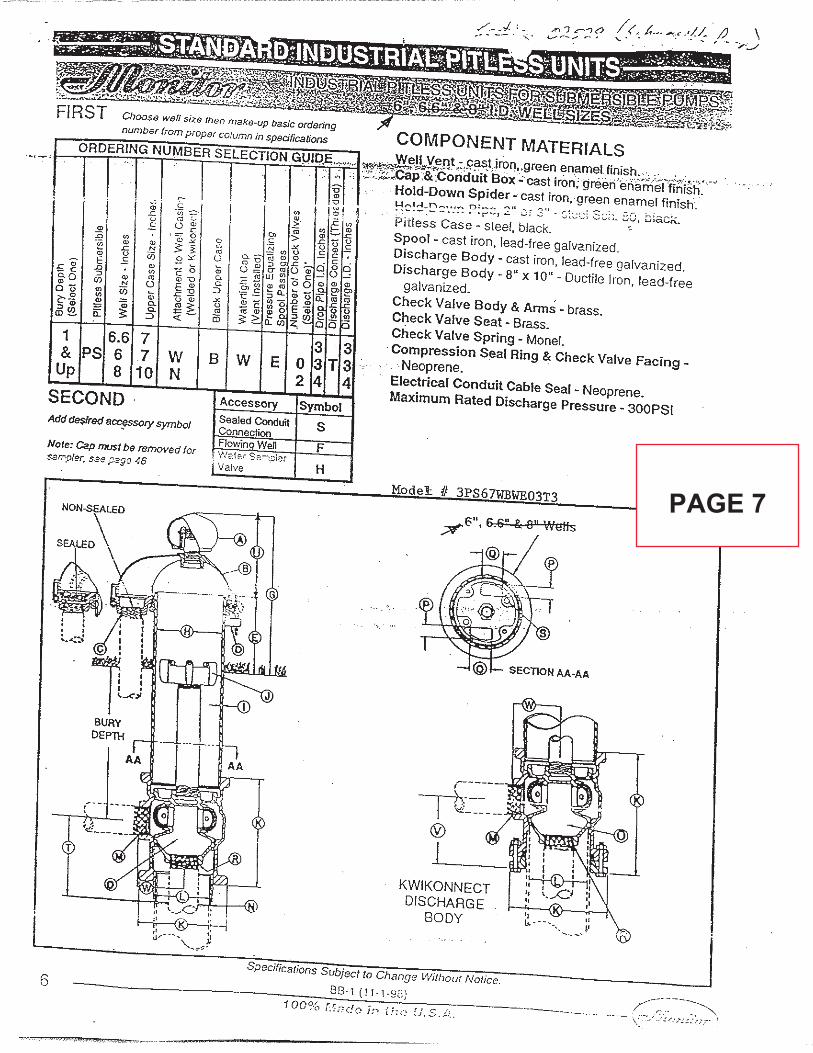
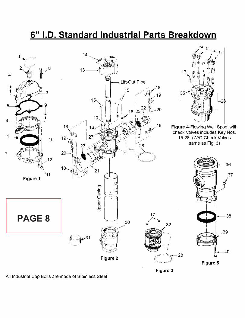
a. Pitless Adapter: Baker Monitor, Model No. 3PS67NBWE03T3 or equal. See“Existing Irrigation Well Information” document for additional information.Additional manufacturer information can be found at:“https://www.bakermonitor.com/content/standard-pitless-units/6-id-standard-industrial-pitless-units”
5. Sand Separator and Associated Components:a. See the “Existing Irrigation Well Information” documentation for additional
information on the items listed below.b. Existing sand separator: PuroFlex PF-61-020.c. Existing piping, valves, and other components.c. Piping, valves, and fittings (joints, unions, flanges): Bronze gate and check valves -
MSS SP-80, butterfly valves - MSS SP-6, ball valves threaded - MSS SP-110.d. Steel pipe: Galvanized Schedule 40. Threaded joints shall have American Standard
taper pipe threads conforming to ASME B1.20.1.e. Copper Tube and Pipe: Brazed joints shall be made in conformance with AWS
B2.2/B2.2M, ASME B16.50, and CDA A4015 with flux and are acceptable for allpipe sizes. Soldered joints shall be made with flux and are only acceptable forpiping 2 inches and smaller. Soldered joints shall conform to ASME B31.5 and CDAA4015.
f. Dissimilar Pipe Materials: Connections between ferrous and non-ferrous copperwater pipe shall be made with dielectric unions or flange waterways. Dielectricwaterways shall have temperature and pressure rating equal to or greater than thatspecified for the connecting piping. Waterways shall have metal connections on bothends suited to match connecting piping. Dielectric waterways shall be internallylined with an insulator specifically designed to prevent current flow betweendissimilar metals. Dielectric flanges shall meet the performance requirementsdescribed herein for dielectric waterways.
g. Provide piping support using industry and workmanship best practices. Installationof pipe hangers, inserts and supports shall conform to MSS SP-58 and MSS SP-69.
h. Piping shall be installed using industry and workmanship best practices to replace theexisting piping configuration as shown in the “Existing Irrigation Well Information”documentation. Pipe shall be accurately cut and worked into place without springingor forcing. Change in direction shall be made with fittings.
C. The Work: The Work shall include, but shall not be limited to the following (not necessarilyin the order indicated) to provide a fully functional irrigation system well water supply at thecompletion of the work:
TIME RESTRICTION ON PERFORMANCE OF WORK:

36C78619Q0453
Page 3 of 9
1. The Contractor is restricted to a maximum of five (5) continuous working days to replacethe well pump and pump motor to minimize the stress on and damage to the turfgrass andlandscaping. The work involves shutting down the entire active irrigation system whichmaintains 1.7 acres of turfgrass and 70 acres with landscaped areas, planting beds, andtrees.
2. The Contractor shall have equipment, materials, and supplies needed to complete the wellpump/pump motor replacement on-site and staged prior to starting work as describedherein. The COR shall verify the Contractor is ready to perform the work and hascoordinated the irrigation requirements as designated below.
3. Turfgrass areas are to be thoroughly irrigated the day prior to starting the well pumpreplacement under the direction of the COR and cemetery Gardener. Landscaped areas,planting beds and trees are to be irrigated the day before or as close to the day the wellwork begins as time allows under the direction of the COR and the cemetery Gardener.
4. If the Contractor fails to complete the work within the five (5) days as specified, theContractor, at their own expense, shall provide the means to water the turfgrass,landscaped areas, planter beds, and trees until the work has been completed.
5. The sand separator, piping, and valve work may be performed during the same timeperiod of the well pump/pump motor work OR during a completely separate five (5) dayperiod within the contract period of performance with the same restrictions as specifiedin paragraphs C.1 through C.4 above.
SUBMERSIBLE PUMP AND PUMP MOTOR REPLACEMENT:
6. Hoisting and rigging access is open (i.e. not enclosed) in the walled-off well yard locatedin the southwest corner of the cemetery, with room for staging removed sections. TheContractor is responsible for inventorying all items removed from the well and securinganything left overnight.
7. Remove the existing submersible, vertical turbine pump and pump motor, drop pipe, andelectrical cable from the well using a pump service rig and elevators of adequate capacityto safely handle the weight.
8. Removal and replacement of the drop pipe. The drop pipe shall be unscrewed or torchcut at the Contractor’s discretion. Demolished drop pipe shall be disposed of off-site thesame day that it is removed from the well.
9. New well equipment installation: The new submersible pump and pump motor, droppipe, and submersible pump electrical cable shall be installed in the well using a pumpservice rig and elevators of adequate capacity to safely handle the weight. Installationshall include all of the above listed major components and other associated componentsincluding but not limited to:

36C78619Q0453
Page 4 of 9
a. Mechanical and electrical connection of the pump, pump motor, drop pipe, andelectrical cable assembly.
b. Hoisting/rigging for the installation of the pump, pump motor, and associated piping.c. All labor, material, associated components, and equipment associated with testing the
completed assembly.d. Replace and install a new exterior grade, pressure gauge on exterior well cap located
on the pitless adapter. Match pressure range of existing pressure gauge.
10. Testing: After completion of all equipment, components, and material installations,perform a full system functional test and demonstrate to the COR the fulloperation/functionality of the newly replaced irrigation pump, pump motor, and theirrigation pump motor control unit has been fully coordinated with the existing irrigationcontrol system. Verify no leaks and all other well components are functioning correctly.
SAND SEPARATOR REPLACEMENT:
11. New sand separator installation:
a. Removal: As part of the overall piping and valve replacement, remove the existingPuroFlex sand separator, including the associated control box, electric dischargevalve, and discharge piping.
b. Install new sand separator: PuroFlex PF-61-020 or equal. See the “ExistingIrrigation Well Information” for the product cut sheet. Installation shall include anew manufacturer’s control box, new discharge valve, discharge piping and all newaccessories and fittings as required by the manufacturer as part of a completeinstallation.
c. Sand separator mounting: The new sand separator shall be mounted in the samelocation as the existing. Anchor the sand separator per the manufacturer’srequirements.
d. Install dielectric couplings at the main inlet and outlet connections (2 places) and atthe copper discharge line connection (1 place).
e. Install all new copper drain piping for the sand separator.f. Provide all electrical wiring, conduit, connections, and fittings for a complete
installation.
12. New piping, valves, and other piping component installation:
a. Removal: Removal all existing piping and components as indicated on theillustrations in the “Existing Irrigation Well Information” documentation.
b. Install new replacement piping, valves, flanges, hangers, braces, and other pipingcomponents:1) Install new SCH 40 galvanized steel piping in various sizes (1/2” to 3” Nominal
Diameter) to match the sizes of the existing piping being replaced.2) Install new 2” threaded bronze body ball valves (2 places). Size to match
existing.3) Install new 3” flanged, cast iron butterfly valve with EDPM seat and adjustable
36C78619Q0453
Page 5 of 9
flow control handle (1 place). Size to match existing. 4) Install new 3” threaded bronze check valve. Size to match existing.5) Install new flanges and flange gaskets on both sides of sensor T-fitting assembly.
Size to match existing.6) Install new T-fitting and all associated fittings for sensor installation. Provide
new flanges and piping. Size to match existing.7) Install new 3/4” threaded ball valve on exterior piping (located on building south
exterior). Size to match existing.8) Do not replace the expansion tank. Replace the inlet piping, valve, and coupling
in its entirety as indicated in the “Existing Irrigation Well Information”documentation. Do not replace the control piping as indicated.
9) Provide any additional fittings or piping as needed to complete the work.
13. The Contractor shall perform pressure and leakage tests for the new system for 2 hours to1.5 times the normal operating pressure. Leakage shall not exceed the followingrequirements:
a. Copper Tubing: No leaks.b. Ductile Iron Pipe: AWWA C600.
14. The work to replace the existing irrigation piping and valves shall be all inclusive torestore the irrigation system to its full functionality and operation.
15. After completion of all piping, components, equipment, fittings, accessories, andmaterial installations, perform a full system functional test and demonstrate to the COR thesatisfactory operation/functionality of the irrigation system sand separator, piping, valves,and piping accessories.
D. General Requirements and Conditions:1. Coordinate with the COR to locate all underground utilities, irrigation system lines, and
irrigation system components prior to start of work. All utilities and irrigation systemcomponents shall be traced and marked prior to any removal or demolition of work.
2. The construction access route to the cemetery shall be via the west maintenance accessroad from Fred Wilson Road – see cemetery site map. The inbound and outbound lanesof Mall Drive be maintained open at all times for visitors and funeral corteges. Whenother than normal business hours are approved in any case, all traffic control devicesshall be removed to allow normal traffic flow (one lane) the following morning (i.e. at7:00 am).
3. The Contractor is required to discontinue work sufficiently in advance of Easter Sunday,Mother's Day, Father's Day, Memorial Day, Veteran's Day and/or Federal holidays, topermit him to clean up all areas of operation adjacent to existing burial plots before thesedates.
4. Disposal of debris, trash, sediment, and other waste material created during the workshall be done at suitable disposal/recycling sites and in compliance with local, state, and
36C78619Q0453
Page 6 of 9
federal waste regulations. Haul away & dump all debris, sediment, and waste to an approved disposal site.
5. Availability and use of utility services: The Government shall make all reasonablyrequired amounts of water available to the Contractor from existing outlets and supplies.The Contractor, at Contractor's expense, shall install and maintain all necessarytemporary connections and distribution lines. Before final acceptance of the work by theGovernment, the Contractor shall remove all the temporary connections, distributionlines, and associated paraphernalia. No other utility services will be provided by theGovernment.
6. Remove, cut, alter, replace, patch and repair existing work as necessary to perform thework. Existing work to be altered or extended and that is found to be defective in anyway, shall be reported to the COR before it is disturbed. Materials and workmanship usedin restoring work shall conform in type and quality to that of original existingconstruction, except as otherwise shown or specified.
7. The Contractor shall preserve and protect all structures, equipment, and vegetation (suchas trees, shrubs, and grass) on or adjacent to the work site not to be removed and do notunreasonably interfere with the work required under this contract. If any limbs orbranches of trees are broken during contract performance, or by the careless operation ofequipment, or by workmen, the Contractor shall trim those limbs or branches with a cleancut and paint the cut with a tree-pruning compound as directed by the ContractingOfficer.
8. The Contractor shall protect from damage all existing improvements and utilities at ornear the work site and on adjacent property of a third party, the locations of which aremade known to or should be known by the Contractor. The Contractor shall repair anydamage to those facilities, including those that are the property of a third party, resultingfrom failure to comply with the requirements of this contract or failure to exercisereasonable care in performing the work. If the Contractor fails or refuses to repair thedamage promptly, the Contracting Officer may have the necessary work performed andcharge the cost to the Contractor.
9. All utilities required for the continuous operation of all existing facilities shall bemaintained in service at all times except when disruptions are needed. The Contractorshall inform the COR, Cemetery Director, and the Contracting Officer (CO) in writingfor such disruptions and obtain approval from the CO in writing at least 2 weeks prior tosuch need. When option exists, implement options to minimize interruption of services tothe facilities.
10. The Contractor shall coordinate with the COR and Cemetery Director for parking,material storage, temporary portable restroom facilities, and any other needs for thework. Public access to the National Cemetery shall not be impaired. Do not storematerials and equipment in other than assigned areas. The Contractor shall confine alloperations (including storage of materials) on Government premises to approved areas

36C78619Q0453
Page 7 of 9
11. The Contractor shall assume sole responsibility for safety of all persons on or about theconstruction site, in accordance with applicable laws and codes. Guard all materials inaccordance with the safety provisions according to OSHA and Associated GeneralContractors of America (AGC). Prior to commencing work, general contractor shallprovide proof that an OSHA certified “competent person” (CP) (29 CFR 1926.20(b)(2)will maintain a presence at the work site whenever the general or subcontractors arepresent.
12. Thoroughly clean up the work area at the end of each day’s work, and at completion ofthe project. Leave premises clean and free of waste, scrap, used equipment, or othermaterial intentionally or incidentally delivered to the site by Contractor or Contractor’spersonnel.
13. Upon completion of work, the Contractor Superintendent and the COR shall inspect thecompleted work for compliance with both the contract and the product manufacturer’srequirements. COR shall report unsatisfactory conditions in writing to the ContractingOfficer. The work shall not be accepted until all unsatisfactory conditions have beencorrected to the satisfaction of the Contracting Officer and the COR.
E. STANDARDS OF EMPLOYEE CONDUCT:a. The National Cemetery Administration honors veterans with a final resting place and
lasting memorials that commemorate their service to our Nation. National Cemeteries arenational shrines. The standards of work, appearance, and procedures performed by thecontractor at this cemetery shall reflect this nation’s concern for those interred there. Dueto the sensitive mission of the cemetery, contractor personnel must exercise and exhibitabsolute decorum, composure, and stability at all times.
b. Contractor personnel shall be required to adhere to the following standards of dress andconduct, as briefly mentioned here, while performing work in the National Cemetery.These standards and regulations are enforceable under Title 38, U.S.C., Part I, Chapter 9,Section 5901.
c. Clothing shall be presentable and suitable to the work while maintaining properappearance and decorum indicative for a National Shrine. Uniform shirts and hats arepreferred. Clothing shall be clean and cleanliness and personal hygiene are imperative. T-shirts and/or tank tops as outer garments are prohibited. Protective/safety clothing andshoes shall meet or exceed OSHA and state requirements.
d. Behavior and language must be appropriate, reverent, and respectful at all times.e. Eating and drinking (except water) is prohibited in the work areas and within sight of a
committal shelter during a service.f. Use of intoxicating beverages, any tobacco products, and illegal drugs on the Cemetery
premises is strictly prohibited.g. Contractor personnel shall not lean, sit, or stand on or against headstones or monuments.
No tools, equipment or other items will be placed or leaned on headstones or monuments.h. The Contractor shall be responsible for maintaining satisfactory standards of personnel
conduct and work performance and shall administer disciplinary action as required. TheContractor is expected to remove any employees from the Cemetery for cause, to include,
36C78619Q0453
Page 8 of 9
but not limited to, safety violations, other misconduct in performance of duty under these specifications and/or conduct contrary to the best interests of the Government. If the Contractor fails to act in this regard, or the reason for a removal is immediately required to protect the interests of the Government, the COR may direct the removal of an employee from the premises. Contractor objections to any such action will be referred to the Contacting Officer (CO) for final resolution; however, the Contractor will first immediately comply with COR direction pending any CO final resolution at a later time or date. The Contractor will not be due any type of compensation for their costs incurred as a result of an employee being removed for cause; unless the removal is directed by the COR and is later found invalid and/or unreasonable by the Contracting Officer.
F. Time of Completion: This project has a work performance TIME RESTRICTION – seeParagraphs C.1 through C.5 of the Statement of Work. The project shall be completed within45 calendar days after contract Notice of Award. Work outside of the Cemetery’s normaloperating hours of 7:00 am to 4:30 pm, Monday through Friday, excluding observed FederalHolidays, will not be permitted without prior approval of the COR. Requests shall besubmitted at least three (3) working days in advance. The Contractor shall not commenceperformance of work until the Contracting Officer has conducted a preconstruction meetingor has advised the Contractor that a preconstruction meeting is not required.
G. Code Compliance: All work shall be performed in accordance with the specifications. Itshall be the Contractor's responsibility to comply with all the applicable local, state andfederal laws and regulations. The Contractor shall apply and obtain all applicable permits tocomply with local, State and Federal regulations and requirements. The Contractor shallremove and dispose of all waste materials and construction debris and comply with allapplicable local, State and Federal regulations and requirements. All waste materials anddebris specified shall be removed from the Cemetery grounds by the Contractor at its ownexpenses, including all applicable permits and fees.
H. Contractor Quality Control:
1. The Contractor shall guarantee that all work done under this contract shall be free fromdefaults and no faulty workmanship with one (1) year warranty. Contractor shall ensureall appropriate paperwork is submitted to the manufacturer to receive the warranty. TheContractor hereby agrees to repair or replace deficiencies within 14 calendar days ofnotification by the direction of the CO at Contractor's own expense and shall be correctedto the satisfaction of the Government.
2. Contractor Supervisor/Superintendent: A competent and experienced English-speakingContractor Supervisor/Superintendent shall be provided by the Contractor wheneverwork is being performed - other than trash and debris pick-up.
3. The Contractor Supervisor shall review and approve submittals, ensure all specificationsare being met, inspect the quality of work performed, ensure contract work does notconflict with ceremonies and funerals, ensure employees are is adequately supervised and

36C78619Q0453
Page 9 of 9
proper conduct maintained, and certify the completed work for payment and other purposes.
I. Submittals After Award:
1. Submit manufacture’s literature, samples, cut sheets, and shop drawings to the COR forreview and approval.
2. Detailed Work Plan. The Contractor shall provide in writing a detailed work plan whichpresents the Contractor’s plan for completing the work. The Contractor’s plan shall beresponsive with the Statement of Work and describe, in detail, the approach to be usedfor each task required. For each task, the Contractor shall identify all necessary subtasks(if any), and milestone dates. The Contractor’s work plan shall be submitted to andapproved by the Contracting Officer prior to the start of on-site work.
J. Plans/Specifications/Supporting Documentation:1. “Existing Irrigation Well Information”.
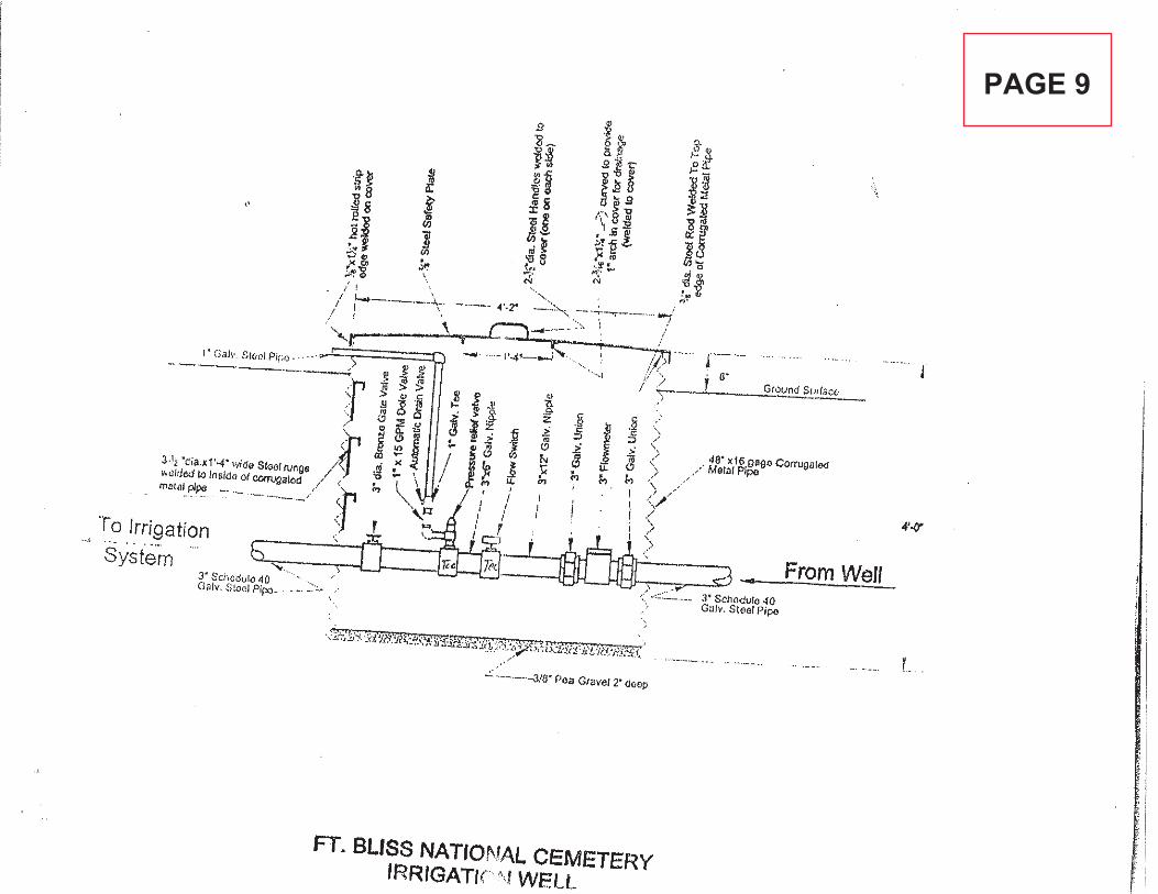
a. Fort Bliss National Cemetery Overall Site Mapb. Irrigation Well Site and Maintenance Yard Mapc. Irrigation Well Configuration As-built Diagramd. Goulds Vertical Turbine Submersible Well Pump and Pump Motor Specse. Baker Monitor, Pitless Adapter Specs and Parts Diagramf. Irrigation Well Piping Diagram and Configurationg. Puroflux PF61-020 Sand Separator Specs (for both new and existing)h. Irrigation Sand Separator, Piping, and Valve Replacement Guide
K. Project completion: The project site shall be protected and/or restored to a condition equal tothat existing prior to the commencement of work. Upon completion of contract, deliver workcomplete and undamaged. Existing work disturbed or removed as a result of performingrequired new work, shall be patched, repaired, reinstalled, or replaced with new work, andrefinished and left in as good condition as existed before commencing work.
END OF STATEMENT OF WORK

Existing Irrigation Well Information
REPLACE SUBMERSIBLE IRRIGATION PUMP AND SAND SEPARATOR
Fort Bliss National Cemetery El Paso, TX
Prepared by:
Rodney Duich, P.E. NCA Continental District
Department of Veterans Affairs
36C78619Q0453
Table of Contents
Title Page . . . . . . . . . . . . . . . . . . . . . . . . . . . . . . . . . . . . . . . . . . . . . . . . . . . . . . . . . . . . . . . . . . 1 Table of Contents . . . . . . . . . . . . . . . . . . . . . . . . . . . . . . . . . . . . . . . . . . . . . . . . . . . . . . . . . . . . 2 Fort Bliss National Cemetery Overall Site Map. . . . . . . . . . . . . . . . . . . . . . . . . . . . . . . . . . . . 3 Irrigation Well Site and Maintenance Yard Map . . . . . . . . . . . . . . . . . . . . . . . . . . . . . . . . . . 4 Irrigation Well Configuration As-built Diagram . . . . . . . . . . . . . . . . . . . . . . . . . . . . . . . . . . . 5 Goulds Vertical Turbine Submersible Well Pump and Pump Motor Specs . . . . . . . . . . . . . 6 Baker Monitor, Pitless Adapter Specs and Parts Diagram . . . . . . . . . . . . . . . . . . . . . . . . . 7, 8 Irrigation Well Piping Diagram and Configuration . . . . . . . . . . . . . . . . . . . . . . . . . . . . . . . . . 9 Puroflux PF61-020 Sand Separator Specs (For both new and existing) . . . . . . . . . . 10, 11, 12 Irrigation Sand Separator, Piping, and Valve Replacement Guide. . . . . 13, 14, 15, 16, 17, 18

WORK SITE:IRRIGATION WELL LOCATIONCONSTRUCTION
ENTRANCE
CONSTRUCTIONACCESS ROUTE
Fort Bliss National Cemetery Site Map
PAGE 3
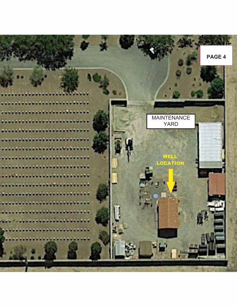
MAINTENANCE YARD
PAGE 4
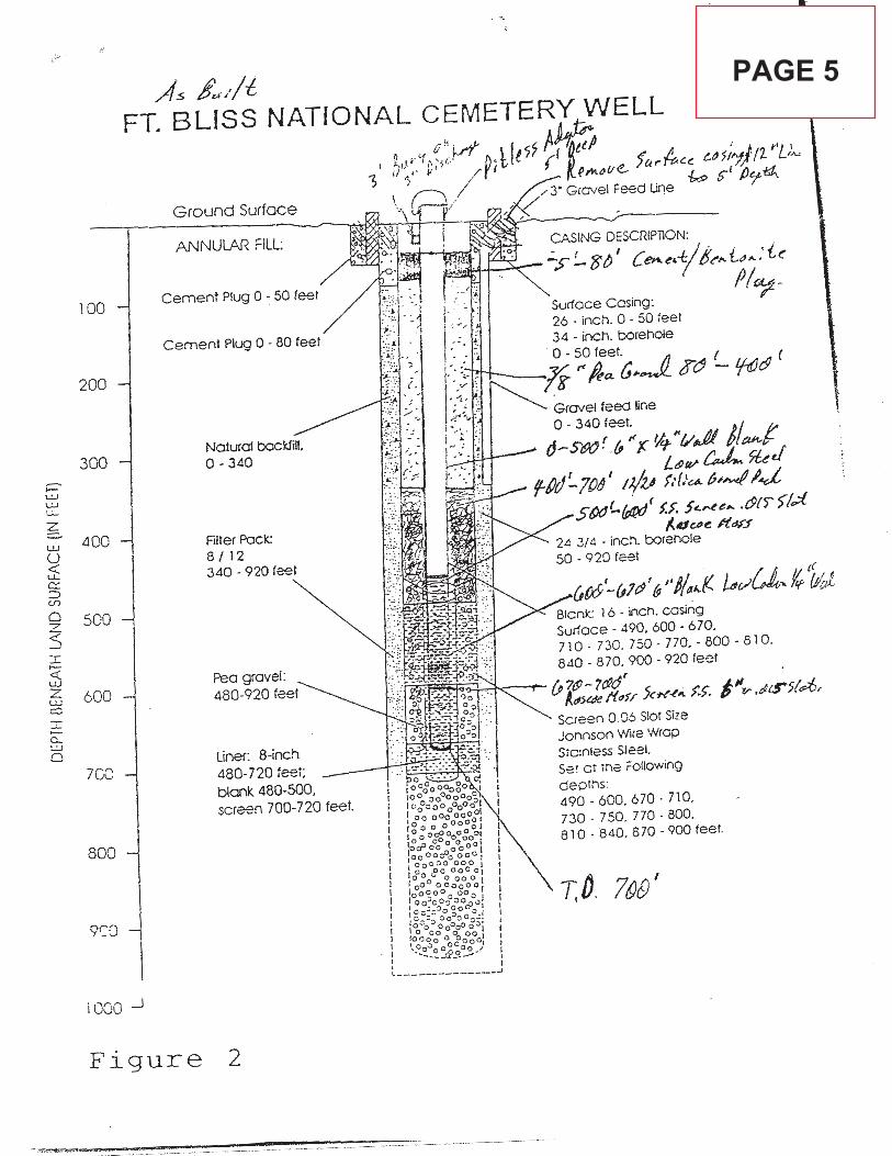
PAGE 5
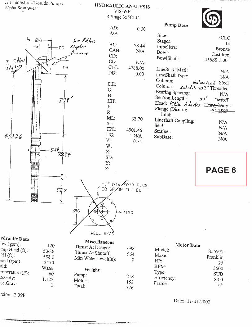
PAGE 6
PAGE 7
PAGE 8
PAGE 9

Puroflux Corporation • (805) 579-0216 • Fax (805) 579-6005 Rev. D 10/09
P U R O F L U X C O R P O R A T I O N
E N G I N E E R I N G M A N U F A C T U R I N G S E R V I C E
PF61-020 SPECIFICATION SHEET – 2” THREADED SEPARATOR
SPECIFICATIONS PF61-020
Flow Range 65-135 gpm
Connections – Influent / Effluent 2” mpt
Purge Outlet 1” fpt
Manual Air Bleed Valve 1/4” fpt
Volume 7 gal
Est. Weight, Dry 74 lbs
Est. Weight, Operating 125 lbs
Options:
Manual Purge
Wall Mounting Brackets / Legs
Inspection Port Consult Factory
Carbon steel construction
Fusion bonded polyester coating
True tangential entry
150 psi working pressure
Industrial grade manual purge valve
0 to 160 psi gauges on influent / effluent
1/4” manual air bleed valve
Five year limited warranty
PRESSURE DROP vs. FLOW RATE
Pressure Drop 3 psi 4 psi 6 psi 8 psi 10 psi 12 psi CV Factor
Flow (gpm)* 67 77 95 109 122 134 38.6
* (Flow rate / CV values may vary slightly)
To determine the approximate pressure drop at flow rates not shown in this chart, use the following formula: P = (FLOW RATE / CV) 2
CV Factor : CV is defined as the flow in gallons per minute (GPM) that will produce a one pound pressure drop across the separator.
PAGE 10

1. DIMENSIONS ARE IN INCHES2. DIMENSIONS MAY VARY SLIGHTLY - DO NOT USE FOR CONSTRUCTION3. SEPARATOR SYSTEM IS RATED FOR 150 PSI WORKING PRESSURE4. VESSEL CONSTRUCTION: CARBON STEEL TANK
EPOXY COATED EXTERIOR
NOTES: UNLESS OTHERWISE SPECIFIED
PUROFLUXC O R P O R A T I O N
CONTROL PANELNEMA 4X, FGHOA SWITCH
INLET/OUTLETPRESSURE GAUGES
MANUAL AIR RELIEF.25 BALL VALVE
ELECTRIC ACTUATORAUTOMATIC PURGE
1.00 PURGE
13.00
8.00
3.81
8.00
36.63
2.00 OUTLET
2.00 INLET
D
C
B
A
B
C
D
1235678
8 7 6 5 4 3 2 1
E
F
E
F
SHEET
CSIZE
A
CAGE CODE DWG NO. REV
PHONE: (805) 579-0216
FAX: (805) 579-6005
WEBSITE: www.puroflux.com
SCALE
PROJ NO.
DRAWN
CHECKED
DESIGN APPROVED
MFG APPROVED
QA APPROVED
RELEASE DATEDO NOT SCALE DRAWING
THE INFORMATION CONTAINED IN THISDRAWING IS THE SOLE PROPERTY OFPUROFLUX CORPORATION. ANY REPRODUCTION IN PART OR AS A WHOLEWITHOUT THE WRITTEN PERMISSION OFPUROFLUX CORPORATION IS PROHIBITED.
PROPRIETARY AND CONFIDENTIAL
NEXT ASSY
APPLICATION
DIMENSIONS ARE IN INCHESTOLERANCES:FRACTIONALANGULAR: MACH BEND TWO PLACE DECIMAL THREE PLACE DECIMAL
INTERPRET GEOMETRICTOLERANCING PER:
MATERIAL
FINISH
UNLESS OTHERWISE SPECIFIED
REVISIONS
DATEDESCRIPTIONREV APPROVED
NONE
PF61-020-AP HYDROCYCLONE SEPARATOR65-135 GPM - AUTO PURGEK. CARTER
02-04-02
611-0019 B
B UPDATED TO SOLIDWORKS 06-12-09 D.L.
OF1 2
PAGE 11

PAGE 12
EXISTING IRRIGATION WELL INFORMATION
REPLACE SUBMERSIBLE IRRIGATION PUMP AND SAND SEPARATOR
Irrigation Sand Separator, Piping, and Valve Replacement Guide
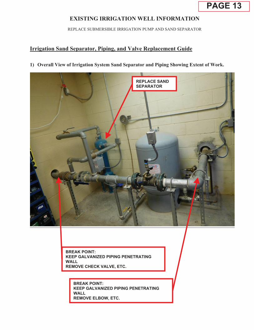
1) Overall View of Irrigation System Sand Separator and Piping Showing Extent of Work.
REPLACE SAND SEPARATOR
BREAK POINT: KEEP GALVANIZED PIPING PENETRATING WALL REMOVE CHECK VALVE, ETC.
BREAK POINT: KEEP GALVANIZED PIPING PENETRATING WALL REMOVE ELBOW, ETC.
PAGE 13

EXISTING IRRIGATION WELL INFORMATION
REPLACE SUBMERSIBLE IRRIGATION PUMP AND SAND SEPARATOR
Irrigation Sand Separator, Piping, and Valve Replacement Guide - Continued 2) Overall View of Irrigation System Sand Separator and Piping – Additional Information.
REPLACE SAND SEPARATOR
REPLACE ALL PIPING AND VALVES ON THIS SIDE OF EXPANSION TANK
DO NOT REPLACE PIPING ON THIS SIDE OF EXPANSION TANK
BREAK POINT: DO NOT REPLACE EXPANSION TANK
PAGE 14

EXISTING IRRIGATION WELL INFORMATION
REPLACE SUBMERSIBLE IRRIGATION PUMP AND SAND SEPARATOR
Irrigation Sand Separator, Piping, and Valve Replacement Guide - Continued 3) Detail: Sand Separator Installation
REPLACE SAND SEPARATOR
PROVIDE NEW AUTOMATICALLY CONTROLLED FLUSH VALVE
PROVIDE NEW ELECTRICAL CONTROLS AND BOX
ANCHOR/MOUNT/ATTACH THE SAND SEPARATOR IAW THE MANUFACTURER’S REQUIREMENTS
REPLACE DRAIN PIPING AND INSTALL DIELECTRIC COUPLING
PAGE 15

EXISTING IRRIGATION WELL INFORMATION
REPLACE SUBMERSIBLE IRRIGATION PUMP AND SAND SEPARATOR
Irrigation Sand Separator, Piping, and Valve Replacement Guide - Continued 4) Detail: Well Cap Gasket and Pressure Gauge
REPLACE PRESSURE GAUGE
PAGE 16
EXISTING IRRIGATION WELL INFORMATION
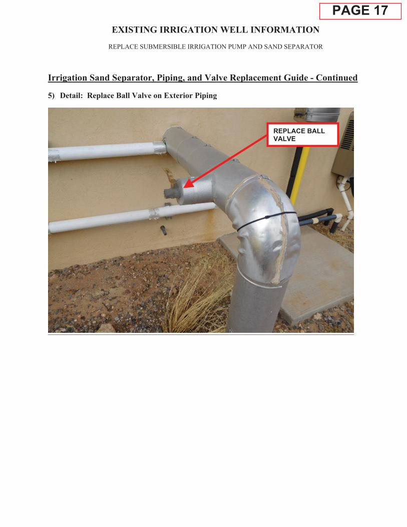
REPLACE SUBMERSIBLE IRRIGATION PUMP AND SAND SEPARATOR
Irrigation Sand Separator, Piping, and Valve Replacement Guide - Continued 5) Detail: Replace Ball Valve on Exterior Piping
REPLACE BALL VALVE
PAGE 17

EXISTING IRRIGATION WELL INFORMATION
REPLACE SUBMERSIBLE IRRIGATION PUMP AND SAND SEPARATOR
Irrigation Sand Separator, Piping, and Valve Replacement Guide - Continued 6) Additional Piping System Photographs
REPLACE EXPANSION TANK PIPING AND VALVES INSTALL DIELECTRIC COUPLING HERE
REPLACE ALL ASSOCIATED SENSOR PIPING, FLANGES, AND FITTINGS
PAGE 18