attachments b-d, to l-11-107, reply to request for
TRANSCRIPT

Enclosure B
Davis-Besse Nuclear Power Station (DBNPS), Unit No. 1
Letter L-11-107
AREVA NP Document 86-910440-000
Fracture Mechanics Analysis of Postulated Underclad Cracks in theDB-1 Reactor Vessel for 60 Years
30 pages
not including cover sheet
Controlled Document0402-01-FOl (20697) (Rev. 014, 04/13/2009)
NON-PROPRIETARY
A CALCULATION SUMMARY SHEET (CSS)AREVA
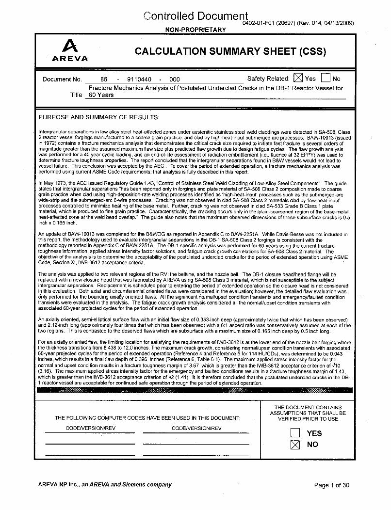
Document No. 86 - 9110440 - 000 Safety Related: N Yes E]No
Fracture Mechanics Analysis of Postulated Underclad Cracks in the DB-1 Reactor Vessel forTitle 60 Years
PURPOSE AND SUMMARY OF RESULTS:
Intergranular separations in low alloy steel heat-affected zones under austenitic stainless steel weld claddings were detected in SA-508, Class2 reactor vessel forgings manufactured to a coarse grain practice, and clad by high-heat-input submerged arc processes. BAW-10013 (issuedin 1972) contains a fracture mechanics analysis that demonstrates the critical crack size required to initiate fast fracture is several orders ofmagnitude greater than the assumed maximum flaw size plus predicted flaw growth due to design fatigue cycles. The flaw growth analysiswas performed for a 40 year cyclic loading, and an end-of-life assessment of radiation embrittlement (i.e., fluence at 32 EFPY) was used todetermine fracture toughness properties. The report concluded that the intergranular separations found in B&W vessels would not lead tovessel failure. This conclusion was accepted by the AEC . To cover the period of extended operation, a fracture mechanics analysis wasperformed using current ASME Code requirements; that analysis is fully described in this report.
In May 1973, the AEC issued Regulatory Guide 1.43, "Control of Stainless Steel Weld Cladding of Low-Alloy Steel Components". The guidestates that intergranular separations "has been reported only in forgings and plate material of SA-508 Class 2 composition made to coarsegrain practice when clad using high-deposition-rate welding processes identified as 'high-heat-input' processes such as the submerged-arcwide-strip and the submerged-arc 6-wire processes. Cracking was not observed in clad SA-508 Class 2 materials clad by 'low-heat-input'processes controlled to minimize heating of the base metal. Further, cracking was not observed in clad SA-533 Grade B Class 1 platematerial, which is produced to fine grain practice. Characteristically, the cracking occurs only in the grain-coarsened region of the base-metalheat-affected zone at the weld bead overlap." The guide also notes that the maximum observed dimensions of these subsurface cracks is 0.5inch x 0.165 inch.
An update of BAW-10013 was completed for the B&WOG as reported in Appendix C to BAW-2251A. While Davis-Besse was not included inthis report, the methodology used to evaluate intergranular separations in the DB-1 SA-508 Class 2 forgings is consistent with themethodology reported in Appendix C of BAW-2251A. The DB-1 specific analysis was performed for 60-years using the current fracturetoughness information, applied stress intensity factor solutions, and fatigue crack growth correlations for SA-508 Class 2 material. Theobjective of the analysis is to determine the acceptability of the postulated underclad cracks for the period of extended operation using ASMECode, Section XI, IWB-3612 acceptance criteria.
The analysis was applied to two relevant regions of the RV: the beltline, and the nozzle belt. The DB-1 closure head/head flange will bereplaced with a new closure head that was fabricated by AREVA using SA-508 Class 3 material, which is not susceptible to the subjectintergranular separations. Replacement is scheduled prior to entering the period of extended operation so the closure head is not consideredin this evaluation. Both axial and circumferential oriented flaws were considered in the evaluation; however, the detailed flaw evaluation wasonly performed for the bounding axially oriented flaws. All the significant normal/upset condition transients and emergency/faulted conditiontransients were evaluated in the analysis. The fatigue crack growth analysis considered all the normal/upset condition transients withassociated 60-year projected cycles for the period of extended operation.
An axially oriented, semi-elliptical surface flaw with an initial flaw size of 0.353-inch deep (approximately twice that which has been observed)and 2.12-inch long (approximately four times that which has been observed) with a 6:1 aspect ratio was conservatively assumed at each of thetwo regions. This is contrasted to the observed flaws which are subsurface with a maximum size of 0.165 inch deep by 0.5 inch long.
For an axially oriented flaw, the limiting location for satisfying the requirements of IWB-3612 is at the lower end of the nozzle belt forging wherethe thickness transitions from 8.438 to 12.0 inches. The maximum crack growth, considering normal/upset condition transients with associated60-year projected cycles for the period of extended operation (Reference 4 and Reference 5 for 114 HU/CDs), was determined to be 0.043inches, which results in a final flaw depth of 0.396 inches (Reference 6, Table 6-1). The maximum applied stress intensity factor for thenormal and upset condition results in a fracture toughness margin of 3.67 which is greater than the IWB-3612 acceptance criterion of 4/10(3.16). The maximum applied stress intensity factor for the emergency and faulted conditions results in a fracture toughness margin of 1.43,which is greater than the IWB-3612 acceptance criterion of ,/2 (1.41). It is therefore concluded that the postulated underclad cracks in the DB-1 reactor vessel are acceptable for continued safe operation through the period of extended operation.
THE DOCUMENT CONTAINSASSUMPTIONS THAT SHALL BE
THE FOLLOWING COMPUTER CODES HAVE BEEN USED IN THIS DOCUMENT: VERIFIED PRIOR TO USE
CODENERSION/REV CODENERSION/REV YES
~NO
AREVA NP Inc., an AREVA and Siemens company Page 1 of 30
1`10111ed Document
A 0402-01-FOl (20697) (Rev. 014, 04/13/2009)AR EVAAR.. EVA N , Document No. 86-9110440-000AREVA NP Inc.,
an AREVA and Siemens company
NON-PROPRIETARY
Fracture Mechanics Analysis of Postulated Underclad Cracks in the DB-1 Reactor Vessel for 60 Years
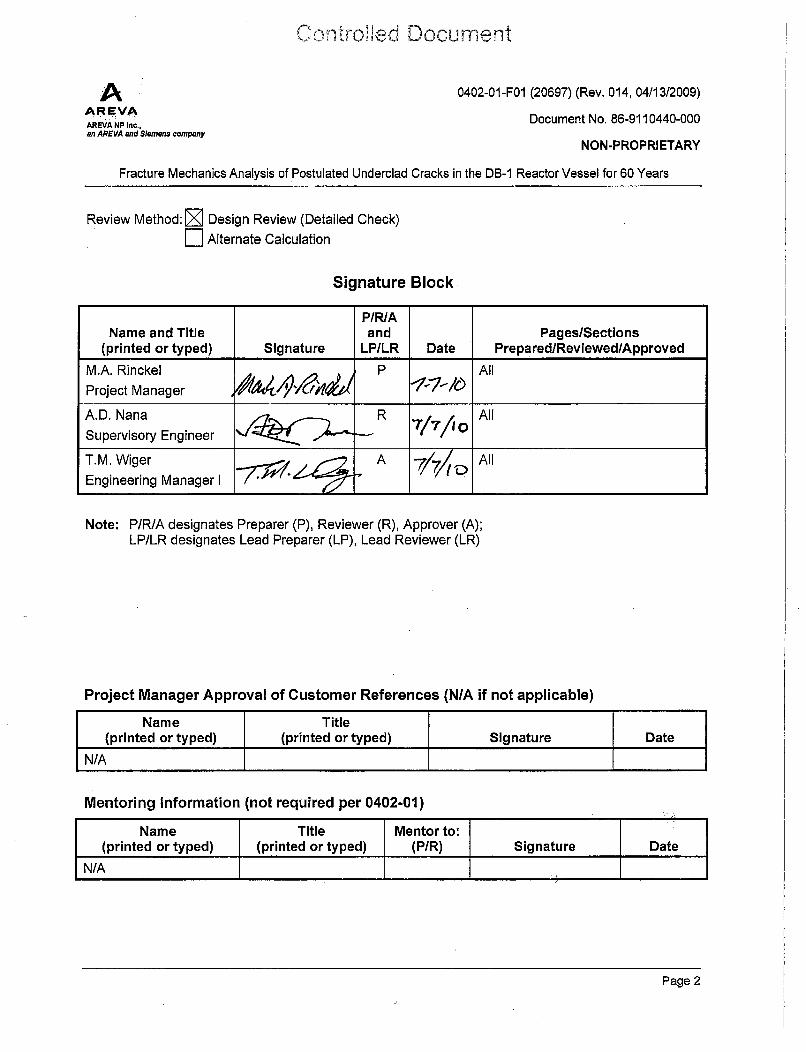
Review Method: ýq Design Review (Detailed Check)
F Alternate Calculation
Signature Block
P/R/AName and Title and Pages/Sections
(printed or typed) Signature LP/LR Date Prepared/Reviewed/Approved
M.A. Rinckel P All
Project Manager 41 -146/_A.D. Nana R All
Supervisory Engineer .Q
T.M. Wiger A 7/7/t P All
Engineering Manager I
Note: P/RJA designates Preparer (P), Reviewer (R), Approver (A);LP/LR designates Lead Preparer (LP), Lead Reviewer (LR)
Project Manager Approval of Customer References (N/A if not applicable)
Name Title(printed or typed) (printed or typed) Signature Date
N/A
Mentoring Information (not required per 0402-01)
Page.2

Controlled Document
AAR EVAAREVA NP Inc.,an AREVA and Siemens company
0402-01-FOl (20697) (Rev. 014, 04/13/2009)
Document No. 86-9110440-000
NON-PROPRIETARY
Fracture Mechanics Analysis of Postulated Underclad Cracks in the DB-1 Reactor Vessel for 60 Years
Record of Revision
Revision PageslSectionslNo. Date Paragraphs Changed Brief Description / Change Authorization
000 07/2010 All Original release
-I- t
F ± I
+ +
F + +
-I- I
i + +
Page 3

Controlled Document
A Document No. 86-9110440-000AREVAAREVA NP Inc.,an AREVA and Siemens company NON-PROPRIETARY
Fracture Mechanics Analysis of Postulated Underclad Cracks in the DB-1 Reactor Vessel for 60 Years
Table of ContentsPage
SIGNATURE BLOCK ................................................................................................................................ 2
RECORD OF REVISION .......................................................................................................................... 3
L IS T O F T A B L E S ..................................................................................................................................... 6
L IS T O F F IG U R E S ................................................................................................................................... 7
1 .0 IN T R O D U C T IO N ........................................................................................................................... 8
1 .1 B a c k g ro u n d ...................................................................................................................................... 8
1.1.1 B&W Investigations in BAW -1 001 3-A .......................................................................... 8
1.1.2 Regulatory Guide 1.43 .................................................................................................. 8
1 .2 P o stu la te d F law S iz e ......................................................................................................................... 9
1 .3 R e g io n s o f In te re st ........................................................................................................................... 9
2.0 ANALYTICAL M ETHODOLOGY ............................................................................................ 11
2.1 Postulated Surface Flaw ........................................................................................................... 11
2.2 Stress Intensity Factor Solutions ................................................................................................ 12
2.3 Effect of Cladding Material on Stress Intensity Factor .............................................................. 13
2.4 Fatigue Crack Growth Model ................................................................................................... 14
2.5 Fracture Toughness Curves ............................................................ ... ..................................... 15
2.6 Flaw Acceptance Criteria ........................................................................................................... 16
3.0 GEOMETRY, VESSEL MATERIALS AND MATERIAL PROPERTIES ................................... 17
3 .1 G e o m e try ........................................................................................................................................ 1 7
3.2 Thermal and Mechanical Properties .......................................................................................... 18
3.3 Nil-Ductility Reference Temperature ........................................................................................ 18
3 .4 T ra n s ie n ts ...................................................................................................................................... 1 9
3 .5 S tre s s e s ......................................................................................................................................... 2 0
3.5.1 Stresses for Operating Transients ............................................................................... 22
3.5.2 Discontinuity Factors ................................................................................................. 22
3.5.3 Stresses from Vessel Loads ........................................................................................ 23
3.5.4 Stresses from Nozzle Loads ...................................................................................... 25
3.5.5 Nozzle Interaction Stresses ........................................................................................ 25
4.0 SUM MARY OF RESULTS AND CONCLUSIONS ................................................................. 27
Page 4

Controlled Document
A Document No. 86-9110440-000AREVA NP Inc., "'on roor/,iy/,$an AREVA and Siemens company PROPRIE A/
Fracture Mechanics Analysis of Postulated Underciad Cracks in the DB-1 Reactor Vessel for 60 Years
Table of Contents
(continued)
Page
4.1 S um m ary of R esults [7] ................................................................................................................. 27
4 .2 C o n clu sio n s .................................................................................................................................... 2 7
5 .0 R E F E R E N C E S ............................................................................................................................ 2 9
Page 5
Controlled DocumentA
AR VA Document No. 86-9110440-000
AREVA NP Inc.,an AREVA and Siemens company NON-PROPRIETARY
Fracture Mechanics Analysis of Postulated Underclad Cracks in the DB-1 Reactor Vessel for 60 Years
List of Tables
Page
Table 3-1: Reactor Vessel Dim ensions [7] ........................................................................................ 17
Table 3-2: Reference Temperatures at 52 EFPY ............................................................................. 18
Table 3-3: Transient Events for Flaw Evaluation ............................................................................. 19
T a b le 4 -1: S um m a ry of R e sults ............................................................................................................. 2 8
Page 6
Controlled Document
ADAR EVA Document No. 86-9110440-000AREVA NP rnc.,
an AREVA and Siemens company PrOP
Fracture Mechanics Analysis of Postulated Underclad Cracks in the DB-1 Reactor Vessel for 60 Years
List of FiguresPage
Figure 1-1: Davis Besse Unit 1 Reactor Vessel ............................................................................... 10
Figure 2-1: Postulated Surface Flaw ................................................................................................. 11
Figure 3-1: Reactor Vessel Locations ............................................................................................. 21
Figure 3-2: Reactor Vessel Locations for General Shell Stresses .................................................... 24
Page 7

Controlled Document
AAREVA Document No. 86-9110440-000
AREVA NP Inc.,an AREVA and Siemens company NON-PROPRIETARY
Fracture Mechanics Analysis of Postulated Underclad Cracks in the DB-1 Reactor Vessel for 60 Years
1.0 INTRODUCTION
Beginning in 1970, reactor vessel manufacturers have been detecting intergranular separations in theheat-affected zones of low alloy steel SA-508 Class 2 forgings melted to coarse grain practice and cladwith austenitic stainless steel weld metal using high-heat-input submerged-arc welding processes. Afracture mechanics analysis, performed in 1971 to address this so-called underclad crackingphenomenon, demonstrated that the critical crack size required to initiate fast fracture was severalorders of magnitude greater than the maximum postulated flaw size plus predicted flaw growth over a40 year design life. This analysis utilized fracture toughness data based on radiation embrittlement atend-of-life conditions (i.e., fast neutron fluence at 32 EFPY). The final report, BAW-10013-A [1],concluded that postulated intergranular separations in B&W-designed vessels would not lead to vesselfailure. The present analysis updates the 1971 analysis for the Davis Besse Unit 1 (DB-1) reactorvessel using current ASME Code requirements and extends the operating period to 60 years. Insidesurface flaws are postulated to be present at several locations on the inside surface of the reactorvessel (RV) that are susceptible to underclad cracking. The analysis is performed to determine theacceptability of the postulated flaws under design basis loading conditions for the period of extendedoperation using the acceptance criteria of the ASME Boiler and Pressure Vessel Code, Section. XI,Article IWB-3612 [2]. The DB-1 underclad cracking evaluation for 60 years summarized herein isbased on the detailed calculation reported in Reference [7].
1.1 Background
Two key developments in the treatment of underclad cracking are the B&W investigations in BAW-10013-A and the issuance of Regulatory Guide 1.43
1.1.1 B&W Investigations in BAW-10013-A
The results of the B&W investigations in BAW-1 0013-A confirmed that intergranular separations subjectflaws only occur in SA-508 Class 2 forgings manufactured to a course grain practice and clad by high-heat-input submerged-arc welding processes such as the six-wire, strip, and the two-wire processes.Furthermore, these defects have only been detected in the heat-affected zone immediately below theclad/base metal interface and the size of these defects did not exceed 0.100 inch in depth and 0.500inch in length. A depth of 0.156 inch was used in the fracture mechanics analysis summarized in BAW-10013-A since it was the maximum discontinuity depth observed throughout the industry. Theinvestigations also noted that no anomalies were observed in SA-533 Grade B, Class 1 plate materialsclad by any of the high-heat-input welding processes.
1.1.2 Regulatory Guide 1.43
In May 1973, the Atomic Energy Commission issued Regulatory Guide 1.43 entitled "Control. ofStainless Steel Weld Cladding of Low-Alloy Steel Components," [3]. This guide states that "Undercladcracking has been reported only in forgings and plate material of SA-508 Class 2 composition made tocoarse grain practice when clad using high-deposition-rate welding processes identified as "high-heat-input" processes such as the submerged-arc wide-strip and the submerged-arc 6-wire processes.Cracking was not observed in SA-508 Class 2 materials clad by "low-heat-input" processes controlled.to minimize heating of the base metal. Further, cracking was not observed in clad SA-533 Grade BClass 1 plate material, which is produced to fine grain practice. Characteristically, the cracking occurs
Page 8

Controlled Document
AR Document No. 86-9110440-000AREVA NP Inc.,an AREVA and Siemens company NON-PROPRIETARY
Fracture Mechanics Analysis of Postulated Underclad Cracks in the DB-1 Reactor Vessel for 60 Years
only in the grain-coarsened region of the base-metal heat-affected zone at the weld bead overlap." Theguide also notes that the maximum size of these subsurface cracks is 0.5 inches x 0.165 inches.
1.2 Postulated Flaw Size
The size of the postulated underclad crack to be considered in the present fracture. mechanics analysisis conservatively taken as the maximum size of subsurface cracks noted in Regulatory Guide 1.43. Thesubsurface dimensions of the postulated underclad crack are therefore taken to be 0.165 inch in depthand 0.500 inch in length.
1.3 Regions of Interest
Based on the discussion above, the only regions of the reactor vessel that are susceptible to undercladcracking are those fabricated from SA-508 Class 2 forgings manufactured to a coarse grain practiceand clad by a high-heat-input submerged arc welding process. SA-508 Class 2 material is usedextensively in the DB-1 reactor vessel between the lower and upper heads, from the Dutchman forgingto the reactor vessel flange. The lower head is made from SA-533 Grade B modified plate materialwhich is not susceptible to underclad cracking. Furthermore, since the present fracture mechanicsanalysis for underclad cracking is intended to support licensing activities for plant operation beyond2017, and the present reactor vessel closure head is scheduled to be replaced in 2014 with a one-pieceSA-508 Class 3 forged head, the closure head region need not be considered further in the context ofthe present flaw evaluations for underclad cracking. Referring to Figure 1-1, the remaining regions ofinterest for the Davis Besse reactor vessel are:
a) Reactor vessel flange forging - SA-508 Class 2
b) Nozzle belt forging - SA-508 Class 2
c) Upper and lower shell forgings - SA-508 Class 2
d) Dutchman forging - SA-508 Class 2
Page 9

Controlled Document
AAREVAAREVA NP Inc.,an AREVA and Siemens company
Document No. 86-9110440-000
NON-PROPRIETARY
Fracture Mechanics Analysis of Postulated Underclad Cracks in the DB-1 Reactor Vessel for 60 Years
Reactor Vessel Flange
Nozzle Belt ForgingADB 203; 123Y317
Outlet Nozzle Forging
Weld WF-232 Inside 9%Weld WF-233 Outside 91%
Upper Shell Forging
AKJ 233 - 123X244
* - Weld WF-182-1
4 Lower Shell ForgingAKJ 233 - 123X244
. Weld WF-232 Inside 12%Weld WF-233 Outside 88%
Dutchman Forging1 22Y284VA1
Weld WF-1 82-1
Lower HeadC6168-3
Figure 1-1: Davis Besse Unit I Reactor Vessel
Page 10

Controlled Document
AAREV VA Document No. 86-9110440-000AREVA NP Inc.,an AREVA and Siemens company NON-PROPRIETARY
Fracture Mechanics Analysis of Postulated Underclad Cracks in the DB-1 Reactor Vessel for 60 Years
2.0 ANALYTICAL METHODOLOGY
Linear elastic fracture mechanics analysis is used to determine the acceptability of intergranularseparations in the heat-affected zone of coarse-grained SA-508 Class 2 forging material that has beenclad with austenitic stainless steel weld metal using a high-heat-input submerged-arc welding process.Although an underclad crack would be fully contained in the underlying base metal, it is conservativelypostulated that such a crack would extend through the cladding material to create a surface breakingflaw. These flaws may be oriented in both the longitudinal direction (lying in a radial plane of the reactorvessel) and circumferential direction (in a horizontal plane). It is further postulated that these flaw arelocated at the most highly stressed locations in the susceptible regions of the reactor vessel. Theapplied stresses from internal pressure and thermal gradients, determined by finite element stressanalysis using the ANSYS [4] and PCRIT [5] computer codes, and from external vessel and nozzleloads caused by deadweight, thermal expansion, seismic events, and loss of coolant accidents.Closed-form solutions from the literature are used to characterize the crack tip stress intensity factorsneeded for ASME Code flaw evaluations. Additional computation is performed to capture the effect onstress intensity factors of differential thermal expansions between the cladding and base metal. Aftercalculating fatigue crack growth under cyclic loads for the period of extended operation, the final flawsize is evaluated against the acceptance criteria of the ASME Code.
2.1 Postulated Surface Flaw
For purposes of analysis, an underclad crack is conservatively represented by the 6:1 semi-ellipticalsurface crack illustrated in Figure 2-1. Combining the design underclad flaw depth of 0.165 inch (fromSection 1.2) with a 0.188 inch nominal cladding thickness produces a 0.353 inch deep surface flaw.The 6:1 aspect ratio then produces a postulated flaw length of 2.118 inches, which is significantlygreater than the design length of 0.500 inch (from Section 1.2).
l 6:1 semi-elliptical
surface flaw length Not to scale01 5 eaainrgo0.165" separation region
7) // 0.353" flaw depth
0.188" cladding thicknessiF
Figure 2-1: Postulated Surface Flaw
Page 11

Controlled DocumentA
AR VA Document No. 86-9110440-000
AREVA NP Inc.,an AREVA and Siemens company NON-PROPRIETARY
Fracture Mechanics Analysis of Postulated Underclad Cracks in the DB-1 Reactor Vessel for 60 Years
2.2 Stress Intensity Factor Solutions
The Raju-Newman solution for an internal semi-elliptical axial surface flaw in a cylindrical vessel is usedas a general form of stress intensity factor equation for calculating crack tip stress intensity factors forarbitrary through-wall stress distributions. For a third-order stress distribution, expressed as
aY(x) = A0 + Aix + A2x2 + A3X
3
where "x" is the radial distance from the inside surface of the cylinder, the Raju-Newman [6] influencecoefficient solution for the stress intensity factor at the maximum flaw depth is
K, =_ i-.•GjAiaj
Qj=0
where
Q = flaw shape factor = 1 + 1.464(a/c)1 65
a = flaw depth
c = flaw half-length = 3a
Gj = influence coefficient corresponding to Aj stress term
The Gj influence coefficients for an inside surface axial flaw are provided in Table 1 of Reference [6] fort/Ri = 0.1 and several values of a/c and aft, where "t" is the wall thickness. Quadratic expressions havebeen developed [7] to accurately interpolate between the tabulated values.
Three variations of the above solution are used to calculate stress intensity factors, depending on thetype of load and the order of the available through-wall stressdistribution, as explained below.
a) Through-wall thermal gradient stresses are available from finite element stress analysis(ANSYS [4] and PCRIT [5]).
(TT = Ao + Aix + A 2 x 2 + A 3 x 3
KIT G=-I[GoAoa05 +G 1 Ala 15 +G 2 A2 a 2 .5 + G3 A 3 a3.]
b) Through-wall pressure stresses are available from finite element stress analysis (ANSYS [4]).
ap = B0 + Bax + B2 x 2 + B3 x 3
Using an additional constant term to account for pressure acting on the crack face,
KIp 1P [GO(Bo + 1)a0.5 + G 1Bla 1 5 + G 2 B2 a 2 5 + G 3 B3 a3"]
Page 12

Controlled Document
AAR EVAAREVA NP Inc.,an AREVA and Siemens company
Document No. 86-9110440-000
NON-PROPRIETARY
Fracture Mechanics Analysis of Postulated Underclad Cracks in the DB-1 Reactor Vessel for 60 Years
c) Surface stresses are available from beam-element vessel loading analysis, nozzle loads, andnozzle/shell interaction analysis. For these linear gradient stresses,
C'LG = CO + 0 1x
K1_LG=r- [GOC 0 a05+G1Clal5]
2.3 Effect of Cladding Material on Stress Intensity Factor
Although the one-dimensional finite element code PCRIT models the cladding in the thermal solution tocalculate temperatures, stresses are only calculated in the base metal, and not in the cladding itself.Thus the code does not consider stresses in the cladding when calculating stress intensity factors dueto thermal loading. To account for this cladding effect, an additional stress intensity factor, Kiclad, iscalculated separately and added to the stress intensity factor computed by PCRIT.
To identify the portion of the total stress intensity factor that is attributable to the presence of claddingand which is not considered by PCRIT, stress intensity factors are determined for two through-wallthermal stress distributions, one with and one "without" the effects of cladding. The term "withoutcladding" is used to describe the stress intensify factors currently calculated by PCRIT even though thebase metal stresses include the effects of differential thermal expansion between the base metal andcladding materials. At a given flaw depth, the stress intensity factor due to cladding, Klcjad, is thedifference between the stress intensity factors calculated with and without cladding.
Thermal stresses are calculated from PCRIT temperature output using the followingTimoshenko [8] for stress in a hollow cylinder,
equations from
Hoop stress:
Axial stress:
Ror r ]
Go= JTrdr + JTr dr-Tr2v0 (-'• ri) Ro2 "R-i Ri Ri
2 fTr dr - TI-R Ri
[ Ref. [8], Eqn. (255) ]
[ Ref. [8], Eqn. (256)]
where r = radial position
Ri = inner radius
R, = outer radius
T = temperature
Stress intensity factors are then calculated for each thermal stress distribution using the Raju-Newman[6] solution for KIT from Section 2.2.
Page 13

Controlled Document
AAR EVA Document No. 86-9110440-000
AREVA NP Inc.,an AREVA and Siemens company NON-PROPRIETARY
Fracture Mechanics Analysis of Postulated Underclad Cracks in the DB-1 Reactor Vessel for 60 Years
2.4 Fatigue Crack Growth Model
Flaw growth due to cyclic loading is calculated using the fatigue crack growth rate model from Article A-4300 of Section XI [2],
da_-- C, (A K )n,
dlN
where AKI is the stress intensity factor range in ksilin and da/dN is in inches/cycle. For a surface flaw ina water environment,
AKI = Klmax - Klmin
R = Klmr, n/Klmax
0 _<IR •< 0.25: AKI < 17.74,n = 5.95
C, = 1.02x10⁻¹² xSS= 1.0
AKI _> 17.74,n = 1.95
C. = 1.01 x 10⁻⁷ x SS= 1.0
0.25 < R < 0.65: AKI < 17.74 [ (3.75R + 0.06) / (26.9R - 5.725) ]0.25,
n = 5.95C. = 1.02x10⁻¹² xSS = 26.9R - 5.725
AKI _> 17.74 [ (3.75R + 0.06) / (26.9R - 5.725) ].25,
n = 1.95Co = 1.01 X 10⁻⁷X SS = 3.75R + 0.06
0.65•< R < 1.0: AKI < 12.04,n = 5.95
Co = 1.02x10⁻¹² xSS= 11.76
AKI _> 12.04,n= 1.95
Co= 1.01 X 10⁻⁷ x SS =2.5
Page 14

Controlled Document
AAREVA Document No. 86-9110440-000AREVA NP Inc.,
an AREVA and Siemens company NON-PROPRIETARY
Fracture Mechanics Analysis of Postulated Underclad Cracks in the DB-1 Reactor Vessel for 60 Years
Section XI [2] also specifies that the following in-air rates must be used if it is greater than the in-waterrates specified above.
n = 3.07Co = 1.99x10"10 xS
0•_ R < 1: S = 25.72 x (2.88 - R)-3°7
AKI = Klmax - Klmin
-2-<R<0: S 1AKI = Klmax
R<2: S= 1AK= (1 - R) x Klmax / 3
The fatigue crack growth calculations contain an explicit check to ensure that the maximum crackgrowth rate is used on the present flaw evaluations.
2.5 Fracture Toughness Curves
From Article A-4200 of Section XI [2], the lower bound Kia fracture toughness for crack arrest can beexpressed as
Kia = 26.8 + 12.445 exp [ 0.0145 (T - RTNDT)],
where T is the crack tip temperature, RTNDT is the nil-ductility reference temperature of the material, KIais in units of ksi,,in, and T and RTNDT are in units of OF. In the present flaw evaluations, K15 is limited to amaximum value of 200 ks[i/in (upper-shelf fracture toughness).
A higher measure of fracture toughness is provided by the Kic fracture toughness for crack initiation,approximated in Article A-4200 of Section XI [2] by
Kjc = 33.2 + 20.734 exp [ 0.02 (T - RTNDT)].
Page 15

Controlled Document
AAR EVAAREVA NP Inc.,an AREVA and Siemens company
Document No. 86-9110440-000
NON-PROPRIETARY
Fracture Mechanics Analysis of Postulated Underclad Cracks in the DB-1 Reactor Vessel for 60 Years
2.6 Flaw Acceptance Criteria
Article IWB-3612 of Section XI [2] requires that the applied stress intensity factor at the final flaw sizebe less than the available fracture toughness at the crack tip temperature, with appropriate safetyfactors, as described below.
For normal and upset conditions:
K,(af) < Ka/ 10V
where
K1(af) = the maximum applied stress intensity factor for normal and upset conditions atthe final flaw size af
KIa = the available fracture toughness based on crack arrest for the correspondingcrack tip temperature
For emergency and faulted conditions:
Ki(af) < Kir 1-F
where
KI(af) = the maximum applied stress intensity factor for emergency and faultedconditions at the final flaw size af
Kic = the available fracture toughness based on fracture initiation for thecorresponding crack tip temperature
Page 16
Controlled Document
AAREVA Document No. 86-9110440-000
AREVA NP Inc.,an AREVA and Siemens company NON-PROPRIETARY
Fracture Mechanics Analysis of Postulated Underclad Cracks in the DB-1 Reactor Vessel for 60 Years
3.0 GEOMETRY, VESSEL MATERIALS AND MATERIAL PROPERTIES
The input to the present flaw evaluations consists of the reactor vessel geometry, material properties,descriptions of transients, and relevant stress data.
3.1 Geometry
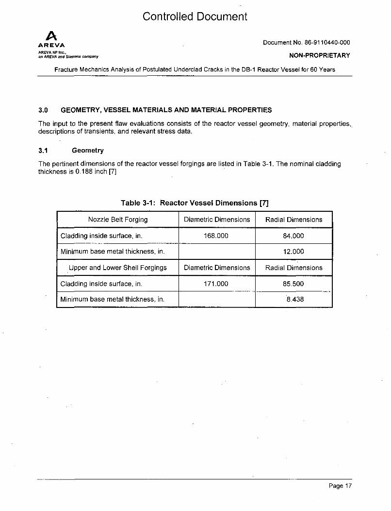
The pertinent dimensions of the reactor vessel forgings are listed in Table 3-1. The nominal claddingthickness is 0.188 inch [7]
Table 3-1: Reactor Vessel Dimensions [7]
Nozzle Belt Forging Diametric Dimensions Radial Dimensions
Cladding inside surface, in. 168.000 84.000
Minimum base metal thickness, in. 12.000
Upper and Lower Shell Forgings Diametric Dimensions Radial Dimensions
Cladding inside surface, in. 171.000 85.500
Minimum base metal thickness, in. 8.438
Page 17

Controlled Document
AAREVAAREVA NP Inc.,an AREVA and Siemens company
Document No. 86-9110440-000
NON-PROPRIETARY
Fracture Mechanics Analysis of Postulated Underclad Cracks in the DB-1 Reactor Vessel for 60 Years
3.2 Thermal and Mechanical Properties
The DB-1 reactor vessel forgings for the nozzle belt (Part No. 169), upper shell (Part No. 170), lowershell (Part No. 171), and the lower head (Dutchman forging - Part No. 181) are fabricated from SA-508Class 21 material of nominal composition 3/4Ni- 1/2Mo- 1/3Cr-V. The austenitic cladding is assumed to be18Cr-8Ni stainless steel material. The PCRIT computer code only accepts constant temperaturethermal properties for calculating temperatures, but does admit temperature dependent mechanicalproperties for calculating stresses. Thermal and mechanical properties for the base metal and claddingmaterials were obtained from Reference [9].
3.3 Nil-Ductility Reference Temperature
The reference temperature index for the nil-ductility transition region of the fracture toughness curves,RTNDT, is a function of the fast neutron fluence and the chemical composition of the material. Values ofRTNDT are obtained from a recent determination of pressurized thermal shock temperatures for the DB-1 reactor vessel at projected fluence values for 52 EFPY of operation over 60 calendar years [10]. Thelimiting values of fluence and reference temperature are listed in Table 3-2 for the four regions ofinterest for underclad cracking. The unirradiated value of 60°F [11] is used for the referencetemperature of the reactor vessel flange since the fluence at this location would be lower than the valueof 2.57E+16 n/cm 2 at the top of the inlet nozzle forging [12]. This fluence value is less than thethreshold value of 1.OE+17 n/cm2, below which a material surveillance program is not required tomonitor changes to fracture toughness due to exposure to neutron irradiation [13].
Table 3-2: Reference Temperatures at 52 EFPY
Forging Material Location Inside Surface Fluence* RTNDT
RV Flange At Weld to NozzleBelt <2.57E+16 n/cm2 60.0 0F
Nozzle Belt At Weld WF-232 2.27E+18 n/cm 2 81.2 OF(Upper)
Lower Shell At Weld WF-182-1 1.68E+19 n/cm 2 95.7 OF
Dutchman At Weld WF-232 2.28E+17 n/cm 2 80.8 OF(Lower)
*at the inside surface of the base metal material.
The current ASME Code designation for this material is SA-508 Grade 2 Class 1.
Page 18
Controlled Document
AAREVAAREVA NP Inc.,an AREVA and Siemens company
Document No. 86-9110440-000
NON-PROPRIETARY
Fracture Mechanics Analysis of Postulated Underclad Cracks in the DB-1 Reactor Vessel for 60 Years
3.4 Transients
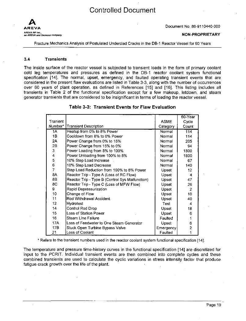
The inside surface of the reactor vessel is subjected to transient loads in the form of primary coolantcold leg temperatures and pressures as defined in the DB-1 reactor coolant system functionalspecification [14]. The normal, upset, emergency, and faulted operating transient events that areconsidered in the present flaw evaluations are listed in Table 3-3, along with the number of occurrencesover 60 years of plant operation, as defined in References [15] and [16]. This listing includes alltransients in Table 2 of the functional specification except for a few makeup, letdown, and steamgenerator transients that are considered to be insignificant in terms of loading the reactor vessel.
Table 3-3: Transient Events for Flaw Evaluation
60-YearTranient ASME CycleNumber* Transient Description Category Count
1A Heatup from 0% to 8% Power Normal 1141B Cooldown from 8% to 0% Power Normal 1142A Power Change from 0% to 15% Normal 2052B Power Change from 15% to 0% Normal 943 Power Loading from 8% to 100% Normal 18004 Power Unloading from 100% to 8% Normal 18005 10% Step Load Increase Normal 676 10% Step Load Decrease Normal 1407 Step Load Reduction from 100% to 8% Power Upset 128A Reactor Trip - Type A (Loss of RC Flow) Upset 48B Reactor Trip - Type B (Control Sys Malfunction) Upset 478C Reactor Trip - Type C (Loss of MFW Flow) Upset 269 Rapid Depressurization Upset 210 Change of Flow Upset 1011 Rod Withdrawal Accident Upset 4012 Hydrotest Test 414 Control Rod Drop Upset 1815 Loss of Station Power Upset 616 Steam Line Failure Faulted 117A Loss of Feedwater to One Steam Generator Upset 617B Stuck Open Turbine Bypass Valve Emergency 221 Loss of Coolant Faulted I
* Refers to the transient numbers used in the reactor coolant system functional specification [14].
The temperature and pressure time-history curves in the functional specification [14] are discretized forinput to the PCRIT. Individual transient events are then combined into complete cycles and thesecombined transients are used to calculate the cyclic variations in stress intensity factor that producefatigue crack growth over the life of the plant.
Page 19

Controlled Document
AARE VA Document No. 86-9110440-000AREVA NP Inc.,
an AREVA and Siemens company NON-PROPRIETARY
Fracture Mechanics Analysis of Postulated Underclad Cracks in the DB-1 Reactor Vessel for 60 Years
3.5 Stresses
The stress intensity factor solution described in Section 2.2 for the postulated inside surface flawrequires that stresses be defined in the reactor vessel wall in order to develop polynomial stressdistributions in the through-wall direction. The required stress profiles can be either first or third-order inthe radial distance from the inside surface, depending on the source of stress. The various loadingsthat are considered for an evaluation of underclad cracking are transient stresses from internalpressures and reactor coolant temperatures, stresses from external loads on the vessel and nozzles,and discontinuity stresses (or adjustments to calculated stresses to account for local geometricdiscontinuities).
Several locations within the reactor vessel are considered for evaluation, as indicated in Figure 3-1.The nozzle belt location at the reactor vessel flange is selected since stresses would be expected to behigh since the thick flange forging serves as a stress riser for stresses in the thinner nozzle belt.Similarly, the nozzle belt is evaluated at the transition from the thinner shell forging thickness (8.438") tothe thicker nozzle belt thickness (12"). Although remote from any structural discontinuity, the lower shellforging will be evaluated at the mid-beltline elevation due to a high value of fast neutron fluence at thislocation. An earlier fracture mechanics analysis of potential underclad cracking in skirt-supportedreactor vessels, performed in 1996 for several B&W-designed reactor vessels [17], showed that thelower shell at the weld to the support skirt was not a controlling location. Since stresses would be lowerin the DB-1 nozzle-supported vessel at a comparable location, and the fluence level is lower at theDutchman forging than at the mid-beltline elevation, the Dutchman forging location shown in Figure 3-1need not be evaluated in the present fracture mechanics analysis.
Stresses are determined at each reactor vessel location identified where a flaw evaluation is to beperformed to address the potential for underclad cracking; i.e., under the reactor vessel flange, at thetransition in thickness, and at the mid-beltline elevation. The basic stress data is obtained from thePCRIT analysis for the transient conditions defined in Section 3.4. The remaining vessel and nozzlestresses, which are only available for selected operating conditions, are then scaled by the governingtransient data and combined with the detailed stresses obtained from PCRIT.
Page 20

Controlled Document
AAR EVAAREVA NP Inc.,an AREVA and Siemens company
Document No. 86-9110440-000
NON-PROPRIETARY
Fracture Mechanics Analysis of Postulated Underclad Cracks in the DB-1 Reactor Vessel for 60 Years
-Nozzle Belt at RV Flange I Evaluation Point 3
- Nozzle Belt at Transition I EvaluationPoint
Lower Shell Forging at Weld WF-1 82-1 Evaluation Point 1
Dutchman Forging at Weld WF-232 (Lower)
Figure 3-1: Reactor Vessel Locations
Page 21

Controlled DocumentA
AREVA Document No. 86-9110440-000AREVA NP Inc.,an AREVA and Siemens company NON-PROPRIETARY
Fracture Mechanics Analysis of Postulated Underclad Cracks in the DB-1 Reactor Vessel for 60 Years
3.5.1 Stresses for Operating Transients
PCRIT transient thermal and stress analysis is performed for each transient combination. Input toPCRIT computer code consists of the data presented in Sections 3.1 through 3.4, as well as theconvective heat transfer film coefficients developed for the beltline shell and nozzle belt forgings,respectively. In addition to calculating temperatures and stresses at selected times during the transient,PCRIT computes stress intensity factors at pre-determined flaw depths in the vessel wall, ranging from1/40th to 32/ 4 0 th of the wall thickness. Critical time points during a transient are selected by reviewing thePCRIT output to determine the times when the maximum and minimum stress intensity factors occur ata representative flaw depth, say 2/4 0 th of the wall thickness (or 2/4 0t). This flaw depth will generally boundthe actual flaw depth after fatigue crack growth. Once the critical transient time points are selected, thecorresponding transient stresses are extracted from the transient results and used to compute stressintensity factors at each calculated increment of fatigue crack growth, as determined from the fatiguecrack growth model described in Section 2.4. The required thermal stresses are extracted fromsupplemental PCRIT results files in the form of the Ai stress coefficients defined in Section 2.2 forcalculating KIT.
Transient pressure stresses are expressed in terms of the Bi unit stress coefficients defined in Section2.2 for calculating Kip. Pressure stresses have been determined for each evaluation point identified inFigure 3-1 from a generic axisymmetric finite element analysis of B&W-designed reactor vessels [18].
3.5.2 Discontinuity Factors
The thermal stresses calculated by the PCRIT computer code are only applicable to cylindrical shellsections remote from structural discontinuities. However, the same finite element stress analysis usedto derive stress coefficients for the closure flange preload and a unit pressure load can be used todevelop scale factors, or discontinuity factors, to account for the presence of stress risers in the reactorvessel wall on thermal stresses calculated by PCRIT. In addition, pressure stresses from theaxisymmetric finite element analysis can be used to develop discontinuity factors for the linear gradientstresses introduced in Section 2.2. An example of a linear gradient stress is the inside surface stresscalculated from a vessel beam model.
While PCRIT thermal stresses are computed for all analyzed transients for remote shell locations,detailed finite element stresses are only available at structural discontinuities for preload, heatup,steady state, and cooldown conditions. The logic for developing thermal discontinuity factors is toconsider that at any time during a thermal transient, the relative magnitude and shape of the thermalstress profiles at the structural discontinuity and the remote location remain nearly constant. Ratios ofthe four Ai thermal stress coefficients, defined in Section 2.2, between the two locations would then besimilar for any "heating type" transient, and likewise for any "cooling type" transient. These ratios, orthermal gradient discontinuity factors, can then be developed for representative heating and coolingtransients, such as reactor heatup and cooldown, where thermal stresses are available. Accordingly,discontinuity factors are calculated at 5 hours into reactor heatup (at the end of the heatup ramp) and at8 hours into reactor cooldown (at the end of the cooldown ramp). By classifying each thermal transientanalyzed by PCRIT as being either a heating or cooling type transient (at the time points chosen forevaluation), the appropriate thermal gradient discontinuity factor can be selected for use in adjustingthe Ai thermal stress coefficients from PCRIT. These adjusted stress coefficients may then be used tocalculate the thermal stress intensity factor at the structural discontinuity.
Page 22

Controlled Document
AR EVA Document No. 86-9110440-000AREVA NP Inc.,an AREVA and Siemens company NON-PROPRIETARY
Fracture Mechanics Analysis of Postulated Underclad Cracks in the DB-1 Reactor Vessel for 60 Years
Discontinuity factors are developed for linear gradient stresses at the inside and outside surfaces usingfinite element stress results for steady state conditions, expressed in terms of pressure stresses. Sincesurface stresses are not available from the finite element results, nonlinear extrapolation is used toobtain the desired stresses. A linear gradient stress discontinuity factor is simply the ratio of the insideor outside surface pressure stress at a structural discontinuity to the comparable stress at a remotelocation in the vessel.
3.5.3 Stresses from Vessel Loads
General reactor vessel shell stresses have been developed [19] for deadweight (DW), thermalexpansion (TH), operating basis earthquake (OBE), safe shutdown earthquake (SSE), and loss ofcoolant accident (LOCA) loads from an isolated beam model of the reactor vessel and service supportstructure. These stresses, which are provided at several locations within the reactor vessel, as shownin Figure 3-2, were calculated at the inside and outside surfaces of the vessel for four conservativecombinations of individual load cases,
1. (DW+TH) + OBE2. OBE3. (DW+TH) + [ (SSE)2
+ (LOCA) 2 ]1/2
4. [ (SSE)2 + (LOCA) 2
]1/2
according to the relationships,
Longitudinal Stress = Axial Force / Area of Shell + Bending Moment x Radius I Moment of InertiaCircumferential Stress = Longitudinal Stress x Poisson's Ratio
In order to mitigate conservatism in the present fracture mechanics analysis for underclad cracking, andto obtain the individual load case stresses needed for the fatigue crack growth and final flaw evaluationphases of the analysis, stresses are derived in this section for individual loads using the generalmethodology provided in the reactor vessel stress input document [19]. Stresses are calculated for flawevaluation points 1, 2, and 3, respectively, using scale factors described in Section 3.5.2 to adjust forstructural discontinuities, as applicable. The correlation between flaw evaluation points and locations inthe vessel beam model is presented below.
Flaw VesselEvaluation Description Model
Point Location
1 Shell Forging at Mid-Beltline 6
2 Nozzle Belt at Transition 4
3 Nozzle Belt at RV Flange 2
Page 23

Controlled Document
AAR EVA Document No. 86-9110440-000
AREVA NP Inc.,an AREVA and Siemens company NON-PROPRIETARY
Fracture Mechanics Analysis of Postulated Underclad Cracks in the DB-1 Reactor Vessel for 60 Years
Figure 3-2: Reactor Vessel Locations for General Shell Stresses
Page 24

Controlled DocumentA
AR EVA Document No. 86-9110440-000
AREVA NP Inc.,an AREVA and Siemens company NON-PROPRIETARY
Fracture Mechanics Analysis of Postulated Underclad Cracks in the DB-1 Reactor Vessel for 60 Years
3.5.4 Stresses from Nozzle Loads
The reactor vessel stress input document [19] provides stresses in the vessel shell from external pipingloads acting on the reactor vessel inlet and outlet nozzles. Inside and outside surface stresses werecalculated at the locations shown in Figure 3-2 for four conservative combinations of individual loadcases,
1. (DW+TH) + OBE2. OBE3. (DW+TH) + [ (SSE)2 + (LOCA) 2 ]11/2
4. [ (SSE)2 + (LOCA) 2 ]1/2
Stresses are calculated from nozzle loads in a two step process. First, surface stresses are calculatedat the base of the nozzle using the Bijlaard method as documented in Welding Research CouncilBulletin 107 [20]. These stresses are then attenuated to other locations in the vessel by treating thesection of the vessel wall between the center of the nozzle and the point of interest as a semi-infinitebeam on an elastic foundation.
In order to reduce conservatisms inherent in the reactor vessel stress input document [19] and togenerate individual load case stresses for use in the fracture mechanics analysis, stresses in thereactor vessel shell are calculated in for individual loads using the general methodology provided inReference [19].
3.5.5 Nozzle Interaction Stresses
The nozzle interaction stresses are discontinuity stresses in the reactor vessel shell at the outletnozzle-to-shell juncture. These stresses, which are the difference between the actual stresses at thestructural discontinuity and the stresses in a remote region of the nozzle belt shell, are available fromthe fracture mechanics input document [19] for several loading conditions. Nozzle interaction stressesare attenuated to other locations in the reactor vessel in the same manner as the stresses at the baseof the nozzle (Bijlaard stresses) that were calculated in Section 3.5.4 from external nozzle loads.
First introduced in 3.5.2 to adjust thermal gradient stresses calculated at remote locations for use atstructural discontinuities, reference heating and cooling load cases are selected from the documentedloading conditions for use in determining nozzle interaction stresses for other transient conditions.Stresses at the end of the reactor heatup to 100% power are used for reference "heating type" transientstresses, while stresses at the end of the cooldown ramp are selected for use as the reference "coolingtype" transient stresses.
The reference nozzle interaction stress coefficients for heating and cooling transients are calculated forlocations where flaw evaluations will be performed, using the appropriate surface stress discontinuityfactors.
The local reference nozzle interaction stress coefficients are used to calculate nozzle interaction stressintensity factors for a particular thermal transient by first calculating a set of linear gradient stresscoefficients to characterize the through-wall thermal stress profile. The reference nozzle interactionstress coefficients at a particular location will then be multiplied by the ratio of transient thermal stresscoefficients to similar thermal stress coefficients derived for the reference heating or cooling thermal
Page 25

Controlled Document
AAREVAAREVA NP Inc.,an AREVA and Siemens company
Document No. 86-9110440-000
NON-PROPRIETARY
Fracture Mechanics Analysis of Postulated Underclad Cracks in the DB-1 Reactor Vessel for 60 Years
stress profile, as applicable. Thermal stress coefficients are obtained from PCRIT thermal stress resultsin the same spreadsheets used to calculate Kiclad.
Page 26

Controlled DocumentA
AR VA Document No. 86-9110440-000AREVA NP Inc.,an AREVA and Siemens company NON-PROPRIETARY
Fracture Mechanics Analysis of Postulated Underclad Cracks in the DB-1 Reactor Vessel for 60 Years
4.0 SUMMARY OF RESULTS AND CONCLUSIONS
Fracture mechanics analysis has been used to perform crack growth and flaw tolerance analyses toevaluate conservatively postulated 6:1 semi-elliptical underclad flaws extending 0.165 inches into thelow alloy steel forging materials of the reactor vessel for normal, upset, emergency, and faulted designconditions. The total initial flaw depth, including cladding, was 0.353 inch, corresponding to a length of2.12 inches along the inside surface of the cladding for the postulated 6:1 flaw aspect ratio. Based on acombination of stress levels and predicted values of fast neutron fluence at 52 EPFY, flaw evaluationswere performed at three locations in the reactor vessel; the lower shell forging at the mid-beltlineelevation, the nozzle belt at the change in thickness, and the nozzle belt at the reactor vessel flange.The reactor vessel closure head was not included in the flaw evaluations for underclad cracking since aone-piece SA-508 Class 3 replacement head is planned to be in place by 2014, prior to the period ofextended operation under license renewal, which begins on April 22, 2017.
Furthermore, since the present fracture mechanics analysis for underclad cracking is intended tosupport licensing activities for plant operation beyond 2017, and the present reactor vessel closurehead is scheduled to be replaced in 2014 with a one-piece SA-508 Class 3 forged head, the closurehead region need not be considered further in the context of the present flaw evaluations for undercladcracking
4.1 Summary of Results [7]
The final fracture toughness margin for a postulated axial flaw in the beltline region is 4.88 for normaland upset conditions and 2.59 for emergency and faulted conditions.
A postulated axial flaw at the transition region of the nozzle belt would produce margins of 3.67 forupset conditions and 1.43 for emergency and faulted conditions. For a circumferential flaw at thislocation, these margins are 4.39 for upset conditions and 1.78 for emergency and faulted conditions.
At the reactor vessel flange region of the nozzle belt, an axial flaw would result in fracture toughnessmargins of 4.36 for upset conditions and 1.75 for emergency and faulted conditions. A circumferentialflaw at this location would produce margins of 7.40 for upset conditions and 2.94 for emergency andfaulted conditions.
These results show that fracture toughness margins are higher for flaws oriented in a circumferentialplane. Table 4-1 summarizes the results of underclad cracking flaw evaluations for postulated flaws inthe controlling axial orientation.
4.2 Conclusions
The results presented in Table 4-1 demonstrate that the potential for underclad cracking in the DB-1reactor vessel are within the acceptable margins of the ASME Code for fracture toughness of thesusceptible SA-508 Class 2 forging material for the period of extended operation. For an axiallyoriented flaw, the limiting -normal and upset condition fracture toughness margin is 3.67, which isgreater than the value of 3.16 required by Section X1, Article IWB-3612 [2]. Likewise, the calculatedmargin for emergency and faulted conditions of 1.43 is greater than the minimum value of 1.41 required
Page 27

Controlled Document
AAREVAAREVA NP Inc.,an AREVA and Siemens company
Document No. 86-9110440-000
NON-PROPRIETARY
Fracture Mechanics Analysis of Postulated Underclad Cracks in the DB-1 Reactor Vessel for 60 Years
by the Code. It has also been demonstrated by analysis that the fracture toughness margins calculatedfor circumferentially oriented flaws are consistently higher than those for axial flaws.
It is further noted that the size of the postulated underclad cracks considered in the flaw evaluations areat least as large as the 0.165 inch deep by 0.500 inch long subsurface crack mentioned in RegulatoryGuide 1.43 [3] as the maximum extent of underclad cracking that has been observed in the industry.
Therefore, the postulated underclad cracks in the DB-1 reactor vessel are acceptable for continuedsafe operation through the period of extended operation.
Table 4-1: Summary of Results
Initial Flaw Depth = 0.353 inch
Location in Final flaw Loading Controlling Calculated RequiredReactor Vessel depth, af Condition (1) KI(af) (2) Fracture Fracture
Toughness Toughness(inches) (ksiqin) Margin Margin
Shell Forging N/U 41.01 4.88 /10and Mid-Beltline 0.380
Elevation ElF 77.31 2.59 /2
Nozzle Belt at N/U 54.44 3.67 •/10Thickness 0.396Transition ElF 139.6 1.43 /2
Nozzle Belt at N/U 45.88 4.36 /10Reactor Vessel 0.390
Flange ElF 114.4 1.75 N12
Notes: (1) N/U = Normal and upset conditionsE/F = Emergency and faulted conditions
(2) Controlling stress intensity factor occurs at the final flaw depth for an axiallyoriented flaw
Page 28

Controlled DocumentA
AR VA Document No. 86-91 10440-000AREVA NP Inc.,an AREVA and Siemens company NON-PROPRIETARY
Fracture Mechanics Analysis of Postulated Underclad Cracks in the DB-1 Reactor Vessel for 60 Years
5.0 REFERENCES
1. BAW-1001 3-A, Study of Intergranular Separations in Low-Alloy Steel Heat-Affected ZonesUnder Austenitic Stainless Steel Weld Cladding," October 1972.
2. ASME Boiler and Pressure Vessel Code, Section XI, Rules for Inservice Inspection of NuclearPower Plant Components, 1995 Edition with Addenda through 1996.
3. U.S. Atomic Energy Commission Regulatory Guide 1.43, "Control of Stainless Steel WeldCladding of Low-Alloy Steel Components," May 1973.
4. ANSYS Finite Element Computer Code, Version 10.0, ANSYS Inc., Canonsburg, PA.
5. AREVA NP Document 32-1174278-007, "Verification of PCRIT 6.3 & User's Manual," May2010.
6. I.S. Raju and J.C. Newman, Jr., "Stress-Intensity Factors for Internal and External SurfaceCracks in Cylindrical Vessels," Journal of Pressure Vessel Technology, American Society ofMechanical Engineers, Vol. 104, pp 293-298, November 1982.
7. AREVA NP Document 32-9110439-000, "DB-1 FM Analysis for 60 Years," June 2010.
8. S.P. Timoshenko and J.N. Goodier, Theory of Elasticity, Third Edition, McGraw-Hill Book Co.,New York..
9. ASME Boiler and Pressure Vessel Code, Section II-Materials, Part D - Properties, 1995 Editionwith Addenda though 1996.
10. AREVA NP Document 32-9123247-000, "RTPTS Values of Davis-Besse Unit 1 for 52 EFPY,Including Extended Beltline," November 2009.
11. BAW-1 0046A, Rev. 2, "Methods of Compliance with Fracture Toughness and OperationalRequirements of 10 CFR 50, Appendix G," B&W Owners Group Materials Committee TopicalReport, June 1986.
12. AREVA NP Document 86-9025792-001, 'Davis Besse Fluence Analysis - Cycles 13-14Summary Report," October 2009.
13. U.S. Code of Federal Regulations, Title 10, "Domestic Licensing of Protection and UtilizationFacilities," Appendix H to Part 50, "Reactor Vessel Material Surveillance ProgramRequirements," Federal Register, April 12, 2010.
14. AREVA NP Document 18-1149327-003, "Functional Specification for Reactor Coolant Systemfor Davis-Besse," July 2008.
Page 29

Controlled DocumentA
AR VA Document No. 86-9110440-000
AREVA NP Inc.,an AREVA and Siemens company NON-PROPRIETARY
Fracture Mechanics Analysis of Postulated Underclad Cracks in the DB-1 Reactor Vessel for 60 Years
15. AREVA NP Document 38-9121554-000, "Davis-Besse 60-Year Projected Transient Cycles,"September 2009.
16. AREVA NP Document 38-9128551-000, "Additional Transient Cycle Data Applicable to theDavis-Besse Pressurizer Surge Line," December 2009.
17. AREVA NP Document 32-1245893-00, "FM Analysis of Postulated Underclad Cracks in B&WDesigned RV for 48 EFPY," July 1996.
18. AREVA NP Document 32-1128225-00, "Stress Analysis of Reactor Vessel for L.E.F.M. Use,"October 1981.
19. AREVA NP Document 32-9120525-000, "Davis Besse Unit 1 Reactor Vessel Stress Input forFracture Mechanics Analysis," February 2010.
20. Welding Research Council Bulletin 107, "Local Stresses in Spherical and Cylindrical Shells Dueto External Loadings", by K.R. Wichman, A.G. Hopper, and J.L. Mershon, August 1965, WeldingResearch Council, Inc., New York, NY.
Page 30

Enclosure C
Davis-Besse Nuclear Power Station (DBNPS), Unit No. I
Letter L-11-107
Centerior Energy Letter, "High Pressure Iniection/Makeup Nozzle and ThermalSleeve Program Davis-Besse Nuclear Power Station Unit I (Serial No. 1968)."
(ADAMS Accession Number ML9109030090), August 23, 1991
4 pages
not including cover sheet

CENTERIORENERGY
Dondl C. Shelton 300.Madism AvenueVice PuWsent. Nudar Toledo, OH 43652-0001DavI&s •(419) 2492300
Docket Number 50-346
License Number NPF-3
Serial Number 1968
August 23, 1991
United States Nuclear Regulatory CommissionDocument Control DeskWashington, D. C. 20555
Subject: High Pressure Injection/Makeup Nozzle and Thermal SleeveProgram Davis-Besse Nuclear Power Station Unit 1
Gentlemen:
The purpose of this letter is to inform the Nuclear RegulatoryCommission (NRC) of Toledo Edison's (TE) evaluation of High PressureInjection (HPI) Makeup Nozzle Thermal Sleeve reliability. By letterdated May 3, 1990 (Serial Number 1802), TE summarized the actions takenduring cycle 6 and the sixth refueling outage (6RFO) resulting from thediscovery of the failed HPI/Makeup nozzle thermal sleeve during thefifth refueling outage (5RFO) at the Davis-Besse Nuclear Power Station(DBNPS) Unit 1. The major actions taken through the end of the 6RFOwere focused on the assessment and preservation of the structuralintegrity of the nozzle which had experienced thermal cycling due tothe thermal sleeve failure. Analysis demonstrated that an intactthermal sleeve effectively protects the HPI/Makeup nozzle from theeffects of thermal cycling fatigue. Since the thermal sleeve failurediscovered during the 5RFO was attributed to thermal cycling fatigue,induced by makeup flow cycling, control of makeup flow was improved asdescribed in TE's letters to the NRC dated September 14, 1988 (SerialNumber 1580), May 3, 1990 (Serial Number 1802) and May 25, 1990 (SerialNumber 1808). Recognizing the importance of long term thermal sleevereliability, TE committed to investigate the mechanisms which affectthermal sleeve life, and evaluate alternatives which might be pursuedto ensure long term reliability. Toledo Edison's letter to the NRCdated December 3, 1990 (Serial Number 1871) provided the details ofTE's plans and schedule to address thermal sleeve reliability.
Operating Companies* Cleveland Electrc Illuminating
7oledo Edison

Docket Number 50-346License Number NPF-3Serial Number 1968Page 2
Toledo Edison's plans focused on a fracture mechanics based predictionof thermal sleeve life under various makeup flow cycling conditions.As contingencies, TE planned to investigate the impact of prematurethermal sleeve failure on nozzle structural integrity, and to conduct apreliminary assessment of the feasibility of on-line monitoring forthermal sleeve presence. The favorable results of thefracture mechanics thermal sleeve lifetime prediction has obviated theneed for further consideration of the impact of premature thermalsleeve failure and on-line monitoring for thermal sleeve presence. Thefracture mechanics analysis predicts a lifetime exceeding 20eighteen-month operating cycles in makeup service under current makeupflow control conditions. Cycle 7 is the first operating cycle inmakeup service for the current HPI/makeup nozzle thermal-sleeve.
Babcock and Wilcox Nuclear Services (BWNS) and Structural IntegrityAssociates (SIA) performed the evaluation of thermal sleeve reliabilityfor TE. Babcock and Wilcox Nuclear *Services, using the proprietaryBWNS FLOIJTRAN computer code, provided fluid temperature distributionscorresponding to the actual range of makeup flow rates. SIA used thisinformation to develop stress distributions within the thermal sleevefor the range of makeup flow rates using the ANSYS computer code:These results were used as input to a fracture mechanics analysis ofthe thermal sleeve in conjunction with makeup flow cycling conditionsdetermined from actual recorded operating data. SIA's pc-CRACKcomputer code was used for the fracture mechanics analysis.
Recorded makeup flow data for several representative days in fuelcycles 5, 6 and 7 were analyzed to establish the makeup flow cyclingconditions used in the fracture mechanics analysis. The data includednormal power operation days during all three fuel cycles as well assome off-normal events such as trips and shutdowns.
The fracture mechanics model used to analyze the sleeve was chosen tobe representative of the fracture behavior of the sleeve observed frommetallurgical analysis of the broken sleeve pieces recovered from thereactor vessel during the 5RFO. A fracture mechanics model for anaxial, semi-elliptical surface flaw of varying aspect ratio, in acylinder, was selected from the pc-CRACK fracture mechanics modellibrary. This model is consistent with the findings of themetallurgical analysis that fracture initiated predominantly on theinside surface of the sleeve, at or near the outlet end of the sleeve,and that the primary flaw propagation direction observed was outwardfrom the inside surface with the flaw oriented axially on the thermalsleeve, indicating that axial extension in length was a consequence ofthe changing aspect ratio of the semi-elliptical flaw once itpropagated through-wall. For this analysis, the pc-CRACK model wasadjusted to calculate the stress intensity factor at the inside surfaceof the thermal sleeve. The stress intensity factor at this location ismore important to flaw propagation in the axial direction than thestress intensity factor at the deepest point of flaw penetration, whichis normally calculated by pc-CRACK.

Docket Number 50-346License Number NPF-3Serial Number 1968Page 3
The stress intensity factor was calculated by pc-CRACK using this modeland the ANSYS thermal sleeve stress distributions for the range of makeupflow rates. These pc-CRACK stress intensity factor results and theAmerican Society of Mechanical Engineers (ASME) Boiler and PressureVessel Code, Section XI fatigue crack growth correlation for stainlesssteel were then used to predict flaw growth under the various makeupcycling conditions.
Using this approach, the calculated flaw growth rate for the makeup flowcycling conditions which were prevalent prior to the 5RFO comparesfavorably with the metallurgical analysis of the failed thermal sleeve.The fracture mechanics anplysis yields predicted flaw growth rates on theorder of 2.5 to 3.5 x 10- inches per makeup flow cycle.- Themetallurgical analysis reported striation spacing of less than one micronwhiSh corresponds to an approximate crack growth rate of less than 3.9 x10- inches per stress cycle. Therefore, the fracture mechanics modelpredictions correlate well with the observed thermal sleeve failure.
Under the makeup flow cycling conditions which were prevalent prior tothe 5RFO, the fracture mechanics analysis predicts that an initiated flawwould propagate sufficiently to result in thermal sleeve failure-inapproximately eighteen months of operation. Since the thermal sleevefailure occurred about halfway through fuel cycle 5, approximately thefirst three fuel cycles were required to initiate the flaw under thesevere makeup flow cycling conditions which dominated that period ofoperation.
After the thermal sleeve failure was discovered during the 5RFO, makeupflow control was improved to reduce both the frequency and amplitude ofmakeup flow cycling. Under the improved makeup flow cycling conditionstypical for fuel cycles 6 and 7, the fracture mechanics analysis predictsa thermal sleeve life exceeding 20 eighteen-month fuel cycles. Thisprediction is based on a larger assumed initial flaw size because withthe improved makeup flow control conditions, a much larger initial flawsize must be assumed for any significant flaw propagation to occur.
Considering that approximately three fuel cycles were required toinitiate a flaw that would propagate under the severe makeup flow cyclingconditions which existed prior to the 5RFO, it is reasonable to concludethat at least as long a period will be required to initiate a flaw whichwould propagate under the current improved makeup flow controlconditions. The time required for flaw initiation provides addedconservatism to the predicted thermal sleeve lifetime of 20 fuel cycles.
The thermal sleeve currently in makeup service was installed in the 5RFO,but has only one fuel cycle of makeup service. The makeup flow path wasre-routed to the current nozzle during the 6RFO as one of the actions inresponse to the discovery of the failed thermal sleeve during the 5RFO.With the current improved makeup flow cycling conditions, TE plans nofurther actions to address HPI/Makeup nozzle thermal sleeve reliabilityand considers the matter to be closed.
Docket Number 50-346License Number NPF-3Serial Number 1968Page 4
If you have any questions regarding the information provided by thisletter, please call Mr. R. W. Schrauder, Manager - Nuclear Licensing at(419) 249-2366.
Very truly yours,
cc: P. M. Byron, NRC Region III, DB-1 Senior Resident InspectorA. B. Davis, Regional Administrator, NRC Region IIIJ. B. Hopkins, NRC/NRR DB-1 Senior Project ManagerUtility Radiological Safety Board
Enclosure D
Davis-Besse Nuclear Power Station (DBNPS), Unit No. 1
Letter L-11-107
Babcock and Wilcox document 32-1172294-00,"Davis Besse 1 SG Flaw Evaluation," dated 6/9/1988
Babcock and Wilcox document 32-1172294-01,"Davis Besse 1 SG Flaw Evaluation," dated 7/18/1988
Babcock and Wilcox document 32-1172523-00,"DB-1 SG Flaw Evaluation," dated 7/18/1988
38 pages
not including cover sheet
(12 pages, 4 pages, 22 pages)

- SNP 2069 16,M)
ftbcock &L Wflcoza M~c).rmalt company
I
DOCUMENT SUMMARY SHEET !DOCUME ENTI'~tPIE 3JZ LUv29!L- CDý'
TT L.....Ed u _-A
PREPARED BY: REVIEWED. BY:
HAMLA~ ~M C~L NAML~~ -
SIONATU RF . ..... . .. . _qNATU__ -- ___
OTIE C R."- -1TM STATEMENT:
COST cE'ERJ. .L .REV PAGE(S)!" REVIEWER INDEPENDENCE -- -- - i n! i, - - . im m m~l lwl -i
PURPOSE AND SUMMARY OF RESULTS:
The purpoae of this calcu•ation is to evailuite Davis basso Stealm Generatorflaw indLcations aocording t.) the ASME code pr•cadure.
-... . ..... -.. . ...... ... . .. ..... .. . .. . .o
The flaw indicatLo, found- to be Aoap;•Able by the AGK-S SootLon XZ, ZiJW.3612standA-d,
THE FOLLOWING COMPUTER CODES HAVE BFEN USEr) IN THIS DOCUMENT:EOD /VERSION /REV CODE /VERSION /REV
V
I.PAGE .O 2 ..

Pmuchar Pt*.v DIMISrn
GENERAL CALCULATIONIS,32-1172294-00
. - E(~IaQr1~IQN - -
ft..a - -- *a..~ e.~b* n a* tfl. h~ 0.&Jxvým&m" - "mmu& M& w" K a x
00 original Release S6/88 -.
K. K. YoonPRIPARID NY
NuIS11WD by
I~IZ DATEDATE P01 NO,
?

,aK*A awMX CAENERAL CALCULATIONSN uclear Pow er Divislon Doc, I,' . .... ..........
Davis Sense I Steam UClewato: flaw 3y'eluation -.. .
1.0 INTRODUCTION
DurinA May 1988 nipoe tlon, thare were a number of flaw indications.detacted
in the steam generator shell near the steam outlet nesule (Ref, I and 2).
It was found that only ýtoindieatinor were needed for evaluation
(Indcaton.000 and. #01)__, Theremaining indication. are bound.d by these
two,
Using the atranmeas iro RaeS, theoe M tndications were evaluated
acoording to the ASHI Boiler and Pressure Vessel Code, Section XI (Ref.5),
.... . .-... *
PRPARD 1Y 00A04 AT
REVIEWD .y OAT[. PAOE NO,
Muabca4 Maw GENERAL CALCULATIONS.* MoOefiwm CO0PflV
NuchBar Power DIvivion DOC, I,.'5 " I"t¶A4 -OO.
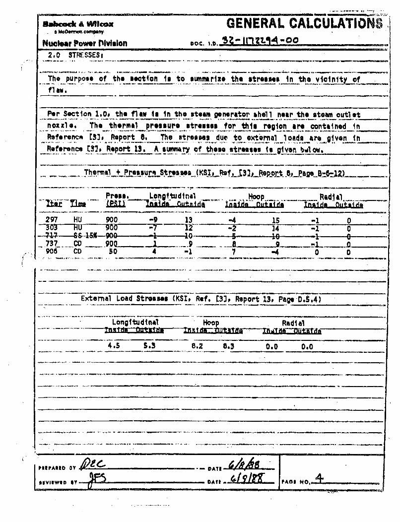
2,0 STRESSES _
.T.h pupose of the section Is to s.ummrlz, the stres em In the vi'init, offl aw.
Per Section 1.0# the flaw Is in the steam generator hhell near the steam outlet
.. The_.thern~ressure stresses for thtlu repion are contained tnReferencm Ma). Report 8. The stresses due to external1 loads a r given inReference Ms~ Reoport 13. Asiwryof these stresses is given b'low.
Therml + Pressurs Stresses (KS .,_Rs 3_R.ep1ot.._.g..u-JZ) -
Pressa. Longitudinal+lc:p....Rd~
297 HU 900. -9 13 -4 15 -1 03,'O3Ju 9o0 -,7 -2 -1 07P & 90--'----- 0 --- t - 5 io - 0 -.737.... CO _ -900. .-. 9 .- A906 CD so 4 MI 7 -4 0 0
External Load Strsses (KS!, Ref. [33P Report 13, Page-D.5.4)
Longitudinal Hoop Radial
4.S 5.3 .8.2 83 0.0 0.0
PRIPARSIi iiYi OoAOI-AT

36Cock A WX GENEPAL CALCULATIONSS McD, m•n~ compw•
Nucear Power Division Doc, I.o.lk. 0 12. "00.2., MAXIMUM TENSILE STRSS.ES
The maximum tensile strosses due to therml + presoure are conserativtelyconbined with the stressn due to .x.o iial loads to obtain the maximum tensilestress in the flaw regi.. The tonsile stresses are summarized below.
Maximum Tensile Stresses (KSIP TH + PR + External Load)
I ngatu44Ml HoopInstde__ Outild Inf4d Ou4tsde • nd ujt d
..............-.-...--. #4-----s,3 ...... 16,2 .... 23,3 ...... -- 0rO'- -'OO--"
2.2 MAXIJM STRESS PMANE:_
The stress range due to themal.+ prssu_re loads Ils conservatlvely__o.n.tnodwith the._external load stre.es. .to obtain the maximum stress rangei,__T.he
__max t~mum__u.tr~.es~J'an•OaI~r., ijumma ri: fzd_,bei.L€.. .. . .
Mo~~l~~luinl Sti +~ Mai i~Il*F RunWV + ernail -Mad)Longitudinal Hoop Radial
17.5 19.3 20.2 27.3 1 0
2.3 PRESSURE VERSES TEDPERAKPRE-
Figure 1.0 of this section shows the pressure and temperature conditlons of the .1OTSG secondary side (shell) during the cooldown transient, This figure istaken from Reference 143. _
PVIPF0.010 NY DATS _.A
lVllNWt3 11Y OAT . . .,A dl FAOI NO,. .. ..5_+

FT-"' 1.0
Transient N~o. IB (Cooldoim from 8% FP) _
Steam Temperature aid-Pressure During Cooldowm from 8%'FP or Reactor Trip A'ý
X-:tie 11 ... -.. . .o.... .. . .C
0Tz
-- -- - -- -- -3:, e c o r p. . .. ... - - -
-~ ------ (t--- .o v .C ....
I d100 LJLL
* 5I Z 4 tsers 0141id late 14 Uea
480 3" WDry~am

4 Oft&. 0 1 A I. 1 nA % "
Babe"* a Me. GENERAL CALCULATIONSa M c~ro, 1 • e 32-1172294-00
Nucler Pow.? D.Molon DOC. 1.1).
3,0 MAW EVALUATION OF INDICATION .1O, I'"D
3,1 STRESS INTEM11TY FACTQM
From Ref. 1, the folloving shall and flaw geometry data are available:. . .. ...... .... ...... ... .. .. .. -s-_ - p _ _,
thickness t - 7.1 in.
flaw location - 1.5 in.,flaw size 2a- 1_0 in.
flaw length A -' 1.0 in,
a/t 0.75/7.10
!
I__________ * 4 4--
It°+.(
eccentricity a = 3,55-1.5-s- 1.3 in,
. Pron.Fig, A-330U...1.. of Re f,, 5j..the aspect ratio.for this flaw war. found to beoutside of he t range of this figure, thereafors,..a conservative value of
_Q-2.2 was jeleoted.
.__..ig._A.ý3300-2 ofRefg.j5y4ildq __
•m - 1,04 for.2*/tm, 0,2113
Prom Section 2.0 of this raport themaxi membrane teu 23._SmZ3J _
will cover all cane.
2EvtIwEo AY
M.F, xoon
SPOIi . .... . .

, ~POS.ilOSG.3 (*4e4)_ _ _ _ _ _ _ _ _ _ _ _ _ _ _ __,_ _ _ _ _ _ _ _ - I : " '" " -lt a t l •a •. J
Bauock t Wilcox GENERAL CALCULATIONSa MtDo.tm-A company 32-1172294-C0
Nuclear Power Divhdori Doc. 1.o...--.5.-
Sinc. " ii -Ms,•. :
-23 x 1.04 (3.14 x0.75/ 2.2)
- 24.7 kal n.
The stree•se are for MU. and CD..
3.2 FATIGUE CRACK ORO='flAMLYSI9 .-..-.
.Snc, there, are 240 heatup and cooldo•wn ycles hiav,, s.ignificaut-:
stresses in the region under consideration, the final crack iizq af will be* calculated by the Appendixi A of Ref. 5 procedure.
..... ..- ; c .• • .. . . . . . . .. .. . . .. . . . .. . . ...The fatigue crack growth rate equation for a subsurface Zl~at' &v -
d/N Co (A~iC)'
where da/dN • growth rate in micro inche./cycleCo -0.0267 x 10'
n -3.726.. KI streas intensity factor range .j_ ,
For a siamplifi.d evaluation, a constant AIS in asaumed and will be ohecIe ..after the final crack a.iLxin determined,. Also MKin_ assumed to be 24 7kai Fn which in .larger than any atress range show.n in Section 2,0.
da/dN - c(; 24,7)n4.128 nicro-in,/eyle..
-4.128 x 10' in. / ycis . -
,a - da/d? * 240- 0.00099 in.
___Since Aa is loss than one-xil,_1 .there in almost-no crack growth. -Therefore,.the ftna•7 crAck sixe Le the saoe as tho initial,.rack asi, and the constant.....
P.IPARIDY~.w.. ----.- y-y-,, O. DATEAIVIEWID mY 7 DATE PAO I NO. I-I

I I .. PDO1103.3 -(90.4)
J.
&a"- aVOICOXGENERAL CALCULATIONSý-com• 32-117229"-00
Nuclear Power Division ,oD. .o. ...
AXI assumption In valid. Finally,
X1. -24.7 kal
3.3 ACCEPTANCE CRITERIA
Figure 1 shown that the operating temperature neve'r cornes down bolcw 280F.•less the pressure drops below 100 psi level from 900 psi. Therefore:, th-
minimum operating tenrep'ature can be set at 280F.
For tho SG shell there in no appreciable fluence ou$,:lation, hence,
RT - iitial RT............ . .....- P (O_ I. af.•)...... . .. _ _ .
.. . . .. . . .. . T . * . -' T , 2 8 O - ..0 _- . 2 2 0 . F.. . . . . . . . .
.From Fig, A-4200-1. of sfL_3.__KI 20_-L2 0.-. . ...
.... ]•a/ ICI.-.200/-2A.._-m.8.± > 3.l6.m•/10- ..........................
. "Therefore, thI.h AflA4aeeaptabhl,-by -IW3•4B.-612.-
K. K. 7O0f.
PROPARED Sy OATS
WiyiiID my DAE__ Q H.S ~-.-.-" - . - -
'P01.21036.3 (p.44) "
&QfaMt GENERAL CALCULATIONSa M Co* nXft COM• a" 12 -1,1 7 2 2 9 4-0 0
Nucd r Power Division uoC. 1.0.
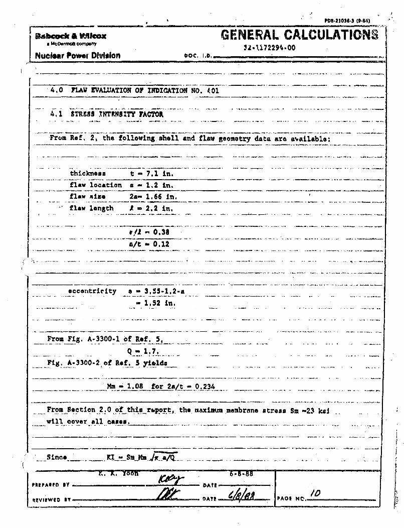
4. 0 FLAW EVALUATION OF INDICATION NO. 401
4.1 STR9S83 NTERKS1Y FACTOR
From Ref. 2, the following.shell and flaw geometry data are &NAilable:
thickness t - 7.1 in.
flaw location a - 1.2 in.
flaw size 2a- 1.66 i.n.
flaw length A - 2.2 in.
a/ '0.38
-a/tm 0.12
eccentricity em 3.505-1.2-a
- 1.52 in.
From Fig. A-3300-1 of Ref. 5,
Fig. A-.3300-2.of Ref._ 5.yield. .....................
Mm- 1.08 for 2a/t- 0.234
From Section 2.0 of this rbporp;, the maximu membrane stress Sm -23 k ... .
will Cover all came,.
t)ATI
__Since~o NY .... m
PU! !AF Y~Ot
'IIeP~wlO IV. .. •DIE • OI l"_ _ _ _ _ _ _ _ _ _ _ _ _ _ _ _ /
•VliWIO |y ..... ATI• PAD N@.. . ..
4 4
PDI.11064• (9.14)
Babcock A WVlcoxa McDrmot!compeny
MJuclear Power Division
GENERAL CALCULATIONS32-1172294-00
. DOC. A DI * Id.
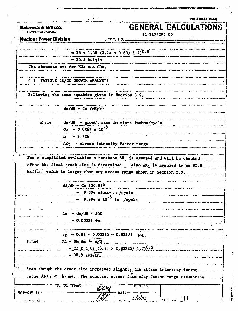
-_23 z1.08(3.14 x 0.63/ 1.7 *
. 30.8 kii, in. ............ ...
The strouses are for HUs sa4 CDs.
4.2 FATIGUE CRACK GROT ANALYSS
Following the -m- e equation given in Section 3.2,
da/dH = Co (AKI )n
where da/dN• .rowth rate in micro inch.s/cycle - .
co 0,0267 x....
n - 3.726
_I - stress intensity factor range
For a &imp ified evnluation a EonstantL A .is assumed and vwil be checked
after the final crack size is determined. AlsoAK i asaumed to be 30.8
k'i r"i which in larger than any stress range shown in Section 2.0,IdA/d.= Co ( 3 0 ,8 )n
-- 9,394 micro-4 .n./cyrcle
.. 9..3.94. x.. . in... /cycle-- - ----.. -4 -..-
As _da/dN 240 .... .......
- 0.00225 in.
af 0..083 t.0,00225 - 0.83225 . . . .........
_Since KI-ft Mm ~__-23 x 1.08 _(3.14_x 0.83225/1 .. 7. 5
....- 30.8 ksi
Even though the crack. suie -ncreased slightly the. stress intensity. f ntor ........
_value did not, change,.__The conetant stressintensityfactor-.-anga- assumption.........
1 PR~~r s.4 I
K. K. 7oon
1,i - - r A I" .... .. ,. " "y .. -

____________PMS21O*8(b0-84) .
... .S: .
i, ,
• j,
McockA Al Mcax GENERAL CALCULATIONSa M eom.. d C• gaf, m'32 -11.72294-00 '
Nuclear Powv.r Ivislen Doc. ,.6. • __-__ _ _ _.
wan valid.
4.3 ACCEPTANCE CRITE•IA
Following the seom procedure described in Section 3.3
T - RT*DT- 280 -60 - 2 2 0 F
From FPL. A-4200-1 of Ref. 5, KI, - 200 kiJ in-.
-. C KI-/ KI - 200/ 30.6 6.49 > 3,16 -. _ _
Therefore, this ilaw in acceptable by IWB-3612.
5.0 CONJCLUSION
The two soele_.•d indicationa are found tn be aocn table IVy_ ;WB.3612 _,_
criteria.
6.0 FERENC•KS-
1. BW& Volumetric _Exmwination Evaluation Rp ort TED 88-026 '!ay 12. 19_8.'2. •W Volumetric Examination Evaluation Rep ort,: TED 88-029, May 21, 1988,3. MW Doc..ument. 'Des£in poqrt," Toledo Edison Company & C.E.I., B•
Contract No. 620-0014-55, RC Microfilm Rpý' g._ -_____ a____8_O1IG,4. MW Documnt 018-1149327-ID "Functional GpecifIoation forR'aotor
Coolant S7yatow. " m1traot No. 582- 751.onC.,_S,.,_.5. ASHE Boilez and Pressure Vessel CodeSectionXI F_..Ed .tL•_'
I.
I

B01, P 20032-15 (7/Uc'i;"• ~I e•s.e 7-,. ~a,,L. FbccNk & Wilcox -,
h ~Isicimlovi ctfnmiwl DOtIUMEr1T RELEA!RE PO"TICE (DRN) I crd MImm/64V kfil. f "" •-NT . .HARUL NO.18o__ PV B iES I J/o I Pa,,-L0•-!-.
3 DIGIT TASK NO.,PART NO., OR
TASK GROUPSEO.B&W DOCUMENT NO, DOCUMENT TITI,[
(30 Chart irs Miximum)
SAFETYCLASS
(OMIT FORNSSIB,16 & 23)
PUI.1WSlAT ATVI(09 KY/N)t(l
9
32-. Ulntq•,4 -.-f, P.BSA ..36 AL.•c T,,AIArjnOk ....... SII-. m~- 4. ~ -. I - -?
I fl I I I I A & I I I B ill I II-'A I - -. ~ 4. - ~.I - ~' --
.i A- | l I I- I I I mlu.| I, I . .• - -
j Li
I I I 1 1 Il II I I I I I II
NO . il lII. NO. I "1•l
- -- - i - II L I •- - I -I '1 -' =
- L.L.• L .L.JJ1LJ.IL._J.~L LL-•1. ,.
kCQUIRED OISTR'BUTION , C•ORMAT I NO, COPIE'M(ORGANIZATION OR TE) DRN DO CM (INDIVIDUAL'S NAME) iRN DOC C
_• _u •• - _ .....- ,..
-, V..• z j .. ..
~.ii •, _) M.,V • / /. __ __,___ _
- 4. - m - 4. - -4- .- ~- 4-4- -
.-:4 .- - - - - 4. - .-.
- - -
* -4-4. -, 4~ d~4. -
9 44. -9 i i S -
-_- . - L --- 4. -4i i-PROJESI NGINEER.'PM APPRO•A /'.
(SiGNATURAT
1Pr1NTED NAMEL27 Z6,0 4 g m tax--
-- I ~9-~ I -
WINJASEO BY (P#PARE•
(/N~NQ
I I_ _ I-
6M7
AR'IIEWED RY:
(MA.T' 0 NAMtJZE) 4- - I

..wNr ,6mp t
ab'Ack & Wilrox1(- *h t*,frtot! €o* ny_
DOCUMENT SUMMARY SHEET II I L• Ill • i I m I I is I I pI.f1
DOCUMENT IDENTIFIER " "Z I. I 7z2,9./ - o /
PREPARED BY: HEVIEWED BY:
NAtLJjJ-- HAME_._ 3-46.A"- .
SSIONATURLU!. SS
TITLENAT .•4 • -.-.. DATE___-_ TITLE _L'•1 S V"T'M STATEMENT:
COST CENTER-..3/Q, .REF, PAGE s.J_/. REVIEWER INDEPENDENCE
PURPOSE AND SUMMARY OF RESULTS:
'he purpone of this calculation in to evaluate Davis Bon*s Steam Oenarator
n1nw 1o)1AtionN according to the ASHfC code pronedure.
The flaw indications found to be acceptAble by the ASML Section XI, 114B.3612
xtandard,
Revision 1: Rpfarenoe 5 was changed to 1977 edition, Instead of 1986.
No oth,"r changes are resulted from thin correction,
THE FOI LOWING COMPUTER CODES HAVE BEEN USED IN THIS DOCUMENT-
Cr" /VTMION R/V m 1 0N Kv
PACTF n nr

~Dt.3IO36S (944)
Babcock A Ww~cam& McD~emttw Conilniy
~NuclearPower Divkision
1
.GENERAL CALCULATIONS'32 -1172294 -0/
DOC, 1. 0,
!C04 = 5F 10~IN
fl~ ~!hnnwaa11 I IU U flAk t-
00
01Original Release
Reference 5.revized. Lve*g 10A
6/20/886/30/88.........
IK.Z K. yXoI*
PRIPAME by-
91IPWIED NY
~1 6/3u/88
DATIPAOF NO.I
!

Aabcock & Wieox GENEARAL CALCULATIONSa hMCOWtMal compef'y 32-1172294 -OfNuclear Power Division DOC. i1o0in
__..3 ACCEPTANCE RTU .......
Volloviztg the same procedure.B described £x..eotLotn .3.3. ..-...... --
.-.-. T Ufft.-280_ý..6Q....u 220 T._........
From Fig. A-4200-1. of Ref.. 5*-.XI& 20g. kni in......... .. .
KIa./.IC. -. 200/ 30.8--. 6.49 > 3.1.6 - ~ -.
-Therefore, this flo im L acceptable by ITh-36l24..'-..-........ ... ....
- 5. 0 CONCLUS ION ... *. ... .. . .......
The two -solooted indications are found to be aeo~ptable by IW -3612
6. 0 REFERMCKS . .-.. .
1~ 34 Valwmetric H Nxaition tvyaluntiont Repoft, E 88-026, haty 12, 1988--2.. S4W Volum.trio Examination Ilyfa uat ion Rport-,- TftD -6629,H-ay-21-98~
- , MM - 8W j)ument, "Des ign~-!fteoft j0 Toletdo--Edison--Coupmny *-&.-0 R -1 0-0 6 ----.- - - CttraeL~-No. 620-00Q1*455 --NPOD, Hicrof ilit Roll c;--0- f p 5f7ndtO-W-
MM84 DooLment 010141*9327-00; "'Fuatioinal spn'ification .for t.- O oolwft Rytu---3etatto 82-7151, Tolvda-Rdivan -a. 4 ~ -
PEEPARID IV,-~- DATE

BWNP 20697 (6-85)
I ~ Babcock & Wilcoxa McDermott companyDOCUMENT SUMMARY SHEET
DOCUMENT IDENTIFIER 3'. 1T 757-1, "bO
TITLE 'E~LNW aAt&,Tt,,j
PREPARED BY:.Dr-a S-ANlaur0M &P
REVIEWED BY:
NAME V7F SWeP'>SIGNATURR. . .
TITLEDATE 40 SINTUR IF PrVSM4A 5J-' l
TM STATEMENT: ..A,REVIEWER INDEPENDENCE& , A ,COST CENTER &8 REF. PAGE(S) Z2-
PURPOSE AND SUMMARY OF RESULTS:
Purpose
The purpose of this calculation is to evaluate Davis-Besse Steam Generator flaw
indications according to the ASME Code Section XI procedure.
p,t Results
The flaw indications were found to be acceptable by the
3612 standard.ASKE Section XI, IWB-
THE FOLLOWING COMPUTER CODES HAVE BEEN USED IN THIS DOCUMENT:
CODE / VERSION / REV CODE / VERSION / REV
PAGE I O 'F Z7

BWNP-20687 (6-84)
Babcock & Wilcox. a McDerm-ott company /?DOC. L.D,
RECORD OF REVISIONS
n. + -
00 Original Release 7/88
PREPARED BY, R. L. Carey DATE_________
REVIEWED BY DATE PAGE NO.___________

BWNP-20667 (8-.4
.Babcock..& Wilcox.ai McDermott company.~ 5Z 3O.10
TABLE OF CONTENTS
Page
1. 0 Introduction ............................ ....... .
2.0 Stresses ............ I ....... ........... . . . ..... .. ...
3.0 Flwe Evaluation of Indication No. 200 ..............
4.0 Flaw Evaluation of Indication No. 206 .................... IZ
5.0 Flaw Evaluation of Indication No. 208 ............ ....... /4,
6.0 Flaw Evaluation of Indication No. 210 .................. 17
7.0 Flaw Evaluation of Indication No. 212 ................
8.0 Conclusion .................. ................
9.0 References ............... ......... ................ ..... Z
L.-. Carey 7/8/88PREPARED BY •L. DATE_________
REVIEWVED BY '•!L DATE 4'. PAGE NO.___________

BWNP-20687 (6-84)
-abcock & Wilcoxa McDermott company '"o " I ..- ____ -_______•_""-__ .--. _ "~~~~~DOC . .D . . ..... . . . . . .-
1.0 Introduction
During the June 1983 inspection, there were a number of flaw indications
detected in the steam generator shell welds near the lower tubesheet to shell
juncture (References I and 2).
It was found that five indications necessitated an evaluation (Indication #200
from Ref. 1;' Indications #206, #208, #210, #212 from Ref. 2). The remaining
indications are bounded by these five.
Using the stressis from Reference 3, these five indications were evaluated
according to the ASHE Boiler and Pressure Vessel Code, Section XI (Reference
5).
PREPARED BY, R.L. Carey DATE 7/8/88
REVIEWED BY ~7L)~DATE.94J..E PAGE NO. 4'

-~ BWNP-20667 (6-84)
abcoCk & Wilcox.~~•e ,a McDermott company DOC. I.0. .- /1 5Z.3 -00
2.0 Stresses
The purpose of this section is to summarize the stresses in thevicinity of
flaws.
Per Section 1.0, the flaws are in the steam generator shell near the lover
tubesheet to shell juncture. The thermal pressure stresses for this region are
contained in Reference [3], Report 4. Per page A-2 of Reference [33 the
stresses in the shell near the tubesheet interface are defined by junctions 1
and 2. For the purpose of this analysis the maximum stresses from either
junction will used. A summary of the stresses (P + S + free thermal) for the
two junctions is given in the following tables.
JUNCTION I
Stresses (KSI, Ref. (32, Report 4, PagesThermal * Pressure
TransientIter Condition
C-16-2 & C-16-10)
RadialInside Outside
LongitudinalInside Outside
HoopInside Outside
8018038058468498511299868924959
HUHUHUssCDCDDKHUSSCD
0%8%15%15%8%0%HEAT100%100%15%
5333444543
4666555456
12131410109298
10
1113141099388
10
-1-1-l-l-l-l-1-j-l-l
0000000000
The transient condition comes from Reference (3], Report 4, page C-7-1.
PREPARED BY DATE
REVIEWED BY DATE PAGE NO.____________

BWNP-20667 (6-84)
-Babcock & Wilcoxa McDermott company 3-/ '.Z5 -00;•'•" : • • =•-• :: • DOC. I.D. i " i . .
JUNCTION 2
Thermal + Pressure Stresses (XSI, Ref. [3], Report 4, Pages C-16-4 & C-16-12)
TransientLter Condition
LongitudinalInside Outside
HoopInside Outside
RadialInside Outside
8018038058468498511299868924959
HUHUHUssCDCDDKHUSSCD
0%8%15%15%8%0%HEAT100%100%15%
-7-8-9
1
56
16543
101213655
-2457
244
121111
1299
11
1921221099
-588
10
-1-1-1-1-1-1-1-1-1-1
0.000000000
The transient condition comes.from Reference 133, Report 4, page C-7-1.
2.1 Maximum Tensile Stresses
The maximum tensile stresses due to thermal * pressure loads for both junction
I and junction 2 are summarized belov.
Maximum Tensile Stresses.(KSI, TH + PR)
LongitudinalInside Outside
HoopIngide Outside
RadialInside Outside
Junction I
Junction 2
5 6 14 14 0
0
0
016 13 12 22
PREPARED BYý& = DATE_______________
REVIEWED B'Y W DATE________ PAGE NO._________

BWNP-20667 (6-84)
Babcock & Wilcox-,, a McDermott company. .- //7Z-"5a•-60
2.2 Maximum Stress Range
The maximum stress ranges due to thermal * pressure loads for both junctions I
and 2 are summarized below.
Maximum Stress Ranges (KSI, TH + PR Range)
LongitudinalInside Outside
HoopInside Outside
RadialInside Outside
Junction I
Junction 2
6 14 14 I
1
0
012 27
(2.3 Pressure vs. Temperature
Figure 1 of this section shovs the pressure and temperature conditions of the
OTSU secondary side (shell) during the cooldown transient. This figure is
taken from Reference (4).
PREPARED BY rDATE*
REVIEWED BY DATE -( PAGE NO.

m FIGURE IHTransient No. 18 (Cooldown from 8% FP)
Steam Temperature and-Pressure During Cooldown from 8%"FP or Reactor Trip
00
>~J 3 a
Reactor Trip .0,0-1050 Pala, 5h6OF ].0
IOO Se MormalL 8% FP. Cooldovn 0:900 Pala, 532*F :
see All "l111- "IT
0
- 0
ILse48 -,
l~le0 mperaturt (&hillside later L Steam) (
411 ~ 303 i
• .- . ". Dry Layup
Wet. LAyup (temp. foliova HC Temp.0
200 90 ------- on Figure I81diliI 1AleafJ-
100 P
8 50til10 Z 4 6 8 I0 12 14 16
lime. Meetr
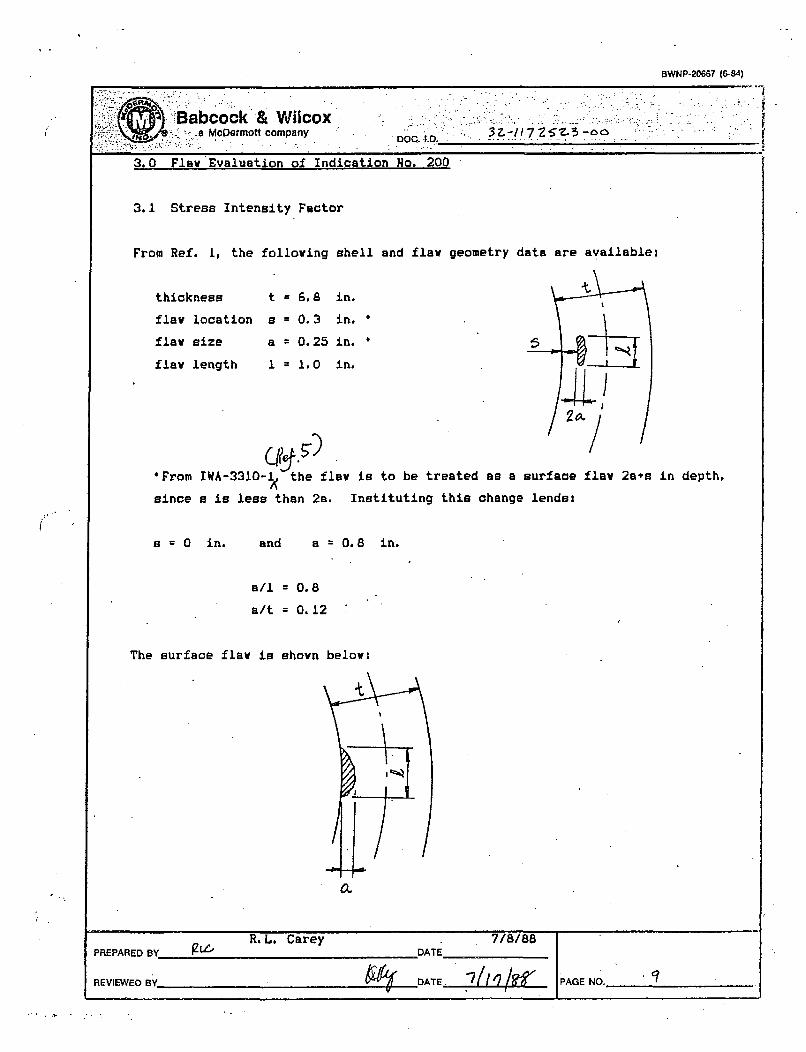
BWNP-20667 (6-84)
Babcock & Wilcox8McDermott company DOQ. I.O. 3-T ~ ~
A
3.0 Flaw Evaluation of Indication No. 200
3.1 Stress Intensity Factor
From Ref. I, the following shell and flaw geometry data are available:
thickness
flaw location
flaw size
flaw length
t=6.8
S=0.3
a 0.25
1 1.0
in.
in.
in.
in.
*From IWA-3310-1 the flaw is to be treated as a surface flaw 2ass in depth,
since s is less than 2a. Instituting this change lends:
fB = 0 in. and a = 0.8 in.
a/l f 0.8
a/t 0.12
The surface flaw is shown below:
0.
R. L. CareyPREPARED RY g L'( DATE
f1&•:-• PAGE NO.__ _ _REVIEWED BY -DATE..LV

BWNP-206M1 (6-84) .
Ba.bcock A Wilcox.-aMcDermott company ZCC -.0.17 Z-' -0
From Section 2.0 of this report, the highest longitudinal stress is that of the
Decay Heat transient, and the lowest longitudinal stress is g$5ok•ed +0
6e- ;&o- The stress distribution for the Oere--. '4-q j5d .-e4& is &s 411
S. ý -'7 jl
-M5 PEoI* I D
For the calculation of Ki.,. these stress distributions indicate a membrane
stress, a., of 7 ksl and bending stress, ab of 9 ksi. For K.,1 . the membrane
stress is C ksi and the bending stress is 0 ksi.
From Figs. A-3300-1, A-3300-3,
ratio of flaw depth to thickness
range of the figures, therefore,
and Hb=0.85 were selected.
and A-3300-5 of Ref. 5, the aspect ratio and
for this flaw were found to be outside of the
the conservative values of Q = 2.2 , H. = 1.1,
Since
and
K3
K3 S
6 61 H, (na/0)0'' + O Jib (no/Q)O'o
= 7 (1.1) In (0.8)/2.21'- + 9 (0.85) [n (0.8)/2.2J105
= 16.4 kseiin.
= 0 I½L47~'
K,= 16.4 -. 0 IG~.j ksi jin.
The stresses are for HUs and CDs.
3.2 Fatigue Crack Growth Analysis
PREPARED BY R. L. Carey DATE 7/8/88
REVIEWED BY DATE PAGE NO._ _ _
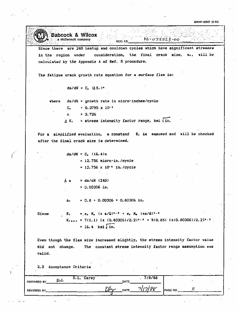
BWNP-20667 (6-84)
Babcock & Wilcox - -'a McDermott company .. "" -" , - -
Since there are 240 heatup and cooldown cycles which have significant stresses
in the region under consideration, the final crack size, a,, will be
calculated by tfie Appendix A of Ref. 5 procedure.
The fatigue crack growth rate equation for a surface flaw is:
da/dN = C. (AK),
where da/dN = growth rate in micro-inches/cycle
C, = 0.3795 x l0-3
n = 3.726
K, = stress intensity factor range, ksifn.
For a simplified evaluation, a constand K, is assumed and will be checked
after the final crack size is determined.
da/dH = C. (16.4)n
= 12.756 micro-in./cycle
= 12.756 x 10⁻⁶ in./cycle
a a da/dN (240)
= 0.00306 in.
a, = 0.8 + 0.00306 0.80306 in.
Since K, =.q, M. (H a/9)0'0 + ab Kl (na/Q)0'=
K. 8., = 7(1.1) In (0.80306)/2.2)0-3 + 9(0.85) (n(0.80306)/2.2]0.a
= 16.4 ksi in.
Even though the flaw size increased slightly, the stress intensity factor value
did not change. The constant stress intensity factor range assumption was
valid.
3.3 Acceptance Criteria
PREPARED BY R.L. CareyDATE 7/8/88
REVIEWED BY DATE `2 ! ~" PAGE NO. '

BWNP-20667 (6-84)
.-abcock & Wilcox.-:.a. McDermott company ~ 17Z 3 -6o~
Figure 1 shows that operating tempprature never comes down below 280°F unless
the pressure drops below the 100 psi level from 900 psi. Therefore, the
minimum operating temperature can be set at 280*F.
For the SG shell there is no appreciable fluence cummulation, hence,
RTDy = initial RTT
= 606F (Ref. 4)
T - RTNDT = 280-60 = 2206F
From Fig. A-4200-1 of Ref. 5, KX1 200 ksi4 in.
K:./K,..= 200/16.4 = 12.2 > 3.16 =f-
Therefore, this flay is acceptable by IWB-3612 standards.
4.0 Flay Evaluation of Indication No. 206
4.1 Stress Intensity Factor
From Ref. 2, the following sh
thickness t = 6.5 in
flaw location s = 0.0 in
flaw size a = 0.4 in
flaw length 1 = 0.9 in
a/l = 0.44
a/t = 0.06
From Fig. A-3300-1 of Ref. 5,0 = 24!
Lell and flaw geometry data-are available:
PREPARED BY
REViEWED AY
R.L. Carey 7/8/88DATE
DATE PAGE NO. IIJ

BWNP-20667 (6-84)
-;Babc'ock & Wilcox.a McDermott company OC .. -
Figs. A-3300-3 and A-3300-5 of Ref. 5 yield
H. : 1.1
M,= 0.95
Using the same stresses as those used in Section 3.0 of this report:
Since K, = a. K. (na/Q)O'o + a, Mi (na/9)6'=K,.,. = 7(1.1)[ (0.4)/2.1111-5 +' 9(0.,9)i[n (0.4)/1.110-'1
X 12.6 ksii.
and Kiag,.i = Y- 1L Ti-N.
Ks 12.6 0 2-12.10 ksi4ii
The stresses are for HUe and CDs.
4.2 Fatigue Crack Growth Analysis
Following the same equation given in Section 3.2,
da/dH C. (AK,)
where da/dN = growth rate in micro-inches/cycle
C, = 0.3795 x 10-
n = 3.726
K, = stress intensity factor range, ksi rin.
For a simplified evaluation, a constand K, is assumed and will be checked
after the final crack size is determined.
Ada/dH C, (i2,.L)a
= 4.*~ 7 ;micro-in. /cycle
=.777 x 10o- in./cycie
PREPARED BY • R.L. Carey 7/8/88
REVIEWED BY ATE'• /-1 PAGE NO._ _ _
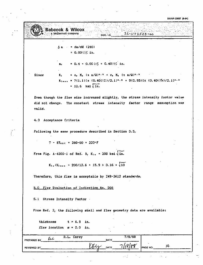
BWNP-20667 (6-84)
. :Babcock & Wilcox...-..ýa.McDermott -company D OC._________________________
5'si
= da/dH (240)
= 0.o00,111- in.
= 0.4 *0.001(5 0.40316, in.
=, r. (H a/Q)0 * 5 + Ob Mlb (ni a/g)*'5
=7(i1l)[n (0.40M:,.)/2.1)0- + 9(0.95)ln (0.40,11-55)/2.130-
= 12.6 ksifin
Since
Even though the flaw size increased slightly, the stress
did not change. The constant stress intensity factor
valid.
4.3 Acceptance Criteria
Following the same procedure described in Section 3.3,
T - RTmIT = 280-60 220oF
From Fig. A-4200-1 of Ref. 5, K,, = 200 ksi ýin.
K,,/K=.,. = 200/12.6 m 15.9 > 3.16 =
Therefore, this flaw is acceptable by IWB-3612 standards.
5.0 Flaw Evaluation of Indication No. 208
intensity factor value
range assumption was
5.1 Stress Intensity Factor
From Ref. 2, the following shell and flaw geometry data are available:
thickness t = 6.5 in.
flaw location s = 0.0 in.
PREPARED BY R. L. CareyDATE 7/8/88
REVIEWED BY -DATE '7/ glef PAGE .NO._____________

BWNP-20667 (6-84)
Babcock & Wlicoxa8 McDermott company.DC .. 3
flaw size a a 0.4 in.
flaw length I 1 1.0 in.
a/l = 0.4
a/t = 0.06
From Fig. A-3300-1 of Ref. 5,
0 = 1.9
Figs. A-3300-3 and A-3300-5 of Ref. 5 yield
M. 1.1
Mb 0.95
Using the same stresses as those used in Section 3.0 of this report:
Since Ki = a. H, (na/Q)6's * 06 fib (na/Q)"'
K,.,. 7(1.1)[n (0.4)/1.910-3 + 9(0.95)[E (0.4)/1.910-3
13.2 ksnii-
and K,.,. r 0
K, - 13.2- 2 ISfA ksei$j
The stresses are for HUs and CDs.
5.2 Fatigue Crack Growth Analysis.
Following the same equation given in Section 3.2,
da/dN = C. (AK,)=
where da/dN = growth rate in micro-inches/cycle.
C. = 0.3795 x 10⁻³
n 3. 726
....... R.L. Carey 7/8/88PREPARED BY 0 PAGDATE__

BWNP-20667 (6-84)
* Babcock&'Wilcox _____
a McDermott company.; - oszcu..`a o
K, - stress intensity factor range, ksi .ýJn.
For a simplified evaluation, a constand K, is assumed and
after the final crack size is determined.
will be checked
da/dNC. (,Z No,
5.§ micro-in. /cycle
5.61;'&x 10-' in./cycle
a = da/dN (240)
= 0.0031(p in.
a, = 0.4 * 0.00 .1ý = 0.401iA in.
Since K,
KI a a
a. M. (n a/0)05 + a, Mi. (n a/0)0.3
7(1.1)(n (0.40453)/1.9)0'' * 9(0.95)En (0.4013(0)/1.930-5
13.2 ksi sfii
size increased slightly, the stress intensity factor value
The constant stress intensity factor range assumption was
Even though the flaw
did not change.
valid.
5.3 Acceptance Criteria
Following the same procedure described in Section 3.3,
T - RTwr = 280-60 = 220*F
From Fig. A-4200-i of Ref. 5, KI= 200 ks n
Kj,/Kj,,, 200/13.2 15.2 > 3.16 =4Ti
Therefore, this flaw is acceptable by IWB-3612 standards.
R. L. Carey 7/8/88PREPARED BY )C., DATE
REVIEWED BY DATE .. PAGE NO._ _ _

BWNP-20667 (6-84)
'B~abcock & Wilcox.-a McDermott company . 7-. Z 3 --C'O;;fi•'j• • ::•::.•..:",...: . .. ~ ~ DOC " o .D.. ;:.. ..... ...... - -'
6.0 Flaw Evaluation of Indication Ho. 210
6. 1 Stress Intensity Factor
From Ref. 2, the following shell and flaw geometry data are available:
thickness t = 6.5 in.
flaw location B = 0.0 in.
flaw size a = 0.6 in.
flaw length 1 = 0.9 in.
a/I = 0.67
a/t = 0.09
From Fig. A-3300-1 of Ref. 5,
Q c-2.2
Figs. A-3300-3 and A-3300-5 of Ref. 5 yield
H. 1.1
hb 0.88
Using the same stresses as those used in Section 3.0 of this report:
Since Kt t 0. H, (Ka/Q.' + a, H, (na/Q)0
K=,, 7(l.1)[nt (0.6)/2.220--l + 9(0.88)(n (0.6)/2.210-5
= 14.5 ksi
and K1 ,.
K, = 14.5 - 0 = -.S ksili
The stresses are for HUe and CDs.
6.2 Fatigue Crack Growth Analysis
PPD [L R.L. Carey 7/8/88PREPARED BYDAE________
REVIEWED BY DATE PAGE NO.

BWNP-20667 (684)I
!•!ii~z•); Babcock & Wilcox_:___________;_______,__a;: McDermott company Doc D. 3 Z- ,
Following the same equation given in Section 3.2,
da/dH = C. (A)X:)
where da/dH
C,
n
6 K,
= growth rate in micro-inches/cycle
= 0.3795 x 10-3
= 3.726
= stress intensity factor range, ksi in.
For a simplified evaluation, a constand K, is assumed and will be checked
after the final crack size is determined.
\da/dN C. (14. 5).
= S.• micro-in. /oycle
=z. x 10-t in./cyole
a da/dK (240)
=0.0011'. in.
a, = 0.6 + 0.00101p 0.60193 in.
Since K,
Ki a
(I. M. (n a/Q)0'3 + o, No (i a/Q)0'3
7 7(1.,1)[n (0. 60H10/2. 2)*.- + 9(0. 88)[n (0. 601ý1 )/ 2. 2]0-5
14.5 ksi
w size increased slightly, the stress intensity factor value
The constant stress intensity factor range assumption was
Even though the f a
did not change.
valid.
6.3 Acceptance Criteria
Following the same procedure described in Section 3.3,
PREPARED BY R.L. CareyDAT 7/8/88
REVIEWED BY,' DATE 7 ' ?'PAGE NO._________

I
BWNP-20667 (6-84)
".. -McDermott company . 0.D . ".0. -2- ... ?3
T - RTm, 7 280-60 = 220"F
From Fig. A-4200-1 of Ref. 5, K1. 200 ksefi~
200/14.5 = 13.9 > 3.16 , F1
Therefore, this flaw is acceptable by IWB-3612 standards.
.kO Flaw Evaluation .of Indication No. 212
7. 1 Stress Intensity Factor
P•2 om Ref. 2, the following shell and flaw geometry data are availablei
thickness t = 6.5 in.
flaw location s r 0.0 in.
flaw size a = 0.5 in.
flaw length I = 1.4 in.
a/1 = 0.36
a/t = 0.08
Prom Fig. A-3300-1 of Ref. 5,
1.8
pigs. A-3300-3 and A-3300-5 of Ref. 5 yieldt(. = 1.1L
- Il 0. 95
Using the same stresses as those used in Section 3.0 of. this report:
Since K, = M. (na/Q)- + a, Mt (na/T)W
S 1.2 . . + (.95)n (0.5)/1.83=15. 2 ksiin
1ý'R"ýPAR:ED BY SR.L. Carey_DATE
K!•3 DATE*
7/8/88
-.____ AE O_____

OWNP-20687 (864)
/0 a cem omPaY. -OOID
and K 3,. 0
A X, 15.2 - = (1 .r ksi Win.
The stregoeas are for HUa and CJs,
7.2 Fatigue Crack Growth Analysis'
Following the same equation given in Section 3.2,
da/dN n C, (,&X )1
where da/dH
C,
Y1'f
* growth rate in micro-inohes/oyole
* 0.3795 x 10"3
= 3.726
* stress intensity factor range, knl in,
For a simplified evaluation, a conatand K, is assumed and- will be checked
after the final crack size is determined,
da/dH C. (1i4,011-
'.(lI rmicro-in./oyale
x 1O"6 in. /cyole
6 a da/dN (240)
O.O001 in.
a1 0.5 + 0.O0,2ýl = 0.50N1 in.
Since xl
K,
g8 H.~ ( n a/a1) 6- + (yb 14h 01aQO
r15. 2 k aI in.
PREPARED B RL, Carey DATE 7/8/BB
REVIEWED BY, 0't DATE PAGE NO. .... _ __

BWNP-M0687 (844)
2 i~Y7) bacock& Wilcox-'~"-a -vomiah
Even though the flaw size increased slightly, the stress intensity factor value.
did not change. The constant stress intensity factor range. assumption, was
valid.
7.3 Acceptance Criteria
Following the same procedure described in Section 3.3,
T - RTNoT = 280-60 r 2206F
From Fig. A-4200-1 of Ref. 5, K,, r 200 ksi n,
Kj, /Kt... = 200/15.2 s 13.2 > 3,16 -1
Therefore, this flaw is acceptable by IWB-3612 standards..
8.0 Conolusion
The five selected indications are found to be anceptable by IWB-3612 criteria.
PREPARED BY. £ce R . ,, Carey _ DATE_
REVIE IED BY .DATE PAGE NO. a

OWNP-2o0e? (644)
ý,SbOock A& Wilcox.i. M900rMolt bompany.
. . IJ~~OCIAD 3 1 .3b
/.-
9.0 References
I. O&W Volumetrio Examination Evaluation Report, TED 88-045, June.16, 1988.
2. O&W Volumetrio Examination Evaluation Report, TED 88-044, June 15, 1988,;
3. B&W Document, "Design Report,' Toledo Edison Company & C.E.I., B&W Contract
No. 620-0014-55, NPGD Hicrofilm Roll Ho. 80-15 and 80-16,
4. O&W Document No. 18-1149327-00, "Functional Specification for Reactor
Coolant System," Contract No. 582-7151, Toledo Edison Co., NSSE4.
5. ASME Boiler and Pressure Vessel Cdde, Section XI, 1977 Edition,
_m ~1
PREPAtIM13Y ej R. L,# Cnrey DATE 7/8/88
REVIEWED BY_.-. DATE WO If PAGE NO. ________
_._j