attention: mr g. nel project 165-18 – durbanville, … · compressible (in-situ cbr values of...
TRANSCRIPT
Tel: +27 21 671 4274/80 Fax: +27 21 671 4277 email: [email protected] address: Postnet Suite 177, Private Bag X3, Plumstead, 7801, Cape Town
Physical address: Unit b02, Clareview Business Park, 236 Imam Haron Road, Claremont, 7708, Cape Town, South Africa
CC no. CK96/62430/23 VAT no: 4180186159 Core Geotechnical Consultants CC Members: JRC Yates – MSc.(Eng.Geol.),DIC,BSc(Geol.),MSAIEG,Pr.Sci.Nat., RL Yates – Dip. Coaching & Communication (SACAP), CEA
16 October 2018
Rupipi (Pty) Ltd25 Bonair RoadRondebosch7700
ATTENTION: Mr G. Nel
Dear Gerhard
PROJECT 165-18 – DURBANVILLE, COUNTRY WAY, ERVEN 40 & 72, - GEOTECHNICAL INVESTIGATION FOR STORMWATER MANAGEMENT PLAN
As requested, we have carried out a geotechnical investigation, as part of the stormwater management plan, for the new proposed development on erven 40 & 72, located in Country Way in Durbanville.
The site is an approximately 2.73 ha, rectangular piece of land. The site is currently occupied by a residential structure, as well as stables and horse paddocks.
A residential area bounds the site to the, south, east and north, while a natural lower lying wetland/marshy area is located close to the western site boundary. The regional and site topography slopes down from the south-east and east, towards the lower lying, wet areas located north-west and west of the site (approx 1(v):15(h) to 1(v):35(h)).
The proposed development will also consist of multiple small cul-de-sacs providing access to the new residential development, with a new access road along the western boundary, providing the main accessto the estate.
The main aims of the investigation were as follows:-
a) Determine site geotechnical conditions and provide classifications including detailed soil profile and groundwater occurrences within the zone of influence of the proposed structures and services associated with the development.
b) Assess both the geotechnical and the permeability properties of the soils as part of the stormwater management plan and to assess the potential for the use of permeable paving for the new access roads.
c) Comment on related geotechnical aspects, including earthworks, excavation conditions, lateral support, foundation design, materials usage and drainage design, where applicable.
1. Nature of the investigation
The investigation comprised the following:-
• A desk study, to assess regional site geology and subsurface geohydrological conditions.• Excavation of four test pits, excavated using a digger-loader, along the proposed main access
road, in order to visually inspect soils underlying the site, take representative samples and observe groundwater conditions.
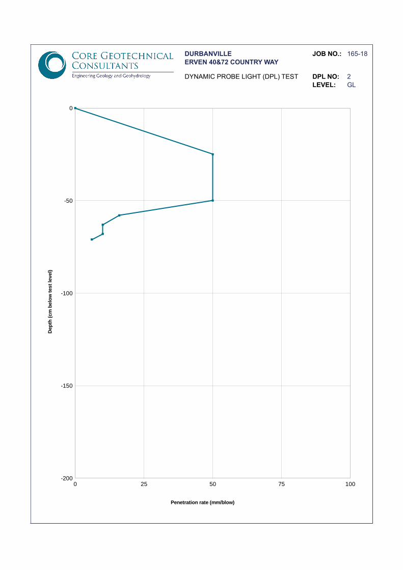
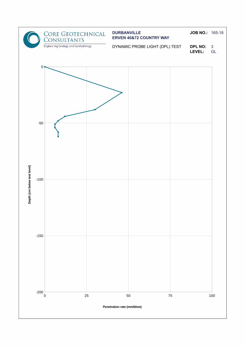
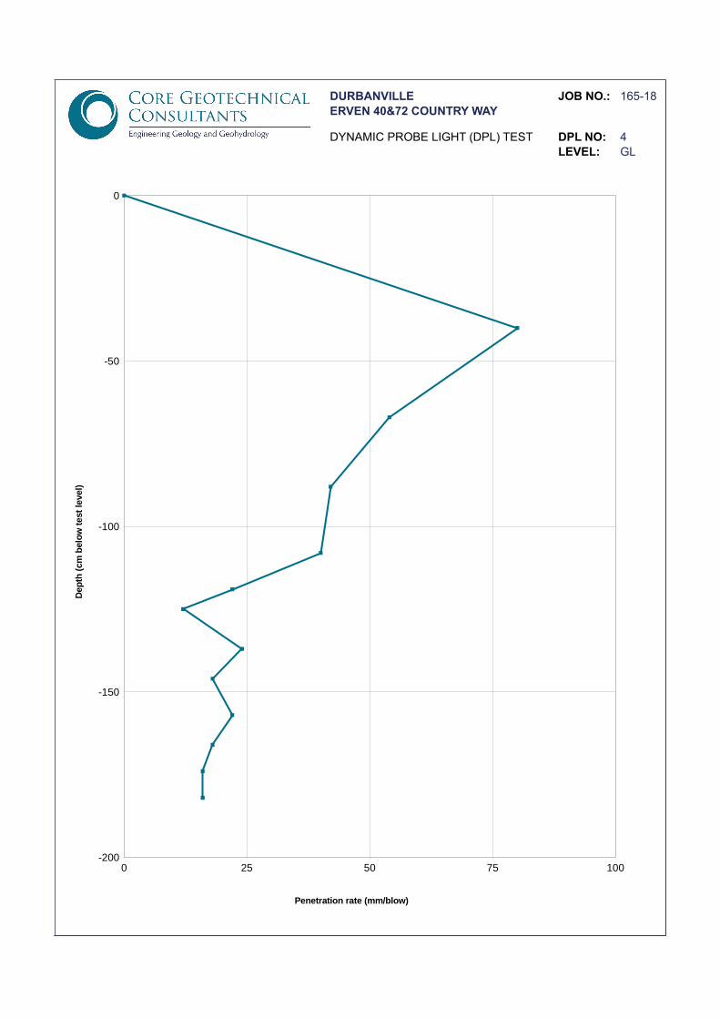
• DPL (dynamic probe light) testing was conducted at each test pit location to determine a measure of in-situ soil density and determining soil strength and compressibility with depth.
• Double Ring Infiltrometer Tests were conducted from surface at three locations, in order to determine in-situ permeability and infiltration rates.
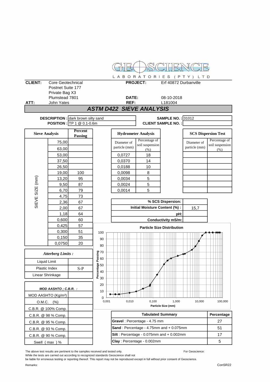
• Laboratory testing, namely indicator testing (grading analysis and Atterberg Limits), was conducted on selected samples in order to determine soil engineering properties.
• A falling head permeability test was also conducted on a remoulded sample (remoulded to the same bulk density as that of the in-situ soil) in order to determine an indication as to the permeability properties of the deeper soil profile.
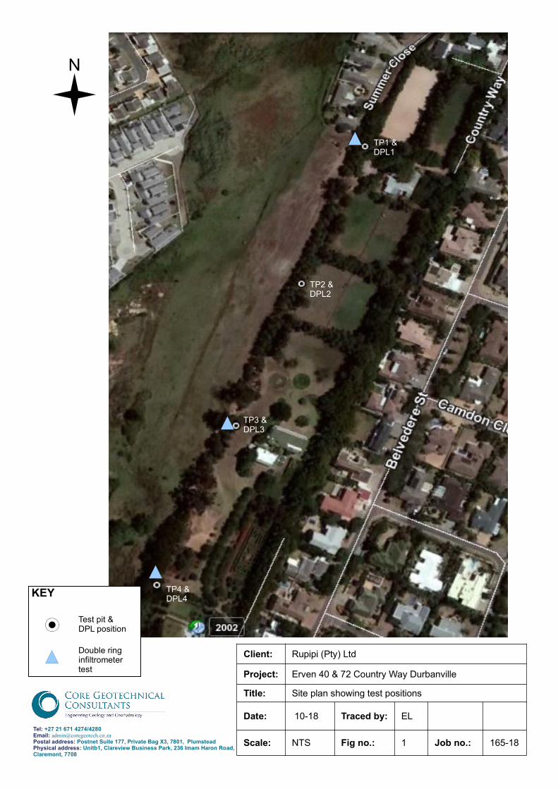
Test pit, DPL and double ring infiltrometer test positions are shown on the enclosed site plan. Copies of the recorded test pit soil profiles, DPL profiles and soils laboratory test results also attached.
2. Site geology and geohydrology
2.1 Site geology
Regionally, the entire area is underlain by unconsolidated clayey, silty and sandy deposits of Quaternary to Recent age and of transported origin. The unconsolidated transported soils are underlain by residual and weathered shale of the Malmesbury Group.
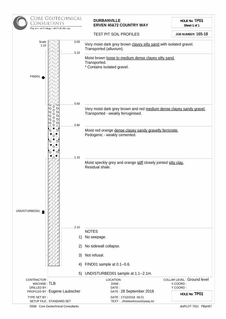
The general soil profile on site (test pits TP1-TP3) consists of transported (alluvially), clayey silty sands at surface that extend to a depth of between 0.3m and 0.6m. These silty sandy soils overly anoriginally transported, gravelly clayey sand and clayey sandy gravel horizon that has undergone various degrees of ferruginization, but is generally weakly cemented. In test pits (TP2 & TP3), a thinly developed (0.2m to 0.3m thick) transported gravelly silty clay horizon underlies the upper transported sandy and gravelly soils.
Residual shale of the Malmesbury Group, consisting of silty clay, underlies the transported and pedogenic soils (where encountered). The residual shale generally occurs at a depth of between 0.8m and 1.1m below surface.
In the south-western part of the site (test pit TP4), an uncontrolled fill material, of variable thickness(1.5m thick in TP4), overlies the natural soils in the area. This fill material consists of sandy silty clay(most likely taken from cut elsewhere nearby) with variable amounts of rubble and other waste material. This fill material has been used to create an elevated garden terrace platform, that is raised relative to the lower lying adjacent wetland/drainage line area.
2.2 Site geohydrology
A perched groundwater table was only encountered in test pit (TP4) at a depth of 1.7m (close to the original natural ground level of the nearby drainage/wetland area). A perched water table may however develop at, or close to the upper contact of the very low-permeability residual and clayey soils and thus develop within 1.0m of surface.
Due to the regional sloping topography and shallow depth of the residual soils, stormwater will likely preferentially drain downslope as “runoff” towards the drainage line/wetland area located west of the site, rather that infiltrate the surface soils. It is also expected that ponding and muddy conditions will develop in flatter, lower lying areas.
3. Geotechnical evaluation
Laboratory test results are summarized in Table 3.1, while permeability test results are summarized in Table 3.2 Based on the field investigation and laboratory testing, the following points relating to the geotechnical conditions of the site may be made:-a) The uncontrolled fill, encountered in test pit (TP4), and also expected in other raised platform
areas on site, is highly variable in composition and is highly compressible. These soils are unsuitable for founding purposes or for use in construction. They would need to be removed and replaced with a suitable quality granular material, or alternatively foundation in these areas would need to extend through this material to found on deeper, more competent soils.

b) The DPL testing conducted from surface indicates the transported silty sandy soils to be highly compressible (in-situ CBR values of approximately 3-5) to a depth of approximately 0.5m belowsurface. These soils are unsuitable for founding purposes or for use as a subgrade without some form of recompaction. Below this depth, soils are generally low to moderately compressible andshould thus form a competent founding horizon, provided bearing pressures are limited.
c) In terms of material properties the transported silty sands are slightly plastic. They are expected to have a low post-compaction strength and should thus only be be suitable for use as a general fill material.
d) The transported and residual clay has a moderate plasticity and a very low post compaction strength is expected. Poor workability will make these soils unsuitable for use in construction.
e) Permeability testing was conducted both in-situ (using a double ring infiltrometer test at surface) and in the laboratory (using a falling head permeability test conducted on a remoulded sample that was remoulded to the same bulk density as was determined from an undisturbed sample). This undisturbed sample was taken within the transported clay from within test pit (TP3). The permeability test results are summarized in Table 3.2. The results indicate the transported silty sands located at surface across most of the site have poor infiltration capacity properties. The deeper transported clay classifies as “practically impervious”. Similar “practically impervious” permeability properties are also expected in the underlying residual clay soils. Although infiltration capacity within the uncontrolled clayey fill material classifies as moderate to poor, this material is both highly variable and highly compressible in its current state. It is also not suitable for use as a subgrade material below the pavements.
f) No difficulty in excavation, to a depth of at least 2.5m, is expected within the fill, transported or residual soils.
g) Sidewall collapse only occurred within the uncontrolled fill. Excavations deeper than 1.5m will however still require shoring or battered sidewalls for safety purposes.
h) The perched groundwater was only encountered in Test pit (TP4) at a depth of 1.7m. A perchedgroundwater table may however develop at, or close to the upper contact of the transported and residual clay during wet winter periods, especially along the western property boundary. Due to the sloping nature of the regional topography, there is also an associated risk of stormwater runoff downslope towards the west during periods of heavy rains. Excavations close to the western property boundary (near the adjacent wetland/marshy area) will likely require dewatering. During wet winter periods dewatering of excavations may also be required in other areas.
Table 3.1 Summary of soils engineering properties
Testpit Depth (m) Soil/test description LL PI LS MC GM USCS Soil Class
TP1 0.1-0.6 Transported silty sand - SP - 15.7 1.56 SM
TP3 0.6-0.9Transported gravelly
sandy silty clay 30 14 7 21.1 0.65 CL
TP4 1.5-2.3 Transported silty sand - - - 23.4 0.81 SM
Key: LL – liquid limit. PI – plasticity index. MC – in-situ moisture content. GM – grading modulus. SP – slightly plastic
Table 3.2 Summary of soil permeability properties
Testposition
Testdepth Soil description Test type
USCS SoilClass
Infiltration capacity/Coefficient of permeability(k)
m/s cm/s classification
TP1 surface Transported silty sand Double ringinfiltrometer SM 7.1E-0.6 7.1E-0.4 Poor
TP3 surface Transported silty sand Double ringinfiltrometer SM 1.8E-06 1.8E-04 Poor
TP3 0.6-0.9Transported gravelly
sandy silty clayFalling headpermeability CL 2.27E-10 2.27E-08
Practicallyimpervious
TP4 surfaceUncontrolled sandy silty
clay FillDouble ringinfiltrometer variable 7.5E-05 7.5E-03
Moderate topoor
4. Recommendations for design and construction
4.1 Excavation conditions and lateral support
Excavations within the uncontrolled fill, transported soils, weakly ferruginized soils and residual soils, classifies as “soft excavation” in terms of the SANS 1200 D Earthworks Specification.
Conventional earthmoving equipment such as digger-loaders and tracked excavators should provide the most economic method of excavation.
Although sidewall collapse was only observed within the uncontrolled fill, excavation deeper than 1.5m will require shoring or battered sidewalls for safety purposes. Sidewalls within the transported sandy soils and uncontrolled fill would need to be battered to an angle of not more than 45o to the horizontal, while sidewalls within the transported and residual clays should be battered to an angle of not more than 65o to the horizontal.
During wet winter periods, excavations may require dewatering, especially in lower lying areas adjacent to the wetland/marshy areas located just west of the site. It should be possible to control seepage using conventional dewatering methods such as bailing or pumping from sumps.
The site is located on ground sloping down from the south-east and east, towards the north-west and west. It is thus likely that as part of the proposed development, terracing will be required for the new structures. Careful consideration to earthworks, temporary lateral support during construction, as well as the design of permanent lateral support will required. The following would need to be noted in this regard:-
• Cuts deeper than 1.5m will require battering of sidewalls to a safe angle of not more than 65 degrees to the horizontal (within the clayey soils). Due to the cohesionless nature of the transported soil at surface, trimming back of this upper horizon to not more than 45o to the horizontal, may be required to prevent ravelling. Excavations deeper than 3.0m will require more consideration with regards to formal lateral support measures.
• For areas where sufficient space is available to allow the required battering of cut sidewalls and for the full cut sections of the terrace to be conducted simultaneously, the full retaining walls can be constructed in one operation.
• In areas where there may be insufficient space available in this regard (possibly along eastern site boundary), a temporary support berm could be left in place within the final cut linesin order to minimize the area of loss of support during earthworks. Allowance should be made in the lateral support design for the permanent retaining wall in this area to be constructed in 3.0 m wide slots cut alternately into the temporary berm in order to minimize areas of loss of support.
• The new retaining walls should be founded within the stiff transported or residual shale. These soils are expected at or close to final cut level. Allowable bearing pressures of the soils on site are discussed in more detail in Section 4.2.
• The retaining walls would all need to be designed for active earth pressures, pore water pressures as well as any surcharge imposed from structures located further upslope on higher lying terraces. Both the internal wall stability and the overall global stability criteria should be assessed.
• Earthworks are expected to encounter seepage during winter periods. It should be possible to control any seepage into open excavations through conventional pumping from sumps.
• Full drainage should be provided behind all retaining walls.• Further investigation may be required with regard to the suitability of the lateral support
design, once earthworks are finalized.
4.2 Foundations
On the basis of the existing geotechnical information, the following regarding foundation design, should be noted:-
• The uncontrolled fill is unsuitable for founding purposes. These soils would need to be removed to spoil and where necessary replaced with a suitable quality and suitably compacted granular material. Alternatively any foundations inthese areas would need to extend through thismaterial in order to found on the deeper, more competent soils.
• Transported silty sandy soils are highly compressible to a depth of 0.5m below surface. These soils are also unsuitable for founding in their current state without recompaction.
• Below this depth, the transported and residual clays are moderately compressible and thus suitable for founding, provided that bearing pressures are limited.
• The residual shale soils have the potential for low potential for heave movement (5-10mm). This would need to be factored into the design of the structure.
• Due to the likelihood of structure being founded on cut terraces, depending on the final cutdepths, there will be variability in the soils encountered at final cut levels. Founding on different soil types (combination of compressible transported silty sands, and moderately compressible transported and residual clays) carries a greater risk of differential movement. To limit this risk it is recommended to found the entire structure on similar soils.
• The maximum allowable bearing pressures of the soils on site are summarized in Table 4.1.Table 4.1. Maximum allowable bearing pressures of soils on site.
Soil description Depth (mbgl) Maximum allowable bearing pressure (kPa)
Uncontrolled fill Up to 1.5m (depending on area)
Not suitable for founding purposes
Loose transported silty sands 0.5m 50 (without recompaction)75 (after nominal compaction from surface)
Stiff transported clay/ gravellyclayey soils/residual shale
0.5-1.1m 150
The following founding options are thus recommended:
1) In order to limit the risk of differential settlement, it is recommended to found structures on similar soils. Found structures through any uncontrolled fill or compressible transported soils andonto the stiff transported or residual clays, expected at or close to final cut levels. Bearing pressures would need to be limited to not more than 150kPa. Units can be found using either strip footings or alternatively using a system of piers and groundbeams (if deeper founding is required to reach suitable founding soils). Piers can be constructed using bases and columns or
through the use of cement stabilized backfill. Pier excavations may require dewatering during wet winter periods. Maximum allowable bearing pressures are summarized in Table 4.1. Final founding depth would thus depend on final cut levels
2) Found the structures at final cut level using stiffened concrete raft foundations. Bearing pressures would however need to be limited to to 50kPa. Differential settlement could be expected. This would however depend on final loading conditions, dimensions of the raft foundation and the design of the underlying terrace platform.
Any fill terraces would need to be constructed using a suitable quality granular material compacted to at least 95% Mod AASHTO maximum dry density, over its full depth.
Surface beds can be founded conventionally on terrace soils once this material has been compactedto at least 93% Mod. AASHTO maximum dry density. Reinforcement of the surface beds and isolating them from walls to accommodate expected heave, will minimize the risk of cracking. Alternatively surface beds may be designed as suspended slabs, in which case in-situ soils can be leftin place (as is) and used only as a back-shutter.
It is recommended that modified normal construction techniques be applied to cater for potential heave movement (5-10mm). Suitable measures would include additional reinforcement in strip footings (if applicable), in brickwork in plinth walls and in brickwork above doors and windows, reinforcement of surface beds, articulation of brick panels using construction joints, as outlined in Section 9 (refer also to NHBRC Home Building Manual).
The main aim of this investigation was to assist in the stormwater design of the proposed development. Test pits were thus limited to the western boundary of the site. It is thus recommended that a geotechnical specialist is consulted once the earthworks designs are complete.An additional geotechnical investigation may be required. At the very least it is recommended that ageotechnical specialist inspect earthworks during the construction phase as well as inspect foundation excavations before casting concrete to ensure suitable founding soils compatible with the foundation design.
4.3 Drainage design
Following the geotechnical investigation, the following should be noted pertaining to site drainage design and stormwater management:-
• The transported silty sands have a poor infiltration capacity, while the stiff transported clays and residual clays will be practically impervious with regards to stormwater infiltration (referto Section 3). There is thus a risk of ponding and muddy conditions developing at surface, especially in flatter lying areas and in areas close to the adjacent natural drainage line.
• As a result of the highly compressible nature of the transported silty sands (within the upper 0.5m from surface), recompaction will be required before these soils are suitable for use as a subgrade. Even if recompaction was limited from surface to at least 93% Mod AASTHO maximum dry density (minimum compaction that would be required), this would further lower infiltration rates and permeability properties of these already low-permeability soils.
• As a result of the sloping site topography, groundwater and stormwater will tend to follow the natural contours, running from upslope (east and south-east) down towards the west and north-west, towards the natural drainage line and wetland area located west of the site.As a result of the poor infiltration rates stormwater will tend to drain downslope as “runoff” during periods of heavy rains. There is is thus also an associated risk of erosion occurring in unvegetated sloped areas.
• A shallow perched groundwater table is expected to develop within 0.5m to 1.0m of surface, in lower lying areas close to western site boundary.
• Given these geotechnical considerations and the properties of the underlying soils, the use of permeable paving would only be recommended if suitable site drainage and design precautions are considered (refer mainly to (i) below).
With regards to site drainage and stormwater management, the following options could however beconsidered:-
i. Depending on final required elevation levels, if the use of permeable paving is to be considered,it will likely be necessary to either first:
a) Undercut the low-permeable transported silty sands, clay and residual shale by 0.60-0.8 m and then import a free draining, granular subgrade material compacted to at least 93% Mod AASHTO maximum dry density, to directly underlie the permeable paving.
b) Alternatively raise the existing elevation levels by at least 0.50-0.8m using a similarly compacted granular material. The main aim would be to provide a suitably compacted subgrade with sufficient drainage properties to directly underlie the paving and to sufficientlyraise the existing elevation levels above that of the expected perched water table, which may rise by approximately 0.5m from current levels during wet winter periods.
c) In addition to this and depending on the design requirements with regards to allowable permeability below the permeable paving, the imported subgrade may require a composite subsurface drainage system with sufficient collector drains installed beneath the paved area. A suitable geotextile material can help improve permeability and prevent washing through offiner material into the drainage pipes and filter.
ii. The design of effective collection and disposal off site, of storm water from upslope areas, as well as water from down pipes of structures, and the regular checking of wet services for leaks, isrecommended.
iii. Consideration can be given to the installation of a cutoff drain along the upslope side of the site in order to intercept and channel away any runoff from areas further upslope.
iv. Full drainage should be installed behind all retaining walls.
v. In light of the potential for a perched water table occurring within 0.5m to 1.0m of surface in parts of the site, damproofing measures should be considered for future structures.
vi. There is a risk of ponding of water on surface in any flat lying areas, as well as the potential for marshy conditions along the western site boundary. For such areas, the grading of slopes to promote runoff towards stormwater catchment services, would need to be considered.
vii.The implementation of sound water management measures in accordance good engineering practice should prevent water ingress into any soils below foundations and therefore minimize risks of any associated differential movements, as well as minimize the risk of localized areas of flooding.
We trust that this report meets your present requirements and would be pleased to discuss any aspects with you.
Kind regards
JOHN YATES EUGENE LAUBSCHER
encl. Site planSoil profiles (4)DPL profiles (4)Laboratory test results (4)
Tel: +27 21 671 4274/4280Email: [email protected] Postal address: Postnet Suite 177, Private Bag X3, 7801, PlumsteadPhysical address: Unitb1, Clareview Business Park, 236 Imam Haron Road, Claremont, 7708
KEY
N
Client: Rupipi (Pty) Ltd
Project: Erven 40 & 72 Country Way Durbanville
Title: Site plan showing test positions
Date: 10-18 Traced by: EL
Scale: NTS Fig no.: 1 Job no.: 165-18
Test pit & DPL position
Double ring infiltrometer test
TP1 & DPL1
TP2 & DPL2
TP3 & DPL3
TP4 & DPL4
FIND01
UNDISTURBED01
DURBANVILLEERVEN 40&72 COUNTRY WAY
TEST PIT SOIL PROFILES
HOLE No: TP01Sheet 1 of 1
HOLE No: TP01Sheet 1 of 1
HOLE No: TP01Sheet 1 of 1
HOLE No: TP01Sheet 1 of 1
JOB NUMBER: 165-18JOB NUMBER: 165-18
0.10
0.00
0.60
0.80
1.10
2.10
Very moist dark grey brown clayey silty sand with isolated gravel.Transported (alluvium).
Moist brown loose to medium dense clayey silty sand.Transported.* Contains isolated gravel.
Very moist dark grey brown and red medium dense clayey sandy gravel.Transported - weakly ferruginised.
Moist red orange dense clayey sandy gravelly ferricrete.Pedogenic - weakly cemented.
Moist speckly grey and orange stiff closely jointed silty clay.Residual shale.
Scale1:10
NOTES1) No seepage.
2) No sidewall collapse.
3) Not refusal.
4) FIND01 sample at 0.1--0.6.
5) UNDISTURBED01 sample at 1.1--2.1m.
CONTRACTOR :MACHINE :
DRILLED BY :PROFILED BY :
TYPE SET BY :SETUP FILE :
TLB
Eugene Laubscher
STANDARD.SET
LOCATION:DIAM :DATE :DATE :
DATE :TEXT :
28 September 201817/10/2018 09:21..0\network\countryway.txt
COLLAR LEVEL :X COORD :Y COORD :
Ground level
dotPLOT 7021 PBpH67D068 Core Geotechnical Consultants
HOLE No: TP01HOLE No: TP01HOLE No: TP01HOLE No: TP01
DURBANVILLEERVEN 40&72 COUNTRY WAY
TEST PIT SOIL PROFILES
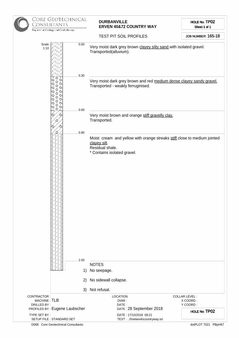
HOLE No: TP02Sheet 1 of 1
HOLE No: TP02Sheet 1 of 1
HOLE No: TP02Sheet 1 of 1
HOLE No: TP02Sheet 1 of 1
JOB NUMBER: 165-18JOB NUMBER: 165-18
0.30
0.00
0.60
0.80
2.00
Very moist dark grey brown clayey silty sand with isolated gravel.Transported(alluvium).
Very moist dark grey brown and red medium dense clayey sandy gravel.Transported - weakly ferruginised.
Very moist brown and orange stiff gravelly clay.Transported.
Moist cream and yellow with orange streaks stiff close to medium jointedclayey silt.Residual shale.* Contains isolated gravel.
Scale1:10
NOTES1) No seepage.
2) No sidewall collapse.
3) Not refusal.
CONTRACTOR :MACHINE :
DRILLED BY :PROFILED BY :
TYPE SET BY :SETUP FILE :
TLB
Eugene Laubscher
STANDARD.SET
LOCATION:DIAM :DATE :DATE :
DATE :TEXT :
28 September 201817/10/2018 09:21..0\network\countryway.txt
COLLAR LEVEL :X COORD :Y COORD :
dotPLOT 7021 PBpH67D068 Core Geotechnical Consultants
HOLE No: TP02HOLE No: TP02HOLE No: TP02HOLE No: TP02

UNDISTURBED03
DURBANVILLEERVEN 40&72 COUNTRY WAY
TEST PIT SOIL PROFILES
HOLE No: TP03Sheet 1 of 1
HOLE No: TP03Sheet 1 of 1
HOLE No: TP03Sheet 1 of 1
HOLE No: TP03Sheet 1 of 1
JOB NUMBER: 165-18JOB NUMBER: 165-18
0.30
0.00
0.60
0.90
1.60
Very moist dark grey brown clayey silty sand with isolated gravel.Transported(alluvium).
Very moist dark grey brown and red medium dense clayey sandy gravel.Transported - weakly ferruginised.
Very moist brown and orange stiff gravelly clay.Transported.
Very moist cream and orange stiff closely jointed silty clay.Residual shale.
Scale1:10
NOTES1) No seepage.
2) No sidewall collapse.
3) Not refusal.
4) UNDISTURBED03 sample at 0.6--0.9m.
CONTRACTOR :MACHINE :
DRILLED BY :PROFILED BY :
TYPE SET BY :SETUP FILE :
TLB
Eugene Laubscher
STANDARD.SET
LOCATION:DIAM :DATE :DATE :
DATE :TEXT :
28 September 201817/10/2018 09:21..0\network\countryway.txt
COLLAR LEVEL :X COORD :Y COORD :
dotPLOT 7021 PBpH67D068 Core Geotechnical Consultants
HOLE No: TP03HOLE No: TP03HOLE No: TP03HOLE No: TP03
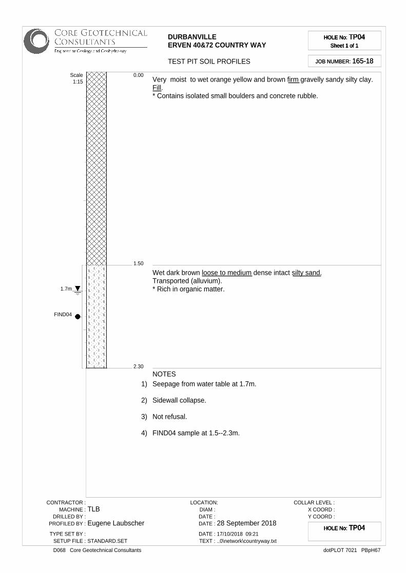
1.7m
FIND04
DURBANVILLEERVEN 40&72 COUNTRY WAY
TEST PIT SOIL PROFILES
HOLE No: TP04Sheet 1 of 1
HOLE No: TP04Sheet 1 of 1
HOLE No: TP04Sheet 1 of 1
HOLE No: TP04Sheet 1 of 1
JOB NUMBER: 165-18JOB NUMBER: 165-18
1.50
0.00
2.30
Very moist to wet orange yellow and brown firm gravelly sandy silty clay.Fill.* Contains isolated small boulders and concrete rubble.
Wet dark brown loose to medium dense intact silty sand.Transported (alluvium).* Rich in organic matter.
Scale1:15
NOTES1) Seepage from water table at 1.7m.
2) Sidewall collapse.
3) Not refusal.
4) FIND04 sample at 1.5--2.3m.
CONTRACTOR :MACHINE :
DRILLED BY :PROFILED BY :
TYPE SET BY :SETUP FILE :
TLB
Eugene Laubscher
STANDARD.SET
LOCATION:DIAM :DATE :DATE :
DATE :TEXT :
28 September 201817/10/2018 09:21..0\network\countryway.txt
COLLAR LEVEL :X COORD :Y COORD :
dotPLOT 7021 PBpH67D068 Core Geotechnical Consultants
HOLE No: TP04HOLE No: TP04HOLE No: TP04HOLE No: TP04
10.5
Name
Name
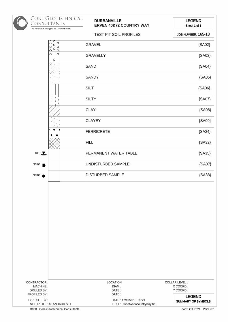
DURBANVILLEERVEN 40&72 COUNTRY WAY
TEST PIT SOIL PROFILES
LEGENDSheet 1 of 1
LEGENDSheet 1 of 1
LEGENDSheet 1 of 1
LEGENDSheet 1 of 1
JOB NUMBER: 165-18JOB NUMBER: 165-18
GRAVEL {SA02}
GRAVELLY {SA03}
SAND {SA04}
SANDY {SA05}
SILT {SA06}
SILTY {SA07}
CLAY {SA08}
CLAYEY {SA09}
FERRICRETE {SA24}
FILL {SA32}
PERMANENT WATER TABLE {SA35}
UNDISTURBED SAMPLE {SA37}
DISTURBED SAMPLE {SA38}
CONTRACTOR :MACHINE :
DRILLED BY :PROFILED BY :
TYPE SET BY :SETUP FILE : STANDARD.SET
LOCATION:DIAM :DATE :DATE :
DATE :TEXT :
17/10/2018 09:21..0\network\countryway.txt
COLLAR LEVEL :X COORD :Y COORD :
dotPLOT 7021 PBpH67D068 Core Geotechnical Consultants
LEGENDSUMMARY OF SYMBOLS
LEGENDSUMMARY OF SYMBOLS
LEGENDSUMMARY OF SYMBOLS
LEGENDSUMMARY OF SYMBOLS
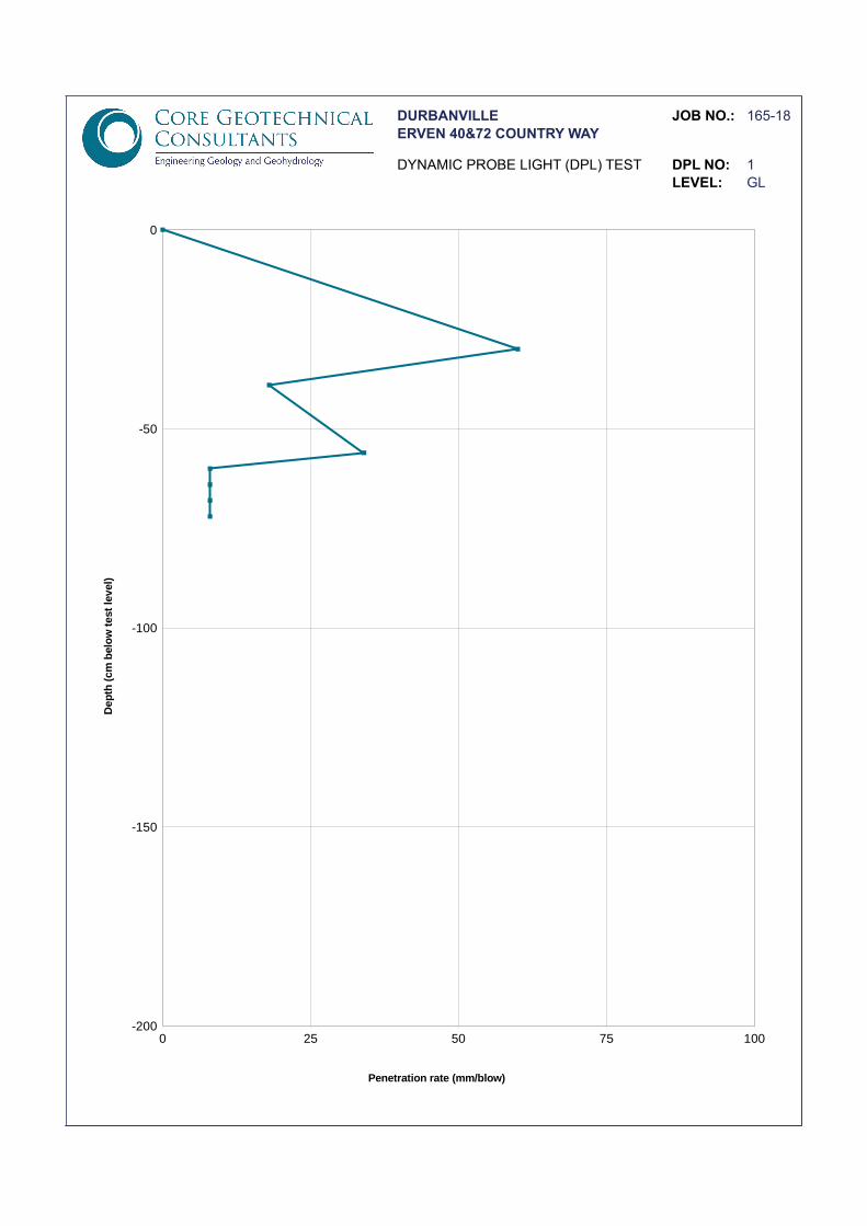
DURBANVILLE JOB NO.: 165-18ERVEN 40&72 COUNTRY WAY
DYNAMIC PROBE LIGHT (DPL) TEST DPL NO: 1LEVEL: GL
0 25 50 75 100-200
-150
-100
-50
0
Penetration rate (mm/blow)
Dep
th (
cm b
elo
w t
est
leve
l)
DURBANVILLE JOB NO.: 165-18ERVEN 40&72 COUNTRY WAY
DYNAMIC PROBE LIGHT (DPL) TEST DPL NO: 2LEVEL: GL
0 25 50 75 100-200
-150
-100
-50
0
Penetration rate (mm/blow)
Dep
th (
cm b
elo
w t
est
leve
l)
DURBANVILLE JOB NO.: 165-18ERVEN 40&72 COUNTRY WAY
DYNAMIC PROBE LIGHT (DPL) TEST DPL NO: 3LEVEL: GL
0 25 50 75 100-200
-150
-100
-50
0
Penetration rate (mm/blow)
Dep
th (
cm b
elo
w t
est
leve
l)
DURBANVILLE JOB NO.: 165-18ERVEN 40&72 COUNTRY WAY
DYNAMIC PROBE LIGHT (DPL) TEST DPL NO: 4LEVEL: GL
0 25 50 75 100-200
-150
-100
-50
0
Penetration rate (mm/blow)
Dep
th (
cm b
elo
w t
est
leve
l)
CLIENT: Core Geotechnical Erf 40872 Durbanville
Postnet Suite 177
Private Bag X3
Plumstead 7801 08-10-2018
ATT: John Yates L181004
dark brown silty sand 31012
TP 1 @ 0.1-0.6m
Percent
Passing
75,00
63,00
53,00 0,0727 18
37,50 0,0370 14
26,50 0,0188 10
19,00 100 0,0098 8
13,20 95 0,0034 5
9,50 87 0,0024 5
6,70 79 0,0014 5
4,75 73
2,36 67
2,00 67 15,7
1,18 64
0,600 60
0,425 57
0,300 51
0,150 35
0,0750 20
S-P
Percentage
27
51
17
5
The above test results are pertinent to the samples received and tested only. For Geoscience:
While the tests are carried out according to recognized standards Geoscience shall not
be liable for erroneous testing or reporting thereof. This report may not be reproduced except in full without prior consent of Geoscience.
Remarks: ConSR22
SIE
VE
SIZ
E (
mm
)
Sieve Analysis Hydrometer Analysis SCS Dispersion Test
Diameter of
particle (mm)
Percentage of
soil suspension
(%)
Diameter of
particle (mm)
Percentage of
soil suspension
(%)
Linear Shrinkage
% SCS Dispersion:
Initial Moisture Content (%) :
pH:
Conductivity mS/m:
MOD AASHTO (Kg/m³)
MOD AASHTO ; C.B.R. :
Atterberg Limits :
Liquid Limit
Plastic Index
C.B.R. @ 93 % Comp.
C.B.R. @ 100% Comp.
C.B.R. @ 98 % Comp.
C.B.R. @ 95 % Comp.
O.M.C. (%)
C.B.R. @ 90 % Comp.
Swell ( max ) %
Tabulated Summary
Gravel : Percentage - 4.75 mm
Sand : Percentage - 4.75mm and + 0.075mm
Silt : Percentage - 0.075mm and + 0.002mm
Clay : Percentage - 0.002mm
CLIENT SAMPLE NO. :
ASTM D422 SIEVE ANALYSIS
POSITION :
PROJECT:
DATE:
REF:
DESCRIPTION : SAMPLE NO. :
0
10
20
30
40
50
60
70
80
90
100
0,001 0,010 0,100 1,000 10,000 100,000
Perc
en
tag
e P
assin
g
Particle Size (mm)
Particle Size Distribution
CLIENT: Core Geotechnical Erf 40872 Durbanville
Postnet Suite 177
Private Bag X3
Plumstead 7801 08-10-2018
ATT: John Yates L181004
olive clay 31013
TP 3 @ 0.6-0.9m
Percent
Passing
75,00
63,00
53,00 0,0592 72
37,50 0,0301 69
26,50 0,0154 64
19,00 100 0,0083 61
13,20 99 0,0029 58
9,50 99 0,0020 56
6,70 96 0,0012 53
4,75 92
2,36 84
2,00 83
1,18 80
0,600 79
0,425 79
0,300 78
0,150 76
0,0750 73
30
14
7,0
Percentage
8
18
17
56
The above test results are pertinent to the samples received and tested only. For Geoscience:
While the tests are carried out according to recognized standards Geoscience shall not
be liable for erroneous testing or reporting thereof. This report may not be reproduced except in full without prior consent of Geoscience.
Remarks: ConSR22
CLIENT SAMPLE NO. :
ASTM D422 SIEVE ANALYSIS
POSITION :
PROJECT:
DATE:
REF:
DESCRIPTION : SAMPLE NO. :
C.B.R. @ 90 % Comp.
Swell ( max ) %
Tabulated Summary
Gravel : Percentage - 4.75 mm
Sand : Percentage - 4.75mm and + 0.075mm
Silt : Percentage - 0.075mm and + 0.002mm
Clay : Percentage - 0.002mm
MOD AASHTO (Kg/m³)
MOD AASHTO ; C.B.R. :
Atterberg Limits :
Liquid Limit
Plastic Index
C.B.R. @ 93 % Comp.
C.B.R. @ 100% Comp.
C.B.R. @ 98 % Comp.
C.B.R. @ 95 % Comp.
O.M.C. (%)
Percentage of
soil suspension
(%)
Linear Shrinkage
% SCS Dispersion:
Initial Moisture Content (%) :
pH:
Conductivity mS/m:
SIE
VE
SIZ
E (
mm
)
Sieve Analysis Hydrometer Analysis SCS Dispersion Test
Diameter of
particle (mm)
Percentage of
soil suspension
(%)
Diameter of
particle (mm)
0
10
20
30
40
50
60
70
80
90
100
0,001 0,010 0,100 1,000 10,000 100,000
Perc
en
tag
e P
assin
g
Particle Size (mm)
Particle Size Distribution
LABORATORY TEST RESULTS
CLIENT : Core Geotechnical
PROJECT NAME : Erf 40872 Durbanville admin only
JOB NO : L181004
SAMPLE NO : 31013
COMPACTION MOULD PERMEAMETER
POSITION : Clay Borrow Area
SOIL DESCRIPTION : dark red sandy clay
PERMEANT USED : TAP WATER
SAMPLE DATA ACTUAL DATA
Bulk Density kg/m3
1911 Mould Number P4
Moisture content of sample % 21,10 Mass of Mould g 4724
Percent of Bulk Density % 100,00 Mass of Mould and wet soil g 9394
Dry density of soil required kg/m3
1911,00 Mass of wet soil g 4670
Moisture content of sample % 21,10 moisture content % 21,10
Length of sample mm 125,00 Bulk Density kg/m3
2114,14
Diameter of sample mm 150,00 Dry Density kg/m3
1745,78
Area of sample mm2
17671,46 Percentage Proctor % 91,35
Volume of sample mm3
2208932,33
Mass of dry soil required g 4221,27 Standpipe dia mm 3,75
Mass of wet soil required g 5111,96 Standpipe area mm2
11,04
TEST READINGS CALCULATIONS FOR FALLING HEAD
Start Test End Test Comments Elapsed COEFFICIENT
Test Height Time Height Time Log H1/H2 Time OF PERMEABILITY
mm min sec mm min sec mm sec m/s
1 2200 2150 44 46 0,0100 2686,00 6,68E-10
2 2200 2190 192 6 0,0020 11526,00 3,08E-11
3 2200 2130 201 56 0,0140 12116,00 2,08E-10
4
Number of tests = 3 AVERAGE = 2,27E-10 m/s
AVERAGE = 2,27E-08 cm/s
Notes :
CLIENT: Core Geotechnical Erf 40872 Durbanville
Postnet Suite 177
Private Bag X3
Plumstead 7801 08-10-2018
ATT: John Yates L181004
dark brown silty sand 31014
TP 4 @ 1.5-2.3m
Percent
Passing
75,00
63,00
53,00 0,0720 30
37,50 0,0366 24
26,50 0,0185 21
19,00 0,0097 18
13,20 0,0034 11
9,50 0,0024 9
6,70 100 0,0014 8
4,75 99
2,36 99
2,00 99 23,4
1,18 98
0,600 94
0,425 89
0,300 80
0,150 55
0,0750 31
S-P
Percentage
1
68
21
10
The above test results are pertinent to the samples received and tested only. For Geoscience:
While the tests are carried out according to recognized standards Geoscience shall not
be liable for erroneous testing or reporting thereof. This report may not be reproduced except in full without prior consent of Geoscience.
Remarks: ConSR22
CLIENT SAMPLE NO. :
ASTM D422 SIEVE ANALYSIS
POSITION :
PROJECT:
DATE:
REF:
DESCRIPTION : SAMPLE NO. :
C.B.R. @ 90 % Comp.
Swell ( max ) %
Tabulated Summary
Gravel : Percentage - 4.75 mm
Sand : Percentage - 4.75mm and + 0.075mm
Silt : Percentage - 0.075mm and + 0.002mm
Clay : Percentage - 0.002mm
MOD AASHTO (Kg/m³)
MOD AASHTO ; C.B.R. :
Atterberg Limits :
Liquid Limit
Plastic Index
C.B.R. @ 93 % Comp.
C.B.R. @ 100% Comp.
C.B.R. @ 98 % Comp.
C.B.R. @ 95 % Comp.
O.M.C. (%)
Percentage of
soil suspension
(%)
Linear Shrinkage
% SCS Dispersion:
Initial Moisture Content (%) :
pH:
Conductivity mS/m:
SIE
VE
SIZ
E (
mm
)
Sieve Analysis Hydrometer Analysis SCS Dispersion Test
Diameter of
particle (mm)
Percentage of
soil suspension
(%)
Diameter of
particle (mm)
0
10
20
30
40
50
60
70
80
90
100
0,001 0,010 0,100 1,000 10,000 100,000
Perc
en
tag
e P
assin
g
Particle Size (mm)
Particle Size Distribution
DETERMINATION OF BULK DENSITY (ASTM D1188)
PROJECT: Erf 40872 Durbanville
PROJECT NO.: L18004
CLIENT: Core Geotechnical
ATT: John Yates
Sample Position Description Bulk Moisture DryNumber Density Content % Density31013 TP 3 @ 0,6-0,9m 1911 21,1 1578
Bradford Close, Airport Industria, P.O Box 288 Parow 7499
Telephone: (021) 9341114 Fax: (021) 9348161