atv accessories - swisher
TRANSCRIPT

ATV ACCESSORIES
1602 CORPORATE DRIVE PO BOX 67 WARRENSBURG, MISSOURI 64093 PH 660. 747. 8183 FAX 660. 747. 8650
swisherinc.com
MANUFACTURING QUALITY LAWN CARE EQUIPMENT SINCE 1945
Owner’s Manual Model Numbers
ReceiverHitch10260
Plow Blade2140
IMPORTANTRead and follow all Safety Precautions and Instructions
Before Operating this Equipment.
Made In The
USA
ASSEMBLY OPERATION
SERVICE AND ADJUSTMENT REPAIR PARTS
REV. 07-1492142
Sold as Separate Pieces!!!!

LIMITED WARRANTY The manufacturer’s warranty to the original consumer purchaser is: This product is free from defects in materials and workmanship for a period of one (1) year from the date of purchase by the original consumer purchaser. We will repair or replace, at our discretion, parts found to be defective due to materials or workmanship. This warranty is subject to the following limitations and exclusions: 1) Commercial Use The warranty period for any product used for commercial or rental
is limited to ninety (90) days from the date of original purchase. 2) Limitations This warranty applies only to products which have been properly
assembled, adjusted, and operated in accordance with the instructions contained within this manual. This warranty does not apply to any product of Swisher Mower Co., Inc., that has been subject to alteration, misuse, abuse, improper assembly or installation, or shipping damage.
3) Exclusions Excluded from this warranty are normal wear, normal adjustments,
and normal maintenance. In the event you have a claim under this warranty, you must return the product to an authorized service dealer. All transportation charges, damage, or loss incurred during transportation of parts submitted for replacement or repair under this warranty shall be borne by the purchaser. Should you have any questions concerning this warranty, please contact us toll-free at 1-800-222-8183. The model number, serial number, date of purchase, and the name of the authorized Swisher dealer from whom you purchased the mower will be needed before any warranty claim can be processed. THIS WARRANTY DOES NOT APPLY TO ANY INCIDENTAL OR CONSEQUENTIAL DAMAGES AND ANY IMPLIED WARRANTIES ARE LIMITED TO THE SAME TIME PERIODS STATED HEREIN FOR ALL EXPRESSED WARRANTIES. Some states do not allow the limitation of consequential damages or limitations on how long an implied warranty may last, so the above limitations or exclusions may not apply to you. This warranty gives you specific legal rights and you may have other rights, which vary from state-to-state. This is a limited warranty as defined by the Magnuson-Moss Act of 1975.

SAFETY PRECAUTIONS & DECALS
• Read the manual. Learn to operate this machine safely.
• Keep the operating speed LOW!!!!! • Allow only responsible adults who are familiar with these instructions to
operate this machine. Never allow children to operate this machine.
• Be sure the area is clear of other people before operating. Children are often attracted to the machine and the operating activity. Never assume that children will remain where you last saw them. Keep children under the watchful care of another responsible adult.
• Watch for traffic when operating near or crossing roadways.
• Do not operate the attachment if it has been dropped or damaged in any
manner. Repair as necessary.
• Dress properly. Do not operate when barefoot or wearing open sandals.
• Do not operate the machine while under the influence of alcohol or drugs.
• Never tamper with safety devices. Check their proper operation regularly.
This Safety Alert Symbol indicates important messages in this manual. When you see this symbol, carefully read the message that follows and be alert to the possibility of personal injury.
Read this manual completely. Failure to observe the following safety instructions could result in serious injury or death.

• Operate attachments up and down slopes. There is significant risk of overturns when operating across slopes.
• Stop and inspect the equipment if you strike an object. Repair, if necessary,
before restarting.
• Never make adjustments or repairs with the engine running.
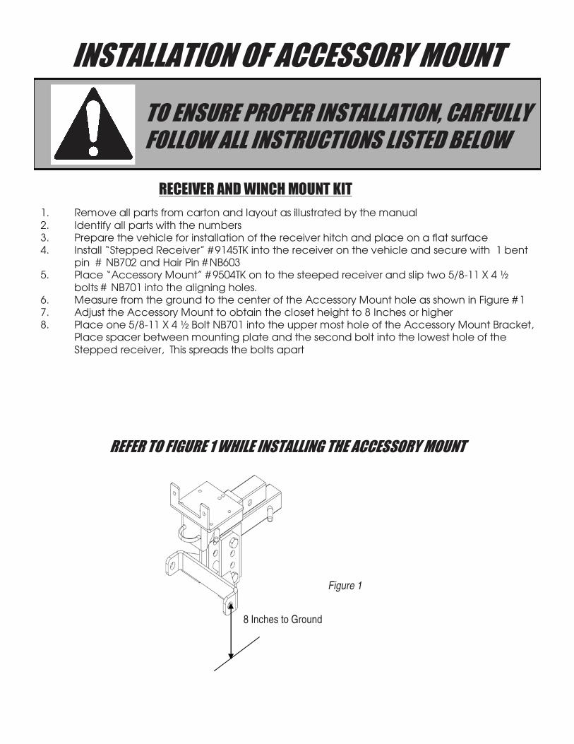
INSTALLATION OF ACCESSORY MOUNT
TO ENSURE PROPER INSTALLATION, CARFULLY FOLLOW ALL INSTRUCTIONS LISTED BELOW
REFER TO FIGURE 1 WHILE INSTALLING THE ACCESSORY MOUNT
RECEIVER AND WINCH MOUNT KIT
1. Remove all parts from carton and layout as illustrated by the manual
2. Identify all parts with the numbers3. Prepare the vehicle for installation of the receiver hitch and place on a flat surface4. Install “Stepped Receiver” # 9145TK into the receiver on the vehicle and secure with 1 bent
pin # NB702 and Hair Pin # NB6035. Place “Accessory Mount” # 9504TK on to the steeped receiver and slip two 5/8-11 X 4 ½
bolts # NB701 into the aligning holes.6. Measure from the ground to the center of the Accessory Mount hole as shown in Figure # 17. Adjust the Accessory Mount to obtain the closet height to 8 Inches or higher8. Place one 5/8-11 X 4 ½ Bolt NB701 into the upper most hole of the Accessory Mount Bracket,
Place spacer between mounting plate and the second bolt into the lowest hole of the
Stepped receiver, This spreads the bolts apart
Figure 1
8 Inches to Ground

INSTALLING WINCH TO WINCH MOUNTINSTALLING WINCH TO WINCH MOUNTINSTALLING WINCH TO WINCH MOUNTINSTALLING WINCH TO WINCH MOUNT
1. The Winch and Roller Fairlead are supplied by Other parties, We have made every
attempt to provide the proper mounting holes to cover all of the popular models2. Install the winch to the Winch manufactures specifications.3. Install the “Roller Fairlead” to the mount with the bolts coming from the back. This
gives the maximum amount of room for the winch.4. After the winch and roller fairlead have been mounted and tightened securely ,
Install the mount into the receiver to the rearward most position and secure with Bent Pin # NB702. The rearward position effects the angle and position of the cable on the accessory.
Winch And Roller
Supplied by others
Insert
Figure 2

Receiver Hitch Model # 9146
ITEM NO. PART NO. DESCRIPTION
1 9504TK Accessory Mount
2 9145TK Stepped Receiver
3 9150TK Winch Mount
4 NB-701 5/8-11 X 4 1/2 Hex Hd Bolt
5 NB-702 5/8 x 3 Bent Pin
6 NB-561 5/8-11 Lock Nut
7 9147TK Spacer
8 NB603 # 10 Hair Pin
Winch And Roller
Supplied by others
1
4
5
6
73
2
8

INSTALLATION OF PLOW ATTACHMENT
TO ENSURE PROPER INSTALLATION, CARFULLY FOLLOW ALL INSTRUCTIONS LISTED BELOW
REFER TO FIGURE 6 WHILE INSTALLING THE ACCESSORY MOUNT
1. Unpack parts and make sure all are included. If they are not contact the dealer where the Swisher Plow was purchased.
2. Locate the Pivot Plate(1) and assemble to the blade using two ½-13 X 2” bolts(12) and corresponding Nyloc nuts(13) and washers(18) The washers are needed since this connection is a pivot point.
3. Assemble the stop blocks (3) to the pivot plate weldment using two ½-13 X 2” bolts(12) and corresponding Nyloc nuts(13).
4. Attach two eye-bolts (6) into the holes at the top of the blade. Secure them with nuts(14)(7) and washers(15). Place plastic caps(17) over the remaining threads of the eye-bolts.
5. Attach the tilt springs (16) to the eye-bolts and to the tabs on the Pivot Plate weldment(1). See PointA Fig. 6
6. Connect the skids (5) through the channels on the outer edges of the blade. One skid on each side. Adjust their height and pin with (10) and (11).
The next steps need to be done in sequence:1. Slide the Plow Mount(19) into Pivot Plate and bolt the two together with bolt(23) and nut(13).2. Assemble Lock Arm(29) as shown in the detail. Make sure the tail of the spring (25) is secured into the
bent washer that is welded onto the Plow Mount(19) See figure 6A. The Lock Arm (29) should be able to pivot freely when assembled.
3. Bolt “U” shaped Plow Mount bracket (22) onto Plow Mount(19) with support plate (28) under Plow Mount(19). Use two Nyloc nuts(7) and two bolts(31). Secure tightly.
4. Insert bolt (27) into the “U” bracket(22) and secure with nut (13). This is where you will attach your winch or manual lift pulley, sold separately. With your Swisher ATV Accessory Mount already installed, attach the plow to it using plow mount pin (20) and 2 click pins(21).
5. Attach red rope(30) to eyelet on trigger(30) and loop over front of ATV so it can be reached by the operator.
6. Read Dangers on the back of the Swisher Plow and consult this manual.7. It would be wise to become familiar with your plow using a slower speed.
Tail of Spring 25
Figure 3
25
18
23 24
1
2919
28
Top of weldment is
removed for clarity

PLOW ATTACHMENT ASSEMBLY
ITEM
NO.QTY. PART
NO.DESCRIPTION ITEM
NO.QTY PART
NO. DESCRIPTION
1 1 2323TK Pivot Weldment 17 2 AS-125 Round Vinyl Cap
2 1 2139TK 62" Rolled Blade Weldment 18 6 NB-177 1/2 NR Mach. Bushing
3 2 2331TK Tilt Block 19 1 2588TK Plow Mount
4 1 2099TK Cut Edge 20 1 2642TK Plow Mount Pin
5 2 10068TK Skid 21 2 NB-506 3/16 Click Pin
6 2 NB-635 3/8-16 X 3 Turned Eye Bolt 22 1 2327TK Plow Mount Bracket
7 4 NB-182 3/8-16 Nyloc Nut 23 1 TR150W Washer
8 9 10216 5/16-18 X 3/4 Carriage Bolt 24 1 2336 Pivot Spring
9 9 NB-170 5/16-18 Serrated Flange Nut 25 4 NB-121 1/2-13 2 Way Jam Lock Nut
10 2 NB-300 Clevis Pin Std ZP 3/8 26 1 NB-131 1/2-13 X 3 Hex Bolt
11 2 NB-127 # 3 Hair Pin 27 1 2310TK Plow Bracket Support
12 4 NB-509 1/2-13 X 2 Hex Bolt 28 2 NB-577 1/2-13 X 3 1/2 Hex Bolt
13 6 NB-281 1/2-13 Nyloc Nut 29 1 2319TK Lock Arm
14 2 NB-212 3/8-16 Hex Nut 30 2 NB-649 3/8-16 X 3 1/2 Hex Bolt
15 2 NB-272 3/8 SAE Washer 31 1 H9B Rope (Not Shown)
16 2 2335 Tilt Spring 32 1 H7K Knob (Not Shown)
7
FIGURE 2
See detail on Page 8
4
8
9
5
1011
12
18
13
16
6
14
15
7
17
12 18 13
3
1
2
713
22
2628
13
19
28
302720
21
21

ADJUSTMENT AND OPERATION
1. AFTER INSTALLING YOUR PLOW, MAKE SURE THE ROPE IS TIED TO YOUR ATV SOMEWHERE
YOU CAN GRAB WHILE OPERATING. 2. THE ROPE SHOULD NOT BE TIGHT BUT NOT TOO LOOSE TO AVOID ACCIDENTAL RELEASE OF
THE LOCK ARM OR TANGLING. 3. IF YOU NEED TO CHANGE THE BLADE ANGLE WHILE OPERATING, COME TO A STOP, PULL THE
ROPE AND RELEASE THE LOCK ARM. 4. SLOWLY DRIVE THE PLOW INTO A SNOW BANK AT AN ANGLE TO MOVE THE BLADE. 5. WHEN THE PROPER ANGLE IS ACHIEVED RELEASE THE ROPE, LOCKING THE BLADE IN PLACE.
6. ADJUST THE SKIDS TO PROVIDE THE PROPER CLEARENCE. WHEN REMOVING SNOW FROM A GRAVEL DRIVE, YOU MAY WANT THE BLADE UP TO PREVENT REMOVING MORE GRAVEL THAN DESIRED
7. THE CUT EDGE WILL WEAR DOWN AS IT IS USED. THE CUT EDGE IS DESIGNED TO BE TURNED
OVER TO EXTEND THE LIFE.8. THE BLADE HAS TWO SPRINGS WHICH ALLOW THE BLADE TO FLIP OVER WHEN STRIKING
SOMETHING SOLID. THIS IS TO HELP PREVENT DAMAGE TO THE POWER UNIT. DO NOT LOCK THE BLADE IN A FIXED POSITION

NOTES:____________________________________________________________________________________________________________________________________________________________________________________________________________________________________________________________________________________________________________________________________________________________________________________________________________________________________________________________________________________________________________________________________________________________________________________________________________________________________________________________________________________________________________________________________________________________________________________________________________________________________________________________________________________________________________________________________________________________________________________________________________________________________________________________________________________________________________________________________________________________________________________________________________________________________________________________________________________________________________________________________________________________________________________________________________________________________________________________________________________________________________________________________________________________________________________________________________________________________________________________________________________________________________________________________________________________________________________________________________________________________________________________________________________________________________________________________________________________________________________________________________________________________________________________________________________________________________________________________________________________________________________________________________________________________________________________________________________________________________________________________________________________________________________________________________________________________________________________________________________________________________________________________________________________________________________________________________________________________________________________________________________________________________________________________________________________________________________________________________________________________________________________________________________________________________________________________________________________________________________________________________________________________________________________________________________________________________________________________________________

swisherinc.com
MANUFACTURING QUALITY LAWN CARE EQUIPMENT SINCE 1945
WHEN ORDERING PARTS, PLEASE HAVE THEFOLLOWING INFORMATION AVAILABLE:
* PRODUCT – ________________* SERIAL NUMBER - _______________* MODEL NUMBER - _______________
TYPE - _______________* PART NUMBER WITH PAINT CODE
* PART DESCRIPTION
TELEPHONE - 1-800-222-8183FAX - 1-660-747-8650
SWISHER MOWER & MACHINE CO. INC.SWISHER MOWER & MACHINE CO. INC.SWISHER MOWER & MACHINE CO. INC.SWISHER MOWER & MACHINE CO. INC.1602 CORPORATE DRIVE
P.O. BOX 67WARRENSBURG, MO 64093
ATV ACCESSORIES
Owner’s Manual Model Numbers
ReceiverHitch10260
Plow Blade2140
IMPORTANTRead and follow all Safety Precautions and Instructions
Before Operating this Equipment.