atv sprayer - demco products · • give sprayer a visual inspection for any loose bolts, worn...
TRANSCRIPT

AS20018, Rev 505/16
Atv SpRAyeR25 Gallon
Page 2 AS20018
Thank you for purchasing a Demco sprayer. We feel you have made a wise choice and hope you are completely satisfied with your new sprayer. If you have any questions regarding the applications of certain solutions or chemicals, contact your chemical supplier and follow chemical manufacturer recommendations as well as all licensing and use restrictions or regulations.
1. Unless otherwise specified, high-strength (grade5) (3 radial-line head markings) hex head bolts are used throughout assembly of this sprayer.
2. Whenever terms “LEFT” and “RIGHT” are used in this manual it means from a position behind sprayer and facing forward.
3. When placing a parts order, refer to this manual for proper part numbers and place order by PART NO., DESCRIPTION, and COLOR.
WARRANty pOLICy, OpeRAtOR MANUALS, pARtS MANUALS & ReGIStRAtION
Go online to www.demco-products.com to review Demco warranty policies, operator manuals and register your Demco product.
INtRODUCtION
Chemicals are dangerous. Know exactly what you’re going to do and what is going to happen before attempting to work with these products. Improper selection or use can injure people, animals, plants and soil.
Always wear protective clothing such as coveralls, goggles and gloves when work-ing with chemicals or sprayer.
Be sure to dispose of all unused chemicals or solutions in a proper and ecologically sound manner.
WARNING: TO AvOID PERSONAL INjuRy OR DEATH, OBSERvE FOLLOWING INSTRuCTIONS:
GeNeRAL INFORMAtION
Introduction and Warranty Policy & Registration ......................................................2 General Information .....................................................................................................2Safety You Can Live With .......................................................................................... 4-10Safety Signs ...................................................................................................................5Safety Sign Locations....................................................................................................5Bolt Torque ...................................................................................................................11 25 Gallon Parts Breakdown and Assembly Instructions .......................................12-13 Main Plumbing Parts Breakdown and List ................................................................14 Add-on 25 Gallon Tank Parts Breakdown and List ...................................................15 Boom Mounting Instructions ......................................................................................16 Calibration Instructions ............................................................................................17-19 Pressure Relief Parts Breakdown and List .................................................................20 Hand Wand Parts Breakdown .....................................................................................20 5 GPM Pump Parts Breakdown and List ....................................................................21 Sprayer Checklist .........................................................................................................22
tABLe OF CONteNtS

Page 3 AS20018
TAKE NOTE! THIS SAFETy ALERT SyMBOL FOuND THROuGHOuT THISMANuAL IS uSED TO CALL yOuR ATTENTION TO INSTRuCTIONS INvOLvING yOuR PERSONAL SAFETy AND SAFETy OF OTHERS. FAILuRE TO FOLLOW THESE INSTRuCTIONS CAN RESuLT IN INjuRy OR DEATH!
THIS SyMBOL MEANS
ATTENTION
BECOME ALERT
yOuR SAFETy IS INvOLvED!
DANGeR: Indicates an imminently hazardous situation that, if not avoided, will result in death or serious injury. This signal word is to be limited to most extreme situations typically for machine components which, for functional purposes, cannot be guarded.
WARNING: Indicates a potentially hazardous situation that, if not avoided, could result in death or serious injury, and includes hazards that are exposed when guards are removed. It may also be used to alert against unsafe practices.
CAUtION: Indicates a potentially hazardous situation that, if not avoided, may result in minor or moderate injury. It may also be used to alert against unsafe practices.
If you have questions not answered in this manual, require additional copies, or if your manual is damaged, please contact your dealer or DEMCO, 4010 320th Street, Boyden, IA 51234
ph: (712) 725-2311 or Toll Free: 1-800-543-3626 Fax: (712) 725-2380 or 1-800-845-6420http://www.demco-products.com
SIGNAL WORDS: This manual uses the following signal words--DANGER, WARNING, and CAuTION-- with safety messages. The appropriate signal word has been selected using the following guidelines.
SAFety

Page 4 AS20018
Every year many accidents occur which could be avoided by a few seconds of thought and more careful approach to handling equipment. You, the operator, can avoid accidents by observing precautions in this section. To avoid personal injury, study precautions and insist those working with you, or you yourself, follow them.
In order to provide a better view, certain illustrations in this manual may show an assembly with a safety shield removed. However, sprayer should never be operated in this condition. Keep all shields in place. If shield removal becomes necessary for repairs, replace shield prior to use.
Replace any caution, warning, danger or instruction safety decal that is not readable or is missing. Location of such decals is indicated in this booklet.
Do not attempt to operate this sprayer under the influence of alcohol or drugs.
Review safety instructions with all users.
Operator should be a responsible adult. DO NOT ALLOW PERSONS TO OPERATE OR ASSEMBLE THIS SPRAyER uNTIL THEy HAvE DEvELOPED A THOROuGH uNDERSTANDING OF SAFETy PRECAuTIONS AND HOW IT WORKS.
To prevent injury or death, use a tractor equipped with a roll over protective system (ROPS). Do not paint over, remove, or deface any safety signs or warning decals on your sprayer. Observe all safety signs and practice instructions on them.
Never exceed limits of sprayer. If its ability to do a job, or to do so safely is in questionDON’T TRy IT.
It is the responsibility of operator to know lighting and marking requirements of local highway authorities and to install and maintain equipment to provide compliance with regulations. Add extra lights when transporting at night or during periods of limited visibility.
Lighting kits are available from your dealer or manufacturer.
SAFETy...yOu CAN LIvE WITH IT
SAFety
eqUIpMeNt SAFety GUIDeLINeS
LIGhtING AND MARkING

Page 5 AS20018
Types of safety sign and locations on equipment are shown in illustration below. Good safety requires that you familiarize yourself with various safety signs, type of warning, and area or particular function related to that area, that requires your SAFETY AWARENESS.
1. AA21012 2 “Demco” Decal 2. AB21014 1 Warning Decal 3. AA21002 2 “Boyden, Iowa” Decal
REF. PART NO. NO. QTy. DESCRIPTION
Please order replacement parts by PART NO. and DESCRIPTION.
3
2
3
2
1
1
AA21012
SAFety SIGN LOCAtIONS
SAFety

Page 6 AS20018
• Keepsafetysignscleanandlegibleatalltimes.
• Replacesafetysignsthataremissingorhavebecomeillegible.
• Replacementpartsthatdisplayedasafetysignshouldalsodisplaycurrentsign.
• Safetysignsareavailablefromyourdistributor,dealerpartsdepartment,or manufacturer.How to install safety signs:
• Besureinstallationareaiscleananddry.
• Decideonexactpositionbeforeyouremovebackingpaper.
• Removesmallestportionofsplitbackingpaper. • Aligndecaloverspecifiedareaandcarefullypresssmallportionwith exposed sticky backing in place.
• Slowlypeelbackremainingpaperandcarefullysmoothremainingportionofdecalintoplace.
• Smallairpocketscanbepiercedwithapinandsmoothedoutusingpieceofdecalbackingpaper.
• Failuretofollowproperprocedureswhenmountingtireonrimcanproducean explosion resulting in serious injury or death.
• Donotattempttomounttireunlessyouhaveproperequipmentandexperience.
• Inflatingorservicingtirescanbedangerous.Wheneverpossible,trainedpersonnelshouldbecalled to service or mount tires.
• Alwaysorderandinstalltiresandwheelswithappropriatetypeandloadcapacityto meet or exceed anticipated weight to be placed on sprayer.
Your best assurance against accidents is a careful and responsible operator. If there is any portion of this manual or function you do not understand, contact your local authorized dealer or manufacturer.
• Carefullystudyandunderstandthismanual.
• Donotwearloose-fittingclothingwhichmaycatchinmovingparts.
• Alwayswearprotectiveclothingandsubstantialshoes.
• Itisrecommendedthatsuitablehearingandeyeprotectionbeworn.
• Operatormaycomeincontactwithcertainmaterialswhichmayrequirespecificsafetyequipmentrelativeto handling of such materials. (Examples: extremely dusty, molds, fungus, bulk fertilizers, etc.)
SAFety SIGN CARe
tIRe SAFety
ReMeMBeR
BeFORe OpeRAtION:
SAFety
Page 7 AS20018
• Keepwheelandlugnutstightenedtospecifiedtorque.
• Assurethatagriculturalimplementtiresareinflatedevenly.
• Givesprayeravisualinspectionforanyloosebolts,wornparts,orcrackedwelds,and make necessary repairs. Follow maintenance safety instructions included in this manual.
• Besuretherearenotoolslyingonorinequipment.
• Donotusethesprayeruntilyouaresurethatareaisclear,especiallyaroundchildrenandanimals.
• Don’thurrylearningprocessortakesprayerforgranted.Easeintoitandbecomefamiliarwithyournewequipment.
• Practiceoperationofyoursprayeranditsattachments.Completelyfamiliarizeyourselfandotheroperatorswith its operation before using.
• UseatractorequippedwithRollOverProtectionSystem(ROPS)andfastenyourseatbeltpriortostartingengine.
• ManufacturerdoesnotrecommendusageoftractorwithROPSremoved.
• Movetractorwheelstowidestrecommendedsettingstoincreasestability.
• Donotallowanyonetostandbetweentongueorhitchandtowingunitwhenbackinguptoequipment.
SAFety
DURING OpeRAtION
• Bewareofbystanders,PARTICuLARLy CHILDREN! Always look around to make sure that it is safe to start engine of towing vehicle or move sprayer. This is particularly important with higher noise levels and quiet cabs, as you may not hear people shouting.
• NO PASSENGERS ALLOWED - Do not carry passengers anywhere on or in tractor or sprayer.
• Keephandsandclothingclearofmovingparts.
• Donotclean,lubricate,oradjustyoursprayerwhileitismoving.
• Whenhaltingoperation,evenperiodically,set tractoror towingvehiclesbrakes,disengagePTO,shutoffengine, and remove ignition key.
• Beespeciallyobservantofoperatingareaandterrain.Watchforholes,rocks,orotherhiddenhazards.Alwaysinspect area prior to operation.
- DO NOT operate near edge of drop-off or banks.
- DO NOT operate on steep slopes as overturn may result.
- Operate up and down (not across) intermediate slopes. Avoid sudden starts and stops.
• Pickthemostlevelpossibleroutewhentransportingacrossfields.Avoidedgesofditches,gullies,andsteephillsides.
• Beextracarefulwhenworkingoninclines.
Page 8 AS20018
• Followingoperation,orwhenunhitching,stoptractorortowingunit,setbrakes,disengagePTOandall power drives, shut off engine and remove ignition key.
• Storesprayerinanareaawayfromhumanactivity.
• Donotparksprayerwhereitwillbeexposedtolivestockforlongperiodsoftime.Damageandlivestock injury could result.
• Donotpermitchildrentoplayonoraroundthestoredsprayer.
• Makesureallparkedmachinesareonahard,levelsurfaceandengageallsafetydevices.
• Wheelchocksmaybeneededtopreventunitfromrolling.
• Maneuvertractorortowingvehicleatsafespeeds.
• Avoidoverheadwiresorotherobstacles.Contactwithoverheadlinescouldcauseseriousinjuryordeath.
• Avoidloosegravel,rocks,andholes;theycanbedangerousforequipmentoperationormovement.
• Allowforunitlengthwhenmakingturns.
• Donotwalkorworkunderraisedcomponentsorattachmentsunlesssecurelypositionedandblocked.
• Keepallbystanders,pets,andlivestockclearofworkarea.
• Operatetowingvehiclefromoperatorsseatonly.
• Neverstandalongsideofunitwithenginerunningorattempttostartengineand/oroperatemachinewhilestanding alongside of unit.
• Neverleaverunningequipmentunattended.
• Asaprecaution,alwaysrecheckhardwareonequipmentfollowingevery100hoursof operation. Correct all problems. Follow maintenance safety procedures.
SAFety
FOLLOWING OpeRAtION
hIGhWAy AND tRANSpORt OpeRAtIONS
• SAFETYCHAINS:If equipment is going to be transported on a public highway, always follow state and local regu-lations regarding safety chains and auxiliary lighting. Be sure to check with local law enforcement agencies for your own particular regulations. If required safety chains should be obtained and installed. Only safety chains (not elastic or nylon/plastic tow straps) should be used to retain connection between towing and towed machines in event of sepa-ration of primary attaching system. Use a high strength, appropriately sized hitch pin with a mechanical retainer and attach safety chains. Criss cross chains under tongue and secure to draw bar cage, mounting loops, or bumper frame.

Page 9 AS20018
• Adoptsafedrivingpractices:
- Keep brake pedals latched together at all times. NEvER uSE INDEPENDENT BRAKING WITH SPRAyER IN TOW. LOSS OF CONTROL OR uPSET MAy RESuLT.
- Always drive at a safe speed relative to local conditions and ensure that your speed is low enough for an emergency stop. Keep speed to a minimum.
- Reduce speed prior to turns to avoid risk of overturning.
- Always keep tractor or towing unit in gear to provide engine braking when going downhill. Do not coast.
- Do not drink and drive!
• Complywithstateandlocallawsgoverninghighwaysafetyandmovementoffarmmachineryon public roads.
• Useapprovedaccessorylightingflagsandnecessarywarningdevicestoprotectoperatorsof other vehicles on highway during transport. Various safety lights and devices are available from your dealer.
• Useofflashingamberlightsisacceptableinmostlocalities.However,somelocalitiesprohibit their use. Local laws should be checked for all highway lighting and marking requirements.
• Whendrivingtractorandsprayerunder20mph(40kph)dayornight,useflashingamberwarning lights and a slow moving vehicle (SMV) identification emblem.
• Planyourroutetoavoidheavytraffic.
• Beasafeandcourteousdriver.Alwaysyieldtooncomingtrafficinallsituations,includingnarrow bridges, intersections, etc.
• Beobservantofbridgeloadratings.Donotcrossbridgesratedlowerthangrossweightofunit you are operating.
SAFety
• Watchforobstructionsoverheadandsidetosidewhiletransporting.
• Alwaysoperateequipmentinapositiontoprovidemaximumvisibilityatalltimes.Makeallowancesfor increased length and weight of sprayer when making turns, or stopping.
peRFORMING MAINteNANCe
• Goodmaintenanceisyourresponsibility.Poormaintenanceisaninvitationtotrouble.
• Makesurethereisplentyofventilation.Neveroperateengineoftowingvehicleinaclosedbuilding. Exhaust fumes may cause asphyxiation.
• Beforeworkingonthismachine,stoptowingvehicle,setbrakes,disengagePTOandallpowerdrives, shut off engine and remove ignition key.
• Becertainallmovingpartsandattachmentshavecometoacompletestopbeforeattemptingto perform maintenance.
• Always use a safety support and block wheels. Never use a jack to support machine.

Page 10 AS20018
• Alwaysusepropertoolsorequipmentforjobathand.
• Useextremecautionwhenmakingadjustments.
• Followtorquechartinthismanualwhentighteningboltsandnuts.
• Neveruseyourhandstolocateahydraulicleakonattachments.Useasmallpieceofcardboardorwood. Hydraulic fluid escaping under pressure can penetrate skin.
• Openingsinskinandminorcutsaresusceptibletoinfectionfromhydraulicfluid. Without immediate medical treatment, serious infection and reactions can occur.
• Whendisconnectinghydrauliclines,shutoffhydraulicsupplyandrelieveallhydraulicpressure.
• Replaceall shields and guards after servicing and before moving.
• Afterservicing,besurealltools,partsandserviceequipmentareremoved.
• Donotallowgreaseoroiltobuilduponanystepsorplatform.
• Whenreplacingboltsrefertoownersmanual.
• Refertobolttorquechartforheadidentificationmarking.
• Wherereplacementpartsarenecessaryforperiodicmaintenanceandservicing,genuinefactory replacement parts must be used to restore your equipment to original specifications. Manufacturer will not claim responsibility for use of unapproved parts or accessories and other damages as a result of their use.
• Ifequipmenthasbeenalteredinanywayfromoriginaldesign,manufacturerdoesnotacceptanyliability for injury or warranty.
• Afireextinguisherandfirstaidkitshouldbekeptreadilyaccessiblewhileperformingmaintenanceonthis equipment.
SAFety

Page 11 AS20018
BOLt tORqUe
Torque figures indicated are valid for non-greased or non-oiled threads and heads unless otherwise specified. Therefore, do not grease or oil bolts or capscrews unless otherwise specified in this manual. When using locking elements, increase torque values by 5%.
* GRADE or CLASS value for bolts and capscrews are identified by their head markings.
BOLt tORqUe DAtA FOR StANDARD NUtS, BOLtS, AND CApSCReWS.
Tighten all bolts to torques specified in chart unless otherwise noted. Check tightness of bolts periodically, using bolt chart as guide. Replace hardware with same grade bolt.
NOTE: Unless otherwise specified, high-strength Grade 5 hex bolts are used throughout assembly of equipment.
tORqUe SpeCIFICAtION
Bolt torque for Standard bolts *
“A”GRADe 2 GRADe 5 GRADe 8
lb-ft (N.m) lb-ft (N.m) lb-ft (N.m)
1/4” 6 (8) 9 (12) 12 (16)
5/16” 10 (13) 18 (25) 25 (35)
3/8” 20 (27) 30 (40) 45 (60)
7/16” 30 (40) 50 (70) 80 (110)
1/2” 45 (60) 75 (100) 115 (155)
9/16” 70 (95) 115 (155) 165 (220)
5/8” 95 (130) 150 (200) 225 (300)
3/4” 165 (225) 290 (390) 400 (540)
7/8” 170 (230) 420 (570) 650 (880)
1” 225 (300) 630 (850) 970 (1310)
Bolt torque for Metric bolts *
“A”CLASS 8.8 CLASS 9.8 CLASS 10.9
lb-ft (N.m) lb-ft (N.m) lb-ft (N.m)
6 9 (13) 10 (14) 13 (17)
7 15 (21) 18 (24) 21 (29)
8 23 (31) 25 (34) 31 (42)
10 45 (61) 50 (68) 61 (83)
12 78 (106) 88 (118) 106 (144)
14 125 (169) 140 (189) 170 (230)
16 194 (263) 216 (293) 263 (357)
18 268 (363) -- -- 364 (493)
20 378 (513) -- -- 515 (689)
22 516 (699) -- -- 702 (952)
24 654 (886) -- -- 890 (1206)

Page 12 AS20018
NOTE: Racks on ATv’s may vary according to make and model.
CAuTION: Follow manufacturer’s recommendations for rack weight ratings.
15
1614
1012
4
6
2
3
7
5
17
1
14
8
6
3
9
18
19
21
4
151617
20
11
13
21 21
21
22
23 11
25
Negative Wire
Positive Wire
Positive Wire
24
21
25 GALLON
pARtS BReAkDOWN

Page 13 AS20018
REF. PART REQ’D NO. NO. QTy. DESCRIPTION
Please order replacement parts by PART NO. and DESCRIPTION.
1. Start by threading a BEL1212 (#20) into the fitting on the bottom of the tank.
2. Thread two 3/8” x 3/4” Set Screws (#14) into the weldnuts on the frame. Make sure you can still get the boom mounts into the tubes. Next fasten the tank (#1) to the skid (#2) using six 5/16” x 3/4” hex head bolts (#15), six 5/16” spring lock washers (#16), and six 5/16” flat washers (#17).
3. Next mount the pump (#7) to the pump mount (#5) using four #10 UNC x 1” slotted Truss head bolts (#4), four #10 Flat Washers (#21), and four #10 UNC Hex Nuts (#19). Mount this assembly to the top of the tank using four #10 UNC x 3/4” slotted round head bolts (#18) and four #10 Flat Washers (#21).
4. Place the tank and skid on the rear rack of the ATV. Make sure that the skid is as far back as possible without causing damage to the fitting in the bottom of the tank. Secure the sprayer to the rack using the two straps and ratchets (#3). Loop the hook end of the straps around a bar of the rack and secure them on the frame. Then run the strap around the top of the tank. Use the ratchet to tighten as needed.
5. Insert the two boom mounts (#6) and secure into place with the two 3/8” x 3/4” Set Screws (#14).
6. Mount Switch Bracket (#9) in a convenient location using the 1/4” x 1” Bolt (#22) and 1/4” Nylon Insert Locknut (#23) provided.
1. P25 18A 1 25 gal. Tank (1/2” spinweld & Lid incld) 2. 10948-30 1 25 gal. Skid 3. 10984 2 Nylon Strap (Rachets incld) 4. 05483 4 #10 UNC x 1 1/4” Slotted Truss Head Bolt 5. 11012-30 1 Pump Mount / Hand Gun Holder 6. 10950-30 2 Boom Mounts 7. 12981 1 Electric Pump 8. PL5A 1 Replacement Lid (included w/ P25 18 Tank) 9. 04755-95 1 Switch Mount Bracket 10. 04764 1 10’WireHarness 11. 01013 1 Replacement Switch w/nut (incld w/ 04764) 12. 05021 2 Female Bullet Connector (included w/ 04764) 13. 09272 1 Replacement Fuse (included w/ 04764) 20 AMP 14. 00095 2 3/8” UNC x .75” Square Head Set Screw 15. 01263 6 5/16” UNC x .75” Hex Head Bolt 16. 00036 6 5/16” Spring Lockwasher 17. 00004 6 5/16” Flatwasher 18. 04208 4 #10 UNC x .75” Slotted Rnd Head bolt 19. 02205 4 #10 UNC Nylon Insert Locknut 20. BEL1212 1 1/2” MPT x 1/2” HB Fitting 21. 07490 12 #10 UNC Flat Washer 22. 04055 1 1/4” UNC x 1” Hex Head Bolt 23. 02772 1 1/4” UNC Nylon Insert Locknut 24. 05020 2 Male Bullet Wire Connector 25. 05004 2 Female Push-On Terminal End Wire Connector
INStRUCtIONS25 GALLON pARtS BReAkDOWN AND ASSeMBLy INStRUCtIONS

Page 14 AS20018
1. Fill the tank with water.
2. Open (counter clockwise) the pressure relief valve (A).
3. Open the Ball valve (B) so that all the boom sections
are spraying.
4. Start and run pump.
5. Slowly close the pressure relief valve (A) until the desired spraying pressure is reached with the boom spraying.
6. Check for leaks.
OPERATING INSTRuCTIONS
REF. PART REQ’D NO. NO. QTy. DESCRIPTION
Please order replacement parts by PART NO. and DESCRIPTION.
1 P25 18A 1 25 Gallon Tank w/ Lid 2 BEL1212 4 1/2” MPT X 1/2” HB Fitting 3 T12 2 1/2” HB Tee 4 12981 1 Electric Pump (5GPM) 5 M1200 3 1/2” MPT Nipple 6 23120PP 1 Pressure Relief Valve 7 EL1438 1 1/4” MPT x 3/8” HB Elbow 8 BTT12G 1 1/2” FPT w/ 1/4” Gauge Port 9 100GB 1 100# Brass Gauge (Not Shown) 10 uv050FP 1 1/2” Ball Valve 11 BA1212 1 1/2” MPT X 1/2” HB Straight Fitting 12 B6PH 2 3/8” Hose Clamp 13 380RB - 3/8” Rubber Hose 14 120RB - 1/2” Rubber Hose 15 A1438 1 1/4” MPT X 3/8” HB Straight Fitting 16 12434 1 18” Hand Gun (includes tip) 17 12496 1 Adjustable Spray Tip 18 PL5A 1 Replacement Lid 19 B8PH 16 Nylon Hose Clamp for 1/2” Hose - RvB12 80 1 Strainer Assembly w/ 80 Mesh Screen 20 RvB38GE 1 EPDM Gasket for Strainer 21 RvB38B 1 Strainer Bowl 22 RvF38C 1 Strainer Cap 23 RvB80 1 80 Mesh Strainer Screen 24 5044 1 1 Single Agitation Wand Assembly
NOTE: use thread sealant on all threaded fittings.
17
13
15
12
12
AGITATION LINESuCTION LINE
Boom Sec-tion #2
Boom Section #1
Boom Section #3
3
2
11
8
7
6
5
2
149
14
5
10
1
4
22
23
20
21
14
2
3
3
14
14
16
18
1919
1919
19
19
19
19
14
19
14
192 19
524
B
A
MAIN pLUMBING pARtS BReAkDOWN
pLUMBING BReAkDOWN
Page 15 AS20018
REF. PART REQ’D NO. NO. QTy. DESCRIPTION
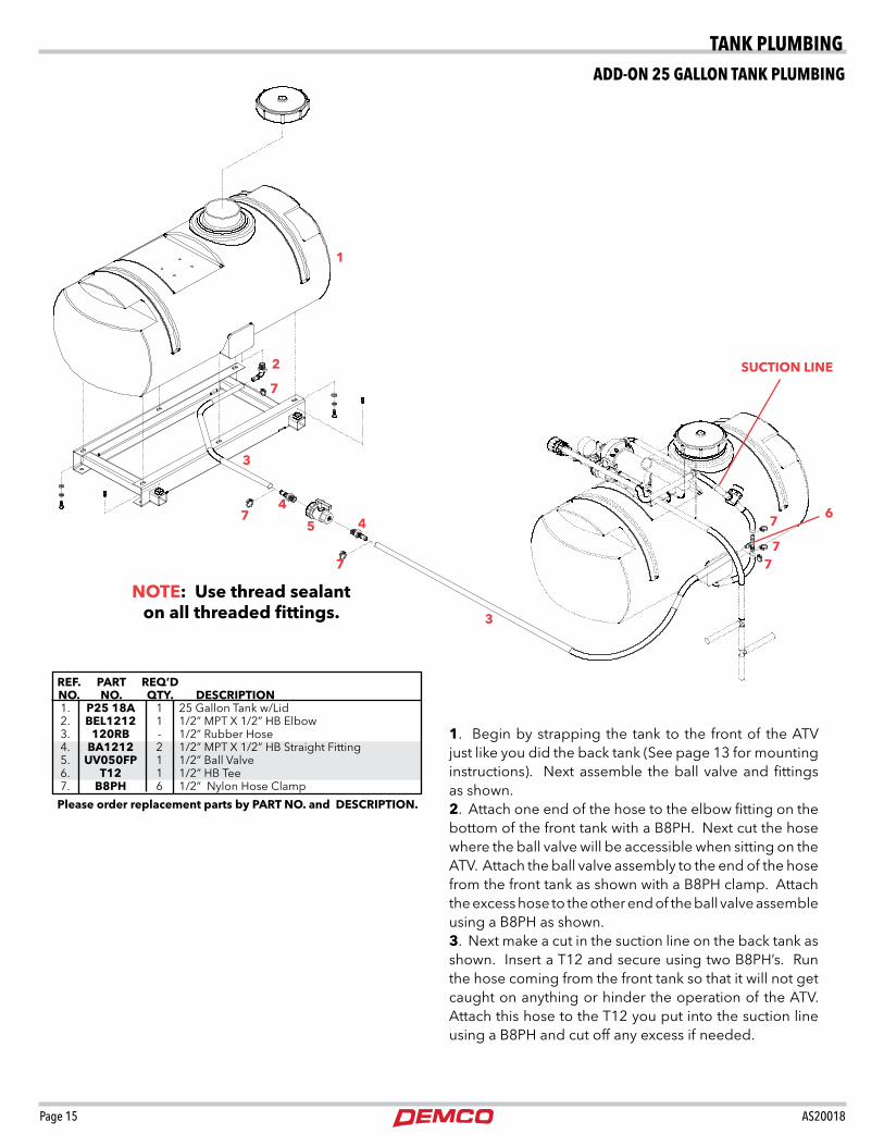
1. Begin by strapping the tank to the front of the ATV just like you did the back tank (See page 13 for mounting instructions). Next assemble the ball valve and fittings as shown. 2. Attach one end of the hose to the elbow fitting on the bottom of the front tank with a B8PH. Next cut the hose where the ball valve will be accessible when sitting on the ATV. Attach the ball valve assembly to the end of the hose from the front tank as shown with a B8PH clamp. Attach the excess hose to the other end of the ball valve assemble using a B8PH as shown. 3. Next make a cut in the suction line on the back tank as shown.InsertaT12andsecureusingtwoB8PH’s.Runthe hose coming from the front tank so that it will not get caught on anything or hinder the operation of the ATV. Attach this hose to the T12 you put into the suction line using a B8PH and cut off any excess if needed.
Please order replacement parts by PART NO. and DESCRIPTION.
1. P25 18A 1 25 Gallon Tank w/Lid 2. BEL1212 1 1/2” MPT X 1/2” HB Elbow 3. 120RB - 1/2” Rubber Hose 4. BA1212 2 1/2” MPT X 1/2” HB Straight Fitting 5. uv050FP 1 1/2” Ball Valve 6. T12 1 1/2” HB Tee 7. B8PH 6 1/2” Nylon Hose Clamp
2
5
44
6
3
7
1
NOTE: use thread sealant on all threaded fittings.
SuCTION LINE
3
7
7
7
7
7
tANk pLUMBINGADD-ON 25 GALLON tANk pLUMBING

Page 16 AS20018
4
1
1
4
6
35
5
3
6
3
4
42
1. 10950-30 2 Boom Mounts *2. 02680-10 1 Truss-T Center Section *3. 02678-95 4 Boom Mounting Plate *4. 00909 8 5/16”-18 UNC 1-1/4” Square U-Bolt *5. 00004 16 5/16” Flatwasher *6. 02802 16 5/16” Nylon Insert Locknut
REF. PART NO. NO. QTy. DESCRIPTION
* Parts included with the boom
1. Attach the mounting plates (#3) to the center section (#2) using four 5/16” X 1-1/4” square u-bolts (#4), eight 5/16” flatwashers (#5), and eight 5/16” nylon insert locknuts (#6). Leave these loose at this time to allow for adjustment.
2. Now attach this assembly to the boom mounts (#1) on the ATV using four 5/16” X 1-1/4” square u-bolts (#4), eight 5/16” flatwashers (#5), and eight 5/16” nylon insert locknuts (#6). Adjust the center section to the desired spray height and tighten all nuts at this time.
Please order replacement parts by PART NO. and DESCRIPTION.
*NOTE: Truss-T booms come standard with 1/2” hose and T’s.
BOOM MOUNtING INStRUCtIONS
MOUNtING INStRUCtIONS

Page 17 AS20018
DOuBLEOvERLAP
10 .15 11.2 7.5 5.6 4.5 3.7 3.2 2.8 20 .21 15.8 10.5 7.9 6.3 5.3 4.6 3.9 30 .26 19.4 12.9 9.7 7.7 6.4 5.6 4.8 40 .30 22.2 14.8 11.1 8.9 7.4 6.5 5.6
3.0 23 45 68 4.0 17 34 51 5.0 14 27 41 6.0 11 23 34 7.0 9.7 19 29 8.0 8.5 17 26 10 6.8 14 20
.05 300 .20 75 .06 250 .225 67 .07 214 .25 60 .08 188 .30 50 .09 167 .35 43 .10 150 .40 38 .11 136 .50 30 .12 125 .60 25 .13 115 .70 21 .14 107 .80 19 .15 100 .90 17 .17 88 1.0 15
speed in MPH (miles per hr.) 100 feet 200 feet 300 feet
vEHICLE SPEEDSMark off a distance of 100, 200 or 300 feet. Run the lawn mower or all terrain vehicle over this distance, carefully marking the throttle setting or speedometer reading. To make measurement of test run, begin from a standing start far enough ahead of the first marker so that your rig is at full speed before traveling the 100, 200 or 300 foot distances.
time required in SECONDS to travel:
seconds seconds GPM to collect 1 qt. GPM to collect 1 qt.
RATES OF FLOW...for calibrating spray tips.
use the following formula to determine your ratio per acre.GPA - Gallons Per AcreGPM - Gallons Per MinuteMPH - Miles Per Hour
5940 x GPM (Per Nozzle) MPH x W** W - Nozzle spacing in inches.
GPA =
Important: Replace all worn tips and those with streaky or uneven patterns.
Liquid Capacity Pressure 1 Nozzle in in 2 3 4 5 6 7 8 Tip No. PSI GPM MPH MPH MPH MPH MPH MPH MPH
GALLONS PER ACRE40” TIP SPACING
AN1.5
Spray Tip Chart for 80” and 144” Booms
Liquid Capacity Pressure 1 Nozzle in in 2 3 4 5 6 7 8 Tip No. PSI GPM MPH MPH MPH MPH MPH MPH MPH
GALLONS PER ACRE30” TIP SPACING
LP015 110
Spray Tip Chart for 90” Booms
Liquid Capacity Pressure 1 Nozzle in in 2 3 4 5 6 7 8 Tip No. PSI GPM MPH MPH MPH MPH MPH MPH MPH
GALLONS PER ACRE40” TIP SPACING
LP015 110
Spray Tip Chart for Single Tip (40”) Booms
Acre =43,560 square feet
*approximately 13-1/2” for 30” coverage.*approximately 15” for 40” coverage.This tip (LP015 110 ) is specially designed to operate at low pressure, and wide angle allowing the boom to be run close to the ground for less spray drift.
TIP
SPACING
30%OvERLAP
*SPRAyHEIGHT
There is not a standard spray height for FloodJet tips. Raise or lower the spray boom. . . or rotate nozzle tips to double overlap spray patterns and provide optimum coverage along spray boom.
When switching from one chemical to another chemical in the sprayer where contamination must be prevented, wash out with ammonia and water through the tank, pump and all hose. Then flush with water two or three times. Herbicides such as 2-4-D are hard to remove. After using them, follow the special cleaning procedures noted on the pesticide label.
TIP
SPACING
15 .15 14.8 9.9 7.4 5.9 5.0 4.2 3.7 20 .17 17.2 11.5 8.6 6.9 5.7 4.9 4.3 30 .21 21.0 14.0 10.5 8.4 7.0 6.0 5.3 40 .24 24.2 16.2 12.1 9.7 8.1 6.9 6.0
15 .15 11.2 7.5 5.6 4.5 3.7 3.2 2.8 20 .17 13.0 8.7 6.5 5.2 4.3 3.7 3.2 30 .21 15.8 10.5 7.9 6.3 5.3 4.5 3.7 40 .24 18.2 12.1 9.1 7.3 6.1 5.2 4.6
CALIBRAtION INStRUCtIONS
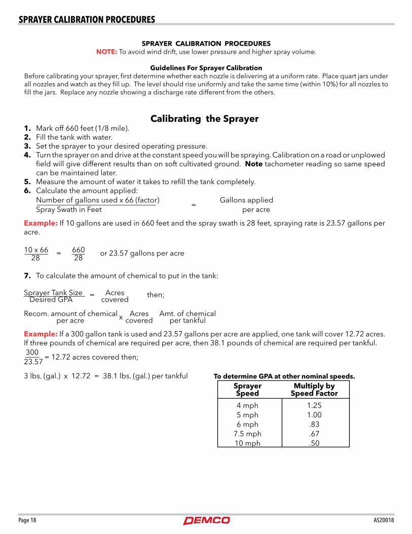
Page 18 AS20018
Calibrating the Sprayer1. Mark off 660 feet (1/8 mile).2. Fill the tank with water.3. Set the sprayer to your desired operating pressure.4. Turn the sprayer on and drive at the constant speed you will be spraying. Calibration on a road or unplowed
field will give different results than on soft cultivated ground. Note tachometer reading so same speed can be maintained later.
5. Measure the amount of water it takes to refill the tank completely.6. Calculate the amount applied: Number of gallons used x 66 (factor) Gallons applied = Spray Swath in Feet per acre
Example: If 10 gallons are used in 660 feet and the spray swath is 28 feet, spraying rate is 23.57 gallons per acre.
10 x 66 660 = or 23.57 gallons per acre 28 28
7. To calculate the amount of chemical to put in the tank:
Sprayer Tank Size Acres = then; Desired GPA covered
Recom. amount of chemical Acres Amt. of chemical x per acre covered per tankful Example: If a 300 gallon tank is used and 23.57 gallons per acre are applied, one tank will cover 12.72 acres. If three pounds of chemical are required per acre, then 38.1 pounds of chemical are required per tankful. 300 =12.72acrescoveredthen;23.57
3 lbs. (gal.) x 12.72 = 38.1 lbs. (gal.) per tankful
SPRAyER CALIBRATION PROCEDuRESNOTE: To avoid wind drift, use lower pressure and higher spray volume.
Guidelines For Sprayer CalibrationBefore calibrating your sprayer, first determine whether each nozzle is delivering at a uniform rate. Place quart jars under all nozzles and watch as they fill up. The level should rise uniformly and take the same time (within 10%) for all nozzles to fill the jars. Replace any nozzle showing a discharge rate different from the others.
Sprayer Multiply by Speed Speed Factor
4 mph 1.25 5 mph 1.00 6 mph .83 7.5 mph .67 10 mph .50
To determine GPA at other nominal speeds.
SpRAyeR CALIBRAtION pROCeDUReS

Page 19 AS20018
FLAT SPRAy NOzzLEFOR BROADCAST SPRAyING
FLOODjET TIPSFOR BROADCAST SPRAyING
Tabulations for all the following charts are based on spraying water. For different weight fertilizer solutions, obtain the appropriate conversion factor from the table below.
17” to 19”
TIPS SPACED 20” APART20”
Nozzle Spacing20”
Nozzle Spacing
Floodjet tips are positioned as shown in the diagram by the chart below. When positioning the tip as shown in Figure A the chance of wind drift is reduced. The chart below shows capacities in gallons per acre at various speeds and liquid pressures. Capacities are based on water at 70 degrees F. with nozzles spaced at 40 inches.
Specific Conversion Weight of Solution Gravity Factors 7.0 lbs. per gallon .84 1.09 8.0 lbs. per gallon .96 1.02 8.34 lbs. per gallon-WATER 1.00 1.00 9.0 lbs. per gallon 1.08 .96 10.0 lbs. per gallon 1.20 .91 11.0 lbs. per gallon 1.32 .87 12.0 lbs. per gallon 1.44 .83 14.0 lbs. per gallon 1.68 .77 16.0 lbs. per gallon 1.92 .72 18.0 lbs. per gallon 2.16 .68 20.0 lbs. per gallon 2.40 .65
Imperial Gallon = 1.20 U.S.A. Gallons
Liquid Capacity Gallons Per Acre Nozzle Orifice Pressure In 4 5 6 8 10 No. Dia. In PSI. GPM. MPH MPH MPH MPH MPH
TKvS1 .033” 10 .10 3.7 3.0 2.5 1.9 1.5 20 .14 5.3 4.3 3.5 2.6 2.1 30 .17 6.4 5.1 4.2 3.2 2.6 40 .20 7.4 6.0 4.9 3.7 3.0 TKvS1.5 .041” 10 .15 5.6 4.5 3.7 2.7 2.0 20 .21 7.8 6.3 5.2 3.9 2.9 30 .26 9.7 7.7 6.5 4.8 3.5 40 .30 11.1 8.9 7.4 5.6 4.1
TKvS2 .046” 10 .20 7.4 6.0 4.9 3.7 3.0 20 .28 10.5 8.4 6.9 5.2 4.2 30 .35 12.9 10.3 8.7 6.5 5.2 40 .40 14.8 11.8 9.9 7.5 5.9
TKvS2.5 .052” 10 .25 9.3 7.4 6.1 4.6 3.7 20 .35 12.9 10.3 8.7 6.5 5.2 30 .43 15.9 12.8 10.6 8.0 6.4 40 .50 18.6 14.9 12.4 9.3 7.4
TKvS3 .057” 10 .30 11.1 8.9 7.5 5.6 4.5 20 .42 15.7 12.6 10.4 7.8 6.3 30 .52 19.3 15.4 12.8 9.7 7.7 40 .60 22.0 17.8 14.8 11.2 8.9
TKvS4 .065” 10 .40 14.9 11.9 9.9 7.5 5.9 20 .57 21.0 16.8 13.9 10.5 8.4 30 .69 26.0 21.0 17.1 12.8 10.3 40 .80 30.0 24.0 19.8 14.8 11.9
TKvS5 .073” 10 .50 18.6 14.9 12.4 9.3 7.4 20 .71 27.0 21.0 17.6 13.1 10.7 30 .87 33.0 26.0 21.7 16.1 13.1 40 1.00 38.0 30.0 25.2 18.6 15.1
TKvS7.5 .091 10 .75 28.0 22.0 18.7 14.0 11.1 20 1.10 39.0 32.0 26.4 19.8 15.8 30 1.30 49.0 39.0 31.9 24.1 19.3 40 1.50 56.0 45.0 37.4 27.5 22.0
TKvS10 .104” 10 1.00 38.0 30.0 25.2 18.5 15.1 20 1.40 53.0 41.7 35.2 26.4 21.0 30 1.70 64.0 51.0 41.7 31.9 26.0 40 2.00 75.0 60.0 49.4 37.4 30.0
TKSS15 .129” 10 1.50 56.0 45.0 37.4 27.5 22.0 20 2.10 79.0 63.0 51.6 39.6 31.0 30 2.60 97.0 77.0 64.8 48.3 39.0 40 3.00 111.0 89.0 74.7 56.0 45.0
TKSS20 .148” 10 2.00 75.0 60.0 49.4 37.4 30.0 20 2.80 104.0 83.0 69.2 52.7 42.0 30 3.50 130.0 104.0 86.8 64.8 52.0 40 4.00 149.0 119.0 100.0 74.7 59.0
TKSS30 .180” 10 3.00 111.0 89.0 74.7 56.0 45.0 20 4.2 156.0 124.0 104.4 78.2 62.0 30 5.10 189.0 151.0 1264 95.6 76.0 40 6.000 222.0 178.0 149.4 112.0 89.0
Other Spacing 20 24 28 30 32 34 36 38 40 42 44 Conversion Factor 2 1.67 1.43 1.33 1.25 1.18 1.11 1.05 1.00 .95 .91
Figure A
The rate chart is based on 40 inch row spacings. For other spacings of nozzles on the boom, multiply the tabulated GPA coverage by the conversion factors shown below.
Flat uniform Sprayer Pattern
6” to 7”
TIPS SPACED 40” APART40”
Nozzle Spacing
Gallons Per Acre Liquid Nozzle Based on 20” Nozzle Spacing Nozzle Pressure Capacity 4 5 7.5 10 No. In PSI. In GPM MPH MPH MPH MPH 8001 20 .07 5.3 4.3 2.8 2.2 or 25 .08 5.9 4.7 3.1 2.4 XR8001vS 30 .09 6.4 5.1 3.4 2.6 40 .10 7.4 6.0 4.0 3.0 80015 20 .11 7.8 6.3 4.3 3.2 or 25 .12 8.8 7.1 4.7 3.6 XR80015vS 30 .13 9.7 7.7 5.2 3.9 40 .15 11.1 8.9 6.0 4.5 8002 20 .14 10.5 8.4 5.6 4.2 or 25 .16 11.8 9.4 6.3 4.7 XR8002vS 30 .17 12.9 10.3 6.9 5.2 40 .20 14.8 11.8 7.9 5.9 8003 20 .21 15.7 12.6 8.4 6.3 or 25 .24 17.6 14.1 9.4 7.1 XR8003vS 30 .26 19.0 15.4 10.3 7.7 40 .30 22.0 17.8 11.8 8.9 8004 20 .28 21.0 16.8 11.2 8.4 or 25 .32 24.0 18.7 12.5 9.4 XR8004vS 30 .35 26.0 21.0 13.7 10.3 40 .40 30.0 24.0 15.8 11.9 8005 20 .35 26.0 21.0 14.0 10.5 or 25 .40 29.0 23.0 15.7 11.7 XR8005vS 30 .43 32.0 26.0 17.2 12.9 40 .50 37.0 30.0 19.8 14.9 8006 20 .42 31.0 25.0 16.9 12.6 or 25 .47 35.0 28.0 18.7 14.1 XR8006vS 30 .52 39.0 31.0 21.0 15.5 40 .60 45.0 36.0 24.0 17.8 8008 20 .56 42.0 34.0 22.0 17.0 or 25 .63 47.0 37.0 25.0 19.0 XR8008vS 30 .69 52.0 41.0 27.0 21.0 40 .80 59.0 48.0 32.0 24.0 8010 20 .70 53.0 42.0 28.0 21.0 or 25 .78 59.0 47.0 31.0 24.0 XR8010vS 30 .86 64.0 51.0 34.0 26.0 40 1.00 74.0 59.0 40.0 30.0
CALIBRAtION INStRUCtIONS

Page 20 AS20018
AB23120 Repair Kit (Includes Guide Pin, Rubber O-Ring, and Spring)
PART NO. DESCRIPTION
(23120PP) PRESSuRE RELIEF vALvE PARTS BREAKDOWN
(23120PP) ByPASS vALvE PARTS LIST
Please order replacement parts by PART NO. and DESCRIPTION.
INCLuDED IN REPAIR KIT
SPRAy WAND PARTS BREAKDOWN
REF. PART NO. NO. DESCRIPTION
1. 19684 1NyB Housing Assembly 2. 17013 1zP Screw 3. 19818 1zP Screw 4. 19819SS Washer 5. 19816 Spring Retainer 6. *22138 302SS Spring 7. 19815 Spring Guide 8. 19810 Trigger Guide 9. 19805DEL Lock Spring Ring 10. 19806FRP Trigger Lock 11. 17703FRP Trigger 12. 19820 420SS Roll Pin 13. 17720 420SS Roll Pin 14. 7622INP #6 Burr
SPRAy WAND PARTS BREAKDOWN
Please order replacement parts by PART NO. and DESCRIPTION.
REF. PART NO. NO. DESCRIPTION
2
3 4 5 6 7 8
9 1011
12
13
14
15
16
17
18
19
20 21 22
23 24 24 25 26
15. 7489 302SS Trigger Stop Spring
17. 19811 Packing Screw 16. 7484INP Stem Nut
1
18. *19812AL Gasket 19. *14255 1Bu Packing Cup 20. 22427 18SS Stem 18” 21. 7679 1 Stem Guide Nut 22. *7678 Stem End 23. 22136 Inlet Body 24. 7715 18 18” Wand Extension 25. *7490BRTF Valve Seat sub-assembly 26. 5500 18PP Adjustable Tip (ordered separately) Not included with wand above. AB30L Parts Kit (includes all items with *)
pARtS BReAkDOWN

Page 21 AS20018
5 GPM ELECTRIC PuMP (12981) PARTS BREAKDOWN
Document PF5800/5900 Install 04.15.08
5
6
1
2
3
4
5
6
1
2
3
4
5
1 Lower Housing ............................................................................................................................................ 1 5830/5836 - 5930/5936 – Demand or Bypass ........................................................ LHA5510-1E77 5840/5940 – Demand or Bypass............................................................................. LHA5512-1E77 5850/5950 – Demand or Bypass............................................................................. LHA5513-1E77
2 Valve Assembly ........................................................................................................................................... 1 5800/5900 Series Pumps ......................................................................................VHA-5513-1E77
3 Upper Housing ............................................................................................................................................. 1 5800 w/Pressure Switch ....................................................................................... UHA-5513-1E77 5800 w/Bypass..................................................................................................... UHA-5513-2E77 5900 w/Pressure Switch ....................................................................................... UHA-5503-1E77 5900 w/Bypass..................................................................................................... UHA-5503-2E77
4 Mounting Bolts ........................................................................................................................... MB-5500-1 4
5 Complete Pump Head w/Threaded Ports .................................................................................................... 1 5830/5836 w/Pressure Switch .......................................................................................5510-1X77 5830/5836 w/Bypass ....................................................................................................5510-2X77 5840 w/Pressure Switch ................................................................................................5512-1X77 5840 w/Bypass..............................................................................................................5512-2X77 5850 w/Pressure Switch ................................................................................................5513-1X77 5850 w/Bypass..............................................................................................................5513-2X77 Complete Pump Head w/Quick Attach Ports .............................................................................................. 1 5930/5936 w/Pressure Switch .......................................................................................5500-1X77 5930/5936 w/Bypass ....................................................................................................5500-2X77 5940 w/Pressure Switch ................................................................................................5502-1X77 5940 w/Bypass..............................................................................................................5502-2X77 5950 w/Pressure Switch ................................................................................................5503-1X77 5950 w/Bypass..............................................................................................................5503-2X77
6 12 VDC Motor ............................................................................................................................................. 1 5800/5900 Series w/No Switch, No Connector ................................................................ M12-58A 5800/5900 Series w/Connector, No Switch ...................................................................... M12-58B 5800/5900 Series w/Switch and Connector ...................................................................... M12-58C 5800/5900 w/Bypass ................................................................................................M70-563-MO
PowerFlow Models 5800/5900
REF. PART NO. NO. DESCRIPTION
Please order replacement parts by PART NO. and DESCRIPTION.
PARTS LIST
1. 13029 Lower Housing Assembly 2. 13028 Valve Assembly 3. 13030 Upper Housing Assembly
pARtS BReAkDOWN

Page 22 AS20018
SPRAyER CHECKLIST:
Downtime caused by field breakdowns is costly and time consuming. Many breakdowns can be eliminated by periodic equipment maintenance. By spending time reviewing this checklist before seasonal spraying application time and following proper after-season care, you can save time and money later.
NOTE: DEMCO does not and will not make any recom-mendations concerning application of various chemicals or solutions. These recommendations relate to either amount or procedure of materials applied. If you have any questions regarding ap-plication of certain chemicals or solutions, contact your chemical supplier and follow chemical manu-facturer recommendations.
Check Before Going To The Field :
1. NOzzLES Check tip for excessive wear by checking for grooves
in or near tip opening. Check nozzle spacing by start-ing at center and working outwards. Check boom for proper height.
2. HOSES Check all hoses for worn or soft spots. Be sure all hose
clamps are tightened and hoses are not kinked or pinched. Check for leakage in any lines.
3. TANK Remove and clean agitator orifices. Check orifices
for excessive wear by checking for grooves in or near orifice opening. Inspect fitting and grommets to insure they are in good condition.
4. CONTROLS Check for leakage, plugging, or wear on all valves, fit-
tings, etc. Clean off any build up of foreign material.
5. PuMP Check to be sure pump turns freely.
6. FRAME Be sure all bolts are tightened.
7. REPLACEMENT PARTS Replace all worn or damaged parts.
After Season Care:
NOTE: It is important to wear proper safety equipment when cleaning the sprayer. See your chemical or fertilizer package for this information.
1. After spraying chemicals, run water mixed with cleaners through tank, pump and all hose hookups. If wettable powder dries out in the system, it is very difficult to put back into suspension and can cause malfunction, damage or injury.
2. When cleaned, tank should have all openings closed or covered to keep dirt from entering.
3. Pump should be flushed with soluble oil and pump ports plugged to keep out moisture and air.
4. Disassemble tips and rinse with water or cleaning solution. (Appropriate for chemical sprayed).
5. Clean tip opening with a wooden toothpick. Never use wire or hard object that could distort opening.
6. Dispose of all unused chemicals or solutions in a proper and ecologically sound manner.
7. Water rinse and dry tips before storing.
8. To prevent damage due to freezing temperatures, be sure to drain all strainer bowls. Furthermore, run RV Antifreeze through the entire plumbing system to protect valves and other components.
• Keephands,feet,andlooseclothingawayfromrotatingparts.
• Wearprotectiveclothingrecommendedbyyourchemicalandfertilizermanufac turer when working with chemicals.
WARNING: TO PREvENT SERIOuS INjuRy OR DEATH:
SpRAyeR CheCkLISt

Page 23 AS20018
