atv32 modbus manual -...
TRANSCRIPT

Altivar 32Variable speed drives forsynchronous and asynchronous motors
Modbus Communication Manual
03/2010
S1A
2869
8
www.schneider-electric.com
The information provided in this documentation contains general descriptions and/or technical characteristics of the performance of the products contained herein. This documentation is not intended as a substitute for and is not to be used for determining suitability or reliability of these products for specific user applications. It is the duty of any such user or integrator to perform the appropriate and complete risk analysis, evaluation and testing of the products with respect to the relevant specific application or use thereof. Neither Schneider Electric nor any of its affiliates or subsidiaries shall be responsible or liable for misuse of the information contained herein. If you have any suggestions for improvements or amendments or have found errors in this publication, please notify us.
No part of this document may be reproduced in any form or by any means, electronic or mechanical, including photocopying, without express written permission of Schneider Electric.
All pertinent state, regional, and local safety regulations must be observed when installing and using this product. For reasons of safety and to help ensure compliance with documented system data, only the manufacturer should perform repairs to components.
When devices are used for applications with technical safety requirements, the relevant instructions must be followed.
Failure to use Schneider Electric software or approved software with our hardware products may result in injury, harm, or improper operating results.
Failure to observe this information can result in injury or equipment damage.
© 2010 Schneider Electric. All rights reserved.
2 S1A28698 03/2010

Table of Contents
Table of Contents
Safety Information . . . . . . . . . . . . . . . . . . . . . . . . . . . . . . . . . . . . . . . . . . . . . . . . . . . . 5About the Book. . . . . . . . . . . . . . . . . . . . . . . . . . . . . . . . . . . . . . . . . . . . . . . . . . . . . . . 6
Chapter 1 Hardware Setup . . . . . . . . . . . . . . . . . . . . . . . . . . . . . . . . . . . . . . . . . . . . . . . . . . . . . . . 8Connection to ATV32 . . . . . . . . . . . . . . . . . . . . . . . . . . . . . . . . . . . . . . . . . . . . . . . . . . . 9Protection Against Interference . . . . . . . . . . . . . . . . . . . . . . . . . . . . . . . . . . . . . . . . . . . 9RS485 Bus Schematic . . . . . . . . . . . . . . . . . . . . . . . . . . . . . . . . . . . . . . . . . . . . . . . . . 10
Chapter 2 Configuration . . . . . . . . . . . . . . . . . . . . . . . . . . . . . . . . . . . . . . . . . . . . . . . . . . . . . . . . 11Notation . . . . . . . . . . . . . . . . . . . . . . . . . . . . . . . . . . . . . . . . . . . . . . . . . . . . . . . . . . . . 12Configuring the Communication Parameters . . . . . . . . . . . . . . . . . . . . . . . . . . . . . . . . 13Configuring the Control Channels . . . . . . . . . . . . . . . . . . . . . . . . . . . . . . . . . . . . . . . . 14I/O Scanner . . . . . . . . . . . . . . . . . . . . . . . . . . . . . . . . . . . . . . . . . . . . . . . . . . . . . . . . . 16Configuring Monitor Parameters. . . . . . . . . . . . . . . . . . . . . . . . . . . . . . . . . . . . . . . . . . 18Configuring Communication Interruption Management . . . . . . . . . . . . . . . . . . . . . . . . 19
Chapter 3 Diagnostics . . . . . . . . . . . . . . . . . . . . . . . . . . . . . . . . . . . . . . . . . . . . . . . . . . . . . . . . . . 20Communication Diagnostics . . . . . . . . . . . . . . . . . . . . . . . . . . . . . . . . . . . . . . . . . . . . . 21Modbus Counters . . . . . . . . . . . . . . . . . . . . . . . . . . . . . . . . . . . . . . . . . . . . . . . . . . . . . 21Modbus Communication Stat . . . . . . . . . . . . . . . . . . . . . . . . . . . . . . . . . . . . . . . . . . . . 21
Chapter 4 Profiles . . . . . . . . . . . . . . . . . . . . . . . . . . . . . . . . . . . . . . . . . . . . . . . . . . . . . . . . . . . . . 22Definition of a Profile . . . . . . . . . . . . . . . . . . . . . . . . . . . . . . . . . . . . . . . . . . . . . . . . . . 23Functional Profiles Supported by the Altivar 32 . . . . . . . . . . . . . . . . . . . . . . . . . . . . . . 24
Chapter 5 CiA®402 - IEC61800-7 Functional Profile . . . . . . . . . . . . . . . . . . . . . . . . . . . . . . . . . . 25Functional Description . . . . . . . . . . . . . . . . . . . . . . . . . . . . . . . . . . . . . . . . . . . . . . . . . 26CiA402 State Chart . . . . . . . . . . . . . . . . . . . . . . . . . . . . . . . . . . . . . . . . . . . . . . . . . . . 27Description of States . . . . . . . . . . . . . . . . . . . . . . . . . . . . . . . . . . . . . . . . . . . . . . . . . . 28Summary . . . . . . . . . . . . . . . . . . . . . . . . . . . . . . . . . . . . . . . . . . . . . . . . . . . . . . . . . . . 29Control Word (CMd) . . . . . . . . . . . . . . . . . . . . . . . . . . . . . . . . . . . . . . . . . . . . . . . . . . . 30Stop Commands. . . . . . . . . . . . . . . . . . . . . . . . . . . . . . . . . . . . . . . . . . . . . . . . . . . . . . 31Assigning Control Word Bits . . . . . . . . . . . . . . . . . . . . . . . . . . . . . . . . . . . . . . . . . . . . . 31Status Word (EtA). . . . . . . . . . . . . . . . . . . . . . . . . . . . . . . . . . . . . . . . . . . . . . . . . . . . . 32Starting Sequence . . . . . . . . . . . . . . . . . . . . . . . . . . . . . . . . . . . . . . . . . . . . . . . . . . . . 33Sequence for a Drive Powered by the Power Section Line Supply . . . . . . . . . . . . . . . 34Sequence for a Drive With Separate Control Section . . . . . . . . . . . . . . . . . . . . . . . . . 36Sequence for a Drive with Line Contactor Control . . . . . . . . . . . . . . . . . . . . . . . . . . . . 39
Chapter 6 Software Setup with Unity (M340) . . . . . . . . . . . . . . . . . . . . . . . . . . . . . . . . . . . . . . . . 41Introduction. . . . . . . . . . . . . . . . . . . . . . . . . . . . . . . . . . . . . . . . . . . . . . . . . . . . . . . . . . 42Drive Configuration. . . . . . . . . . . . . . . . . . . . . . . . . . . . . . . . . . . . . . . . . . . . . . . . . . . . 43Modbus Master Configuration . . . . . . . . . . . . . . . . . . . . . . . . . . . . . . . . . . . . . . . . . . . 44
Chapter 7 Software Setup with SoMachine (M238) . . . . . . . . . . . . . . . . . . . . . . . . . . . . . . . . . . . 49Introduction. . . . . . . . . . . . . . . . . . . . . . . . . . . . . . . . . . . . . . . . . . . . . . . . . . . . . . . . . . 50Drive Configuration. . . . . . . . . . . . . . . . . . . . . . . . . . . . . . . . . . . . . . . . . . . . . . . . . . . . 51Modbus Master Configuration . . . . . . . . . . . . . . . . . . . . . . . . . . . . . . . . . . . . . . . . . . . 52
Chapter 8 Modbus Functions . . . . . . . . . . . . . . . . . . . . . . . . . . . . . . . . . . . . . . . . . . . . . . . . . . . . 56Modbus Protocol. . . . . . . . . . . . . . . . . . . . . . . . . . . . . . . . . . . . . . . . . . . . . . . . . . . . . . 57
S1A28699 03/2010 3

Table of Contents
Supported Modbus Functions. . . . . . . . . . . . . . . . . . . . . . . . . . . . . . . . . . . . . . . . . . . . 58
4 S1A28699 03/2010

§
Safety Information
Safety Information
Important Information
NOTICERead these instructions carefully, and look at the equipment to become familiar with the device before trying to install, operate, or maintain it. The following special messages may appear throughout this documentation or on the equipment to warn of potential hazards or to call attention to information that clarifies or simplifies a procedure.
PLEASE NOTEThe word “drive” as used in this manual refers to the controller portion of the adjustable speed drive as defined by NEC.
Electrical equipment should be installed, operated, serviced, and maintained only by qualified personnel. No responsibility is assumed by Schneider Electric for any consequences arising out of the use of this material.
The addition of this symbol to a Danger or Warning safety label indicates that an electrical hazard exists, which will result in personal injury if the instructions are not followed.
This is the safety alert symbol. It is used to alert you to potential personal injury hazards. Obey all safety message that follow this symbol to avoid possible injury or death.
DANGERDANGER indicates an imminently hazardous situation, which, if not avoided, will result in death or serious injury.
WARNINGWARNING indicates a potentially hazardous situation, which, if not avoided, can result in death, serious injury or equipment damage.
CAUTIONCAUTION indicates a potentially hazardous situation, which, if not avoided, can result in injury or equipment damage.
CAUTIONCAUTION, used without the safety alert symbol, indicates a potentially hazardous situation which, if not avoided, can result in equipment damage.
S1A28698 03/2010 5

About the Book
About the Book
At a Glance
Document ScopeThe purpose of this document is to:• show you how to install the Modbus fieldbus on your Altivar 32,• show you how to configure the Altivar 32 to use Modbus for monitoring and control,• provide examples of setup using SoMachine and Unity.
NOTE: Read and understand this document and all related documents (see below) before installing, operating, or maintaining your ATV32.
Validity NoteThis documentation is valid for the Altivar 32 Modbus fieldbus.
Related Documents
You can download the latest versions of these technical publications and other technical information from our website at www.schneider-electric.com.
Product Related Information
Title of Documentation Reference Number
ATV32 Quick Start S1A41715
ATV32 Installation manual S1A28686
ATV32 Programming manual S1A28692
ATV32 CANopen® manual S1A28699
ATV32 Communication Parameters S1A44568
ATV32 Atex manual S1A45605
ATV32 Safety manual S1A45606
ATV32 other option manuals: see www.schneider-electric.com
DANGERUNINTENDED EQUIPMENT OPERATION
• Read and understand this manual before installing or operating the Altivar 32 drive.• Any changes made to the parameter settings must be performed by qualified personnel.
Failure to follow these instructions will result in death or serious injury.
6 S1A28698 03/2010

About the Book
(1) For additional information, refer to NEMA ICS 1.1 (latest edition), “Safety Guidelines for the Application, Installation, and Maintenance of Solid State Control” and to NEMA ICS 7.1 (latest edition), “Safety Standards for Construction and Guide for Selection, Installation and Operation of Adjustable-Speed Drive Systems.”
DANGERHAZARD OF ELECTRIC SHOCK, EXPLOSION OR ARC FLASH
• Read and understand this manual before installing or operating the Altivar 32 drive. Installation, adjustment, repair, and maintenance must be performed by qualified personnel.
• The user is responsible for compliance with all international and national electrical code requirements with respect to grounding of all equipment.
• Many parts of this drive, including the printed circuit boards, operate at the line voltage. DO NOT TOUCH. Use only electrically insulated tools.
• DO NOT touch unshielded components or terminal strip screw connections with voltage present.• DO NOT short across terminals PA/+ and PC/– or across the DC bus capacitors.• Before servicing the drive:
- Disconnect all power, including external control power that may be present.- Place a “DO NOT TURN ON” label on all power disconnects.- Lock all power disconnects in the open position.- WAIT 15 MINUTES to allow the DC bus capacitors to discharge.- Measure the voltage of the DC bus between the PA/+ and PC/– terminals to ensure that the voltage is
less than 42 Vdc.- If the DC bus capacitors do not discharge completely, contact your local Schneider Electric
representative. Do not repair or operate the drive• Install and close all covers before applying power or starting and stopping the drive.
Failure to follow these instructions will result in death or serious injury.
WARNINGDAMAGE DRIVE EQUIPMENT Do not operate or install any drive or drive accessory that appears damaged.
Failure to follow these instructions can result in death, serious injury, or equipment damage.
WARNINGLOSS OF CONTROL
• The designer of any control scheme must - consider the potential failure modes of control paths and, - for certain critical control functions, provide a means to achieve a safe state during and after a path
failure. Examples of critical control functions are emergency stop and overtravel stop.• Separate or redundant control paths must be provided for critical control functions.• System control paths may include communication links. Consideration must be given to the implications
of unanticipated transmission delays or failures of the link.(1)
Failure to follow these instructions can result in death, serious injury, or equipment damage.
S1A28698 03/2010 7

8
Hardware Setup
1
Hardware SetupWhat's in this Chapter?This chapter contains the following topics:
Topic Page
Connection to ATV32 9
Protection Against Interference 9
RS485 Bus Schematic 10
S1A28698 03/2010

Hardware Setup
Connection to ATV32
Connection accessories should be ordered separately (please consult our catalogues).
Connect the RJ45 cable connector to the ATV32 connector.
The following table describes the pin out of the ATV32 RJ45 connector:
(1) Modbus signals(2) Supply for RS232 / RS485 converter or a remote terminal(3) The RJ45 base port is also used for the connection to a CANopen network when any CANopen option modules are
plugged
Protection Against Interference
• Use the Schneider Electric cable with 2 pairs of shielded twisted conductors (reference: TSXCSA100, TSXCSA200, TSXCSA500).
• Keep the Modbus cable separated from the power cables (30 cm (11.8 in.) minimum).• Make any crossovers of the Modbus cable and the power cables at right-angles, if necessary.
For more information, please refer to the TSX DG KBL E manual: “Electromagnetic compatibility of industrial networks and fieldbuses”.
Pin Signal
1 Reserved for CANopen (3)
2
3
4 D1 (1)
5 D0 (1)
6 -
7 VP, 10 Vdc (2)
8 Common
S1A28698 03/2010 9

Hardware Setup
RS485 Bus Schematic
The RS485 standard allows variants of different characteristics:• polarisation• line terminator• distribution of a reference potential• number of slaves• length of bus
The new Modbus specification published on the Modbus.org site in 2006 contains precise details of all these characteristics. They are also summarised in Standard schematic section. The new Schneider Electric devices conform to this specification.
Schematic Diagram
Characteristic Definition
Type of trunk cable Shielded cable with 1 twisted pair and at least a 3rd conductor
Maximum length of bus 1000m at 19200 bps with the Schneider Electric TSX CSA••• cable
Maximum number of stations (without repetear)
32 stations, i.e. 31 slaves
Maximum length of tap links - 20m for one tape link- 40m divided by the number of tape links on a multiple junction box
Bus polarisation - One 450 to 650Ω pull-down resistor at 5V (650Ω recommended)- One 450 to 650Ω pull-down resistor at the Common (650Ω recommended)
This polaristaion is recommended for the master
Line terminator One 120 H 0.25W resistor in series with 1nF 10V capacitor
Common polarity Yes (Common), connected to the protective ground at one or more point of the bus
MASTER
SLAVE 1 SLAVE n
10 S1A28698 03/2010
S1A28698 03/2010
Configuration
2
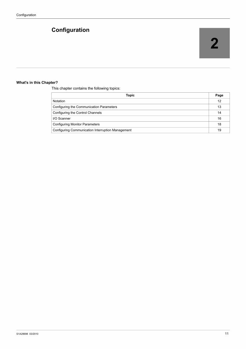
ConfigurationWhat's in this Chapter?This chapter contains the following topics:
Topic Page
Notation 12
Configuring the Communication Parameters 13
Configuring the Control Channels 14
I/O Scanner 16
Configuring Monitor Parameters 18
Configuring Communication Interruption Management 19
11

Configuration
Notation
Drive Terminal DisplaysThe graphic display terminal (to be ordered separately - reference VW3 A1 101) menus are shown in square brackets.
Example: [COMMUNICATION]
The integrated 7-segment display terminal menus are shown in round brackets.
Example: (COM-)
Parameter names are displayed on the graphic display terminal in square brackets.
Example: [Fallback speed]
Parameter codes are displayed on the integrated 7-segment display terminal in round brackets.
Example: (LFF)
Formats In this manual, hexadecimal values are written as follows: 16#
12 S1A28698 03/2010
Configuration
Configuring the Communication Parameters
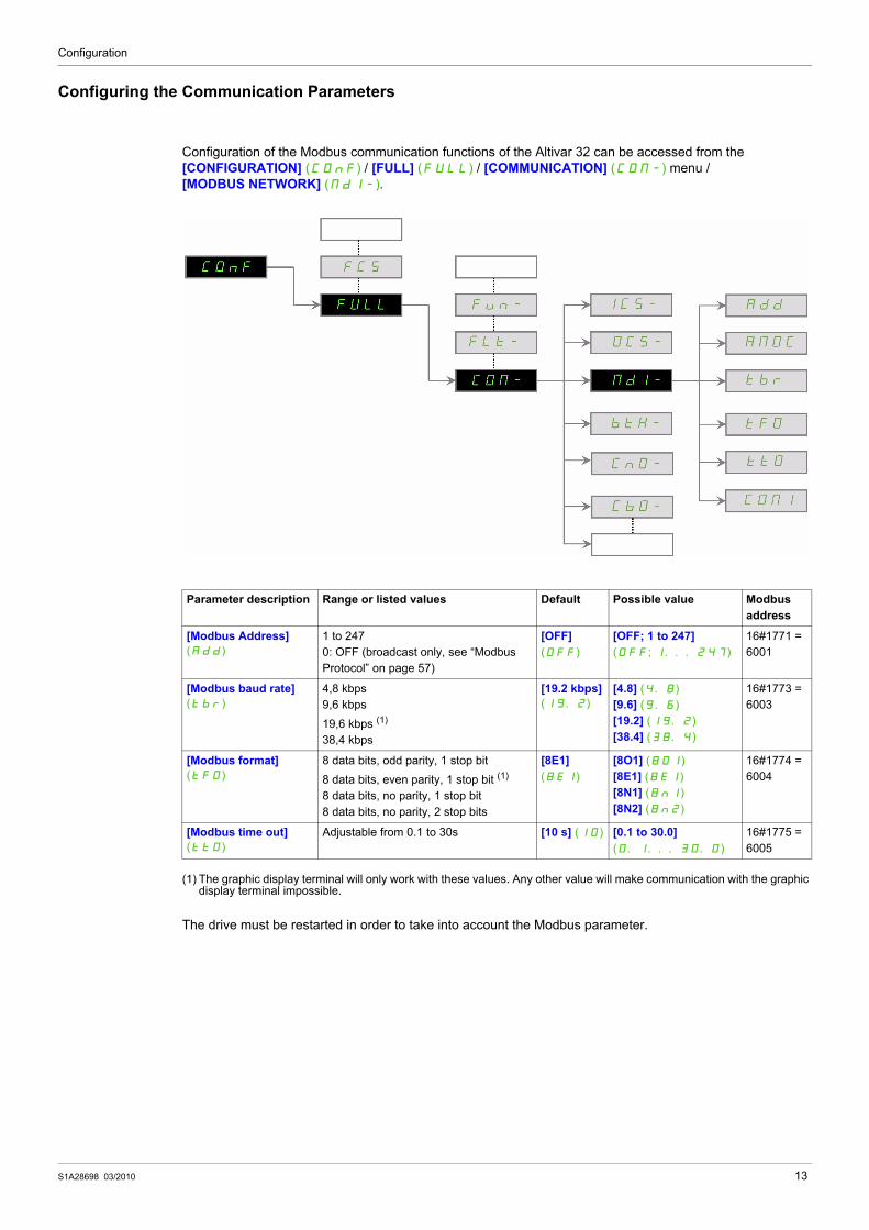
Configuration of the Modbus communication functions of the Altivar 32 can be accessed from the[CONFIGURATION] (COnF) / [FULL] (FULL) / [COMMUNICATION] (COM-) menu / [MODBUS NETWORK] (Md1-).
(1) The graphic display terminal will only work with these values. Any other value will make communication with the graphic display terminal impossible.
The drive must be restarted in order to take into account the Modbus parameter.
Parameter description Range or listed values Default Possible value Modbus address
[Modbus Address](Add)
1 to 2470: OFF (broadcast only, see “Modbus Protocol” on page 57)
[OFF] (OFF)
[OFF; 1 to 247] (OFF; 1...247)
16#1771 = 6001
[Modbus baud rate](tbr)
4,8 kbps9,6 kbps19,6 kbps (1)
38,4 kbps
[19.2 kbps](19.2)
[4.8] (4.8)[9.6] (9.6)[19.2] (19.2)[38.4] (38.4)
16#1773 = 6003
[Modbus format](tFD)
8 data bits, odd parity, 1 stop bit8 data bits, even parity, 1 stop bit (1)
8 data bits, no parity, 1 stop bit8 data bits, no parity, 2 stop bits
[8E1] (8E1)
[8O1] (8O1)[8E1] (8E1)[8N1] (8n1)[8N2] (8n2)
16#1774 = 6004
[Modbus time out](ttO)
Adjustable from 0.1 to 30s [10 s] (10) [0.1 to 30.0](0.1...30.0)
16#1775 = 6005
S1A28698 03/2010 13

Configuration
Configuring the Control Channels
This chapter explains through 3 examples how to configure the drive for operation from communication network:• I/O Mode - a simple command Word (based on Forward, reverse and reset binary commands).• Combined Mode (with native profile CiA402) - Both reference and command word come from the
communication network.• Separate (with native profile CiA402) - Reference and command come from separate sources: for example,
the command (in CiA402) comes from the communication network and the reference from the HMI.
Configuration of the Drive for Operation in I/O ProfileTo illustrate the I/O Profile, we will describe a simple example, which can be of course extended with additional features. The Command word is made of Run forward (bit 0 of CMD), run reverse (bit 1 of CMD), and a detected fault reset (bit 7 of CMD).
The settings will be the following:
The bits of the command word must now be configured.
In the [INPUTS / OUTPUTS CFG] Menu, configure:
In the [FAULT MANAGEMENT] menu, [FAULT RESET] submenu, configure:
[Ref.1 channel] (Fr1) [Modbus] (Mdb)
[Profile] (CHCF) [I/O profile] (IO)
[Cmd switching (CCS) Default
[Cmd channel 1] (Cd1) [Modbus] (Mdb)
[Forward] (Frd) [Cd00] (Cd00)
[Reverse assign.] (rrS) [Cd01] (Cd01)
[Fault reset] (rSF) [Cd07] (Cd07)
Reset
Run reverse
Run forward
[INPUTS / OUTPUTS CFG] / [Forward] is assigned to CMD bit 0[INPUTS / OUTPUTS CFG] / [Reverse assign.] is assigned to CMD bit 1
[FAULT MANAGEMENT] / [FAULT RESET] / [Fault reset] is assigned to CMD bit 7
14 S1A28698 03/2010
Configuration
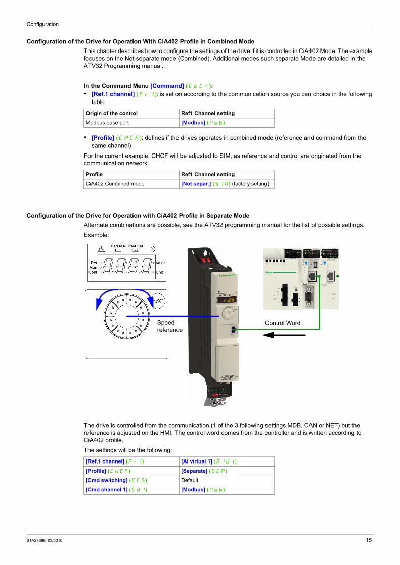
Configuration of the Drive for Operation With CiA402 Profile in Combined ModeThis chapter describes how to configure the settings of the drive if it is controlled in CiA402 Mode. The example focuses on the Not separate mode (Combined). Additional modes such separate Mode are detailed in the ATV32 Programming manual.
In the Command Menu [Command] (CtL-): • [Ref.1 channel] (Fr1): is set on according to the communication source you can choice in the following
table
• [Profile] (CHCF): defines if the drives operates in combined mode (reference and command from the same channel)
For the current example, CHCF will be adjusted to SIM, as reference and control are originated from the communication network.
Configuration of the Drive for Operation with CiA402 Profile in Separate ModeAlternate combinations are possible, see the ATV32 programming manual for the list of possible settings.
Example:
The drive is controlled from the communication (1 of the 3 following settings MDB, CAN or NET) but the reference is adjusted on the HMI. The control word comes from the controller and is written according to CiA402 profile.
The settings will be the following:
Origin of the control Ref1 Channel setting
Modbus base port [Modbus] (Mdb)
Profile Ref1 Channel setting
CiA402 Combined mode [Not separ.] (SIM) (factory setting)
[Ref.1 channel] (Fr1) [AI virtual 1] (AIU1)
[Profile] (CHCF) [Separate] (SEp)
[Cmd switching] (CCS) Default
[Cmd channel 1] (Cd1) [Modbus] (Mdb)
Control WordSpeed reference
S1A28698 03/2010 15

Configuration
I/O Scanner
IntroductionThe communication scanner is useful when used in combination by the Modbus client device with the function “Read/Write Multiple registers”: 23 (16#17), which provides in a single telegram a read multiple registers and a write multiple registers. The detail of the function 23 is described in the supported Modbus functions.
Local Configuration of the Communication ScannerThe communication scanner is accessible via the following menus: [COMMUNICATION] (COM-) and [COM. SCANNER INPUT] (ICS-), [COM. SCANNER OUTPUT] (OCS-) submenus.
The 8 output variables and the 8 input variables are assigned by means of parameters nCA1 to nCA8 and nMA1 to nMA8. An nCAx or nMAx parameter with a value of zero is not linked to a parameter in the drive. These parameters are described in the table.
nCAx or nMAx defines the addresses to:
Sub Menu Parameter description Defaultassignment
Modbusaddress
[COM. SCANNER INPUT](ICS-)
[Scan. IN1 address] (nMA1)Source drive address of the 1st input word
Status(ETA)
1270116#319D
[Scan. IN2 address] (nMA2)Source drive address of the 2nd input word
Output speed (RFRD)
1270216#319E
[Scan. IN3 address] (nMA3)Source drive address of the 3rd input word
0 1270316#319F
[Scan. IN4 address] (nMA4)Source drive address of the 4th input word
0 1270416#31A0
[Scan. IN5 address] (nMA5)Source drive address of the 5th input word
0 1270516#31A1
[Scan. IN6 address] (nMA6)Source drive address of the 6th input word
0 1270616#31A2
[Scan. IN7 address] (nMA7)Source drive address of the 7th input word
0 1270716#31A3
[Scan. IN8 address] (nMA8)Source drive address of the 8th input word
0 1270816#31A4
[COM. SCANNER OUTPUT](OCS-)
[Scan.Out1 address] (nCA1)Destination drive address of the 1st output word
Command (CMD)
1272116#31B1
[Scan.Out2 address] (nCA2)Destination drive address of the 2nd output word
Speed target (LFRD)
1272216#31B2
[Scan.Out3 address] (nCA3)Destination drive address of the 3rd output word
0 1272316#31B3
[Scan.Out4 address] (nCA4)Destination drive address of the 4th output word
0 1272416#31B4
[Scan.Out5 address] (nCA5)Destination drive address of the 5th output word
0 1272516#31B5
[Scan.Out6 address] (nCA6)Destination drive address of the 6th output word
0 1272616#31B6
[Scan.Out7 address] (nCA7)Destination drive address of the 7th output word
0 1272716#31B7
[Scan.Out8 address] (nCA8)Destination drive address of the 8th output word
0 1272816#31B8
16 S1A28698 03/2010
Configuration
Fast Task of the Communication ScannerOnly these parameters are available for fast tasks:
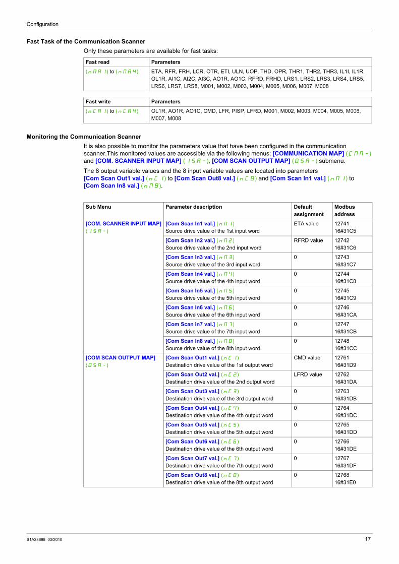
Monitoring the Communication ScannerIt is also possible to monitor the parameters value that have been configured in the communication scanner.This monitored values are accessible via the following menus: [COMMUNICATION MAP] (CMM-) and [COM. SCANNER INPUT MAP] (ISA-), [COM SCAN OUTPUT MAP] (OSA-) submenu.
The 8 output variable values and the 8 input variable values are located into parameters [Com Scan Out1 val.] (nC1) to [Com Scan Out8 val.] (nC8) and [Com Scan In1 val.] (nM1) to [Com Scan In8 val.] (nM8).
Fast read Parameters
(nMA1) to (nMA4) ETA, RFR, FRH, LCR, OTR, ETI, ULN, UOP, THD, OPR, THR1, THR2, THR3, IL1I, IL1R, OL1R, AI1C, AI2C, AI3C, AO1R, AO1C, RFRD, FRHD, LRS1, LRS2, LRS3, LRS4, LRS5, LRS6, LRS7, LRS8, M001, M002, M003, M004, M005, M006, M007, M008
Fast write Parameters
(nCA1) to (nCA4) OL1R, AO1R, AO1C, CMD, LFR, PISP, LFRD, M001, M002, M003, M004, M005, M006, M007, M008
Sub Menu Parameter description Defaultassignment
Modbusaddress
[COM. SCANNER INPUT MAP](ISA-)
[Com Scan In1 val.] (nM1)Source drive value of the 1st input word
ETA value 1274116#31C5
[Com Scan In2 val.] (nM2)Source drive value of the 2nd input word
RFRD value 1274216#31C6
[Com Scan In3 val.] (nM3)Source drive value of the 3rd input word
0 1274316#31C7
[Com Scan In4 val.] (nM4)Source drive value of the 4th input word
0 1274416#31C8
[Com Scan In5 val.] (nM5)Source drive value of the 5th input word
0 1274516#31C9
[Com Scan In6 val.] (nM6)Source drive value of the 6th input word
0 1274616#31CA
[Com Scan In7 val.] (nM7)Source drive value of the 7th input word
0 1274716#31CB
[Com Scan In8 val.] (nM8)Source drive value of the 8th input word
0 1274816#31CC
[COM SCAN OUTPUT MAP](OSA-)
[Com Scan Out1 val.] (nC1)Destination drive value of the 1st output word
CMD value 1276116#31D9
[Com Scan Out2 val.] (nC2)Destination drive value of the 2nd output word
LFRD value 1276216#31DA
[Com Scan Out3 val.] (nC3)Destination drive value of the 3rd output word
0 1276316#31DB
[Com Scan Out4 val.] (nC4)Destination drive value of the 4th output word
0 1276416#31DC
[Com Scan Out5 val.] (nC5)Destination drive value of the 5th output word
0 1276516#31DD
[Com Scan Out6 val.] (nC6)Destination drive value of the 6th output word
0 1276616#31DE
[Com Scan Out7 val.] (nC7)Destination drive value of the 7th output word
0 1276716#31DF
[Com Scan Out8 val.] (nC8)Destination drive value of the 8th output word
0 1276816#31E0
S1A28698 03/2010 17

Configuration
Configuring Monitor Parameters
These parameters are visible only with the graphic display terminal.
Up to 4 parameters can be selected and their value displayed in the [1.2 MONITORING] menu on the graphic display terminal (to be order separately - reference VW3 A1 101).
The selection is made via the [3. INTERFACE] / [3.3 MONITORING CONFIG.] menu ([COM. MAP CONFIG.] submenu).
Each of the parameters [Word 1 add. select.] ... [Word 4 add. select.] can be used to select the logic address of the parameter. An address at zero is used to disable the function.
ExampleIn the example given here, the monitored words are:• Parameter 1 = Motor current (LCR): Logic address 3204; signed decimal format• Parameter 2 = Motor torque (OTR): Logic address 3205; signed decimal format• Parameter 3 = Last detected fault (LFT): Logic address 7121; hexadecimal format• Disabled parameter: Address W0; default format: Hexadecimal format
One of the three display formats below can be assigned to each monitored word:
NOTE: If a monitored parameter:• has been assigned to an unknown address,• has been assigned to a protected parameter,• has not been assigned,the value displayed on the [COMMUNICATION MAP] screen will be “••••” (See “Diagnostics” on page 20.)
RDY MDB +0.00Hz 0A
COM.. MAP CONFIG.
Address 1 select : 3204
Format address 1 : Signed
Address 2 select : 3205
Format address 2 : Signed
Address 3 select : 7121
Code Quick
Format address 3 : Hex
Address 4 select : 0
Format address 3 : Hex
Format Range Terminal display
Hexadecimal 0000 ... FFFF [Hex]
Signed decimal -32 768 ... 32 767 [Signed]
Unsigned decimal 0 ... 65 535 [Unsigned]
18 S1A28698 03/2010

Configuration
Configuring Communication Interruption Management
If the drive does not receive any Modbus request sent to its address for a predefined period of time (time out), a Modbus detected fault is triggered.
The “time out” can be set to between 0.1 and 30 s using the graphic display terminal or integrated display terminal via the [Modbus time out] (ttO) parameter in the [COMMUNICATION] (COM-) menu ([MODBUS NETWORK] (Md1-) submenu). The default value is 10 s.
Configuration can be performed using the graphic display terminal or integrated display terminal via the [Modbus fault mgt] (SLL) parameter in the [FAULT MANAGEMENT] (FLt-) menu ([COM. FAULT MANAGEMENT] (CLL-) submenu).
The values of the [Modbus fault mgt] (SLL) parameter, which trigger a drive detected fault [Modbus com.] (SLF1), are:
The values of the [Modbus fault mgt] (SLL) parameter, which do not trigger a drive detected fault, are:
The fallback speed can be configured in the [FAULT MANAGEMENT] (FLt-) / [FALLBACK SPEED] (LFF-) menu using the [Fallback speed] (LFF) parameter.
RDY MDB +0.00Hz 0A
COM. FAULT MANAGEMENT
Network fault mgt : Freewheel
CANopen fault mgt : Freewheel
Modbus fault mgt : Freewheel
Code Quick
Value Meaning
[Freewheel] (YES) Freewheel stop (factory setting)
[Ramp stop] (rMP) Stop on ramp
[Fast stop] (FSt) Fast stop
[DC injection] (dCI) DC injection stop
Value Meaning
[Ignore] (nO) Detected fault ignored.
[Per STT] (Stt) Stop according to configuration of [Type of stop] (Stt).
[fallback speed] (LFF) Change to fallback speed, maintained as long as the detected fault persists and the run command has not been removed.
[Spd maint.] (rLS) The drive maintains the speed at the time the detected fault occurred, as long as the detected fault persists and the run command has not been removed.
WARNINGLOSS OF CONTROLIf Modbus fault management [Modbus fault mgt] (SLL) is set to [Ignore] (nO), communication controlwill be inhibited.For safety reasons, inhibiting the communication interruption detection should be restricted to the debugphase or to special applications.
Failure to follow these instructions can result in death, serious injury, or equipment damage.
S1A28698 03/2010 19

20
Diagnostics
3
DiagnosticsWhat's in this Chapter?This chapter contains the following topics:
Topic Page
Communication Diagnostics 21
Modbus Counters 21
Modbus Communication Stat 21
S1A28698 03/2010

Diagnostics
Communication Diagnostics
These parameters are visible only with the graphic display terminal.
On the terminal, in the [1.2 MONITORING] menu ([COMMUNICATION MAP] (CMM-) submenu):
The [MODBUS NETWORK DIAG] (Mnd-) submenu can be used to display the status of Modbus network communications.
Modbus Counters
• [Mb NET frames nb.] (M1Ct) indicate the number of Modbus frames received. The counter counts both correct and incorrect frames.
• [Mb NET CRC errors] (M1EC) indicate the number of Modbus frames containing checksum errors.
In the case of these two counters, only frames that are destined for the drive and whose Modbus address is supplied by the [Modbus Address] (Add) parameter are counted. Broadcast frames are not counted.
[Mb NET frames nb.] (M1Ct) is modulo 65 536 counters, i.e., the value is reset to zero once the value of 65 535 is reached.
By contrast, the [Mb NET CRC errors] (M1EC) remain at 65 535 once this value is reached.
Each Modbus counter corresponds to a drive parameter:
Modbus Communication Stat
This can be accessed from the menu:
[1.3 CONF] (COnF) / [FULL] (FULL) / [COMMUNICATION] (COM-) / [MODBUS NETWORK] (Md1-) / [Mdb com stat] (COM1)
(r0t0): Modbus no reception, no transmission = communication idle
(r0t1): Modbus no reception, transmission
(r1t0): Modbus reception, no transmission
(r1t1): Modbus reception and transmission
RUN MDB +50.00Hz 80A
Indicates a LED, which is not lit.
MODBUS NETWORK DIAG
COM LED :
Mb net frames nb. : 568
Mb net crc errors : 0
Code Quick
Menu Parameter name Code Logical address
[MODBUS NETWORK DIAG] [Mb NET frames nb.] (M1Ct) 6011
[Mb NET CRC errors] (M1EC) 6010
S1A28698 03/2010 21

22
Profiles
4
ProfilesWhat's in this Chapter?This chapter contains the following topics:
Topic Page
Definition of a Profile 23
Functional Profiles Supported by the Altivar 32 24
S1A28698 03/2010

Profiles
Definition of a Profile
There are three types of profile:• Communication profiles• Functional profiles• Application profiles
Communication ProfilesA communication profile describes the characteristics of the bus or network:• Cables• Connectors• Electrical characteristics• Access protocol• Addressing system• Periodic exchange service• Messaging service• ...
A communication profile is unique to a type of network (Modbus CIP, Profibus DP, etc.) and is used by various different types of device.
Functional ProfilesA functional profile describes the behavior of a type of device. It defines:• Functions• Parameters (name, format, unit, type, etc.)• Periodic I/O variables• State chart(s)• ...
A functional profile is common to all members of a device family (variable speed drives, encoders, I/O modules, displays, etc.).
They can feature common or similar parts. The standardized (IEC 61800-7) functional profiles of variable speed drives are:• CiA402• PROFIDRIVE• CIP
DRIVECOM has been available since 1991.
CiA402 “Device profile for drives and motion control” represents the next stage of this standard’s development and is now part of the IEC 61800-7 standard.
Some protocols also support the ODVA (Open DeviceNet Vendor Association) profile.
Application ProfilesApplication profiles define in their entirety the services to be provided by the devices on a machine. For example, “CiA DSP 417-2 V 1.01 part 2: CANopen application profile for lift control systems - virtual device definitions”.
InterchangeabilityThe aim of communication and functional profiles is to achieve interchangeability of the devices connected via the network.
S1A28698 03/2010 23

Profiles
Functional Profiles Supported by the Altivar 32
I/O ProfileUsing the I/O profile simplifies PLC programming.
The I/O profile mirrors the use of the terminal strip for control by utilizing 1 bit to control a function.
With an Altivar 32, the I/O profile can also be used when controlling via a network.
The drive starts up as soon as the run command is sent.
15 bits of the control word (bits 1 to 15) can be assigned to a specific function.
This profile can be developed for simultaneous control of the drive via:• The terminals• The Modbus control word• The CANopen control word• The network module control word
The I/O profile is supported by the drive itself and therefore in turn by all the communication ports (integrated Modbus, CANopen, Ethernet, Profibus DP, DeviceNet communication modules).
CiA402 ProfileThe drive only starts up following a command sequence.
The control word is standardized.
5 bits of the control word (bits 11 to 15) can be assigned to a function.
The CiA402 profile is supported by the drive itself and therefore in turn by all the communication ports (integrated Modbus, CANopen, Ethernet, Profibus DP, DeviceNet communication modules).
The Altivar 32 supports the CiA402 profile’s “Velocity mode”.
In the CiA402 profile, there are two modes that are specific to the Altivar 32 and characterize command and reference management:• Separate mode [Separate] (SEP)• Not separate mode [Not separ.] (SIM)
See “CiA®402 - IEC61800-7 Functional Profile” on page 25.
24 S1A28698 03/2010

S1A28698 03/2010
CiA®402 - IEC61800-7 Functional Profile
5
CiA®402 - IEC61800-7 Functional ProfileWhat's in this Chapter?This chapter contains the following topics:
Topic Page
Functional Description 26
CiA402 State Chart 27
Description of States 28
Summary 29
Control Word (CMd) 30
Stop Commands 31
Assigning Control Word Bits 31
Status Word (EtA) 32
Starting Sequence 33
Sequence for a Drive Powered by the Power Section Line Supply 34
Sequence for a Drive With Separate Control Section 36
Sequence for a Drive with Line Contactor Control 39
25

CiA®402 - IEC61800-7 Functional Profile
Functional Description
Drive operation involves two main functions, which are illustrated in the diagrams below:
CiA402The main parameters are shown with their CiA402 name and their CiA402/Drivecom index (the values in brackets are the CANopen addresses of the parameter).
Control diagram:
Simplified diagram of speed control in “Velocity” mode:
Altivar 32These diagrams translate as follows for the Altivar system:
Control diagram:
Simplified diagram of speed control in “Velocity” mode:
Statemachine
Controlword(6040)
Statusword(6041)
Limit Ramp Power device
vl_target_velocity(6042)
vl_velocity_min_max amount(6046)
vl_velocity_acceleration (6048)vl_velocity_acceleration (6049)
vl_control_effort(6044)
vl_velocity_demand(6043)
Statemachine
Control word(CMd)
Status word(EtA)
Reference limit Ramp Power module
Speed reference(LFRD)
Speed min amount 1 (SMIL)
Speed max amount 1(SMAL)
Acceleration - Speed delta 1SPAL
Acceleration - Time deltaSPAt
Deceleration - Speed delta 1SPdL
Deceleration - Time deltaSPdt
Actual speed valuerFrd
Speed reference after ramp
(FRHD)
26 S1A28698 03/2010
CiA®402 - IEC61800-7 Functional Profile
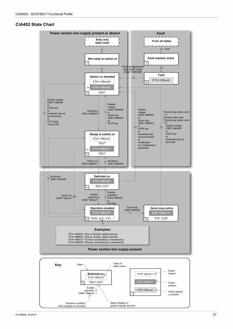
CiA402 State Chart
FaultPower section line supply present or absent
Power section line supply present
Transition conditionwith example of command
Value ofstatus word
Powerabsent
Powerpresent
Status display ongraphic display terminal
StateKey:
Examples:ETA=16#0637: Stop or forward, speed reachedETA=16#8637: Stop or reverse, speed reachedETA=16#0237: Forward, accelerating or deceleratingETA=16#8237: Reverse, accelerating or decelerating
Enableoperation
CMD=16#xxxF
Switched on
Ready to switch on
or
Switched on
Operation enabled
Power absentor present
Enableoperation
CMD=16#xxxF
DisableoperationCMD=16#xxxForfast stop
Quick stopCMD=16#0002
Quick stop active
Switch onCMD=16#xxxF
ShutdownCMD=16#0006
Switch onCMD=16#0007
ShutdownCMD=16#0006
DisablevoltageCMD=16#0000orQuick stopCMD=16#0002 orSTOP keyorfreewheel stopat the terminalsormodificationof a configurationparameter
If Quick stop option code = 2: transition after stop.If Quick stop option code = 6:
Disable voltageCMD=16#0000orSTOP keyorfreewheel stop atterminals
DisablevoltageCMD=16#0000orQuick stopCMD=16#0002 orSTOP key
ShutdownCMD=16#0006
Disable voltageCMD=16#0000orSTOP keyorfreewheel stop at the terminalsorSTO (Safe Torque Off)
or
Switch on disabled
Fault disappeared and faults resetCMD=16#0080
Not ready to switch on
Entry intostate chart
Fault reaction active
From all states
Fault
Fault
S1A28698 03/2010 27

CiA®402 - IEC61800-7 Functional Profile
Description of States
Each state represents an internal reaction by the drive.
This chart will change depending on whether the control word is sent (CMd) or an event occurs (a detected fault, for example).
The drive state can be identified by the value of the status word (EtA).
State Drive internal reaction
1 - Not ready to switch on Initialization starts. This is a transient state invisible to the communication network.
2 - Switch on disabled The drive is inactive.The drive is locked, no power is supplied to the motor.For a separate control section, it is not necessary to supply AC power to the power section.For a separate control section with line contactor, the contactor is not controlled.The configuration and adjustment parameters can be modified.
3 - Ready to switch on Awaiting power section line supply.For a separate control section, it is not necessary to supply AC power to the power section, but the system will expect it in order to change to state “4 - Switched on”.For a separate control section with line contactor, the contactor is not controlled.The drive is locked, no power is supplied to the motor.The configuration and adjustment parameters can be modified.
4 - Switched on The drive is supplied with AC power but is stationary.For a separate control section, the power section line supply must be present.For a separate control section with line contactor, the contactor is controlled.The drive is locked, no power is supplied to the motor.The power stage of the drive is ready to operate, but voltage has not yet been applied to the output.The adjustment parameters can be modified.Modification of a configuration parameter returns the drive to state “2 - Switch on disabled”.
5 - Operation enabled The drive is running.For a separate control section, the power section line supply must be present.For a separate control section with line contactor, the contactor is controlled.The drive is unlocked, power is supplied to the motor.The drive functions are activated and voltage is applied to the motor terminals.However, in the case of an open-loop drive, if the reference is zero or the “Halt” command is applied, no power is supplied to the motor and no torque is applied.[Auto tuning] (tUn) requires an injection of current into the motor. The drive must therefore be in state “5 - Operation enabled” for this command.The adjustment parameters can be modified.The configuration parameters cannot be modified.NOTE: the command “4 - Enable operation” must be taken into consideration only if the channel is valid. In particular, if the channel is involved in the command and the reference, transition 4 will take place only after the reference has been received for the first time.The reaction of the drive to a “Disable operation” command depends on the value of the [Dis. operat opt code] (dOtd) parameter:
- If the [Dis. operat opt code] (dOtd) parameter has the value 0, the drive changes to “4 - Switched on” and stops in freewheel stop.
- If the [Dis. operat opt code] (dOtd) parameter has the value 1, the drive stops on ramp and then changes to “4 - Switched on”.
6 - Quick stop active Emergency stopThe drive performs a fast stop, after which restarting will only be possible once the drive has changed to the “Switch on disabled” state.During fast stop, the drive is unlocked and power is supplied to the motor.The configuration parameters cannot be modified.The condition for transition 12 to state “2 - Switch on disabled” depends on the value of the parameter Quick stop mode (QStd):If the Quick stop mode parameter has the value FST2, the drive stops according to the fast stop ramp and then changes to state “2 - Switch on disabled”.If the Quick stop mode parameter has the value FST6, the drive stops according to the fast stop ramp and then remains in state “6 - Quick stop active” until:
- A “Disable voltage” command is received.- Or the STOP key is pressed.- Or there is a freewheel stop command via the terminals.
28 S1A28698 03/2010

CiA®402 - IEC61800-7 Functional Profile
Summary
7 - Fault reaction active Transient state during which the drive performs an action appropriate to the type of detected fault.The drive function is activated or deactivated according to the type of reaction configured in the detected fault management parameters.
8 - Fault Drive has detected a fault.The drive is locked, no power is supplied to the motor.
State Drive internal reaction
State Power section line supply for separate control section
Power supplied to motor Modification of configuration parameters
1 - Not ready to switch on Not required No Yes
2 - Switch on disabled Not required No Yes
3 - Ready to switch on Not required No Yes
4 - Switched on Required No Yes, return to “2 - Switch on disabled” state
5 - Operation enabled Required Yes, apart from an open-loop drive with a zero reference or in the event of a “Halt” command for an open-loop drive.
No
6 - Quick stop active Required Yes, during fast stop No
7 - Fault reaction active Depends on detected fault management configuration
Depends on detected fault management configuration
-
8 - Fault Not required No Yes
S1A28698 03/2010 29

CiA®402 - IEC61800-7 Functional Profile
Control Word (CMd)
x: Value is of no significance for this command.0 V 1: Command on rising edge.
bit 7 bit 6 bit 5 bit 4 bit 3 bit 2 bit 1 bit 0
Fault reset Reserved (=0) Reserved (=0) Reserved (=0) Enable operation
Quick stop Enable voltage Switch on
0 to 1 transition = Ack. fault
1 = Run command
0 = Emergency stop
Authorization to supply AC power
Contactor control
bit 15 bit 14 bit 13 bit 12 bit 11 bit 10 bit 9 bit 8
MANUFACTURER SPECIFIC Assignable
MANUFACTURER SPECIFIC Assignable
MANUFACTURER SPECIFIC Assignable
MANUFACTURER SPECIFIC Assignable
Manufacturer specific
Reserved (=0) Reserved (=0) Halt
0 = Forward direction asked1= Reverse direction asked
Halt
Command Transition address
Final state bit 7 bit 3 bit 2 bit 1 bit 0 ExamplevalueFault reset Enable
operationQuick stop Enable
voltageSwitch on
Shutdown 2, 6, 8 3 - Ready to switch on
x x 1 1 0 16#0006
Switch on 3 4 - Switched on
x x 1 1 1 16#0007
Enable operation
4 5 - Operation enabled
x 1 1 1 1 16#000F
Disable operation
5 4 - Switched on
x 0 1 1 1 16#0007
Disable voltage
7, 9, 10, 12 2 - Switch on disabled
x x x 0 x 16#0000
Quick stop 11 6 - Quick stop active
x x 0 1 x 16#0002
7, 10 2 - Switch on disabled
Fault reset 15 2 - Switch on disabled
0 V 1 x x x x 16#0080
30 S1A28698 03/2010

CiA®402 - IEC61800-7 Functional Profile
Stop Commands
The “Halt” command enables movement to be interrupted without having to leave the “5 - Operation enabled” state. The stop is performed in accordance with the [Type of stop] (Stt) parameter.
If the “Halt” command is active, power is supplied to the motor and torque can be applied during “Halt” state through DC injection when ADC = CT or LI DCI active.
Regardless of the assignment of the [Type of stop] (Stt) parameter ([Fast stop assign] (FSt), [Ramp stop] (rMP), [Freewheel] (nSt), or [DC injection assign.] (dCI)), the drive remains in the “5 - Operation enabled” state.
A Fast Stop command at the terminals or using a bit of the control word assigned to Fast Stop causes a change to the “4 - Switched on” state. A “Halt” command does not cause this transition.
A Freewheel Stop command at the terminals or using a bit of the control word assigned to Freewheel Stop causes a change to the “2 - Switch on disabled” state. A “Halt” command does not cause this transition.
Assigning Control Word Bits
In the CiA402 profile, fixed assignment of a function input is possible using the following codes:
For example, to assign the DC injection braking to bit 13 of Modbus, simply configure the [DC injection assign.] (dCI) parameter with the [C113] (C113) value.
Bit 11 is assigned by default to the operating direction command [Reverse assign.] (rrS).
Bit Integrated Modbus
bit 11 C111
bit 12 C112
bit 13 C113
bit 14 C114
bit 15 C115
S1A28698 03/2010 31

CiA®402 - IEC61800-7 Functional Profile
Status Word (EtA)
(1) This mask can be used by the PLC program to test the chart state.(2) Detected fault following state “6 - Quick stop active”.x: In this state, the value of the bit can be 0 or 1.
bit 7 bit 6 bit 5 bit 4 bit 3 bit 2 bit 1 bit 0
Warning Switch on disabled
Quick stop Voltage enabled
Fault Operation enabled
Switched on Ready to switch on
Alarm Power section line supply disabled
0 = Emergency stop
Power section line supply present
Fault Running Ready 1 = Awaiting power section line supply
bit 15 bit 14 bit 13 bit 12 bit 11 bit 10 bit 9 bit 8
Manufacturer specificDirection of rotation
MANUFACTURER SPECIFICStop via STOP key
Reserved (=0) Reserved (=0) Internal limit active
Target reached Remote Reserved (=0)
Reference outside limits
Reference reached
Command or reference via network
Status bit 6 bit 5 bit 4 bit 3 bit 2 bit 1 bit 0 ETAmasked by 16#006F (1)
Switch on disabled
Quick stop Voltage enabled
Fault Operation enabled
Switched on Ready to switch on
1 -Not ready to switch on
0 x x 0 0 0 0 -
2 -Switch on disabled
1 x x 0 0 0 0 16#0040
3 -Ready to switch on
0 1 x 0 0 0 1 16#0021
4 -Switched on
0 1 1 0 0 1 1 16#0023
5 -Operation enabled
0 1 1 0 1 1 1 16#0027
6 -Quick stop active
0 0 1 0 1 1 1 16#0007
7 -Fault reaction active
0 x x 1 1 1 1 -
8 -Fault 0 x x 1 0 0 0 16#0008 (2)
or 16#0028
32 S1A28698 03/2010

CiA®402 - IEC61800-7 Functional Profile
Starting Sequence
The command sequence in the state chart depends on how power is being supplied to the drive.
There are three possible scenarios:
(1) The power section supplies the control section.
Power section line supply
Direct Direct Line contactor controlled by the drive
Control section power supply
Not separate (1) Separate Separate
DRIVE
Pow
er s
ectio
n lin
e su
pply
DRIVE
Con
trol s
ectio
n po
wer
sup
ply
Pow
er s
ectio
n lin
e su
pply
DRIVE
Pow
er s
ectio
n lin
e su
pply
Con
trol s
ectio
n po
wer
sup
ply
S1A28698 03/2010 33
CiA®402 - IEC61800-7 Functional Profile
Sequence for a Drive Powered by the Power Section Line Supply
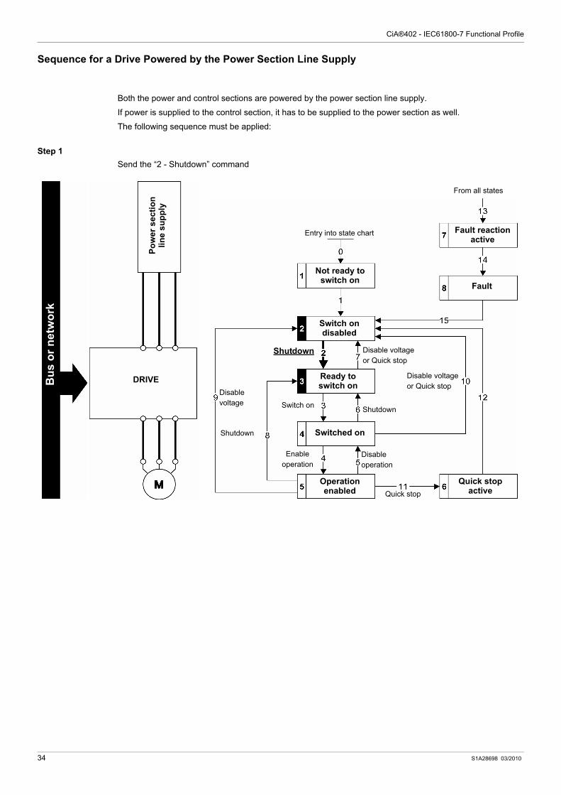
Both the power and control sections are powered by the power section line supply.
If power is supplied to the control section, it has to be supplied to the power section as well.
The following sequence must be applied:
Step 1Send the “2 - Shutdown” command
DRIVE
Pow
er s
ectio
n lin
e su
pply
Bus
or n
etw
ork
Entry into state chart
From all states
Not ready to switch on
Fault reaction active
Fault
Switch on disabled
Ready to switch on
Shutdown Disable voltage or Quick stop
Shutdown
Disable voltage
Shutdown
Switch on
Disable voltage or Quick stop
Switched on
Operation enabled
Quick stop active
Enable operation
Disable operation
Quick stop
34 S1A28698 03/2010

CiA®402 - IEC61800-7 Functional Profile
Step 2• Check that the drive is in the “3 - Ready to switch on” state.• Then send the “4 - Enable operation” command.• The motor can be controlled (send a reference not equal to zero).
NOTE: it is possible, but not necessary, to send the “3 - Switch on” command followed by the “4 - Enable Operation” command to switch successively into the states “3 - Ready to Switch on”, “4 - Switched on” and then “5 - Operation Enabled”. The “4 - Enable operation” command is sufficient.
DRIVE
Pow
er s
ectio
n lin
e su
pply
Bus
or n
etw
ork
Entry into state chart
From all states
Not ready to switch on
Fault reaction active
Fault
Switch on disabled
Ready to switch on
Disable voltage or Quick stop
Shutdown
Disable voltage
Shutdown
Switch on
Disable voltage or Quick stop
Switched on
Operation enabled
Quick stop active
Enable operation
Disable operation
Quick stop
Switch on
S1A28698 03/2010 35

CiA®402 - IEC61800-7 Functional Profile
Sequence for a Drive With Separate Control Section
Power is supplied separately to the power and control sections.
If power is supplied to the control section, it does not have to be supplied to the power section as well.
The following sequence must be applied:
Step 1• The power section line supply is not necessarily present.• Send the “2 - Shutdown” command
DRIVE
Pow
er s
ectio
n lin
e su
pply
Bus
or n
etw
ork
Con
trol
sec
tion
po
wer
sup
ply
From all states
Not ready to switch on
Fault reaction active
Fault
Switch on disabled
Ready to switch on
Shutdown Disable voltage or Quick stop
Shutdown
Disable voltage
Shutdown
Switch on
Disable voltageor Quick stop
Switched on
Operation enabled
Quick stop active
Enable operaton
Disable operation
Quick stop
Entry into state chart
36 S1A28698 03/2010

CiA®402 - IEC61800-7 Functional Profile
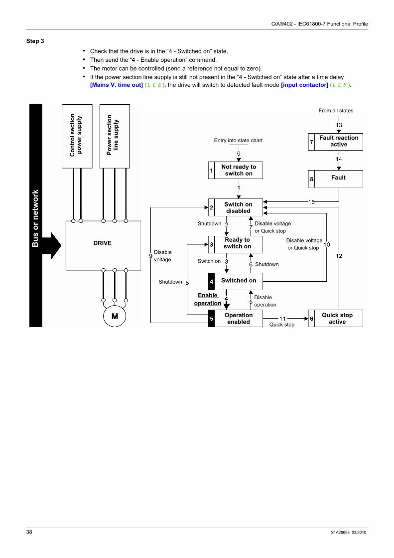
Step 2• Check that the drive is in the “3 - Ready to switch on” state.• Check that the power section line supply is present (“Voltage enabled” of the status word).
• Send the “3 - Switch on” command
Power section line supply Terminal display Status word
Absent nLP 16#pp21
Present rdY 16#pp31
DRIVE
Pow
er s
ectio
n lin
e su
pply
Bus
or n
etw
ork
Con
trol
sec
tion
po
wer
sup
ply
Entry into state chart
From all states
Not ready to switch on
Fault reaction active
Fault
Switch on disabled
Ready to switch on
Shutdown Disable voltage or Quick stop
Shutdown
Disable voltage
Shutdown
Disable voltageor Quick stop
Switched on
Operation enabled
Quick stop active
Enable operation
Disable operation
Quick stop
Switch on
S1A28698 03/2010 37
CiA®402 - IEC61800-7 Functional Profile
Step 3• Check that the drive is in the “4 - Switched on” state.• Then send the “4 - Enable operation” command.• The motor can be controlled (send a reference not equal to zero).• If the power section line supply is still not present in the “4 - Switched on” state after a time delay
[Mains V. time out] (LCt), the drive will switch to detected fault mode [input contactor] (LCF).
DRIVE
Pow
er s
ectio
n lin
e su
pply
Bus
or n
etw
ork
Con
trol
sec
tion
po
wer
sup
ply
Entry into state chart
From all states
Not ready to switch on
Fault reaction active
Fault
Switch on disabled
Ready to switch on
Disable voltage or Quick stop
Shutdown
Disable voltage
Shutdown
Switch on
Disable voltage or Quick stop
Switched on
Operation enabled
Quick stop active
Disable operation
Quick stop
Shutdown
Enable operation
38 S1A28698 03/2010

CiA®402 - IEC61800-7 Functional Profile
Sequence for a Drive with Line Contactor Control
Power is supplied separately to the power and control sections.
If power is supplied to the control section, it does not have to be supplied to the power section as well. The drive controls the line contactor.
The following sequence must be applied:
Step 1• The power section line supply is not present as the line contactor is not being controlled.• Send the “2 - Shutdown” command
DRIVE
Pow
er s
ectio
n lin
e su
pply
Bus
or n
etw
ork
Con
trol
sec
tion
po
wer
sup
ply Entry into state chart
From all states
Not ready to switch on
Fault reaction active
Fault
Switch on disabled
Ready to switch on
Shutdown Disable voltage or Quick stop
Shutdown
Disable voltage
Shutdown
Switch on
Disable voltage or Quick stop
Switched on
Operation enabled
Quick stop active
Enable operation
Disable operation
Quick stop
S1A28698 03/2010 39

CiA®402 - IEC61800-7 Functional Profile
Step 2• Check that the drive is in the “3 - Ready to switch on” state.• Send the “3 - Switch on” command, which will close the line contactor and switch on the power section line
supply.
DRIVE
Pow
er s
ectio
n lin
e su
pply
Bus
or n
etw
ork
Con
trol
sec
tion
po
wer
sup
ply
Entry into state chart
From all states
Not ready to switch on
Fault reaction active
Fault
Switch on disabled
Ready to switch on
Shutdown Disable voltageor Quick stop
Shutdown
Disable voltage
Shutdown
Switch on
Disable voltage or Quick stop
Switched on
Operation enabled
Quick stop active
Enable operation
Disableoperation
Quick stop
40 S1A28698 03/2010

S1A28698 03/2010
Software Setup with Unity (M340)
6
Software Setup with Unity (M340)What's in this Chapter?This chapter contains the following topics:
Topic Page
Introduction 42
Drive Configuration 43
Modbus Master Configuration 44
41

Software Setup with Unity (M340)
Introduction
Here is an example of an application that shows how to control an ATV32 with a M340 PLC equipped with a Modbus master serial port. The operator can control the drive directly from Unity. The version of Unity used here is Unity Pro XL V4.0.
In the example, the communication scanner of the ATV32 is used. The PLC will send the command and the speed reference to the ATV32 and will read the status word and the actual speed of the drive.
M340 with P342010 CPU
42 S1A28698 03/2010

Software Setup with Unity (M340)
Drive Configuration
Factory SettingBefore configuring the drive, it’s strongly advised to make a factory setting. Goto to:• [1.3 CONFIGURATION] (COnF) menu,• [FACTORY SETTINGS] (FCS-) sub-menu.
Then configure the following parameters:• [PARAMETER GROUP LIST] (FrY-) = [All] (All)• [Goto FACTORY SETTINGS] (GFS) = enter
Command ConfigurationTo control the drive with a Modbus Master, it is necessary to select Modbus as command channel active.
Goto to:• [1.3 CONFIGURATION] (COnF),• [FULL] (FULL)• [COMMAND] (CtL-) menu
And then configure:• [Ref.1 channel] (Fr1) parameter to [Modbus] (Mdb) value.
Communication ConfigurationSelect the Modbus address in the menu:• [1.3 CONFIGURATION] (COnF)• [FULL] (FULL)• [COMMUNICATION] (COM-) menu• [MODBUS NETWORK] (Md1-)
And then configure:• [Modbus address] (Add) parameter to [2] (2) value.
The drive must be restarted in order to take into account the Modbus address.
S1A28698 03/2010 43
Software Setup with Unity (M340)
Modbus Master Configuration
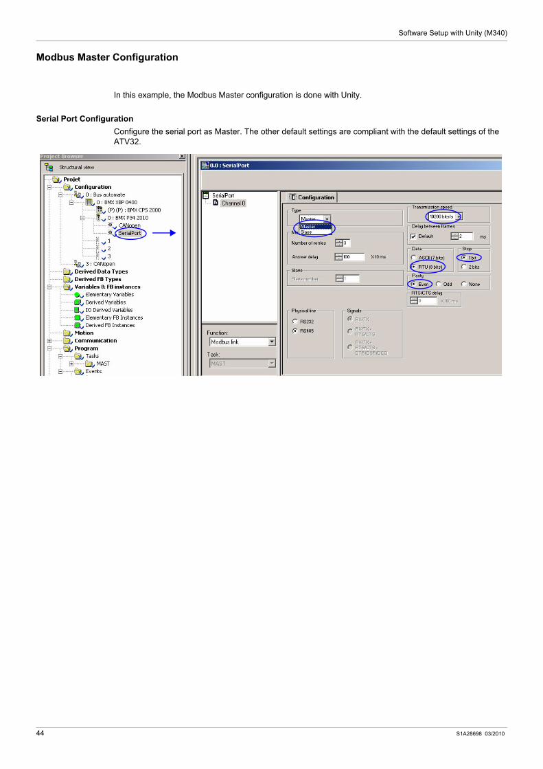
In this example, the Modbus Master configuration is done with Unity.
Serial Port ConfigurationConfigure the serial port as Master. The other default settings are compliant with the default settings of the ATV32.
44 S1A28698 03/2010

Software Setup with Unity (M340)
Data Structure DeclarationCreate the following table (DevicePath). DevicePath describes the path to the device including its slave address.
Then create the 4 others tables as arrays from 0 to 3 of integer.
1
23
45
6
2
1
S1A28698 03/2010 45

Software Setup with Unity (M340)
As all the tables declared are dynamic (no fixed address), it is necessary in the project setting to «Allows dynamic array» and to «Directly represented array variables». The parametrization must be done in the menu «Tool», «Project Settings», «Language extensions» window.
1
2
3
4
5
46 S1A28698 03/2010
Software Setup with Unity (M340)
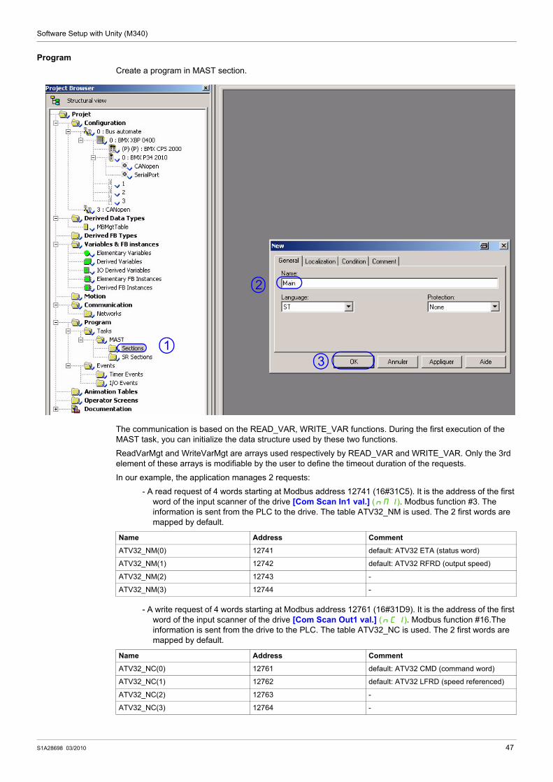
ProgramCreate a program in MAST section.
The communication is based on the READ_VAR, WRITE_VAR functions. During the first execution of the MAST task, you can initialize the data structure used by these two functions.
ReadVarMgt and WriteVarMgt are arrays used respectively by READ_VAR and WRITE_VAR. Only the 3rd element of these arrays is modifiable by the user to define the timeout duration of the requests.
In our example, the application manages 2 requests:
- A read request of 4 words starting at Modbus address 12741 (16#31C5). It is the address of the first word of the input scanner of the drive [Com Scan In1 val.] (nM1). Modbus function #3. The information is sent from the PLC to the drive. The table ATV32_NM is used. The 2 first words are mapped by default.
- A write request of 4 words starting at Modbus address 12761 (16#31D9). It is the address of the first word of the input scanner of the drive [Com Scan Out1 val.] (nC1). Modbus function #16.The information is sent from the drive to the PLC. The table ATV32_NC is used. The 2 first words are mapped by default.
1
2
3
Name Address Comment
ATV32_NM(0) 12741 default: ATV32 ETA (status word)
ATV32_NM(1) 12742 default: ATV32 RFRD (output speed)
ATV32_NM(2) 12743 -
ATV32_NM(3) 12744 -
Name Address Comment
ATV32_NC(0) 12761 default: ATV32 CMD (command word)
ATV32_NC(1) 12762 default: ATV32 LFRD (speed referenced)
ATV32_NC(2) 12763 -
ATV32_NC(3) 12764 -
S1A28698 03/2010 47

Software Setup with Unity (M340)
48 S1A28698 03/2010

S1A28698 03/2010
Software Setup with SoMachine (M238)
7
Software Setup with SoMachine (M238)What's in this Chapter?This chapter contains the following topics:
Topic Page
Introduction 50
Drive Configuration 51
Modbus Master Configuration 52
49

Software Setup with SoMachine (M238)
Introduction
Here is an example of an application that shows how to control an ATV32 with a M238 PLC equipped with a Modbus port. The operator can control the drive directly from SoMachine.
In the example, the communication scanner of the ATV32 is used. The PLC will send the command and the speed reference to the ATV32 and will read the status word and the actual speed of the drive.
PLC: TM238LFDC24DT
50 S1A28698 03/2010

Software Setup with SoMachine (M238)
Drive Configuration
Factory SettingBefore configuring the drive, it’s strongly advised to make a factory setting. Goto to:• [1.3 CONFIGURATION] (COnF) menu,• [FACTORY SETTINGS] (FCS-) sub-menu.
Then configure the following parameters:• [PARAMETER GROUP LIST] (FrY) = [All] (All)• [Goto FACTORY SETTINGS] (GFS) = enter
Command ConfigurationTo control the drive with a Modbus Master, it is necessary to select Modbus as command channel active.
Goto to:• [1.3 CONFIGURATION] (COnF),• [FULL] (FULL)• [COMMAND] (CtL-) menu
And then configure:• [Ref. 1 channel] (Fr1) parameter to [Modbus] (Mdb) value.
Communication ConfigurationSelect the Modbus address in the menu:• [1.3 CONFIGURATION] (COnF)• [FULL] (FULL)• [COMMUNICATION] (COM-) menu• [MODBUS NETWORK] (Md1-)
And then configure:• [Modbus address] (Add) parameter to [2] (2) value.
The drive must be restarted in order to take into account the Modbus address.
S1A28698 03/2010 51

Software Setup with SoMachine (M238)
Modbus Master Configuration
In this example, the Modbus master configuration is done with SoMachine.
Serial Port ConfigurationConfigure the serial port as Master.
52 S1A28698 03/2010

Software Setup with SoMachine (M238)
Add device Modbus IOScanner Schneider Electric
The other default settings are compliant with the default settings of the ATV32.
2
1
S1A28698 03/2010 53

Software Setup with SoMachine (M238)
Configure the ATV32 slave address.
Check the transmission mode (RTU) and the timeout.
Read/Write Multiple Registers Function (#23)The communication is based on the READ/WRITE Multiple registers function.
In our example, the application manages 1 function (#23) which includes 2 requests:
- A read request of 4 words starting at Modbus address 12741 (16#31C5). It is the address of the first word of the input scanner of the drive [Com Scan In1 val.] (nM1). The information is sent from the PLC to the drive. The 2 first words are mapped by default.
- A write request of 4 words starting at Modbus address 12761 (16#31D9). It is the address of the first word of the input scanner of the drive [Com Scan Out1 val.] (nC1). The information is sent from the drive to the PLC. The 2 first words are mapped by default.
Name Address Comment
ATV32_NM(0) 12741 default: ATV32 ETA (status word)
ATV32_NM(1) 12742 default: ATV32 RFRD (output speed)
ATV32_NM(2) 12743 -
ATV32_NM(3) 12744 -
Name Address Comment
ATV32_NC(0) 12761 default: ATV32 CMD (command word)
ATV32_NC(1) 12762 default: ATV32 LFRD (speed referenced)
ATV32_NC(2) 12763 -
ATV32_NC(3) 12764 -
54 S1A28698 03/2010

Software Setup with SoMachine (M238)
- Select the Read/Write Multiple Registers function (1),- Enter the address of the first read word and the length of the table (2),- Enter the address of the first write word and the length of the table (3),- Validate the function with «Enter» (4).
Use the «Modbus Master I/O Mapping» to exchange data with the drive.
2
1
4
3
S1A28698 03/2010 55

56
Modbus Functions
8
Modbus FunctionsWhat's in this Chapter?This chapter contains the following topics:
Topic Page
Modbus Protocol 57
Supported Modbus Functions 58
S1A28698 03/2010
Modbus Functions
Modbus Protocol
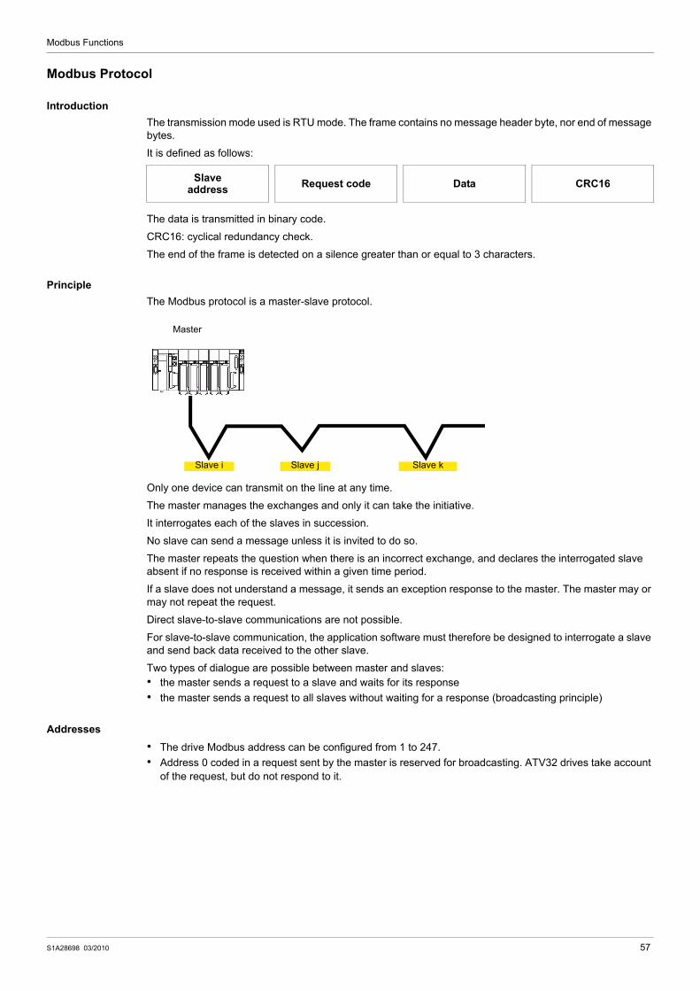
IntroductionThe transmission mode used is RTU mode. The frame contains no message header byte, nor end of message bytes.
It is defined as follows:
The data is transmitted in binary code.
CRC16: cyclical redundancy check.
The end of the frame is detected on a silence greater than or equal to 3 characters.
PrincipleThe Modbus protocol is a master-slave protocol.
Only one device can transmit on the line at any time.
The master manages the exchanges and only it can take the initiative.
It interrogates each of the slaves in succession.
No slave can send a message unless it is invited to do so.
The master repeats the question when there is an incorrect exchange, and declares the interrogated slave absent if no response is received within a given time period.
If a slave does not understand a message, it sends an exception response to the master. The master may or may not repeat the request.
Direct slave-to-slave communications are not possible.
For slave-to-slave communication, the application software must therefore be designed to interrogate a slave and send back data received to the other slave.
Two types of dialogue are possible between master and slaves:• the master sends a request to a slave and waits for its response• the master sends a request to all slaves without waiting for a response (broadcasting principle)
Addresses• The drive Modbus address can be configured from 1 to 247.• Address 0 coded in a request sent by the master is reserved for broadcasting. ATV32 drives take account
of the request, but do not respond to it.
Slave address Request code Data CRC16
Master
Slave i Slave j Slave k
S1A28698 03/2010 57

Modbus Functions
Supported Modbus Functions
IntroductionThe Altivar 32 supports the following Modbus functions:
Function name Code Description Remarks
Read Holding Registers 0316#03
Read N output words Max PDU length: 63 words
Write One Output Word 0616#06
Write one output word -
Write Multiple Registers 1616#10
Write N output word Max PDU length: 61 words
Read/write Multiple Registers 2316#17
Read/write multiple registers Max PDU length: 20 words (W), 20 words (R)
(Sub-function)Read Device Identification
43/1416#2B16#0E
Encapsulated interface transport / Read device identification
-
Diagnostics 08 Diagnostics -
58 S1A28698 03/2010
Modbus Functions
Read Holding RegistersRequest
Response
(1) N: Quantity of Registers
Error
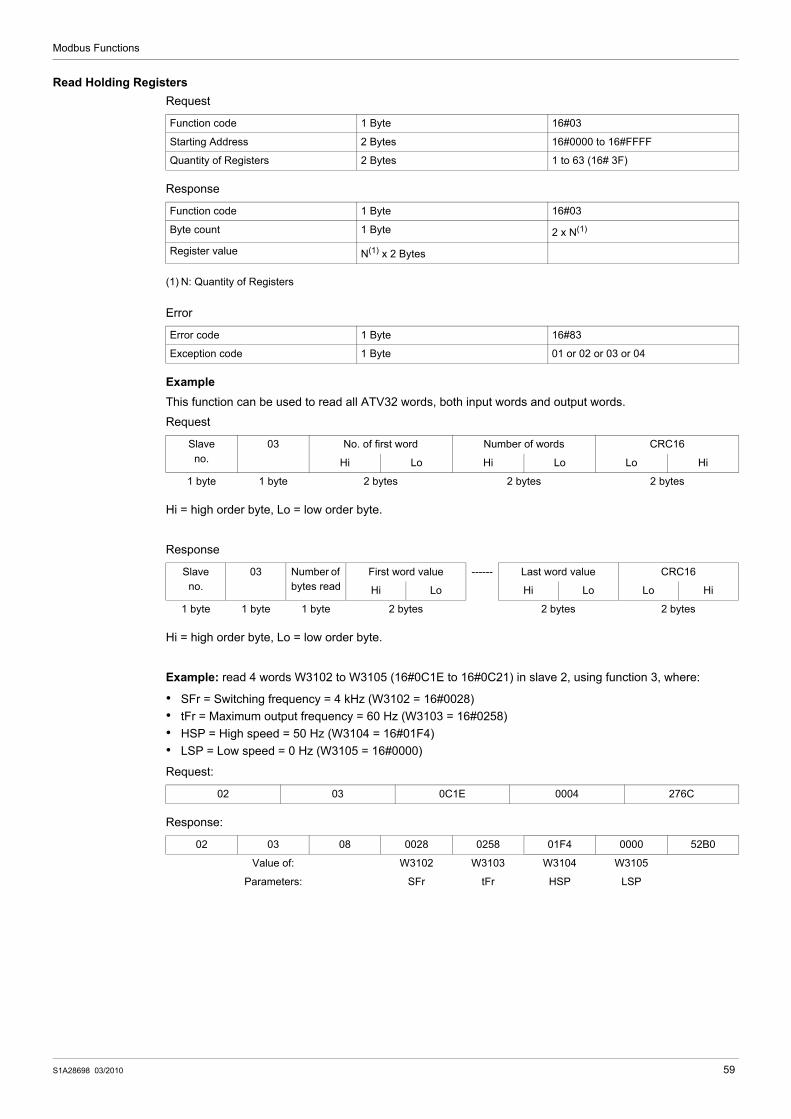
ExampleThis function can be used to read all ATV32 words, both input words and output words.
Request
Hi = high order byte, Lo = low order byte.
Response
Hi = high order byte, Lo = low order byte.
Example: read 4 words W3102 to W3105 (16#0C1E to 16#0C21) in slave 2, using function 3, where:
• SFr = Switching frequency = 4 kHz (W3102 = 16#0028)• tFr = Maximum output frequency = 60 Hz (W3103 = 16#0258)• HSP = High speed = 50 Hz (W3104 = 16#01F4)• LSP = Low speed = 0 Hz (W3105 = 16#0000)
Request:
Response:
Function code 1 Byte 16#03
Starting Address 2 Bytes 16#0000 to 16#FFFF
Quantity of Registers 2 Bytes 1 to 63 (16# 3F)
Function code 1 Byte 16#03
Byte count 1 Byte 2 x N(1)
Register value N(1) x 2 Bytes
Error code 1 Byte 16#83
Exception code 1 Byte 01 or 02 or 03 or 04
Slaveno.
03 No. of first word Number of words CRC16
Hi Lo Hi Lo Lo Hi
1 byte 1 byte 2 bytes 2 bytes 2 bytes
Slaveno.
03 Number of bytes read
First word value ------ Last word value CRC16
Hi Lo Hi Lo Lo Hi
1 byte 1 byte 1 byte 2 bytes 2 bytes 2 bytes
02 03 0C1E 0004 276C
02 03 08 0028 0258 01F4 0000 52B0
Value of: W3102 W3103 W3104 W3105
Parameters: SFr tFr HSP LSP
S1A28698 03/2010 59

Modbus Functions
Write One Output WordRequest
Response
Error
ExampleRequest and response (the frame format is identical)
Example: write value 16#000D in word W9001 (16#2329) in slave 2 (ACC = 1.3 s).
Function code 1 Byte 16#06
Register Address 2 Bytes 16#0000 to 16#FFFF
Register value 2 Bytes 16#0000 to 16#FFFF
Function code 1 Byte 16#06
Register Address 2 Bytes 16#0000 to 16#FFFF
Register value 2 Bytes 16#0000 to 16#FFFF
Error code 1 Byte 16#86
Exception code 1 Byte 01 or 02 or 03 or 04
Slaveno.
06 Word number Value of word CRC16
Hi Lo Hi Lo Lo Hi
1 byte 1 byte 2 bytes 2 bytes 2 bytes
Request and response 02 06 2329 000D 9270
60 S1A28698 03/2010

Modbus Functions
Write Multiple RegisterRequest
Response
Example: Write values 20 and 30 to words W9001 and W9002 on slave 2 (acceleration time = 2 s and deceleration time = 3 s)
Request
Response
(hexadecimal values)
Slave no. 10 No. of first word Number of words Number of bytes
Value of first word -- CRC16
Hi Lo Hi Lo Hi Lo Lo Hi
1 byte 1 byte 2 bytes 2 bytes 1 byte 2 bytes 2 bytes
Slave no. 10 No. of first word Number of words CRC16
Hi Lo Hi Lo Lo Hi
1 byte 1 byte 2 bytes 2 bytes 2 bytes
Slave no.
Request code
No. of first word
Number of words
Number of bytes
Value of first word
Value of second word
CRC16
Hi Lo Hi Lo Hi Lo Hi Lo Lo Hi
02 10 23 29 00 02 04 00 14 00 1E 73 A4
Slave no. Response code No. of first word Number of words CRC16
Hi Lo Hi Lo Lo Hi
02 10 23 29 00 02 9B B7
S1A28698 03/2010 61

Modbus Functions
Read/write Multiple Registers
Example
Description Length in byte Value Comment
Function code 1 16#17 -
Read starting address 2 16#XXXX Always Modbus address
Quantity 2 16#03 Contain number of holding registers to be read
Write starting address 2 16#XXXX Always Modbus address
Quantity 2 16#03 Contain number of holding registers to be written
Write Byte count 1 16#06 The byte count specifies the number of bytes to follow in the field Write Register Value
Write Registers Value 6 16#XXXXXXXXXXXX
Value to be written respectively in NCA1 to NCA3, so the configured example:CMD, LFRD, CMI
Slave n° FunctionCode
Read startingAddress HI
Read startingAddress LOW
Qty Write startingAddress HI
Write startingAddress LOW
Qty
2 byte 1 byte 1 byte 2 byte1 byte1 byte1 byte1 byte
1 byte 1 byte1 byte1 byte1 byte
Write bytecount
Writing Value 1 HI
Value 1 Lo Value 1 HIWriting Value 1.. 2... 3...n ... CRC16
2 byte
62 S1A28698 03/2010

Modbus Functions
Read Device Identification
ExampleDefault values to be detailed
Request
Response
The total response size equals 49 bytes
The three objects contained in the response correspond to the following objects:• Object no. 1: Manufacturer name (always “Schneider Electric”, ie. 18 bytes).• Object no. 2: Device reference (ASCII string; for example: “ATV32HU75M3”, ie. 11 bytes).• Object no. 3: Device version, in “MMmm” format where “MM” represents the determinant and “mm” the
subdeterminant (4-bytes ASCII string; for example: “0201” for version 2.1).
NOTE: The response to function 43 may be negative; in this case, the response located at the top of the next page is sent by the Altivar 32 rather than the response described above.
ID Name / Description Type
16#00 VendorName ASCII String
16#01 ProductCode ASCII String
16#02 MajorMinorRevision ASCII String
16#04 ProductName ASCII String
Slaveno.
2B Type of MEI0E
ReadDeviceId01
Object Id00
CRC16
Lo Hi
1 byte 1 byte 1 byte 1 byte 1 byte 2 bytes
Slaveno.
2B Type of MEI0E
ReadDeviceId01
Degree of conformity02
-------
1 byte 1 byte 1 byte 1 byte 1 byte
------- Number of additional frames00
Next object Id00
Number of objects03
-------
1 byte 1 byte 1 byte
------- Id of object no. 100
Length of object no. 112
Value of object no. 1“Schneider Electric”
-------
1 byte 1 byte 18 bytes
------- Id of object no. 201
Length of object no. 20B
Value of object no. 2“ATV32HU75M3”
-------
1 byte 1 byte 11 bytes
------- Id of object no. 302
Length of object no. 304
Value of object no. 3“0201”
-------
1 byte 1 byte 04 bytes
------- CRC16
Lo Hi
1 byte 1 byte
S1A28698 03/2010 63

Modbus Functions
DiagnosticsSubcode 16#00: EchoThis function asks the slave being interrogated to echo (return) the message sent by the master in its entirety.
Subcode 16#0A: Counter resetThis function resets all the counters responsible for monitoring a slave’s exchanges.
Subcode 16#0C: Read message counter responsible for counting messages received with checksum errors
Subcode 16#0E: Read message counter responsible for counting messages addressed to slave
Read a word indicating the total number of messages addressed to the slave, regardless of type (excluding broadcast messages).
Request and response
Example: Values 16#31 and 16#32 echoed by slave 4
Request and response (if function successful)
(hexadecimal values)
Slave no. 08 Subcode Data CRC16
Hi Lo Hi Lo Lo Hi
1 byte 1 byte 2 bytes N bytes 2 bytes
Subcode Request data Response data Function executed
00 XX YY XX YY Echo
0A 00 00 00 00 Counter reset
0C 00 00 XX YY(= counter value)
Read message counter responsible for counting messages received with checksum errors
0E 00 00 XX YY(= counter value)
Read message counter responsible for counting messages addressed to slave
Slave no. Request code or Response code
Subcode Value of 1st byte Value of 2nd byte CRC16
Hi Lo Lo Hi
04 08 00 00 31 32 74 1B
64 S1A28698 03/2010

ATV32_Modbus Manual_S1A28698_01
03/2010