audi a7 sportbackdtms-audi.faw-vw.com/audidtms/20120625/eed6b9869093765cb08170… · the self study...
TRANSCRIPT
Audi
Audi
Vorsprung durch Technik
Service Training
47
8
Audi A7 Sportback
All rights reserved.
Technical specifi cations are subject to
change.
Copyright
AUDI AG
I/VK-35
AUDI AG
D-85045 Ingolstadt
Technical status 09/11
Printed in Germany
A10.5S00.71.20
Self Study Programme 478

2
The Audi A7 Sportback is an entirely new class of vehicle. It unites
the purist elegance of a saloon, the well-defi ned functionality of an
Avant and the passionate dynamism of a coupé.
The new Audi A7 Sportback oozes enthusiasm. Above the accentu-
ated wheel arches, a prominently sharp dynamic line extends along
the entire length of the vehicle. It imbues the Audi A7 Sportback
with a unique "stealth" look. The perfect balance of puristic light-
ness and fl owing lines creates a new statement of dynamism and
elegance.
The striking trailing edge interacts harmoniously with the spoiler
edge to provide a dynamic fi nishing touch to the muscular rear
end. The innovative vehicle concept with its wide-opening rear
hatch in coupé-like style is impressive not just because of its
unusual design. The Audi single-frame radiator grille is trimmed
with high-quality horizontal chrome struts and conveys an aura of
elegance and progressiveness.
This re-interpretation of the radiator grille gives the headlights
even more presence and character. The interior concept of the
Audi A7 Sportback cossets the driver and passengers, giving them
a feeling of complete security.
The cockpit is driver-oriented in design, i.e. the centre console
leans towards the driver. Attractive inlays with continuous lines
provide accentuation in the interior.
The Audi A7 Sportback has powerful yet effi cient FSI, TFSI and TDI
engines. The quattro permanent all-wheel drive delivers this power
to the road superbly. The optional quattro with sport diff erential
distributes drive power variably to the individual wheels, giving
enhanced driving dynamics, agility and traction.
Nothing is more inspiring than a blank sheet of paper. A car came
into being on one: contemporary, fascinating, new.
The Audi A7 Sportback.
Learning objectives of this Self Study Programme:
This Self-Study Programme provides you with general information
about the Audi A7 Sportback. After you have worked your way
through this Self Study Programme, you will be able to answer the
following questions:
• From which types of steel is the body built?
• Which engines and which new features are fi tted?
• How is drive force distributed?
• With which type of steering is the Audi A7 Sportback fi tted?
• How is Innovative Thermal Management implemented in the
engines?
• How is the head-up display projected onto the windscreen?
• What does the speed limit indicator display?
• Which sound systems are integrated?
478_028
3
!
IntroductionIn brief _______________________________________________________________________________________________________________________________________________________ 4
BodyIntroduction _________________________________________________________________________________________________________________________________________________ 6
Body structure _______________________________________________________________________________________________________________________________________________ 8
Occupant protectionOverview ____________________________________________________________________________________________________________________________________________________10
Components ________________________________________________________________________________________________________________________________________________11
Engine2.8l V6 FSI engine _________________________________________________________________________________________________________________________________________12
3.0l V6 TFSI engine ________________________________________________________________________________________________________________________________________16
3.0l V6 TDI engine (2nd generation) _____________________________________________________________________________________________________________________20
Innovative Thermal Management (ITM) _________________________________________________________________________________________________________________24
Fuel delivery unit ___________________________________________________________________________________________________________________________________________26
Exhaust systems ___________________________________________________________________________________________________________________________________________26
Power transmissionSummary of new features _________________________________________________________________________________________________________________________________28
New features of the 7 speed dual clutch gearbox 0B5 (S tronic) ______________________________________________________________________________________30
quattro powertrain on the Audi A7 Sportback __________________________________________________________________________________________________________32
Self-locking centre diff erential with asymmetrical-dynamic torque split ____________________________________________________________________________34
Running gearIntroduction ________________________________________________________________________________________________________________________________________________40
Axles _________________________________________________________________________________________________________________________________________________________41
adaptive air suspension (aas) _____________________________________________________________________________________________________________________________42
Steering system ____________________________________________________________________________________________________________________________________________43
Brake system _______________________________________________________________________________________________________________________________________________44
adaptive cruise control (ACC) _____________________________________________________________________________________________________________________________45
Wheels and tyres ___________________________________________________________________________________________________________________________________________45
Electrical systemHead-up display ____________________________________________________________________________________________________________________________________________46
Speed limit display _________________________________________________________________________________________________________________________________________48
Audi active lane assist _____________________________________________________________________________________________________________________________________51
Audi drive select ____________________________________________________________________________________________________________________________________________52
Topology ____________________________________________________________________________________________________________________________________________________56
Air conditioningIntroduction ________________________________________________________________________________________________________________________________________________58
Operation ___________________________________________________________________________________________________________________________________________________59
InfotainmentInstallation locations of the infotainment control units _______________________________________________________________________________________________60
MMI radios and navigation systems ______________________________________________________________________________________________________________________61
MMI display _________________________________________________________________________________________________________________________________________________62
Sound systems _____________________________________________________________________________________________________________________________________________63
ServiceInspection and maintenance ______________________________________________________________________________________________________________________________64
Special tools and workshop equipment __________________________________________________________________________________________________________________65
AnnexSelf Study Programmes ___________________________________________________________________________________________________________________________________67
The Self Study Programme teaches a basic knowledge of the design and functions of new models, new auto-
motive components or new technologies.
It is not a Repair Manual! Figures are given for explanatory purposes only and refer to the data valid at the
time of preparation of the SSP.
For maintenance and repair work, always refer to the current technical literature.
Note
Reference
– Revision status 09/2011
Contents

4
1644
14
20
1911
1635
2139
936 11192914
4969
68
9
In brief
478_029
478_031
478_030
Introduction
5
91
6
14
21
14
52
1197
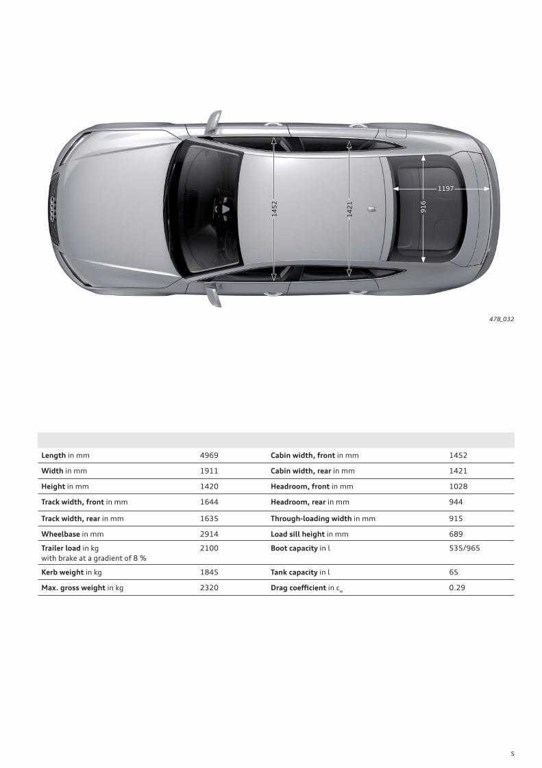
Length in mm 4969 Cabin width, front in mm 1452
Width in mm 1911 Cabin width, rear in mm 1421
Height in mm 1420 Headroom, front in mm 1028
Track width, front in mm 1644 Headroom, rear in mm 944
Track width, rear in mm 1635 Through-loading width in mm 915
Wheelbase in mm 2914 Load sill height in mm 689
Trailer load in kg
with brake at a gradient of 8 %
2100 Boot capacity in l 535/965
Kerb weight in kg 1845 Tank capacity in l 65
Max. gross weight in kg 2320 Drag coeffi cient in cw
0.29
478_032

6
Introduction
The body of the Audi A7 Sportback is of hybrid construction. In this
lightweight construction concept, aluminium components are used
in addition to sheet-metal parts.
In addition to mild, high-strength, modern high-strength and
ultra-high-strength sheet-steel parts, the bodyshell has four
aluminium castings. These are the front strut mountings and the
hinge mountings for attaching the rear hatch.
Body

7
Key:
Mild steel
High-strength steel
Modern high-strength steel
Ultra-high-strength steel
Ultra-high-strength steel (hot-formed)
Cast aluminium
478_094

8
Body structure
The use of ultra-high-strength hot-formed components on the
Audi A7 Sportback helps to enhance body rigidity and crash safety
in particular.
The following components and assemblies, among others, are
manufactured from this type of material:
B-post
The B post and the striker plate are partially tempered in the
forming process. The component is very hard at the top end and
softer below a narrow transition zone. This allows the forces
arising during a side impact to be absorbed eff ectively.
Side member
The rear end employs a similar structural solution. The side
member is manufactured from tailored blanks. It is made of
high-strength sheet metal at the rear end and joins up with an
ultra-high-strength hot-formed component on the side facing the
occupant cell. Both sheet metal blanks are butt joined by laser
welding before they are formed.
• Front side member reinforcement
• Bulkhead
• A post and roof frame side
• B-post
• Chassis rail (sill)
• Front seat cross member
• Tunnel reinforcement
• Rear side member
Body attachments
To reduce vehicle weight, attachments like the front and rear
bumper mounts, wings, strut brace, doors and fl aps are made from
aluminium.
Key:
Ultra-high-strength steel (hot-formed)
High-strength areas in the B post and side member
Steel
478_067
Aluminium panels
Aluminium castings
Extruded aluminium sections
9
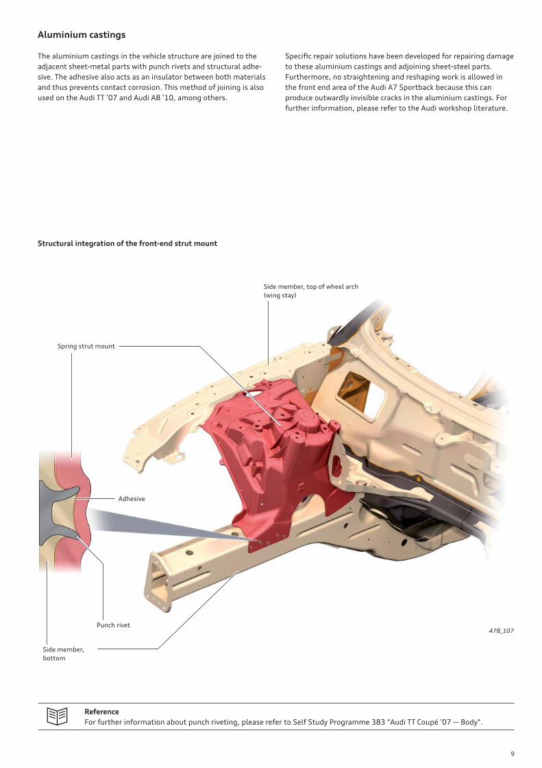
Aluminium castings
The aluminium castings in the vehicle structure are joined to the
adjacent sheet-metal parts with punch rivets and structural adhe-
sive. The adhesive also acts as an insulator between both materials
and thus prevents contact corrosion. This method of joining is also
used on the Audi TT ’07 and Audi A8 ’10, among others.
Specifi c repair solutions have been developed for repairing damage
to these aluminium castings and adjoining sheet-steel parts.
Furthermore, no straightening and reshaping work is allowed in
the front end area of the Audi A7 Sportback because this can
produce outwardly invisible cracks in the aluminium castings. For
further information, please refer to the Audi workshop literature.
Reference
For further information about punch riveting, please refer to Self Study Programme 383 "Audi TT Coupé ’07 — Body".
478_107
Structural integration of the front-end strut mount
Side member, top of wheel arch
(wing stay)
Side member,
bottom
Spring strut mount
Punch rivet
Adhesive

10
Overview
On the following pages you will fi nd a summary of the occupant
protection system in the Audi A7 Sportback.
The illustration in the chapter "Occupant protection" is a schematic
diagram to aid understanding.
Additional equipment
The vehicle can optionally be equipped with rear side airbags and/
or a keyswitch for deactivating the front passenger airbag with
accompanying warning lamp.
Due to the diff erent statutory provisions and requirements con-
cerning car makers in the various markets, equipment is subject to
change. This applies to the US American market in particular.
Reference
For further information about the occupant protection system of the Audi A7 Sportback, please refer to Self Study Pro-
gramme 484 "Audi A7 Sportback Occupant Protection, Infotainment, Air Conditioning".
Occupant protection
11
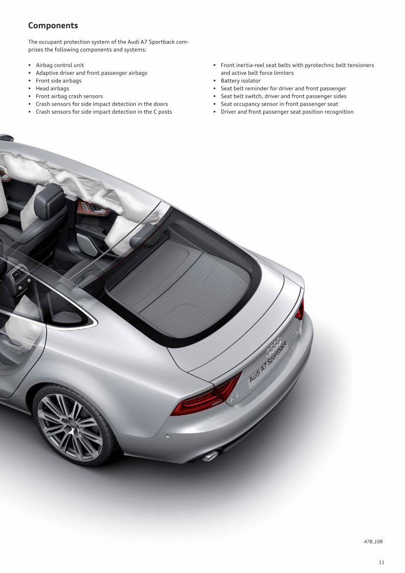
Components
The occupant protection system of the Audi A7 Sportback com-
prises the following components and systems:
• Airbag control unit
• Adaptive driver and front passenger airbags
• Front side airbags
• Head airbags
• Front airbag crash sensors
• Crash sensors for side impact detection in the doors
• Crash sensors for side impact detection in the C posts
• Front inertia-reel seat belts with pyrotechnic belt tensioners
and active belt force limiters
• Battery isolator
• Seat belt reminder for driver and front passenger
• Seat belt switch, driver and front passenger sides
• Seat occupancy sensor in front passenger seat
• Driver and front passenger seat position recognition
478_108
12
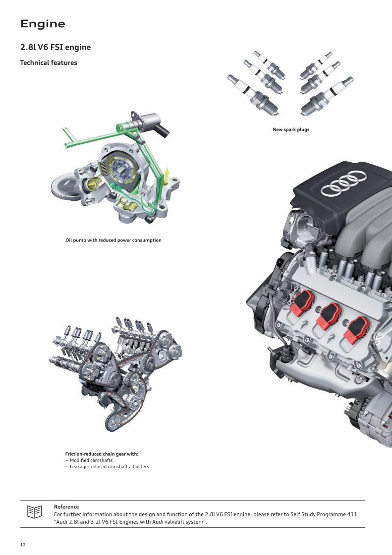
2.8l V6 FSI engine
Technical features
Reference
For further information about the design and function of the 2.8l V6 FSI engine, please refer to Self Study Programme 411
"Audi 2.8l and 3.2l V6 FSI Engines with Audi valvelift system".
Oil pump with reduced power consumption
Friction-reduced chain gear with:
− Modifi ed camshafts
− Leakage-reduced camshaft adjusters
New spark plugs
Engine

13
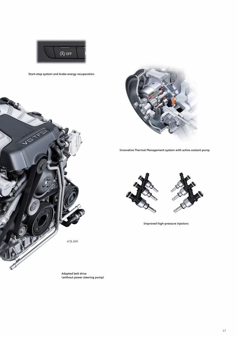
Start-stop system and brake energy recuperation
Innovative Thermal Management system with active coolant pump
Adapted belt drive
(without power steering pump)
Improved high-pressure injectors
478_121

14
478_066
Specifi cations
Torque-power curve
Power in kW
Torque in Nm
Engine code CHVA
Type Six cylinder V engine with 90° V angle
Displacement in cm3 2773
Power output in kW (HP) 150 (204) at 5250 – 6500
Torque in Nm 280 at 3000 – 3000
Number of valves per cylinder 4
Bore in mm 84.5
Stroke in mm 82.4
Compression ratio 12 : 1
Powertrain type quattro
Engine management Simos 8.1
Fuel Premium unleaded (sulphur-free) 95 RON
Emissions standard EU V
CO2 emission in g/km 187
Engine speed [rpm]
15
Modifi cations to the 2.8l V6 FSI engine
Cylinder block • Modifi cations to the cylinder block for the Innovative Thermal Management system
(active coolant pump)
Cylinders • The cylinders are honed to give a textured fi nish in order to reduce oil consumption and wear
• Increased piston fi tting clearance
• Reduced prestress of the third piston ring land
Main bearing bushes • Bearing bushes are coated with an additional wear-resistant layer designed to withstand com-
posite friction produced by the start-stop system on restarting
Chain drive • The chain tensioners have been reconfi gured and adapted for reduced oil fl ow
Oil pump • The oil pump is now smaller thanks to reduced oil fl ow rates and, thus, consumes less power
and generates less friction
Auxiliaries drive • No power steering pump is used
Starter • Optimised design (start-stop system)
Secondary air system • New (refer to SSP 437 for details of function)
Spark plugs • Thermal specifi cations have been adapted to the optimised combustion process
478_109
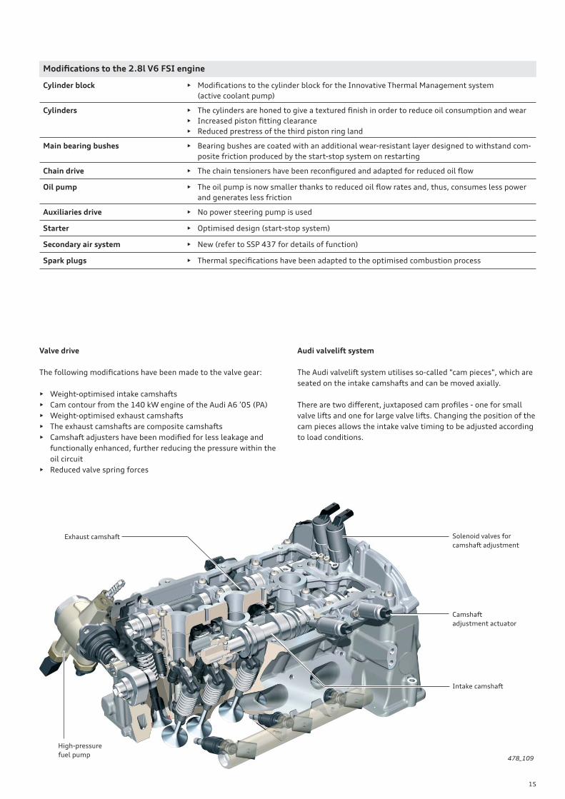
Valve drive
The following modifi cations have been made to the valve gear:
• Weight-optimised intake camshafts
• Cam contour from the 140 kW engine of the Audi A6 ’05 (PA)
• Weight-optimised exhaust camshafts
• The exhaust camshafts are composite camshafts
• Camshaft adjusters have been modifi ed for less leakage and
functionally enhanced, further reducing the pressure within the
oil circuit
• Reduced valve spring forces
Audi valvelift system
The Audi valvelift system utilises so-called "cam pieces", which are
seated on the intake camshafts and can be moved axially.
There are two diff erent, juxtaposed cam profi les - one for small
valve lifts and one for large valve lifts. Changing the position of the
cam pieces allows the intake valve timing to be adjusted according
to load conditions.
Intake camshaft
Solenoid valves for
camshaft adjustment
Camshaft
adjustment actuator
Exhaust camshaft
High-pressure
fuel pump

16
Reference
For further information about the design and functionality of the 3.0l V6 TFSI engine, please refer to Self-Study Programme
437 "Audi 3.0l V6 TFSI Engine with Roots Blower".
3.0l V6 TFSI engine
Technical features
Oil pump with reduced power consumption
Friction-reduced chain gear with:
− Modifi ed camshafts
− Leakage-reduced camshaft adjusters
New spark plugs
17
478_009
Start-stop system and brake energy recuperation
Innovative Thermal Management system with active coolant pump
Improved high-pressure injectors
Adapted belt drive
(without power steering pump)

18
478_053
Specifi cations
Torque-power curve
Power in kW
Torque in Nm
Engine code CGWB
Type Six cylinder V engine with 90° V angle
Displacement in cm3 2995
Power output in kW (HP) 220 (300) at 5250 – 6500
Torque in Nm 440 at 2900 – 4500
Number of valves per cylinder 4
Bore in mm 84.5
Stroke in mm 89
Compression ratio 10.5 : 1
Powertrain type quattro
Engine management Simos 8
Fuel Premium unleaded (sulphur-free) 95 RON
Emissions standard EU V
CO2 emission in g/km 190
Engine speed [rpm]

19
Modifi cations to the 3.0l V6 TFSI engine
Cylinder block • Modifi cations to the cylinder block for the Innovative Thermal Management system
(active coolant pump)
Cylinders • The cylinders are honed to give a textured fi nish in order to reduce oil consumption and wear
• Increased piston fi tting clearance
• Reduced prestress of the third piston ring land
Main bearing bushes • Bearing bushes are coated with an additional wear-resistant layer designed to withstand com-
posite friction produced by the start-stop system on restarting
Chain drive • The chain tensioners have been reconfi gured and adapted for reduced oil fl ow
Camshafts • Weight-optimised intake camshafts
• Cam contour from the 140 kW engine of the Audi A6 ’05 (PA)
• Weight-optimised exhaust camshafts
• All camshafts are composite camshafts
Camshaft adjuster • Modifi ed for less leakage and functionally enhanced, further reducing the pressure within the
oil circuit
Valve drive • Reduced spring forces
Oil pump • The oil pump is now smaller thanks to reduced oil fl ow rates and, thus, consumes less power
and generates less friction
Auxiliaries drive • No power steering pump is used
Starter • Optimised design (start-stop system)
Spark plugs • Thermal specifi cations have been adapted to the optimised combustion process
478_110
Charging
The 3.0l V6 TFSI is currently the top-of-the-range Audi V6 petrol
engine.
• Fast dynamic torque build-up
• Flat torque curve
• Excellent drive-away performance
• Maintenance-free operation
A special feature of this engine is that it is charged by a Roots
blower which off ers a string of advantages:
• Harmonised basic engineering concept for naturally aspirated
engine and supercharged engine
• Highly compact supercharger unit design
• High percentage of common parts shared with other V engined
models
Supercharger module
Rotors
Bypass fl ap
Main throttle fl ap
Input gear
Charge air cooler

20
Reference
For further information about the design and functionality of the 3.0l V6 TDI engine, please refer to Self-Study Programme
479 "Audi 3.0l V6 TDI Engine (second generation)".
3.0l V6 TDI engine (2nd generation)
Technical features
Intake manifold with a single swirl fl ap
Common rail injection system
Chain drive
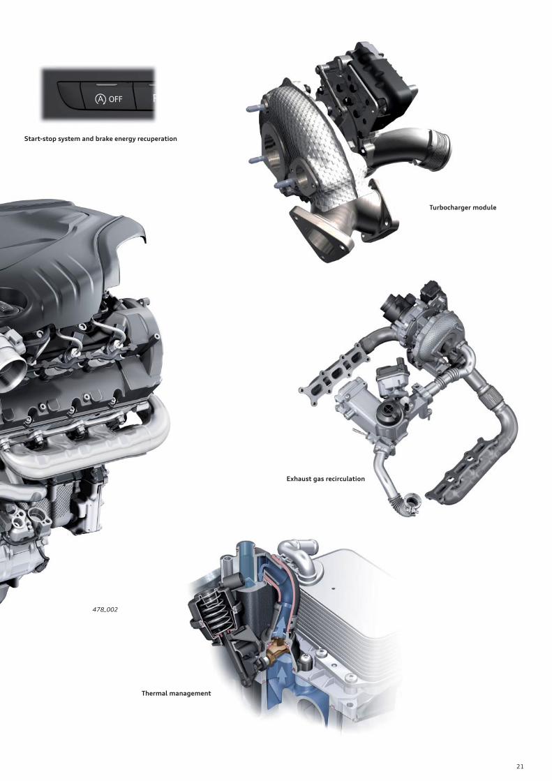
21
478_002
Turbocharger module
Exhaust gas recirculation
Thermal management
Start-stop system and brake energy recuperation
22
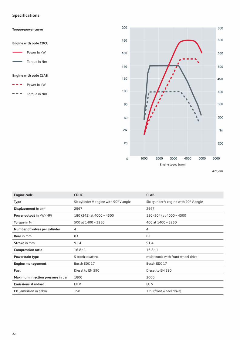
Specifi cations
Torque-power curve
Engine with code CDCU
Power in kW
Torque in Nm
Engine with code CLAB
Power in kW
Torque in Nm
478_001
Engine code CDUC CLAB
Type Six cylinder V engine with 90° V angle Six cylinder V engine with 90° V angle
Displacement in cm3 2967 2967
Power output in kW (HP) 180 (245) at 4000 – 4500 150 (204) at 4000 – 4500
Torque in Nm 500 at 1400 – 3250 400 at 1400 – 3250
Number of valves per cylinder 4 4
Bore in mm 83 83
Stroke in mm 91.4 91.4
Compression ratio 16.8 : 1 16.8 : 1
Powertrain type S tronic quattro multitronic with front wheel drive
Engine management Bosch EDC 17 Bosch EDC 17
Fuel Diesel to EN 590 Diesel to EN 590
Maximum injection pressure in bar 1800 2000
Emissions standard EU V EU V
CO2 emission in g/km 158 139 (front wheel drive)
Engine speed [rpm]

23
In addition to the performance versions, the new generation of
engines includes an effi ciency version developing 150 kW and
400 Nm (engine code CLAB).
Diff erences between the effi ciency and performance versions are:
• An exhaust turbocharger GT2056 optimised for lower power
output
• Common rail injection system with a maximum rail pressure of
2000 bar
• Reduced hydraulic fl ow through the eight-hole nozzles in the
piezoelectric injector
Modifi cations to the 3.0l V6 TDI engine
Engine mechanicals • Crank mechanism
• With weight-reduced bores in the crank pins
• Chain drive reduced from four to two simplex chains
• Intake ports with cylinder heads optimised for swirl and fl ow
• Layout and downsizing of the exhaust valves
• Lighter composite camshafts with new mounting
• Further improved engine ventilation system
Oil circuit • Oil circuit with dual-stage fl ow controlled vane cell pump
• Oil cooler bypass thermostat
Cooling system • Revised cooling system (cylinder head and cylinder block cooling circuit)
• Flow optimisation
• Innovative Thermal Management
Exhaust gas recirculation • Optimised and compactly built in modular design (EGR valve, EGR cooler and bypass valve in
module)
• Active EGR cooler without thermostat control and auxiliary coolant pump
Charging • Exhaust gas turbocharger modifi ed for reduced internal friction losses
• Diff erent chargers are used depending on engine power output
• Overboost function
Air fl ow • Dual-fl ow superposed intake manifold with only one central swirl fl ap in lieu of the previous
six swirl fl aps
Common rail injection system • Injection system with injection pressures of up to 2000 bar
• Dual-piston high pressure pump (CP4.2)
• High pressure fuel pump driven by auxiliaries chain
Exhaust gas aftertreatment • Use of aluminium titanate as a new diesel particulate fi lter substrate
• More advanced generation of particulate fi lters (three post injections)
Auxiliaries drive • No power steering pump is used
A further measure to increase the effi ciency of the 150 kW unit is
a performance-based adjustment in the exhaust timing from
202 deg. to 176 deg., thus allowing more effi cient use to be made
of expansion work in the cylinder. Thus, fuel consumption has been
reduced still further.
Engine version developing 150 kW (effi ciency version)
24
Innovative Thermal Management (ITM)
ITM is a subsystem of the engine control unit. The subsystems
indicate their "status" to the ITM (e.g. heating required, no heating
required, etc.).
The ITM function weighs up requirements and decides which users
have the highest priority and, thus, determines which actuators
need to be activated. ITM sends activation commands to the users,
which in turn activate the actuators.
Units are warmed up in two phases:
• Phase 1: the stationary coolant produces a more rapid increase
in temperature within the engine, thereby reducing friction
losses. The injection cycle can also be optimised.
• Phase 2: the hot coolant is now used to rapidly heat the gear oil
via an heat exchanger. For this purpose, the heat fl ow is
diverted by an electrical control valve actuated by the gearbox
control unit.
The mixing phase is cycled to avoid excessive thermal stresses
and ensure that the hot engine coolant is not circulated imme-
diately (this would impair the frictional properties of the
engine).
Heating of the cabin
If the customer wants the cabin to be heated as quickly as pos-
sible, heat is transferred as quickly as possible in order to heat the
cabin. In this case, the engine coolant is not stationary.
Gear oil cooling/heating
However, the gear oil is not only heated. It can also be cooled, as
required. Since there is no separate cooling circuit, the gear oil is
cooled down to the temperature level of the engine cooling circuit.
The coolant fl ow to the gear oil cooler is shut off by the coolant
fl ow control valve during the optimal gearbox temperature phase.
Technical summary of the Innovative Thermal Management system
2.8l V6 FSI engine 3.0l V6 TFSI engine 3.0l V6 TDI engine
• Active coolant pump • Active coolant pump • Coolant shut-off valve
• Ball valve in small coolant circuit
(actuated by N489)
• Cylinder head coolant valve
(same as on 4.2l V8 FSI of A8 ’10)
• Two sensors:
• Temperature sender for engine tem-
perature control G694
• Coolant temperature sender G62
• Two sensors:
• Temperature sender for engine tem-
perature control G694
• Coolant temperature sender G62
• Two sensors:
• Temperature sender for engine tem-
perature control G694
• Coolant temperature sender G62
• Gear oil heating/cooling • Gear oil heating/cooling • Gear oil heating/cooling
• Heating cut-off • Heating cut-off • Heating cut-off
• Thermostat opens at 95 °C • Thermostat opens at 87 °C • Mapped engine cooling thermostat
(65 °C – 90 °C)
• Oil cooler bypass thermostat

25
An engine temperature sensor is used on petrol models. A special
feature of this type of sensor is that it has a larger surface area due
to its thread being in the heat transfer zone (allowing faster
heating and cooling). The temperature sender G694 is mounted in
the cylinder head, i.e. in a position where components can be
expected to reach critical temperatures most quickly.
The technical reason for the use of temperature sender G694 is to
provide component protection. It ensures that coolant pump drive
is maintained even even in the event of a torn ribbed V-belt and
sudden or gradual coolant loss - situations in which a conventional
coolant sensor would be left "high and dry" and unable to deliver
any information on engine oil temperature.
The new sensor also protects against "coolant boil-off " since it
enables warnings to be issued earlier by providing a "faster"
measurement at the "critical point".
The Innovative Thermal Management control unit performs the
following functions:
• Warm-up control when the coolant is stationary
• Actuator control (e.g. active coolant pump)
• Heater coolant
• Coolant radiator fan
• Coolant protection against boiling
Sensor housing
Contacts
Resistance
Moulding compound
Heat conducting paste
Temperature sensor
(NTC)
Sensor tip478_057
Temperature sender for engine temperature control G694
Active coolant pump
The coolant pump is activated via the engine control unit, which
does so by switching the vacuum on and off using a solenoid valve.
Activating the coolant pump stops the coolant fl ow since the pilot
valve is inverted over the pump gear. Thus, the fl ow of coolant
through the engine is shut off completely. In this operating state,
drive power is reduced.
Brief activation of the coolant pump at high engine speeds serves
to protect the engine from overheating. The coolant fl ow is acti-
vated in a cycled fashion. This allows the engine temperature to be
gradually equalised during the mixing phase after the warm-up
phase.
Function
Evacuating the vacuum chamber exerts force on the pilot valve
piston. Thus, the pilot valve is pushed over the impeller on the
cylinder block against the pressure of the spring via the guide rods.
The coolant fl ow is hereby restricted at the pump outlet on the
pressure side. Three circumferential return springs ensure that full
delivery is maintained in the event of problems with the vacuum
supply.
The pump is not activated at coolant temperatures below –20 °C
because the seals and diaphragms could otherwise suff er damage.
The pump is not activated on restarting the engine either.
478_085
478_088
Pilot valve piston
Slide control valveGuide rods
Resetting spring
26
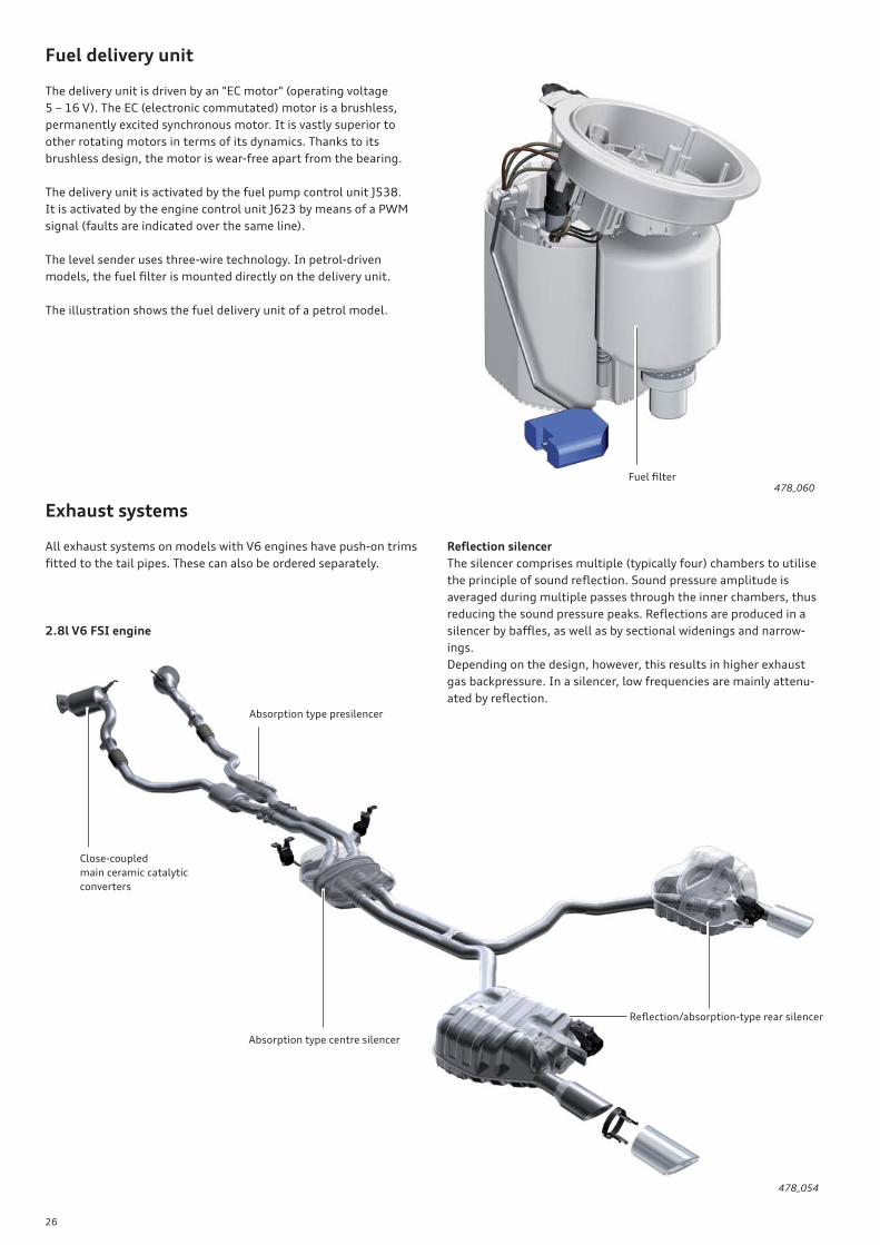
Exhaust systems
All exhaust systems on models with V6 engines have push-on trims
fi tted to the tail pipes. These can also be ordered separately.
Fuel delivery unit
The delivery unit is driven by an "EC motor" (operating voltage
5 – 16 V). The EC (electronic commutated) motor is a brushless,
permanently excited synchronous motor. It is vastly superior to
other rotating motors in terms of its dynamics. Thanks to its
brushless design, the motor is wear-free apart from the bearing.
The delivery unit is activated by the fuel pump control unit J538.
It is activated by the engine control unit J623 by means of a PWM
signal (faults are indicated over the same line).
The level sender uses three-wire technology. In petrol-driven
models, the fuel fi lter is mounted directly on the delivery unit.
The illustration shows the fuel delivery unit of a petrol model.
478_060
478_054
2.8l V6 FSI engine
Refl ection silencer
The silencer comprises multiple (typically four) chambers to utilise
the principle of sound refl ection. Sound pressure amplitude is
averaged during multiple passes through the inner chambers, thus
reducing the sound pressure peaks. Refl ections are produced in a
silencer by baffl es, as well as by sectional widenings and narrow-
ings.
Depending on the design, however, this results in higher exhaust
gas backpressure. In a silencer, low frequencies are mainly attenu-
ated by refl ection.
Close-coupled
main ceramic catalytic
converters
Absorption type presilencer
Absorption type centre silencer
Refl ection/absorption-type rear silencer
Fuel fi lter
27
478_055
478_056
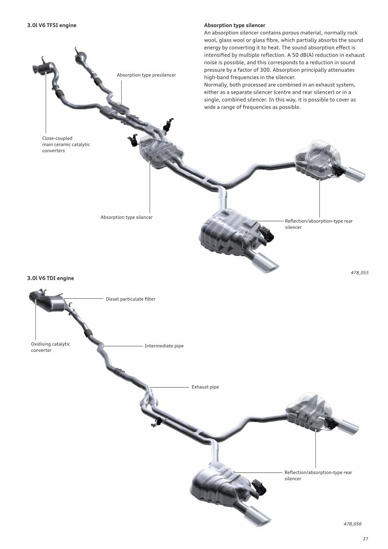
3.0l V6 TFSI engine
3.0l V6 TDI engine
Absorption type silencer
An absorption silencer contains porous material, normally rock
wool, glass wool or glass fi bre, which partially absorbs the sound
energy by converting it to heat. The sound absorption eff ect is
intensifi ed by multiple refl ection. A 50 dB(A) reduction in exhaust
noise is possible, and this corresponds to a reduction in sound
pressure by a factor of 300. Absorption principally attenuates
high-band frequencies in the silencer.
Normally, both processed are combined in an exhaust system,
either as a separate silencer (centre and rear silencer) or in a
single, combined silencer. In this way, it is possible to cover as
wide a range of frequencies as possible.
Close-coupled
main ceramic catalytic
converters
Absorption type presilencer
Absorption type silencerRefl ection/absorption-type rear
silencer
Refl ection/absorption-type rear
silencer
Oxidising catalytic
converter
Diesel particulate fi lter
Intermediate pipe
Exhaust pipe
28
Reference
The drive concept of the Audi A7 Sportback is in many respect identical to that of the B8 series (Audi A4/A5). For information
about the axle position and the new sealing and assembly concept of the axle fl ange for the rear axle diff erential, please
refer to SSPs 392 and 409 as well as Audi iTV programme – Audi A5 Power Transmission – (broadcast on 02.2010). This
information also applies to the Audi A7 Sportback and represents basic knowledge of this topic.
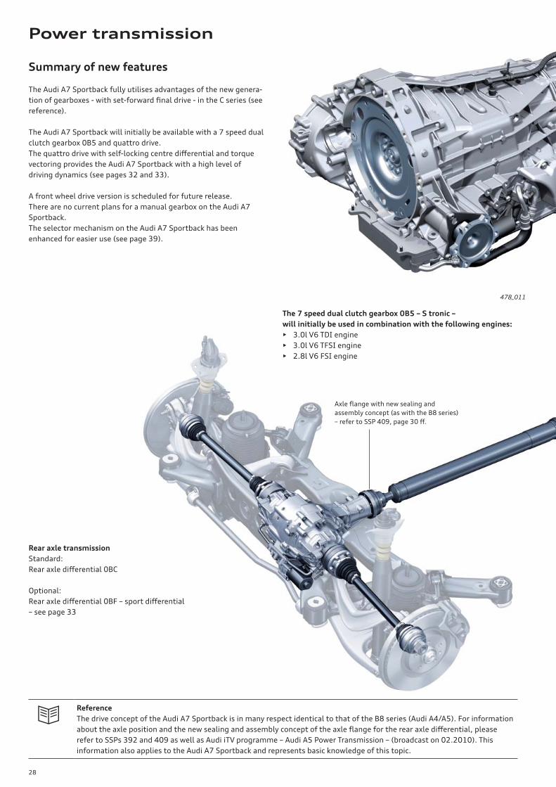
Summary of new features
The Audi A7 Sportback fully utilises advantages of the new genera-
tion of gearboxes - with set-forward fi nal drive - in the C series (see
reference).
The Audi A7 Sportback will initially be available with a 7 speed dual
clutch gearbox 0B5 and quattro drive.
The quattro drive with self-locking centre diff erential and torque
vectoring provides the Audi A7 Sportback with a high level of
driving dynamics (see pages 32 and 33).
A front wheel drive version is scheduled for future release.
There are no current plans for a manual gearbox on the Audi A7
Sportback.
The selector mechanism on the Audi A7 Sportback has been
enhanced for easier use (see page 39).
478_011
Rear axle transmission
Standard:
Rear axle diff erential 0BC
Optional:
Rear axle diff erential 0BF – sport diff erential
– see page 33
Axle fl ange with new sealing and
assembly concept (as with the B8 series)
– refer to SSP 409, page 30 ff .
The 7 speed dual clutch gearbox 0B5 – S tronic –
will initially be used in combination with the following engines:
• 3.0l V6 TDI engine
• 3.0l V6 TFSI engine
• 2.8l V6 FSI engine
Power transmission
29
478_010
478_027 478_018
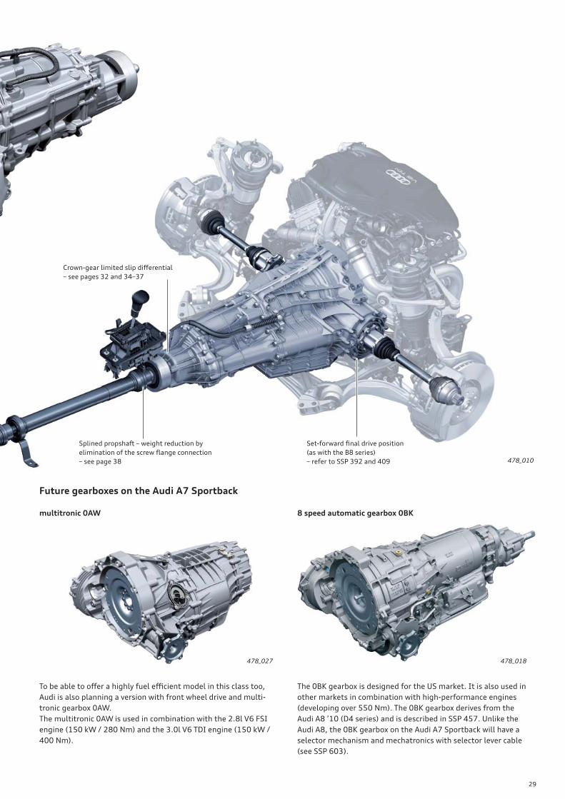
Splined propshaft – weight reduction by
elimination of the screw fl ange connection
– see page 38
Set-forward fi nal drive position
(as with the B8 series)
– refer to SSP 392 and 409
Crown-gear limited slip diff erential
– see pages 32 and 34–37
Future gearboxes on the Audi A7 Sportback
multitronic 0AW 8 speed automatic gearbox 0BK
To be able to off er a highly fuel effi cient model in this class too,
Audi is also planning a version with front wheel drive and multi-
tronic gearbox 0AW.
The multitronic 0AW is used in combination with the 2.8l V6 FSI
engine (150 kW / 280 Nm) and the 3.0l V6 TDI engine (150 kW /
400 Nm).
The 0BK gearbox is designed for the US market. It is also used in
other markets in combination with high-performance engines
(developing over 550 Nm). The 0BK gearbox derives from the
Audi A8 ’10 (D4 series) and is described in SSP 457. Unlike the
Audi A8, the 0BK gearbox on the Audi A7 Sportback will have a
selector mechanism and mechatronics with selector lever cable
(see SSP 603).
30
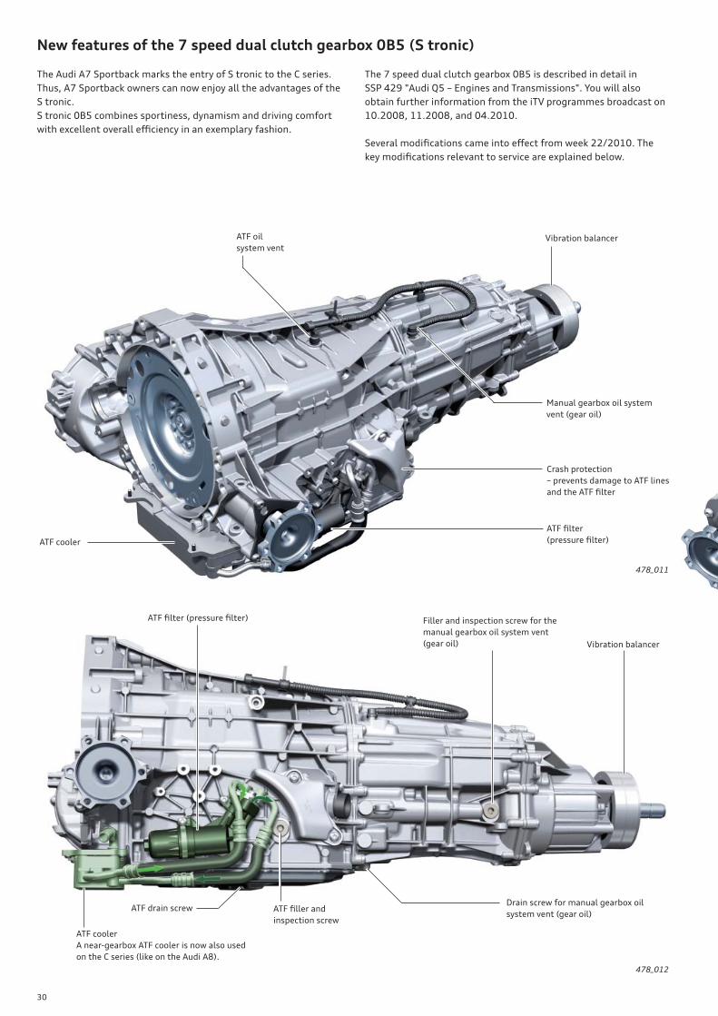
New features of the 7 speed dual clutch gearbox 0B5 (S tronic)
The Audi A7 Sportback marks the entry of S tronic to the C series.
Thus, A7 Sportback owners can now enjoy all the advantages of the
S tronic.
S tronic 0B5 combines sportiness, dynamism and driving comfort
with excellent overall effi ciency in an exemplary fashion.
The 7 speed dual clutch gearbox 0B5 is described in detail in
SSP 429 "Audi Q5 – Engines and Transmissions". You will also
obtain further information from the iTV programmes broadcast on
10.2008, 11.2008, and 04.2010.
Several modifi cations came into eff ect from week 22/2010. The
key modifi cations relevant to service are explained below.
ATF oil
system ventVibration balancer
ATF cooler
Manual gearbox oil system
vent (gear oil)
Crash protection
– prevents damage to ATF lines
and the ATF fi lter
ATF fi lter
(pressure fi lter)
ATF cooler
A near-gearbox ATF cooler is now also used
on the C series (like on the Audi A8).
Vibration balancer
Filler and inspection screw for the
manual gearbox oil system vent
(gear oil)
Drain screw for manual gearbox oil
system vent (gear oil)ATF drain screw ATF fi ller and
inspection screw
478_011
478_012
ATF fi lter (pressure fi lter)

31
Vibration absorber1)
Depending on which engine is combined with the 0B5 gearbox,
diff erent vibration absorbers are used:
the fl exural vibration absorber – is bolted to the gearbox cover and
eliminates fl exural vibration
the torsional vibration absorber – is press-fi tted to the gearbox
output shaft and eliminates torsional vibration
the combination absorber – is, like the torsional vibration absorber,
press-fi tted to the gearbox output shaft and eliminates fl exural
and torsional vibration
ATF fi lter (pressure fi lter)
The 0B5 gearbox on models manufactured after 22/1010 has a
new ATF fi lter. The new ATF fi lter is integrated in the ATF line
fi tting and includes a fi lter cartridge. The fi lter cartridge also has
to be replaced when changing the ATF.
Rubber element
Absorber mass
Combination absorber – externally, it is very diffi cult to
distinguish between this absorber and the torsional vibra-
tion absorber. For identifi cation purposes, therefore, the
combination absorber has a circumferential groove
1) There are also versions in which no vibration absorber is installed.
Pay attention to the correct assignments of the various absorbers
in ETKA (electronic parts catalogue).
ATF pipe
Filter cartridge
Connections for
ATF lines
478_014
478_013

32
The quattro drive with self-locking centre diff erential and torque
vectoring provides the Audi A7 Sportback with a high level of
driving dynamics.
Power is distributed to the front and rear axles by the proven
self-locking centre diff erential with asymmetric-dynamic torque
split as seen in the B series.
A signifi cant reduction in driveline weight was achieved, among
other things, by compactly designing the centre diff erential and by
using a spline to couple the gearbox output shaft to the prop shaft
(see page 38).
quattro powertrain on the Audi A7 Sportback
Audi recently began coupling the self-locking centre diff erential to
a torque vectoring system. This software, specially developed by
Audi, is integrated in the ESP control unit.
The defi niton of "driving" is diff erent to everyone. In addition to a
range of other optional dynamics-enhancing systems, the sport
diff erential is strongly recommended for anyone seeking to experi-
ence the true driving dynamics of the Audi A7 Sportback.
478_015
approx. 30 %
approx. 20 %
approx. 20 %
approx. 30 %
The illustration shows the Audi A6 ’11.
Self-locking centre diff erential with
asymmetrical-dynamic torque split
Gearbox output shaft –
transmits torque to the prop shaft
Shaft with spur gear – transmits torque
to the front axle drive via the sideshaft
Gearbox output shaft (output shaft
from manual gearbox – transmits
torque to the centre diff erential)
33
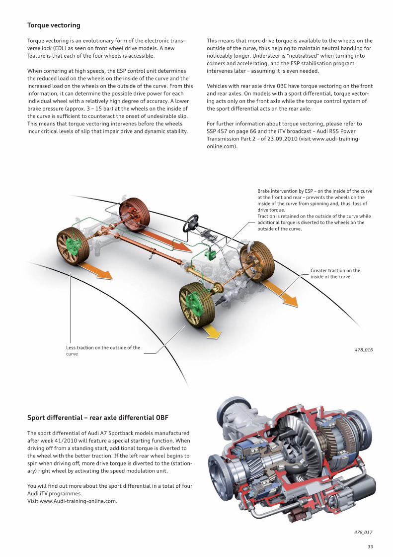
Torque vectoring
Torque vectoring is an evolutionary form of the electronic trans-
verse lock (EDL) as seen on front wheel drive models. A new
feature is that each of the four wheels is accessible.
When cornering at high speeds, the ESP control unit determines
the reduced load on the wheels on the inside of the curve and the
increased load on the wheels on the outside of the curve. From this
information, it can determine the possible drive power for each
individual wheel with a relatively high degree of accuracy. A lower
brake pressure (approx. 3 – 15 bar) at the wheels on the inside of
the curve is suffi cient to counteract the onset of undesirable slip.
This means that torque vectoring intervenes before the wheels
incur critical levels of slip that impair drive and dynamic stability.
This means that more drive torque is available to the wheels on the
outside of the curve, thus helping to maintain neutral handling for
noticeably longer. Understeer is "neutralised" when turning into
corners and accelerating, and the ESP stabilisation program
intervenes later – assuming it is even needed.
Vehicles with rear axle drive 0BC have torque vectoring on the front
and rear axles. On models with a sport diff erential, torque vector-
ing acts only on the front axle while the torque control system of
the sport diff erential acts on the rear axle.
For further information about torque vectoring, please refer to
SSP 457 on page 66 and the iTV broadcast – Audi RS5 Power
Transmission Part 2 – of 23.09.2010 (visit www.audi-training-
online.com).
Sport diff erential – rear axle diff erential 0BF
The sport diff erential of Audi A7 Sportback models manufactured
after week 41/2010 will feature a special starting function. When
driving off from a standing start, additional torque is diverted to
the wheel with the better traction. If the left rear wheel begins to
spin when driving off , more drive torque is diverted to the (station-
ary) right wheel by activating the speed modulation unit.
You will fi nd out more about the sport diff erential in a total of four
Audi iTV programmes.
Visit www.Audi-training-online.com.
478_016
478_017
Brake intervention by ESP – on the inside of the curve
at the front and rear – prevents the wheels on the
inside of the curve from spinning and, thus, loss of
drive torque.
Traction is retained on the outside of the curve while
additional torque is diverted to the wheels on the
outside of the curve.
Greater traction on the
inside of the curve
Less traction on the outside of the
curve

34
Self-locking centre diff erential with asymmetrical-dynamic torque split
The gearbox output torque is input into the diff erential housing
and transmitted to the diff erential gears. Two diff erential gears are
in mesh - a short gear and a long gear. The short diff erential gears
transmit torque to the front axle sun gear, while the long diff eren-
tial gears transmit torque to the rear axle sun gear.
Background
To be able to understand force distribution in the self-locking
centre diff erential, one has to look at two eff ects – basic torque
split and dynamic torque split. When driving, the dynamic torque
split is always superimposed on the basic torque split. In this
context, the appendage "asymmetric" means that there are diff er-
ing degrees of torque split between the front and rear axles.
An asymmetric self-locking centre diff erential is defi ned by four
operating states:
• Distribution to the front axle under throttle
• Distribution to the front axle during overrun
• Distribution to the rear axle under throttle
• Distribution to the rear axle during overrun
The diff erential has a diff erent lock-up eff ect in each of these four
operating states. The torque split in the above four operating
states is defi ned at the design stage in order to provide the desired
handling under throttle and during overrun.
1) The term "reference diameter" is used to describe the eff ective
working diameter of a gear.
Shaft with spur gear – transmits torque
to the front axle drive via the sideshaft
Friction plates
Gearbox output shaft –
transmits torque to the prop shaft
Sun gear,
front axle drive
Diff erential gear,
short
Diff erential gear,
long
Sun gear, rear axle drive478_019
Design and operation
The key components are the two sun gears (also referred to as
worm gears), the corresponding diff erential gears (also referred to
as planetary gears or worm gears), as well as the diff erential case.
The diff erential gears are mounted in bearings in the diff erential
case and therefore do not require any axles.
The sun gears and the diff erential gears mesh with one another via
special helical gearing, thereby producing axial force.
The sun gears are axially supported by special friction plates which
are a key factor contributing to the lock-up eff ect of the diff eren-
tial.
Both sun gears have diff erent pitch circle diameters1). This results
in an asymmetric basic torque split. A locking torque proportional
to the drive torque, the so-called dynamic torque split, is produced
in the diff erential. The asymmetric basic torque split and the
dynamic torque split dictate the amount of torque that can be
transmitted to each axle.
Depending on the traction conditions, up to approx. 70 % of drive
torque can be directed to the front axle or approx. 80 % to the rear
axle, without the need for corrective intervention by ESP.
35
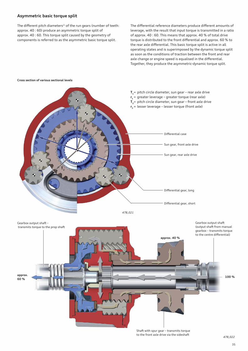
The diff erent pitch diameters1) of the run gears (number of teeth:
approx. 40 : 60) produce an asymmetric torque split of
approx. 40 : 60. This torque split caused by the geometry of
components is referred to as the asymmetric basic torque split.
Asymmetric basic torque split
The diff erential reference diameters produce diff erent amounts of
leverage, with the result that input torque is transmitted in a ratio
of approx. 40 : 60. This means that approx. 40 % of total drive
torque is distributed to the front diff erential and approx. 60 % to
the rear axle diff erential. This basic torque split is active in all
operating states and is superimposed by the dynamic torque split
as soon as the conditions of traction between the front and rear
axle change or engine speed is equalised in the diff erential.
Together, they produce the asymmetric-dynamic torque split.
T1 = pitch circle diameter, sun gear – rear axle drive
r1
= greater leverage – greater torque (rear axle)
T2 = pitch circle diameter, sun gear – front axle drive
r2
= lesser leverage – lesser torque (front axle)
Cross section of various sectional levels
Diff erential case
Sun gear, front axle drive
Sun gear, rear axle drive
Diff erential gear, long
Diff erential gear, short
approx.
60 %
r1
T1
r2
T2
approx. 40 %
100 %
Gearbox output shaft
(output shaft from manual
gearbox – transmits torque
to the centre diff erential)
Shaft with spur gear – transmits torque
to the front axle drive via the sideshaft
Gearbox output shaft –
transmits torque to the prop shaft
478_021
478_022

36
Friction plate under throttle
Friction plate in overrun
Axial forces
478_023
Friction plate under throttle
In addition to the asymmetric basic torque split of approx. 40 : 60,
a locking torque proportional to the drive torque is produced in the
diff erential. This locking torque plus basic torque split give the
possible torque distribution to both axles.
Thus, the diff erential locks up before any changes in traction take
eff ect between the axles. If an axle loses traction, drive torque is
immediately diverted to the other axle within the allowable
lock-up range and according to how much traction the wheels have.
If the working range is exceeded, corrective intervention by the
ESP delivers additional torque and so provides forward drive.
Torque split up to 20 : 80
If the front axle loses traction – without yet exceeding the traction
limit – the rear axle can transmit up to 80 % of drive torque. If the
traction limit is exceeded, a corresponding amount of slip will
occur at the wheels on the rear axle.
Longitudinal section of various cutting planes
If wheel slip exceeds a defi ned level, the ESP control system
intervenes producing additional torque. The additional torque, the
basic torque split and the lock-up eff ect produce a corresponding
drive torque at the rear axle.
Asymmetric-dynamic torque split
Function
The diff erential gears and the sun gears have special helical
gearing. The drive torque produces a corresponding axial force as
well as a certain amount of frictional force in the gearing and on
the contact faces of the gears.
The suns gears are supported by the diff erential case. So-called
friction plates which are used to produce frictional torque are
located between the sun gears and the diff erential case. The
frictional force in the gearing and the frictional torque acting on
the friction plates give the diff erential its desired lock-up eff ect.
The lock-up eff ect is defi ned by the lock-up value. The lock-up value
describes the relationship between output torque at both diff eren-
tial outputs as a result of the lock-up eff ect of the diff erential.
up to 80 %
up to 20 %
100 %
Reference
You will fi nd further general information in Self Study Programme 363 "Audi Q7 – Transmission / Distributor Gear",
page 18 ff .
37
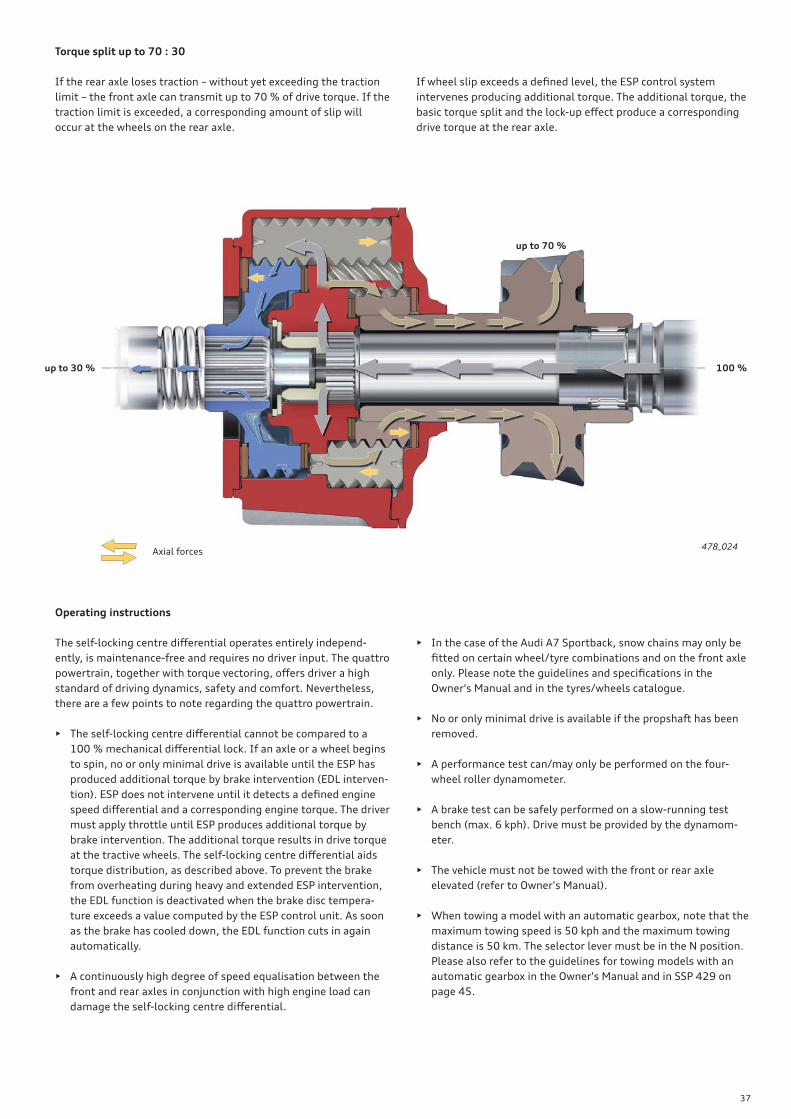
478_024
Torque split up to 70 : 30
If the rear axle loses traction – without yet exceeding the traction
limit – the front axle can transmit up to 70 % of drive torque. If the
traction limit is exceeded, a corresponding amount of slip will
occur at the wheels on the rear axle.
If wheel slip exceeds a defi ned level, the ESP control system
intervenes producing additional torque. The additional torque, the
basic torque split and the lock-up eff ect produce a corresponding
drive torque at the rear axle.
up to 30 %
up to 70 %
100 %
Axial forces
Operating instructions
The self-locking centre diff erential operates entirely independ-
ently, is maintenance-free and requires no driver input. The quattro
powertrain, together with torque vectoring, off ers driver a high
standard of driving dynamics, safety and comfort. Nevertheless,
there are a few points to note regarding the quattro powertrain.
• The self-locking centre diff erential cannot be compared to a
100 % mechanical diff erential lock. If an axle or a wheel begins
to spin, no or only minimal drive is available until the ESP has
produced additional torque by brake intervention (EDL interven-
tion). ESP does not intervene until it detects a defi ned engine
speed diff erential and a corresponding engine torque. The driver
must apply throttle until ESP produces additional torque by
brake intervention. The additional torque results in drive torque
at the tractive wheels. The self-locking centre diff erential aids
torque distribution, as described above. To prevent the brake
from overheating during heavy and extended ESP intervention,
the EDL function is deactivated when the brake disc tempera-
ture exceeds a value computed by the ESP control unit. As soon
as the brake has cooled down, the EDL function cuts in again
automatically.
• A continuously high degree of speed equalisation between the
front and rear axles in conjunction with high engine load can
damage the self-locking centre diff erential.
• In the case of the Audi A7 Sportback, snow chains may only be
fi tted on certain wheel/tyre combinations and on the front axle
only. Please note the guidelines and specifi cations in the
Owner's Manual and in the tyres/wheels catalogue.
• No or only minimal drive is available if the propshaft has been
removed.
• A performance test can/may only be performed on the four-
wheel roller dynamometer.
• A brake test can be safely performed on a slow-running test
bench (max. 6 kph). Drive must be provided by the dynamom-
eter.
• The vehicle must not be towed with the front or rear axle
elevated (refer to Owner's Manual).
• When towing a model with an automatic gearbox, note that the
maximum towing speed is 50 kph and the maximum towing
distance is 50 km. The selector lever must be in the N position.
Please also refer to the guidelines for towing models with an
automatic gearbox in the Owner's Manual and in SSP 429 on
page 45.
38
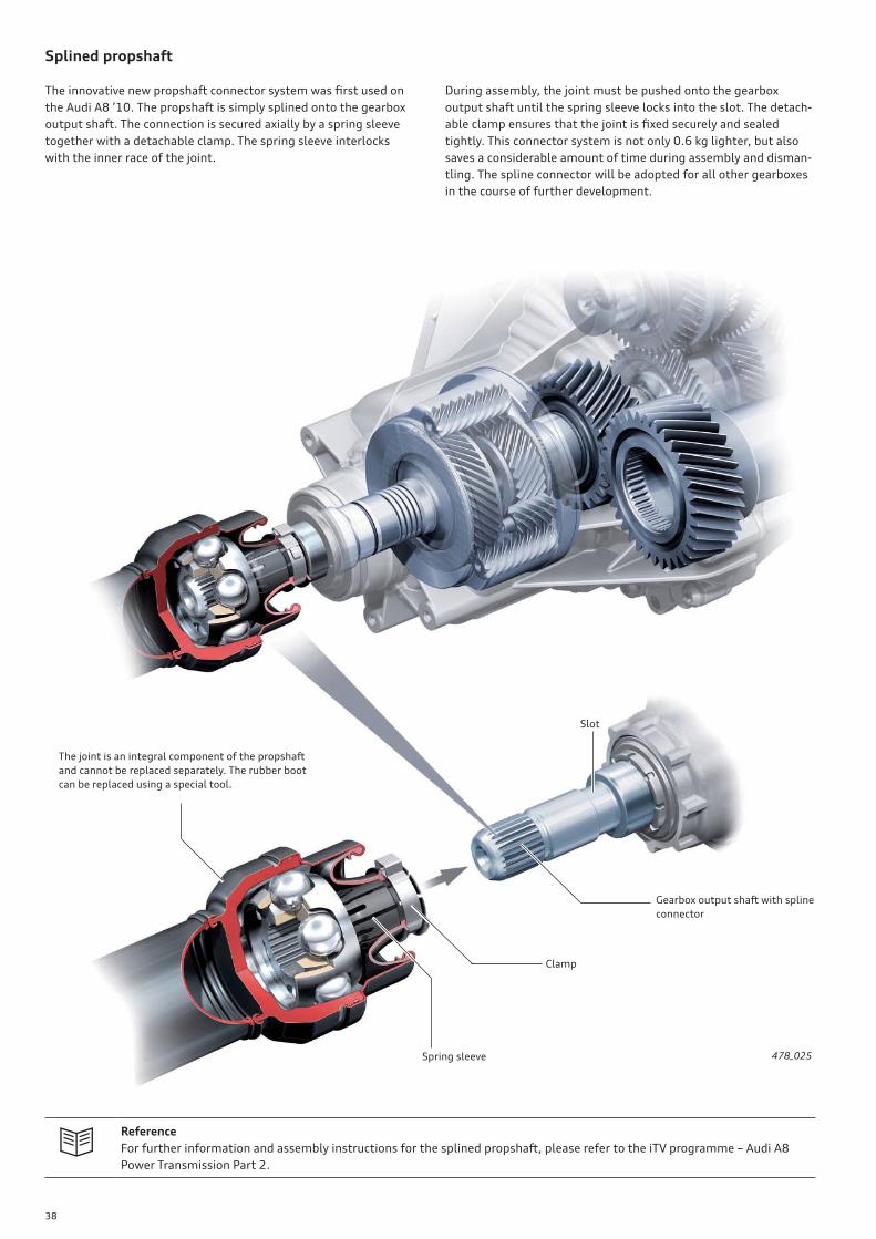
Splined propshaft
The innovative new propshaft connector system was fi rst used on
the Audi A8 ’10. The propshaft is simply splined onto the gearbox
output shaft. The connection is secured axially by a spring sleeve
together with a detachable clamp. The spring sleeve interlocks
with the inner race of the joint.
During assembly, the joint must be pushed onto the gearbox
output shaft until the spring sleeve locks into the slot. The detach-
able clamp ensures that the joint is fi xed securely and sealed
tightly. This connector system is not only 0.6 kg lighter, but also
saves a considerable amount of time during assembly and disman-
tling. The spline connector will be adopted for all other gearboxes
in the course of further development.
478_025
The joint is an integral component of the propshaft
and cannot be replaced separately. The rubber boot
can be replaced using a special tool.
Spring sleeve
Clamp
Gearbox output shaft with spline
connector
Slot
Reference
For further information and assembly instructions for the splined propshaft, please refer to the iTV programme – Audi A8
Power Transmission Part 2.

39
Shift Control
The operating logic of the selector for the sport program (speed S)
has been reconfi gured. To shift from D to S (or from S to D), the
selector is fl icked back out of D once only. The selector always
springs back to the D/S position. The shift schematic has has been
adapted to the new operating logic.
Advantages for the customer:
• on models equipped with Audi drive select, the S program can
now be selected irrespective of the mode selected in Audi drive
select.
• tiptronic mode can now also be selected in the S program
Reference
For further information about the selector mechanism, please refer to Self Study Programme 409 "Audi A4 ’08", page 34 ff .
The shift schematic with gearshift indicator is inte-
grated in the console trim frame. The display unit Y26
is installed from below as a separate component.478_026
40
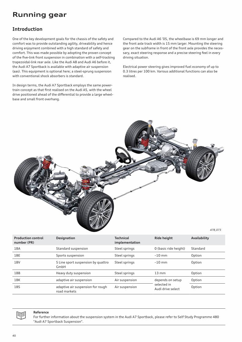
Introduction
One of the key development goals for the chassis of the safety and
comfort was to provide outstanding agility, driveability and hence
driving enjoyment combined with a high standard of safety and
comfort. This was made possible by adopting the proven concept
of the fi ve-link front suspension in combination with a self-tracking
trapezoidal-link rear axle. Like the Audi A8 and Audi A6 before it,
the Audi A7 Sportback is available with adaptive air suspension
(aas). This equipment is optional here; a steel-sprung suspension
with conventional shock absorbers is standard.
In design terms, the Audi A7 Sportback employs the same power-
train concept as that fi rst realised on the Audi A5, with the wheel
drive positioned ahead of the diff erential to provide a large wheel-
base and small front overhang.
Compared to the Audi A6 ’05, the wheelbase is 69 mm longer and
the front axle track width is 15 mm larger. Mounting the steering
gear on the subframe in front of the front axle provides the neces-
sary, exact steering response and a precise steering feel in every
driving situation.
Electrical power steering gives improved fuel economy of up to
0.3 litres per 100 km. Various additional functions can also be
realised.
Production control
number (PR)
Designation Technical
implementation
Ride height Availability
1BA Standard suspension Steel springs 0 (basic ride height) Standard
1BE Sports suspension Steel springs –10 mm Option
1BV S Line sport suspension by quattro
GmbH
Steel springs –10 mm Option
1BB Heavy duty suspension Steel springs 13 mm Option
1BK adaptive air suspension Air suspension depends on setup
selected in
Audi drive select
Option
1BS adaptive air suspension for rough
road markets
Air suspension Option
Reference
For further information about the suspension system in the Audi A7 Sportback, please refer to Self Study Programme 480
"Audi A7 Sportback Suspension".
478_073
Running gear

41
Axles
Front axle
The basis for the development of the front suspension was the
fi ve-link front suspension used on Audi models A4 ’08 and A8 ’10.
On the Audi A7 Sportback too, the bearing pedestal supporting the
upper wishbone has been integrated in the bodyshell.
In addition to saving weight and increasing rigidity, this also
reduces the fi tting tolerances of the upper wishbones. Antiroll bars
and shock absorbers have been reconfi gured.
Rear axle
The basis for the development of the rear suspension was the
trapezoidal-link rear axle previously used on the Audi Q5 ’09.
Springs and shock absorbers are spatially separated from one
another, thus providing a large through-loading width and a fl at
load fl oor.
478_075
478_074

42
adaptive air suspension (aas)
Overview
The adaptive air suspension system of the Audi A7 Sportback
basically has the same design and function as that of the
Audi A8 ’10. Two diff erent systems are optionally available for the
Audi A7 Sportback. The adaptive air suspension with production
control number 1BK is the basic system.
The 1BS suspension developed specially for use on rough roads is
available for certain markets. Both systems have diff erent control
programs; the system components are identical.
478_076
Solenoid block
Rear left vehicle
level sender
G76
Sensor electronics
control unit
J849
Shock absorber damping
adjustment valve
N338
Air springs
Shock absorber damping
adjustment valve
N337
Adaptive suspension
control unit
J197
Shock absorber damping
adjustment valve
N339
Front right vehicle
level sender
G289
Pressure accumulator
Rear right vehicle
level sender
G77
Air supply system
with compressor
Front left vehicle
level sender
G78
Shock absorber damping
adjustment valve
N336

43
Steering system
Overview
The key innocation in the steering system of the Audi A7 Sportback
is the use of electromechanical steering. The Servotronic® function
is, therefore, standard equipment. The steering column is mechan-
ically adjustable in basic trim.
An electrically adjustable steering column is optional. In basic
trim, the vehicle comes equipped with a four-spoke multifunction
steering wheel. A three-spoke multifunction sports wheel is
optionally available in various versions.
478_077
Electromechanical steering with Servotronic®
function as basic equipment
Mechanically adjustable steering column
as basic equipment
Electrically adjustable steering column
as optional equipment
Four-spoke multifunction steering wheel
as optional equipment
Three-spoke multifunction sports wheel
is available in various versions as
optional equipment
44
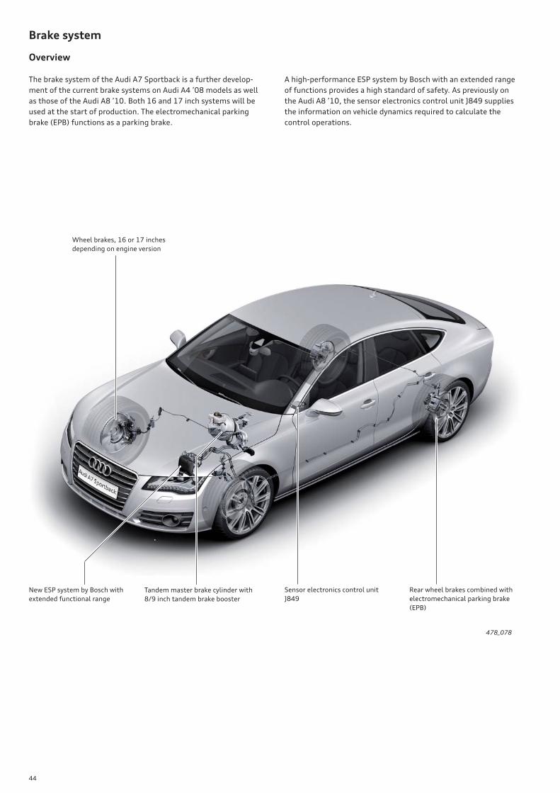
Brake system
Overview
The brake system of the Audi A7 Sportback is a further develop-
ment of the current brake systems on Audi A4 ’08 models as well
as those of the Audi A8 ’10. Both 16 and 17 inch systems will be
used at the start of production. The electromechanical parking
brake (EPB) functions as a parking brake.
A high-performance ESP system by Bosch with an extended range
of functions provides a high standard of safety. As previously on
the Audi A8 ’10, the sensor electronics control unit J849 supplies
the information on vehicle dynamics required to calculate the
control operations.
478_078
New ESP system by Bosch with
extended functional range
Rear wheel brakes combined with
electromechanical parking brake
(EPB)
Sensor electronics control unit
J849
Tandem master brake cylinder with
8/9 inch tandem brake booster
Wheel brakes, 16 or 17 inches
depending on engine version

45
adaptive cruise control (ACC)
ACC will also be available as an option for the Audi A7 Sportback.
The dual sensor system previously introduced in the Audi A8 ’10 is
now also used on the Audi A7 Sportback.
Wheels and tyres
From start of production, the Audi A7 Sportback comes as stand-
ard with 17 inch lightweight aluminium forged wheels. 18 to
20 inch wheels are optionally available. Tire Mobility System (TMS)
is standard equipment; a space saver spare wheel is optionally
available.
Tyre pressure indicator
The familiar second generation tyre pressure monitoring system,
the "tyre pressure indicator", is also used on the Audi A7 Sport-
back. The system is fi tted as standard on this model world-wide.
The system is identical to those already in use on other Audi
models in terms of its design, function, operation and driver
information, as well as its scope of servicing and diagnostics.
478_079
478_080

46
!
478_045
478_052
Head-up display
Introduction
The term "head-up display" describes optical systems which project
information from various automotive systems into the driver's
extended fi eld of vision. To view this information, the driver does
not have to change his/her head position signifi cantly and can
continue to focus on the road ahead while maintaining an upright
posture. Since the driver's head can remain "up" and need only be
lowered slightly, the system is referred to as a "head-up" display.
Windscreen projection system control unit J898
The central element of the head-up display is the windscreen
projection control unit J898. All optical, mechanical and electrical
components required for the head-up display are accommodated in
this control unit. It is located in the dash panel directly in front of
the instrument cluster.
The windscreen projection control unit J898 is self-diagnosable and
addressed with address word 82.
The use of special windscreens on models with a head-up display
give the impression that the head-up display is not actually in the
windscreen area, but at a comfortable distance of between two
and two and a half metres away from the driver. The head-up
display appears to hover over the bonnet.
Note
If a component of control unit J898 malfunctions, the complete control unit must always be replaced.
The windscreen has to be replaced when replacing control unit J898. For further information about removing control unit
J898, please refer to the relevant Workshop Manual.
Electrical system
47
!
478_050478_046
478_051478_047
478_048478_049
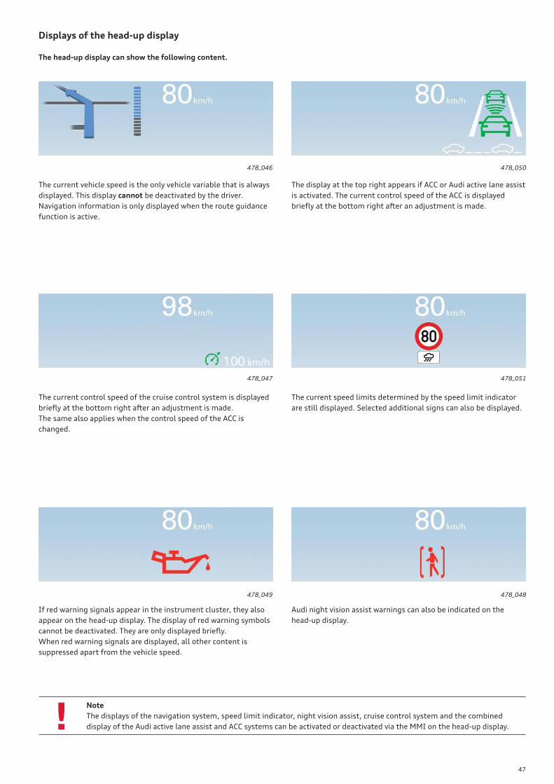
Note
The displays of the navigation system, speed limit indicator, night vision assist, cruise control system and the combined
display of the Audi active lane assist and ACC systems can be activated or deactivated via the MMI on the head-up display.
Displays of the head-up display
The current vehicle speed is the only vehicle variable that is always
displayed. This display cannot be deactivated by the driver.
Navigation information is only displayed when the route guidance
function is active.
The current control speed of the cruise control system is displayed
briefl y at the bottom right after an adjustment is made.
The same also applies when the control speed of the ACC is
changed.
If red warning signals appear in the instrument cluster, they also
appear on the head-up display. The display of red warning symbols
cannot be deactivated. They are only displayed briefl y.
When red warning signals are displayed, all other content is
suppressed apart from the vehicle speed.
The display at the top right appears if ACC or Audi active lane assist
is activated. The current control speed of the ACC is displayed
briefl y at the bottom right after an adjustment is made.
The current speed limits determined by the speed limit indicator
are still displayed. Selected additional signs can also be displayed.
Audi night vision assist warnings can also be indicated on the
head-up display.
The head-up display can show the following content.

48
!
Speed limit display
System components
The speed limit indicator utilises the image processing system and
the MMI Navigation Plus system known from the Audi A8 ’10.
The image processing system consists of the camera control unit
J852 for recording the area in front of the vehicle and the image
processing control unit J851 for the evaluation of camera images.
The camera images are transferred from the camera control unit to
the image processing control unit, where they are analysed for
road signs indicating speed limits.
The software of the speed limit indicator function is also inte-
grated in the image processing control unit J851.
The speed limit indicator function compares the visually detected
speed limits to the speed limits contained in the navigation data.
If both systems have diff erent information, the information of
either the image processing system or the navigation system is
prioritised and displayed depending on the actual situation.
If either source of information fails, the speed limit indicator will
continue to function but with reduced features. A message indicat-
ing this will appear on the display of the driver information system.
Camera control unit J852 Image processing control unit J851
478_037478_036
Note
No driver alert is given when the vehicle exceeds the speed limit! Neither does the system intervene in the driving process.
49
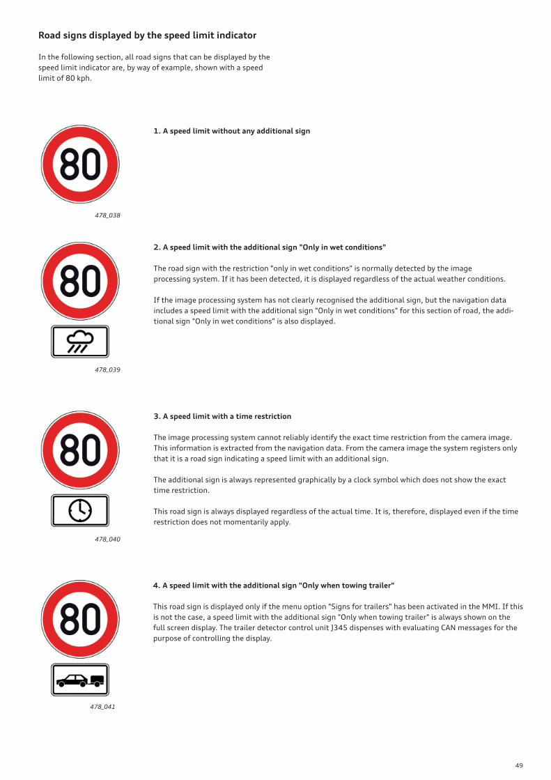
Road signs displayed by the speed limit indicator
In the following section, all road signs that can be displayed by the
speed limit indicator are, by way of example, shown with a speed
limit of 80 kph.
1. A speed limit without any additional sign
2. A speed limit with the additional sign "Only in wet conditions"
The road sign with the restriction "only in wet conditions" is normally detected by the image
processing system. If it has been detected, it is displayed regardless of the actual weather conditions.
If the image processing system has not clearly recognised the additional sign, but the navigation data
includes a speed limit with the additional sign "Only in wet conditions" for this section of road, the addi-
tional sign "Only in wet conditions" is also displayed.
3. A speed limit with a time restriction
The image processing system cannot reliably identify the exact time restriction from the camera image.
This information is extracted from the navigation data. From the camera image the system registers only
that it is a road sign indicating a speed limit with an additional sign.
The additional sign is always represented graphically by a clock symbol which does not show the exact
time restriction.
This road sign is always displayed regardless of the actual time. It is, therefore, displayed even if the time
restriction does not momentarily apply.
4. A speed limit with the additional sign "Only when towing trailer"
This road sign is displayed only if the menu option "Signs for trailers" has been activated in the MMI. If this
is not the case, a speed limit with the additional sign "Only when towing trailer" is always shown on the
full screen display. The trailer detector control unit J345 dispenses with evaluating CAN messages for the
purpose of controlling the display.
478_038
478_039
478_040
478_041
50
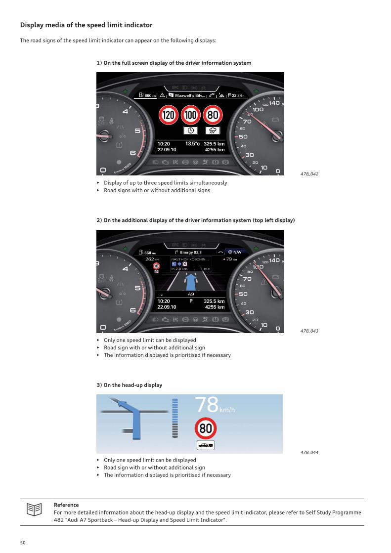
Display media of the speed limit indicator
The road signs of the speed limit indicator can appear on the following displays:
1) On the full screen display of the driver information system
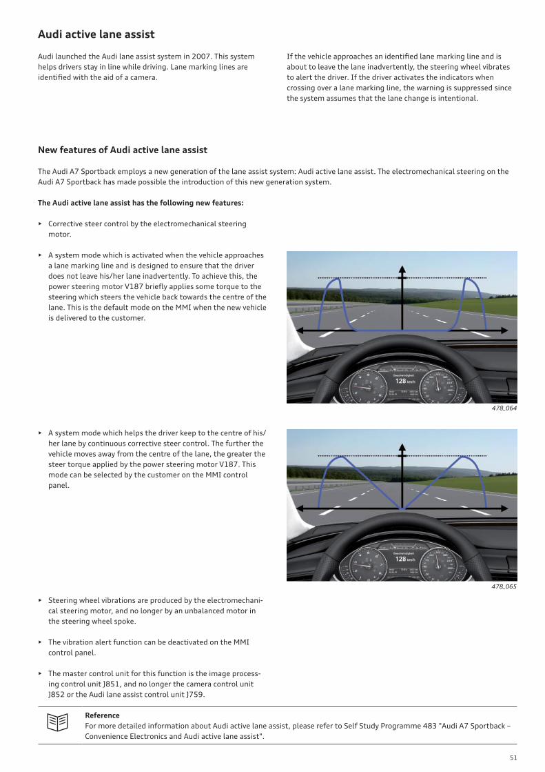
2) On the additional display of the driver information system (top left display)
• Display of up to three speed limits simultaneously
• Road signs with or without additional signs
• Only one speed limit can be displayed
• Road sign with or without additional sign
• The information displayed is prioritised if necessary
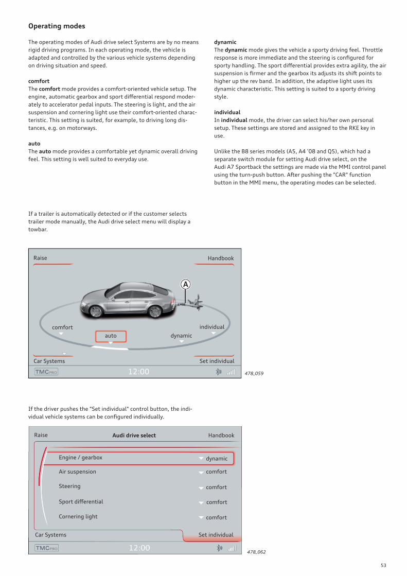
• Only one speed limit can be displayed
• Road sign with or without additional sign
• The information displayed is prioritised if necessary
3) On the head-up display
478_042
478_043
478_044
Reference
For more detailed information about the head-up display and the speed limit indicator, please refer to Self Study Programme
482 "Audi A7 Sportback – Head-up Display and Speed Limit Indicator".
51
Audi active lane assist
Audi launched the Audi lane assist system in 2007. This system
helps drivers stay in line while driving. Lane marking lines are
identifi ed with the aid of a camera.
If the vehicle approaches an identifi ed lane marking line and is
about to leave the lane inadvertently, the steering wheel vibrates
to alert the driver. If the driver activates the indicators when
crossing over a lane marking line, the warning is suppressed since
the system assumes that the lane change is intentional.
Reference
For more detailed information about Audi active lane assist, please refer to Self Study Programme 483 "Audi A7 Sportback –
Convenience Electronics and Audi active lane assist".
New features of Audi active lane assist
The Audi A7 Sportback employs a new generation of the lane assist system: Audi active lane assist. The electromechanical steering on the
Audi A7 Sportback has made possible the introduction of this new generation system.
The Audi active lane assist has the following new features:
• Corrective steer control by the electromechanical steering
motor.
• A system mode which is activated when the vehicle approaches
a lane marking line and is designed to ensure that the driver
does not leave his/her lane inadvertently. To achieve this, the
power steering motor V187 briefl y applies some torque to the
steering which steers the vehicle back towards the centre of the
lane. This is the default mode on the MMI when the new vehicle
is delivered to the customer.
• A system mode which helps the driver keep to the centre of his/
her lane by continuous corrective steer control. The further the
vehicle moves away from the centre of the lane, the greater the
steer torque applied by the power steering motor V187. This
mode can be selected by the customer on the MMI control
panel.
• Steering wheel vibrations are produced by the electromechani-
cal steering motor, and no longer by an unbalanced motor in
the steering wheel spoke.
• The vibration alert function can be deactivated on the MMI
control panel.
• The master control unit for this function is the image process-
ing control unit J851, and no longer the camera control unit
J852 or the Audi lane assist control unit J759.
478_064
478_065

52
Audi drive select
The Audi drive select fi rst off ered on the Audi A5 will also be
available on the Audi A7 Sportback. Audi drive select allows diff er-
ent vehicle setups to be confi gured.
There are three modes - comfort, auto und dynamic. The driver can
select these via the MMI control panel and, for example, switch
from a sporty to a comfort-oriented driving mode. In addition to
this, the driver can confi gure the vehicle setup to suit his/her
personal preferences in individual mode.
For instance, a sporty engine setup can be combined with a light
steering action. The trim level dictates which systems are confi g-
urable by Audi drive select. In all cases, however, the engine,
gearbox and steering systems are controlled.
Optionally, the following systems can be set via Audi drive select:
sport diff erential, cornering light, reversible belt pretensioners
and adaptive air suspension.
478_061
Audi pre sense basic
Sport diff erential Automatic gearbox Selection list
drive select
Cornering light
Accelerator/engineadaptive air suspensionServotronic
Variable
deployment program
Variable
transverse distribution
Variable
shift program
via MMI terminal
Variable
swivelling action
can be selected
via CAR menu
Variable
characteristic
Variable
damper rate
Variable
steering torque
53
478_059
auto
comfort
dynamic
individual
Handbook
Car Systems Set individual
Operating modes
The operating modes of Audi drive select Systems are by no means
rigid driving programs. In each operating mode, the vehicle is
adapted and controlled by the various vehicle systems depending
on driving situation and speed.
comfort
The comfort mode provides a comfort-oriented vehicle setup. The
engine, automatic gearbox and sport diff erential respond moder-
ately to accelerator pedal inputs. The steering is light, and the air
suspension and cornering light use their comfort-oriented charac-
teristic. This setting is suited, for example, to driving long dis-
tances, e.g. on motorways.
auto
The auto mode provides a comfortable yet dynamic overall driving
feel. This setting is well suited to everyday use.
dynamic
The dynamic mode gives the vehicle a sporty driving feel. Throttle
response is more immediate and the steering is confi gured for
sporty handling. The sport diff erential provides extra agility, the air
suspension is fi rmer and the gearbox its adjusts its shift points to
higher up the rev band. In addition, the adaptive light uses its
dynamic characteristic. This setting is suited to a sporty driving
style.
individual
In individual mode, the driver can select his/her own personal
setup. These settings are stored and assigned to the RKE key in
use.
Unlike the B8 series models (A5, A4 ’08 and Q5), which had a
separate switch module for setting Audi drive select, on the
Audi A7 Sportback the settings are made via the MMI control panel
using the turn-push button. After pushing the "CAR" function
button in the MMI menu, the operating modes can be selected.
If a trailer is automatically detected or if the customer selects
trailer mode manually, the Audi drive select menu will display a
towbar.
If the driver pushes the "Set individual" control button, the indi-
vidual vehicle systems can be confi gured individually.
478_062
Audi drive select
Engine / gearbox dynamic
Handbook
Car Systems Set individual
Air suspension
Steering
Sport diff erential
Cornering light
comfort
comfort
comfort
comfort
Raise
Raise

54
Characteristic
Engine and gearbox respond more immediately or more moder-
ately to accelerator pedal inputs. The power steering (servotronic)
is adapted to the driving situation and is lighter or fi rmer depend-
ing on which setting is selected.
The adaptive air suspension (Air suspension in the MMI) is an
electronically controlled air suspension and damping system. It is
set depending on what mode is selected and on the driver's steer-
ing, brake and accelerator inputs, as well as on road surface,
vehicle speed and payload.
The vehicle's ground clearance varies according to selected mode
and speed. If the driver is driving in auto or dynamic mode at a
speed of over 120 kph for longer than 30 seconds, the motorway
ride height is set automatically. If the vehicle's speed drops below
70 kph for longer than 120 seconds, ground clearance is automati-
cally increased.
In dynamic mode, the deployment thresholds of the reversible
belt pretensioners are adjusted according to transverse dynamics.
As an integral part of the all-wheel drive (quattro®), the sport
diff erential distributes drive power to the rear axle depending on
the situation. The distribution of power varies depending on which
mode has been selected. A high level of agility and acceleration are
achieved when cornering. The vehicle responds very quickly to
steering inputs.
The cornering light adapts to the curvature of the corner at speeds
of between 10 kph and 110 kph. The swivel action of the light and
the illumination level are also adapted to this mode.
The following table provides an overview of the characteristics
in each mode.
comfort auto dynamic
Engine / gearbox balanced balanced sporty
Air suspension1) comfortable balanced sporty
Steering comfortable balanced sporty
Sport diff erential balanced agile sporty
Cornering light comfortable balanced sporty
Reversible
belt pretensioners
standard standard Adapted
deployment
1) The control strategy of the air suspension system is described in SSP 480 "Audi A7 Sportback – Suspension".

55
System integration
478_063
Onboard power supply control unitJ519
Data bus diagnostic interfaceJ533
Information electronicscontrol unit 1J794
Front rightbelt pretensionercontrol unitJ855
Front leftbelt pretensionercontrol unit J854
Cornering lightand headlight range control unitJ745
Four wheel drivecontrol unitJ492
Adaptive suspen-sion control unitJ197
Engine control unitJ623
Power steering control unitJ500
Dual clutch gear-box mechatronicsJ743
Co
nv
en
ien
ce C
AN
bu
sP
ow
ert
rain
CA
N b
us
Fle
xR
ay
Ex
ten
de
d C
AN
bu
s
MOST bus
The onboard power supply control unit J519 performs the central-
ised function of Audi drive select. Information electronics control
unit 1 reads in the driver input information and transfers it to the
onboard power supply control unit via the MOST bus, the data bus
diagnostic interface (gateway) and the convenience CAN bus.
The onboard power supply control unit generates the relevant
commands from this information and relays them to the gateway
via the CAN bus. The gateway distributes these commands via the
extended CAN bus, the powertrain CAN bus and the FlexRay bus to
the control units participating in Audi drive select.
As soon as all switching conditions have been met, the user system
control unit confi rms the change-over by sending an acknowledge
message back to the onboard power supply control unit via the
gateway.
In this way, the onboard power supply control unit is kept informed
as to which user system is operating in which characteristic, thus
ensuring that change-overs always appear logical from the driver's
viewpoint.
On B8 series models, Audi drive select was always reset to auto
mode after removing the ignition key.
On the Audi A7 Sportback, the mode selected by the driver is
memorised for the next restart after turning off the ignition. Only
the engine and gearbox systems always start in the balanced
operating mode (this corresponds to selector position "D"). The
last mode setting as well as the individual settings are stored
automatically and assigned to the vehicle key.
• dynamic mode provides a sporty shift characteristic. The
gearbox position "S" is selected automatically.
• On models with a sport diff erential, dynamic mode is disa-
bled when towing a trailer.
• On some models, the vehicle reaches its top speed only in
auto and dynamic driving modes.
For further information on operation of Audi drive select, please
refer to the Owner's Manual.

56
Topology
Convenience CAN bus
Powertrain CAN bus Display and operation CAN bus
Diagnostics CAN bus
The diagram shows the topology of a model version with an exten-
sive equipment specifi cation.
Some of the control units shown here are optional and/or country-
specifi c equipment.
Extended CAN bus FlexRay
MOST bus
LIN bus
Sub-bus systems
Wiper motor control unitJ400
Rear spoiler adjust-ment control unitJ223
Sliding sunroof control unitJ245
Onboard power supply control unitJ519
Garage door open-ing control unitJ530
Refrigerant pres-sure/temperature senderG395
Air quality sensorG238
Air humidity sender in fresh air intake ductG657
Immobiliser reader coilD2
Electrical steering column lock control unitJ764
Alarm hornH12
Humidity senderG355
Anti-theft alarm sensorG578
Garage door operating unitE284
Electrically adjust-able steering col-umn control unitJ866
Light switchE1
Rain and light detector sensor G397
Selector lever sen-sors control unitJ587
Special vehicle control unitJ608
Door control unit, driver sideJ386
Rear hatch control unitJ605
Vehicle tracking system interface control unitJ843
Trailer detector control unitJ345
Front passenger seat adjustment control unit with memoryJ521
Seat and steering column adjustment control unit with memoryJ136
Taxi alarm remote control, control unitJ601
Door control unit, rear rightJ389
Door control unit, rear leftJ388
Convenience system central control unitJ393
Sunroof roller blind control unitJ394
Roof electronics control unitJ528
Door control unit, front passenger sideJ387
Multi-contour seat control unitdriver sideJ873
Multi-contour seat control unit, front passenger sideJ872
Fresh air blower control unitJ126
Flap control servomotors1 - 16
Multifunction steering wheel control unitJ453
Power output module for right LED headlight
Power output module for left LED headlight
Front right seat vent control unitJ799
Front left seat vent control unitJ800
Seat occupancy recognition control unit1)
J706
1) specifi c markets only
Key:

57
478_096
Park assist steering control unitJ791
Reversing camera system control unitJ772
Steering column electronics control unitJ527
Windscreen pro-jection system control unitJ898
Front left belt pretensioner control unitJ854
Camera control unitJ852
Headlight assist control unitJ844
Adaptive suspen-sion control unitJ197
Image processing control unitJ851
ACC control unit 2J850
ACC control unitJ428
Sensor electronics control unitJ849
ABS control unitJ104
Four-wheel drivecontrol unitJ492
Night vision system cameraR212
Night vision system control unitJ853
Headlight power module, rightJ668
Headlight power module, leftJ667
Cornering light and headlight range adjustment control unit J745
Voltage stabiliserJ532
AlternatorC
Battery monitor control unitJ367
Mechatronic unit for dual clutch gearboxJ743
Electromechanical park and handbrake control unitJ540
Steering angle senderG85
Engine control unitJ623
Power steering control unitJ500
MMI displayJ685
Digital sound pack-age control unitJ525
RadioR
Information electronics control unit 1J794
DVD auto changerR161
Control unit in dash panel insertJ285
Auxiliary heater control unitJ364
TV tunerR78
Rear air conditioner/Climatronic operat-ing and display unitE265
Rear vent servo-motors
Airbag control unitJ234
Data bus diagnostic interfaceJ533
Climatronic control unitJ255
Audi side assist control unit 2J770
Audi side assist control unitJ769
Front right belt pretensioner control unitJ855
Auxiliary heating radio controlled receiverR64
Diagnostic port

58
Introduction
Versions of the air conditioning system
Energy effi cient air conditioning systems are used on the Audi A7
Sportback. The entry-level Audi A7 Sportback has an automatic
front air conditioning system with separately controllable tem-
perature zones.
The system has two humidity senders – the humidity sender in the
fresh air intake duct G657 and the air humidity sender G355. In
the automatic front air conditioning system with separately con-
trollable temperature zones, rear ventilation is provided by outlets
in the centre console.
As an option, the customer can order a front and rear air condition-
ing system with a second control panel in the cabin.
Climatronic control unit J255
Rear upper body vent Rear air conditioner/Climatronic operating and display unit E265
Climatronic control unit J255
In addition to the automatic front air conditioning system, the four
zone air conditioning system has a rear air conditioner/Climatronic
operating and display unit E265 with the following functions:
• temperature setting
• Blower adjustment
• Separate rear left and right air distribution adjustment
To provide air conditioning in the rear, the four zone air condition-
ing system has air outlets in the B posts. The four zone air condi-
tioning system has additional deluxe options:
• Automatic recirculation control by air quality sensor G238
• Residual heat function
• Separate footwell temperature control
• Glove compartment cooling system
• Three diff erent air conditioning modes: soft, medium and
intensive
Reference
For further information about the air conditioning system of the Audi A7 Sportback, please refer to Self Study Programme
484 "Audi A7 Sportback Occupant Protection, Infotainment, Air Conditioning".
478_068 478_069
Dual zone air conditioning system(basic air conditioning system)
Four zone air conditioning system(deluxe air conditioning system)
Air conditioning
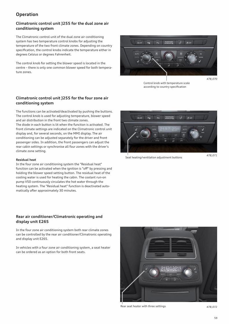
59
Operation
Climatronic control unit J255 for the dual zone air
conditioning system
The Climatronic control unit of the dual zone air conditioning
system has two temperature control knobs for adjusting the
temperature of the two front climate zones. Depending on country
specifi cation, the control knobs indicate the temperature either in
degrees Celsius or degrees Fahrenheit.
The control knob for setting the blower speed is located in the
centre – there is only one common blower speed for both tempera-
ture zones.
478_070
478_071
478_072
Climatronic control unit J255 for the four zone air
conditioning system
The functions can be activated/deactivated by pushing the buttons.
The control knob is used for adjusting temperature, blower speed
and air distribution in the front two climate zones.
The diode in each button is lit when the function is activated. The
front climate settings are indicated on the Climatronic control unit
display and, for several seconds, on the MMI display. The air
conditioning can be adjusted separately for the driver and front
passenger sides. In addition, the front passengers can adjust the
rear cabin settings or synchronise all four zones with the driver's
climate zone setting.
Residual heat
In the four zone air conditioning system the "Residual heat"
function can be activated when the ignition is "off " by pressing and
holding the blower speed setting button. The residual heat of the
cooling water is used for heating the cabin. The coolant run-on
pump V50 continuously circulates the hot water through the
heating system. The "Residual heat" function is deactivated auto-
matically after approximately 30 minutes.
Rear air conditioner/Climatronic operating and
display unit E265
In the four zone air conditioning system both rear climate zones
can be controlled by the rear air conditioner/Climatronic operating
and display unit E265.
In vehicles with a four zone air conditioning system, a seat heater
can be ordered as an option for both front seats.
Control knob with temperature scale
according to country specifi cation
Seat heating/ventilation adjustment buttons
Rear seat heater with three settings
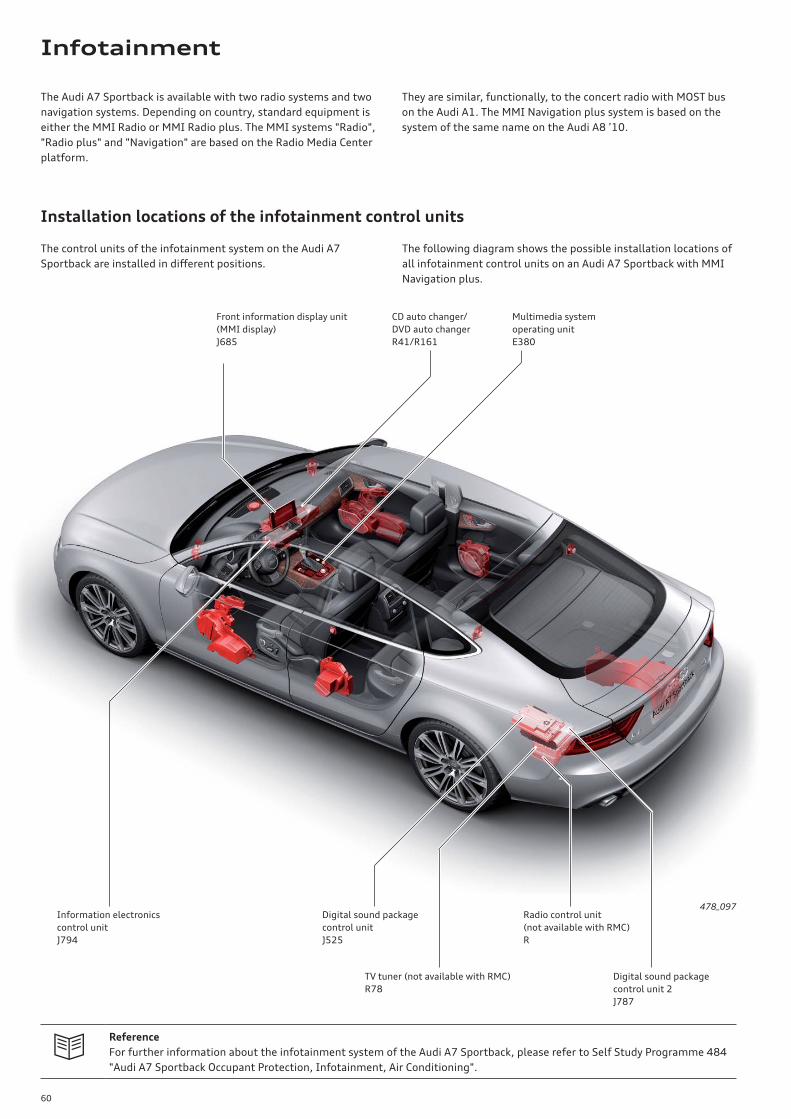
60
The control units of the infotainment system on the Audi A7
Sportback are installed in diff erent positions.
Front information display unit
(MMI display)
J685
Information electronics
control unit
J794
CD auto changer/
DVD auto changer
R41/R161
Digital sound package
control unit
J525
Multimedia system
operating unit
E380
TV tuner (not available with RMC)
R78
Digital sound package
control unit 2
J787
Radio control unit
(not available with RMC)
R
478_097
The Audi A7 Sportback is available with two radio systems and two
navigation systems. Depending on country, standard equipment is
either the MMI Radio or MMI Radio plus. The MMI systems "Radio",
"Radio plus" and "Navigation" are based on the Radio Media Center
platform.
They are similar, functionally, to the concert radio with MOST bus
on the Audi A1. The MMI Navigation plus system is based on the
system of the same name on the Audi A8 ’10.
The following diagram shows the possible installation locations of
all infotainment control units on an Audi A7 Sportback with MMI
Navigation plus.
Installation locations of the infotainment control units
Reference
For further information about the infotainment system of the Audi A7 Sportback, please refer to Self Study Programme 484
"Audi A7 Sportback Occupant Protection, Infotainment, Air Conditioning".
Infotainment

61
478_098 478_099
478_099
478_100
Maneouvres list 478_101
Attenzeller Strasse
Ingolstaedter Strasse
IN5
Doctor Ludwig Krauss-...
17 min
5 min
1 min
12 km
3.3 km
800 m
SettingDestination
1.0 km
14:04
TMC
405 m
96km
N
Front panel of J794 for MMI Radio Front panel of J794 for MMI Radio plus
Front panel of J794 for MMI Navigation
MMI Radio (RMC)
The MMI Radio of the Audi A7 Sportback has a similar confi gura-
tion and functions to the concert radio with MOST bus on the
Audi A1. The MMI Radio of the A7 Sportback has the following
equipment features:
• 6.5-inch display with 400 x 240 pixel resolution
• Control panel with six freely assignable radio station keys
• FM dual tuner with phase diversity (for FM), as well as a single
tuner for MW (medium wave) and LW (long wave) in Europe
• TP memo
• Single CD drive
• Integrated amplifi er with 4x 20 watts power output
• Car menu
MMI Radio plus (RMC)
Compared to MMI Radio, MMI Radio plus has the following diff er-
ent and/or additional features:
• Two SD card readers
• Integrated six-channel amplifi er for Audi Sound with 180 watts
power output
• Bluetooth interface
• Speech dialogue system
• Driver information system with monochrome screen in the dash
panel insert
• Digital satellite radio (available in USA and Canada only)
• AUX In on centre console
• Provision for optional equipment
MMI Navigation (RMC)
The MMI Navigation infotainment system has a navigation func-
tion in addition to the features of MMI Radio plus. The navigation
map is stored on an SD card. In Europe, for example, a 4GB SDHC
card is used. The navigation system operates only with the SD card
inserted.
The navigation system uses a 2D map display and can be confi g-
ured to display maps in 3D birdview. Other special features of the
navigation system include a maneouvres lists and detailed inter-
section maps. This information is displayed in split screen mode.
Trip destinations can be entered using the speech dialogue system.
MMI radios and navigation systems
Back panel of J794 for MMI Navigation
AM/FM1DAB FM2 AMIDisplay MOST bus
Navigation
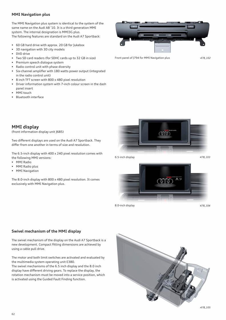
62
MMI Navigation plus
The MMI Navigation plus system is identical to the system of the
same name on the Audi A8 ’10. It is a third generation MMI
system. The internal designation is MMI3G plus.
The following features are standard on the Audi A7 Sportback:
• 60 GB hard drive with approx. 20 GB for Jukebox
• 3D navigation with 3D city models
• DVD drive
• Two SD card readers (for SDHC cards up to 32 GB in size)
• Premium speech dialogue system
• Radio control unit with phase diversity
• Six-channel amplifi er with 180 watts power output (integrated
in the radio control unit)
• 8 inch TFT screen with 800 x 480 pixel resolution
• Driver information system with 7-inch colour screen in the dash
panel insert
• MMI touch
• Bluetooth interface
Front panel of J794 for MMI Navigation plus 478_102
MMI display(front information display unit J685)
Two diff erent displays are used on the Audi A7 Sportback. They
diff er from one another in terms of size and resolution.
The 6.5-inch display with 400 x 240 pixel resolution comes with
the following MMI versions:
• MMI Radio
• MMI Radio plus
• MMI Navigation
The 8.0-inch display with 800 x 480 pixel resolution. It comes
exclusively with MMI Navigation plus.
478_103
478_104
6.5-inch display
8.0-inch display
Swivel mechanism of the MMI display
The swivel mechanism of the display on the Audi A7 Sportback is a
new development. Compact fi tting dimensions are achieved by
using a cable pull drive.
The motor and both limit switches are activated and evaluated by
the multimedia system operating unit E380.
The swivel mechanisms of the 6.5 inch display and the 8.0 inch
display have diff erent driving gears. To replace the display, the
rotation mechanism must be moved into a service position, which
is activated using the Guided Fault Finding function.
478_105
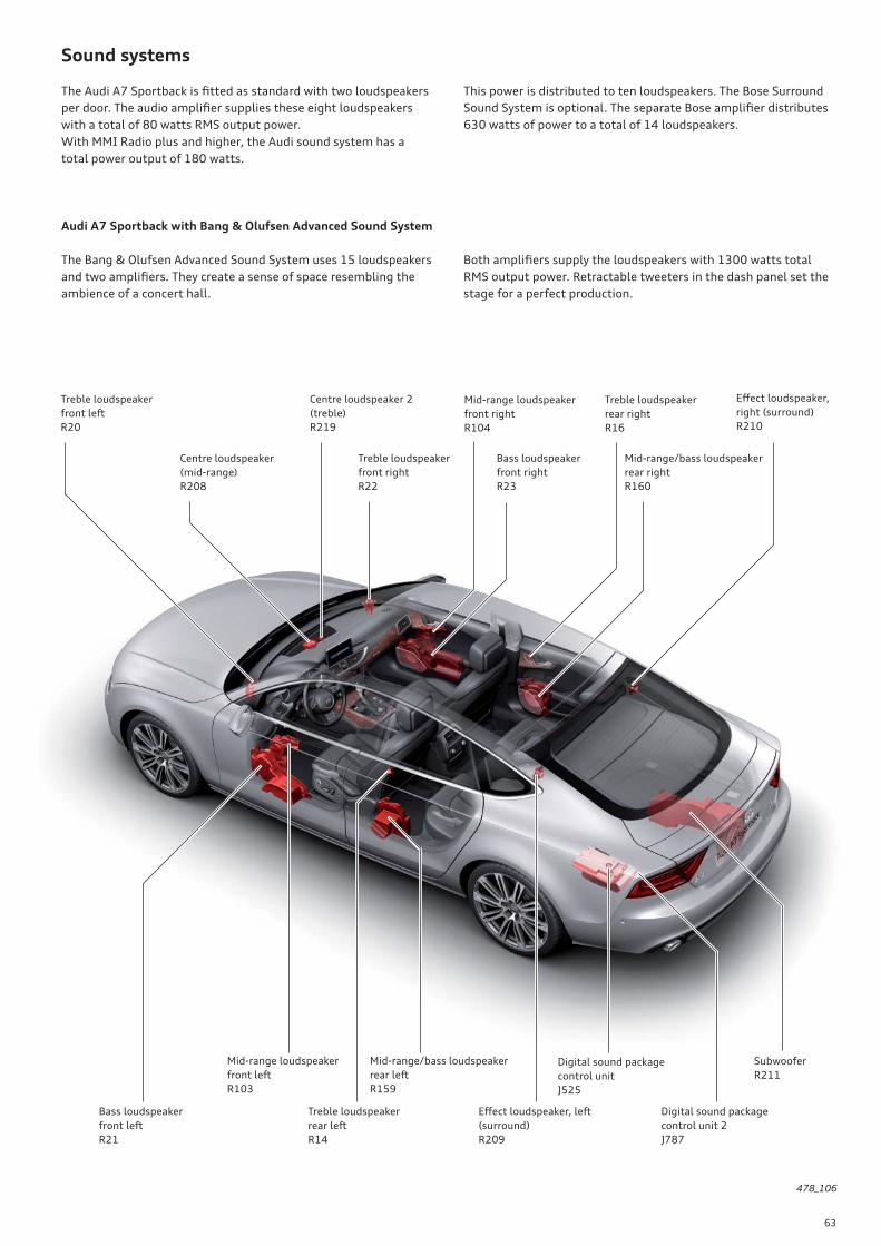
63
Sound systems
The Audi A7 Sportback is fi tted as standard with two loudspeakers
per door. The audio amplifi er supplies these eight loudspeakers
with a total of 80 watts RMS output power.
With MMI Radio plus and higher, the Audi sound system has a
total power output of 180 watts.
This power is distributed to ten loudspeakers. The Bose Surround
Sound System is optional. The separate Bose amplifi er distributes
630 watts of power to a total of 14 loudspeakers.
Audi A7 Sportback with Bang & Olufsen Advanced Sound System
The Bang & Olufsen Advanced Sound System uses 15 loudspeakers
and two amplifi ers. They create a sense of space resembling the
ambience of a concert hall.
Both amplifi ers supply the loudspeakers with 1300 watts total
RMS output power. Retractable tweeters in the dash panel set the
stage for a perfect production.
Centre loudspeaker
(mid-range)
R208
Treble loudspeaker
front left
R20
Centre loudspeaker 2
(treble)
R219
Bass loudspeaker
front left
R21
Bass loudspeaker
front right
R23
Eff ect loudspeaker,
right (surround)
R210
Treble loudspeaker
front right
R22
Treble loudspeaker
rear left
R14
Mid-range loudspeaker
front right
R104
Treble loudspeaker
rear right
R16
Digital sound package
control unit 2
J787
Eff ect loudspeaker, left
(surround)
R209
Digital sound package
control unit
J525
Subwoofer
R211
Mid-range/bass loudspeaker
rear left
R159
Mid-range loudspeaker
front left
R103
478_106
Mid-range/bass loudspeaker
rear right
R160

64
!Note
The specifi cations in the current service literature always apply.
Inspection and maintenance
• Time-based servicing events due on expiration of pre-deter-
mined time intervals, e.g. inspection every 2 years.
Here, for example, the display changes to:
SERVICE DUE:
since 1000 km / 5 days.
The fi eld for the mileage-based servicing events now displays
30,000 km for new vehicles and counts down in increments of
100 km. The value in the fi eld for the time-based servicing events
is now 730 days (2 years) for new vehicles and is updated on a daily
basis.
In new vehicles, the next oil change due box (fl exible servicing
event) is initially blank. This interval has to be computed from the
driving profi le and engine load and is not displayed until 500 km
have been covered. The display "Oil change due" then switches to
"Next oil change". The message "Oil change due" does not reappear
until the due date for the next oil change has expired. Likewise,
"Service due" does not reappear until after the due date for the
next service.
Overview of service intervals
Example of a service interval display in the MMI
Mileage-based
servicing event
Flexible servicing eventOil change due:
--/--
Next service:
in 30,000 km / in 730 days
Service intervalsServicing & checks
HandbookCar
Time-based
servicing event
478_058
Audi A7 Sportback 2.8l FSI
150 kW
Audi A7 Sportback 3.0l TFSI
200 kW
Audi A7 Sportback 3.0l TDI
150 kW / 180 kW
Oil change interval, fl exible 15,000 km / 1 year – 30,000 km / 2 years (market-dependent)
Service interval, fi xed 30,000 km / 2 years 30,000 km / 2 years 30,000 km / 2 years
Dust and pollen fi lter 30,000 km / 2 years 30,000 km / 2 years 30,000 km / 2 years
Brake fl uid Change after 3 years for the fi rst time (depending on market), then every 2 years
Air fi lter 90,000 km 90,000 km 90,000 km
Spark plugs 90,000 km 90,000 km -
Fuel fi lter Lifetime Lifetime 60,000 km
Gear oils
• multitronic
• 7 speed dual clutch gearbox
• ATF1)
• MTF2)
60,000 km
60,000 km
Lifetime
60,000 km
60,000 km
Lifetime
60,000 km
60,000 km
Lifetime
Timing drive chain Lifetime Lifetime Lifetime
1) ATF = Automatic Transmission Fluid
2) MTF = Manual Transmission Fluid
The following servicing work is displayed separately:
• Oil change as a fl exible servicing event dependent on driving
profi le.
• Mileage-based servicing events due after multiples of
30,0000 km
Service

65
Special tools and workshop equipment
Isolator box VAS 6606
Workshop equipment
With 198-pin terminals (UDS control unit) for diagnostics on the
new-generation control units The illustration shows the prototype
version.
478_092
Guide plate VAS 5161-29
Engine holder VAS 6095-1-11
478_117
478_118
Sealing bolt VAS 5161-29-1
478_119
Calibration board for head-up display VAS 6656
478_120
Retainer VAS 6395/6
478_114
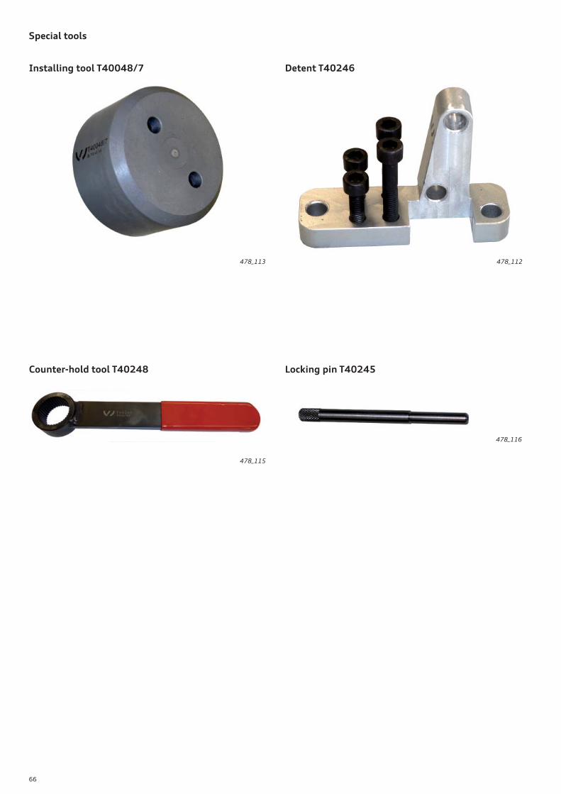
66
Locking pin T40245
478_116
Installing tool T40048/7
478_113
Detent T40246
478_112
Counter-hold tool T40248
478_115
Special tools
67
Self Study Programmes
For further information about the technology in the Audi A7 Sportback, please refer to the following Self Study Programmes.
SSP 479 Audi 3.0l V6 TDI engine (second generation), order number: A10.5S00.72.20
SSP 480 Audi A7 Sportback Chassis, order number: A10.5S00.73.20
SSP 481 Audi A7 Sportback Onboard Power Supply and Networking, order number: A10.5S00.74.20
478_034
SSP 482 Audi A7 Sportback Head-up Display and Speed Limit Indicator, order number: A10.5S00.75.20
SSP 483 Audi A7 Sportback Convenience Electronics and Audi active lane assist, order number: A10.5S00.76.20
SSP 484 Audi A7 Sportback Occupant Protection, Infotainment and Air Conditioning, order number: A10.5S00.77.20
478_093478_111
478_081 478_035478_082
Annex

Audi
Audi
Vorsprung durch Technik
Service Training
47
8
Audi A7 Sportback
All rights reserved.
Technical specifi cations are subject to
change.
Copyright
AUDI AG
I/VK-35
AUDI AG
D-85045 Ingolstadt
Technical status 09/11
Printed in Germany
A10.5S00.71.20
Self Study Programme 478