august 2019 backward inclined swsi class 1-3 fans
TRANSCRIPT
BULLETIN 13000
AUGUST 2019
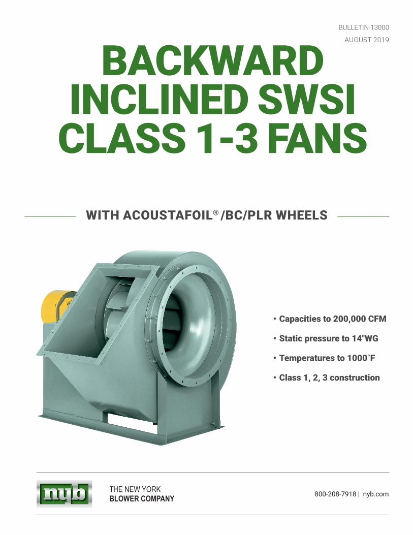
BACKWARD INCLINED SWSI
CLASS 1-3 FANS
• Capacities to 200,000 CFM
• Static pressure to 14"WG
• Temperatures to 1000˚F
• Class 1, 2, 3 construction
WITH ACOUSTAFOIL® /BC/PLR WHEELS
800-208-7918 | nyb.comTHE NEW YORK BLOWER COMPANY

2 NEW YORK BLOWER | SINGLE-WIDTH FANS
FAN
INFO
RM
ATIO
N
BACKWARD INCLINED SWSI FANS
Backward Inclined SWSI (single width, single inlet) centrifugal fans are designed for a wide range of applications from commercial-building ventilation to industrial dust-collection systems. Three classes of construction combined with three types of wheels provides maximum selection flexibility and optimum performance.
Size 24, Arrangement 9 SWSI fan with optional belt drives, belt guard, shaft and bearing guard, flanged outlet, bolted cleanout door, and motor.
Size 24, Arrangement 8 SWSI fan with optional stainless-steel airstream, flanged inlet, flanged outlet, shaft and bearing guard, coupling, coupling guard, and motor.
DESIGN FEATURES • Three wheel choices:
LJ High-efficiency AcoustaFoil® wheels, Sizes 12″-89″.*
LJ Versatile backward curved wheels, Sizes 18″-73″. LJ Rugged PLR backward inclined wheels, Sizes 12″-89″.*
• Capacities to 200,000 CFM.• Pressures to 14″ WG.• Complete AMCA Class 1, 2, and 3 performance.• Efficiencies beyond 85%.• Temperatures to 1000°F.• Choice of direct-drive [see page 6] or belt-drive [see page 7]
arrangements.• Available in clockwise and counterclockwise rotations in any
of seven standard discharge positions. * See pages 6 and 7 for additional sizes and classes.
CONSTRUCTION FEATURES • Heavy-gauge welded components provide structural strength
and durability.• Continuously welded housings provide the strongest possible
construction. • Shafting is straightened to close-tolerance to minimize “run
out” and ensure smooth operation. • Lifting eyes are standard on all fans. • Wheels are dynamically balanced and all fans are checked at
the specified running speed.• Bearings are selected to provide long service life through the
entire operating range of the fan.
FAN INFORMATION
The New York Blower Company certifies that the Single-Width AcoustaFoil Fans shown on pages 16 through 18 and Single-Width PLR Fans shown on pages 19 through 21 are licensed to bear the AMCA Seal. The ratings shown are based on tests and procedures performed in accordance with AMCA Publication 211 and comply with the requirements of the AMCA Certified Ratings Program.
AcoustaFoil ® is a registered trademark of The New York Blower CompanyCopyright © 2019 by The New York Blower Company

3NYB.COM
WH
EEL
DES
IGN
WHEEL DESIGNCHOICE OF THREE WHEEL DESIGNS
Three wheel designs provide the widest choice in application suitability, efficiency, sound, and cost. All three feature the backward inclined, non-overloading horsepower characteristic where the horsepower reaches a peak and then decreases even as flow increases. This characteristic allows maximum brake horsepower calculation and motor selection that prevents electrical system overloading even if system pressure changes.
ACOUSTAFOIL
0%
20%
40%
60%
80%
100%
0% 20% 40% 60% 80% 100%CF M
BHP
and
ME
S T AT IC P R E S S U R E
B R AK E H O R S E P O WE R
ME C HANIC AL E FF IC IE NC Y
Backward Curved
0%
20%
40%
60%
80%
100%
0% 20% 40% 60% 80% 100%CF M
BHP
and
ME
STATIC PRESSURE
B R AK E H O R S E P O WE R
ME C HANIC AL E FF IC IE NC Y
PLR
0%
20%
40%
60%
80%
100%
0% 20% 40% 60% 80% 100%CF M
BHP
and
ME
STATIC PRESSURE
B R AK E H O R S E P O WE R
ME C HANIC AL E FF IC IE NC Y
Wheel Design—True aerodynamic airfoil-blade shape allows stable operation from wide-open to closed-off. Ideal for clean-air applications such as building ventilation with variable-air-volume system control or clean industrial-gas-handling.
Wheel Design—Flat, single-thickness, backwardly inclined blades are suited to applications from clean air to those where dust and limited material is pres-ent in the airstream and airfoil shapes are not recommended due to material build-up.
Wheel Design—Aerodynamic, single-surface blade shape offers alternative selection points to the AcoustaFoil for building ventilation and industrial gas-handling. Backward curved wheels also provide stable operation from wide-open to closed-off.
Efficiency—Dual aerodynamically designed blade surfaces provide the most efficient design of all wheel types. In addition, the AcoustaFoil design offers a broad peak efficiency range for selection.
Efficiency—Peak efficiency point is on the steeply rising portion of the pressure curve and vastly superior to forward curved and radial wheel designs.
Efficiency—Curved, single-thickness blade surface generates efficiency levels approaching the AcoustaFoil but with alternative operating points for greater choice.
Sound—Because of superior efficiency, AcoustaFoil wheels generate the lowest sound levels over a wide range of performance.
Sound—Sound levels are the lowest with the most efficient fan selections.
Sound—The backward curved wheel offers low sound levels approaching that of the AcoustaFoil.
Construction—Sizes 12 and 15 available in welded aluminum only. Sizes 18 to 89 available in all-welded steel and optional aluminum and stainless steel.
Construction—Sizes 12 to 89 available in all-welded steel and also optional aluminum and stainless steel.
Construction—Sizes 18 to 73 available in all-welded steel and also optional aluminum.
Performance Performance Performance
4 NEW YORK BLOWER | SINGLE-WIDTH FANS
AC
CES
SOR
IES
ACCESSORIESACCESSORIES
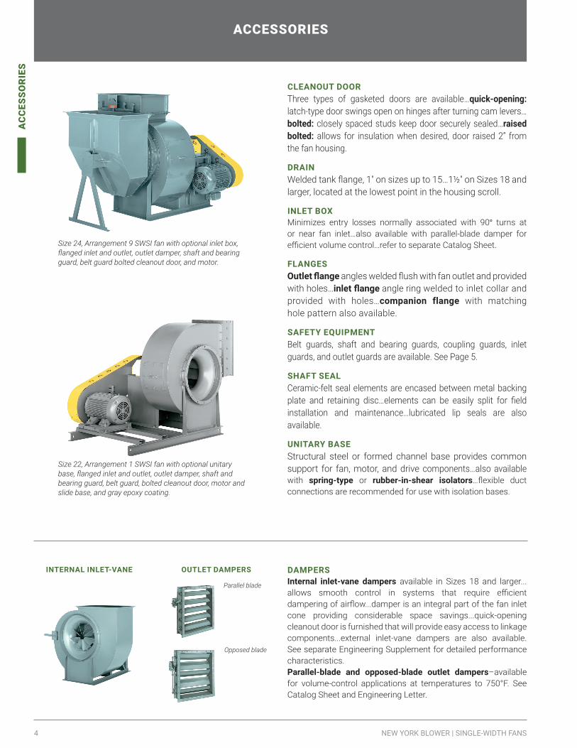
CLEANOUT DOORThree types of gasketed doors are available…quick-opening: latch-type door swings open on hinges after turning cam levers…bolted: closely spaced studs keep door securely sealed…raised bolted: allows for insulation when desired, door raised 2” from the fan housing.
DRAINWelded tank flange, 1″ on sizes up to 15…1½″ on Sizes 18 and larger, located at the lowest point in the housing scroll.
INLET BOXMinimizes entry losses normally associated with 90° turns at or near fan inlet…also available with parallel-blade damper for efficient volume control…refer to separate Catalog Sheet.
FLANGESOutlet flange angles welded flush with fan outlet and provided with holes…inlet flange angle ring welded to inlet collar and provided with holes…companion flange with matching hole pattern also available.
SAFETY EQUIPMENTBelt guards, shaft and bearing guards, coupling guards, inlet guards, and outlet guards are available. See Page 5.
SHAFT SEALCeramic-felt seal elements are encased between metal backing plate and retaining disc…elements can be easily split for field installation and maintenance…lubricated lip seals are also available.
UNITARY BASEStructural steel or formed channel base provides common support for fan, motor, and drive components…also available with spring-type or rubber-in-shear isolators…flexible duct connections are recommended for use with isolation bases.
Size 22, Arrangement 1 SWSI fan with optional unitary base, flanged inlet and outlet, outlet damper, shaft and bearing guard, belt guard, bolted cleanout door, motor and slide base, and gray epoxy coating.
Size 24, Arrangement 9 SWSI fan with optional inlet box, flanged inlet and outlet, outlet damper, shaft and bearing guard, belt guard bolted cleanout door, and motor.
INTERNAL INLET-VANE OUTLET DAMPERS
Parallel blade
Opposed blade
DAMPERSInternal inlet-vane dampers available in Sizes 18 and larger...allows smooth control in systems that require efficient dampering of airflow...damper is an integral part of the fan inlet cone providing considerable space savings...quick-opening cleanout door is furnished that will provide easy access to linkage components...external inlet-vane dampers are also available. See separate Engineering Supplement for detailed performance characteristics.Parallel-blade and opposed-blade outlet dampers–available for volume-control applications at temperatures to 750°F. See Catalog Sheet and Engineering Letter.

5NYB.COM
MO
DIF
ICAT
ION
SPLIT-HOUSING CONSTRUCTIONAvailable with standard construction for:Sizes 40-73 Class 1 and 2Sizes 36-73 Class 3Sizes 36-73 Class 1, 2, and 3Split housing is standard on fan sizes 80-89
TYPE ABottom Horizontal Up Blast Down Blast
Horizontal split allows removal of topsection without disturbing inlet connection...outlet connection must be broken on Up Blast fans only.
TYPE BTop Horizontal Top Angular Down Bottom Angular Up Top Angular Up Split allows removal of pie-shaped section without disturbing inlet or outlet connections.
MODIFICATIONMODIFICATIONS
nyb's catalog fans can be configured for specific industry or customer specifications for the petro-chemical, power, steel, food, marine, and nuclear industries. Some of these specifications include API-560, API-673 and AAR M-1003. nyb will manufacture our products using metric dimensions (when requested) and locally sourced accessories such as bearing, couplings, etc. to meet global or regional standard and/or requirements.
HANDLING CORROSIVESProtective coatings, special alloys, and FRP construction are available to combat corrosion problems.
Special coatings [up to 12 mil thickness]–special paints and spray coatings are available under a variety of trade names. nyb works with experienced coating applicators who can apply coatings to meet a wide range of requirements.
Alternate-material construction–Single-Width Fans can be constructed of aluminum or various stainless steels.
HEAT-FAN CONSTRUCTIONArrangement 1, 8, and 9 fans can be constructed for elevated-temperature operation with the addition of shaft cooler and guard and high-temperature paint for 650°F. (Class 1 and 2) or 1000°F. (Class 3) maximum airstream temperature. Arrangement 9 fans are also furnished with motor heat shield. If optional shaft seal is selected, a recessed cone is furnished. Note that the maximum safe wheel speeds decrease as airstream temperatures increase…see Chart I on page 15.
SPARK-RESISTANT CONSTRUCTION [SRC]Intended to minimize the potential for any two or more fan components to generate sparks within the airstream by rubbing or striking during operation.
The following types are available:
AMCA A [AIRSTREAM] SRC
To include all airstream parts constructed of a spark-resistant alloy...maximum temperature: 200°F.
AMCA B [WHEEL] SRC
To include the fan wheel constructed of a spark-resistant alloy and a buffer plate around the housing shaft-hole opening...maximum temperature: 200°F.
AMCA C [BUFFER] SRC
To include a spark-resistant alloy buffer affixed to the housing interior adjacent to the wheel backplate, a spark-resistant alloy inlet cone, and a buffer plate around the housing shaft-hole opening...maximum temperature: 650°F
ALL TYPES SRCFan is to be so constructed such that no bearings, drive components, or electrical apparatus are located in the airstream...the user must electrically ground all fan and system components.
NARROW-WIDTH CONSTRUCTIONWheel and housing widths can be adjusted to meet volume and pressure requirements at most efficient operating point.
SAFETY EQUIPMENTSafety accessories are available from nyb, but selection of the appropriate devices is the responsibility of the system-designer who is familiar with the particular installation, or application, and can provide for guards for all exposed moving parts as well as protection from access to high-velocity airstreams. Neither nyb nor its sales representatives is in a position to make such a determination. Users and/or installers should read “Recommended Safety Practices for Air Moving Devices” as published by the Air Movement and Control Association International, Arlington Heights, Illinois.
6 NEW YORK BLOWER | SINGLE-WIDTH FANS
AR
RA
NG
EMEN
TS
ARRANGEMENTS
DIRECT-DRIVE ARRANGEMENTS
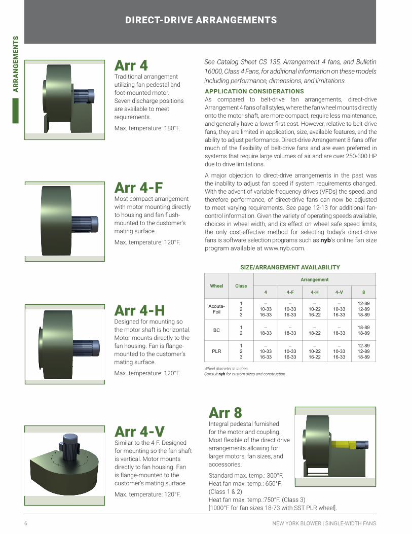
See Catalog Sheet CS 135, Arrangement 4 fans, and Bulletin 16000, Class 4 Fans, for additional information on these models including performance, dimensions, and limitations.
Arr 4 Traditional arrangement utilizing fan pedestal and foot-mounted motor. Seven discharge positions are available to meet requirements.
Max. temperature: 180°F.
Arr 4-HDesigned for mounting so the motor shaft is horizontal.Motor mounts directly to the fan housing. Fan is flange-mounted to the customer’s mating surface.
Max. temperature: 120°F.
Arr 4-FMost compact arrangement with motor mounting directly to housing and fan flush-mounted to the customer’s mating surface.
Max. temperature: 120°F.
Arr 4-V Similar to the 4-F. Designed for mounting so the fan shaft is vertical. Motor mounts directly to fan housing. Fan is flange-mounted to the customer’s mating surface.
Max. temperature: 120°F.
Arr 8Integral pedestal furnished for the motor and coupling. Most flexible of the direct drive arrangements allowing for larger motors, fan sizes, and accessories.
Standard max. temp.: 300°F.Heat fan max. temp.: 650°F. (Class 1 & 2)Heat fan max. temp.:750°F. (Class 3)[1000°F for fan sizes 18-73 with SST PLR wheel].
APPLICATION CONSIDERATIONSAs compared to belt-drive fan arrangements, direct-drive Arrangement 4 fans of all styles, where the fan wheel mounts directly onto the motor shaft, are more compact, require less maintenance, and generally have a lower first cost. However, relative to belt-drive fans, they are limited in application, size, available features, and the ability to adjust performance. Direct-drive Arrangement 8 fans offer much of the flexibility of belt-drive fans and are even preferred in systems that require large volumes of air and are over 250-300 HP due to drive limitations.
A major objection to direct-drive arrangements in the past was the inability to adjust fan speed if system requirements changed. With the advent of variable frequency drives (VFDs) the speed, and therefore performance, of direct-drive fans can now be adjusted to meet varying requirements. See page 12-13 for additional fan-control information. Given the variety of operating speeds available, choices in wheel width, and its effect on wheel safe speed limits, the only cost-effective method for selecting today’s direct-drive fans is software selection programs such as nyb's online fan size program available at www.nyb.com.
SIZE/ARRANGEMENT AVAILABILITY
Wheel ClassArrangement
4 4-F 4-H 4-V 8
Acouta-Foil
123
–10-3316-33
–10-3316-33
–10-2216-22
–10-3316-33
12-8912-8918-89
BC 12
–18-33
–18-33
–18-22
–18-33
18-8918-89
PLR123
–10-3316-33
–10-3316-33
–10-2216-22
–10-3316-33
12-8912-8918-89
Wheel diameter in inches.Consult nyb for custom sizes and construction
7NYB.COM
AR
RA
NG
EMEN
TS
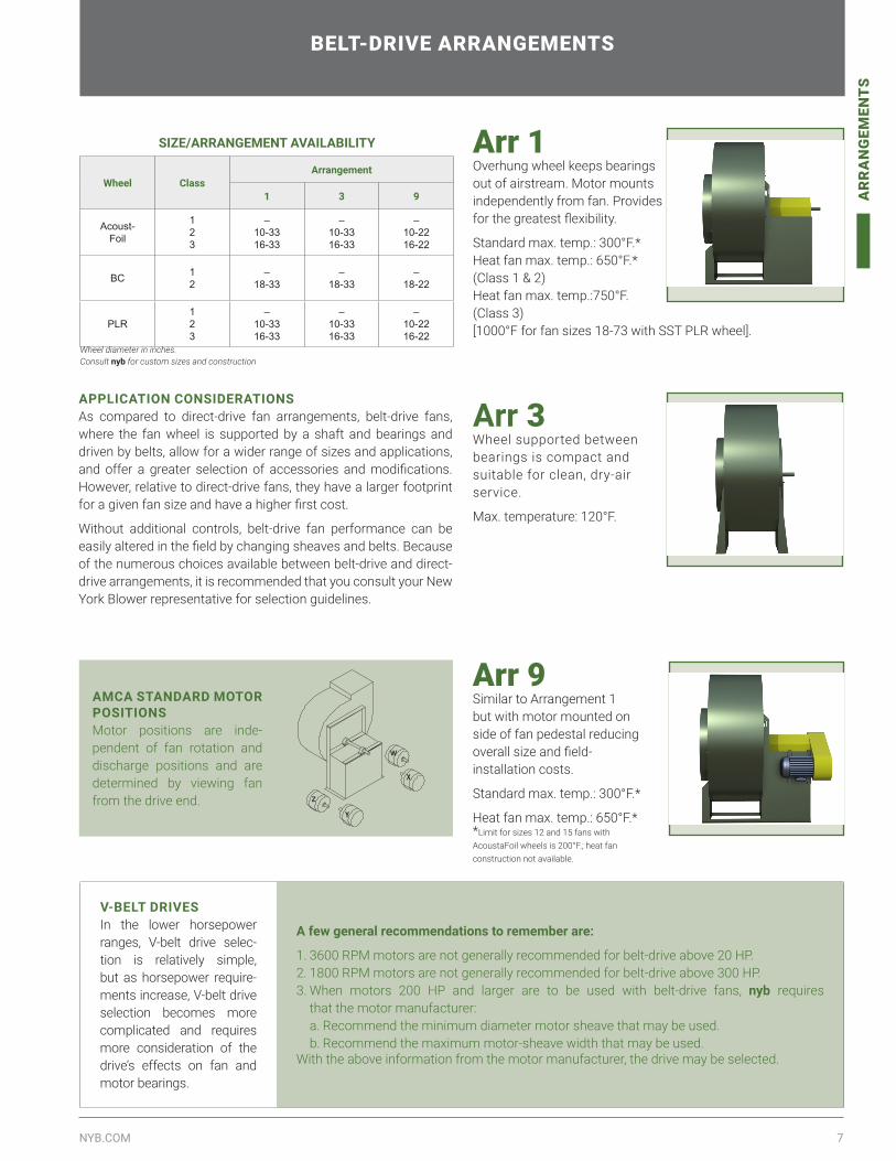
Arr 1 Overhung wheel keeps bearings out of airstream. Motor mounts independently from fan. Provides for the greatest flexibility.
Standard max. temp.: 300°F.*Heat fan max. temp.: 650°F.* (Class 1 & 2)Heat fan max. temp.:750°F. (Class 3)[1000°F for fan sizes 18-73 with SST PLR wheel].
BELT-DRIVE ARRANGEMENTS
APPLICATION CONSIDERATIONSAs compared to direct-drive fan arrangements, belt-drive fans, where the fan wheel is supported by a shaft and bearings and driven by belts, allow for a wider range of sizes and applications, and offer a greater selection of accessories and modifications. However, relative to direct-drive fans, they have a larger footprint for a given fan size and have a higher first cost.
Without additional controls, belt-drive fan performance can be easily altered in the field by changing sheaves and belts. Because of the numerous choices available between belt-drive and direct-drive arrangements, it is recommended that you consult your New York Blower representative for selection guidelines.
SIZE/ARRANGEMENT AVAILABILITY
Wheel ClassArrangement
1 3 9
Acoust-Foil
123
–10-3316-33
–10-3316-33
–10-2216-22
BC 12
–18-33
–18-33
–18-22
PLR123
–10-3316-33
–10-3316-33
–10-2216-22
Wheel diameter in inches.Consult nyb for custom sizes and construction
Arr 3Wheel supported between bearings is compact and suitable for clean, dry-air service.
Max. temperature: 120°F.
Arr 9Similar to Arrangement 1 but with motor mounted on side of fan pedestal reducing overall size and field-installation costs.
Standard max. temp.: 300°F.*
Heat fan max. temp.: 650°F.* *Limit for sizes 12 and 15 fans with AcoustaFoil wheels is 200°F.; heat fan construction not available.
V-BELT DRIVESIn the lower horsepower ranges, V-belt drive selec-tion is relatively simple, but as horsepower require-ments increase, V-belt drive selection becomes more complicated and requires more consideration of the drive’s effects on fan and motor bearings.
A few general recommendations to remember are:
1. 3600 RPM motors are not generally recommended for belt-drive above 20 HP. 2. 1800 RPM motors are not generally recommended for belt-drive above 300 HP. 3. When motors 200 HP and larger are to be used with belt-drive fans, nyb requires
that the motor manufacturer: a. Recommend the minimum diameter motor sheave that may be used. b. Recommend the maximum motor-sheave width that may be used.
With the above information from the motor manufacturer, the drive may be selected.
AMCA STANDARD MOTOR POSITIONSMotor positions are inde-pendent of fan rotation and discharge positions and are determined by viewing fan from the drive end. Z
Y
W
X

8 NEW YORK BLOWER | SINGLE-WIDTH FANS
DIM
ENSI
ON
S
DIMENSIONS
ARRANGEMENT 8 MOTOR PEDESTAL DIMENSIONSThese approximate dimensions can be used to estimate the overall size of Arrangement 8 fans. Add the appropriate dimensions below to the fan dimensions on pages 25 and 26.
Note: Coupling gap is based on the Falk Steelflex coupling sizes shown. As the gap will vary with other coupling sizes or types, so will the Arrangement 8 motor pedestal dimensions. Specific motor and coupling data is required to determine exact dimensions.
MOTOR PEDESTAL DIMENSIONS, CAPABILITIES
T
T
W
W
A
O- O
H- HH
K
Coupling gap
TYPICAL BASE PLAN
DIMENSIONS [INCHES]
Motor Frame SizeCoupling 0-0* H-H*
Size Gap Min. Max.Open TE
Min Max. Min. Max.213TS-215T 1050T10 1/8 13/8 51/2 157/8 173/8 177/8 20254TS-256T 1060T10 1/8 1 57/8 205/8 221/2 221/2 251/2284TS-286T 1070T10 1/8 11/2 63/8 231/2 251/8 253/8 283/8
284TS-286TS 1070T10 1/8 11/2 61/2 221/8 233/4 241/8 271/8324TS-326T 1080T10 1/8 1 63/4 261/8 273/4 281/4 317/8
324TS-326TS 1080T10 1/8 1 63/4 245/8 26⅛ 263/4 303/8364TS-365T 1090T10 1/8 11/8 7 281/4 297/8 321/2 341/8
364TS-365TS 1090T10 1/8 15/8 7 265/8 275/8 303/8 32404TS-405T 1090T10 1/8 23/8 83/4 325/8 341/4 373/8 39
404TS-405TS 1090T10 1/8 23/8 83/4 295/8 311/4 343/8 36444TS-445T 1100T10 3/16 15/8 93/8 373/8 40 42 451/8
444TS-445TS 1100T10 3/16 21/8 93/8 341/8 361/4 383/8 413/8*H-H and O-O based on several major motor manufacturers–consult nyb for exact dimensions.Consult nyb for custom sizes and construction.
ARRANGEMENT 9 PEDESTALS MOTOR SIZE CAPABILITY Arrangement 9 is a space-efficient package consisting of fan, motor, V-belt drive, and accessories. Motors are mounted on the left or right side of the pedestal as space permits. C-NW is not a NEMA standard dimension and varies by manufacturer. As a result, C-NW must be checked in every instance. To determine if Arrangement 9 is a workable configuration, compare the desired motor’s frame size with the frame size shown for the appropriate fan below. If the frame size and C-NW dimension are no larger than that shown, the combination is satisfactory.
In all cases, C-NW is the final determining factor. The C-NW dimension for the desired motor must be equal to or less than the maximum shown. If the C-NW dimension is larger than that shown, a different motor, fan, or arrangement must be selected.
Tolerance: ± ⅛″
Motors on 326T frames and larger should be checked for weight. Arrangement 9 fans can accommodate motors weighing up to 600 lbs. Arrangement 9 fans provisioned with heavy duty slide rails can accommodate motors weighing up to 1000 lbs. Arrangement 1 fans with unitary bases are required for motors weighing more than 1000 lbs.
Class 1
Size
Standard Fans Heat fans
Max.C-NW
Motorframe size Max.
C-NWMotor
frame sizeTEFC ODP TEFC ODP
12 121/2 145T 145T 111/4 145T 145T15 131/2 184T 184T 121/4 145T 184T18 139/16 184T 213T 125/16 145T 184T22 1613/16 215T 254T 159/16 213T 215T24 1615/16 215T 254T 1511/16 213T 215T27 207/16 254T 256T 193/16 215T 256T30 207/16 254T 284T 193/16 215T 256T33 223/16 256T 284T 2015/16 254T 286T36 221/4 256T 284T 21 254T 286T40 273/4 326T 405T 261/2 326T 365T44 273/4 326T 405T 261/2 326T 365T49 291/4 365T 405T 28 365T 405T54 291/4 365T 405T 28 365T 405T60 291/4 365T 405T 28 365T 405T66 323/4 405T 405T 311/2 365T 405T73 323/4 405T 405T 311/2 365T 405T
Class 2
Size
Standard Fans Heat fans
Max.C-NW
Motorframe size Max.
C-NWMotor
frame sizeTEFC ODP TEFC ODP
12 131/2 145T 145T 121/4 145T 145T15 155/16 184T 184T 141/16 145T 184T18 1613/16 213T 215T 159/16 145T 184T22 207/16 215T 284T 1511/16 213T 215T24 223/16 256T 286T 193/16 213T 215T27 223/16 256T 326T 193/16 215T 256T30 241/2 324T 365T 2015/16 215T 256T33 27¾ 326T 405T 21 254T 286T36 2713/16 364T 405T 261/2 254T 286T40 291/4 365T 405T 261/2 326T 365T44 323/4 405T 405T 28 326T 365T49 323/4 405T 405T 28 365T 405T54 373/4 405T 405T 28 365T 405T60 373/4 405T 405T 311/2 365T 405T66 373/4 405T 405T 311/2 365T 405T73 463/4 405T 405T 121/4 365T 405T
Class 3
Size
Standard Fans Heat fans
Max.C-NW
Motorframe size Max.
C-NWMotor
frame sizeTEFC ODP TEFC ODP
12 — — — — — —15 — — — — — —18 151/2 213T 215T 141/4 184T 213T22 201/4 254T 256T 19 215T 256T24 211/4 254T 286T 20 254T 256T27 221/4 256T 286T 21 254T 286T30 25 324T 365T 233/4 286T 326T33 271/2 326T 405T 261/4 326T 365T36 237/8 326T 365T 225/8 324T 365T40 27 326T 405T 253/4 324T 365T44 30 365T 405T 283/4 365T 405T49 33 405T 405T 313/4 405T 405T54 36 405T 405T 343/4 405T 405T60 41 405T 405T 393/4 405T 405T66 44 405T 405T 423/4 405T 405T73 49 405T 405T 473/4 405T 405T
DIMENSIONS [INCHES]
Tolerance: ± ⅛″
NW
C

9NYB.COM
DIM
ENSI
ON
S
FLANGED INLET OPTIONHoles furnished on vertical centerline.
NOTE: Inlet-flange angles:Size 12 ...................1″ x 1″ x 1/8″Sizes 15-22 ...........11/2″ x 1½″ x 3/16″Sizes 24-73 ........... 2″ x 2″ x 3/16″
DIMENSIONS [INCHES]Size ID BC OD Holes
No. Dia.12 131/2 145/8 151/2 8 7/1615 163/8 177/8 193/8 8 7/1618 20 213/4 23 16 9/1622 243/8 261/8 273/8 16 9/1624 267/8 291/8 307/8 16 9/1627 291/2 313/4 33½ 16 9/1630 327/8 351/8 36⅞ 16 9/1633 361/8 383/8 401/8 16 9/1636 401/8 423/8 441/8 16 9/1640 437/8 461/8 477/8 24 9/1644 487/8 511/8 527/8 24 9/1649 537/8 561/8 577/8 24 9/1654 593/8 615/8 633/8 24 9/1660 661/8 683/8 701/8 32 9/1666 725/8 747/8 765/8 32 9/1673 805/8 827/8 845/8 32 9/1680 885/8 907/8 925/8 32 9/1689 975/8 997/8 1015/8 32 9/16
FLANGED OUTLET OPTION1. Flange face mounted flush with
outside edge of housing discharge.2. Holes furnished on 4″ centers from
centerlines.3. For alloy construction and
Arrangements 1, 3, 8 and 9 Down Blast discharge:Sizes 12-15 .......1″ x 1″ x 1/8″ angle.Sizes 18-22 .......11/4″ x 11/4″ x 3/16″ angle.
NOTE: Outlet-flange angles or material gauge:Sizes 12-22* ..... 7 gauge plate.Sizes 24-33 .......11/2″ x 11/2″x 3/16″ angle.Sizes 36-73 .......2″x 2″ x 3/16″ angle
D
A
MB
C C
C
DIMENSIONS [INCHES]
Size A* B†* C D• M•†Holes/flange Hole
Dia.Sides † Top/bottom
12 153/4 113/8 5/8 135/8 93/8 3 3 5/1615 183/4 133/8 5/8 163/4 113/8 5 3 5/1618 2215/16 163/8 3/4 201/2 113/8 5 3 7/1622 275/16 193/8 3/4 247/8 167/8 7 3 7/1624 303/8 211/2 7/8 273/8 181/2 7 5 7/1627 331/4 233/8 7/8 301/4 203/8 9 5 7/1630 361/2 255/8 7/8 331/2 225/8 9 5 7/1633 397/8 277/8 7/8 367/8 247/8 9 5 7/1636 443/4 311/2 11/8 403/4 271/2 11 7 9/1640 487/8 343/8 11/8 447/8 303/8 11 7 9/1644 535/8 371/2 11/8 495/8 331/2 13 7 9/1649 585/8 407/8 11/8 545/8 367/8 15 9 9/1654 643/8 443/4 11/8 603/8 403/4 15 9 9/1660 707/8 49 11/8 667/8 45 17 11 9/1666 771/2 531/2 11/8 731/2 491/2 19 11 9/1673 851/4 583/4 11/8 811/4 543/4 21 13 9/1680 94 643/4 11/8 90 601/2 23 15 9/1689 103 707/8 11/8 99 663/4 25 17 9/16
† Dimensions may vary with narrow-width construction.• Dimension shown is inside flange, outside housing, Deduct housing material thicknesses to
determine inside dimensions of discharge.* Materials of construction for mild steel only. Alloy construction uses angle on all sizes. A and
B dimensions will vary in Sizes 12-22.Consult nyb for custom sizes and construction.
Tolerance: ± ⅛″
FLANGE DIMENSIONS
NOW AVAILABLE – ORDER REPLACEMENT PARTS ONLINE
Using our online ordering platform, most replacement components for fans ordered after 2000 can be ordered on our website at https://apps.nyb.com/InternetSales/.
BENEFITS TO ORDERING ONLINE INCLUDE:• Expected lead time at the time of order• Expedited shipping option (if desired)• Payment by credit card• Shipping anywhere in the U.S. or Canada• Global shipping with freight forwarder
Consult nyb for custom sizes and construction.

10 NEW YORK BLOWER | SINGLE-WIDTH FANS
DIM
ENSI
ON
S
Structural-steel channel base provides a factory designed package of Arrangement 1 or 3 fan, motor, drive, and guard. Also available with rubber-in-shear or spring isolation. Built-in motor rails provide for adjustment of belt tension. Unitary base with isolation is also available for Arrangement 4, 8, and 9 fans.
NOTE: Down Blast discharge requires special construction. Also, some larger fans on unitary bases cannot be shipped as an assembled package..
Approximate base length = U + X + P + 16
U = from fan base dimension drawing on pages 25 - 27.
X = dimension from fan centerline to edge of scroll nearest motor. Dimension varies with discharge and motor position. Refer to dimensional drawings on pages 25 - 27.
P = diameter of motor from table at upper right.
16 = constant–allows for motor clearance.
NOTE: These dimensions are only approximate. Exact dimensions furnished after order is placed.
DIMENSIONS [INCHES]
Size AAO
Class1
Class2
Class3
12 3*† 25 26 —
15 3*† 28 293/4 —
18 3*† 301/2 333/4 32
22 3*† 367/8 401/2 393/424 3*† 391/8 443/8 423/827 4† 44¾ 471/4 451/230 4† 47 51 501/233 4† 51 561/2 551/436 6• 535/8 591/4 593/840 6• 661/8 675/8 653/844 6• 691/8 741/8 713/849 6• 741/8 775/8 777/854 6• 797/8 883/8 865/860 6• 841/8 925/8 957/866 6• 941/8 991/8 1053/873 6• 993/8 1133/8 1155/880 8 1093/8 1243/8 1273/889 8 1191/2 1361/2 1391/2
P DIMENSIONS [INCHES]
Size Typical TEFC motor
143T 7¾
145T 7¾
182T 91/2184T 91/2213T 12
215T 12
254T 141/2256T 141/2284T 151/4286T 151/4324T 173/8326T 173/8364T 191/2365T 191/2404T 215/8405T 215/8444T 241/8445T 241/8447T 241/8449T 241/8
* 4” channel used for motors larger than 215T up to 286T.† 6” channel used for motors larger than 286T.• 8” channel used for base lengths exceeding 100”.Consult nyb for custom sizes and construction.
UNITARY BASE DIMENSIONS
DRAWINGS ON DEMANDDrawings on Demand can generate a fan drawing package specifically tailored to the user’s application requirements. Included are the abilities to select the fan’s rotation, discharge position, accessories, motor frame size and u‐base. Once selected, a complete drawing package will be available to print, save, or view.
PROGRAM BENEFITS• No software to download.• Upload selection from Fan to Size to quickly access drawings.• Create drawings for older files.• Choose from a wide selection of accessories.• Option to add customer information to drawings.• Files types are DWG, PDF, STP (To-Scale only).• Can add Option to include Installation & Maintenance manual.
AMCA STANDARD MOTOR-POSITION DESIGNATIONSArrangement 1 and 3 motor positions are independent of fan rotation and discharge. Position is determined from drive end of fan shaft as shown in drawing at right. Z
Y
W
X
* Complete fan with u-base drawings can be generating using DOD (see site location below).

11NYB.COM
DIM
ENSI
ON
S
CLASS 1
Size
Housing Shaft BearingArr. 1,8, & 9
bearingpedestal
Wheel Bare fan weightArr. 1,8, & 9 Arr. 3
Arr. 1,8,& 9 Arr. 3 Arr. 1,
8,& 9 Arr. 3AcoustaFoil BC PLR AcoustaFoil BC PLR
Scroll Sidesheets Scroll Side
sheets WR2 Weight WR2 Weight WR2 Weight Arr. 1 Arr. 3 Arr. 1 Arr. 3 Arr. 1 Arr. 3
12 16 14 — — 1 — A — 10 1 7 — — 2 15 102 — — — 110 —15 16 14 — — 13/16 — A — 10 3 12 — — 4 21 137 — — — 146 —18 14 14 — — 13/16 — A — 10 10 32 11 36 10 32 202 — 206 — 202 —22 14 14 — — 17/16 — A — 10 22 44 30 59 26 50 279 — 294 — 285 —24 14 12 12 10 17/16 111/16 A A 7 38 71 49 88 43 77 401 396 418 413 407 40227 14 12 12 10 111/16 111/16 A A 7 63 90 72 103 64 91 495 515 508 528 496 51630 14 12 12 10 111/16 115/16 A A 7 91 103 112 126 97 108 573 683 596 706 578 68833 14 12 12 10 115/16 115/16 A A 7 121 119 151 146 131 127 669 749 696 776 677 75736 12 12 10 10 115/16 115/16 A C 7 232 178 265 205 235 181 893 998 920 1025 896 100140 10 10 10 10 23/16 23/16 C C 1/4 306 188 301 231 310 191 1383 1223 1426 1266 1386 122644 10 10 10 10 27/16 23/16 C C 1/4 501 260 576 301 506 264 1680 1540 1721 1581 1684 154449 10 10 10 10 27/16 27/16 C C 1/4 809 344 937 402 903 377 1979 1884 2037 1942 2012 191754 10 10 10 10 215/16 27/16 D D 1/4 1205 411 1397 483 1344 453 2596 2191 2668 2263 2638 223360 10 10 10 10 215/16 211/16 D D 1/4 1761 509 2402 648 2330 637 3059 2644 3198 2783 3187 277266 10 10 10 10 215/16 215/16 D E 1/4 3583 825 4109 956 3915 893 4165 3835 4296 3966 4233 390373 10 10 10 10 37/16 37/16 D F 1/4 5705 1047 6385 1215 6441 1164 5047 4632 5215 5164 5164 474980 10 10 10 10 47/16 315/16 G F 1/4 13170 2050 NA NA 10870 1800 8135 8135 NA NA 6199 619989 10 10 10 10 415/16 315/16 G F 1/4 19180 2420 NA NA 15630 2100 9779 9779 NA NA 7246 7246
CLASS 2
Size
Housing Shaft Bearing Arr. 1,8, & 9
bearingpedestal
Wheel Bare fan weightArr. 1,8, & 9 Arr. 3
Arr. 1,8,& 9 Arr. 3 Arr. 1,
8,& 9 Arr. 3 AcoustaFoil BC PLR AcoustaFoil BC PLRScroll Side
sheets Scroll Sidesheets WR2 Weight WR2 Weight WR2 Weight Arr. 1 Arr. 3 Arr. 1 Arr. 3 Arr. 1 Arr. 3
12 16 14 — — 13/16 — A — 10 1 7 — — 2 15 107 — — — 115 —15 16 14 — — 17/16 — A — 10 3 12 — — 4 21 147 — — — 156 —18 14 14 — — 17/16 — A — 10 10 31 20 48 10 32 221 — 238 — 222 —22 14 14 — — 111/16 — A — 7 22 44 30 68 26 59 334 — 358 — 349 —24 14 12 12 10 111/16 111/16 A A 7 38 70 49 88 43 74 440 485 458 503 444 48927 14 12 12 10 115/16 111/16 A A 7 63 90 72 103 64 91 520 655 533 668 521 65630 14 12 12 10 115/16 115/16 C C 1/4 91 103 111 125 104 115 698 838 620 860 710 85033 14 12 12 10 23/16 115/16 C C 1/4 121 119 151 146 146 137 859 914 886 941 877 93236 12 12 10 10 23/16 23/16 D C 1/4 232 178 267 204 278 206 1068 1193 1094 1219 1096 122140 10 10 10 10 27/16 27/16 D C 3/8 306 188 309 242 355 214 1558 1298 1612 1352 1584 132444 10 10 10 10 211/16 211/16 D E 3/8 501 260 584 311 568 289 1910 1845 1961 1896 1939 187449 10 10 10 10 215/16 211/16 D E ⅜ 833 349 937 402 903 377 2244 2119 2297 2172 2272 214754 10 10 10 10 37/16 215/16 D F ⅜ 1244 419 1601 541 1599 520 3024 2739 3146 2861 3125 284060 7 7 7 7 37/16 37/16 D F ⅜ 1822 522 2489 670 2419 660 3862 3637 4010 3785 4000 377566 7 7 7 7 37/16 37/16 D F ⅜ 3674 840 4110 972 4074 922 5015 4235 5147 4367 5097 431773 7 7 7 7 315/16 315/16 D F ⅜ 5833 1079 6382 1229 6442 1179 6214 5734 6364 5884 6314 583480 7 7 7 7 47/16 315/16 G F ⅜ 13170 2050 NA NA 10870 1800 8818 8818 NA NA 6164 616489 7 7 7 7 415/16 315/16 G F ⅜ 19180 2420 NA NA 15630 2100 10646 10646 NA NA 7246 7246
U.S. standard sheet gauge to 7 gauge. Dimensions in inches. Weights in pounds. WR2 in lb.-ft.2.
CLASS 3
Size
Housing Shaft BearingArr. 1,8, & 9
bearingpedestal
Wheel Bare fan weight
Scroll Sidesheets
Arr. 1,8,& 9 Arr. 3 Arr. 1,
8,& 9 Arr. 3 AcoustaFoil PLR AcoustaFoil PLRWR2 Weight WR2 Weight Arr. 1 Arr. 3 Arr. 1 Arr. 3
18 10 10 111/16 — C — 10 12 44 11 43 299 — 298 —22 10 10 115/16 — C — 7 26 58 28 63 343 — 348 —24 10 10 23/16 115/16 D C 7 43 82 46 87 582 677 587 68227 10 10 23/16 115/16 D C 1/4 65 101 69 103 736 796 738 79830 10 10 27/16 23/16 D C 1/4 115 131 110 127 1001 1071 997 106733 7 7 27/16 23/16 D E 1/4 154 145 155 147 1270 1200 1272 120236 7 7 211/16 27/16 D E 1/4 259 258 275 268 1553 1403 1563 141340 7 7 215/16 211/16 D E 3/8 407 311 431 325 2051 1711 2065 172544 7 7 215/16 215/16 D E 3/8 597 358 628 372 2558 2258 2572 227249 7 7 37/16 215/16 D F 3/8 976 558 1059 589 3103 2518 3134 254954 7 7 315/16 47/16 D F 3/8 1760 699 2097 796 4169 3369 4266 346660 7 7 47/16 315/16 D† F 3/8 2763 855 3188 956 5315 3965 5416 406666 7 7 47/16 315/16 F* F 3/8 4160 1061 4938 1210 7051 5901 7200 605073 7 7 47/16 37/16 F* F* 3/8 6129 1248 7493 1486 7703 6423 7941 666180 7 1/4 57/16 415/16‡ G F* 3/8 13170 2050 10870 1800 9356 11079 6509 761589 7 1/4 57/16 415/16‡ G F* 3/8 19180 2420 15630 2100 9356 11079 6509 6661
MATERIAL SPECIFICATIONS
BEARING TYPES:A–Link-Belt P3-U200.
C–Sealmaster SPM. D –Sealmaster MPD.
D†–Sealmaster MSPD.E–Link-Belt P-300.
F –Link-Belt P-B22400.F*–Link-Belt P-B22500.
‡ 315/16 at Inlet Bearing nyb reserves the right to substitute bearings of equal ratings.

12 NEW YORK BLOWER | SINGLE-WIDTH FANS
FAN
SEL
ECT
ION
FAN SELECTION
GENERALFans are an integral part of the systems in which they are applied. As such, New York Blower sales representatives work closely with design engineers in assessing requirements and meeting critical performance and dimensional specifications. Because of the wide variety of choices available, it is recommended that selection be made using New York Blower’s online tool (see below) and that a New York Blower sales representative assist in optimizing the final selection.
CORRECTION FACTORSFan performance is based on actual cubic feet per minute [ACFM] at the fan inlet at standard density [.075 lbs./ft.3] and static pressure at the fan outlet. Static pressure capabilities are shown in inches water gauge [“WG].
Air-density corrections are necessary for proper selection when air density varies from the standard .075 lbs./ft.3 at 70°F. at sea level. Multiply the required static pressure at operating conditions by the appropriate factors in Charts I and II to obtain the corrected static pressure for standard conditions. Pressure and BHP will be reduced at conditions by the inverse of these factors. Multiply one factor by the other if temperature and altitude are nonstandard. For example: if the installation is located at an altitude of 4000 feet and the gas temperature is 300°F. the correction factor is 1.66 [1.16 x 1.43].
WHEEL SPEED VS. WIDTHA major component in the determination of wheel maximum safe speed is blade strength. Narrower wheels are inherently stronger, permitting higher wheel maximum safe speeds. Using a variety of engineering tools such as a finite element analysis, New York Blower can now provide performance selections previously unavailable. For example, the direct-drive performance curves shown here illustrate maximum performance capabilities with full-width wheels [solid lines] and maximum performance capabilities with narrow-width wheels [dotted lines] at 70°F. Note that the pressure generating capability approximately doubles. Final selection of direct-drive fans can only be optimized using nyb Fan to Size online (see below).
0
5
10
15
20
0 4000 8000 12000 16000 20000 24000 28000CF M
SP [i
n. W
G]
PLR
BC
PLR
BC
NARROW-WIDTHCURVES
FULL-WIDTH CURVES
AcoustaFoil
AcoustaFoil
SIZE 30 CLASS 2 FAN PERFORMANCE
FAN ENGINEERING AND SELECTION
FAN SELECTION
Fan to Size is available for online selection of fans based on user’s criteria. Once the product categories/types are selected and the operating conditions are entered, Fan to Size searches across one or more nyb products meeting the selection criteria. From the selection output, these is the option to view the curve, print the results or save the selection for future use. You can share selections with your nyb sales representative.
SELECTION BENEFITS• No software to download.• Fast, accurate fan selection.• Density corrections for altitude, temperature, and inlet
pressure.• Sound levels by octave band. • Fan performance curves.• Multiple model and size choices.• Metric or Imperial units.• Easily create a drawing package with your selection.
13NYB.COM
FAN
SEL
ECT
ION
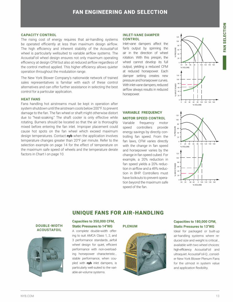
CAPACITY CONTROL The rising cost of energy requires that air-handling systems be operated efficiently at less than maximum design airflow. The high efficiency and inherent stability of the AcoustaFoil wheel is particularly wellsuited to variable airflow systems. The AcoustaFoil wheel design ensures not only maximum operating efficiency at design CFM but also at reduced airflow regardless of the control method applied. This higher efficiency allows quieter operation throughout the modulation range.
The New York Blower Company’s nationwide network of trained sales representatives is familiar with each of these control alternatives and can offer further assistance in selecting the best control for a particular application.
HEAT FANS Fans handling hot airstreams must be kept in operation after system shutdown until the airstream cools below 200°F. to prevent damage to the fan. The fan wheel or shaft might otherwise distort due to “heat-soaking.” The shaft cooler is only effective while rotating. Burners should be located so that the air is thoroughly mixed before entering the fan inlet. Improper placement could cause hot spots on the fan wheel which exceed maximum design temperatures. Contact nyb when the application involves temperature changes greater than 20°F per minute. Refer to the selection example on page 14 for the effect of temperature on the maximum safe speed of wheels and the temperature derate factors in Chart I on page 10.
INLET-VANE DAMPER CONTROLInlet-vane dampers affect the fan’s output by spinning the air in the direction of wheel rotation. With this prespin, the wheel cannot develop its full output, yielding a reduced CFM at reduced horsepower. Each damper setting creates new pressure and horsepower curves. With inlet-vane dampers, reduced airflow always results in reduced horsepower.
VARIABLE FREQUENCY
MOTOR SPEED CONTROLVariable frequency motor speed controllers provide energy savings by directly con-trolling fan speed. From the fan laws, CFM varies directly with the change in fan speed and horsepower varies by the change in fan speed cubed. For example, a 20% reduction in fan speed yields a 20% reduc-tion in airflow and a 49% reduc-tion in BHP. Controllers must have lockouts to prevent opera-tion beyond the maximum safe speed of the fan.
20
0
40
60
80
100
120
02 04 06 08 0 100 120 140 160
% P
RESS
URE
% VOLUME
100806040200
% VOLUME160140120
80
60
20
0
40
120
100
% IN
PUT
POW
ER%
PRE
SSU
RE
80
60
20
0
40
120
100
100806040200 160140120
% VOLUME
% IN
PUT
POW
ER
40
60
80
100
120
20
0
% VOLUME1002004 08 060 160140120
FAN ENGINEERING AND SELECTION
UNIQUE FANS FOR AIR-HANDLING
DOUBLE-WIDTH ACOUSTAFOIL
Capacities to 180,000 CFM, Static Pressures to 13″WGIdeal for packaged or built-up air-handling systems where re-duced size and weight is critical…available with two wheel choices: high-efficiency AcoustaFoil and ultraquiet AcoustaFoil-Q…consid-er New York Blower Plenum Fans for the utmost in system value and application flexibility.
PLENUMCapacities to 350,000 CFM, Static Pressures to 14″WGA complete double-width offer-ing to suit AMCA Class 1, 2, and 3 performance standards…airfoil wheel design for quiet, efficient performance with non-overload-ing horsepower characteristic…stable performance, when cou-pled with nyb inlet dampers, is particularly well-suited to the vari-able-air-volume systems.

14 NEW YORK BLOWER | SINGLE-WIDTH FANS
PER
FOR
MA
NC
E
PERFORMANCEHOW TO USE PERFORMANCE TABLES
For a given fan size, wheel design, CFM, and static pressure, performance tables can be used to obtain outlet velocity, fan RPM, and BHP. If capacities are at conditions other 70°F., sea level, or standard density [.075 lb./cu.ft.], correction factors must be applied to static pressure and BHP.
Procedures Steps EXAMPLE: A fan is required for 13,000 CFM at 4”WG at 600°F. and sea level.
If conditions other than standard are involved, correct static pressure for actual altitude and temperature using Charts II and III.
1Chart II gives a 2.00 factor for 600°F. Corrected SP is 4″WG x 2.00 = 8″WG at 70°F. Select fan from performance tables for 13,000 CFM at 8”WG.
Select size, wheel type, RPM, and BHP of fan from performance table.
2A Size 30 with AcoustaFoil wheel is selected for 13,000 CFM at 8″WG at 1650 RPM and 20.5 BHP.
Check maximum safe speed of fan at operating temperature as shown in the performance tables and Chart I.
3From the performance table and Chart I, the maximum safe speed of a Size 30 fan with Class 2 AcoustaFoil wheel at 600°F. is 1660 RPM [1805 x .92]. Fan is satisfactory for operation at 600°F.
Determine actual performance at operating conditions by correcting SP and BHP.
4Actual performance: 13,000 CFM at 4”WG [8” ÷ 2.00] at 1650 RPM at 10.3 BHP [20.5 ÷ 2] at 600°F.
PERFORMANCE CORRECTION FACTORSFan performance is based on actual feet per minute [ACFM] at the fan inlet at standard density [.075 lbs./ft.3] and static pressure at the fan outlet. Static pressure capabilities are shown in inches water gauge [“WG].
Air-density corrections are necessary for proper selection when air density varies from the standard .075 lbs./ft.3 at 70°F. at sea level. Multiply the required static pressure at operating conditions by the appropriate factors in Charts II and III to obtain the corrected static pressure for standard conditions. Pressure and BHP will be reduced at conditions by the inverse of these factors. Multiply one factor by the other if temperature and altitude are non-standard. For example: if the installation is located at an altitude of 4000 feet and the gas temperature is 300°F. the correction factor is 1.66 [1.16 x 1.43]. Temperature and altitude correction is made automatically using nyb's online fan size program available at www.nyb.com.
MAXIMUM SAFE SPEED INFORMATIONEach performance table on pages 16-24 includes the maximum safe speed of the standard wheel at 70°F. Fan operation at temperatures above 70°F. primarily affects the strength of rotating components, which declines as temperature increases. When alloy construction is specified or when temperatures are involved, multiply the appropriate safe operating speed shown in the performance table by the factor shown in Chart 1 on page 15. Note that Sizes 12 and 15 AcoustaFoil wheels are aluminum as standard. Also that the maximum safe speeds apply only to wheels operated at or below 70°F. and are free of material build-up, corrosion, or wear. See discussion on page 12 regarding direct-drive fans and maximum safe wheel speeds for wheels that are narrow-width. Maximum wheel safe speeds are computed automatically using nyb's online fan size program available at www.nyb.com.
NEW YORK BLOWER’S MOBILE APPLICATION
A mobile app is now available for iOS and Android phones. Key benefits include:
• Ability to view and download your fan’s drawings, performance curves, and maintenance manuals.
• Connect to the online ordering platform to easily order replacement parts.• Ability to look up your local representative and save their contact
information.• Make system calculations or calculate changes in your fan’s performance.

15NYB.COM
PER
FOR
MA
NC
E
CHART I Temperature Correction Factors For Wheel Operating Speeds
Temp.°F.Wheel material
Steel Aluminum Stainless 304*
Stainless 316*
Stainless 347*
-50 1.00 1.00 1.00 1.00 1.00
70 1.00 1.00 1.00 1.00 1.00
200 .97 .98 .88 .95 .95
300 .95 — .82 .92 .93
400 .94 — .78 .89 .90
500 .93 — .75 .86 .90
600 .92 — .73 .84 .90
650 .89 — .71 .82 .90
*PLR Fans only.
CHART IIICorrection Factors For Altitude
[Feet Above Sea Level]
Alt. Factor
0 1.00
500 1.02
1000 1.04
1500 1.06
2000 1.08
2500 1.10
3000 1.12
3500 1.14
4000 1.16
4500 1.18
5000 1.20
5500 1.23
6000 1.25
7000 1.30
8000 1.35
9000 1.40
10000 1.45NOTE: When more than one correction is made, the factors are combined by multiplying factors.
CHART IITemperature Correction Factors (°F)
Temp. °F. Factor Temp.
°F. Factor
- 50 .77 250 1.34
-25 .82 275 1.39
0 .87 300 1.43
20 .91 325 1.48
40 .94 350 1.53
60 .98 375 1.58
70 1.00 400 1.62
80 1.02 450 1.72
100 1.06 500 1.81
120 1.09 550 1.91
140 1.13 600 2.00
160 1.17 650 2.10
180 1.21 750 —
200 1.25 — —
225 1.29 — —
NOTE: Please refer to our line of fans for many different material combinations and designs that may allow you to operate to 1800°F.
HEAVY-DUTY FANS FOR HIGHER PRESSURES
CLASS 4 BACKWARD INCLINED SWSI FANSCapacities to 170,000 CFM, Static Pressures to 20″WG
A heavier-duty extension of the Single-Width Fan design for higher pressure requirements…choice of two wheels for best efficiency:
AcoustaFoil for clean, dry airstreams and PLR for moderate amounts of dirt and moisture…temperatures to 750°F.
AF FANSCapacities to 130,000 CFM, 50″WG
Airfoil-wheel design for high efficiency with non-overloading horsepower characteristic featuring curves which cover a wide range of narrow-width performance at direct-drive motor speeds…well-suited to higher horsepowers required for high-pressure performance.

16 NEW YORK BLOWER | SINGLE-WIDTH FANS
AC
OU
STA
FOIL
ACOUSTAFOILPERFORMANCE FOR SINGLE-WIDTH FANS WITH ACOUSTAFOIL WHEELS
SIZE12Max. safe speeds Class 1=3755 RPMClass 2=4900 RPM
CFM OV1″SP 2″SP 3″SP 4″SP 6″SP 8″SP 10″SP 12″SP 14″SP
RPM BHP RPM BHP RPM BHP RPM BHP RPM BHP RPM BHP RPM BHP RPM BHP RPM BHP1000 1163 1714 0.53 1928 0.63 2120 0.74 2514 1.29 2895 1.29 3235 1.63 3526 1.97 3806 2.34 4066 2.771300 1512 1961 0.63 2160 0.75 2334 0.88 2642 1.15 2939 1.44 3241 1.78 3550 2.18 3837 2.61 4093 3.091600 1860 2242 0.77 2409 0.92 2574 1.07 2865 1.37 3122 1.70 3363 2.04 3607 2.41 3846 2.85 4095 3.361900 2209 2541 0.96 2689 1.12 2828 1.29 3105 1.65 3352 2.01 3571 2.39 3772 2.80 3979 3.28 4182 3.77
2100 2442 2748 1.11 2882 1.28 3013 1.47 3267 1.86 3509 2.25 3730 2.68 3923 3.14 4120 3.65 4303 4.152400 2791 3066 1.38 3189 1.58 3306 1.79 3530 2.22 3509 2.69 3972 3.20 4161 3.71 4342 4.24 4516 4.802700 3140 3391 1.73 3502 1.95 3605 2.17 3815 2.66 4012 3.22 4210 3.80 4406 4.37 4583 4.94 4749 5.523000 3488 3721 2.14 3819 2.38 3919 2.65 4109 3.23 4288 3.81 4465 4.44 4647 5.10 4823 5.73 — —
SIZE15Max. safe speeds Class 1=2910 RPMClass 2=3800 RPM
CFM OV1″SP 2″SP 3″SP 4″SP 6″SP 8″SP 10″SP 12″SP 14″SP
RPM BHP RPM BHP RPM BHP RPM BHP RPM BHP RPM BHP RPM BHP RPM BHP RPM BHP1400 1085 1350 0.60 1536 0.74 1706 0.89 2014 1.23 2286 1.60 2541 2.02 2784 2.48 3007 3.02 3210 3.581800 1395 1527 0.71 1691 0.88 1841 1.05 2115 1.43 2362 1.84 2595 2.29 2811 2.80 3028 3.40 3220 3.992200 1705 1722 0.87 1867 1.05 2002 1.25 2254 1.68 2480 2.14 2692 2.64 2888 3.20 3083 3.82 3271 4.482600 2016 1927 1.06 2059 1.28 2185 1.51 2417 1.99 2622 2.48 2823 3.09 3001 3.69 3186 4.37 3354 5.04
3000 2326 2139 1.30 2264 1.55 2380 1.81 2592 2.34 2789 2.94 2966 3.58 3140 4.25 3311 4.98 3467 5.693400 2636 2357 1.60 2471 1.88 2581 2.17 2776 2.77 2962 3.46 3138 4.19 3298 4.91 3454 5.66 3609 6.463800 2946 2581 1.97 2687 2.28 2790 2.60 2975 3.32 3148 4.06 3313 4.85 3467 5.64 3611 6.42 3759 7.284200 3256 2807 2.41 2906 2.77 3001 3.16 3176 3.94 3345 4.77 3497 5.59 3641 6.42 3785 7.31 — —
SIZE18 Max. safe speeds Class 1=2305 RPMClass 2=3005 RPMClass 3=3790 RPM
CFM OV1″SP 2″SP 3″SP 4″SP 6″SP 8″SP 10″SP 12″SP 14″SP
RPM BHP RPM BHP RPM BHP RPM BHP RPM BHP RPM BHP RPM BHP RPM BHP RPM BHP2000 1042 1028 0.69 1333 1.10 1605 1.60 1850 2.15 2287 3.56 2658 5.18 2996 6.99 3283 8.82 3562 10.92900 1510 1238 0.94 1467 1.42 1685 1.98 1888 2.61 2274 4.23 2613 6.01 2931 7.99 3225 10.1 3497 12.43800 1979 1482 1.33 1673 1.91 1850 2.54 2017 3.31 2339 5.04 2647 7.01 2937 9.17 3205 11.5 3468 13.94700 2448 1741 1.88 1910 2.60 2062 3.42 2203 4.26 2481 6.16 2744 8.23 3000 10.5 3248 13.0 3482 15.6
5600 2917 2009 2.63 2160 3.58 2293 4.52 2420 5.49 2668 7.60 2896 9.80 3123 12.2 3339 14.8 3549 17.46500 3385 2279 3.70 2421 4.86 2545 5.95 2661 7.06 2878 9.33 3088 11.8 3286 14.3 3482 17.0 3679 19.97400 3854 2554 5.06 2686 6.40 2801 7.67 2907 8.89 3106 11.4 3297 14.1 3479 16.8 3655 19.7 — —8300 4323 2833 6.75 2955 8.28 3063 7.67 3164 11.1 3351 14.0 3527 16.8 3691 19.7 — — — —
SIZE22 Max. safe speeds Class 1=1970 RPMClass 2=2570 RPMClass 3=3240 RPM
CFM OV1″SP 2″SP 3″SP 4″SP 6″SP 8″SP 10″SP 12″SP 14″SP
RPM BHP RPM BHP RPM BHP RPM BHP RPM BHP RPM BHP RPM BHP RPM BHP RPM BHP3000 1053 846 0.88 1096 1.49 1321 2.23 1524 3.15 1864 5.23 2166 7.66 2430 10.3 2672 13.2 2885 16.14300 1509 1011 1.24 1203 1.97 1383 2.84 1556 3.90 1871 6.27 2149 8.90 2430 11.8 2640 14.9 2852 18.25600 1965 1205 1.79 1364 2.68 1512 3.75 1654 4.92 1922 7.47 2173 10.3 2415 13.5 2637 16.9 2839 20.46900 2421 1413 2.57 1551 3.75 1675 4.95 1797 6.26 2029 9.08 2173 12.1 2457 15.4 2666 19.1 2863 23.0
8200 2877 1626 3.75 1750 5.13 1862 6.53 1966 7.96 2171 11.1 2362 14.3 2551 17.9 2735 21.7 2915 25.89500 3333 1842 5.27 1956 6.87 2059 8.50 2152 10.1 2337 13.5 2511 17.1 2678 20.9 2843 17.0 3000 29.0
10800 3789 2062 7.21 2168 9.05 2261 10.8 2349 12.7 2515 16.4 2671 20.2 2827 24.4 2843 28.7 3127 33.312100 4246 2284 9.60 2383 11.7 2471 13.7 2554 15.8 2705 19.8 2852 24.1 2990 28.4 3126 32.9 — —
SIZE24 Max. safe speeds Class 1=1970 RPMClass 2=2335 RPMClass 3=3940 RPM
CFM OV1″SP 2″SP 3″SP 4″SP 6″SP 8″SP 10″SP 12″SP 14″SP
RPM BHP RPM BHP RPM BHP RPM BHP RPM BHP RPM BHP RPM BHP RPM BHP RPM BHP3000 870 728 0.84 996 1.49 1223 2.29 1419 3.29 1747 5.64 2023 8.32 2272 11.4 2494 14.6 2690 18.05000 1449 904 1.30 1080 2.09 1254 3.08 1421 4.26 1725 6.89 1997 9.94 2241 13.3 2459 16.8 2670 20.87000 2029 1137 2.06 1269 3.14 1397 4.38 1522 5.69 1770 8.64 2007 11.9 2233 15.6 2443 19.5 2637 23.59000 2609 1386 3.30 1499 4.75 1602 6.23 1703 7.78 1898 11.0 2093 14.7 2281 18.5 2468 22.7 2644 27.0
11000 3188 1642 5.12 1743 6.92 1832 8.68 1917 10.5 2083 14.2 2242 18.2 2400 22.3 2563 26.9 2722 31.713000 3768 1903 7.57 1995 9.75 2076 11.8 2151 13.9 2296 18.2 2434 22.6 2571 27.2 2706 32.0 2845 37.215000 4348 2167 10.8 2250 13.3 2327 15.8 2395 18.2 2523 23.0 2649 28.0 2769 33.0 2886 38.1 — —17000 4928 2433 14.9 2510 17.8 2581 20.6 2645 23.4 2764 28.8 2879 34.4 — — — — — —
SIZE27 Max. safe speeds Class 1=1540 RPMClass 2=2010 RPMClass 3=2530 RPM
CFM OV1″SP 2″SP 3″SP 4″SP 6″SP 8″SP 10″SP 12″SP 14″SP
RPM BHP RPM BHP RPM BHP RPM BHP RPM BHP RPM BHP RPM BHP RPM BHP RPM BHP4000 955 657 0.78 990 1.70 1107 2.83 1289 4.14 1583 7.03 1837 10.4 2051 14.0 2258 18.1 2441 22.47000 1671 841 1.62 992 2.78 1139 4.08 1290 5.60 1563 8.94 1809 12.8 2024 16.9 2232 21.6 2411 26.39000 2148 1001 2.53 1122 3.93 1239 5.43 1355 7.04 1586 10.6 1805 14.7 2015 19.1 2211 24.0 2394 29.111000 2625 1173 3.82 1276 5.48 1371 7.16 1468 8.99 1659 12.9 1849 17.2 2030 21.8 2213 24.0 2388 32.4
13000 3103 1350 5.54 1440 7.49 1524 9.44 1605 11.4 1769 15.8 1932 20.5 2091 25.3 2252 30.7 2405 36.215000 3580 1530 7.77 1611 10.0 1686 12.3 1759 14.5 1899 19.2 2041 24.2 2182 29.6 2321 35.1 2461 41.017000 4057 1713 10.6 1786 13.1 1856 15.7 1920 18.2 2045 23.3 2172 28.8 2296 34.5 2421 40.5 — —19000 4535 1897 14.1 1964 16.9 2028 19.8 2088 22.6 2203 28.2 2315 34.1 2427 40.2 — — — —
Performance certified is for installation Type B: Free inlet, Ducted outlet. Power rating (BHP) does not include transmission losses. Performance ratings do not include the effects of appurtenances (accessories).

17NYB.COM
AC
OU
STA
FOIL
PERFORMANCE FOR SINGLE-WIDTH FANS WITH ACOUSTAFOIL WHEELS
SIZE30Max. safe speeds Class 1=1385 RPMClass 2=1805 RPMClass 3=2275 RPM
CFM OV1″SP 2″SP 3″SP 4″SP 6″SP 8″SP 10″SP 12″SP 14″SP
RPM BHP RPM BHP RPM BHP RPM BHP RPM BHP RPM BHP RPM BHP RPM BHP RPM BHP7000 1354 670 1.44 836 2.73 1000 4.29 1150 6.03 1416 10.0 1643 14.5 1840 19.3 2015 24.4 2182 30.19000 1741 776 2.13 907 3.60 1036 5.25 1165 7.13 1408 11.4 1628 16.2 1824 21.4 2005 27.1 2172 33.111000 2128 895 3.08 1002 4.74 1109 6.58 1215 8.58 1428 13.1 1632 18.3 1820 23.8 1995 29.8 2155 35.913000 2515 1020 4.32 1114 6.25 1203 8.25 1293 10.4 1475 15.2 1849 20.5 1824 26.3 1994 32.7 2148 39.2
15000 2901 1148 5.91 1232 8.12 1311 10.3 1391 12.8 1548 17.9 1700 23.3 1858 29.5 2011 36.1 2155 42.817000 3288 1277 7.86 1355 10.4 1426 12.9 1496 15.4 1636 21.0 1771 26.8 1912 33.3 2045 39.8 2184 47.219000 3675 1409 10.3 1481 13.1 1547 15.9 1611 18.7 1735 24.6 1858 30.9 1979 37.3 2101 44.3 2228 52.021000 4062 1542 13.2 1608 16.3 1671 19.4 1729 22.5 2203 28.7 1956 35.5 2068 42.5 2175 49.6 — —
SIZE33 Max. safe speeds Class 1=1265 RPMClass 2=1650 RPMClass 3=2080 RPM
CFM OV1″SP 2″SP 3″SP 4″SP 6″SP 8″SP 10″SP 12″SP 14″SP
RPM BHP RPM BHP RPM BHP RPM BHP RPM BHP RPM BHP RPM BHP RPM BHP RPM BHP7000 1118 563 1.38 747 2.87 905 4.62 1043 6.55 1276 10.8 1483 15.8 1662 21.2 1832 27.3 1983 33.5
10000 1597 654 2.13 800 3.96 936 6.00 1060 8.23 1280 13.1 1473 18.6 1650 24.6 1808 30.9 1960 37.913000 2077 780 3.33 886 5.38 997 7.73 1106 10.3 1305 15.8 1487 21.8 1651 28.3 1805 35.3 1953 42.816000 2556 924 5.14 1000 7.35 1086 9.90 1176 12.7 1355 19.0 1524 25.7 1678 32.8 1827 40.5 1959 48.1
19000 3035 1073 7.63 1132 10.0 1199 12.8 1176 15.9 1424 22.6 1573 29.8 1719 37.7 1855 45.9 1990 54.721000 3355 1175 9.77 1226 12.3 1284 15.2 1348 18.4 1483 25.4 1621 33.2 1757 41.4 1887 50.1 2009 58.824000 3834 1329 13.7 1374 16.6 1420 19.6 1472 23.0 1586 30.5 1704 38.6 1826 47.5 1949 57.0 2063 66.527000 4313 1484 18.7 1524 21.9 1564 25.2 1606 28.7 1702 36.6 1806 45.2 1911 54.5 2021 64.6 — —
SIZE36 Max. safe speeds Class 1=1110 RPMClass 2=1450 RPMClass 3=1825 RPM
CFM OV1″SP 2″SP 3″SP 4″SP 6″SP 8″SP 10″SP 12″SP 14″SP
RPM BHP RPM BHP RPM BHP RPM BHP RPM BHP RPM BHP RPM BHP RPM BHP RPM BHP10000 1305 539 1.97 683 3.83 819 6.02 943 8.48 1162 14.1 1348 20.3 1508 26.8 1656 34.0 1790 41.614000 1828 656 3.30 760 5.51 864 8.03 966 10.8 1158 17.0 1337 24.0 1496 31.4 1642 39.4 1770 47.918000 2350 788 5.29 871 7.93 952 10.8 1033 13.9 1193 20.7 1350 28.3 1496 36.5 1637 45.3 1767 54.522000 2872 926 8.07 999 11.3 1066 14.5 1133 18.0 1264 25.4 1393 33.4 1523 42.3 1648 51.6 1776 62.0
26000 3394 1068 11.8 1133 15.6 1192 19.4 1250 18.0 1361 31.4 1472 40.1 1582 49.4 1695 59.7 1805 70.330000 3916 1212 16.7 1271 21.1 1325 25.4 1375 29.7 1475 38.8 1570 48.1 1670 58.6 1767 69.2 — —34000 4439 1358 22.9 1412 27.9 1462 32.8 1508 37.7 1598 47.8 1683 57.9 1770 68.9 — — — —38000 4961 1505 30.6 1555 36.1 1601 41.7 1644 47.1 1727 58.3 1806 69.5 — — — — — —
SIZE40 Max. safe speeds Class 1=1110 RPMClass 2=1450 RPMClass 3=1825 RPM
CFM OV1″SP 2″SP 3″SP 4″SP 6″SP 8″SP 10″SP 12″SP 14″SP
RPM BHP RPM BHP RPM BHP RPM BHP RPM BHP RPM BHP RPM BHP RPM BHP RPM BHP12000 1289 487 2.36 618 4.59 742 7.27 857 10.3 1055 17.1 1219 24.5 1369 32.8 1500 41.3 1624 50.616000 1719 571 3.63 671 6.19 770 9.10 869 12.5 1051 19.9 1215 28.4 1369 37.2 1500 46.9 1613 57.020000 2418 667 5.43 749 8.43 828 11.7 909 15.2 1066 23.2 1217 32.3 1353 41.9 1482 52.3 1606 63.624000 2578 769 7.82 839 11.3 907 15.0 973 18.9 1105 27.3 1238 36.9 1364 47.2 1485 58.2 1604 70.3
28000 3008 873 10.9 936 15.0 994 19.1 1053 23.5 1167 32.6 1279 42.4 1395 53.5 1504 65.0 1616 77.932000 3437 980 14.7 1037 19.6 1090 24.3 1141 29.0 1241 38.8 1342 49.6 1443 61.1 1538 72.7 1638 85.736000 4439 1358 22.9 1786 13.1 1856 15.7 1920 18.2 2045 23.3 2172 28.8 2296 34.5 2421 40.5 — —40000 4961 1505 30.6 1964 16.9 2028 19.8 2088 22.6 2203 28.2 2315 34.1 2427 40.2 — — — —
SIZE44 Max. safe speeds Class 1=910 RPMClass 2=1190 RPMClass 3=1495 RPM
CFM OV1″SP 2″SP 3″SP 4″SP 6″SP 8″SP 10″SP 12″SP 14″SP
RPM BHP RPM BHP RPM BHP RPM BHP RPM BHP RPM BHP RPM BHP RPM BHP RPM BHP14000 1229 431 2.71 556 5.42 672 8.67 775 12.3 954 20.4 1104 14.5 1241 39.4 1361 49.8 1466 60.422000 1756 523 4.60 613 7.79 700 11.4 787 15.4 952 24.8 1094 34.8 1231 46.4 1351 58.3 1460 70.625000 2195 613 6.93 686 10.6 758 14.7 829 19.1 968 28.9 1099 39.8 1224 51.9 1339 64.6 1449 78.330000 2634 708 10.0 770 14.4 830 19.0 889 23.7 1005 34.1 1122 45.8 1235 58.5 1344 72.1 1450 86.9
35000 3073 805 14.0 861 19.2 913 24.3 964 29.6 1066 41.1 1166 53.2 1267 66.8 1367 81.2 1463 96.440000 3512 904 19.0 955 25.1 1002 30.9 1047 36.8 1136 49.0 1226 62.4 1314 76.4 1401 91.1 1487 10745000 3951 1005 25.2 1050 32.0 1094 38.7 1135 45.3 1216 58.9 1294 72.8 1373 87.7 1451 103 — —50000 4390 1106 32.7 1149 40.5 1189 48.1 1227 55.5 1299 69.9 1372 85.2 1443 101 — — — —
SIZE49 Max. safe speeds Class 1=850 RPMClass 2=1105 RPMClass 3=1395 RPM
CFM OV1″SP 2″SP 3″SP 4″SP 6″SP 8″SP 10″SP 12″SP 14″SP
RPM BHP RPM BHP RPM BHP RPM BHP RPM BHP RPM BHP RPM BHP RPM BHP RPM BHP17000 1232 392 3.30 505 6.57 611 10.5 705 15.0 865 24.7 1002 35.5 1126 47.6 1235 60.4 1332 73.224000 1739 472 5.46 554 9.34 635 13.7 715 18.7 862 29.7 998 42.4 1115 55.5 1226 70.1 1326 85.230000 2174 553 8.23 619 12.7 684 17.5 749 22.9 875 34.5 1000 48.2 1113 62.7 1220 78.4 1316 94.336000 2609 638 11.9 695 17.2 749 22.6 803 28.3 913 41.2 1019 55.2 1121 70.4 1222 87.2 1316 104
42000 3043 725 16.6 776 22.8 823 28.9 871 35.5 962 48.9 1054 63.6 1148 80.2 1237 97.1 1326 11648000 3478 814 22.5 860 29.7 903 36.8 945 43.9 1027 58.7 1107 74.5 1190 91.6 1270 110 1350 12954000 3913 904 29.7 946 38.1 985 46.0 1023 54.0 1096 70.0 1169 86.9 1242 105 1315 124 1358 14460000 4348 995 38.6 1034 47.9 1071 57.1 1105 65.8 1173 83.6 1238 102 1304 121 1369 141 — —
Performance certified is for installation Type B: Free inlet, Ducted outlet. Power rating (BHP) does not include transmission losses. Performance ratings do not include the effects of appurtenances (accessories).

18 NEW YORK BLOWER | SINGLE-WIDTH FANS
AC
OU
STA
FOIL
PERFORMANCE FOR SINGLE-WIDTH FANS WITH ACOUSTAFOIL WHEELS
SIZE54Max. safe speeds Class 1=750 RPMClass 2=975 RPMClass 3=1230 RPM
CFM OV1″SP 1½″SP 2″SP 3″SP 4″SP 5″SP 6″SP 7″SP 8″SP
RPM BHP RPM BHP RPM BHP RPM BHP RPM BHP RPM BHP RPM BHP RPM BHP RPM BHP20000 1182 349 3.86 454 7.81 552 12.6 636 17.8 783 29.7 908 43.0 1019 57.6 1114 72.3 1205 88.630000 1773 432 6.95 504 11.7 575 17.1 647 23.2 779 36.8 900 52.3 1009 69.1 1108 87.0 1198 10540000 2364 532 11.9 588 17.8 642 24.0 697 30.8 804 45.8 908 62.5 1005 80.6 1099 100 1189 12150000 2955 639 19.1 686 26.4 730 33.8 774 41.6 860 58.0 945 75.8 1030 95.4 1112 116 1196 139
60000 3546 748 28.8 789 37.9 827 46.7 864 55.5 937 74.1 1009 93.6 1081 115 1154 137 1223 16065000 3842 803 34.8 842 44.9 879 54.6 913 64.0 980 83.6 1047 104 1112 125 1179 149 — —70000 4137 859 41.8 896 52.7 930 63.2 962 73.3 1026 94.2 1088 116 1149 138 1212 162 — —75000 4433 915 49.7 949 61.3 982 72.7 1013 83.7 1073 106 1131 129 1190 152 — — — —
SIZE60 Max. safe speeds Class 1=675 RPMClass 2=880 RPMClass 3=1110 RPM
CFM OV1″SP 1½″SP 2″SP 3″SP 4″SP 5″SP 6″SP 7″SP 8″SP
RPM BHP RPM BHP RPM BHP RPM BHP RPM BHP RPM BHP RPM BHP RPM BHP RPM BHP25000 1280 318 4.85 411 9.68 497 15.5 574 22.0 707 36.8 821 53.1 918 70.6 1011 90.2 1092 11035000 1691 379 7.84 447 13.5 514 19.9 581 27.3 703 43.7 815 62.6 910 81.9 1002 104 1085 12645000 2174 451 12.3 506 19.1 559 26.3 611 34.2 715 51.9 816 72.2 909 94.1 994 117 1079 14355000 2657 529 18.5 574 26.5 618 34.8 661 43.5 749 62.8 836 84.4 916 107 999 132 1076 159
65000 3140 608 26.7 649 36.4 687 45.9 724 55.7 798 76.7 870 98.8 945 124 1017 150 1086 17775000 3623 689 37.1 726 48.6 760 59.6 793 70.7 856 93.2 922 118 985 144 1048 171 — —85000 4106 772 50.3 805 63.3 836 76.1 865 88.3 922 113 979 140 1035 167 1093 197 — —95000 4589 854 66.4 885 81.3 914 95.8 941 110 993 138 1044 166 1095 196 — — — —
SIZE66 Max. safe speeds Class 1= 615 RPMClass 2=800 RPMClass 3=1010 RPM
CFM OV1″SP 2″SP 3″SP 4″SP 6″SP 8″SP 10″SP 12″SP 14″SP
RPM BHP RPM BHP RPM BHP RPM BHP RPM BHP RPM BHP RPM BHP RPM BHP RPM BHP30000 1198 288 5.81 374 11.7 453 18.8 523 26.7 643 44.3 745 63.9 835 85.1 916 108 990 13242000 1677 343 9.39 405 16.2 468 24.1 529 33.0 639 52.5 738 74.6 830 99.3 912 125 985 15254000 2156 408 14.7 457 22.7 507 31.6 555 41.1 651 62.7 741 86.9 828 114 906 142 980 17166000 2635 477 22.0 519 31.7 559 41.5 600 52.4 679 75.2 759 101 833 129 909 160 977 191
78000 3114 549 31.7 586 43.4 621 54.7 655 66.5 723 91.8 789 119 855 148 922 180 985 21390000 3593 622 44.0 655 57.6 687 71.1 717 84.4 775 112 833 141 894 173 950 205 1007 239
102000 4072 696 59.6 727 75.4 755 90.7 782 105 835 136 887 167 939 201 990 235 — —114000 4551 771 78.8 799 96.5 825 114 850 131 898 164 945 198 991 234 — — — —
SIZE73 Max. safe speeds Class 1= 555 RPMClass 2=725 RPMClass 3=915 RPM
CFM OV1″SP 2″SP 3″SP 4″SP 6″SP 8″SP 10″SP 12″SP 14″SP
RPM BHP RPM BHP RPM BHP RPM BHP RPM BHP RPM BHP RPM BHP RPM BHP RPM BHP
40000 1305 270 7.89 341 15.3 409 24.1 474 34.4 580 56.5 671 80.9 755 109 828 137 893 16655000 1795 324 12.8 377 21.5 429 31.2 481 42.2 580 67.4 670 95.7 750 126 824 159 890 19270000 2285 386 20.2 428 30.5 470 41.7 512 53.7 594 80.6 672 110 748 144 818 178 884 21685000 2774 450 30.0 487 42.6 522 55.3 555 68.4 624 97.4 693 130 757 164 823 202 887 243
100000 3264 517 43.1 549 58.2 579 72.7 609 87.9 668 120 725 153 784 191 840 229 896 270115000 3753 585 59.7 614 77.1 641 94.3 667 111 719 146 768 182 820 222 870 263 — —130000 4243 653 80.7 680 101 705 120 728 139 775 178 819 217 864 259 910 303 — —145000 4732 723 107 747 129 770 151 792 173 834 215 875 258 — — — — — —
SIZE80 Max. safe speeds Class 1=500 RPMClass 2=650 RPMClass 3=825 RPM
CFM OV1″SP 2″SP 3″SP 4″SP 6″SP 8″SP 10″SP 12″SP 14″SP
RPM BHP RPM BHP RPM BHP RPM BHP RPM BHP RPM BHP RPM BHP RPM BHP RPM BHP60000 1602 272 13 326 23 379 34.5 430 47.6 522 76.6 605 110 679 145 745 183 805 22277000 2056 322 20.1 364 31.7 406 44.4 447 58.5 528 90.3 604 125 675 165 739 205 803 25294000 2510 375 29.7 410 43.5 445 57.9 479 73 547 107 613 144 679 187 740 230 798 277111000 2964 430 42.3 462 59 491 75 520 92 577 128 636 169 693 212 747 258 802 308
128000 3418 486 58.4 514 77.7 541 96.7 567 116 618 156 668 198 717 243 766 291 815 343145000 3872 543 78.7 569 101 593 122 616 144 661 187 705 233 751 282 794 332 837 384162000 4326 601 103 624 129 646 153 667 176 709 225 749 274 789 325 828 379 868 434179000 4780 659 133 680 161 701 188 721 215 759 268 795 320 831 374 868 433 — —
SIZE89 Max. safe speeds Class 1=450 RPMClass 2=590 RPMClass 3=750 RPM
CFM OV1″SP 2″SP 3″SP 4″SP 6″SP 8″SP 10″SP 12″SP 14″SP
RPM BHP RPM BHP RPM BHP RPM BHP RPM BHP RPM BHP RPM BHP RPM BHP RPM BHP75000 1652 251 16.6 299 28.8 345 42.8 391 58.8 474 94.6 550 136 617 180 675 225 731 27492000 2026 288 23.6 328 37.7 366 53 404 69.9 479 108 549 152 613 198 672 249 728 302
109000 2401 328 32.9 361 48.9 394 65.8 427 84.4 491 125 553 169 614 219 672 273 724 328126000 2775 368 44.3 398 62.9 427 81.5 455 102 511 144 568 193 622 244 675 299 726 358
143000 3150 410 58.6 437 80 463 101 488 122 538 168 587 218 637 273 685 330 731 389160000 3524 452 75.9 477 100 501 124 524 148 568 196 612 249 656 305 701 365 745 430177000 3899 495 96.6 518 124 540 150 561 176 601 228 642 285 682 343 721 404 — —194000 4273 538 121 560 151 580 181 599 208 637 266 674 325 710 386 746 451 — —
Performance certified is for installation Type B: Free inlet, Ducted outlet. Power rating (BHP) does not include transmission losses. Performance ratings do not include the effects of appurtenances (accessories).

19NYB.COM
PLR
PLRPERFORMANCE FOR SINGLE-WIDTH FANS WITH PLR WHEELS
SIZE12 Max. safe speeds Class 1=3280 RPMClass 2=4270 RPM
CFM OV1″SP 1½″SP 2″SP 3″SP 4″SP 5″SP 6″SP 7″SP 8″SP
RPM BHP RPM BHP RPM BHP RPM BHP RPM BHP RPM BHP RPM BHP RPM BHP RPM BHP1000 1170 1618 0.55 1840 0.66 2035 0.78 2382 1.05 2706 1.37 3018 1.72 3324 2.12 — — — —1300 1520 1837 0.66 2034 0.79 2212 0.93 2538 1.24 2822 1.57 3079 1.93 3327 2.31 3575 2.78 3814 3.291600 1871 2080 0.81 2255 0.96 2418 1.13 2719 1.48 2989 1.85 3230 2.23 3462 2.67 3674 3.16 3875 3.671900 2222 2340 1.01 2499 1.19 2645 1.37 2921 1.75 3167 2.16 3404 2.61 3620 3.12 3826 3.65 4026 4.22
2100 2456 2521 1.18 2666 1.37 2808 1.57 3066 1.98 3309 2.42 3529 2.92 3734 3.45 3938 4.03 4128 4.602400 2807 2802 1.48 2930 1.69 3058 1.92 3300 2.38 3523 2.89 3728 3.44 3930 4.04 4125 4.66 — —2700 3158 3089 1.85 3205 2.09 3320 2.33 3544 2.89 3749 3.46 3952 4.08 4141 4.71 — — — —3000 3509 3382 2.30 3488 2.57 3594 2.88 3797 3.50 3991 4.14 4186 4.82 — — — — — —
SIZE15 Max. safe speeds Class 1=2580 RPMClass 2=3360 RPM
CFM OV1″SP 1½″SP 2″SP 3″SP 4″SP 5″SP 6″SP 7″SP 8″SP
RPM BHP RPM BHP RPM BHP RPM BHP RPM BHP RPM BHP RPM BHP RPM BHP RPM BHP1400 1085 1285 0.64 1472 0.81 1634 0.98 1924 1.38 2200 1.84 2475 2.39 — — — — — —1800 1395 1440 0.78 1606 0.97 1755 1.17 2028 1.61 2265 2.09 2484 2.63 2705 3.31 2914 4.02 3128 4.822200 1705 1610 0.96 1762 1.18 1900 1.40 2149 1.89 2380 2.43 2582 3.05 2774 3.74 2954 4.45 3135 5.242600 2016 1792 1.19 1931 1.44 2055 1.69 2291 2.24 2499 2.85 2697 3.55 2880 4.28 3053 5.04 3216 5.85
3000 2326 1984 1.49 2109 1.77 2227 2.05 2446 2.67 2645 3.39 2826 4.13 3004 4.93 3173 5.77 3326 6.593400 2636 2186 1.86 2296 2.16 2404 2.48 2607 3.21 2799 4.00 2972 4.81 3136 5.64 3296 6.53 — —3800 2946 2393 2.30 2494 2.66 2404 3.06 2782 3.87 2960 4.71 3123 5.56 3287 6.50 — — — —4200 3256 2603 2.89 2694 3.30 2785 3.73 2965 4.64 3131 5.54 3290 6.47 — — — — — —
SIZE22 Max. safe speeds Class 1=1770 RPMClass 2=2305 RPMClass 3=2900 RPM
CFM OV1″SP 2″SP 3″SP 4″SP 6″SP 8″SP 10″SP 12″SP 14″SP
RPM BHP RPM BHP RPM BHP RPM BHP RPM BHP RPM BHP RPM BHP RPM BHP RPM BHP3000 1053 794 0.88 1066 1.63 1300 26.4 1505 4.00 — — — — — — — — — —4300 1509 920 1.21 1126 1.96 1325 2.98 1511 4.30 1839 7.48 — — — — — — — —5600 1965 1085 1.74 1249 2.58 1405 3.67 1559 4.95 1854 8.05 2124 11.8 2377 16.2 2607 21.0 — —6900 2421 1265 2.51 1402 3.60 1534 4.79 1659 6.06 1916 9.19 2155 12.8 2393 17.1 2610 21.9 2811 26.9
8200 2877 1453 3.70 1574 4.97 1685 6.26 1794 7.64 2012 10.8 2226 14.4 2434 18.6 2635 23.2 2825 28.29500 2877 1643 5.23 1754 6.73 1856 8.21 1949 9.68 2137 12.9 2328 16.7 2507 20.7 2688 25.3 2866 30.3
10800 3789 1835 7.15 1940 8.92 2030 10.5 2118 12.2 2288 15.8 2450 19.5 2615 23.7 2779 28.3 — —12100 4246 2030 9.52 2127 11.5 2214 13.5 2294 15.3 2448 19.1 2595 23.1 2746 27.5 2893 32.1 — —
SIZE18 Max. safe speeds Class 1=2100 RPMClass 2=2735 RPMClass 3=3525 RPM
CFM OV1″SP 2″SP 3″SP 4″SP 6″SP 8″SP 10″SP 12″SP 14″SP
RPM BHP RPM BHP RPM BHP RPM BHP RPM BHP RPM BHP RPM BHP RPM BHP RPM BHP2000 1042 926 0.69 1255 1.13 1548 1.69 1794 2.32 — — — — — — — — — —2900 1510 1087 0.93 1317 1.41 1545 2.00 1778 2.72 — — — — — — — — — —3800 1979 1281 1.30 1476 1.89 1653 2.52 1824 3.31 2179 5.21 2516 7.35 — — — — — —4700 2448 1495 1.83 1663 2.54 1820 3.40 1964 4.26 2245 6.18 2526 8.41 2811 10.9 — — — —
5600 2917 1716 2.54 1863 3.47 2003 4.46 2132 5.45 2379 7.56 2613 9.82 2843 12.3 3082 15.1 3322 18.16500 3385 1944 3.60 2077 4.67 2201 5.77 2320 6.92 2546 9.30 2749 11.7 2947 14.2 3153 17.0 3355 20.17400 3854 2177 4.97 2298 6.18 2410 7.40 2518 8.67 2721 11.3 2916 14.0 3099 16.7 3272 19.5 3450 22.68300 4323 2411 6.66 2524 8.01 2629 9.40 2727 10.8 2916 13.7 3097 16.7 3268 19.7 3434 22.8 — —
SIZE24 Max. safe speeds Class 1=1605 RPMClass 2=2090 RPMClass 3=2635 RPM
CFM OV1″SP 2″SP 3″SP 4″SP 6″SP 8″SP 10″SP 12″SP 14″SP
RPM BHP RPM BHP RPM BHP RPM BHP RPM BHP RPM BHP RPM BHP RPM BHP RPM BHP3000 870 694 0.91 964 1.81 1190 3.09 — — — — — — — — — — — —5000 1449 820 1.34 1009 2.22 1194 3.49 1367 5.07 1677 8.94 — — — — — — — —7000 2029 1008 2.16 1152 3.27 1290 4.59 1426 6.14 1688 9.83 1930 14.2 2155 19.3 2371 25.2 — —9000 2609 1217 3.59 1335 4.97 1447 6.46 1558 8.11 1767 11.7 1975 16.1 2180 21.2 2373 26.8 2553 32.8
11000 3188 1433 5.67 1538 7.40 1634 9.12 1725 10.9 1904 14.8 2079 19.2 2253 24.2 2424 29.7 2583 35.513000 3768 1654 8.50 1750 10.6 1835 12.7 1916 14.7 2069 18.9 2223 23.6 2370 28.5 2515 33.9 — —15000 4348 1878 12.2 1967 14.8 2045 17.1 2118 19.4 2256 24.1 2388 29.0 2521 34.4 — — — —17000 4928 2104 16.9 2186 19.9 2260 22.7 2326 25.3 2453 30.5 2574 35.9 — — — — — —
SIZE27 Max. safe speeds Class 1=1420 RPMClass 2=1850 RPMClass 3=2325 RPM
CFM OV1″SP 2″SP 3″SP 4″SP 6″SP 8″SP 10″SP 12″SP 14″SP
RPM BHP RPM BHP RPM BHP RPM BHP RPM BHP RPM BHP RPM BHP RPM BHP RPM BHP4000 955 623 1.06 862 2.00 1056 3.26 1222 4.80 — — — — — — — — — —7000 1671 761 1.85 925 3.05 1056 4.53 1228 6.22 1493 10.1 1721 14.5 1924 19.4 — — — —9000 2148 891 2.77 1021 4.26 1149 5.91 1274 7.74 1510 11.8 1728 16.5 1929 21.7 2107 27.2 2274 33.111000 2625 1033 4.20 1143 5.94 1251 7.81 1353 9.76 1558 14.1 1753 19.0 1941 24.5 2114 30.2 2282 36.6
13000 3103 1179 6.10 1278 8.15 1370 10.2 1460 12.4 1636 17.1 1809 22.3 1975 27.9 2141 34.0 2296 40.515000 3580 1330 8.58 1420 11.0 1504 13.4 1581 15.8 1737 20.9 1890 26.4 2040 32.3 2186 38.6 — —17000 4057 1483 11.7 1566 14.5 1641 17.1 1713 19.8 1852 25.4 1987 31.2 2122 37.5 2256 44.1 — —19000 4535 1637 15.5 1714 18.6 1785 21.7 1850 24.6 1979 30.8 2102 37.2 2223 43.8 — — — —
Performance certified is for installation Type B: Free inlet, Ducted outlet. Power rating (BHP) does not include transmission losses. Performance ratings do not include the effects of appurtenances (accessories).

20 NEW YORK BLOWER | SINGLE-WIDTH FANS
PLR
PERFORMANCE FOR SINGLE-WIDTH FANS WITH PLR WHEELS
SIZE30 Max. safe speeds Class 1=1280 RPMClass 2=1665 RPMClass 3=2095 RPM
CFM OV1″SP 2″SP 3″SP 4″SP 6″SP 8″SP 10″SP 12″SP 14″SP
RPM BHP RPM BHP RPM BHP RPM BHP RPM BHP RPM BHP RPM BHP RPM BHP RPM BHP7000 1354 617 1.57 793 3.05 953 4.84 1098 6.94 – – – – – – – – – –9000 1741 701 2.31 842 3.94 978 5.82 1110 8.03 1347 13.1 1553 18.9 – – – – – –11000 2128 796 3.33 914 5.15 1031 7.22 1143 9.47 1360 14.7 1554 20.6 1739 27.5 – – – –13000 2515 900 4.71 1003 6.78 1102 9.01 1200 11.4 1389 16.8 1569 22.9 1742 29.8 1909 37.5 2054 45.3
15000 2901 1007 6.46 1099 8.79 1185 11.2 1272 13.8 1440 19.5 1602 25.8 1764 32.9 1920 40.8 2059 48.617000 3288 1116 8.65 1200 11.3 1279 14.0 1356 16.8 1506 22.8 1652 29.4 1798 36.6 1937 44.3 2077 52.819000 3675 1226 11.3 1305 14.3 1378 17.3 1447 20.3 1583 26.8 1715 33.6 1847 41.1 1979 49.2 – –21000 4062 1337 14.5 1413 17.9 1479 21.1 1543 24.4 1666 31.2 1790 38.6 1912 46.4 2031 54.7 – –
SIZE33 Max. safe speeds Class 1=1175 RPMClass 2=1515 RPMClass 3=1905 RPM
CFM OV1″SP 2″SP 3″SP 4″SP 6″SP 8″SP 10″SP 12″SP 14″SP
RPM BHP RPM BHP RPM BHP RPM BHP RPM BHP RPM BHP RPM BHP RPM BHP RPM BHP7000 1118 527 1.49 709 3.19 862 5.26 996 7.69 – – – – – – – – – –
10000 1597 607 2.47 747 4.28 881 6.51 1003 9.07 1223 15.1 – – – – – – – –13000 2077 711 3.99 823 6.09 930 8.41 1036 11.1 1234 17.3 1410 24.3 1576 32.4 1730 41.3 1865 50.316000 2556 827 6.14 920 8.65 1010 11.3 1099 14.1 1270 20.5 1433 27.8 1589 36.2 1732 45.1 1870 55.0
19000 3035 948 9.00 1029 12.0 1106 15.0 1182 18.1 1331 24.9 1475 32.4 1614 40.7 1745 49.6 1878 59.921000 3355 1030 11.3 1105 14.8 1177 18.1 1245 21.4 1381 28.4 1514 36.2 1647 44.9 1767 53.7 1894 64.024000 3834 1156 15.6 1224 19.8 1287 23.6 1350 27.3 1469 34.9 1588 43.2 1703 51.9 1817 61.2 – –27000 4313 1283 20.9 1345 25.7 1404 30.2 1460 34.4 1568 42.8 1675 51.6 1781 60.9 1882 70.5 – –
SIZE40 Max. safe speeds Class 1=950 RPMClass 2=1235 RPMClass 3=1555 RPM
CFM OV1″SP 2″SP 3″SP 4″SP 6″SP 8″SP 10″SP 12″SP 14″SP
RPM BHP RPM BHP RPM BHP RPM BHP RPM BHP RPM BHP RPM BHP RPM BHP RPM BHP12000 1289 450 2.50 587 5.05 711 8.18 820 11.8 – – – – – – – – – –16000 1719 519 3.81 623 6.58 725 9.86 824 13.6 1005 22.5 1160 32.6 – – – – – –20000 2148 601 5.68 684 8.82 769 12.4 851 16.3 1011 25.4 1163 36.2 1295 47.5 1424 60.7 – –24000 2578 690 8.26 761 11.9 830 15.7 900 20.0 1039 29.5 1172 40.2 1303 52.5 1419 65.2 – –
28000 3008 781 11.6 844 15.8 905 20.1 964 24.6 1081 34.5 1200 45.7 1318 58.2 1427 71.1 1538 85.832000 3437 875 15.8 932 20.6 985 25.4 1038 30.4 1140 40.9 1246 52.7 1350 65.4 1451 78.9 1554 93.936000 3867 969 21.0 1021 26.5 1071 31.9 1117 37.2 1212 48.9 1303 60.9 1394 73.9 1487 88.1 – –40000 4296 1065 27.3 1113 33.4 1158 39.5 1203 45.6 1286 57.7 1370 70.8 1452 84.3 1537 99.1 – –
SIZE36 Max. safe speeds Class 1=1045 RPMClass 2=1360 RPMClass 3=1715 RPM
CFM OV1″SP 2″SP 3″SP 4″SP 6″SP 8″SP 10″SP 12″SP 14″SP
RPM BHP RPM BHP RPM BHP RPM BHP RPM BHP RPM BHP RPM BHP RPM BHP RPM BHP10000 1305 503 2.16 658 4.45 797 7.26 915 10.4 1119 17.7 1290 26.1 1445 35.8 1581 45.9 1704 56.714000 1828 595 3.51 709 6.05 821 9.02 930 12.5 1127 20.4 1297 29.5 1444 39.2 1582 50.0 1714 62.118000 2350 707 5.59 797 8.55 885 11.8 974 15.5 1145 23.8 1308 33.4 1454 43.9 1585 54.9 – –22000 2872 828 8.56 902 12.0 973 15.6 1047 19.6 1192 28.3 1333 38.1 1471 49.2 1599 61.0 – –
26000 3394 952 12.5 1016 16.5 1078 20.6 1139 24.9 1263 34.3 1384 44.5 1505 55.8 1624 68.2 – –30000 3916 1080 17.8 1136 22.3 1190 26.9 1244 31.7 1352 41.9 1458 52.7 1562 64.3 1669 77.1 – –34000 4439 1209 24.4 1260 29.5 1309 34.7 1357 40.0 1450 50.8 1544 62.5 1637 74.7 – – – –38000 4961 1340 32.7 1386 38.4 1430 44.2 1473 49.9 1559 61.9 1644 74.4 – – – – – –
SIZE44 Max. safe speeds Class 1=880 RPMClass 2=1120 RPMClass 3=1410 RPM
CFM OV1″SP 2″SP 3″SP 4″SP 6″SP 8″SP 10″SP 12″SP 14″SP
RPM BHP RPM BHP RPM BHP RPM BHP RPM BHP RPM BHP RPM BHP RPM BHP RPM BHP14000 1229 400 2.90 527 5.95 641 9.75 742 14.2 – – – – – – – – – –20000 1756 476 4.87 568 8.34 659 12.3 747 17.0 907 27.7 1049 40.2 – – – – – –25000 1756 552 7.34 626 11.2 701 15.7 775 20.6 915 31.5 1050 44.6 1171 58.8 1286 74.7 – –30000 2634 634 10.7 698 15.3 759 20.1 821 25.3 942 36.8 1063 50.2 1176 64.7 1289 81.6 1389 98.6
35000 3073 720 15.1 775 20.3 829 25.7 881 31.3 985 43.5 1092 57.5 1195 72.5 1296 89.2 1396 10740000 3512 806 20.6 857 26.7 905 32.8 951 39.0 1043 52.1 1134 66.1 1227 82.1 1318 98.9 1406 11745000 3951 894 27.5 941 34.3 984 41.1 1027 48.1 1107 61.9 1190 77.3 1270 93.1 1355 111 – –50000 4390 983 35.9 1026 43.6 1066 51.1 1105 58.7 1179 73.8 1253 90.0 1328 107 1399 125 – –
SIZE49 Max. safe speeds Class 1=780 RPMClass 2=1020 RPMClass 3=1280 RPM
CFM OV1″SP 2″SP 3″SP 4″SP 6″SP 8″SP 10″SP 12″SP 14″SP
RPM BHP RPM BHP RPM BHP RPM BHP RPM BHP RPM BHP RPM BHP RPM BHP RPM BHP17000 1232 363 3.52 479 7.22 584 11.9 676 17.3 – – – – – – – – – –24000 1739 429 5.78 514 9.97 598 14.9 679 20.6 826 33.7 – – – – – – – –30000 2174 498 8.73 566 13.5 634 18.8 701 24.6 831 38.0 953 53.7 1066 71.3 1167 90.0 – –36000 2609 572 12.7 630 18.2 686 24.0 742 30.1 855 44.4 962 60.1 1071 78.7 1168 97.9 1261 119
42000 3043 648 17.8 699 24.1 748 30.7 796 37.4 893 52.4 990 69.1 1083 87.0 1177 108 1266 12948000 3478 726 24.4 772 31.6 816 39.0 858 46.3 942 62.1 1026 79.3 1111 98.2 1195 119 1277 14154000 3913 805 32.5 848 40.8 887 48.9 925 56.9 1001 74.3 1076 92.5 1151 112 1227 133 – –60000 4348 885 42.4 924 51.6 961 60.7 996 69.7 1065 88.3 1132 107 1199 128 1268 150 – –
Performance certified is for installation Type B: Free inlet, Ducted outlet. Power rating (BHP) does not include transmission losses. Performance ratings do not include the effects of appurtenances (accessories).

21NYB.COM
PLR
PERFORMANCE FOR SINGLE-WIDTH FANS WITH PLR WHEELS
SIZE54 Max. safe speeds Class 1=710 RPMClass 2=920 RPMClass 3=1175 RPM
CFM OV1″SP 2″SP 3″SP 4″SP 6″SP 8″SP 10″SP 12″SP 14″SP
RPM BHP RPM BHP RPM BHP RPM BHP RPM BHP RPM BHP RPM BHP RPM BHP RPM BHP20000 1182 324 4.13 432 8.64 526 14.2 610 20.9 – – – – – – – – – –30000 1773 392 7.33 467 12.5 542 18.5 612 25.3 744 41.4 862 60.3 – – – – – –40000 2364 479 12.7 535 18.8 592 25.5 648 33.0 760 50.0 863 68.9 964 91.2 1052 114 – –50000 2955 571 20.5 619 28.1 664 35.7 709 44.0 798 61.8 887 82.0 976 105 1061 129 1139 155
60000 3546 667 31.3 708 40.4 747 49.5 785 58.7 859 78.3 933 99.4 1009 123 1082 148 1156 17565000 3842 715 38.0 754 48.0 791 57.8 826 67.6 895 88.4 964 110 1032 134 1102 160 1171 18870000 4137 764 45.8 801 56.6 835 67.0 869 77.8 934 99.7 997 123 1062 147 1127 174 – –75000 4433 813 54.6 848 66.1 881 77.7 913 89.0 973 112 1034 136 1092 161 1153 188 – –
SIZE60Max. safe speeds Class 1=640 RPMClass 2=830 RPMClass 3=1045 RPM
CFM OV1″SP 2″SP 3″SP 4″SP 6″SP 8″SP 10″SP 12″SP 14″SP
RPM BHP RPM BHP RPM BHP RPM BHP RPM BHP RPM BHP RPM BHP RPM BHP RPM BHP25000 1208 295 5.17 392 10.8 477 17.7 552 25.7 – – – – – – – – – –35000 1691 345 8.30 416 14.5 486 21.8 554 30.3 673 49.5 – – – – – – – –45000 2174 407 13.1 463 20.2 518 28.1 573 37.0 679 57.1 777 80.3 871 107 – – – –55000 2657 474 19.8 520 28.1 566 37.0 610 46.4 701 67.6 789 91.7 875 119 954 148 1030 180
65000 3140 543 28.8 585 38.7 622 48.4 661 58.8 738 81.6 813 106 889 134 962 164 1034 19775000 3623 614 40.4 651 51.9 686 63.1 719 74.5 785 98.7 852 126 917 154 984 185 – –85000 4106 686 55.0 720 68.1 752 81.1 781 93.7 840 120 900 149 957 178 1017 211 – –95000 4589 759 73.1 790 87.8 819 102 847 117 900 146 953 176 1005 207 – – – –
SIZE73 Max. safe speeds Class 1=530 RPMClass 2=685 RPMClass 3=880 RPM
CFM OV1″SP 2″SP 3″SP 4″SP 6″SP 8″SP 10″SP 12″SP 14″SP
RPM BHP RPM BHP RPM BHP RPM BHP RPM BHP RPM BHP RPM BHP RPM BHP RPM BHP40000 1305 250 8.43 324 16.8 393 27.3 453 39.3 – – – – – – – – – –55000 1795 294 13.6 349 23.0 403 33.9 457 46.7 553 75.4 640 109 – – – – – –70000 2285 347 21.3 390 32.2 434 44.3 477 57.5 560 87.5 642 123 715 162 784 204 – –85000 2774 403 32.2 440 45.0 476 58.3 512 73.1 582 104 652 140 720 181 785 224 848 273
100000 3264 461 46.5 494 61.7 524 76.7 555 92.6 615 126 676 164 737 206 796 251 853 299115000 3753 521 65.2 550 82.7 578 100 604 117 657 154 709 194 762 237 816 284 867 332130000 4243 581 88.5 608 108 633 128 657 148 704 188 751 230 798 276 842 322 – –145000 4732 642 117 666 140 689 162 712 184 755 228 797 273 838 320 879 370 – –
SIZE66 Max. safe speeds Class 1=585 RPMClass 2=755 RPMClass 3=950 RPM
CFM OV1″SP 2″SP 3″SP 4″SP 6″SP 8″SP 10″SP 12″SP 14″SP
RPM BHP RPM BHP RPM BHP RPM BHP RPM BHP RPM BHP RPM BHP RPM BHP RPM BHP30000 1198 267 6.18 355 12.9 434 21.4 502 31.1 – – – – – – – – – –42000 1677 312 9.88 377 17.3 440 26.0 503 36.4 613 60.1 – – – – – – – –54000 2156 368 15.6 419 24.2 468 33.5 520 44.3 618 68.9 707 96.9 792 129 – – – –66000 2635 428 23.5 470 33.5 513 44.3 554 55.8 636 81.2 716 110 794 143 869 179 938 218
78000 3114 490 34.1 528 45.8 563 57.7 599 70.6 669 97.7 739 128 807 161 874 198 939 23790000 3593 554 47.8 588 61.7 619 74.9 650 89.0 712 119 771 128 832 184 892 222 – –
102000 4072 620 65.3 650 80.7 678 96.1 706 111 760 143 814 178 866 213 920 252 – –114000 4551 685 86.8 713 104 739 121 765 139 814 173 861 209 910 248 – – – –
SIZE80 Max. safe speeds Class 1=475 RPMClass 2=615RPMClass 3=780 RPM
CFM OV1″SP 2″SP 3″SP 4″SP 6″SP 8″SP 10″SP 12″SP 14″SP
RPM BHP RPM BHP RPM BHP RPM BHP RPM BHP RPM BHP RPM BHP RPM BHP RPM BHP65000 1736 260 15.7 312 27 362 40.1 412 55.7 502 91.7 578 132 650 179 713 229 771 28278000 2083 293 21.8 336 34.2 379 48.3 421 63.9 504 101 578 143 645 189 711 243 768 29791000 2430 328 29.6 365 43.5 402 58.6 439 75.4 511 112 581 156 646 203 707 256 766 314
104000 2777 364 39.4 398 55.1 430 71.5 463 89.4 526 128 590 172 652 222 709 274 766 333
117000 3124 402 51.4 432 69.1 461 86.9 489 105 547 147 604 192 660 242 713 295 767 354130000 3471 439 65.7 467 85.4 494 105 520 125 571 168 622 215 674 266 725 322 774 381143000 3818 478 82.9 504 105 528 126 552 148 599 194 645 242 693 296 740 352 – –156000 4166 516 103 541 127 564 151 586 174 629 222 671 273 714 328 757 386 – –
SIZE89Max. safe speeds Class 1=430 RPMClass 2=560 RPMClass 3=705 RPM
CFM OV1″SP 2″SP 3″SP 4″SP 6″SP 8″SP 10″SP 12″SP 14″SP
RPM BHP RPM BHP RPM BHP RPM BHP RPM BHP RPM BHP RPM BHP RPM BHP RPM BHP100000 2203 276 29.4 313 45 350 62.6 386 81.7 459 127 525 178 586 235 645 301 694 365111000 2445 298 36.2 332 53.3 366 71.9 399 91.9 464 137 528 190 587 248 643 313 693 379122000 2687 321 44.3 353 62.7 383 82.1 413 103 473 150 532 203 588 262 644 329 693 395133000 2930 345 53.5 374 73.7 402 94.5 429 116 485 165 540 219 594 280 646 345 695 415
144000 3172 368 64.2 396 86.2 422 108 447 131 499 181 550 237 600 296 650 364 698 436155000 3414 392 76.3 418 99.7 443 123 466 147 514 199 561 255 608 317 656 385 701 457166000 3656 416 90.1 441 115 464 140 486 166 530 219 575 278 620 341 663 408 – –177000 3899 441 106 464 132 486 159 507 185 549 242 591 302 632 367 674 437 – –
Performance certified is for installation Type B: Free inlet, Ducted outlet. Power rating (BHP) does not include transmission losses. Performance ratings do not include the effects of appurtenances (accessories).

22 NEW YORK BLOWER | SINGLE-WIDTH FANS
BACK
WA
RD C
URVE
DBACKWARD
PERFORMANCE FOR SINGLE-WIDTH FANS WITH BC WHEELS
SIZE18 Max. safe speeds Class 1=2100 RPMClass 2=2735 RPM
CFM OV1″SP 2″SP 3″SP 4″SP 5″SP 6″SP 7″SP 8″SP 10″SP
RPM BHP RPM BHP RPM BHP RPM BHP RPM BHP RPM BHP RPM BHP RPM BHP RPM BHP2000 1042 924 0.69 1223 1.14 1473 1.64 1691 2.19 1893 2.85 2070 3.58 2238 4.37 2400 5.23 2691 7.072900 1510 1089 0.96 1320 1.46 1531 2.03 1731 2.72 1914 3.51 2088 4.37 2245 5.24 2394 6.16 2672 8.113800 1979 1296 1.38 1479 1.97 1658 2.63 1822 3.41 1982 4.29 2140 5.26 2295 6.30 2430 7.30 2693 9.454700 2448 1523 1.97 1675 2.70 1818 3.52 1967 4.42 2103 5.34 2237 6.33 2371 7.42 2500 8.56 — —
5600 2917 1761 2.83 1887 3.74 2016 4.72 2135 5.69 2261 6.75 2382 7.83 2496 8.92 2608 10.1 — —6500 3385 2006 4.07 2116 5.12 2225 6.19 2334 7.32 2438 8.45 2542 9.62 2651 10.9 — — — —7400 3854 2255 5.67 2351 6.83 2447 8.04 2546 9.31 2639 10.5 2730 11.8 4406 — — — — —8300 4323 2507 7.67 2592 8.95 2677 10.3 — — — — — — — — — — — —
SIZE22 Max. safe speeds Class 1=1770 RPMClass 2=2305 RPM
CFM OV1″SP 2″SP 3″SP 4″SP 5″SP 6″SP 7″SP 8″SP 10″SP
RPM BHP RPM BHP RPM BHP RPM BHP RPM BHP RPM BHP RPM BHP RPM BHP RPM BHP3000 1053 768 0.87 1000 1.48 1214 2.22 1390 3.07 1552 4.10 1694 5.17 1827 6.33 1956 7.60 2186 10.34300 1509 915 1.27 1093 1.94 1262 2.80 1417 3.84 1572 5.00 1715 6.21 1845 7.45 1967 8.77 2196 11.75600 1965 1085 1.84 1234 2.72 1373 3.73 1504 4.82 1630 6.04 1752 7.38 1874 8.83 1993 10.3 2212 13.46900 2421 1271 2.67 1399 3.88 1516 5.03 1628 6.24 1741 7.57 1848 8.94 1947 10.3 2051 12.0 2248 15.4
8200 2877 1468 3.97 1573 5.30 1680 6.75 1780 8.13 1876 9.55 1970 11.0 2060 12.5 2153 14.2 — —9500 3333 1671 5.67 1759 7.14 1854 8.80 1946 10.5 2033 12.1 2115 13.7 2195 15.3 2277 17.1 — —
10800 3789 1876 7.79 1955 9.53 2033 11.2 1946 13.2 2199 15.1 2275 16.9 — — — — — —12100 4246 2083 10.4 2154 12.4 2224 14.3 1946 16.3 — — — — — — — — — —
SIZE27 Max. safe speeds Class 1=1420 RPMClass 2=1850 RPM
CFM OV1″SP 2″SP 3″SP 4″SP 5″SP 6″SP 7″SP 8″SP 10″SP
RPM BHP RPM BHP RPM BHP RPM BHP RPM BHP RPM BHP RPM BHP RPM BHP RPM BHP4000 955 627 0.87 827 1.83 1003 3.03 1158 4.40 1292 5.86 1418 7.52 1531 9.25 1636 11.1 1836 15.37000 1671 819 1.87 968 3.20 1089 4.56 1210 6.11 1326 7.8 1433 9.56 1539 11.5 1641 13.6 1835 18.29000 2148 972 2.92 1094 4.55 1211 6.27 1311 7.96 1407 9.82 1501 11.8 1587 13.7 1678 15.2 — —11000 2625 1136 4.44 1239 6.29 1339 8.35 1437 10.5 1524 12.5 1606 14.6 1683 16.8 1758 19.1 — —
13000 3103 1305 6.50 1396 8.61 1480 10.8 1568 13.3 1651 15.8 1729 18.2 1802 20.6 — — — —15000 3580 1477 9.17 1561 11.6 1637 14.1 1709 16.7 1785 19.5 — — — — — — — —17000 4057 1652 12.6 1728 15.3 1799 18.1 — — — — — — — — — — — —19000 4535 1829 16.8 — — — — — — — — — — — — — — — —
SIZE24 Max. safe speeds Class 1=1605 RPMClass 2=2090 RPM
CFM OV1″SP 2″SP 3″SP 4″SP 5″SP 6″SP 7″SP 8″SP 10″SP
RPM BHP RPM BHP RPM BHP RPM BHP RPM BHP RPM BHP RPM BHP RPM BHP RPM BHP3000 870 660 0.87 899 1.57 1091 2.38 1255 3.41 1402 4.59 1534 5.86 1774 8.72 1980 11.8 1980 11.85000 1449 812 1.40 979 2.20 1135 3.28 1283 4.54 1427 5.93 1551 7.29 1785 10.4 1984 13.7 1984 13.77000 2029 1008 2.29 1140 3.46 1261 4.69 1378 6.02 1492 7.52 1602 9.18 1813 12.8 2016 16.6 2016 16.69000 2609 1226 3.83 1332 5.34 1435 6.88 1532 8.42 1627 10.1 1718 11.8 1899 15.5 2066 19.7 2066 19.7
11000 3188 1456 6.14 1542 7.87 1630 9.79 1716 11.7 1798 13.6 1876 15.5 2026 19.4 — — — —13000 3768 1692 9.29 1763 11.3 1836 13.4 1913 15.8 1987 18.0 2059 20.3 — — — — — —15000 4348 1931 13.4 1994 15.9 2056 18.2 — — — — — — — — — — — —17000 4928 — — — — — — — — — — — — — — — — — —
SIZE30 Max. safe speeds Class 1=1280 RPMClass 2=1665 RPM
CFM OV1″SP 2″SP 3″SP 4″SP 5″SP 6″SP 7″SP 8″SP 10″SP
RPM BHP RPM BHP RPM BHP RPM BHP RPM BHP RPM BHP RPM BHP RPM BHP RPM BHP7000 1354 656 1.68 800 3.05 930 4.62 1053 6.41 1170 8.43 1278 10.6 1378 12.9 1471 15.3 1646 20.59000 1354 756 2.46 887 4.17 997 5.92 1098 7.80 1200 9.93 1299 12.2 1393 14.7 1483 17.3 1653 22.911000 2128 868 3.54 980 5.55 1085 7.64 1176 9.75 1262 12 1344 14.3 1428 16.8 1507 19.5 — —13000 2515 987 4.99 1083 7.20 1177 9.66 1268 12.2 1345 14.6 1421 17.2 1490 19.7 1560 22.5 — —
15000 2901 1109 6.85 1195 9.31 1277 12.0 1358 14.8 1436 17.7 1509 20.5 1577 23.5 1639 26.4 — —17000 3288 1234 9.19 1313 9.31 1386 14.8 1458 17.9 1531 21.2 1599 24.3 1664 27.5 — — — —19000 3675 1360 12.0 1434 15.2 1501 18.3 1566 21.6 1630 25 — — — — — — — —21000 4062 1487 15.5 1557 19.0 1620 22.4 — — — — — — — — — — — —
SIZE33 Max. safe speeds Class 1=1175 RPMClass 2=1515 RPM
CFM OV1″SP 2″SP 3″SP 4″SP 5″SP 6″SP 7″SP 8″SP 10″SP
RPM BHP RPM BHP RPM BHP RPM BHP RPM BHP RPM BHP RPM BHP RPM BHP RPM BHP7000 1118 546 1.56 690 3.06 826 4.90 947 1465 1062 9.4 1157 11.8 1254 14.6 1341 17.4 1497 23.5
10000 1597 652 2.60 775 4.47 879 6.50 982 8.82 1079 11.3 1172 14.0 1261 16.9 1344 20.0 1500 26.613000 2077 776 4.08 879 6.45 976 8.90 1060 11.5 1140 14.2 1216 17.0 1295 20.1 1370 23.3 1512 30.216000 2556 910 6.27 996 8.98 1081 12.0 1159 14.9 1233 18 1300 21.1 1363 24.3 1427 27.8 — —
19000 3035 1048 9.22 1123 12.3 1194 15.6 1266 19.2 1335 22.7 1401 26.3 1461 29.9 — — — —21000 3355 1142 9.22 1214 15.1 1278 18.6 1343 22.4 1408 26.5 1470 30.4 — — — — — —24000 3834 1284 16.2 1350 20.2 1409 24.1 1465 28.1 — — — — — — — — — —27000 4313 1429 22.0 1488 26.3 — — — — — — — — — — — — — —
Performance certified is for installation Type B: Free inlet, Ducted outlet. Power rating (BHP) does not include transmission losses. Performance ratings do not include the effects of appurtenances (accessories).

23NYB.COM
BACK
WA
RD C
URVE
D
PERFORMANCE FOR SINGLE-WIDTH FANS WITH BC WHEELS
SIZE36Max. safe speeds Class 1=1045 RPMClass 2=1360 RPM
CFM OV1″SP 2″SP 3″SP 4″SP 5″SP 6″SP 7″SP 8″SP 9″SP
RPM BHP RPM BHP RPM BHP RPM BHP RPM BHP RPM BHP RPM BHP RPM BHP RPM BHP10000 1305 512 2.22 648 4.19 770 6.62 878 9.37 973 12.2 1066 15.5 1146 18.7 1226 22.2 1302 2614000 1828 618 3.74 721 6.21 820 8.86 914 11.8 1004 15.1 1088 18.6 1163 22.2 1238 26.2 1311 30.418000 2350 741 6.05 823 9.00 902 12.1 982 15.5 1004 19 1131 22.6 1203 26.5 1271 30.7 1339 35.222000 2872 872 9.42 940 12.8 1006 16.5 1072 20.3 1136 24.2 1199 28.3 1262 32.5 1325 37.0 — —
26000 3394 1007 14.0 1066 17.9 1121 22.0 1178 26.3 1234 30.8 1291 35.6 1345 40.3 — — — —30000 3916 1144 20.1 1196 24.5 1245 29.0 1295 33.8 1345 38.9 — — — — — — — —34000 4439 1284 27.8 1330 32.8 — — — — — — — — — — — — — —38000 4961 — — — — — — — — — — — — — — — — — —
SIZE40 Max. safe speeds Class 1=950 RPMClass 2=1235 RPM
CFM OV1″SP 2″SP 3″SP 4″SP 5″SP 6″SP 7″SP 8″SP 9″SP
RPM BHP RPM BHP RPM BHP RPM BHP RPM BHP RPM BHP RPM BHP RPM BHP RPM BHP12000 1289 463 2.58 585 5.03 696 7.93 796 11.1 888 14.6 972 18.3 1047 22 1120 26.0 1192 30.416000 1719 541 4.03 639 6.77 733 10.0 818 13.6 901 17.5 978 21.5 1051 25.7 1120 30.1 1186 34.820000 2148 627 5.99 714 9.37 789 12.8 865 16.7 937 20.9 1008 25.5 1072 30 1136 34.9 1198 39.924000 2578 721 8.75 793 12.5 865 16.7 927 20.7 988 25 1052 30.0 1112 35 1171 40.4 1229 46
28000 3008 820 12.4 880 16.6 943 21.3 1002 26.0 1057 30.6 1113 35.7 1165 40.9 1219 46.7 — —32000 3437 921 17.1 974 21.9 1026 26.8 1081 32.2 1136 37.7 1185 43.1 1230 48.2 — — — —36000 3867 1023 22.9 1071 28.3 1117 33.7 1164 39.3 1215 45.6 — — — — — — — —40000 4296 1126 30.0 1170 35.9 1212 41.9 — — — — — — — — — — — —
SIZE49 Max. safe speeds Class 1=780 RPMClass 2=1020 RPM
CFM OV1″SP 2″SP 3″SP 4″SP 5″SP 6″SP 7″SP 8″SP 9″SP
RPM BHP RPM BHP RPM BHP RPM BHP RPM BHP RPM BHP RPM BHP RPM BHP RPM BHP17000 1232 373 3.59 477 7.20 568 11.3 652 16.0 728 21.0 796 26.2 861 32.0 925 38.3 978 44.024000 1739 447 6.07 527 10.2 603 15.0 674 20.3 740 26.0 803 32.0 863 38.4 924 45.4 979 52.530000 2174 520 9.12 590 14.1 651 19.1 714 25.1 772 31.3 828 37.9 884 52.8 937 52.5 985 59.636000 2609 599 13.4 655 18.9 714 25.1 766 31.2 817 37.8 868 45.1 918 61.4 965 60.5 1013 69.0
42000 3043 681 18.9 729 25.2 780 32.2 830 39.5 875 46.4 917 53.4 961 73.0 1006 70.1 — —48000 3478 764 26.0 808 33.3 850 40.7 896 48.8 940 57.1 979 65.0 1017 — — — — —54000 3913 849 35.0 888 43.0 926 51.2 963 59.4 1003 68.5 — — — — — — — —60000 4348 935 45.9 971 54.7 1006 63.9 — — — — — — — — — — — —
SIZE44 Max. safe speeds Class 1=880 RPMClass 2=1120 RPM
CFM OV1″SP 2″SP 3″SP 4″SP 5″SP 6″SP 7″SP 8″SP 9″SP
RPM BHP RPM BHP RPM BHP RPM BHP RPM BHP RPM BHP RPM BHP RPM BHP RPM BHP14000 1229 411 2.98 526 5.96 626 9.37 718 13.2 802 17.4 877 21.7 949 26.4 1016 31.3 1077 36.320000 1756 495 5.09 583 8.51 666 12.5 742 16.9 817 21.7 886 26.7 951 31.8 1017 37.6 1076 43.325000 2195 576 7.65 654 11.9 721 16.1 788 20.9 853 26.1 914 31.6 975 37.5 1032 43.5 1088 49.830000 2634 665 11.3 728 16.0 791 21.1 848 26.1 904 31.6 960 37.6 1014 43.9 1064 50.3 1116 57.2
35000 3073 756 16.0 809 21.2 863 26.9 918 32.9 968 38.8 1014 44.7 1061 51.2 1110 58.4 — —40000 3512 849 22.0 896 28.0 942 34.1 991 40.7 1041 47.9 1083 54.3 — — — — — —45000 3951 944 29.6 987 36.3 1028 43.1 1068 49.9 1112 57.5 — — — — — — — —50000 4390 1039 38.9 1078 46.2 1116 53.8 — — — — — — — — — — — —
SIZE54 Max. safe speeds Class 1=710 RPMClass 2=920 RPM
CFM OV1″SP 2″SP 3″SP 4″SP 5″SP 6″SP 7″SP 8″SP 9″SP
RPM BHP RPM BHP RPM BHP RPM BHP RPM BHP RPM BHP RPM BHP RPM BHP RPM BHP20000 1182 331 4.19 427 8.54 513 13.6 587 19.1 658 25.3 720 31.6 779 38.6 835 45.9 888 53.730000 1773 409 7.68 480 12.8 548 18.7 611 25.3 670 32.3 726 39.8 783 48.0 834 56.2 883 64.740000 2364 500 13.3 558 19.8 613 26.5 662 33.5 715 41.8 764 50.3 809 59.0 854 68.2 898 77.750000 2955 600 21.7 645 29.3 693 37.7 737 46.0 777 54.2 818 63.1 861 73.3 900 83.4 — —
60000 3546 703 33.5 741 42.4 778 51.7 818 61.7 857 71.8 893 81.8 — — — — — —65000 3842 755 40.9 790 50.6 825 60.4 861 70.8 898 81.9 — — — — — — — —70000 4137 807 49.5 841 59.7 873 70.2 905 80.9 — — — — — — — — — —75000 4433 860 59.3 892 70.2 — — — — — — — — — — — — — —
SIZE60Max. safe speeds Class 1=640 RPMClass 2=830 RPM
CFM OV1″SP 2″SP 3″SP 4″SP 5″SP 6″SP 7″SP 8″SP 9″SP
RPM BHP RPM BHP RPM BHP RPM BHP RPM BHP RPM BHP RPM BHP RPM BHP RPM BHP25000 1208 302 5.27 387 10.6 696 16.8 532 23.7 594 31.2 652 39.2 704 47.7 753 56.4 800 65.835000 1691 360 8.72 426 14.8 490 22.0 547 29.8 603 38.3 657 47.5 705 56.7 753 66.8 796 76.645000 2174 425 13.7 482 21.2 533 28.9 582 37.4 631 47.1 676 56.8 722 67.7 763 78.1 806 89.855000 2657 496 20.8 543 29.5 590 39.0 630 47.8 671 57.7 713 68.9 752 80.1 790 91.9 830 105
65000 3140 571 30.5 609 40.2 649 50.8 689 62.0 726 73.0 759 83.7 794 95.4 829 108 — —75000 3623 647 43.2 682 54.5 714 65.8 750 78.2 785 91.2 818 104 — — — — — —85000 4106 725 59.4 755 71.9 785 84.7 814 97.8 — — — — — — — — — —95000 4589 803 79.5 — — — — — — — — — — — — — — — —
Performance certified is for installation Type B: Free inlet, Ducted outlet. Power rating (BHP) does not include transmission losses. Performance ratings do not include the effects of appurtenances (accessories).

24 NEW YORK BLOWER | SINGLE-WIDTH FANS
BACK
WA
RD C
URVE
DPERFORMANCE FOR SINGLE-WIDTH FANS WITH BC WHEELS
SIZE66Max. safe speeds Class 1=585 RPMClass 2=755 RPM
CFM OV1″SP 2″SP 3″SP 4″SP 5″SP 6″SP 7″SP 8″SP 9″SP
RPM BHP RPM BHP RPM BHP RPM BHP RPM BHP RPM BHP RPM BHP RPM BHP RPM BHP30000 1198 274 6.31 352 12.7 422 20.3 485 28.7 541 37.7 594 47.5 640 57.5 685 68.2 726 79.042000 1677 325 10.4 386 17.7 445 26.5 497 35.9 549 46.3 596 57.0 640 68.1 684 80.4 724 92.454000 2156 383 16.2 436 25.3 482 34.3 528 45.0 574 56.8 615 68.6 655 81.2 693 93.9 732 10866000 2635 448 24.7 490 35.0 533 46.4 572 57.4 609 69.4 646 82.4 684 96.8 719 111 753 126
78000 3114 516 36.3 551 48.0 588 60.8 624 74.1 657 87.1 687 100 721 115 751 130 — —90000 3593 584 51.3 615 64.7 645 78.2 677 93.1 710 109 687 124 — — — — — —
102000 4072 654 70.3 682 85.3 709 101 736 116 — — — — — — — — — —114000 4551 724 94.1 750 111 — — — — — — — — — — — — — —
SIZE73 Max. safe speeds Class 1=530 RPMClass 2=685 RPM
CFM OV1″SP 2″SP 3″SP 4″SP 5″SP 6″SP 7″SP 8″SP 9″SP
RPM BHP RPM BHP RPM BHP RPM BHP RPM BHP RPM BHP RPM BHP RPM BHP RPM BHP40000 1305 257 8.62 324 16.9 384 26.4 439 36.8 490 48.4 537 60.7 579 73.2 620 86.9 658 10155000 1795 306 14.3 359 23.6 408 34.3 456 46.5 500 59.5 540 72.6 580 86.9 621 103 657 11870000 2285 362 22.3 407 34.0 447 45.6 487 58.5 525 72.9 563 88.4 598 104 631 120 665 13885000 2774 423 34.0 459 47.0 496 61.5 530 75.6 562 90.5 594 106 627 124 658 143 — —
100000 3264 485 49.6 516 64.5 546 80.2 579 97.6 609 114 636 131 663 148 — — — —115000 3753 549 69.9 576 87.0 602 104 630 123 658 143 — — — — — — — —130000 4243 614 95.8 638 115 662 134 — — — — — — — — — — — —145000 4732 679 128 — — — — — — — — — — — — — — — —
Performance certified is for installation Type B: Free inlet, Ducted outlet. Power rating (BHP) does not include transmission losses. Performance ratings do not include the effects of appurtenances (accessories).*Consult nyb for custom sizes and construction.
TESTING AND SERVICESWith the completion of the new laboratory in 2015, New York Blower has significantly expanded its air and sound testing capabilities. The new, state of the art facility contains six airflow test chambers of various flow and pressure capabilities and two reverberant sound rooms. The facility will be used for research and development, training and hosting customers to experience testing of their fans before field installation. Some of the testing services offered are listed below. In addition to our lab, our field service technicians can provide assistance for preventative maintenance for fans and can repair, rebuild or replace any fan manufacturers’ fans.
• Material Certification – nyb can provide material test reports on all materials and hardware. Additionally, nyb can provide in-house PMI (Positive Material Identification) testing on all non-Carbon Steel Alloys through the use of our x-ray fluorescence (XRF) analyzers.
• Wheel Balance – nyb balances all wheels to a minimum of an ISO G6.3 dynamic balance. In addition, nyb offers a tighter balance to G2.5 and on some wheels a G1.0 complete with a certified balance report.
• Fan Vibration Readings – nyb performs a final vibration reading to .15″/sec. We also can offer final trim balance readings to the following levels: LJ .10″/sec LJ .08″/sec LJ AMCA 204 BV-3 (Filtered-In) LJ AMCA 204 BV-4 (Filtered-In)
• Weld Documentation – nyb can provide a range of weld docu-mentation including weld maps, weld procedure specification (WPS), and welder qualification records with continuity reports.
• Weld Procedures – nyb offers welding in accordance with AWS D1.1 and ASME BPVC Section IX.
• Chemical Passivation – a chemical dip or liquid is applied to SST surfaces to eliminate any traces of carbon steel.
• Leakage Testing – for applications that require low or zero leak performance, nyb offers three type of leak tests.
• Mechanical Run Tests – nyb offers a mechanical run test where the fan is run until bearing temperatures stabilize and then vibration readings are recorded. Bearing temperatures are recorded at 10 minute intervals during bearing temperature stabilization. Time intervals can range from 1 – 4 hours.
• Shaft Run Out Verification – All standard shafts are straightened to .002″ TIR. In addition, nyb can provide interference fit shafting and documentation of the shaft run out.
• Barcol Hardness Test – nyb offers a Barcol hardness test on our fiberglass reinforced plastic (FRP) products. The Barcol hardness test characterizes the indentation hardness of materials through the depth of penetration of an indentor, loaded on a material sample and compared to the penetration in a reference material.
• Field Services - We offer a full-service Field Service Department for fan troubleshooting. nyb can provide state of the art equip-ment for in-field alignment, balancing, and analysis. Our field service personnel have years of field training combined with specialized schooling in the latest techniques and can assist our customers with ours or any competitor's fan. nyb also offers an extensive Field Service Department for fan startup and trouble-shooting. Our technicians have the flexibility to repair or rebuild any fan manufacturer’s equipment. Our trained personnel can field measure a fan, or we can arrange to have a unit sent to our shop for duplication.
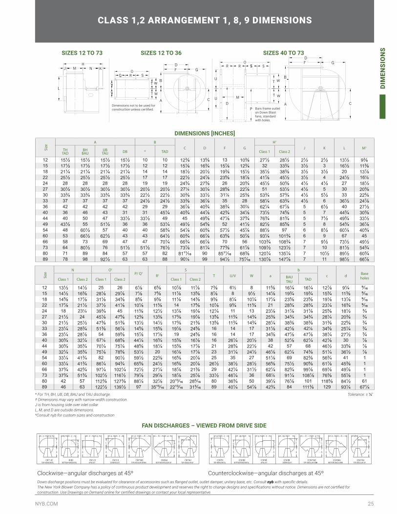
25NYB.COM
DIM
ENSI
ON
S
DIMENSIONSCLASS 1,2 ARRANGEMENT 1, 8, 9 DIMENSIONS
DIMENSIONS [INCHES]
Size
A BC D F G
H†
J K L M†TH
TADBH
BAUUB
TAU DB * TAD Class 1 Class 2
12 151/2 151/2 151/2 151/2 10 10 123/8 135/8 13 103/8 271/2 281/2 21/2 21/2 131/2 93/815 171/2 171/2 171/2 171/2 12 12 151/8 163/4 157/8 123/4 32 333/4 31/2 3 161/2 113/818 211/4 211/4 211/4 211/4 14 14 181/2 201/2 193/8 151/2 351/2 383/8 31/2 31/2 20 137/822 251/2 251/2 251/2 251/2 17 17 221/2 247/8 235/8 187/8 417/8 451/2 31/2 4 241/2 16⅞24 28 28 28 28 19 19 243/4 273/8 26 203/4 451/2 503/8 41/2 41/2 27 181/227 301/2 301/2 301/2 301/2 201/2 201/2 27¼ 301/4 285/8 227/8 51 531/2 41/2 5 30 203/830 333/4 333/4 333/4 333/4 221/2 221/2 303/8 331/2 31⅞ 253/8 533/4 573/4 41/2 51/2 33 225/833 37 37 37 37 241/2 241/2 333/8 367/8 35 28 581/4 633/4 41/2 6 361/2 247/836 42 42 42 42 29 29 367/8 403/4 383/4 30⅞ 621/4 677/8 5 61/2 40 271/240 36 46 43 31 31 451/4 403/4 447/8 423/4 341/8 731/2 745/8 5 7 443/4 303/844 40 50 47 331/2 331/2 49 45 495/8 471/8 373/4 763/4 813/4 5 71/2 493/4 331/249 431/2 55 511/2 36 36 531/4 491/2 545/8 52 411/2 821/2 855/8 5 8 543/4 367/854 48 601/2 57 40 40 583/4 547/8 603/8 571/2 457/8 881/2 97 6 81/2 601/4 403/460 53 661/2 621/2 43 43 641/2 603/4 667/8 635/8 507/8 931/4 1013/4 6 9 67 4566 58 73 69 47 47 701/4 663/4 667/8 70 56 1033/4 1083/4 7 91/2 731/2 491/273 64 801/2 76 511/2 511/2 761/2 737/8 811/4 773/8 617/8 1091/2 1231/2 7 10 811/2 543/480 71 89 84 57 57 82 8111/16 90 8511/16 683/8 1201/4 1351/4 7 101/2 891/2 603/489 78 98 921/2 63 63 88 90⅛ 99 941/2 757/16 1307/8 1477/8 7 11 981/2 667/8
* For TH, BH, UB, DB, BAU and TAU discharge. † Dimensions may vary with narrow-width construction. J is from housing side over inlet collar.L, M, and D are outside dimensions.*Consult nyb for custom sizes and construction
Size
N O†
P/ Q†
R†
ST U/V W a
bc d Base
holesClass 1 Class 2 Class 1 Class 2 Class 1 Class 2 BAUTAU TAD
12 131/2 141/2 25 26 61/8 65/8 107/8 117/8 73/8 6½ 8 115/8 161/4 161/4 127/8 91/4 9/1615 141/2 163/8 281/8 297/8 71/8 75/8 117/8 135/8 87/8 8 91/2 141/8 193/4 193/4 153/4 113/8 9/1618 145/8 177/8 311/8 343/8 85/8 93/8 111/8 143/8 93/8 81/4 101/4 171/4 235/8 235/8 191/8 137/8 9/1622 177/8 211/2 371/2 411/8 101/8 113/8 14 175/8 107/8 93/4 113/4 21 283/4 283/4 231/4 163/4 9/1624 18 23¼ 393/4 45 113/8 121/2 137/8 191/8 121/4 11 13 231/8 317/8 317/8 255/8 181/2 3/427 211/2 24 451/8 475/8 123/8 133/8 173/8 197/8 135/8 113/4 143/4 253/8 343/4 343/4 281/4 203/8 3/430 211/2 251/2 473/8 513/8 131/2 141/2 173/8 213/8 135/8 113/4 143/4 281/4 383/8 383/8 313/8 225/8 3/433 231/4 283/4 513/8 567/8 145/8 155/8 191/8 245/8 16 14 17 311/8 421/8 42⅛ 345/8 251/4 3/436 231/4 287/8 54 595/8 157/8 171/8 19 245/8 16 14 17 343/8 477/8 477/8 381/4 271/2 3/440 303/4 321/4 67⅛ 685/8 441/4 163/4 153/8 161/8 16 261/4 201/2 38 521/8 621/4 421/8 30 7/844 303/4 353/4 701/4 751/4 485/8 181/4 153/8 177/8 21 283/4 221/2 42 57 68 461/2 335/8 7/849 321/4 353/4 751/8 785/8 531/2 20 161/8 177/8 23 311/4 241/2 461/8 621/4 743/8 511/4 361/2 7/854 331/4 413/4 82 901/2 591/2 223/8 165/8 207/8 25 35 27 511/8 69 823/8 563/4 41 160 331/4 413/4 861/4 943/4 655/8 241/2 165/8 207/8 261/2 381/2 281/2 565/8 751/2 905/8 617/8 453/8 166 373/4 423/4 971/4 1021/4 721/2 271/4 187/8 213/8 29 421/4 311/2 621/4 823/4 991/8 691/8 497/8 173 373/4 513/4 1021/2 1161/2 797/8 297/8 187/8 257/8 331/2 461/4 36 68⅞ 911/4 1087/8 763/8 551/8 180 42 57 1123/8 1273/8 881/4 327/8 2013/16 285/16 80 363/4 50 391/4 761/8 101 1185/8 841/2 61 89 46 63 1221/2 1391/2 97 3515/16 2213/16 315/16 89 401/4 547/8 423/4 84 1113/8 129 931/4 671/4
Tolerance: ± 1/8″
SG
C
DF
B
A
OR
T
M T
R
PD
U
UA
D
B
C
F GM
T
T
SS
W
W
W
W
SRO
Q
HJ KN
L
Dimensions not to be used for construction unless certified. Bars frame outlet
on Down Blastfans, standardwith holes.
SIZES 12 TO 73 SIZES 12 TO 36 SIZES 40 TO 73
FAN DISCHARGES – VIEWED FROM DRIVE SIDE
BOTTOM HORIZONTAL
B
F G
C CB
TOP HORIZONTALCCW TH
A A
CCW BH CCW TADTOP ANGULAR DOWN
G F
B C
FG
UP BLASTCCW UB
A
CCW DB
A
DOWN BLAST BOTTOM ANGULAR UP
AA
CCW BAUTOP ANGULAR UP
CCW TAU
A
DOWN BLASTTOP HORIZONTALCW T HC W BH
BOTTOM HORIZONTALCW U B
UP BLAST
A
F
BC
A
G
A
B
CB GF
CW BAUBOTTOM ANGULAR UPTOP ANGULAR DOWN
CW TADCW D B CW TAUTOP ANGULAR UP
A
C
A A
FG
A
Clockwise—angular discharges at 45º Counterclockwise—angular discharges at 45ºDown discharge positions must be evaluated for clearance of accessories such as flanged outlet, outlet damper, unitary base, etc. Consult nyb with specific details.The New York Blower Company has a policy of continuous product development and reserves the right to change designs and specifications without notice. Dimensions are not certified for construction. Use Drawings on Demand online for certified drawings or contact your local representative.
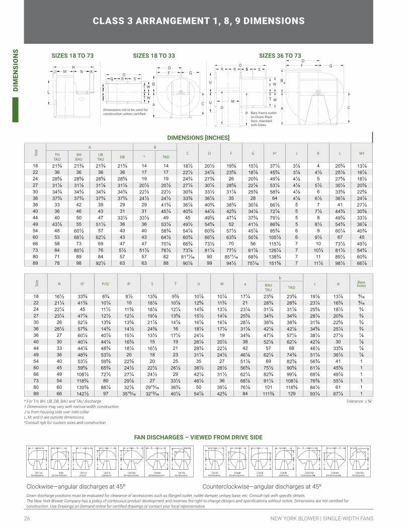
26 NEW YORK BLOWER | SINGLE-WIDTH FANS
DIM
ENSI
ON
S
Size N O† P/Q† R† S T U W a
bc d Base
holesBAUTAU TAD
18 161/2 335/8 83/4 81/2 133/8 93/8 107/8 101/4 171/4 235/8 235/8 191/8 137/8 9/1622 211/4 413/8 101/4 10 181/8 107/8 125/8 113/4 21 283/4 283/4 231/4 163/4 9/1624 221/4 45 111/2 113/8 181/8 121/4 143/8 131/2 231/8 317/8 317/8 255/8 181/2 3/427 231/4 477/8 121/2 121/4 191/8 135/8 151/2 147/8 253/8 343/4 343/4 281/4 203/8 3/430 26 527/8 135/8 133/8 217/8 147/8 167/8 161/8 281/4 383/8 383/8 313/8 225/8 3/436 281/2 575/8 143/4 141/2 243/8 16 181/4 171/4 311/8 421/8 421/8 345/8 251/4 3/436 27 601/2 401/4 151/4 131/2 171/2 241/2 19 343/8 477/8 571/4 381/4 271/2 7/840 30 401/4 441/4 163/4 15 19 261/4 201/2 38 521/8 621/4 421/8 30 7/844 33 441/4 483/4 181/4 161/2 21 283/4 221/2 42 57 68 461/2 335/8 7/849 36 483/4 531/2 20 18 23 311/4 241/2 461/8 621/4 743/8 511/4 361/2 7/854 40 531/2 595/8 223/8 20 25 35 27 511/8 69 823/8 563/4 41 160 45 595/8 653/4 241/2 221/2 261/2 381/2 281/2 565/8 751/2 905/8 617/8 453/8 166 49 1081/2 721/2 271/4 241/2 29 421/4 311/2 621/4 823/4 991/8 691/8 497/8 173 54 1183/4 80 297/8 27 331/2 461/4 36 687/8 911/4 1087/8 763/8 551/8 180 60 1303/8 881/4 327/8 2913/16 363/4 50 391/4 761/8 101 1185/8 841/2 61 189 66 1421/2 97 3515/16 3213/16 401/4 547/8 423/4 84 1113/8 129 931/4 671/4 1
CLASS 3 ARRANGEMENT 1, 8, 9 DIMENSIONS
DIMENSIONS [INCHES]
Size
A BC D F G H† J K L M†TH
TADBH
BAUUB
TAU DB * TAD
18 213/4 213/4 213/4 213/4 14 14 181/2 201/2 193/8 151/2 371/2 31/8 4 203/4 137/822 36 36 36 36 17 17 221/2 247/8 235/8 187/8 453/4 31/8 41/2 251/8 167/824 285/8 285/8 285/8 285/8 19 19 243/4 273/8 26 203/4 497/8 41/8 5 275/8 181/227 311/8 311/8 311/8 311/8 201/2 201/2 271/4 301/4 285/8 227/8 531/4 41/8 51/2 301/4 203/830 343/4 343/4 343/4 343/4 221/2 221/2 303/8 331/2 317/8 253/8 583/4 41/8 6 335/8 225/836 373/4 373/4 373/4 373/4 241/2 241/2 333/8 367/8 35 28 64 41/8 61/2 367/8 247/836 33 42 39 29 29 413/4 367/8 403/4 383/4 307/8 661/2 5 7 41 271/240 36 46 43 31 31 451/4 403/4 447/8 423/4 341/8 727/8 5 71/2 443/4 303/844 40 50 47 331/2 331/2 49 45 495/8 471/4 373/4 791/2 5 8 493/4 331/249 431/2 55 511/2 36 36 531/4 491/2 545/8 52 411/2 863/8 5 81/2 543/4 367/854 48 601/2 57 40 40 583/4 547/8 603/8 571/2 457/8 953/4 6 9 601/4 403/460 53 661/2 621/2 43 43 641/2 603/4 667/8 633/4 507/8 1051/2 6 91/2 67 4566 58 73 69 47 47 701/4 663/4 731/2 70 56 1151/2 7 10 731/2 491/273 64 801/2 76 51/2 511/2 761/2 737/8 811/4 771/2 617/8 1261/4 7 101/2 811/2 543/480 71 89 84 57 57 82 8111/16 90 8511/16 683/8 1383/4 7 11 891/2 603/4 89 78 98 921/2 63 63 88 901/8 99 941/2 757/16 1513/8 7 111/2 981/2 667/8
FAN DISCHARGES – VIEWED FROM DRIVE SIDE
BOTTOM HORIZONTAL
B
F G
C CB
TOP HORIZONTALCCW TH
A A
CCW BH CCW TADTOP ANGULAR DOWN
G F
B C
FG
UP BLASTCCW UB
A
CCW DB
A
DOWN BLAST BOTTOM ANGULAR UP
AA
CCW BAUTOP ANGULAR UP
CCW TAU
A
DOWN BLASTTOP HORIZONTALCW T HC W BH
BOTTOM HORIZONTALCW U B
UP BLAST
A
F
BC
A
G
A
B
CB GF
CW BAUBOTTOM ANGULAR UPTOP ANGULAR DOWN
CW TADCW D B CW TAUTOP ANGULAR UP
A
C
A A
FG
A
BOTTOM HORIZONTAL
B
F G
C CB
TOP HORIZONTALCCW TH
A A
CCW BH CCW TADTOP ANGULAR DOWN
G F
B C
FG
UP BLASTCCW UB
A
CCW DB
A
DOWN BLAST BOTTOM ANGULAR UP
AA
CCW BAUTOP ANGULAR UP
CCW TAU
A
DOWN BLASTTOP HORIZONTALCW T HC W BH
BOTTOM HORIZONTALCW U B
UP BLAST
A
F
BC
A
G
A
B
CB GF
CW BAUBOTTOM ANGULAR UPTOP ANGULAR DOWN
CW TADCW D B CW TAUTOP ANGULAR UP
A
C
A A
FG
A
Clockwise—angular discharges at 45º Counterclockwise—angular discharges at 45ºDown discharge positions must be evaluated for clearance of accessories such as flanged outlet, outlet damper, unitary base, etc. Consult nyb with specific details.The New York Blower Company has a policy of continuous product development and reserves the right to change designs and specifications without notice. Dimensions are not certified for construction. Use Drawings on Demand online for certified drawings or contact your local representative.
* For TH, BH, UB, DB, BAU and TAU discharge. † Dimensions may vary with narrow-width construction. J is from housing side over inlet collar.L, M, and D are outside dimensions.*Consult nyb for custom sizes and construction
Tolerance: ± 1/8″
SG
C
DF
B
A
OR
T
M T
R
PD
U
UA
D
B
C
F GM
T
T
SS
W
W
W
W
SRO
Q
HJ KN
L
Dimensions not to be used for construction unless certified. Bars frame outlet
on Down Blastfans, standardwith holes.
SIZES 18 TO 73 SIZES 18 TO 33 SIZES 36 TO 73
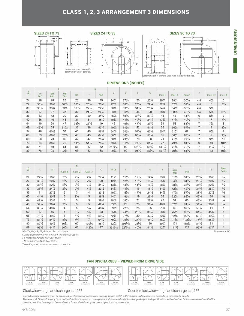
27NYB.COM
DIM
ENSI
ON
S
CLASS 1, 2, 3 ARRANGEMENT 3 DIMENSIONS
DIMENSIONS [INCHES]
Size
A BC D F G
HJ
K
THTAD
BHBAU
UBTAU DB * TAD Class 1 Class 2 Class 3 Class 1,2 Class 3
24 28 28 28 28 19 19 243/4 273/8 26 203/4 293/4 293/4 301/4 41/8 41/2 527 301/2 301/2 301/2 301/2 201/2 201/2 271/4 301/4 285/8 227/8 321/8 321/8 325/8 41/8 5 51/230 333/4 333/4 333/4 333/4 221/2 221/2 303/8 331/2 317/8 253/8 347/8 347/8 357/8 41/8 51/4 633 37 37 37 37 241/2 241/2 333/8 367/8 35 28 385/8 385/8 405/8 51/8 53/4 61/236 33 42 39 29 29 413/4 367/8 403/4 383/4 307/8 43 43 441/2 6 61/2 740 36 46 43 31 31 451/4 403/4 447/8 423/4 341/8 473/8 471/2 497/8 7 7 71/244 40 50 47 331/2 331/2 49 45 495/8 471/8 373/4 51 53 531/2 7 71/2 849 431/2 55 511/2 36 36 531/4 491/2 545/8 52 411/2 55 567/8 573/8 7 8 81/254 48 601/2 57 40 40 583/4 547/8 603/8 571/2 457/8 601/4 611/4 62 7 81/2 960 53 661/2 621/2 43 43 641/2 603/4 667/8 633/4 507/8 65 661/4 671/8 7 9 91/266 58 73 69 47 47 701/4 663/4 731/2 70 56 71 711/4 721/8 7 91/2 1073 64 801/2 76 511/2 511/2 761/2 737/8 811/4 771/2 617/8 77 793/8 811/4 9 10 101/280 71 89 84 57 57 82 8111/16 90 8511/16 683/8 1391/4 711/4 721/8 7 111/2 1089 78 98 921/2 63 63 88 901/8 99 941/2 757/16 1517/8 793/8 811/4 7 12 101/2
Size L M
NO P/ Q R T U a
bc d Base
holesClass 1 Class 2 Class 3 BAUTAU TAD
24 275/8 181/2 25/8 25/8 25/8 271/8 111/2 111/2 121/4 143/8 231/8 317/8 317/8 255/8 181/2 3/427 301/4 203/8 25/8 25/8 25/8 29 121/2 121/2 135/8 151/2 253/8 343/4 343/4 281/4 203/8 3/430 335/8 225/8 27/8 27/8 31/8 311/4 135/8 135/8 147/8 167/8 281/4 383/8 383/8 313/8 225/8 3/433 367/8 247/8 27/8 27/8 41/8 331/2 143/4 143/4 16 181/4 311/8 421/8 421/8 345/8 251/4 3/436 41 271/2 3 3 4 331/2 401/4 151/4 171/2 241/2 343/8 477/8 571/4 381/4 271/2 7/840 443/4 303/8 3 31/8 5 363/8 441/4 163/4 19 261/4 38 521/8 621/4 421/8 30 7/844 493/4 331/2 3 5 5 391/2 485/8 181/4 21 283/4 42 57 68 461/2 335/8 7/849 543/4 367/8 31/8 5 5 427/8 531/2 20 23 311/4 461/8 621/4 743/8 511/4 361/2 7/854 601/4 403/4 4 5 51/4 483/4 591/2 223/8 25 35 511/8 69 823/8 563/4 41 160 67 45 4 51/4 53/8 53 655/8 241/2 261/2 381/2 565/8 751/2 905/8 617/8 453/8 166 731/2 491/2 5 51/4 55/8 591/2 721/2 271/4 29 421/4 621/4 823/4 991/8 691/8 497/8 173 811/2 543/4 51/4 55/8 7 643/4 797/8 297/8 331/2 461/4 687/8 911/4 1087/8 763/8 551/8 180 891/2 491/2 603/4 60 1303/8 881/4 327/8 2913/16 363/4 50 391/4 101 1185/8 841/2 61 189 981/2 543/4 667/8 66 1421/2 97 3515/16 3213/16 401/4 547/8 423/4 1113/8 129 931/4 671/4 1
FAN DISCHARGES – VIEWED FROM DRIVE SIDE
BOTTOM HORIZONTAL
B
F G
C CB
TOP HORIZONTALCCW TH
A A
CCW BH CCW TADTOP ANGULAR DOWN
G F
B C
FG
UP BLASTCCW UB
A
CCW DB
A
DOWN BLAST BOTTOM ANGULAR UP
AA
CCW BAUTOP ANGULAR UP
CCW TAU
A
DOWN BLASTTOP HORIZONTALCW T HC W BH
BOTTOM HORIZONTALCW U B
UP BLAST
A
F
BC
A
G
A
B
CB GF
CW BAUBOTTOM ANGULAR UPTOP ANGULAR DOWN
CW TADCW D B CW TAUTOP ANGULAR UP
A
C
A A
FG
A
BOTTOM HORIZONTAL
B
F G
C CB
TOP HORIZONTALCCW TH
A A
CCW BH CCW TADTOP ANGULAR DOWN
G F
B C
FG
UP BLASTCCW UB
A
CCW DB
A
DOWN BLAST BOTTOM ANGULAR UP
AA
CCW BAUTOP ANGULAR UP
CCW TAU
A
DOWN BLASTTOP HORIZONTALCW T HC W BH
BOTTOM HORIZONTALCW U B
UP BLAST
A
F
BC
A
G
A
B
CB GF
CW BAUBOTTOM ANGULAR UPTOP ANGULAR DOWN
CW TADCW D B CW TAUTOP ANGULAR UP
A
C
A A
FG
A
Clockwise—angular discharges at 45º Counterclockwise—angular discharges at 45ºDown discharge positions must be evaluated for clearance of accessories such as flanged outlet, outlet damper, unitary base, etc. Consult nyb with specific details.The New York Blower Company has a policy of continuous product development and reserves the right to change designs and specifications without notice. Dimensions are not certified for construction. Use Drawings on Demand online for certified drawings or contact your local representative.
* For TH, BH, UB, DB, BAU and TAU discharge. † Dimensions may vary with narrow-width construction. J is from housing side over inlet collar.L, M, and D are outside dimensions.*Consult nyb for custom sizes and construction
Tolerance: ± 1/8″
F GD
C
B
A
T
T
U
UP D
M
R RO
C
B
A
F GD
T
T
U
U
Q RO
L
J M NK
H
Dimensions not to be used for construction unless certified.
Bars frame outlet on Down Blast fans, standard with holes.
SIZES 24 TO 73 SIZES 24 TO 33 SIZES 36 TO 73

PRODUCTSOur commitment to total customer satisfaction is proven with our consistent investment in product development. Our AMCA accredited lab uses modern testing techniques to guarantee fan performance and reliability.
Our technicians are highly qualified in repairing, rebuilding, modifying and retrofitting any manufacturer’s equipment. Fan assemblies can be tested in the field or at our lab for air, sound and vibration problems.
Our extensive operations include over 490,000 ft2 of manufacturing space in the United States, and over 200,000 ft2
internationally. The map shows both manufacturing and representative offices worldwide.
WORLDWIDE PRESENCE
800-208-7918 | nyb.com
THE NEW YORK BLOWER COMPANY
INLINE FANSDuct FansIndustrial Duct FansTubeaxialVaneaxialVaneaxial Fixed PitchDirect Drive Vaneaxial Fixed PitchVaneaxial Adjustable PitchTubular AcoustaFoil™Propeller Fans
CENTRIFUGAL FANSForward CurvedBackward InclinedRadialRadial TipPressure Blowers
CUSTOM FANS
CENTRIFUGAL VENTILATOR FANSGeneral Purpose FansSquare FansJunior Fans
AXIAL VENTILATOR PRODUCTSUpblast Roof VentilatorsHooded Roof VentilatorsCentrifugal Roof Ventilators
PLENUMS AND DOUBLE WIDTHSAirfoil PlenumCube Array Plenum FansBackward Inclined DWDIFA / EZ PlenumForward Curved DWD
FIBERGLASS REINFORCED PLASTIC FANSFRP Fume ExhausterFRP General Purpose Fume ExhausterFRP Pressure BlowerFRP Radial Fume Exhauster
PROCESS HEAT OR PLUG FANSAir KitsPlug FansOEM Wheels and Cones
FAN COMPONENTS
SILENCERS/FLEX CONNECTORS
STEAM COIL PRODUCTSUnit HeatersSteelfin Coils
Replacement Parts
MANUFACTURING LOCATIONSUNITED STATES Ashville, NCEffingham, ILLaPorte, INLeitchfield, KYNew Castle, PA
INTERNATIONAL Australia—MelbourneChina—Kunshan China—SuqainNew Zealand—AucklandNew Zealand—Wellington
Philippines—ManilaSingaporeTaiwan—TaipeiVietnam—Ho Chi Minh City
AFTERMARKET SERVICES
Field ServicesRepair & RebuildAftermarket Retrofit
Replacement PartsPreventative MaintenanceEngineering Analysis
Testing CapabilitiesBalancing Capabilities
- representative office - manufacturing facility - corporate headquarters