australian road barriers
TRANSCRIPT

INSTALLATION & MAINTENANCE INSTRUCTIONS
Concrete Safety Barriers
from
AUSTRALIAN ROAD BARRIERS
Under License from the Trademark Proprietor, Easi-Set Industries, Midland, Virginia, USA.
AUSTRALIAN ROAD BARRIERS PTY LTD RMB H535, BALLARAT, VIC 3352
ABN 91 121 470 102
Freecall: 1800 003 826 ● Fax: 03 5339 9273 ● Email: [email protected]
®

Revision History
Revision Amendments Authorised Initial Release. L.McKenna
April 2006 1. QLD Department of Main Roads approval letter added. 2. Miscellaneous minor corrections.
J.Govan
August 2006 1. SA Department of Transport, Energy and Infrastructure approval letter added. 2. Section 3.3 Estimated Deflections
J.Govan
July 2008 1. Major Revision. 2. Layout and Format Changes. 3. Information added regarding lifting and slinging, installation procedure and delineation requirements.
J.Govan
April 2009 1. Section 2.1 Site Conditions 2. Section 2.8 Delineation 3. Important Notes
J Govan
IMPORTANT NOTES
1. This manual must be read in conjunction with the Road Authorities guidelines, the site specific risk assessment and the traffic management plan for the worksite.
2. The road authorities in each state reserve the right to approve,
reject or restrict the use of specific products within the road reserve. If you are unsure of the current status of any products within this manual please contact Australian Road Barriers on 1800 003 826.
3. J-J Hooks® Safety Barriers are not warranted to prevent any
injury or loss due to any accident howsoever caused but may significantly reduce the consequences of such an accident.
4. It is the responsibility of the end user to assess the risks
associated with the use of (or the failure to use) a safety barrier system tested in accordance with the NCHRP Report 350 test methods, and with the particular site and traffic conditions for which barriers are being considered.

TABLE OF CONTENTS
IMPORTANT NOTES II
1. INTRODUCTION 1
2. DESIGN . 2
2.1 SITE CONDITIONS 2 2.2 SITE GEOMETRY 3 2.3 WORKING WIDTH 3 2.4 ATMOSPHERIC CONDITIONS 3 2.5 EMERGENCY ACCESS 3 2.6 MINIMUM LENGTH 4 2.7 TERMINATING THE SAFETY BARRIER 4 2.8 DELINEATION 4
3. INSTALLATION 5 3.1 RESOURCES REQUIRED 5 3.2 LIFTING PROCEDURE 5
3.2.1. Pre Lift Inspection 5 3.2.2. Sling Angle 6 3.2.3. Lifting 6
3.3 INSTALLATION SEQUENCE 7 3.4 INSTALLATION PROCEDURE 7 3.5 SITE SCREENS 8 3.6 MAINTENANCE 8 3.7 INCIDENT REPORTING 8
4. COMPLIANCE ISSUES 9
4.1 CRASH TEST 9 4.2 AUSTRALIAN STANDARDS 9 4.3 ESTIMATED DEFLECTIONS 10
APPENDIX 1. OPTIONAL END TREATMENTS 11
APPENDIX 2. WORKSAFE / VICROADS SAFETY BARRIER CHECKLIST 13
APPENDIX 3. ROAD AUTHORITY APPROVALS 16

- 1 -
Revised July 2008
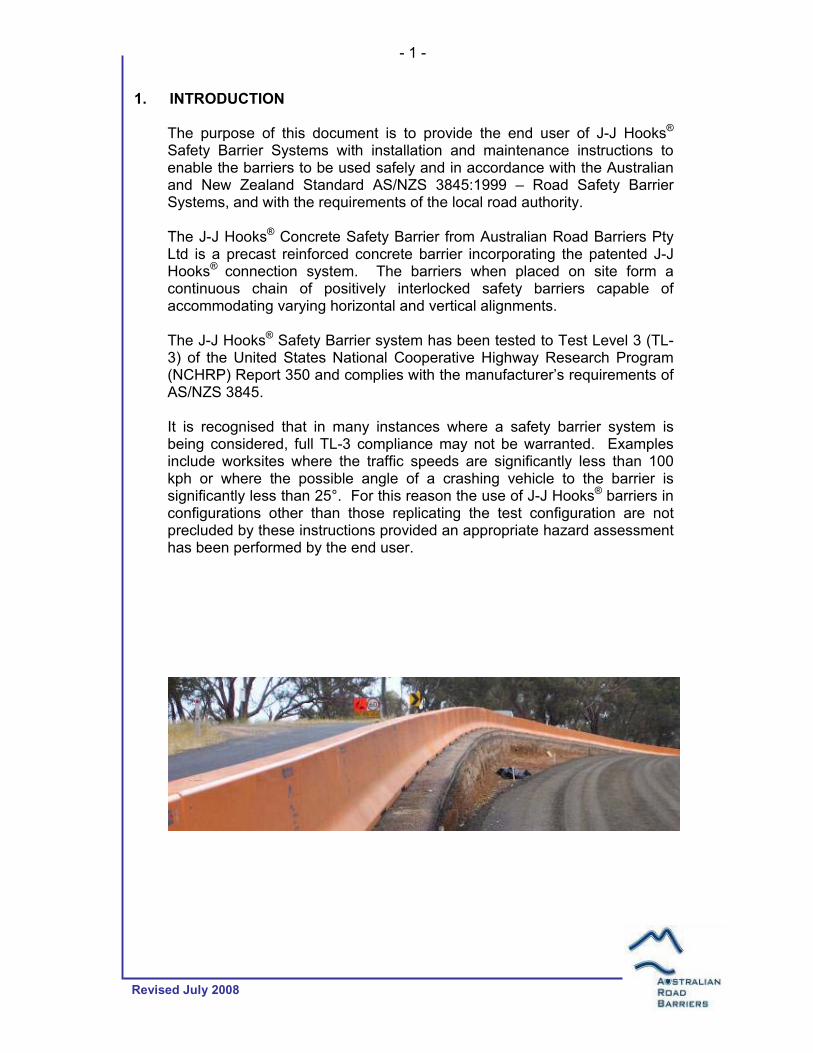
1. INTRODUCTION
The purpose of this document is to provide the end user of J-J Hooks® Safety Barrier Systems with installation and maintenance instructions to enable the barriers to be used safely and in accordance with the Australian and New Zealand Standard AS/NZS 3845:1999 – Road Safety Barrier Systems, and with the requirements of the local road authority. The J-J Hooks® Concrete Safety Barrier from Australian Road Barriers Pty Ltd is a precast reinforced concrete barrier incorporating the patented J-J Hooks® connection system. The barriers when placed on site form a continuous chain of positively interlocked safety barriers capable of accommodating varying horizontal and vertical alignments. The J-J Hooks® Safety Barrier system has been tested to Test Level 3 (TL-3) of the United States National Cooperative Highway Research Program (NCHRP) Report 350 and complies with the manufacturer’s requirements of AS/NZS 3845. It is recognised that in many instances where a safety barrier system is being considered, full TL-3 compliance may not be warranted. Examples include worksites where the traffic speeds are significantly less than 100 kph or where the possible angle of a crashing vehicle to the barrier is significantly less than 25°. For this reason the use of J-J Hooks® barriers in configurations other than those replicating the test configuration are not precluded by these instructions provided an appropriate hazard assessment has been performed by the end user.

2. DESIGN .
Prior to the installation of any safety barrier system the end user should give consideration to a range of items, including, but not limited to:
• Site conditions, geometry and working width; • The length of barrier to be installed and the safe termination of the
system; • Site access requirements, including emergency access; • Any requirements for site screens, delineation, signage, etc.; and • The results of any Risk Assessments undertaken for the project.
VicRoads and WorkSafe Victoria have jointly developed a checklist for temporary safety barriers, titled ‘Roadside Worksite Traffic Management Checklist Temporary Safety Barriers’ (refer Appendix B). While the checklist is primarily designed for use as an on-site inspection tool, Australian Road Barriers recommends that reference to the document is made at the design stage. 2.1 Site Conditions J-J Hooks® Barriers must be placed on a flat, stable and compacted surface capable of being trafficked by road vehicles for short periods. The crossfall must not exceed 6%. Unstable surfaces such as deep mud, uncompacted sand or excessively wet surfaces are considered inappropriate. Ideally the surface should be paved and must be free of swales, ditches or other irregularities. The minimum width of stable ground behind the barriers must not be less than the expected deflection of the barrier system (refer 4.3 below). Barriers must be placed at the same level as the travelled lane and must not be placed in front, behind or on top of kerbing.

- 3 -
Revised July 2008
2.2 Site Geometry Barriers should (where practicable) be placed parallel to the travelled lane and as far away from the travelled lane as possible. J-J Hooks® barriers are capable of a horizontal curvature of approx. 30 metres radius (left or right), and a vertical curvature of 30 metres radius in sag and 53 metres on a crest. Barriers should be placed at the same level as the travelled lane and should not be placed in front, behind or on top of kerbing. 2.3 Working Width The minimum working width required for the J-J Hooks® Barriers is the total of the width of the base of the barrier (being 606mm) plus the expected maximum deflection (refer 4.3 below) and the required offset from the edge of the traffic lane.
2.4 Atmospheric Conditions J-J Hooks® barriers are suitable for use in all atmospheric conditions normally encountered on Australian roads without any reduction in effectiveness. 2.5 Emergency Access Emergency access through J-J Hooks® barriers can be achieved by simply lifting the appropriate number of barriers vertically from the line and placing them to one side behind the remaining barriers. If the emergency opening is to be left open, appropriate measures must be taken to treat the exposed ends of the barriers.
TRAFFIC
Not to Scale Based on Figure 13 – Safety Barrier Clearance from the Victorian Worksite Safety – Traffic Management Code of Practice.
606 mm
Offset from
Traffic Lane
Edge of Traffic Lane
Expected Maximum Deflection
Work Zone
Working Width
810
mm

2.6 Minimum Length Given an appropriate hazard assessment, J-J Hooks® barriers can be installed in any length. In order to replicate the TL-3 test conditions a minimum of 21.6 metres of barrier should be laid upstream and downstream of the point at which the test deflection is to be achieved. Note: some of the State Road Authorities specify a minimum installation length which may be greater than that recommended above. 2.7 Terminating the Safety Barrier The ends of safety barriers must be appropriately treated to avoid creating additional hazards. A separate end treatment is not required if the line of the barriers can be flared so that the exposed end is located outside the clear zone for the particular site. The width of the clear zone shall be as recommended by the local road authority and is dependant on the traffic speed and (sometimes) on the traffic volume. The flare rate should be not steeper than 10 to 1. Each type of end treatment has its own advantages and disadvantages and in some circumstances, new hazards may be created through their use. It is the responsibility of the user to assess the suitability of any end treatment to the site conditions. End treatments recommended by Australian Road Barriers are described in Appendix 1. Users should be aware that on a two lane two way carriageway, the departure end of a barrier system may require end treatment as it may be considered an approach end to the opposing traffic. 2.8 Delineation Consideration should be given to the visibility of the barrier system during all climatic conditions. The provision of any one, or combination, of the following may assist in the delineation of both the barrier system and the travelled path:
• Pavement markings including but not limited to edge/fog line markings and painted lateral shift arrows;
• Raised Reflective Pavement Markers (RRPMs); • Corner cube reflectors; and • Signage.
Australian Road Barriers is able to supply, upon request, either corner cube reflectors or temporary raised reflective markers which can be attached to the J-J Hooks® Barriers. The selection and spacing of the delineation should be in accordance with the Road Authorities guidelines, the site specific risk assessment and the traffic management plan for the worksite.

- 5 -
Revised July 2008
3. INSTALLATION 3.1 Resources Required The following are the minimum resources required for the safe installation of J-J Hooks® barriers:
• 2 x 2.5 Tonne Swiftlift lifting clutches or equivalent for the 3.6m units or 2 x 5.0 Tonne Swiftlift lifting clutches or equivalent for the 6.0m units;
• 1 x chain sling – ideally a 2 leg Grade 80, 10 mm chain sling; • Tag/Control line (Optional at discretion of dogman giving
consideration to site layout, lifting procedure, etc.); • 1 x Crane, Crane Truck or plant with a certified lifting point capable
of safely lifting the barrier at the required offset (standard 3.6 m barrier is 2.5 tonne, standard 6.0 m barrier is 4.3 tonne), capable of a vertical lift of 1 metre and with a clearance from hook to ground of at least 3.8 metres;
• Crane or plant operator; • Dogman or crane chaser equipped with safety boots, gloves and any
other PPE required at the particular site; • Traffic control as appropriate to the site and as required by the local
road authority. 3.2 Lifting Procedure
3.2.1. Pre Lift Inspection
Prior to lifting a J-J Hooks® Barrier the following items must be inspected:
• Lifting anchors for wear, corrosion, deformation or cracking. The lifting anchors are located in the top surface of each barrier, ¼ of the length of the barrier in from each end. Do not lift barriers using the swift lifts if wear or corrosion exceeds 10%, or if the swift lift is deformed or cracked.
• The J-J Hooks® Barrier for structural damage, signs of impact or cracking (excluding shrinkage cracks). Exercise due care when lifting barriers which show evidence of structural damage.
Note: J-J Hooks® Barriers contain SL718 reinforcing mesh in each face providing a fully reinforced concrete product. Shrinkage cracking is normal and will not reduce the serviceability of the barrier or increase the risks associated with lifting the barrier.
• For barriers currently connected the joint must be checked for debris and cleaned if necessary to minimise the risk of snagging during the lifting process.

3.2.2. Sling Angle The lifting anchors used in all Australian produced J-J Hooks® barriers have been designed for a maximum sling angle of 60o.
The easiest way to ensure that the sling angle is not exceeded is to make sure that each leg of the chain sling is longer than the distance between the lifting anchors. Alternatively you can measure from the top of the barrier to the underside of the Master Link prior to lifting the barrier. The minimum heights should be 1600mm for a 3.6m barriers and 2.6m for the 6.0m barriers. 3.2.3. Lifting It is essential that:
• The lifting clutches, chains, etc. are attached by suitably trained and experienced operators and/or personnel.
• Only one barrier is lifted at a time. • The tabs of the lifting clutches are aligned with the chain sling. • The lifting point of the crane is positioned over the centre of the
barrier prior to commencing the lift. • Barriers are lifted evenly and remain horizontal. • Barriers are lifted and positioned as smoothly as possible to
avoid barrier damage and impact loading the lifting apparatus and crane.
• If the connection snags, stop the lift and either remove the debris causing the snag or adjust the chain sling.
Tag/control lines are optional and should be used whenever the dogman determines that the risks associated with rotation of the barriers outweigh those introduced by the use of a line.
Not to Scale
60o or less
Master Link

- 7 -
Revised July 2008
3.3 Installation Sequence Working in the direction of the adjacent traffic, commence the installation of the barriers at the approach end of the system and work through to the departure end. Barriers should be installed sequentially to ensure that the correct installation spacing is achieved. If a gap is required within a run of barriers the barriers should be installed through and past the gap and then removed. This will ensure that the barriers adjacent to the gap are appropriately spaced. End treatments on the approach side of barriers should be installed as soon as practicable after the first barrier(s) are being placed. Barriers should be removed in the reverse order. 3.4 Installation Procedure
• Ensure that appropriate temporary traffic management is in place for the barrier installation process. This may include, temporary road or lane closures, speed restrictions, etc.
• Set/mark out the barrier alignment; • Attach lifting clutches to the lifting anchors cast in the top of the
barriers; • Attach a suitable chain sling to the lifting clutches and position the
crane or lifting plant so that the hook or lifting point is directly above the centre of the barrier;
• Lift the first barrier into position; • Work from the non-trafficked side of the barrier(s) wherever
possible; • Lift each subsequent barrier into position - each barrier must be
lifted high enough so that the bottom of the engaging hook is above the top of the hook on the preceding barrier (approx 320 mm above the ground). The chaser or dogman should first guide the engaging hook into the adjacent rebate and then move to the other end of the barrier to ensure the desired alignment is achieved.
• Barriers should be placed at their maximum separation to replicate test conditions;
• Visually inspect each installation ensuring there are no objects or ground conditions that cause the barrier joins to be uneven or twisted.

3.5 Site Screens Site screens can be attached to J-J Hooks® Safety Barriers. It is strongly recommended that any screen attached to the barriers have no horizontal compression members and that the screen be offset from the rear of the barrier to allow an errant vehicle to slide along the top of the barrier unencumbered.
It is the user’s responsibility to assess any site screen for compliance with local regulations or road authority requirements.
The RTA of NSW does not allow the use of site screens unless they have been crash tested and assessed. The Site Screens offered by
Australian Road Barriers have not yet been crash tested. 3.6 Maintenance Under normal operating conditions J-J Hooks® barriers require no maintenance other than regular inspections for damage, removal of any litter or debris built up around the barriers and occasional cleaning if the visibility of the barriers is affected. Where the barriers are placed for extended periods in locations where they are exposed to sea water, sea air or in areas where salt is used to control snow, the steel hooks should be regularly cleaned and inspected for signs of corrosion. Hooks showing signs of corrosion (other than surface discoloration) must be reported to Australian Road Barriers so that the barriers can be assessed and replaced as necessary. 3.7 Incident Reporting Incidents that result in significant damage to individual barriers or to the barrier system as a whole must be reported to Australian Road Barriers for investigation and/or replacement. Significant damage would include concrete spalls larger than fist size, deformation of the hooks, any damage to the end treatments or cracking (excluding shrinkage cracks).

- 9 -
Revised July 2008
4. COMPLIANCE ISSUES
4.1 Crash Test The J-J Hooks® barrier system has been tested to the requirements of the NCHRP Report 350 Test Level 3 (TL-3) test 3-11. In the test, a 2050 kg vehicle travelling at 101 kph was crashed into a straight line of J-J Hooks® barriers at an angle of 25° to the line of the barriers. The barriers deflected laterally 1.3 metres. The tested barrier system consisted of 16 interlocked barriers which were struck at barrier 7 (numbered 1 to 16, approach to departure). The tested barriers were free standing on a concrete pavement and were not attached to the pavement in any way. The barrier system contained and redirected the vehicle, the vehicle did not penetrate, under-ride, nor override the installation. 4.2 Australian Standards The J-J Hooks® barrier system complies with the manufacturers requirements of the Australian Standards AS 1742.3:2002 Manual of Uniform Traffic Control Devices, Part 3: Traffic Control Devices for Works on Roads, and AS/NZS 3845:1999 Road Safety Barrier Systems.

4.3 Estimated Deflections In order to assist users in making an informed assessment of the hazards associated with the deflections of J-J Hooks® barrier systems, the estimated deflections in Graph 4.3.1 and Graph 4.3.2 are provided. The values are estimates only. They are based on the test data and the calculated impact severity as defined in Clause 3.3.1 of the NCHRP Report 350. The values do not represent actual test deflections but are estimates of deflections for idealised conditions. The minimum length specified in Clause 2.6 is assumed in the calculations.
10060 80Impact Speed (kph)
Est
imat
ed D
e fle
ctio
n (m
m)
250
800 kg Vehicle
25° Impact Angle
20° Impact Angle
15° Impact Angle
10° Impact Angle
500
50
Graph 4.3.1 – 800 kg Vehicle
100
100
60 80Impact Speed (kph)
Est
imat
ed D
e fle
ctio
n (m
m)
2000 kg Vehicle
20° Impact Angle
15° Impact Angle
25° Impact Angle
10° Impact Angle
500
1000
Graph 4.3.2 – 2000 kg Vehicle

APPENDIX 1. OPTIONAL END TREATMENTS

Barrier Ends Flared Beyond the Clear Zone Wherever possible, the ends of the barrier system should be flared to place the blunt end beyond the clear zone. The width of the clear zone should be as recommended by the local road authority. The flare rate should be a minimum of 10:1 or as recommended by the local road authority.
Proprietary End Treatments Where it is not possible or practical to remove a blunt end beyond the clear zone, a proprietary end treatment such as the ABSORB 350 by Barrier Systems Inc. (pictured) should be installed. Any proprietary system used should be attached to the J-J Hooks® concrete barriers via an adaptor supplied by the manufacturer of the end treatment. Proprietary end treatments fall essentially into two categories, gating and non-gating. A gating end treatment allows a vehicle impacting the nose or the side of the unit at an angle near the nose to pass through the device. Where a gating system is used, allowance must be made for a runoff area behind the device for any vehicle passing through the device. A non-gating or redirective device is capable of redirecting an errant vehicle along the line of the concrete barriers. Gating systems tend to be cheaper to hire or purchase, and cheaper and easier to install. They are often water filled barriers that sit freely on the pavement with the concrete barriers. Non gating redirective systems are more substantial and are often required to be pinned or bolted to the pavement or a footing. Some systems can be supplied with a precast concrete footing that requires excavation to install. Any proprietary end treatment system used with the J-J Hooks® Barrier System must be specifically designed or adapted for use with AASHTO “F” shape barriers and must be installed and maintained strictly in accordance with the manufacturer’s instructions.

APPENDIX 2. WORKSAFE / VICROADS SAFETY BARRIER CHECKLIST


A2 - 2

APPENDIX 3. ROAD AUTHORITY APPROVALS
Victoria, VicRoads, 14 July 2003 (ref: TM 050 29) .................................................. 3-1
New South Wales, RTA, 19 December 2003 (ref: OIM/5896.1) ............................... 3-2
Queensland, Department of Main Roads, 3 March 2006 (ref: 870/811) ................ 3-4
South Australia, Department of Transport Energy and Infrastructure, 18 July 2006 (ref: 2005/09058) ................................................................................. 3-6

A3 - 1


A3 - 3


A3 - 5


A3 - 7