australian technical production services desk psu/small desk supply.pdf · the power supply. this...
TRANSCRIPT

Australian Technical Production Services
Small Desk Supply
Copyright notice.These notes, the design, schematics and diagrams are Copyright Richard Freeman, 2012, 2013While I am happy for the notes to be printed and copied for personal or educational use, they may not be used in any other publication, or published on any other website without written permission.Further information may be found at www.atps.netRevision history:01/02/2013 Add drilling templates, and choosing a heatsink4/02/2013 corrected errors in template and noted error with C12 polarity on PCB mask13/09/2013 Corrected capacitor values
CreditsThis Article contains contributions by:Richard Freeman
Table of ContentsSmall desk supply..........................................................................................................................................2
Circuit description.....................................................................................................................................2Squirting noise into your earth.............................................................................................................3
Construction..............................................................................................................................................4Layout ..................................................................................................................................................4Parts locator..........................................................................................................................................4Assembly..............................................................................................................................................5
Transformer...............................................................................................................................................5Choosing a Transformer.......................................................................................................................6
Heat-sinking requirements........................................................................................................................6Parts list..........................................................................................................................................................9
Hardware...................................................................................................................................................9Inside Template.......................................................................................................................................10Outside Template....................................................................................................................................11
SDP_A rev 1B Page 1

Small desk supplyWhile the original purpose for the supply was a lowish cost replacement for smaller analogue mixing consoles it can also be used for many other uses where +/- 17 volts (other voltages can be set) and +48 volts and 12V is required.The supply uses a voltage multiplier to generate the 48 volt supply so a readily available 15-0-15 Volt transformer may be used.While specifications ultimately depend on the Transformer used and heat-sinking, the power supply is capable of delivering:
Rail Current
+12V 1 A Lamp/light supply
+16.9V 1.5A Audio Supply
-16.9V 1.5A Audio Supply
+48V 0.5A Phantom power
Circuit descriptionThe circuit uses standard run of the mill voltage regulators, with a TL783 for the 48 volt supply, and a LM317 and LM337 for the main positive and negative supply rails.IC1 and IC2 are the negative and positive voltage regulators the output voltage is determined by R11 and R12 for the negative rail and R21 and R22 for the positive rail using the formula: Vout = 1.25 x (1+ Rx2/Rx1)
SDP_A rev 1B Page 2

This design is fixed, rather than adjustable for a couple of reasons:Minor differences between positive and negative rail do not really matter for op-amp based circuitry since the 0v rail is used as the reference and well designed circuitry in general will assume DC offsets between stages and will compensate for them. Adding a trim-pot not only increases setup complexity but one noisy trim-pot can cause major problems or damage to equipment connected to the supply (and yes I have seen damage caused by a dodgy pot in a power supply).The only unusual circuitry is the voltage multiplier consisting of D1, D2, C5, C6 and C1+2. If we presume a 30V centre tapped supply, on the first half cycle (I.e. the upper AC input is positive and the lower Negative) C5 charges via D1, up to 42.3V (30V*1.414) on the second half cycle (lower AC input going positive) the negative terminal of C5 goes to 21.21V – now D1 is off but D2 conducts, discharging C5 into C6 so that the positive terminal of C6 charges up to somewhere approaching 63.5 Volts while the multiplier does have a lot of ripple this more than enough to provide our 48 volt rail.While the TL783 is rated at 750mA I found that in this circuit, ripple and hum reach unacceptable levels above 650mA or so. However 500mA should be more than enough to provide phantom power for 24 channels (while a shorted channel will draw 17mA from the phantom power supply, most devices/microphones draw much less than 10mA, typically 2 or 3mA) If you do require more current from the 48V supply a 10uF decoupling capacitor between the junction of R31 and R32 (i.e. C32) and Ground will improve ripple rejection of the TL783.The LM317 and LM337 showed that they could happily provide a clean, rock steady supply, up until they shut down due to over current at over 1.5 Amps.Squirting noise into your earth.One thing you need to take care of is ensuring that any earth used for signal references do not have current flowing through them as this current flow will cause a voltage drop across the earth, resulting in noise. This is where the concept of star Earthing comes from, this is where each part of the circuit has a separate track back to a common earth point which is not shared with any other circuitry.The worst noise current source is the supply decoupling capacitors, ironically intended to reduce noise in the power supply. This is because linear voltage regulators (such as the ones used in this project) are high gain amplifiers which essentially work by comparing the output voltage with a reference voltage. When the output drops below the reference the regulator turns the output on, if the output exceeds the reference the regulator turns the output off.
This means that the output of a voltage regulator can potentially be very noisy and this is what capacitors C11, C21, C31 and C41 are for, to smooth out this noise.While this noise voltage may only be in the order of millivolts the current through any decoupling capacitors can be in the order of amps which can result in significant noise on any earth tracks particularly is we are dealing with microphone level signals.The good thing is that as we are talking millivolts of noise on the supply, almost any resistor in series will reduce this noise current to negligible levels
which is why most mixing desks decoupling circuits use resistor as well as capacitors, as shown in the diagram on the left.
SDP_A rev 1B Page 3

Construction
Layout
The circuit fits on a single PCB, with the voltage regulators and indicator LEDs across one edge so that LEDs and Heatsink can be attached to the outside of any case or bracket and connections are on the opposite side of the PCB of course the LEDs can also be mounted off board using jumper wires.
NOTE : Due to an error, Capacitor C12 polarity is incorrect on the PCB mask (rev 1A) mount C12 as per the layout shown above (negative terminal towards IC1).
Parts locatorPart Location Description Part Location DescriptionR4 B4 1K5 C21 B8 4u7 25VR5 A4 1K5 C22 A7 10uF 25VR6 A4 3K9 C31 B7 4u7 63VR11 B11 240R C32 A5 10uf 63VR12 B10 3K C41 B10 4u7 25VR21 B8 240R F1 F1 M205 3.5A slow blowR22 B7 3K F2 F3 M205 3.5A slow blowR31 B6 82R BR1 F4 Bridge Rectifier BR605, BR610
or similarR32 B5 910RR33 B5 2K2 D1 D3 1N4004C1 C7 4700uF 35V D2 B3 1N4004C2 C9 4700uF 35V LD1 A1 3mm Green LED (-VE)C3 F7 4700uF 35V LD2 A2 3mm Red LED (+VE)C4 F9 4700uF 35V LD3 A3 3mm Blue LED (48V)C5 C2 4700uF 63V IC1 A10 LM337C6 C5 2200uF 63V IC2 A8 LM317C11 D10 4u7 25V IC3 A6 TL783 C12 C10 10uF 25V (NOTE Polarity as above) IC4 A9 LM7812
SDP_A rev 1B Page 4

The PCB fits on to a bracket made from a 130mm length of 50mm by 80mm extruded angle aluminium at least 2.5mm thick, as per the diagram on the following page. over 200mA or so the regulator will need additional heat sinking AssemblyWhile most projects suggest you mount your semiconductors last in order to avoid any thermal damage The voltage regulators used in this project are fairly rugged I strongly suggest that you start by mounting the board in your case (or on your bracket), then bolt the TO220 devices in place and solder the outside pins of each device from the top of the PCB (which you can do as it is double sided) note you will need a fine tipped soldering iron to do this.
This ensures that the devices line up properly, the lead length is correct and will make life a lot easier when it comes to final assembly.Remove the board from the case and finish assembly by next inserting all the low lying parts such as the Resistors and Diodes.Then solder in the Bridge rectifier and Fuse clips. When soldering in the fuse clips it is a good idea clip in an old M205 fuse before applying solder as this will ensure that you have the fuse clips the right way around and also keeps them lined up while soldering.Finally fit the Electrolytic capacitors, starting with the smaller ones and finish with the larger ones (it is a lot easier to solder the other devices to the board without the large electrolytic capacitors fitted).Wires can be soldered directly to the PCB, or you you could use screw terminals if preferred. Direct soldering saves a few dollars and potentially increases reliability as screw terminations may be prone to loosening in a high vibration/movement environment such as may be found on the road.by using countersunk screws to attach the Voltage regulators to the bracket (or case), a Heatsink may then be bolted onto the bracket (or case) directly over the top of the screws.
TransformerEither a dual wound or centre-tap transformer can be used.The different options are shown here, note your transformer may not use the same colour code as shown here, so you will need to confirm windings before connecting.Note that the Centre tap diagram shows the transformer windings labelled 0-16-32 and this seems to be the way most transformers are labelled (at least according to a quick, very unscientific survey I conducted of Transformers I found lying around), but they may also be marked 16-0-16 where 0 is the centre tap and 16 is the end of the winding.
SDP_A rev 1B Page 5

The Frame ground terminals are provided for convenience, they are otherwise isolated from the circuitry on the PCB. If you use a toroidal transformer I strongly recommend that the Power supply ground is connected to frame ground at some point (such as via the terminals provided on the PCB) as the construction of toroidal transformers means that their insulation is inadequate for use in double insulated power supplies.
Choosing a TransformerYour supply Transformer needs to be at least 15V for a 17 Volt supply. the reason it can be so low, is that filter capacitors charge up to peak rather than RMS voltage with the peak from a 15v transformer being 15 x 1.414 = 21.21 Volts, however you then need to allow for a volt or two of ripple and a couple of volts for the regulator. Keeping the unregulated DC supply as low as practical, means your voltage regulators will run cooler and require smaller (i.e. cheaper) heat-sinks. Power dissipated by the voltage regulator can be calculated by multiplying current times the voltage drop across the regulator. So for example at 1.5 Amps using a 15V transformer, a 17 volt regulated output will result in (15x 1.414-17) x 1.5 = 6 Watts, however if we use an 18 volt transformer, the regulator would dissipate over twice that power at (18 x 1.414 – 17) x 1.5 = 12.68 Watts.The risk here is, that this assumes your AC supply is reasonably stable. Since the LM317/337 require up to 2.5V across them in order to function reliably at 1.5 Amps (lower current typically requires less forward voltage) then for 17 Volts output we need to allow for a power supply of at least 19.5 Volts, we then add another volt to allow for supply ripple, so we want 20.5 volts on the unregulated side. So a 15V transformer will work fine, until the AC supply drops by as little as 5%. In Australia the AC supply is specified as 230V +10/-6%. So if we go by worst case conditions, a 15V transformer is cutting things a bit fine, while a 16V transformer would allow for 10% sag in supply.
Heat-sinking requirementsThe total power dissipation is the sum of the power in all of the regulars, so assume worst case (maximum current draw on all rails and 10% mains Over-voltage) and for the sake of this exercise I am going to assume an 18V Transformer is being used.First we need to work out what voltage to expect on the unregulated supply rails, this will be slightly less than the peak voltage from the TransformerVDCunreg = 1.414 x AC_volts x 110%
So for an 18V transformer this would be 18 x 1.414 x 1.1 = 28 volts. Normally you would add another 10-15% or so, to allow for transformer regulation, but since we are assuming maximum current draw I am not going to worry too much about Transformer regulation in the heatsink calculations (you do need to add this when calculating filter capacitor voltage rating however, so the main filter capacitors (C1 – C4)
SDP_A rev 1B Page 6

for an 18V Transformer need to be at least 32V, while the Filter caps for the phantom power supply (C5 and C6) need to be 64V).Power dissipation in each voltage regulator = (VDCunreg – VDCout ) x Current draw, so to calculate the power for each regulator:Regulator LM317 and LM337 with a 17V output at 1.5 Amps:
(28-17) x 1.5 = 16.5 Watts7812 at 1 Amp
(28-12) x 1 = 16 WattsTL783 with 48V output at 0.5Amps – the voltage multiplier potentially produces an 84 V rail, although this has a lot of ripple so the real voltage will be less than this.
(84-48) x 0.5 = 18 WattsSo at full output the Heatsink will need to dissipate 67 Watts.Now we need to work out the difference in temperature between the regulator Junction and the heatsinkTexas instruments give a figure of 3ºC per watt between the junction and pad of a TO220 device, as the voltage regulators are mounted on an insulating pad we will need to add another 0.5-1ºC per watt (which is why many power amplifier manufacturers try and mount their devices directly on the heatsink) so this gives us a total thermal resistance between Junction and heatsink of 3.5-4ºC/Watt if we pick on our TL783 at 18 watts this means that the junction will be (4ºC/W x 18W) 72ºC hotter than the heatsink the Texas instruments data sheet gives a maximum junction temperature of 150ºC so we want the heatsink to be less than 78ºC for the TL783. The LM317/337 and 7812 however give a maximum junction temperature of only 125ºC however, so these devices need a lower heatsink temperature of 59ºC and this is the temperature we need to aim at.Now the next assumption is where the design engineer can ride a fine line between “rugged, reliable” and “over-engineered, expensive” and that is, the expected ambient air temperature. I live in Australia so generally assume temperatures of up to 40ºC (say an outdoor Gig in Summer with the power supply sitting in the sun) however if you live in a cooler climate you may get away with a lower temperature.If we subtract Ambient air temperature from the heatsink temperature, divide the result by the power we wish the heatsink to dissipate this gives us the required thermal resistance for the heatsink.In this case (59-40)/67= 0.28ºC/Watt which is actually quite a large (and expensive) heatsink so this is where a bit of engineering thought/compromise comes in to play.
1. The 12V supply is for lights, so this is only likely to be used at night and even in Australia we are unlikely to reach 40ºC at night, but hitting 30ºC is not unknown, so this would allow us to drop the heatsink requirement to 0.43ºC/Watt.
2. This supply is more likely to be used on boards of 24 Channels or less, so it is unlikely we would ever need to draw ½ an amp from the 48V supply, at 10mA per channel with 24 Channels, ¼ an Amp is more likely, which would drop total power dissipation to 58W which gives us a heatsink requirement of 0.5ºC/Watt.
3. A small inexpensive fan can be fitted if you expect it to be used in more extreme environments, small 40mm Fans can be purchased off Ebay for only a couple of dollars each. While there are too many variables to calculate with any sort of accuracy, a small fan would probably let you get away with a heatsink of more than 0.75ºC/Watt and if noise is an issue you could add a small thermal switch to the heatsink.
Finally, the heatsink calculations above were for worst case scenarios and with an 18V Transformer (which I chose, because they are readily available in Australia), but if you get a 16V Transformer instead, then this would drop your heatsink requirements to 1.1ºC/W.
SDP_A rev 1B Page 7

SDP_A rev 1B Page 8

Parts listQTY Reference Description Notes
1 BR1 BR605, or BR610, Bridge Rectifier 4 C1, C2, C3, C4 4700uF 35V Electrolytic capacitor 1 C5 4700uF 63V Electrolytic capacitor1 C6 2200uF 63V Electrolytic capacitor3 C11, C21, C41 4u7 25V Electrolytic capacitor2 C12,C22 10uF 25V Electrolytic capacitor1 C31 4u7 50V Electrolytic capacitor1 C32 10uf 50V Electrolytic capacitor2 D1, D2 1N4004 Diode (or equivalent)2 F1, F2 3.5A slow blow m205 fuse4 F1, F2 M205 fuse clips 1 IC1 LM3371 IC2 LM3171 IC3 TL783 1 IC4 LM78121 LD1 3mm Green LED (-VE)1 LD2 3mm Red LED (+VE)1 LD3 3mm Blue LED (48V)2 R4, R5 1K5 ½ Watt, 1% metal film resistor1 R6 3K9 ½ Watt, 1% metal film resistor2 R11, R21 240R ½ Watt, 1% metal film resistor2 R12, R22 3K ½ Watt, 1% metal film resistor1 R31 82R ½ Watt, 1% metal film resistor1 R32 910R ½ Watt, 1% metal film resistor1 R33 2K2 ½ Watt, 1% metal film resistor
HardwareQTY Description Notes
1 2 way (Blue) 5mm terminal block2 2 way (Orange) 5mm terminal blocks2 3 way (blue) 5mm terminal blocks7 3mm countersunk bolt 16mm long7 3mm Flat washers7 3mm Nuts (I Recommend Nyloc style nuts)3 6mm PCB spacers1 Bracket (as above) or case1 Heatsink1 Power transformer (dual 18V or 18-0-18V) 4 Amp1 Spade lug for Frame ground – if required3 Spring washers4 TO220 insulated washers4 TO220 insulators
SDP_A rev 1B Page 9
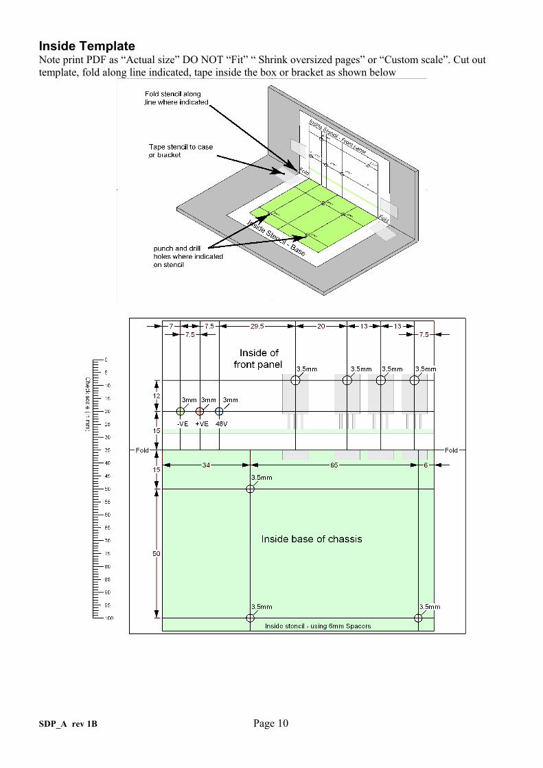
Inside TemplateNote print PDF as “Actual size” DO NOT “Fit” “ Shrink oversized pages” or “Custom scale”. Cut out template, fold along line indicated, tape inside the box or bracket as shown below
SDP_A rev 1B Page 10

Outside Template
SDP_A rev 1B Page 11