autoflow circuit balancing valves - tuvalca · 2 08.28 autoflow automatic balancing valves model ac...
TRANSCRIPT
IPS CARBON STEEL PIPE – GROOVED VALVES
. 3701 REV A
08.28
Flow Design Inc. • 8908 Governors Row, Dallas, TX 75247Phone: 1-214-631-0011 • Fax: 1-214-631-0735 • www.Flowdesign.com
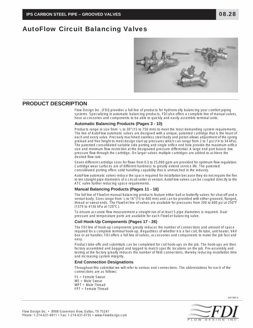
AutoFlow Circuit Balancing Valves
PRODUCT DESCRIPTION
Flow Design Inc. (FDI) provides a full line of products for hydronically balancing your comfort piping systems. Specializing in automatic balancing products, FDI also offers a complete line of manual valves, hose accessories and components to be able to quickly and easily assemble terminal units.
Automatic Balancing Products (Pages 3 - 10)
Products range in size from
1
/
2
to 30" (15 to 750 mm) to meet the most demanding system requirements. The line of AutoFlow automatic valves are designed with a unique, patented cartridge that is the heart of each and every valve. Precisely machined stainless steel body and piston allows adjustment of the spring preload and free height to meet design start up pressures which can range from 2 to 7 psi (14 to 34 kPa). The patented consolidated variable side porting and single orifice end hole provide the maximum orifice size and minimum flow restriction at the designated pressure differential. A large end port boosts low pressure flow through the cartridge. On larger valves multiple cartridges are added to achieve the desired flow rate.
Seven different cartridge sizes for flows from 0.5 to 25,000 gpm are provided for optimum flow regulation. Cartridge wear surfaces are of different hardness to greatly extend service life. The patented consolidated porting offers solid handling capability that is unmatched in the industry.
AutoFlow automatic valves reduce the space required for installation because they do not require the five to ten straight pipe diameters of a circuit setter or venturi. AutoFlow valves can be coupled directly to the ATC valve further reducing space requirements.
Manual Balancing Products (Pages 11 - 16)
The full line of FlowSet manual balancing products feature either ball or butterfly valves for shut-off and a venturi body.
Sizes range from
1
/
2
to 16" (15 to 400 mm) and can be provided with either grooved, flanged, thread or sweat ends. The FlowSet line of valves are available for pressures from 200 to 600 psi at 250°F (1379 to 4136 kPa at 120°C).
To ensure accurate flow measurement a straight run of at least 5 pipe diameters is required. Dual pressure and temperature ports are available for each FlowSet balancing valve.
Coil Hook-Up Components (Pages 17 - 26)
The FDI line of hook-up components greatly reduces the number of connections and amount of space required for a complete terminal hook-up. Regardless of whether it is a fan coil, fin tube, unit heater, VAV box or air handler, FDI offers a full line of valves, accessories and components to make the job fast and easy.
Product take-offs and submittals can be completed for coil hook-ups on the job. The hook-ups are then factory assembled and bagged and tagged to match specific locations on the job. Pre-assembly and testing at the factory greatly reduces the number of field connections, thereby reducing installation time and increasing system integrity.
End Connection Designations
Throughout this submittal we will refer to various end connections. The abbreviations for each of the connections are as follows:
FS = Female SweatMS = Male SweatMPT = Male ThreadFPT = Female Thread

2
08.28
AUTOFLOW AUTOMATIC BALANCING VALVES
Model AC
Ball Valve, Flow Regulator & Union
Model AC shown with standard Pressure/Temperature Ports
AutoFlow combination ball valve, AutoFlow regulator and union with seven (7) accessory port locations. Each unit is factory set to automatically limit the gpm to within 5% of the specified amount. The flow cartridge is removable from the valve body to provide access for gpm changes, inspection, and cleaning without breaking into the main piping.
Material Specifications
Body:
Ametal
Flow Cartridge:
Series 300 Stainless Steel Wear surfaces with Stainless Steel spring
Ball Valve:
Teflon packing, brass packing nut, plated ball, steel handle
Union:
EPDM “o” ring
Available End Connections:
MPT, FPT, MS and FS
Accuracy:
±5%
Rating:
400 psig at 250°F (2758 kPa at 120°C)
Dimensions/Weights/C
v
’s
Model
NominalSize
inches(mm)
Dimensions - inches (mm) WeightLbs. (kg) C
v
Pressure Drop†psi (kPa)
A B C D E F2-32
(14-221)5-60
(34-414)
AC0050
1
/
2
3.9 2.0 4.8 6.2 2.1 2.1 2.0 7.9 2 5
15 99 51 122 157 53 53 0,9 14 34
AC0075
3
/
4
3.9 2.0 4.8 6.2 2.1 2.1 2.1 8.8 2 5
20 99 51 122 157 53 53 1,0 14 34
AC100R* 1 3.9 2.0 4.8 6.2 2.1 2.1 2.1 8.8 2 5
25 99 51 122 157 53 53 1,0 14 34
AC0100 1 4.7 2.6 6.8 8.6 2.8 2.4 4.5 19.7 2 5
25 119 66 173 218 71 61 2,0 14 34
AC0125 1
1
/
4
4.7 2.6 6.8 8.6 2.8 2.4 4.6 20.4 2 5
32 119 66 173 218 71 61 2,1 14 34
AC0150R* 1
1
/
2
4.7 2.6 6.8 8.6 2.8 2.4 4.6 20.4 2 5
40 119 66 173 218 71 61 2,1 14 34
AC0150 1
1
/
2
5.5 3.5 7.9 10.0 3.8 2.5 9.3 52.7 2 5
40 140 89 201 254 97 64 4,2 14 34
AC0200 2 5.5 3.5 7.9 10.0 3.8 2.5 9.5 55.1 2 5
50 140 89 201 254 97 64 4,3 14 34
Dimensions based on FPT X FPT connections and will vary with mixed options/connections.All weights based on valves with Pressure/Temperature ports.All weights and dimensions are subject to minor changes.C
v
’s based on component body without flow regulator.† For pump head calculations, add the indicated AutoFlow pressure drop to calculated drops for other components.*Denotes female thread not available on union end.Dimensions not to be used for construction unless prints certified by factory.
SizeInches(mm)
PSID (kPa)Range Flow Rate – gpm (lpm)
1
/
2
–
3
/
4
15 – 20
2 – 32 0.5, 0.75, 1.0, 1.25, 1.5, 1.75, 2.0, 2.25, 2.5, 3.0, 3.5, 4.0, 4.5, 5.0, 6.0, 7.0, 8.0
14-221 1,9; 2,8; 3,8; 8,8; 5,7; 6,6; 7,6; 8,5; 9,5; 11,4; 13,2; 15,1; 17,0; 18,9; 22,7; 26,5; 30,3
5 – 60 1.0, 1.5, 2.0, 2.5, 3.0, 4.0, 5.0, 6.0, 7.0, 8.0, 9.0, 10.0, 11,0, 12.0
34-414 3,8; 5,7; 7,6; 9,5; 11,4; 13,2; 15,1; 17,0; 18,9; 22,7; 26,5; 30,3; 34,1; 37,0; 41,6; 45,4
1 – 1
1
/
4
25 – 32
2 – 32
14-221
0.5, 0.75, 1.0, 1.25, 1.5, 1.75, 2.0, 2.25, 2.5, 3.0, 3.5, 4.0, 4.5, 5.0, 6.0, 7.0, 8.0, 9.0, 10.0, 11.0, 12.0, 13.0, 14.0, 15.0, 16.0, 17.0, 18.0
1,9; 2,8; 3,8; 8,8; 5,7; 6,6; 7,6; 8,5; 9,5; 11,4; 13,2; 15,1; 17,0; 18,9; 22,7; 26,5; 30,3; 34,1; 37,0; 41,6; 45,4; 49,2; 53,0; 56,8; 60,1; 64,3; 68,1
5 – 60
34-414
1.0, 1,5, 2.0, 2.5, 3.0, 4.0, 5.0, 6.0, 7.0, 8.0, 9.0, 10.0, 11,0, 12.0, 13.0, 14.0, 15.0, 16.0, 17.0, 18.0, 19.0, 20,0, 21.0, 22.0, 23.0, 24.0, 25.0, 26.0
3,8; 5,7; 7,6; 9,5; 11,4; 13,2; 15,1; 17,0; 18,9; 22,7; 26,5; 30,3; 34,1; 37,0; 41,6; 45,4; 49,2; 53,0; 56,8; 60,1; 64,3; 68,1; 71,9; 75,7; 79,5; 83,3; 87,1; 90,8; 98,4
1
1
/
2
– 2
40 – 50
2 – 32
14-221
5.0, 6.0, 7.0, 8.0, 9.0, 10.0, 11,0, 12.0, 13.0, 14.0, 15.0, 16.0, 17.0, 18.0, 20.0, 22.0, 24.0, 26.0, 28.0, 30.0, 32.0, 34.0, 36.0, 38.0, 40.0, 42.0, 44.0, 46.0, 48.0, 50.0
18,9; 22,7; 26,5; 30,3; 34,1; 37,0; 41,6; 45,4; 49,2; 53,0; 56,8; 60,1; 64,3; 68,1; 75,7; 83,3; 90,8; 98,4; 106,0; 113,6; 121,1; 128,7; 136,3; 143,8; 151,4; 159,0; 166,5; 174,1; 181,7; 189,3
5 – 60
34-414
8.0, 9.0, 10.0, 11,0, 12.0, 13.0, 14.0, 15.0, 16.0, 17.0, 18.0, 19.0, 20.0, 21.0, 22.0, 23.0, 24.0, 25.0, 26.0, 28.0, 30.0, 32.0, 34.0, 36.0, 38.0, 40.0, 42.0, 44.0, 46.0, 48.0, 50.0, 52.0, 54.0, 56.0, 58.0, 60.0, 62.0, 64.0, 66.0, 68.0, 70.0
30,3; 34,1; 37,0; 41,6; 45,4; 49,2; 53,0; 56,8; 60,1; 64,3; 68,1; 71,9; 75,7; 79,5; 83,3; 87,1; 90,8; 98,4; 106,0; 113,6; 121,1; 128,7; 136,3; 143,8; 151,4; 159,0; 166,5; 174,1; 181,7; 189,3; 196,8; 204,4; 212,0; 219,5; 227,1; 234,7; 242,2; 249,8; 257,4; 265,0
B
D
Port1
Port2
Port 5 at 3:00Port 7 at 9:00
Port3
Port 4 at 3:00Port 6 at 9:00
A C
12:00
3:009:00
Tailpiece End View
Flow
F
E
AutoFlow Automatic Balancing Valves

08.28
3
Model MC
Ball Valve, Flow Regulator& Union
Model MC shown with standard Pressure/Temperature ports.(shown FS X FS)
Compact, T-shaped AutoFlow combination ball valve, AutoFlow regulator and union with four accessory port locations. Each unit is factory set to automatically limit the gpm to within 5% of the specified amount. The flow cartridge is removable from the valve body to provide access for gpm changes, inspection, and cleaning without breaking into the main piping.
Material Specifications
Body:
Ametal
Flow Cartridge:
Series 300 Stainless Steel Wear surfaces with Stainless Steel spring
Ball Valve:
Teflon packing, brass packing nut, plated ball, steel handle
Accuracy:
±5%
Rating:
400 psig at 250°F (2758 kPa at 120°C)
Dimensions/Weights/C
v
’s
Model
NominalSize
Inches(mm)
Dimensions - inches (mm) WeightLbs.(kg) C
v
Pressure Drop†psi (kPa) Valve Connections
A B C D E 2-32 5-60Ball Valve End
(Outlet)Union End
(Inlet)
MC0050
1
/
2
15
3.65
93
1.96
50
1.73
44
0.87
22
2.31
59
1.7
0,8
4.50 2
14
5
34
1
/
2
" FS, FPT
3
/
8
" FS
15 mm FS, FPT 10 mm FS
3
/
4
" FS, FPT
1
/
2
" FS, FPT, MPT
20 mm FS FPT 15 mm FS, FPT, MPT
FS = Female Sweat; MS = Male Sweat; MPT = Male Thread; FPT = Female ThreadDimensions based on FPT X FPT connections and will vary with mixed option/connections.All weights based on valves with Pressure/Temperature ports. Weights and dimensions are subject to minor changes.C
v
’s based on component body without flow regulator.† For pump head calculations, add the indicated AutoFlow pressure drop to calculated drops for other components.Dimensions not to be used for construction unless prints certified by factory.
SizeInches(mm)
PSID (kPa)Range Flow Rate – gpm (lpm)
1
/
2
15
2 – 32 0.5, 0.75, 1.0, 1.25, 1.5, 1.75, 2.0, 2.25, 2.5, 3.0
14-221 1,9; 2,8; 3,8; 8,8; 5,7; 6,6; 7,6; 8,5; 9,5; 11,4
5 – 60 1.0, 1,5, 2.0, 2.5, 3.0, 4.0, 5.0
34-414 3,8; 5,7; 7,6; 9,5; 11,4; 13,2; 15,1; 17,0; 18,9
Port 1
Port 3
Port 2
Port 4
Flow
Flow
Side View Top View
AutoFlow Automatic Balancing Valves

4
08.28
Model YR
Flow Regulator with Port Section
Model YR shown with standard Pressure/Temperature ports.
AutoFlow regulator, factory set to automatically limit the flow to within 5% of the specified amount. The flow cartridge is removable from the valve body to provide access for regulator changeout, inspection and cleaning without breaking into the main piping. Internal wear surfaces of the valve cartridge are stainless steel.
1
/
2
– 1" (15 – 25 mm) are available FPT X FPT or FS X FS; 1
1
/
4
– 2" (32 – 50 mm) available FPT X FPT. FS X FS available for 1
1
/
4
– 2" (32 – 50 mm) with the addition of optional brass sweat connectors.Pressure/Temperature ports are standard.
Material Specifications
Body:
Ametal
Flow Cartridge:
Series 300 Stainless Steel Wear surfaces with Stainless Steel spring
Accuracy:
±5%
Rating:
400 psig at 250°F (2758 kPa at 120°C)
Dimensions/Weights/C
v
’s
Model
NominalSize
Inches(mm) Connections
Dimensions - inches (mm) WeightLbs.(kg.) C
v
Pressure Drop†psi (kPa)
A B C D2-32
(14-221)5-60
(34-414)
YR050
1
/
2
15
FS 3.58 2.31 1.94 2.210.99
0,4
7.60 2
14
5
34
91 59 49 56
FPT 3.98 2.50 1.94 2.21
101 64 49 56
YR075
3
/
4
20
FS 3.94 2.47 1.94 2.211.04
0,5
8.70 2
14
5
34
100 63 49 56
FPT 4.17 2.63 1.94 2.21
106 67 49 56
YR100 1
25
FS 5.34 3.21 2.56 2.351.87
0,8
15.30 2
14
5
34
136 82 65 60
FPT 5.53 3.43 2.56 2.35
140 87 65 60
YR125 1
1
/
4
32
FPT 5.83 3.61 2.56 2.35 2.14 15.20 2 5
148 92 65 60 1,0 14 34
YR150 1
1
/
2
40
FPT 6.97 5.24 4.04 2.55 4.04 38.70 2 5
177 133 103 65 1,8 14 34
YR200 2
50FPT 7.05 5.51 4.04 2.55 4.49 42.10 2 5
179 140 103 65 2,0 14 34
YR250 21/265
FPT 9.06 7.01 5.18 2.94 8.00 87.20 2 5230 178 132 75 3,6 14 34
Weights based on FPT X FPT connections and will vary with mixed options/connections. All weights and dimensions are subject to minor changes.Cv’s based on component body without flow regulator.† For pump head calculations, add the indicated AutoFlow pressure drop to calculated drops for other components.Dimensions not to be used for construction unless prints certified by factory.
SizeInches(mm)
PSID (kPa)
Range Flow Rate – gpm (lpm)
1/2 – 3/415 – 20
2 – 32 0.5, 0.75, 1.0, 1.25, 1.5, 1.75, 2.0, 2.25, 2.5, 3.0, 3.5, 4.0, 4.5, 5.0, 6.0, 7.0, 8.014-221 1,9; 2,8; 3,8; 8,8; 5,7; 6,6; 7,6; 8,5; 9,5; 11,4; 13,2; 15,1; 17,0; 18,9; 22,7; 26,5; 30,3
5 – 60 1.0, 1.5, 2.0, 2.5, 3.0, 4.0, 5.0, 6.0, 7.0, 8.0, 9.0, 10.0, 11,0, 12.034-414 3,8; 5,7; 7,6; 9,5; 11,4; 13,2; 15,1; 17,0; 18,9; 22,7; 26,5; 30,3; 34,1; 37,0; 41,6; 45,4
1 – 11/425 – 32
2 – 3214-221
0.5, 0.75, 1.0, 1.25, 1.5, 1.75, 2.0, 2.25, 2.5, 3.0, 3.5, 4.0, 4.5, 5.0, 6.0, 7.0, 8.0, 9.0, 10.0, 11.0, 12.0, 13.0, 14.0, 15.0, 16.0, 17.0, 18.01,9; 2,8; 3,8; 8,8; 5,7; 6,6; 7,6; 8,5; 9,5; 11,4; 13,2; 15,1; 17,0; 18,9; 22,7; 26,5; 30,3; 34,1; 37,0; 41,6; 45,4; 49,2; 53,0; 56,8; 60,1; 64,3; 68,1
5 – 6034-414
1.0, 1,5, 2.0, 2.5, 3.0, 4.0, 5.0, 6.0, 7.0, 8.0, 9.0, 10.0, 11,0, 12.0, 13.0, 14.0, 15.0, 16.0, 17.0, 18.0, 19.0, 20,0, 21.0, 22.0, 23.0, 24.0, 25.0, 26.03,8; 5,7; 7,6; 9,5; 11,4; 13,2; 15,1; 17,0; 18,9; 22,7; 26,5; 30,3; 34,1; 37,0; 41,6; 45,4; 49,2; 53,0; 56,8; 60,1; 64,3; 68,1; 71,9; 75,7; 79,5; 83,3; 87,1; 90,8; 98,4
11/2 – 240 – 50
2 – 3214-221
5.0, 6.0, 7.0, 8.0, 9.0, 10.0, 11,0, 12.0, 13.0, 14.0, 15.0, 16.0, 17.0, 18.0, 20.0, 22.0, 24.0, 26.0, 28.0, 30.0, 32.0, 34.0, 36.0, 38.0, 40.0, 42.0, 44.0, 46.0, 48.0, 50.018,9; 22,7; 26,5; 30,3; 34,1; 37,0; 41,6; 45,4; 49,2; 53,0; 56,8; 60,1; 64,3; 68,1; 75,7; 79,5; 83,3; 90,8; 98,4; 106,0; 113,6; 121,1; 128,7; 136,3; 143,8; 151,4; 159,0; 166,5; 174,1; 181,7; 189,3
5 – 6034-414
8.0, 9.0, 10.0, 11,0, 12.0, 13.0, 14.0, 15.0, 16.0, 17.0, 18.0, 19.0, 20.0, 21.0, 22.0, 23.0, 24.0, 25.0, 26.0, 28.0, 30.0, 32.0, 34.0, 36.0, 38.0, 40.0, 42.0, 44.0, 46.0, 48.0, 50.0, 52.0, 54.0, 56.0, 58.0, 60.0, 62.0, 64.0, 66.0, 68.0, 70.030,3; 34,1; 37,0; 41,6; 45,4; 49,2; 53,0; 56,8; 60,1; 64,3; 68,1; 71,9; 75,7; 79,5; 83,3; 87,1; 90,8; 98,4; 106,0; 113,6; 121,1; 128,7; 136,3; 143,8; 151,4; 159,0; 166,5; 174,1; 181,7; 189,3; 196,8; 204,4; 212,0; 219,5; 227,1; 234,7; 242,2; 249,8; 257,4; 265,0
21/265
2 – 3214-221
9.0, 10.0, 11,0, 12.0, 13.0, 14.0, 15.0, 16.0, 17.0, 18.0, 20.0, 22.0, 24.0, 26.0, 28.0, 30.0, 32.0, 34.0, 36.0, 38.0, 40.0, 42.0, 44.0, 46.0, 48.0, 50.0, 52.0, 56.0, 60.0, 64.0, 68.0, 72.0, 76.0, 80.034,1; 37,0; 41,6; 45,4; 49,2; 53,0; 56,8; 60,1; 64,3; 68,1; 75,7; 79,5; 83,3; 90,8; 98,4; 106,0; 113,6; 121,1; 128,7; 136,3; 143,8; 151,4; 159,0; 166,5; 174,1; 181,7; 189,3;196,8; 212,0; 227,1; 242,2; 257,4; 272,5; 287,7; 302,8
5 – 6034-414
13.0, 14.0, 15.0, 16.0, 17.0, 18.0, 19.0, 20.0, 21.0, 22.0, 23.0, 24.0, 25.0, 26.0, 28.0, 30.0, 32.0, 34.0, 36.0, 38.0, 40.0, 42.0, 44.0, 46.0, 48.0, 50.0, 52.0, 54.0, 56.0, 58.0, 60.0, 62.0, 64.0, 66.0, 68.0, 70.0, 72.0, 76.0, 80.0, 84.0, 88.0, 92.0, 96.0, 100.0, 104.0, 108.0, 112.0, 116.0, 120.049,2; 53,0; 56,8; 60,1; 64,3; 68,1; 71,9; 75,7; 79,5; 83,3; 87,1; 90,8; 98,4; 106,0; 113,6; 121,1; 128,7; 136,3; 143,8; 151,4; 159,0; 166,5; 174,1; 181,7; 189,3; 196,8; 204,4; 212,0; 219,5; 227,1; 234,7; 242,2; 249,8; 257,4; 265,0; 272,5; 287,7; 302,8; 317,9; 333,1; 348,2; 363,4; 378,5; 393,6; 408,8; 423,9; 439,1; 454,2
A
Port1
Port2
Port3
Flow
B
C
D
AutoFlow Automatic Balancing Valves
08.28
5
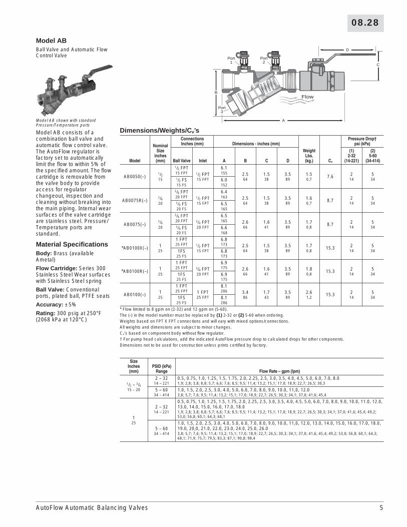
Model ABBall Valve and Automatic Flow Control Valve
Model AB shown with standard Pressure/Temperature ports
Model AB consists of a combination ball valve and automatic flow control valve. The AutoFlow regulator is factory set to automatically limit the flow to within 5% of the specified amount. The flow cartridge is removable from the valve body to provide access for regulator changeout, inspection and cleaning without breaking into the main piping. Internal wear surfaces of the valve cartridge are stainless steel. Pressure/Temperature ports are standard.
Material SpecificationsBody: Brass (available Ametal)
Flow Cartridge: Series 300 Stainless Steel Wear surfaces with Stainless Steel spring
Ball Valve: Conventional ports, plated ball, PTFE seats
Accuracy: ±5%
Rating: 300 psig at 250°F (2068 kPa at 120°C)
Dimensions/Weights/Cv’s
Model
NominalSize
inches(mm)
ConnectionsInches (mm) Dimensions - inches (mm)
WeightLbs.(kg.) Cv
Pressure Drop†psi (kPa)
Ball Valve Inlet A B C D
(1)2-32
(14-221)
(2)5-60
(34-414)
AB0050(–)1/215
1/2 FPT1/2 FPT15 FPT
6.12.564
1.538
3.589
1.50,7
7.6 214
534
15 FPT 1551/2 FS 6.015 FS 152
AB0075R(–)3/420
3/4 FPT1/2 FPT15 FPT
6.42.564
1.538
3.589
1.60,7
8.7 214
534
20 FPT 1633/4 FS 6.520 FS 165
AB0075(–)3/420
3/4 FPT3/4 FPT20 FPT
6.52.666
1.641
3.589
1.70,8
8.7 214
534
20 FPT 1653/4 FS 6.620 FS 168
*AB0100X(–) 125
1 FPT1/2 FPT15 FPT
6.82.564
1.538
3.589
1.70,8
15.3 214
534
25 FPT 173
1FS 6.825 FS 173
*AB0100R(–) 125
1 FPT3/4 FPT20 FPT
6.92.666
1.641
3.589
1.80,8
15.3 214
534
25 FPT 175
1FS 6.925 FS 175
AB0100(–) 125
1 FPT1 FPT25 FPT
8.13.486
1.743
3.589
2.61,2
15.3 214
534
25 FPT 206
1FS 8.125 FS 206
* Flow limited to 8 gpm on (2-32) and 12 gpm on (5-60).The (-) in the model number must be replaced by (1) 2-32 or (2) 5-60 when ordering.Weights based on FPT X FPT connections and will vary with mixed options/connections.All weights and dimensions are subject to minor changes.Cv’s based on component body without flow regulator.† For pump head calculations, add the indicated AutoFlow pressure drop to calculated drops for other components.Dimensions not to be used for construction unless prints certified by factory.
SizeInches(mm)
PSID (kPa)Range Flow Rate – gpm (lpm)
1/2 – 3/415 – 20
2 – 32 0.5, 0.75, 1.0, 1.25, 1.5, 1.75, 2.0, 2.25, 2.5, 3.0, 3.5, 4.0, 4.5, 5.0, 6.0, 7.0, 8.014 – 221 1,9; 2,8; 3,8; 8,8; 5,7; 6,6; 7,6; 8,5; 9,5; 11,4; 13,2; 15,1; 17,0; 18,9; 22,7; 26,5; 30,3
5 – 60 1.0, 1.5, 2.0, 2.5, 3.0, 4.0, 5.0, 6.0, 7.0, 8.0, 9.0, 10.0, 11,0, 12.034 – 414 3,8; 5,7; 7,6; 9,5; 11,4; 13,2; 15,1; 17,0; 18,9; 22,7; 26,5; 30,3; 34,1; 37,0; 41,6; 45,4
125
2 – 3214 – 221
0.5, 0.75, 1.0, 1.25, 1.5, 1.75, 2.0, 2.25, 2.5, 3.0, 3.5, 4.0, 4.5, 5.0, 6.0, 7.0, 8.0, 9.0, 10.0, 11.0, 12.0, 13.0, 14.0, 15.0, 16.0, 17.0, 18.01,9; 2,8; 3,8; 8,8; 5,7; 6,6; 7,6; 8,5; 9,5; 11,4; 13,2; 15,1; 17,0; 18,9; 22,7; 26,5; 30,3; 34,1; 37,0; 41,6; 45,4; 49,2; 53,0; 56,8; 60,1; 64,3; 68,1
5 – 6034 – 414
1.0, 1,5, 2.0, 2.5, 3.0, 4.0, 5.0, 6.0, 7.0, 8.0, 9.0, 10.0, 11,0, 12.0, 13.0, 14.0, 15.0, 16.0, 17.0, 18.0, 19.0, 20,0, 21.0, 22.0, 23.0, 24.0, 25.0, 26.03,8; 5,7; 7,6; 9,5; 11,4; 13,2; 15,1; 17,0; 18,9; 22,7; 26,5; 30,3; 34,1; 37,0; 41,6; 45,4; 49,2; 53,0; 56,8; 60,1; 64,3; 68,1; 71,9; 75,7; 79,5; 83,3; 87,1; 90,8; 98,4
A
Port1
Port2
Port3
FlowB
D
C
AutoFlow Automatic Balancing Valves

6
08.28
Model WS21/2 – 14" Flanged (Wafer Style) Automatic Flow Control Valve
Model WS shown with standard lifting lug and standard Extended Pressure/Temperature Ports
Wafer-style AutoFlow regulator factory set to automatically limit the specified flow to within ±5% over 95% of the control range. The number of flow cartridges required is determined by the gpm requested. The valve body is compatible with ANSI Class 150* or 300 lb. flanges. Extended Pressure/Temperature Ports, lifting lug, drain plug, flange rods and nuts are standard. Pressure/temperature port options are limited to a quantity of three (2 at 12:00 and 1 at 6:00) and are shipped loose for field installation. Companion flanges and gaskets are not included.*Class 150 only for 16 - 30" sizes.
Material SpecificationsBody: Ductile iron
Flow Cartridge: Series 300 Stainless Steel Wear surfaces with Stainless Steel spring
Rating: 600 psig at 250°F (4136 kPa at 120°C)
Dimensions
Model
NominalSize
Inches(mm)
Dimensions - inches (mm)
WeightLbs.(kg.)
Max. No. of
Cartridges
Maximum gpm (lps)*Control Range psi (kPa)
A B C
(1)2-32
(14-221)
(2)5-60
(34-414)
(3)3-20
(21-138)
(4)5-40
(34-276)
(5)7-45
(48-310)
WS0250(-) 21/2 4.3 3.0 5.8 16.0 1 80 120 – – –65 109 76 147 7,3 5,0 7,6
WS0300(-) 3 5.0 3.3 8.8 24.0 1 135 170 200 250 30080 127 84 224 10,9 8,5 10,7 12,6 15,8 18,9
WS0400(-) 4 6.8 4.6 9.6 42.0 2 270 340 400 500 600100 173 117 244 19,1 17,0 21,5 25,2‘ 31,6 37,9
WS0500(-) 5 7.6 5.7 10.0 56.0 3 405 510 600 750 900125 193 145 254 25,4 25,6 32,2 37,9 47,3 56,8
WS0600(-) 6 8.6 6.7 10.2 67.0 4 540 680 800 1000 1200150 218 170 259 30,4 34,1 42,9 50,5 63,1 75,7
WS0800(-) 8 10.9 8.7 11.0 93.0 7 945 1190 1400 1750 2100200 277 215 279 42,2 59,6 75,1 88,3 110,4 132,5
WS1000(-) 10 13.3 10.9 8.8 82.0 11 1485 1870 2200 2750 3300250 338 277 224 37,2 93,7 118,0 138,8 173,5 208,2
WS1200(-) 12 16.1 12.6 8.8 113.0 15 2025 2550 3000 3750 4500300 409 320 224 51,3 127,8 160,9 189,3 236,6 284,0
WS1400(-) 14 17.8 14.1 8.8 141.0 19 2565 3230 3800 4750 5700350 452 358 224 64,0 161,9 203,8 239,8 299,7 359,7
WS1600(-) 16 17.0 20.0 15.3 550.0 23 3105 3910 4600 5750 6900400 430 510 390 250 195,9 246,7 290,3 362,8 435,4
WS1800(-) 18 17.5 21.5 17.3 620.0 28 3780 4670 5600 7000 8400450 430 545 390 280 238,5 300,4 353,4 441,7 530,0
WS2000(-) 20 19.0 23.6 19.3 690.0 32 4320 5440 6400 8000 9600500 480 600 490 315 272,6 343,3 403,8 504,8 605,8
WS2400(-) 24 21.3 26.9 23.3 950.0 45 6075 7650 9000 11250 13500600 540 585 590 430 383,3 432,7 567,9 709,9 851,9
WS3000(-) 30 22.8 34.5 29.3 1400.0 70 9450 11900 14000 17500 21000750 580 875 745 635 596,3 750,9 883,4 1104,3 1325,1
The (-) in the model number must be replaced by 1: 2-32 (14-221); 2: 5-60 (34-414); 3:3-20 (21-138); 4:5-40 (35-276); or 5:7-45 (48-310) when ordering.For pump head calculations, the following loss applies for each range: 4.6 ft./460 Pa/m (2-32); 11.6 ft./1160 Pa/m (5-60); 6.9 ft./690 Pa/m (3-20); 11.6 ft./1160 Pa/m (5-40); and 16.2 ft./1620 Pa/m (7-45).* gpm increments are 5 gpm for 2-32 and 5-60, 10 gpm for 3-20 and 5-40 and 20 gpm for 7-45.All weights and dimensions are subject to minor changes. Flange bolts and nuts not included in estimated weight.Lifting lug provided on valves 6" and above.
A B
C
PORT 1FDI supplies long bolts& nuts with each unit PORT 2
PORT 3150 or 300 lb. flangessupplied by customer
Flow
Flow
AutoFlow Automatic Balancing Valves
08.28
7
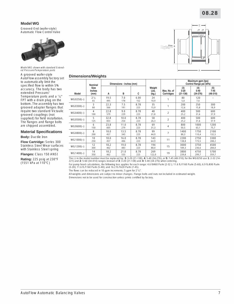
Model WGGrooved-End (wafer-style) Automatic Flow Control Valve
Model WG shown with standard Extend-ed Pressure/Temperature ports
A grooved wafer-style AutoFlow assembly factory set to automatically limit the specified flow to within 5% accuracy. The body has two extended Pressure/Temperature ports and a 1/2" FPT with a drain plug on the bottom. The assembly has two grooved adapter flanges that require two standard Victaulic grooved couplings (not supplied) for field installation. The flanges and flange bolts are shipped assembled.
Material SpecificationsBody: Ductile Iron
Flow Cartridge: Series 300 Stainless Steel Wear surfaces with Stainless Steel spring
Flanges: Class 150 ANSI
Rating: 225 psig at 230°F (1551 kPa at 110°C)
Dimensions/Weights
Model
NominalSize
Inches(mm)
Dimensions - inches (mm)
WeightLbs.(kg.)
Max. No. of Cartridges
Maximum gpm (lps)Control Range psi (kPa)
A B C
(3)3-20
(21-138)
(4)5-40
(34-276)
(5)7-45
(48-310)
WG0250(–) 21/2 19.5 7.0 6.00 24 1 80 120 –65 495 178 152 10,9 5,0 7,6
WG0300(–) 3 22.3 7.5 8.78 35 1 200 250 30080 566 191 223 15,9 12,6 15,8 18,9
WG0400(–) 4 22.8 9.0 8.78 48 2 400 500 600100 579 229 223 21,8 25,2 31,6 37,9
WG0500(–) 5 32.8 10.0 8.78 58 2 400 500 600125 833 254 223 26,3 25,2 31,6 37.9
WG0600(–) 6 23.8 11.0 8.78 69 4 800 1000 1200150 605 279 223 31,3 50,5 63,1 75,7
WG0800(–) 8 18.0 13.5 8.78 99 7 1400 1750 2100200 457 343 223 44,9 88,3 110,4 132,5
WG1000(–) 10 18.0 16.0 8.78 143 11 2200 2750 3300250 457 406 223 64,9 138,8 173,5 208,2
WG1200(–) 12 18.2 19.0 8.78 194 15 3000 3750 4500300 462 483 223 88,0 189,3 236,6 284,0
WG1400(–) 14 18.2 21.0 8.78 269 19 3800 4750 5700350 462 533 223 122,0 239,8 299,7 359,7
The (-) in the model number must be replaced by: 3: 3-20 (21-138), 4: 5-40 (34-276), or 5: 7-45 (48-310); for the WG0250 use 1: 2-32 (14-221) and 2: 5-60 (34-414) ranges instead of 3: 3-20 (21-138) and 4: 5-40 (34-276) when ordering.For pump head calculations, the following loss applies for each range: 4.6 ft/460 Pa/m (2-32 ); 11.6 ft./1160 Pa/m (5-60); 6.9 ft./690 Pa/m (3-20); 11.6 ft./1160 Pa/m (5-40); and 16.2 ft./1620 Pa/m (7-45).The flows can be reduced in 10 gpm increments; 5 gpm for 21/2".All weights and dimensions are subject to minor changes. Flange bolts and nuts not included in estimated weight.Dimensions not to be used for construction unless prints certified by factory.
A
C
BFlow
AutoFlow Automatic Balancing Valves
8
08.28
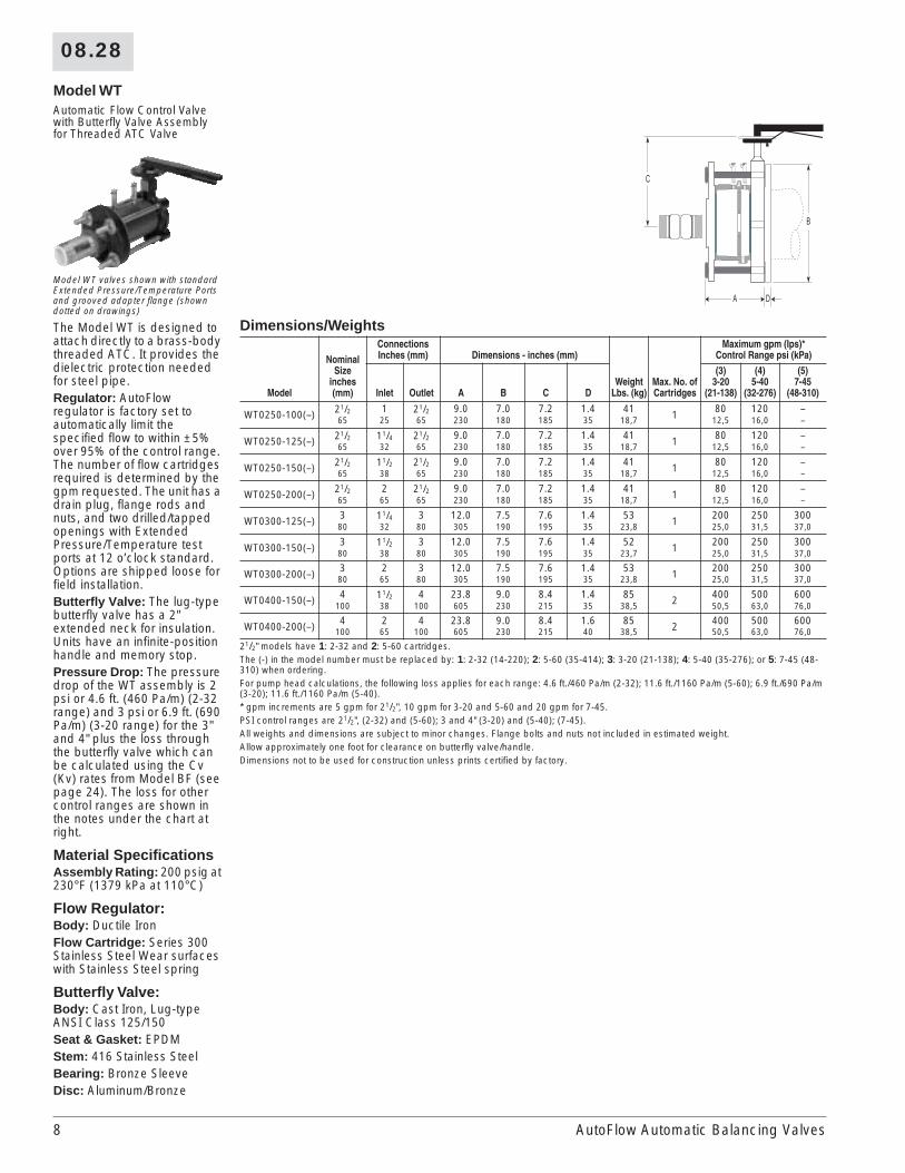
Model WTAutomatic Flow Control Valve with Butterfly Valve Assembly for Threaded ATC Valve
Model WT valves shown with standard Extended Pressure/Temperature Ports and grooved adapter flange (shown dotted on drawings)
The Model WT is designed to attach directly to a brass-body threaded ATC. It provides the dielectric protection needed for steel pipe.Regulator: AutoFlow regulator is factory set to automatically limit the specified flow to within ±5% over 95% of the control range. The number of flow cartridges required is determined by the gpm requested. The unit has a drain plug, flange rods and nuts, and two drilled/tapped openings with Extended Pressure/Temperature test ports at 12 o’clock standard. Options are shipped loose for field installation.Butterfly Valve: The lug-type butterfly valve has a 2" extended neck for insulation. Units have an infinite-position handle and memory stop.Pressure Drop: The pressure drop of the WT assembly is 2 psi or 4.6 ft. (460 Pa/m) (2-32 range) and 3 psi or 6.9 ft. (690 Pa/m) (3-20 range) for the 3" and 4" plus the loss through the butterfly valve which can be calculated using the Cv (Kv) rates from Model BF (see page 24). The loss for other control ranges are shown in the notes under the chart at right.
Material SpecificationsAssembly Rating: 200 psig at 230°F (1379 kPa at 110°C)
Flow Regulator:Body: Ductile IronFlow Cartridge: Series 300 Stainless Steel Wear surfaces with Stainless Steel spring
Butterfly Valve:Body: Cast Iron, Lug-type ANSI Class 125/150Seat & Gasket: EPDMStem: 416 Stainless SteelBearing: Bronze SleeveDisc: Aluminum/Bronze
Dimensions/Weights
Model
NominalSize
inches(mm)
ConnectionsInches (mm) Dimensions - inches (mm)
WeightLbs. (kg)
Max. No. of Cartridges
Maximum gpm (Ips)*Control Range psi (kPa)
Inlet Outlet A B C D
(3)3-20
(21-138)
(4)5-40
(32-276)
(5)7-45
(48-310)
WT0250-100(–) 21/2 1 21/2 9.0 7.0 7.2 1.4 41 1 80 120 –65 25 65 230 180 185 35 18,7 12,5 16,0 –
WT0250-125(–) 21/2 11/4 21/2 9.0 7.0 7.2 1.4 41 1 80 120 –65 32 65 230 180 185 35 18,7 12,5 16,0 –
WT0250-150(–) 21/2 11/2 21/2 9.0 7.0 7.2 1.4 41 1 80 120 –65 38 65 230 180 185 35 18,7 12,5 16,0 –
WT0250-200(–) 21/2 2 21/2 9.0 7.0 7.2 1.4 41 1 80 120 –65 65 65 230 180 185 35 18,7 12,5 16,0 –
WT0300-125(–) 3 11/4 3 12.0 7.5 7.6 1.4 53 1 200 250 30080 32 80 305 190 195 35 23,8 25,0 31,5 37,0
WT0300-150(–) 3 11/2 3 12.0 7.5 7.6 1.4 52 1 200 250 30080 38 80 305 190 195 35 23,7 25,0 31,5 37,0
WT0300-200(–) 3 2 3 12.0 7.5 7.6 1.4 53 1 200 250 30080 65 80 305 190 195 35 23,8 25,0 31,5 37,0
WT0400-150(–) 4 11/2 4 23.8 9.0 8.4 1.4 85 2 400 500 600100 38 100 605 230 215 35 38,5 50,5 63,0 76,0
WT0400-200(–) 4 2 4 23.8 9.0 8.4 1.6 85 2 400 500 600100 65 100 605 230 215 40 38,5 50,5 63,0 76,0
21/2" models have 1: 2-32 and 2: 5-60 cartridges.The (-) in the model number must be replaced by: 1: 2-32 (14-220); 2: 5-60 (35-414); 3: 3-20 (21-138); 4: 5-40 (35-276); or 5: 7-45 (48-310) when ordering.For pump head calculations, the following loss applies for each range: 4.6 ft./460 Pa/m (2-32); 11.6 ft./1160 Pa/m (5-60); 6.9 ft./690 Pa/m (3-20); 11.6 ft./1160 Pa/m (5-40).* gpm increments are 5 gpm for 21/2", 10 gpm for 3-20 and 5-60 and 20 gpm for 7-45.PSI control ranges are 21/2", (2-32) and (5-60); 3 and 4" (3-20) and (5-40); (7-45).All weights and dimensions are subject to minor changes. Flange bolts and nuts not included in estimated weight.Allow approximately one foot for clearance on butterfly valve/handle.Dimensions not to be used for construction unless prints certified by factory.
B
A D
C
AutoFlow Automatic Balancing Valves

08.28
9
Model WBFlow Regulator with Butterfly ValveModel WB shown with standard Extend-ed Pressure/Temperature Ports and optional mating flange (in dotted lines).
Regulator: Wafer-style AutoFlow regulator factory set to automatically limit the specified flow to within ±5% over 95% of the control range. The number of flow cartridges required is determined by the gpm requested. The regulator body is compatible ANSI Class 150 or 300 lb. flanges. Extended Pressure/Temperature ports, lifting lug, drain plug, flange rods and nuts are standard. Pressure-temperature port options are limited to a quantity of three (2 at 12:00 and 1 at 6:00) and are shipped loose for field installation. Companion flanges/gaskets not included.
Butterfly Valve: The lug-type butterfly valve has a 2" (50 mm) extended neck for insulation. Units have an infinite-position handle 21/2 – 8” (65 – 200 mm).
Pressure Drop: The pressure drop of the WB assembly is 2 psi or 4.6 ft. (460 Pa/m) (2-32 range) plus the loss through the butterfly valve which can be calculated using the Cv (Kv) rates on the BF Model (see page 24). The loss for other control ranges are shown in the notes under the chart below.
Material SpecificationsAssembly Rating: 240 psig at 230°F (1655 kPa at 110°C)
Flow Regulator:Body: Ductile IronFlow Cartridge: Series 300 Stainless Steel Wear surfaces with Stainless Steel spring
Butterfly Valve:Body: Cast Iron, Lug-type ANSI Class 125/150Seat & Gasket: EPDMStem: 416 Stainless SteelBearing: Bronze SleeveDisc: Aluminum/Bronze
Dimensions/Weights
Model
NominalSize
inches(mm)
Dimensions - inches (mm)
WeightLbs. (kg)
Max. No. of Cartridges
Maximum gpm (lps)*Control Range psi (kPa)
A B C
(1)2-32
(14-221)
(2)5-60
(34-414)
(3)3-20
(21-138)
(4)5-40
(34-276)
(5)7-45
(48-310)
WB0250(–) 21/2 7.5 7.0 7.2 30 1 80 120 – – –65 190 180 185 13,5 5,0 8,0 – – –
WB0300(–) 3 10.6 7.5 7.6 40 1 135 170 200 250 30080 255 190 195 18,0 8,5 11,0 12,5 16,0 19,0
WB0400(–) 4 11.7 9.0 8.4 66 2 270 340 400 500 600100 295 230 215 29,9 17,0 21,5 25,0 31,5 37,0
WB0500(–) 5 12.3 10.0 8.9 86 3 405 510 600 750 900125 315 255 225 39,2 25,5 32,0 38,0 47,0 57,0
WB0600(–) 6 12.4 11.0 9.6 103 4 540 680 800 1000 1200150 315 280 245 46,7 34,0 43,0 50,5 63,0 76,0
WB0800(–) 8 13.4 13.5 10.8 151 7 945 1190 1400 1750 2100200 340 345 275 68,6 60,0 75,0 88,5 110,0 132,5
The (-) in the model number must be replaced by: 1: 2-32 (14-220); 2: 5-60 (35-414); 3: 3-20 (21-138); 4: 5-40 (35-276); or 5:7-45 (48-310) when ordering.For pump head calculations, the following loss applies for each range: 4.6 ft./460 Pa/m (2-32); 11.6 ft./1160 Pa/m (5-60); 6.9 ft./690 Pa/m (3-20); 11.6 ft./1160 Pa/m (5-40).* gpm increments are 5 gpm for 2-32 and 5-60, 10 gpm for 3-20 and 5-40 and 20 gpm for 7-45.All weights and dimensions are subject to minor changes. Flange bolts and nuts not included in estimated weight.Allow approximately one foot for clearance on butterfly valve/handle.Dimensions not to be used for construction unless prints certified by factory.
Flow
A
C
B
AutoFlow Automatic Balancing Valves

10
08.28
Model WRAutomatic Flow Control Valve with Butterfly Valve and Flanged Reducer
Model WR shown with standard Extend-ed Pressure/Temperature Ports
Regulator: the AutoFlow assembly is designed to attach directly to flanged ATC valves which are smaller than runout size. The regulator is factory set to automatically limit the specified flow to within ±5% accuracy. The flanged reducer, flow regulator and butterfly valve are shipped assembled. The maximum gpm flows for each size are shown in the table to the right. Ten gpm reduced increments are available (i.e. 3"/80 mm (3-20) control range is available 200, 190, 180, 170, etc.). Extended Pressure/Temperature ports are standard.Butterfly Valve: The lug-type butterfly valve has a 2"/50 mm extended neck for insulation. Units have an infinite-position handle and memory stop.Pressure Drop: The pressure drop of the WR assembly is 3 psi or 6.9 ft./690 Pa/m (3-20 range) plus the loss through the butterfly valve which can be calculated using the Cv/Kv rates on the BF model (see page 24). The loss for other control ranges are shown in the notes under the chart to the right.
Material SpecificationsAssembly Rating: 225 psig at 230°F (1551 kPa at 110°C)
Flow Regulator:Body: Ductile IronFlow Cartridge: Series 300 Stainless Steel Wear surfaces with Stainless Steel spring
Butterfly Valve:Body: Cast Iron, Lug-type ANSI Class 125/150Seat & Gasket: EPDMStem: 416 Stainless SteelBearings: Bronze SleeveDisc: Aluminum/BronzeFlanged Reducer: ANSI Class 150 lb. Forged Steel
Dimensions/Weights
Model
NominalSize
inches(mm)
ConnectionsInches (mm) Dimensions - inches (mm)
WeightLbs. (kg)
Max. No. of Cartridges
Maximum gpm (Ips)*Control Range psi (kPa)
Inlet Outlet A B C D
(3)3-20
(21-138)
(4)5-40
(32-276)
(5)7-45
(48-310)
WR0300-250(–) 3 21/2 3 20.7 7.5 7.6 1.4 61 1 200 250 30080 65 80 525 190 195 35 27,6 12,5 16,0 19,0
WR0400-250(–) 4 21/2 4 21.8 9.0 8.4 1.6 93 2 400 500 600100 65 100 555 230 215 40 42,0 25,0 31,5 37,0
WR0400-300(–) 4 3 4 21.9 9.0 8.4 1.6 94 2 400 500 600100 80 100 555 230 215 40 42,7 25,0 31,5 37,0
WR0600-300(–) 6 3 6 24.1 11.0 9.6 1.8 140 4 800 1000 1200150 80 150 610 280 245 45 63,4 50,5 63,0 76,0
WR0600-400(–) 6 4 6 24.2 11.0 9.6 1.8 145 4 800 1000 1200150 100 150 615 280 245 45 65,9 50,5 63,0 76,0
WR0600-500(–) 6 4 6 24.4 11.0 9.6 1.8 146 4 800 1000 1200150 100 150 620 280 245 45 66,3 50,5 63,0 76,0
The (-) in the model number must be replaced by: 3: 3-20 (21-138); 4: 5-40 (35-276); or 5: 7-45 (48-310) when ordering.For pump head calculations, the following loss applies for each range: 6.9 ft./690 Pa/m (3-20); 11.6 ft./1160 Pa/m (5-40); and 16.2 ft./1620 Pa/m (7-45).* All models can have reduced flows in 10 gpm increments.All weights and dimensions are subject to minor changes.Allow approximately one foot for clearance on butterfly valve/handle.Dimensions not to be used for construction unless prints certified by factory.
Flow
A D
C
B
WR drawing shows optional grooved adapter flange (dotted lines)
AutoFlow Automatic Balancing Valves
08.28
11
MANUAL BALANCING VALVES
C
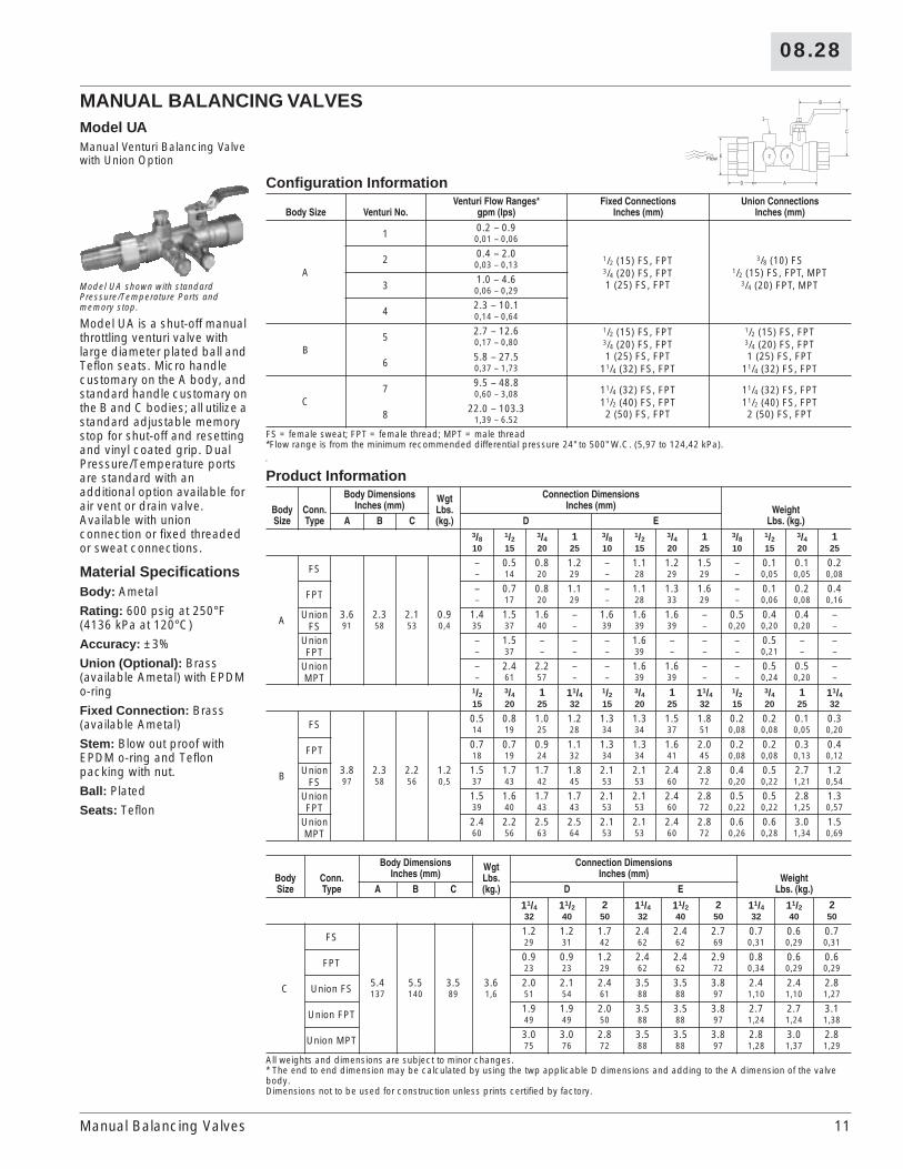
Model UAManual Venturi Balancing Valve with Union Option
Model UA shown with standard Pressure/Temperature Ports and memory stop.
Model UA is a shut-off manual throttling venturi valve with large diameter plated ball and Teflon seats. Micro handle customary on the A body, and standard handle customary on the B and C bodies; all utilize a standard adjustable memory stop for shut-off and resetting and vinyl coated grip. Dual Pressure/Temperature ports are standard with an additional option available for air vent or drain valve. Available with union connection or fixed threaded or sweat connections.
Material SpecificationsBody: Ametal
Rating: 600 psig at 250°F (4136 kPa at 120°C)
Accuracy: ±3%
Union (Optional): Brass (available Ametal) with EPDM o-ring
Fixed Connection: Brass (available Ametal)
Stem: Blow out proof with EPDM o-ring and Teflon packing with nut.
Ball: Plated
Seats: Teflon
Configuration Information
Body Size Venturi No.Venturi Flow Ranges*
gpm (lps)Fixed Connections
Inches (mm)Union Connections
Inches (mm)
A
1 0.2 – 0.9
1/2 (15) FS, FPT3/4 (20) FS, FPT1 (25) FS, FPT
3/8 (10) FS1/2 (15) FS, FPT, MPT
3/4 (20) FPT, MPT
0,01 – 0,06
2 0.4 – 2.00,03 – 0,13
3 1.0 – 4.60,06 – 0,29
4 2.3 – 10.10,14 – 0,64
B5 2.7 – 12.6 1/2 (15) FS, FPT
3/4 (20) FS, FPT1 (25) FS, FPT
11/4 (32) FS, FPT
1/2 (15) FS, FPT3/4 (20) FS, FPT1 (25) FS, FPT
11/4 (32) FS, FPT
0,17 – 0,80
6 5.8 – 27.50,37 – 1,73
C7 9.5 – 48.8
11/4 (32) FS, FPT11/2 (40) FS, FPT2 (50) FS, FPT
11/4 (32) FS, FPT11/2 (40) FS, FPT2 (50) FS, FPT
0,60 – 3,08
8 22.0 – 103.31,39 – 6.52
FS = female sweat; FPT = female thread; MPT = male thread*Flow range is from the minimum recommended differential pressure 24" to 500" W.C. (5,97 to 124,42 kPa).
Product Information
Body Size
Conn. Type
Body DimensionsInches (mm)
WgtLbs.(kg.)
Connection DimensionsInches (mm) Weight
Lbs. (kg.)A B C D E3/8 1/2 3/4 1 3/8 1/2 3/4 1 3/8 1/2 3/4 110 15 20 25 10 15 20 25 10 15 20 25
A
FS – 0.5 0.8 1.2 – 1.1 1.2 1.5 – 0.1 0.1 0.2– 14 20 29 – 28 29 29 – 0,05 0,05 0,08
FPT – 0.7 0.8 1.1 – 1.1 1.3 1.6 – 0.1 0.2 0.4– 17 20 29 – 28 33 29 – 0,06 0,08 0,16
Union FS
3.6 2.3 2.1 0.9 1.4 1.5 1.6 – 1.6 1.6 1.6 – 0.5 0.4 0.4 –91 58 53 0,4 35 37 40 – 39 39 39 – 0,20 0,20 0,20 –
Union FPT
– 1.5 – – – 1.6 – – – 0.5 – –– 37 – – – 39 – – – 0,21 – –
Union MPT
– 2.4 2.2 – – 1.6 1.6 – – 0.5 0.5 –– 61 57 – – 39 39 – – 0,24 0,20 –
1/2 3/4 1 11/4 1/2 3/4 1 11/4 1/2 3/4 1 11/415 20 25 32 15 20 25 32 15 20 25 32
B
FS 0.5 0.8 1.0 1.2 1.3 1.3 1.5 1.8 0.2 0.2 0.1 0.314 19 25 28 34 34 37 51 0,08 0,08 0,05 0,20
FPT 0.7 0.7 0.9 1.1 1.3 1.3 1.6 2.0 0.2 0.2 0.3 0.418 19 24 32 34 34 41 45 0,08 0,08 0,13 0,12
Union FS
3.8 2.3 2.2 1.2 1.5 1.7 1.7 1.8 2.1 2.1 2.4 2.8 0.4 0.5 2.7 1.297 58 56 0,5 37 43 42 45 53 53 60 72 0,20 0,22 1,21 0,54
Union FPT
1.5 1.6 1.7 1.7 2.1 2.1 2.4 2.8 0.5 0.5 2.8 1.339 40 43 43 53 53 60 72 0,22 0,22 1,25 0,57
Union MPT
2.4 2.2 2.5 2.5 2.1 2.1 2.4 2.8 0.6 0.6 3.0 1.560 56 63 64 53 53 60 72 0,26 0,28 1,34 0,69
Body Size
Conn. Type
Body DimensionsInches (mm)
WgtLbs.(kg.)
Connection DimensionsInches (mm) Weight
Lbs. (kg.)A B C D E
11/4 11/2 2 11/4 11/2 2 11/4 11/2 232 40 50 32 40 50 32 40 50
C
FS 1.2 1.2 1.7 2.4 2.4 2.7 0.7 0.6 0.729 31 42 62 62 69 0,31 0,29 0,31
FPT 0.9 0.9 1.2 2.4 2.4 2.9 0.8 0.6 0.623 23 29 62 62 72 0,34 0,29 0,29
Union FS 5.4 5.5 3.5 3.6 2.0 2.1 2.4 3.5 3.5 3.8 2.4 2.4 2.8137 140 89 1,6 51 54 61 88 88 97 1,10 1,10 1,27
Union FPT 1.9 1.9 2.0 3.5 3.5 3.8 2.7 2.7 3.149 49 50 88 88 97 1,24 1,24 1,38
Union MPT 3.0 3.0 2.8 3.5 3.5 3.8 2.8 3.0 2.875 76 72 88 88 97 1,28 1,37 1,29
All weights and dimensions are subject to minor changes.* The end to end dimension may be calculated by using the twp applicable D dimensions and adding to the A dimension of the valve body. Dimensions not to be used for construction unless prints certified by factory.
E
C
B
D A
2
1
3Flow
Manual Balancing Valves

12
08.28
Models VG, VFSteel Venturi
Material SpecificationsBody: Carbon Steel ASTM A-53; Carbon Steel Insert
VG Rating: 400 psig at 230°F (2758 kPa at 110°C)
VF Rating: 240 psig at 230°F (1655 kPa at 110°C)
Design: Throat Signal – Piezo-ring; 120° 3-port averaging
Flange: Standard Flange class 150, ANSI B16.5 (300/600 class available)
Instrument Valves: Pressure/Temperature Ports; Extended P/T ports standard on Model VF
B
A
C
Flow
Model VG Grooved End
B
A
C
Flow
Model VF Flanged
Dimensions/Weights
ModelNominal SizeInches (mm) Connections
Dimensions – Inches (mm) WeightLbs. (kg.)A B C
VG0200(*) 2 Grooved End 8.4 2.38 2.44 2.650 213 60 62 1,2
VF0200(*) 2 Flanged End 6.4 6.00 3.00 11.650 163 152 76 5,3
VG0250(*) 21/2 Grooved End 8.4 2.88 2.69 4.165 213 73 68 1,9
VF0250(*) 21/2 Flanged End 6.4 7.00 3.50 18.665 163 178 89 8,4
VG0300(*) 3 Grooved End 8.0 3.50 3.00 5.080 203 89 76 2,3
VF0300(*) 3 Flanged End 9.0 7.50 3.75 23.080 229 191 95 10,4
VG0400(*) 4 Grooved End 10.8 4.50 3.50 9.7100 274 114 89 4,4
VF0400(*) 4 Flanged End 11.8 9.00 4.50 33.7100 300 229 114 15,3
VG0500(*) 5 Grooved End 11.3 5.56 4.03 13.7125 287 141 102 6,2
VF0500(*) 5 Flanged End 12.3 10.00 5.00 39,7125 312 254 127 18,0
VG0600(*) 6 Grooved End 11.8 6.63 4.56 18.6150 300 168 116 8,4
VF0600(*) 6 Flanged End 12.8 11.00 5.50 54.6150 325 279 140 24,8
VG0800(*) 8 Grooved End 12.5 8.63 5.56 29.7200 318 219 141 13,5
VF0800(*) 8 Flanged End 13.5 13.50 6.75 85.7200 343 343 17 38,9
VG1000(*) 10 Grooved End 13.5 10.75 6.63 45.5250 343 273 168 20,6
VF1000(*) 10 Flanged End 14.5 16.00 8.00 117.5250 368 406 203 53,3
VG1200(*) 12 Grooved End 15.3 12.75 7.63 63.0300 389 324 194 28,6
VF1200(*) 12 Flanged End 16.3 19.00 9.50 183.0300 414 483 241 83,0
VG1400(*) 14 Grooved End 17.0 14.00 8.25 77.9350 432 356 210 35,3
VF1400(*) 14 Flanged End 18.0 21.00 10.50 231.9350 457 533 267 105,2
VG1600L 16 Grooved End 17.5 16.00 9.25 91.9400 445 406 235 41,7
VF1600L 16 Flanged End 18.5 23.50 11.75 299.9400 470 597 298 136,0
(*) denotes L (low flow) or H (high flow). The 2 – 14" products are available in low and high beta ratios. The 16" product is available in low beta only. All weights and dimensions are subject to change.Venturi products made from fabricated materials may vary ±1/16 inch per component. Dimensions to to be used for construction unless prints certified by factory.
Manual Balancing Valves

08.28
13
Model AG/AF2 – 16" (50 – 400 mm) Steel AccuSetter Venturi with Butterfly Balance Valve
Model AG shown with standard Extend-ed Pressure/Temperature ports
The AccuSetter uses a low-loss venturi to obtain a measurement accuracy of ±3%. The valve handle has an infinite-position memory stop for sizes 2 – 6" (50 – 150 mm) and a gear operator on 8 – 16" (200 – 400 mm) sizes. Flow measurement can be obtained with a differential pressure meter reading across the venturi taps. The design flow can be obtained by adjusting the valve operator until the desired gpm is reached. The set handle position is maintained by using the memory stop.Model AG: Model AG AccuSetter includes a grooved venturi on the entry with a lug butterfly valve mounted on the downstream exit and a Model GF 150# grooved adapter flange with cap screws, supplied loose, for attachment to the butterfly valve and downstream grooved pipe.Model AF: Model AF AccuSetter includes a flanged venturi with a lug butterfly valve attached to the downstream side.
Material SpecificationsRating: 240 psi at 230°F (1655 kPa at 110°C)Accuracy: ±3%
Venturi:Body: Steel ASTM A-53Instrument Valves: Extended Pressure/Temperature Test PortsDesign: Low loss, piezo-ring throat
Butterfly Valve:Body: Cast Iron, Lug-type ANSI Class 125/150Seat & Gasket: EPDMStem: 416 Stainless SteelBearings: Bronze SleeveDisc: Aluminum/Bronze
Dimensions/Weights
ModelNominal SizeInches (mm) Connections
Dimensions – Inches (mm) WeightLbs. (kg.)A B C D
AG0200(*) 2 Grooved 10.5 6.0 6.6 0.8 19.350 267 152 168 20 8,8
AF0200(*) 2 150# Flanged 8.3 6.0 6.6 0.8 20.650 211 152 168 20 9,3
AG0250(*) 21/2 Grooved 10.7 7.0 7.2 0.9 25.265 272 178 183 23 11,4
AF0250(*) 21/2 150# Flanged 8.3 7.0 7.2 0.9 27.665 211 178 183 23 12,5
AG0300(*) 3 Grooved 11.3 7.5 7.6 1.0 31.680 287 191 193 25 14,3
AF0300(*) 3 150# Flanged 10.9 7.5 7.6 1.0 35.080 277 191 193 25 15,9
AG0400(*) 4 Grooved 14.3 9.0 8.4 1.0 49.5100 363 229 213 25 22,5
AF0400(*) 4 150# Flanged 13.9 9.0 8.4 1.0 53.7100 353 229 213 25 24,4
AG0500(*) 5 Grooved 14.9 10.0 9.0 1.0 61.3125 378 254 229 25 27,8
AF0500(*) 5 150# Flanged 14.5 10.0 9.0 1.0 64.7125 368 254 229 25 29,3
AG0600(*) 6 Grooved 15.6 11.0 9.7 1.0 78.6150 396 279 246 25 35,7
AF0600(*) 6 150# Flanged 15.1 11.0 9.7 1.0 86.6150 387 279 246 25 39,3
AG0800(*) 8 Grooved 16.6 13.5 7.5 1.2 123.3200 422 343 191 30 55,9
AF0800(*) 8 150# Flanged 16.0 13.5 7.5 1.2 135.7200 406 343 191 30 61,6
AG1000(*) 10 Grooved 18.1 16.0 7.5 1.2 178.3250 460 406 191 30 80,9
AF1000(*) 10 150# Flanged 17.4 16.0 7.5 1.2 194.5250 442 406 191 30 88,2
AG1200(*) 12 Grooved 20.3 19.0 7.5 1.3 279.6300 516 483 191 33 126,8
AF1200(*) 12 150# Flanged 19.5 19.0 7.5 1.3 307.0300 495 483 191 33 139,3
AG1400(*) 14 Grooved 26.9 21.0 11.8 1.5 399.3350 683 533 300 38 181,1
AF1400(*) 14 150# Flanged 21.6 21.0 11.8 1.5 372.9350 549 533 300 38 169,1
AG1600L 16 Grooved 27.8 16.0 11.8 1.5 550.9400 706 406 300 38 249,9
AF1600L 16 150# Flanged 22.5 23.5 11.8 1.5 539.9400 572 597 300 38 244,9
* Denotes L (low flow) or H (high flow). Flow rate must be specified when ordering.All weights and dimensions are subject to change.Venturi products made from fabricated materials may vary ± 1/16 inch per component.Dimensions not to be used for construction unless prints certified by factory.
B
C
A D
FlowB
C
A D
Flow
Model AG Model AF
Manual Balancing Valves
14
08.28
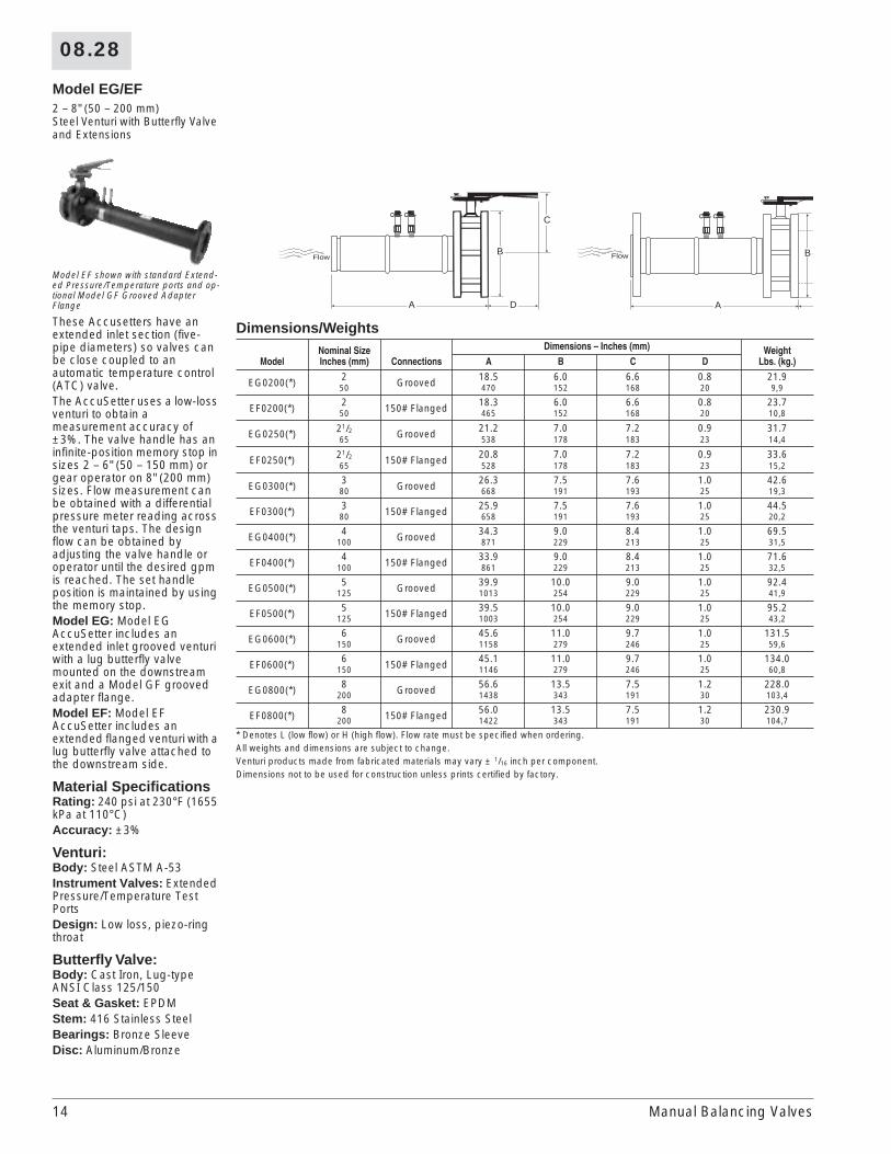
Model EG/EF2 – 8" (50 – 200 mm) Steel Venturi with Butterfly Valve and Extensions
Model EF shown with standard Extend-ed Pressure/Temperature ports and op-tional Model GF Grooved Adapter Flange
These Accusetters have an extended inlet section (five-pipe diameters) so valves can be close coupled to an automatic temperature control (ATC) valve.The AccuSetter uses a low-loss venturi to obtain a measurement accuracy of ±3%. The valve handle has an infinite-position memory stop in sizes 2 – 6" (50 – 150 mm) or gear operator on 8" (200 mm) sizes. Flow measurement can be obtained with a differential pressure meter reading across the venturi taps. The design flow can be obtained by adjusting the valve handle or operator until the desired gpm is reached. The set handle position is maintained by using the memory stop.Model EG: Model EG AccuSetter includes an extended inlet grooved venturi with a lug butterfly valve mounted on the downstream exit and a Model GF grooved adapter flange.Model EF: Model EF AccuSetter includes an extended flanged venturi with a lug butterfly valve attached to the downstream side.
Material SpecificationsRating: 240 psi at 230°F (1655 kPa at 110°C)Accuracy: ±3%
Venturi:Body: Steel ASTM A-53Instrument Valves: Extended Pressure/Temperature Test PortsDesign: Low loss, piezo-ring throat
Butterfly Valve:Body: Cast Iron, Lug-type ANSI Class 125/150Seat & Gasket: EPDMStem: 416 Stainless SteelBearings: Bronze SleeveDisc: Aluminum/Bronze
Dimensions/Weights
ModelNominal SizeInches (mm) Connections
Dimensions – Inches (mm) WeightLbs. (kg.)A B C D
EG0200(*) 2 Grooved 18.5 6.0 6.6 0.8 21.950 470 152 168 20 9,9
EF0200(*) 2 150# Flanged 18.3 6.0 6.6 0.8 23.750 465 152 168 20 10,8
EG0250(*) 21/2 Grooved 21.2 7.0 7.2 0.9 31.765 538 178 183 23 14,4
EF0250(*) 21/2 150# Flanged 20.8 7.0 7.2 0.9 33.665 528 178 183 23 15,2
EG0300(*) 3 Grooved 26.3 7.5 7.6 1.0 42.680 668 191 193 25 19,3
EF0300(*) 3 150# Flanged 25.9 7.5 7.6 1.0 44.580 658 191 193 25 20,2
EG0400(*) 4 Grooved 34.3 9.0 8.4 1.0 69.5100 871 229 213 25 31,5
EF0400(*) 4 150# Flanged 33.9 9.0 8.4 1.0 71.6100 861 229 213 25 32,5
EG0500(*) 5 Grooved 39.9 10.0 9.0 1.0 92.4125 1013 254 229 25 41,9
EF0500(*) 5 150# Flanged 39.5 10.0 9.0 1.0 95.2125 1003 254 229 25 43,2
EG0600(*) 6 Grooved 45.6 11.0 9.7 1.0 131.5150 1158 279 246 25 59,6
EF0600(*) 6 150# Flanged 45.1 11.0 9.7 1.0 134.0150 1146 279 246 25 60,8
EG0800(*) 8 Grooved 56.6 13.5 7.5 1.2 228.0200 1438 343 191 30 103,4
EF0800(*) 8 150# Flanged 56.0 13.5 7.5 1.2 230.9200 1422 343 191 30 104,7
* Denotes L (low flow) or H (high flow). Flow rate must be specified when ordering.All weights and dimensions are subject to change.Venturi products made from fabricated materials may vary ± 1/16 inch per component.Dimensions not to be used for construction unless prints certified by factory.
B
C
A D
Flow B
A
Flow
Manual Balancing Valves

08.28
15
Model ER21/2 - 6" (65 - 150 mm) Flanged Steel Venturi with Butterfly Valve with Reducing Inlet Flange
This AccuSetter is designed to flange directly to ATC valves. The inlet flange is a flat-faced reducing plate flange. It has a built-in five-pipe diameter inlet section. The AccuSetter uses a low-loss venturi to obtain a measurement accuracy of ±3%. The valve handle has an infinite-position memory stop.
The design flow can be obtained by adjusting the valve handle until the desired gpm is reached. The set handle position is maintained by using the memory stop.
Material SpecificationsRating: 240 psi at 230°F (1655 kPa at 110°C)
Accuracy: ±3%
Venturi:Body: Steel ASTM A-53
Instrument Valves: Extended Pressure/Temperature Test Ports
Design: Low loss, piezo-ring throat
Butterfly Valve:Body: Cast Iron, Lug-type ANSI Class 125/150
Seat & Gasket: EPDM
Stem: 416 Stainless Steel
Bearings: Bronze Sleeve
Disc: Aluminum/Bronze
Dimensions/Weights
Model
NominalSize
inches(mm)
ConnectionsInches (mm) Dimensions - inches (mm)
WeightLbs. (kg)Inlet Outlet A B C D
ER0250(*) 21/2 2 21/2 21.2 7.0 7.2 1.0 33.665 50 65 528 178 183 25 15,2
ER0300(*) 3 21/2 3 26.3 7.5 7.6 1.0 44.580 65 80 668 191 193 25 20,2
ER0400(*) 4 3 4 34.3 9.0 8.4 1.0 73.6100 80 100 871 229 213 25 33,4
ER0500(*) 5 4 5 39.9 10.0 9.0 1.0 100.2125 100 125 1013 254 229 25 45,5
ER0600(*) 6 5 6 45.6 11.0 9.7 1.0 138.0150 125 150 1156 279 246 25 62,6
* Denotes L (low flow) or H (high flow). Flow rate must be specified when ordering.All weights and dimensions are subject to change.Venturi products made from fabricated materials may vary ± 1/16 inch per component.Dimensions not to be used for construction unless prints certified by factory.
B
C
A D
Flow
Optional Model GFGrooved Adapter Flange
(pipe shown)
Manual Balancing Valves

16
08.28
Model ET21/2 - 4" (65 - 100 mm) Flanged Steel Venturi Accusetter with Butterfly Valve and Reducing Dielectric Inlet
This AccuSetter is designed to connect directly to a threaded ATC valve. A dielectric union provides cathodic protection between the brass ATC and steel venturi. It has a built-in five-pipe diameter extended inlet section. The AccuSetter uses a low-loss venturi to obtain a measurement accuracy of ±3%. The valve handle has an infinite-position memory stop.
Flow measurement can be obtained with a differential pressure meter reading across the venturi taps.
The design flow can be obtained by adjusting the valve handle until the desired gpm is reached. The set handle position is maintained by using the memory stop.
Material SpecificationsRating: 200 psi at 230°F (1379 kPa at 110°C)
Accuracy: ±3%
Venturi:Body: Steel ASTM A-53
Instrument Valves: Extended Pressure/Temperature Test Ports
Design: Low loss, piezo-ring throat
Butterfly Valve:Body: Cast Iron, Lug-type body ANSI Class 125/150
Seat & Gasket: EPDM
Stem: 416 Stainless Steel
Bearings: Bronze Sleeve
Disc: Aluminum/Bronze
Dimensions/Weights/Cv’s
Model
NominalSize
inches(mm)
ConnectionsInches (mm) Dimensions - inches (mm)
WeightLbs. (kg)
ButterflyCvInlet Outlet A B C D
ET0250-100 21/2 1 21/2 25.3 7.0 7.2 1.0 29.1 15165 25 65 643 178 183 25 13,2
ET0250-125 21/2 11/4 21/2 25.3 7.0 7.2 1.0 29.1 15165 32 65 643 178 183 25 13,2
ET0250-150 21/2 11/2 21/2 25.3 7.0 7.2 1.0 29.1 15165 40 65 643 178 183 25 13,2
ET0250-200 21/2 2 21/2 25.3 7.0 7.2 1.0 29.1 15165 50 65 643 178 183 25 13,2
ET0300-125 3 11/4 3 31.4 7.5 7.6 1.0 43.3 26280 32 80 798 191 193 25 19,6
ET0300-150 3 11/2 3 31.4 7.5 7.6 1.0 43.3 26280 40 80 798 191 193 25 19,6
ET0300-200 3 2 3 31.4 7.5 7.6 1.0 43.3 26280 50 80 798 191 193 25 19,6
ET0400-150 4 11/2 4 40.1 9.0 8.4 1.0 69.9 647100 40 100 1019 229 213 25 31,6
ET0400-200 4 2 4 40.1 9.0 8.4 1.0 69.9 647100 50 100 1019 229 213 25 31,6
All weights and dimensions are subject to change.Venturi products made from fabricated materials may vary ± 1/16 inch per component.Dimensions not to be used for construction unless prints certified by factory.
B
C
A
Extended InletSection
Optional C3 Adapterfor Thermowell
VenturiSection
D
Flow
Optional Model GFGrooved Adapter Flange
(pipe shown)
Manual Balancing Valves

08.28
17
HOOK-UP COMPONENTSModel YWWye Strainer with Port Section
YW shown with optional Pressure/Temperature Ports
The Model YW Strainer has a 20 mesh stainless steel screen and removable cap to provide access for screen changeout, inspection and cleaning. 1/2 - 1" (15 - 25 mm) available FPT X FPT or FS X FS, 11/4 - 21/2" (32 - 65 mm) available FPT X FPT. FS X FS available for 11/4 - 2" (32 - 50 mm) with the addition of optional brass sweat connectors. Port 1 available with maximum 1/2" (15 mm) tap for bypass line (option T2).
Material SpecificationsBody: Ametal
Strainer: 20 Mesh Stainless Steel
Rating: 400 psig at 275°F (2758 kPa at 135°C)
Dimensions/Weights/Cv’s
Model
NominalSize
inches(mm)
ConnectionsInches (mm)
Dimensions - inches (mm)
WeightLbs. (kg) CvA B C D
YW050
1/2 FS 3.58 2.31 1.94 1.34 0.94 7.815 91 59 49 34 0,41/2 FPT 3.98 2.50 1.94 1.34 0.94 7.815 101 64 49 34 0,4
YW075
3/4 FS 3.94 2.47 1.94 1.34 0.99 8.120 100 63 49 34 0,43/4 FPT 4.17 2.63 1.94 1.34 0.99 8.120 106 67 49 34 0,4
YW100
1 FS 5.34 3.21 2.56 1.48 1.82 16.125 136 82 65 38 0,8
1 FPT 5.53 3.43 2.56 1.48 1.82 16.125 140 87 65 38 0,8
YW125 11/4 FPT 5.83 3.61 2.56 1.48 2.09 17.332 148 92 65 38 0,9
YW150 11/2 FPT 6.97 5.24 4.04 1.68 3.99 36.940 177 133 103 43 1,8
YW200 2 FPT 7.05 5.51 4.04 1.68 4.44 41.350 179 140 103 43 2,0
YW250 21/2 FPT 9.06 7.01 5.18 2.07 7.95 78.865 230 178 132 53 3,6
Weights based on FPT X FPT connections and will vary with mixed options/connections.All weights and dimensions are subject to change.Cv’s based on clean 20 mesh stainless steel strainer.Dimensions not to be used for construction unless prints certified by factory.
B
C
D
A
Port1
Port2
Port3
Flow
Hook-Up Components
18
08.28
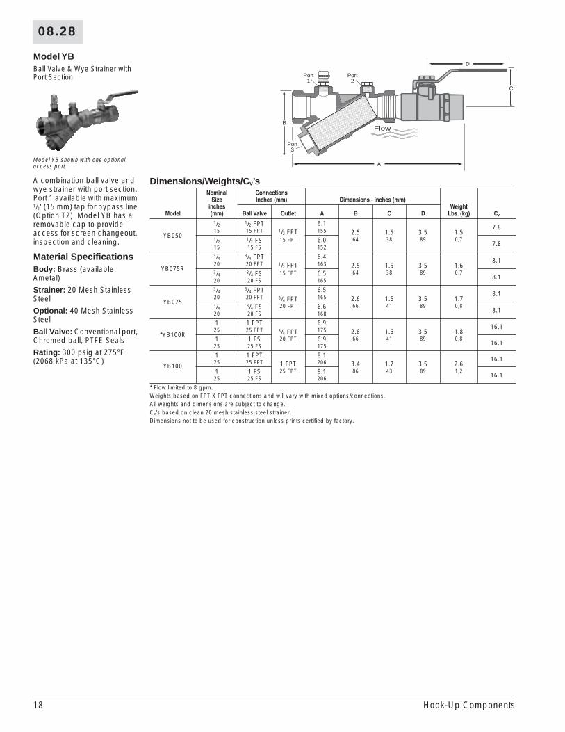
Model YBBall Valve & Wye Strainer with Port Section
Model YB shown with one optional access port
A combination ball valve and wye strainer with port section. Port 1 available with maximum 1/2" (15 mm) tap for bypass line (Option T2). Model YB has a removable cap to provide access for screen changeout, inspection and cleaning.
Material SpecificationsBody: Brass (available Ametal)
Strainer: 20 Mesh Stainless Steel
Optional: 40 Mesh Stainless Steel
Ball Valve: Conventional port, Chromed ball, PTFE Seals
Rating: 300 psig at 275°F (2068 kPa at 135°C)
Dimensions/Weights/Cv’s
Model
NominalSize
inches(mm)
ConnectionsInches (mm) Dimensions - inches (mm)
WeightLbs. (kg) CvBall Valve Outlet A B C D
YB050
1/2 1/2 FPT1/2 FPT15 FPT
6.12.564
1.538
3.589
1.50,7
7.815 15 FPT 1551/2 1/2 FS 6.0 7.815 15 FS 152
YB075R
3/4 3/4 FPT1/2 FPT15 FPT
6.42.564
1.538
3.589
1.60,7
8.120 20 FPT 1633/4 3/4 FS 6.5 8.120 20 FS 165
YB075
3/4 3/4 FPT3/4 FPT20 FPT
6.52.666
1.641
3.589
1.70,8
8.120 20 FPT 1653/4 3/4 FS 6.6 8.120 20 FS 168
*YB100R
1 1 FPT3/4 FPT20 FPT
6.92.666
1.641
3.589
1.80,8
16.125 25 FPT 175
1 1 FS 6.9 16.125 25 FS 175
YB100
1 1 FPT1 FPT25 FPT
8.13.486
1.743
3.589
2.61,2
16.125 25 FPT 206
1 1 FS 8.1 16.125 25 FS 206
* Flow limited to 8 gpm.Weights based on FPT X FPT connections and will vary with mixed options/connections.All weights and dimensions are subject to change.Cv’s based on clean 20 mesh stainless steel strainer.Dimensions not to be used for construction unless prints certified by factory.
A
Port1
Port2
Port3
B
C
D
Flow
Hook-Up Components
08.28
19
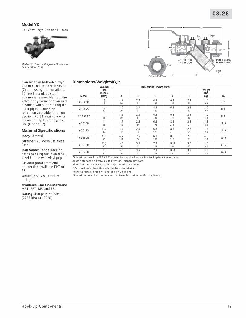
Model YCBall Valve, Wye Strainer & Union
Model YC shown with optional Pressure/Temperature Ports
Combination ball valve, wye strainer and union with seven (7) accessory port locations. 20 mesh stainless steel strainer is removable from the valve body for inspection and cleaning without breaking the main piping. One size reduction available for union section. Port 1 available with maximum 1/2" tap for bypass line (Option T2).
Material SpecificationsBody: Ametal
Strainer: 20 Mesh Stainless Steel
Ball Valve: Teflon packing, brass packing nut, plated ball, steel handle with vinyl grip
Blowout-proof stem end connection available FPT or FS
Union: Brass with EPDM o-ring
Available End Connections: MPT, FPT, MS and FS
Rating: 400 psig at 250°F (2758 kPa at 120°C)
Dimensions/Weights/Cv’s
Model
NominalSize
inches(mm)
Dimensions - inches (mm)Weight
Lbs. (kg) CvA B C D E
YC00501/2 3.9 2.0 4.8 6.2 2.1 2.0 7.615 99 51 122 157 53 0,9
YC00753/4 3.9 2.0 4.8 6.2 2.1 2.0 8.120 99 51 122 157 53 0,9
YC100R* 1 3.9 2.0 4.8 6.2 2.1 7.0 8.125 99 51 122 157 53 3,2
YC0100 1 4.7 2.6 6.8 8.6 2.8 4.5 18.925 119 66 173 218 71 2,0
YC0125 11/4 4.7 2.6 6.8 8.6 2.8 4.5 20.032 119 66 173 218 71 2,0
YC0150R* 11/2 4.7 2.6 6.8 8.6 2.8 4.5 20.040 119 66 173 218 71 2,0
YC0150 11/2 5.5 3.5 7.9 10.0 3.8 9.3 43.540 140 89 201 254 97 4,2
YC0200 2 5.5 3.5 7.9 10.0 3.8 9.3 44.350 140 89 201 254 97 4,2
Dimensions based on FPT X FPT connections and will vary with mixed options/connections.All weights based on valves with Pressure/Temperature ports.All weights and dimensions are subject to minor changes.Cv’s based on a clean 20 mesh stainless steel strainer.*Denotes female thread not available on union end.Dimensions not to be used for construction unless prints certified by factory.
B
E
D
Port1
Port2
Port 5 at 3:00Port 7 at 9:00
Port3
Port 4 at 3:00Port 6 at 9:00
A C
12:00
3:009:00
Tailpiece End View
Flow
Hook-Up Components
20
08.28
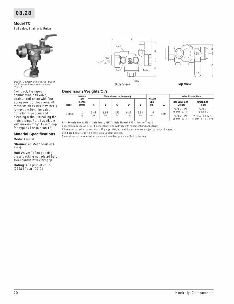
Model TCBall Valve, Strainer & Union
Model TC shown with optional Model HN Hose-end drain valve (shown FS X FS)
Compact, T-shaped combination ball valve, strainer and union with four accessory port locations. 40 mesh stainless steel strainer is removable from the valve body for inspection and cleaning without breaking the main piping. Port 1 available with maximum 1/2" (15 mm) tap for bypass line (Option T2).
Material SpecificationsBody: Ametal
Strainer: 40 Mesh Stainless Steel
Ball Valve: Teflon packing, brass packing nut, plated ball, steel handle with vinyl grip
Rating: 400 psig at 250°F (2758 kPa at 120°C)
Dimensions/Weights/Cv’s
Model
NominalSize
Inches(mm)
Dimensions - inches (mm)Weight
Lbs.(kg) Cv
Valve Connections
A B C D EBall Valve End
(Outlet)Union End
(Inlet)
TC00501/215
3.6593
1.9650
1.7344
0.8722
2.3159
1.60,8
4.08
1/2" FS, FPT 3/8" FS15 mm FS, FPT 10 mm FS
3/4" FS, FPT 1/2" FS, FPT, MPT20 mm FS, FPT 15 mm FS, FPT, MPT
FS = Female Sweat; MS = Male Sweat; MPT = Male Thread; FPT = Female ThreadDimensions based on FT X FT connections and will vary with mixed option/connections.All weights based on valves with NPT plugs. Weights and dimensions are subject to minor changes.Cv’s based on a clean 40 mesh stainless steel strainer.Dimensions not to be used for construction unless prints certified by factory.
Port 1
Port 3
Port 2
Port 4
Flow
Side View Top View
Hook-Up Components

08.28
21
Model UBShut-off Valve with Union Option
Model UB shown with optional Pressure/Temperature Port, Air Vent, Male Thread X Female Sweat Ends.
Model UB is a shut-off valve with blowout proof stem. Micro handle customary on the A body, and standard handle customary on the B and C bodies; all available with optional adjustable memory stop for shut-off and resetting and vinyl coated grip. Available with union connection or fixed threaded or sweat connections.
Material SpecificationsBody: Ametal
Rating: 600 psig at 250°F (4136 kPa at 120°C)
Union (Optional): Brass (available Ametal) with EPDM o-ring
Fixed Connection: Brass (available Ametal)
O-ring: EPDM
Ball Valve: Teflon seats, Teflon packing, plated ball
E
C
B
D A
2
1
3Flow
Configuration Information
Body Size Cv/Kv
Fixed ConnectionsInches (mm)
Union ConnectionsInches (mm)
A1/2 (15) FS, FPT3/4 (20) FS, FPT1 (25) FS, FPT
3/8 (10) FS1/2 (15) FS, FPT, MPT
3/4 (20) FPT, MPT
66,94
B
1/2 (15) FS, FPT3/4 (20) FS, FPT1 (25) FS, FPT
11/4 (32) FS, FPT
1/2 (15) FS, FPT3/4 (20) FS, FPT1 (25) FS, FPT
11/4 (32) FS, FPT
1921,97
C11/4 (32) FS, FPT11/2 (40) FS, FPT2 (50) FS, FPT
11/4 (32) FS, FPT11/2 (40) FS, FPT2 (50) FS, FPT
6676,30
FS = female sweat; FPT = female thread; MPT = male thread
Product Information
Body Size
Conn. Type
Body DimensionsInches (mm)
WgtLbs.(kg.)
Connection DimensionsInches (mm) Weight
Lbs. (kg.)A B C D E3/8 1/2 3/4 1 3/8 1/2 3/4 1 3/8 1/2 3/4 110 15 20 25 10 15 20 25 10 15 20 25
A†
FS – 0.5 0.8 1.2 – 1.1 1.2 1.5 – 0.1 0.1 0.2– 14 20 29 – 28 29 29 – 0,05 0,05 0,08
FPT – 0.7 0.8 1.1 – 1.1 1.3 1.6 – 0.1 0.2 0.4– 17 20 29 – 28 33 29 – 0,06 0,08 0,16
Union FS 3.6 2.3 2.1 0.9 1.4 1.5 1.6 – 1.6 1.6 1.6 – 0.5 0.4 0.4 –91 58 53 0,4 35 37 40 – 39 39 39 – 0,20 0,20 0,20 –
Union FPT
– 1.5 – – – 1.6 – – – 0.5 – –– 37 – – – 39 – – – 0,21 – –
Union MPT
– 2.4 2.2 – – 1.6 1.6 – – 0.5 0.5 –– 61 57 – – 39 39 – – 0,24 0,20 –
1/2 3/4 1 11/4 1/2 3/4 1 11/4 1/2 3/4 1 11/415 20 25 32 15 20 25 32 15 20 25 32
B†
FS 0.5 0.8 1.0 1.2 1.3 1.3 1.5 1.8 0.2 0.2 0.1 0.314 19 25 28 34 34 37 51 0,07 0,08 0,05 0,20
FPT 0.7 0.7 0.9 1.1 1.3 1.3 1.6 2.0 0.2 0.2 0.3 0.418 19 24 32 34 34 41 45 0,08 0,09 0,13 0,12
Union FS 3.8 2.3 2.2 1.2 1.5 1.7 1.7 1.8 2.1 2.1 2.4 2.8 0.4 0.5 2.7 1.297 58 56 0,5 37 43 42 45 53 53 60 72 0,20 0,20 1,21 0,54
Union FPT
1.5 1.6 1.7 1.7 2.1 2.1 2.4 2.8 0.5 0.5 2.8 1.339 40 43 43 53 53 60 72 0,22 0,22 1,25 0,57
Union MPT
2.4 2.2 2.5 2.5 2.1 2.1 2.4 2.8 0.6 0.6 3.0 1.560 56 63 64 53 53 60 72 0,26 0,28 1,34 0,69
Body Size
Conn. Type
Body DimensionsInches (mm)
WgtLbs.(kg.)
Connection DimensionsInches (mm) Weight
Lbs. (kg.)A B C D E
11/4 11/2 2 11/4 11/2 2 11/4 11/2 232 40 50 32 40 50 32 40 50
C†
FS 1.2 1.2 1.7 2.4 2.4 2.7 0.7 0.6 0.729 31 42 62 62 69 0,31 0,28 0,29
FPT 0.9 0.9 1.2 2.4 2.4 2.9 0.8 0.6 0.623 23 29 62 62 72 0,34 0,29 0,29
Union FS 5.4 5.5 3.5 3.6 2.0 2.1 2.4 3.5 3.5 3.8 2.4 2.4 2.8137 140 89 1,6 51 54 61 88 88 97 1,10 1,10 1,27
Union FPT 1.9 1.9 2.0 3.5 3.5 3.8 2.7 2.7 3.149 49 50 88 88 97 1,24 1,24 1,38
Union MPT 3.0 3.0 2.8 3.5 3.5 3.8 2.8 3.0 2.875 76 72 88 88 97 1,28 1,37 1,29
All weights and dimensions are subject to minor changes.* The end to end dimension may be calculated by using the two applicable D dimensions and adding to the A dimension of the valve body. Dimensions not to be used for construction unless prints certified by factory.† Body only weights: A = 0.9/0,4; B - 1.2/0,5; C = 3.6;1,6.
Hook-Up Components
22
08.28
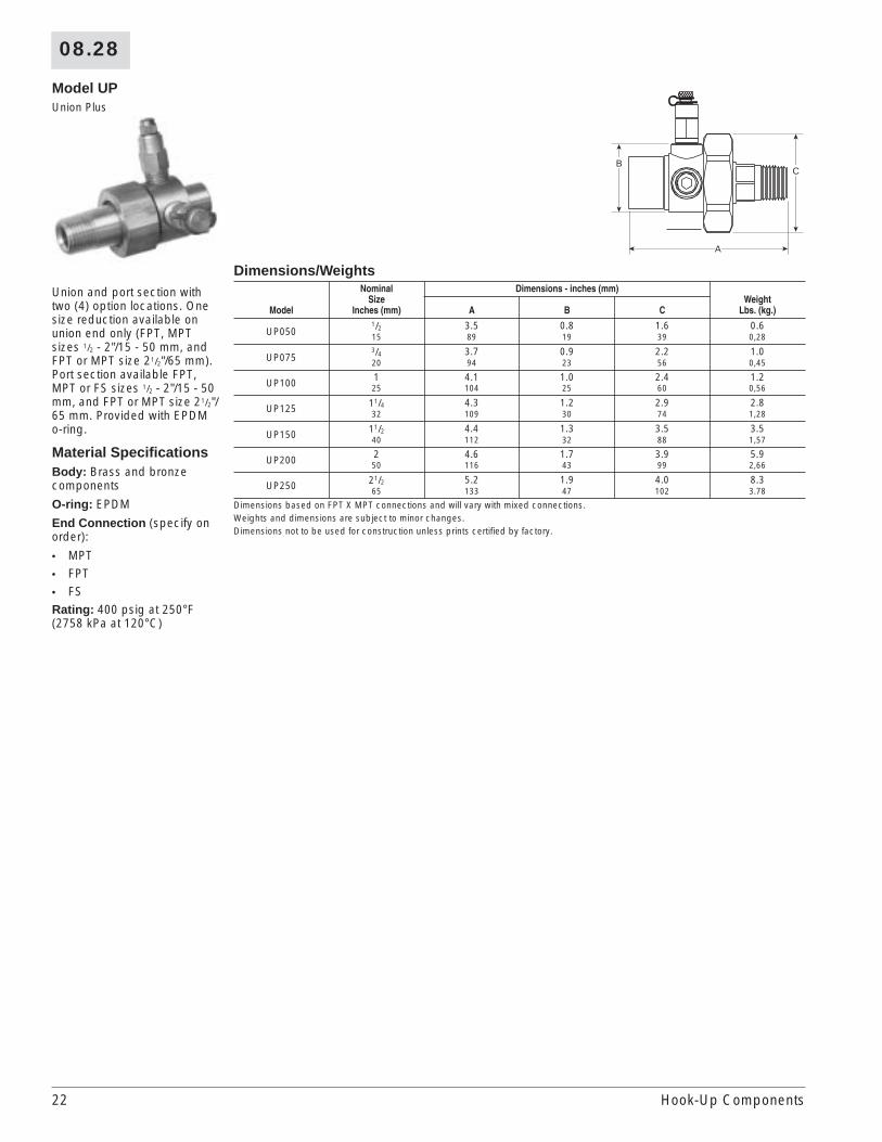
Model UPUnion Plus
Union and port section with two (4) option locations. One size reduction available on union end only (FPT, MPT sizes 1/2 - 2"/15 - 50 mm, and FPT or MPT size 21/2"/65 mm). Port section available FPT, MPT or FS sizes 1/2 - 2"/15 - 50 mm, and FPT or MPT size 21/2"/65 mm. Provided with EPDM o-ring.
Material SpecificationsBody: Brass and bronze components
O-ring: EPDM
End Connection (specify on order):
• MPT• FPT• FSRating: 400 psig at 250°F (2758 kPa at 120°C)
Dimensions/Weights
Model
NominalSize
Inches (mm)
Dimensions - inches (mm)Weight
Lbs. (kg.)A B C
UP0501/2 3.5 0.8 1.6 0.615 89 19 39 0,28
UP0753/4 3.7 0.9 2.2 1.020 94 23 56 0,45
UP100 1 4.1 1.0 2.4 1.225 104 25 60 0,56
UP125 11/4 4.3 1.2 2.9 2.832 109 30 74 1,28
UP150 11/2 4.4 1.3 3.5 3.540 112 32 88 1,57
UP200 2 4.6 1.7 3.9 5.950 116 43 99 2,66
UP250 21/2 5.2 1.9 4.0 8.365 133 47 102 3.78
Dimensions based on FPT X MPT connections and will vary with mixed connections.Weights and dimensions are subject to minor changes.Dimensions not to be used for construction unless prints certified by factory.
C
A
B
Hook-Up Components

08.28
23
Model CW21/2 - 4" (65 - 100 mm) Cast-Iron Y-Strainer, Flanged
Cast-iron flanged strainers feature a machined tapered seat which ensures a perfect fit for the removable, stainless steel screen. 1/4" ports (as shown) are available for additional options. All sizes come complete with flanged blow-off cover, gasket and plug. May be installed in vertical or horizontal pipe lines with blow-off connection at the lower end of the screen. An optional blow-off ball valve will be shipped loose. HB male-ended ball valves can be used for blow-off valves.
Material SpecificationsBody: High tensile ASTM A126 Class B Cast Iron
Screen: Stainless steel
Rating: 125 psig at 350°F (862 kPa at 177°C)
Dimensions/Weights/Cv’s
Model
NominalSize
Inches (mm)
DimensionsInches (mm)
Blow Off NPTWeight
Lbs. (kg.) Cv
ScreensInches (mm)
A B Mesh Opening
CW0250 21/2 10.9 7.6 1.0 42.0 125 0.045 0.04565 277 193 25 19,1 1 1
CW0300 3 11.7 8.3 1.0 49.0 165 0.045 0.04580 297 211 25 22,2 1 1
CW0400 4 13.8 10.1 1.25 86.0 230 0.125 0.125100 351 257 32 39,0 3 3
All weights and dimensions are subject to minor changes.Dimensions not to be used for construction unless prints certified by factory.
Flow
A
Standard³⁄₄" FPT
Additional¹⁄₄" FPTport locations
Blow offFPT connection
B
Hook-Up Components
24
08.28
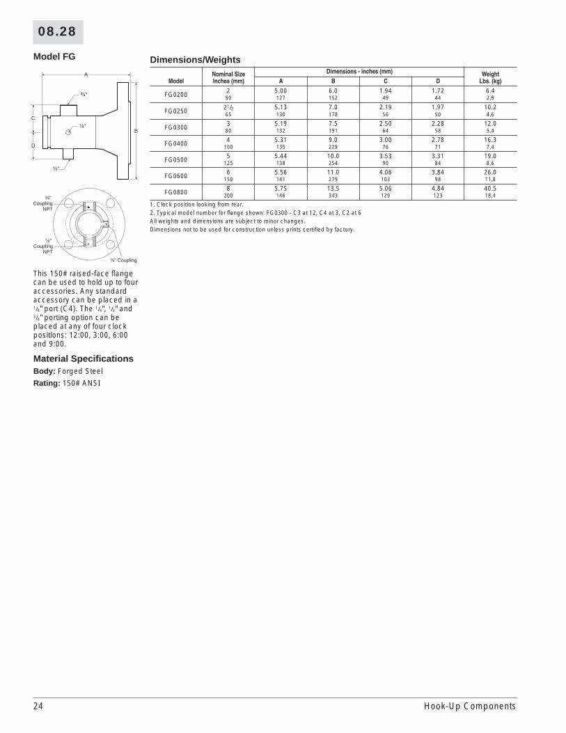
Model FG
This 150# raised-face flange can be used to hold up to four accessories. Any standard accessory can be placed in a 1/4" port (C4). The 1/4", 1/2" and 3/4" porting option can be placed at any of four clock positions: 12:00, 3:00, 6:00 and 9:00.
Material SpecificationsBody: Forged Steel
Rating: 150# ANSI
A
B
³⁄₄"
¹⁄₄"
¹⁄₂"
D
C
³⁄₄" Coupling
NPT
¹⁄₂" Coupling
NPT
¹⁄₄" Coupling
Dimensions/Weights
ModelNominal SizeInches (mm)
Dimensions - inches (mm) WeightLbs. (kg)A B C D
FG0200 2 5.00 6.0 1.94 1.72 6.450 127 152 49 44 2,9
FG0250 21/2 5.13 7.0 2.19 1.97 10.265 130 178 56 50 4,6
FG0300 3 5.19 7.5 2.50 2.28 12.080 132 191 64 58 5,4
FG0400 4 5.31 9.0 3.00 2.78 16.3100 135 229 76 71 7,4
FG0500 5 5.44 10.0 3.53 3.31 19.0125 138 254 90 84 8,6
FG0600 6 5.56 11.0 4.06 3.84 26.0150 141 279 103 98 11,8
FG0800 8 5.75 13.5 5.06 4.84 40.5200 146 343 129 123 18,4
1. Clock position looking from rear.2. Typical model number for flange shown: FG0300 - C3 at 12, C4 at 3, C2 at 6All weights and dimensions are subject to minor changes.Dimensions not to be used for construction unless prints certified by factory.
Hook-Up Components

08.28
25
Model FA2 - 8" (50 - 200 mm) Accessory Flange
This 150# raised-face flange can be used to hold up to four accessories. Any standard accessory can be placed in a 1/4" port (C4). The 1/4", 1/2" and 3/4" porting option can be placed at any of four clock positions: 12:00, 3:00, 6:00 and 9:00.
Material SpecificationsBody: Forged Steel
Rating: 150# ANSI
A
B
³⁄₄"
¹⁄₄"
¹⁄₂"
D
C
³⁄₄" Coupling
NPT
¹⁄₂" Coupling
NPT
¹⁄₄" Coupling
Dimensions/Weights
Model
NominalSize
Inches (mm)
Dimensions - inches (mm)Weight
Lbs. (kg)A B C D
FA0200 2 5.00 6.0 1.94 1.72 6.450 127 152 49 44 2,9
FA0250 21/2 5.13 7.0 2.19 1.97 10.265 130 178 56 50 4,6
FA0300 3 5.19 7.5 2.50 2.28 12.080 132 191 64 58 5,4
FA0400 4 5.31 9.0 3.00 2.78 16.3100 135 229 76 71 7,4
FA0500 5 5.44 10.0 3.53 3.31 19.0125 135 254 90 84 8,6
FA0600 6 5.56 11.0 4.06 3.84 26.0150 141 279 103 98 11,8
FA0600 8 5.75 13.5 5.06 4.84 40.5200 146 343 129 123 18,4
1. Clock position looking from rear.2. Typical model number for flange shown: FA0300 - C3 at 12, C4 at 3, C2 at 6All weights and dimensions are subject to minor changes.Dimensions not to be used for construction unless prints certified by factory.
Hook-Up Components
26
08.28
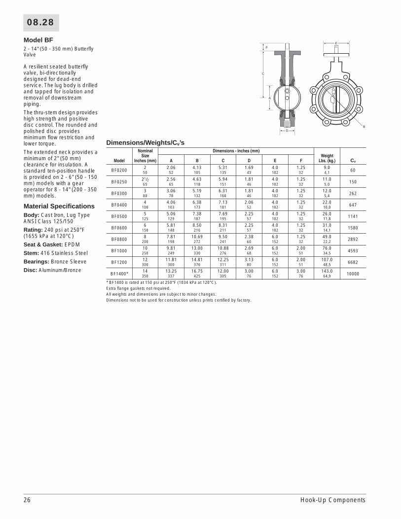
Model BF2 - 14" (50 - 350 mm) Butterfly Valve
A resilient seated butterfly valve, bi-directionally designed for dead-end service. The lug body is drilled and tapped for isolation and removal of downstream piping.
The thru-stem design provides high strength and positive disc control. The rounded and polished disc provides minimum flow restriction and lower torque.
The extended neck provides a minimum of 2" (50 mm) clearance for insulation. A standard ten-position handle is provided on 2 - 6" (50 - 150 mm) models with a gear operator for 8 - 14" (200 - 350 mm) models.
Material SpecificationsBody: Cast Iron, Lug Type ANSI Class 125/150
Rating: 240 psi at 250°F (1655 kPa at 120°C)
Seat & Gasket: EPDM
Stem: 416 Stainless Steel
Bearings: Bronze Sleeve
Disc: Aluminum/Bronze
Dimensions/Weights/Cv’s
Model
NominalSize
Inches (mm)
Dimensions - inches (mm)Weight
Lbs. (kg.) CvA B C D E F
BF0200 2 2.06 4.13 5.31 1.69 4.0 1.25 9.0 6050 52 105 135 43 102 32 4,1
BF0250 21/2 2.56 4.63 5.94 1.81 4.0 1.25 11.0 15065 65 118 151 46 102 32 5,0
BF0300 3 3.06 5.19 6.31 1.81 4.0 1.25 12.0 26280 78 132 160 46 102 32 5,4
BF0400 4 4.06 6.38 7.13 2.06 4.0 1.25 22.0 647100 103 173 181 52 102 32 10,0
BF0500 5 5.06 7.38 7.69 2.25 4.0 1.25 26.0 1141125 129 187 195 57 102 32 11,8
BF0600 6 5.81 8.50 8.31 2.25 4.0 1.25 31.0 1580150 148 216 211 57 102 32 14,1
BF0800 8 7.81 10.69 9.50 2.38 6.0 1.25 49.0 2892200 198 272 241 60 152 32 22,2
BF1000 10 9.81 13.00 10.88 2.69 6.0 2.00 76.0 4593250 249 330 276 68 152 51 34,5
BF1200 12 11.81 14.81 12.25 3.13 6.0 2.00 107.0 6682300 300 376 311 80 152 51 48,5
BF1400* 14 13.25 16.75 12.00 3.00 6.0 3.00 143.0 10000350 337 425 305 76 152 76 64,9
* BF1400 is rated at 150 psi at 250°F (1034 kPa at 120°C).Extra flange gaskets not required.All weights and dimensions are subject to minor changes.Dimensions not to be used for construction unless prints certified by factory.
E
DB
C
A
F
Hook-Up Components
27
08.28
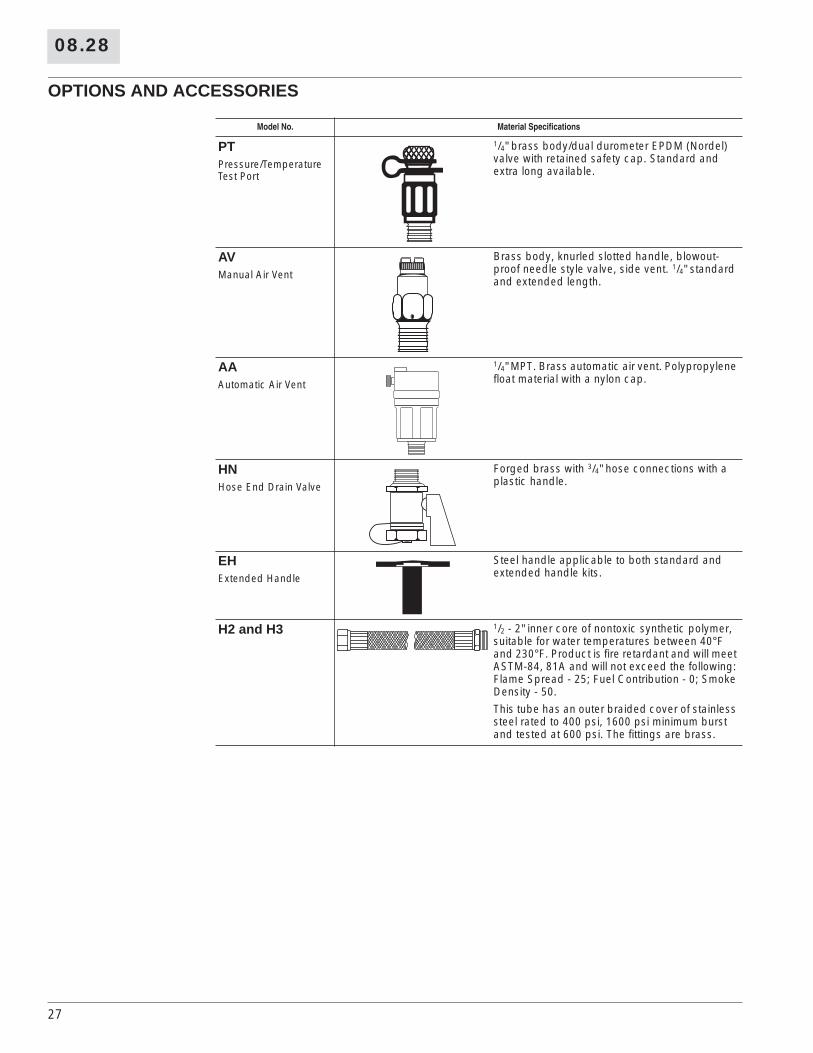
OPTIONS AND ACCESSORIES
Model No. Material Specifications
PTPressure/Temperature Test Port
1/4" brass body/dual durometer EPDM (Nordel) valve with retained safety cap. Standard and extra long available.
AVManual Air Vent
Brass body, knurled slotted handle, blowout-proof needle style valve, side vent. 1/4" standard and extended length.
AAAutomatic Air Vent
1/4" MPT. Brass automatic air vent. Polypropylene float material with a nylon cap.
HNHose End Drain Valve
Forged brass with 3/4" hose connections with a plastic handle.
EHExtended Handle
Steel handle applicable to both standard and extended handle kits.
H2 and H3 1/2 - 2" inner core of nontoxic synthetic polymer, suitable for water temperatures between 40°F and 230°F. Product is fire retardant and will meet ASTM-84, 81A and will not exceed the following: Flame Spread - 25; Fuel Contribution - 0; Smoke Density - 50.
This tube has an outer braided cover of stainless steel rated to 400 psi, 1600 psi minimum burst and tested at 600 psi. The fittings are brass.