automated design exploration and optimization + hpc … · automated design exploration and...
TRANSCRIPT

© 2011 ANSYS, Inc. May 9, 2012 1
Automated Design Exploration and Optimization + HPC Best Practices

© 2011 ANSYS, Inc. May 9, 2012 2
• The Path to Robust Design
• ANSYS DesignXplorer
• Mesh Morphing and Optimizer
• RBF Morph
• Adjoint Solver
• HPC Best Practices
Outline

© 2011 ANSYS, Inc. May 9, 2012 3
The Path to Robust Design
Single Physics Solution
•Accuracy, robustness, speed…
Multiphysics Solution
•Integration Platform
“What if” Study
•Parametric Platform
Design Exploration
•DOE, Response Surfaces, Correlation, Sensitivity, Unified reporting, etc.
Optimization
•Algorithms
•Published API
Robust Design •Six Sigma Analysis
•Probabilistic Algorithms
•Adjoint solver methods
Robust Design is an ANSYS Advantage

© 2011 ANSYS, Inc. May 9, 2012 4
Parametric CAD Connections
Pervasive Parameters
Persistent Updates
Managed State, Update Mechanisms
Remote Solve Manager (RSM)
…
Needed for "What If?"
“What If?”
Parametric Persistence is an ANSYS Advantage!
Interactively adjust the parameter values and “Update”

© 2011 ANSYS, Inc. May 9, 2012 5
Design Exploration
Design Exploration is an ANSYS Advantage

© 2011 ANSYS, Inc. May 9, 2012 6
Optimization
Optimal Candidates

© 2011 ANSYS, Inc. May 9, 2012 7
Exhaust manifold design
Input Parameters Outlet Diameter of the manifold Thickness at inlet External Temperature Engine RPM
All samples reports max deformation below 1.5 mm
Parametric Geometry
Pressure & Flow Velocity
Thermal
Deformation
Stress
Response Parameters Max Flow Temperature Max Deformation Max Von-Mises stress
Uncertainty of input parameters
Maximum Displacement should not exceed 1.5 mm
Response Surface showing the effect of engine speed and thickness at outlet on the maximum deformation
Six Sigma Analysis
Six Sigma Analysis
© 2011 ANSYS, Inc. May 9, 2012 9
ANSYS DesignXplorer

© 2011 ANSYS, Inc. May 9, 2012 10
ANSYS DesignXplorer
DesignXplorer is everything under this Parameter bar…
• Low cost & easy to use!
• It drives Workbench
• Improves the ROI!
DX
ANSYS Workbench
Solvers

© 2011 ANSYS, Inc. May 9, 2012 11
Design of Experiments
With little more effort than for a single run, you can use
DesignXplorer to create a DOE and run many variations.

© 2011 ANSYS, Inc. May 9, 2012 12
Correlation Matrix
Understand how your parameters are correlated/influenced by other parameters!

© 2011 ANSYS, Inc. May 9, 2012 13
Sensitivity
Understand which parameters your
design is most sensitive to!
© 2011 ANSYS, Inc. May 9, 2012 14
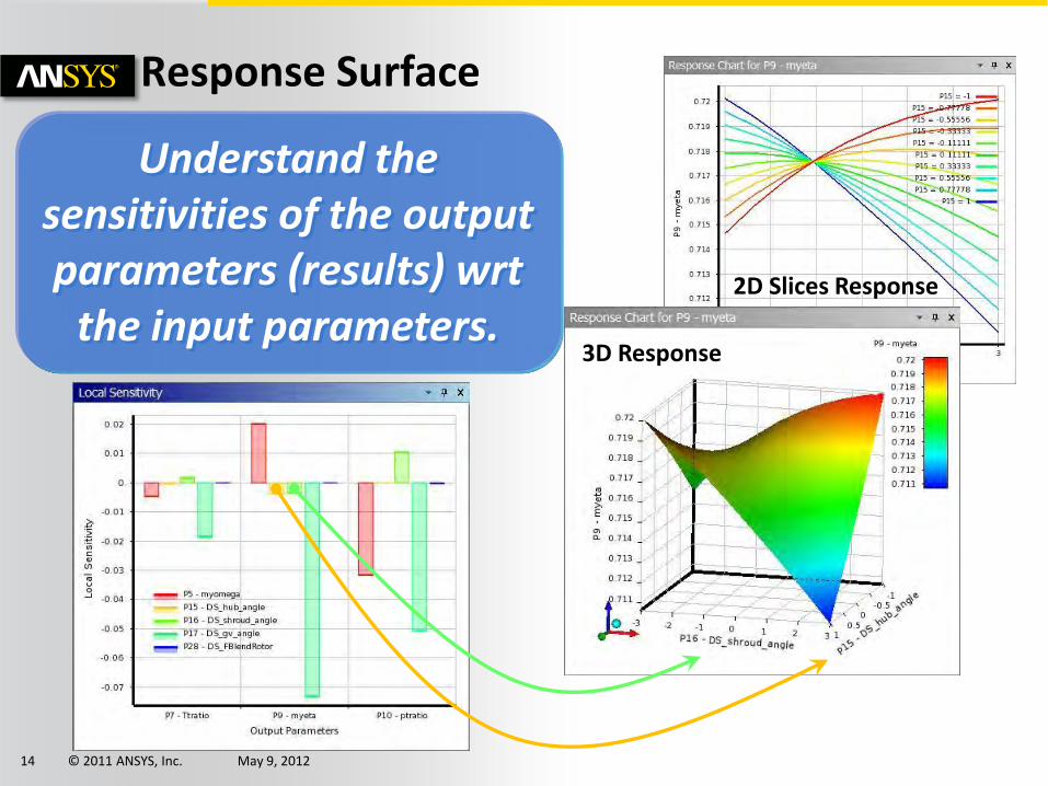
Response Surface
Understand the sensitivities of the output parameters (results) wrt
the input parameters. 3D Response
2D Slices Response
© 2011 ANSYS, Inc. May 9, 2012 15
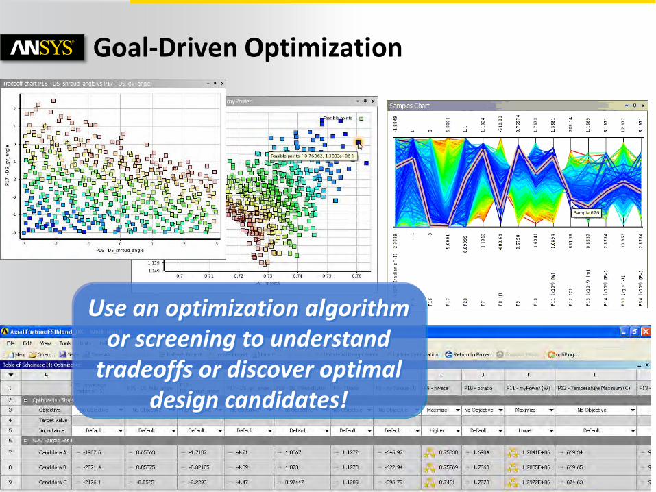
Goal-Driven Optimization
Use an optimization algorithm or screening to understand
tradeoffs or discover optimal design candidates!

© 2011 ANSYS, Inc. May 9, 2012 16
Robustness Evaluation
Input parameters have variation!
Output parameters vary also!
Understand how your performance will vary with your design tolerances?
Make sure your design is robust!
Six Sigma, TQM
Predict how many parts
will likely fail?
Understand which inputs require the
greatest control?

© 2011 ANSYS, Inc. May 9, 2012 17
P3
P2
P1
• Need uniform outflow
• Minimize pressure drop B
AD
GO
OD
Pressu
re Dro
p Fl
ow
Un
ifo
rmit
y
Go
od
Bad
Example 1: Slit Die

© 2011 ANSYS, Inc. May 9, 2012 18
Example 2: Combustor
− 3 parameters
− Minimize pressure loss
− Minimize mach number
Inlet
Outlet
Outlet
Outlet
Dump Gap
Diffuser Length
Exit Height
Sensitivity

© 2011 ANSYS, Inc. May 9, 2012 19
Mesh Morphing and Optimizer

© 2011 ANSYS, Inc. May 9, 2012 20
Fluent Morpher-Optimization Feature
• Allows users to optimize product design based on shape deformation to achieve design objective
• Based on free-form deformation tool coupled with various optimization methods

© 2011 ANSYS, Inc. May 9, 2012 21
Mesh Morphing
Applies a geometric design change directly to the mesh in the solver
Uses a Bernstein polynomial-based morphing scheme
• Freeform mesh deformation defined on a matrix of control points leads to a smooth deformation
• Works on all mesh types (Tet/Prism, CutCell, HexaCore, Polyhedral)
User prescribes the scale and direction of deformations to control points distributed evenly through the rectilinear region.

© 2011 ANSYS, Inc. May 9, 2012 22
Process
OR What if? Optimizer
Setup Case
Run
Setup Morph
Evaluate
Choose “best” design
Regions
Parameters
Deformation
Setup Case
Run
Setup Optimizer
Optimize
Optimal Solution
Morph
Optimizer
Auto

© 2011 ANSYS, Inc. May 9, 2012 23
Deformation Definition
• Define constraint(s) (if any)
• Select control points and prescribe the relative ranges of motion

© 2011 ANSYS, Inc. May 9, 2012 24
Objective Function
Baseline Design Optimized Design
• Objective Function: Equal flow rate

© 2011 ANSYS, Inc. May 9, 2012 25
Optimizer Algorithms; Compass, Powell, Rosenbrock, Simplex, Torczon
Auto
• Optimize!
© 2011 ANSYS, Inc. May 9, 2012 26
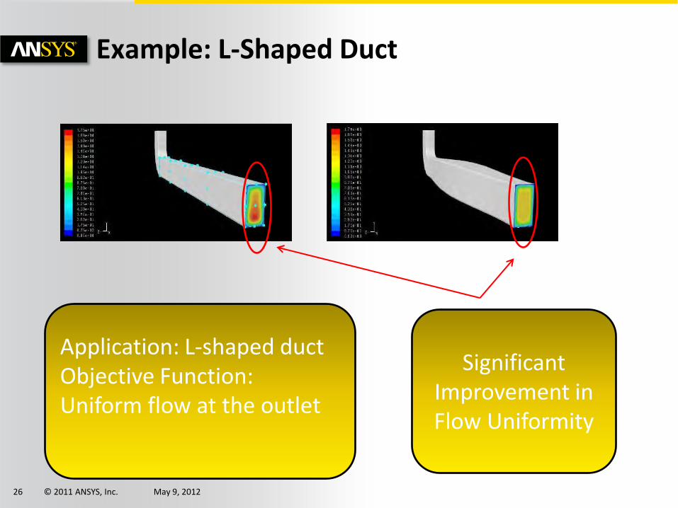
Example: L-Shaped Duct
Application: L-shaped duct Objective Function: Uniform flow at the outlet
Significant Improvement in Flow Uniformity

© 2011 ANSYS, Inc. May 9, 2012 27
RBF Morph

© 2011 ANSYS, Inc. May 9, 2012 28
• The user-friendly RBF Morph add-on module is fully integrated within Fluent (GUI, TUI & solving stage) and Workbench
• Mesh-independent RBF fit used for surface mesh morphing and volume mesh smoothing
• Parallel calculation allows to morph large size models (many millions of cells) in a short time
• Management of every kind of mesh element type (tetrahedral, hexahedral, polyhedral, etc.)
• Ability to convert morphed mesh surfaces back into CAD
• Multi fit makes the Fluent case truly parametric (only 1 mesh is stored)
• Precision: exact nodal movement and exact feature preservation.
RBF Morph Features

© 2011 ANSYS, Inc. May 9, 2012 29
• A system of radial functions is used to fit a solution for the mesh movement/morphing, from a list of source points and their prescribed displacements
• Radial Basis Function interpolation is used to derive the displacement at any location in the space • The RBF problem definition is mesh independent.
How Does RBF-Morph work?

© 2011 ANSYS, Inc. May 9, 2012 30
RBF-Morph is Integrated with Fluent

© 2011 ANSYS, Inc. May 9, 2012 31
Example 1: Internal Flow
Here, a pipe is projected onto a previously defined STL shape

© 2011 ANSYS, Inc. May 9, 2012 32
Example 2: External Flow
courtesy of Ignazio Maria
Viola
Ship sail rotation

© 2011 ANSYS, Inc. May 9, 2012 33
Example 3: External Flow

© 2011 ANSYS, Inc. May 9, 2012 34
• Recently conducted conceptual study by ANSYS in conjunction with Volvo Cars
• 50 Million cell hybrid mesh of Volvo XC60
• 50 Design variants investigated using RBF-Morph Addon for ANSYS Fluent and Workbench Design Explorer
• 50 hours total clock time to complete full optimisation on HPC Cluster
• ~4% Reduction in total drag force
Courtesy of Volvo Cars
Example 4: 50:50:50 Optimisation

© 2011 ANSYS, Inc. May 9, 2012 35
Example 5: Ship Hull Optimisation
• Ship hull hydrodynamics optimisation study
• Block hexahedral mesh from ICEM CFD
• 50 Design variants investigated using RBF-Morph Addon for ANSYS Fluent and Workbench Design Explorer
• 7.9% Reduction in total drag force
Courtesy of Leeds University

© 2011 ANSYS, Inc. May 9, 2012 36
Adjoint Solver

© 2011 ANSYS, Inc. May 9, 2012 37
An adjoint solver allows specific information about a fluid system to be computed that is very difficult to gather otherwise.
The adjoint solution itself is a set of derivatives.
• They are not particularly useful in their raw form and must be post-processed appropriately.
• The derivative of an engineering quantity with respect to all of the inputs for the system can be computed in a single calculation.
– Example: Sensitivity of the drag on an airfoil to its shape.
There are 4 main ways in which these derivatives can be used:
1. Qualitative guidance on what can influence the performance of a system strongly.
2. Quantitative guidance on the anticipated effect of specific design changes.
3. Guidance on important factors in solver numerics.
4. Gradient-based design optimization.
Adjoint Solution?

© 2011 ANSYS, Inc. May 9, 2012 38
GOAL: Identify features of a system design that are most influential in the performance of the system.
EXAMPLE: – Sensitivity of the Drag on a NACA 0012 airfoil to changes in the
shape of the airfoil.
– The shape sensitivity field is extracted from the adjoint solution in a post-processing step.
How to Use the Results - Qualitative
High sensitivity – changes to shape have a big effect on drag
Low sensitivity – changes to shape have a small effect on drag
© 2011 ANSYS, Inc. May 9, 2012 39
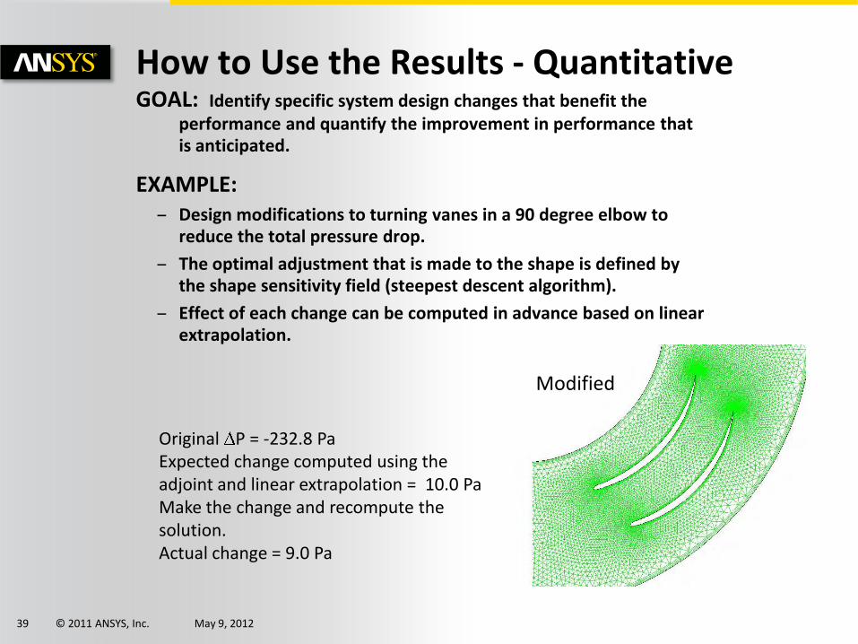
GOAL: Identify specific system design changes that benefit the performance and quantify the improvement in performance that is anticipated.
EXAMPLE: – Design modifications to turning vanes in a 90 degree elbow to
reduce the total pressure drop.
– The optimal adjustment that is made to the shape is defined by the shape sensitivity field (steepest descent algorithm).
– Effect of each change can be computed in advance based on linear extrapolation.
How to Use the Results - Quantitative
Original P = -232.8 Pa Expected change computed using the adjoint and linear extrapolation = 10.0 Pa Make the change and recompute the solution. Actual change = 9.0 Pa
Baseline Modified

© 2011 ANSYS, Inc. May 9, 2012 40
GOAL: Identify aspects of the solver numerics and computational mesh that have a strong influence on quantities that are being computed that are of engineering interest.
EXAMPLE: – Use the adjoint solution to identify parts of the mesh where mesh
adaption will benefit the computed drag by reducing the influence of discretization errors.
How to Use the Results - Solver Numerics
Baseline Mesh Adapted Mesh
Adapted Mesh Detail

© 2011 ANSYS, Inc. May 9, 2012 41
GOAL: Perform a sequence of automated design modifications to improve a specific performance measure for a system
EXAMPLE: – Gradient-based optimization of the total pressure drop in a pipe.
– Flow solution is recomputed and the adjoint recomputed at each design iteration.
How to Use the Results - Optimization
0
10
20
30
40
50
60
70
80
90
100
0 10 20 30 p
tot [P
a]
Iteration
Initial design
Final design
30% reduction in total pressure drop after 30 design iterations

© 2011 ANSYS, Inc. May 9, 2012 42
Once a desired change to the geometry of the system has been selected, how is that change to be made?
• Mesh morphing provides a convenient and powerful means of changing the geometry and the computational mesh.
– Use Bernstein polynomial-based morphing scheme discussed earlier
Mesh Morphing

© 2011 ANSYS, Inc. May 9, 2012 43
• Example: Sensitivity of lift to surface shape
• Select portions of the geometry to be modified
• Adjoint to deformation operation
• Surface shape sensitivity becomes control point sensitivity (chain rule for differentiation)
• Benefit of this approach is two-fold
• Smooths the surface sensitivity field
• Provides a smooth interior and boundary mesh deformation
Mesh Morphing & Adjoint Data
Flow

© 2011 ANSYS, Inc. May 9, 2012 44
The adjoint solution is determined based on the specific flow physics of the problem in hand.
The effect of other practical engineering constraints must be reconciled with the adjoint data to decide on an allowable design change.
Example:
– Some walls within the control volume may be constrained not to move.
– A minimal adjustment is made to the control-point sensitivity field so that deformation of the fixed walls is eliminated.
Mesh Morphing, Adjoint Data & Constraints
Fixed wall
Fixed wall
Moveable walls

© 2011 ANSYS, Inc. May 9, 2012 45
The adjoint solver is released with all Fluent 14 packages.
Documentation is available
• Theory
• Usage
• Tutorial
• Case study
Training is available
Functionality is activated by Loading the adjoint solver add-on module
A new menu item is added at the top level
Current Functionality

© 2011 ANSYS, Inc. May 9, 2012 46
Key initial application areas are:
• Low-speed external aerodynamics
– F1 (increase downforce)
– Production automobiles (decrease drag)
• Low-speed internal flows
– Total pressure drop (reduce losses)
Current Functionality Application Drivers
• Ratios • Products • Variances • Linear combinations • Unary operations
In Fluent 14.5 a mechanism for users to define a wide range of observables of interest will be provided.
• Forces • Moments • Pressure drop • Swirl

© 2011 ANSYS, Inc. May 9, 2012 47
Current Scope
ANSYS-Fluent flow solver has very broad scope
Adjoint is configured to compute solutions based on some assumptions
• Steady, incompressible, laminar flow.
• Steady, incompressible, turbulent flow with standard wall functions.
• First-order discretization in space.
• Frozen turbulence.
The primary flow solution does NOT need to be run with these restrictions
• Strong evidence that these assumptions do not undermine the utility of the adjoint solution data for engineering purposes.
Fully parallelized.
Gradient algorithm for shape modification
• Mesh morphing using control points.
Adjoint-based solution adaption

© 2011 ANSYS, Inc. May 9, 2012 48
Example 1: Automotive Aerodynamics
Surface map of the drag sensitivity to shape changes
Surface map of the drag sensitivity to shape changes Surface map of the drag sensitivity to shape changes

© 2011 ANSYS, Inc. May 9, 2012 49
Aggressive adjustment results in a 17% reduction in loss in just one design iteration
Example 2: Pressure Drop in a Duct Total Pressure Drop (Pa)
Geometry Predicted Result
Original --- -22.0
Modified -14.8 -18.3

© 2011 ANSYS, Inc. May 9, 2012 50
HPC Best Practices

© 2011 ANSYS, Inc. May 9, 2012 51
• Know your hardware lifecycle
• Have a goal in mind for what you want to achieve
• Using Licensing productively
• Using ANSYS provided processes effectively
Guidelines :

© 2011 ANSYS, Inc. May 9, 2012 52
• This section is meant to provide an overview of the different hardware components and how they can effect solution time.
• Hopefully this will give you some of the tools to understand why some of the benchmark numbers in better detail.
• ANSYS would always recommend that the best thing to do before buying a system is to look at the latest benchmarks.
• If you are not sure please ask.
Hardware Considerations

© 2011 ANSYS, Inc. May 9, 2012 53
Effect of Clock Speed
Impact of CPU Clock on Application PerformanceProcessor: Xeon X5600 Series
Hyper Threading: OFF, TURBO: ONActive cores: 12/node; Memory speed: 1333 MHz
(performance measure is improvement relative to CPU Clock 2.66 GHz)
0.80
0.85
0.90
0.95
1.00
1.05
1.10
1.15
1.20
1.25
1.30
1.35
1.40
Clock Ratio eddy_417K aircraft_2M turbo_500K sedan_4M truck_14M
ANSYS/FLUENT Model
Imp
rov
em
en
t d
ue
to
Clo
ck
2.66 GHz2.93 GHz3.47 GHz
Hig
he
r is
be
tte
r

© 2011 ANSYS, Inc. May 9, 2012 54
Effect of Memory Speed
• We can see here the effect of memory speed.
• This has implications on how you build your hardware.
• Some processors types have slower memory speeds by default.
• On other processors non-optimally filling the memory channels can slow the memory speed.
Impact of DIMM speed on ANSYS/FLUENT Application Performance (Intel Xeon x5670, 2.93 GHz)
Hyper Threading: OFF, TURBO: ONActive threads per node: 12
(performance measure improvement is relative to memory speed of 1066 MHz)
80%
85%
90%
95%
100%
105%
110%
115%
120%
125%
130%
eddy_417K turbo_500K aircraft_2M sedan_4M truck_14M
ANSYS/FLUENT Model
Imp
ac
t o
f M
em
ory
Sp
ee
d
1066 MHz1333 MHz

© 2011 ANSYS, Inc. May 9, 2012 55
Turbo Boost (Intel) / Turbo Core (AMD)
• Turbo Boost (Intel)/ Turbo Core(AMD) is a form of over-clocking that allows you to give more GHz to individual processors when others are idle.
• With the Intel’s have seen variable performance with this ranging between 0-8% improvement depending on the numbers of cores in use.
• The graph below for CFX on a Intel X5550. This only sees a maximum of 2.5% improvement.

© 2011 ANSYS, Inc. May 9, 2012 56
Hyper-Threading: ANSYS Fluent
• Hyper-Threading Technology makes a single physical processor appear as two logical processors.
• This is not the same as physically having two logical processors and does not give double the speedup.
• In our tests we’ve seen as high as a 20% increase in performance although you can see the actual performance can be quite variable from the graph opposite.
• It is worth noting that this has licensing implications as you would need to oversubscribe the physical cores and hence would need double the HPC Licenses.
Evaluation of Hyperthreading on ANSYS/FLUENT Performance iDataplex M3 (Intel Xeon x5670, 2.93 GHz)
TURBO: ON(measurement is improvement relative ot Hyperthtreading OFF)
0.90
0.95
1.00
1.05
1.10
eddy_417K turbo_500K aircraft_2M sedan_4M truck_14M
ANSYS/FLUENT Model
Imp
rov
em
et
du
e t
o H
yp
ert
hre
ad
ing
.
HT OFF (12 threads on 12 physical cores) HT ON (24 threads on 12 physical cores)
Hig
he
r is
be
tte
r

© 2011 ANSYS, Inc. May 9, 2012 57
• Traditionally Intel take the “power approach” in general in their 2 socket systems (faster core but less of them per processor/socket).
• Traditionally AMD take the economies of scale approach (more cores per processor but individually slower clock speeds).
• Remember that this landscape changes because they are constantly in competition with each other.
• Please note that whilst we do have some numbers for the new Intel Sandy-bridge chips we do not have scaling numbers for the equivalent AMD 6200 series at the time of writing this presentation.
AMD vs. Intel

© 2011 ANSYS, Inc. May 9, 2012 58
2 Socket vs. 4 Socket Systems
• Current 4 socket systems come up slower than their 2 socket counterparts (based on Intel Westmere vs. Xeon E7-8837).
• Clock speed slower
• Memory speed slower
• No additional memory bandwidth.
Performance of ANSYS Fluent on two-socket and four-socket based systems Performance measure is Fluent Rating (higher values are better)
2-socket based Systems IBM HS22/HS22V Blade, 3550/3650 M3, Dx360 M3
(Xeon 5600 Series)
4-socket based Systems IBM HX5 Blade, X3850 (Xeon E7-8837 series)
Nodes Sockets Cores Fluent Rating
Nodes Sockets Cores Fluent Rating
1 2 12 88 1 2 16 96 2 4 24 173 1 4 32 188

© 2011 ANSYS, Inc. May 9, 2012 59
Effect of the Interconnect
ANSYS/FLUENT Performance iDataplex M3 (Intel Xeon x5670, 12C 2.93 GHz)
Network: Gigabit, 10-Gigabit, 4X QDR Infiniband (QLogic, Voltaire)Hyperthreading: OFF, TURBO: ON
Models: truck_14M
0
1000
2000
3000
4000
5000
12 24 48 96 192 384 768
Number of Cores used by a single job
FL
UE
NT
Ra
tin
g
QLogic Voltaire 10-Gigabit Gigabit
Hig
he
r is
be
tte
r
• When going for multiple systems linked together the interconnect becomes an important factor.
• The interconnect is the fabric that connects the nodes.
• We can see from the graph opposite with FLUENT how quickly the performance of Gigabit Ethernet drops off.

© 2011 ANSYS, Inc. May 9, 2012 60
ANSYS Fluent Auto-Partitioning
Auto partitioning is now very quick
Less than 10s to process 800M cells!
Serial pre-partitioning step no
longer required
200M 400M 600M 800M
Time 2.914 4.706 6.617 9.86
0
2
4
6
8
10
12
Tim
e in
se
con
ds
cavity case, 768 cores
192 384 768 1536
Time 5.307 4.542 6.177 8.109
0
1
2
3
4
5
6
7
8
9 Ti
me
in s
eco
nd
s
truck_111m
Time to Partition 200M Cavity Case over 768 cores
Time to Partition 111M Truck Case

© 2011 ANSYS, Inc. May 9, 2012 61
ANSYS CFX Partitioning
Optimize parallel partitioning in multi-core clusters (CFX)β
• Partitioner determines number of connections between partitions and optimizes part.-host assignments
Re-use previous results to initialize calculations on large problem (CFX) β
• Large case interpolation for cases with >~100M nodes
Clean up of coupled partitioning option for multi-domain cases (CFX)
• Eliminates ‘isolated’ partition spots
Dramatically reduced partitioning times for cases with fluid-solid interfaces and very large numbers of regions
Compute Node 1 Compute Node 2
P1
P5
P3
P6
P2 P7
P4 P8
P1
P5 P3
P6
P2 P7
P4
P8
Partitioning step finds adjacency amongst partitions; partitions with max adjacency are grouped on same compute nodes

© 2011 ANSYS, Inc. May 9, 2012 62
ANSYS Fluent Parallel Scalability
0
1000
2000
3000
4000
5000
6000
7000
0 100 200 300 400 500 600
6.3.0
12.0.0
0
5000
10000
15000
20000
25000
0 100 200 300 400 500 600
12.0.0
13.0.0
0
10000
20000
30000
40000
50000
60000
70000
0 500 1000 1500 2000
13.0.0
14.0.0
Xeon X5560 @ 2.80GHz (Nehalem EP)
Intel Harpertown
Intel Westmere
Consistently improved scalability
across releases
Sedan, 4M cells

© 2011 ANSYS, Inc. May 9, 2012 63
ANSYS Fluent Parallel Scalability
SGI ICE 8400EX, Intel 6-core
Intel Harpertown
Intel Westmere hex-core 2.93 GHz
Consistently improved scalability
across releases
Truck, 111M cells
0
50
100
150
200
250
300
350
400
450
0 200 400 600 800 1000 1200
6.3.0
12.0.0
0
200
400
600
800
1000
1200
1400
0 500 1000 1500 2000
12.0.0
13.0.0
0
500
1000
1500
2000
2500
0 1000 2000 3000 4000 5000
13.0.0
14.0.0
© 2011 ANSYS, Inc. May 9, 2012 64
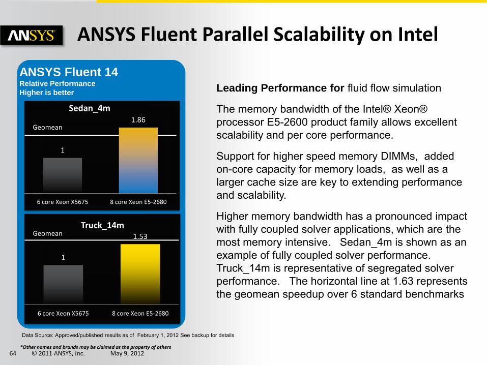
Leading Performance for fluid flow simulation
The memory bandwidth of the Intel® Xeon® processor E5-2600 product family allows excellent scalability and per core performance.
Support for higher speed memory DIMMs, added on-core capacity for memory loads, as well as a larger cache size are key to extending performance and scalability.
Higher memory bandwidth has a pronounced impact with fully coupled solver applications, which are the most memory intensive. Sedan_4m is shown as an example of fully coupled solver performance. Truck_14m is representative of segregated solver performance. The horizontal line at 1.63 represents the geomean speedup over 6 standard benchmarks.
Data Source: Approved/published results as of February 1, 2012 See backup for details
ANSYS Fluent 14 Relative Performance
Higher is better
1
1.86
6 core Xeon X5675 8 core Xeon E5-2680
Sedan_4m
Geomean
1
1.53
6 core Xeon X5675 8 core Xeon E5-2680
Truck_14m Geomean
*Other names and brands may be claimed as the property of others
ANSYS Fluent Parallel Scalability on Intel

© 2011 ANSYS, Inc. May 9, 2012 65
• Good scalability and more operations per
clock make obtaining results on Intel®
Xeon® E5 1.68x faster than on Intel Xeon
5600 platforms
• For end user it is about faster turnaround
or solving larger tasks with the same
resources along with lower TCO
0
20
40
60
80
100
120
140
Air
lift
Reacto
r
Big
Pip
e
Com
bBVM
Com
bED
M
Cylinder
IndyCar
Inte
rnal
LeM
ansCar
LES_001
Pum
p
RadCity
RadFurn
ace
Sta
geCom
pre
ssor
Sta
ticM
ixer1
00M
M
Sta
ticM
ixer1
00
Sta
ticM
ixer2
00
Sta
ticM
ixer
400k
Turb
ine
Wig
ley100
Intel Xeon 5650
Intel Xeon E5-2680
ANSYS CFX Parallel Scalability on Intel
Source: Published/submitted/approved results as of March 6, 2012. Software and workloads used in performance tests
may have been optimized for performance only on Intel microprocessors. Performance tests, such as SYSmark and MobileMark, are
measured using specific computer systems, components, software, operations and functions. Any change to any of those factors may
cause the results to vary. You should consult other information and performance tests to assist you in fully evaluating your contemplated
purchases, including the performance of that product when combined with other products.
Configuration Details: Please reference speaker note. For more information go to http://www.intel.com/performance
*Other names and brands may be claimed as the property of others

© 2011 ANSYS, Inc. May 9, 2012 66
Including Monitors
Scalability with Monitors
• Scalability to higher core counts
• Simulations with monitors including plotting and printing
Hex-core mesh, F1 car, 130 million cells monitor-enabled
0
5
10
15
20
25
30
35
0 200 400 600 800 1000
Example data for scaling with R14 monitors
3072 cores
Monitor support optimizations
maintain scalability expectations

© 2011 ANSYS, Inc. May 9, 2012 67
Fluids I/O
FLUENT, CFX and AUTODYN use a “singular” file structure.
• This means there is one global set of files and every process writes to them.
This methodology falls down at a large number of cores where the file I/O becomes a bottleneck.
• CFX deals with this by using inline compression (cdat)
• FLUENT has both inline compression (cdat) and at v12.x introduced support for a Parallel File (pdat).
Parallel file system support in ANSYS FLUENT
– ~10x - 20x speedup for data write
– Eliminates scaling bottleneck for data intensive simulations on large clusters (e.g., transient flows)
Serial I/O Parallel I/O
ANSYS FLUENT

© 2011 ANSYS, Inc. May 9, 2012 68
• To Demonstrate 50:50:50 Method – Volvo XC60 vehicle model
– Four shape parameters
– RBF Morph (Integrated within FLUENT) to define shape parameters
– Grid morphing in parallel
• ANSYS WorkBench (Frame Work to Automate Process) – To drive shape parameters
– To create DOE
– To perform Goal Driven Optimization
HPC Fluids Demonstration Case
The 50:50:50 Method
50 50 design points in the design
space EXTENT
50 50 million cells used in CFD simulation of each design
point ACCURACY
50 50 hours total elapsed time to simulate all the design points
SPEED
“One – Click” – Entire design space is simulated and post-processed completely automatically after the initial baseline
case setup

© 2011 ANSYS, Inc. May 9, 2012 69
HPC Fluids Demonstration Case Prepare Meshed Model for
Baseline Vehicle Shape
CFD Solver Setup, Define Shape Parameters
Generate DOE using Input Shape Parameters
Collate Data, Perform Optimization
Morph Vehicle Shape
Run CFD Simulation
STEP 1
STEP 2
STEP 3
STEP 4
STEP 5
Mesh Morpher Integrated within FLUENT Solver (FLUENT), Optimizer (DX) & Post Processor (CFD Post) Integrated within
ANSYS WorkBench

© 2011 ANSYS, Inc. May 9, 2012 70
HPC Fluids Demonstration Case
768 Cores 384 Cores 288 Cores 240 Cores 144 Cores
Task Time (Seconds) Time (Seconds) Time
(Seconds) Time
(Seconds) Time
(Seconds)
Baseline Case (i.e. Design Point 1)
Read volume mesh of baseline case into the CFD solver and apply solver settings
225 340 365 481 228
CFD Solution 6979 11153 14409 17256 27246
Writing CFD data file 681 538 558 600 532
Each Subsequent Design Point
Morph vehicle shape 84 59 65 69 100
CFD Solution 1284 1754 2208 2630 4100
Writing CFD data file 734 559 572 621 532
Total Run Time (Wall Clock) Needed for All 50 Design Points (Hours)
30.80 35.63 42.98 50.28 72.19

© 2011 ANSYS, Inc. May 9, 2012 71
HPC Fluids Demonstration Case
Compute Cluster Details
1. Intel’s Endeavor Cluster
2. Intel Xeon X5670 (dual socket)
3. Clock speed 2.93 GHz
4. Six cores per socket (12 cores per node)
5. 24 GB RAM @ 1333 MHz, SMT ON, Turbo ON
6. QDR Infiniband
7. RHEL Server Release 6.1
© 2011 ANSYS, Inc. May 9, 2012 72
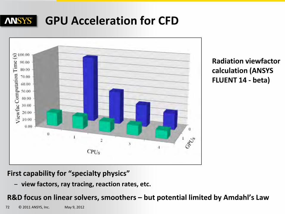
First capability for “specialty physics”
– view factors, ray tracing, reaction rates, etc.
R&D focus on linear solvers, smoothers – but potential limited by Amdahl’s Law
GPU Acceleration for CFD
Radiation viewfactor calculation (ANSYS FLUENT 14 - beta)

© 2011 ANSYS, Inc. May 9, 2012 73
Getting the right setup is balancing act..

© 2011 ANSYS, Inc. May 9, 2012 74
• HPC Licensing Cost
• Cost of Hardware
• Complexity of Deployment and Maintenance
Factors to Consider

© 2011 ANSYS, Inc. May 9, 2012 75
• ANSYS HPC is licensed in either the HPC Workgroup/Enterprise (or individually) or HPC Packs.
• Given that it is licensed per partition (which in most cases translated to a core) – the best value for money is in getting the best scalability per core as possible.
• When running multiple cores make sure you are using them as effectively as the memory bandwidth allows.
HPC Licensing Cost

© 2011 ANSYS, Inc. May 9, 2012 76
• ANSYS will, in general, recommend the best hardware for performance that gets you the best out of your licensing investment. However you may need to make trade-off's for your budget.
• 2 socket systems provide the best performance but more inherently more complexity (and hence cost) because of the need for high speed interconnects when in a cluster.
• Current 4 socket systems have less performance than their 2 socket counterparts but are also cheaper because of their lack of requirement for the high speed interconnects to get to higher numbers of nodes at the low end.
Cost of Hardware
© 2011 ANSYS, Inc. May 9, 2012 77
• A large cluster can have significant overheads in ease of deployment & on-going maintenance costs.
• A 4 socket system, whilst having less performance, may provide an easier deployment and maintenance route at the lower end and will be a better fit to what the average IT department is used to.
• Often users get too caught up on per core performance at the detriment of not getting any extra speedup at all.
• It is important to purchase something you feel you can internally support.
• Purchase 3rd party support for high performance clusters if you do not feel you have the skills to support it internally.
Complexity of Deployment and Maintenance
© 2011 ANSYS, Inc. May 9, 2012 78
If you opt for unsupported infrastructure
– This does not mean that it will not work but you use them at your own risk.
– We may ask you to replicate it on a system that is supported before providing further support if you run into problems!
We recommend:
– Buying Supported Operating systems and Hardware
– Using ANSYS Supported Practices
– Talking to us before buying! It is in all our interests that you get this right!
Remember the Following ...

© 2011 ANSYS, Inc. May 9, 2012 79
ANSYS Partner Solutions – http://www.ansys.com/corporate/partners/partners-hpc.asp
• Reference configurations
• Performance data
• White papers
• Sales contact points
Performance Data – http://www.ansys.com/benchmarks
Information Available
© 2011 ANSYS, Inc. May 9, 2012 80
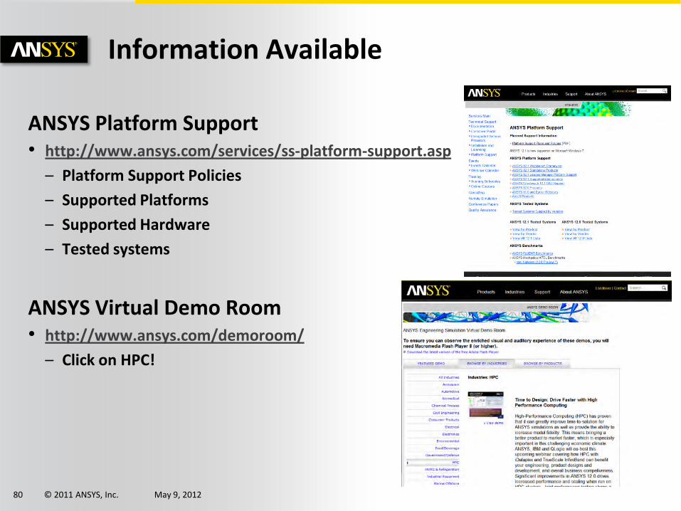
Information Available
ANSYS Platform Support • http://www.ansys.com/services/ss-platform-support.asp
– Platform Support Policies
– Supported Platforms
– Supported Hardware
– Tested systems
ANSYS Virtual Demo Room • http://www.ansys.com/demoroom/
– Click on HPC!

© 2011 ANSYS, Inc. May 9, 2012 81
Information Available
The Manual • Sections on best practices and parallel
processing for various solvers
• Installation walkthroughs for installing the products, parallel processing, licensing and RSM (remote solve manager)
ANSYS Advantage • Online Magazine

© 2011 ANSYS, Inc. May 9, 2012 82
Information Available
Customer Portal • http://www1.ansys.com/customer/
– Knowledge Resources
– Installation and Systems FAQ’s
Customer Support • http://www1.ansys.com/customer/
• Portal, Email or Phone
Global ANSYS network providing Comprehensive Support