automated fiber placement composites for improved ...arrow.utias.utoronto.ca/ncss13/ncsa...
TRANSCRIPT
PASINI LAB
Automated Fiber Placement Composites for
Improved Structural Efficiency of Aircrafts
Kazem Fayazbakhsh & Damiano Pasini
Pasini Lab
Mechanical Engineering
McGill University
May 16th, 2013
UTIAS National Colloquium on Sustainable Aviation
1

PASINI LAB
Outline
• Introduction
• A sustainable aircraft : Boeing 787
• Composite design concepts
• Automated Fiber Placement
• Talk objectives
• Research expertise of the Lab
• Concluding remarks
2
PASINI LAB
A sustainable aircraft : Boeing 787
• Fuel use reduced
• Automated manufacturing technologies
• Emissions cut
• Quieter take-offs and landings
• Point-to-point travel enabled
• End-of-life recycling
• A life cycle approach
3

PASINI LAB
Boeing 787 (a sustainable aircraft)
• Fuel use reduced
• Automated manufacturing technologies
• Emissions cut
• Quieter take-offs and landings
• Point-to-point travel enabled
• End-of-life recycling
• A life cycle approach
4
PASINI LAB
Boeing 787 (a sustainable aircraft)
• Fuel use reduced • Increased use of light weight composite materials
• New engines
• More-efficient system applications
• Modern aerodynamics
• Advanced manufacturing technologies • Automated Fiber Placement
5
PASINI LAB
Boeing 787 (a sustainable aircraft)
• Fuel use reduced • Increased use of light weight composite materials
• New engines
• More-efficient system applications
• Modern aerodynamics
• Advanced manufacturing technologies • Automated Fiber Placement
6

PASINI LAB
Composite design concepts
• Constant stiffness (CS)
• Traditional composite design
• Keeping the fiber angle constant within each layer
• Variable stiffness (VS)
• Allowing fibers to follow curvilinear paths
• More favorable stress distribution
7
Constant stiffness variable stiffness
PASINI LAB
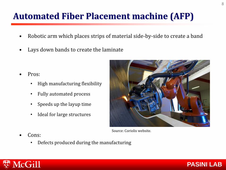
Automated Fiber Placement machine (AFP)
8
• Robotic arm which places strips of material side-by-side to create a band
• Lays down bands to create the laminate
• Pros:
• High manufacturing flexibility
• Fully automated process
• Speeds up the layup time
• Ideal for large structures
• Cons:
• Defects produced during the manufacturing
Source: Coriolis website.
PASINI LAB
9

PASINI LAB
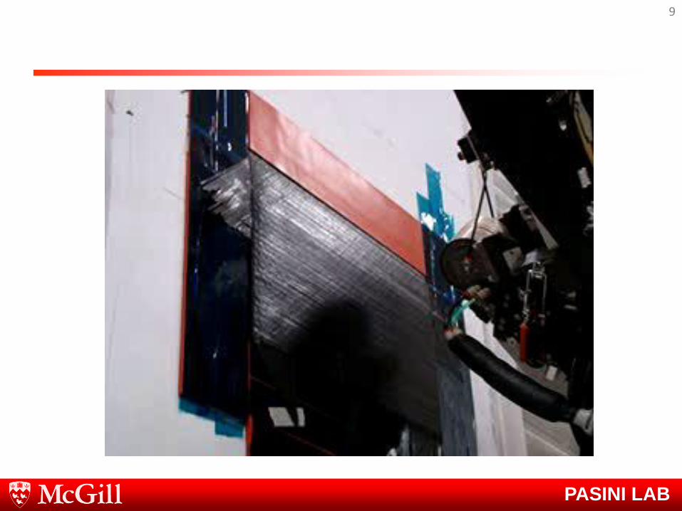
Automated Fiber Placement machine (AFP)
10
• Robotic arm which places strips of material side-by-side to create a band
• Lays down bands to create the laminate
• Pros:
• High manufacturing flexibility
• Fully automated process
• Speeds up the layup time
• Ideal for large structures
• Cons:
• Defects produced during the manufacturing
Source: Coriolis website.
PASINI LAB
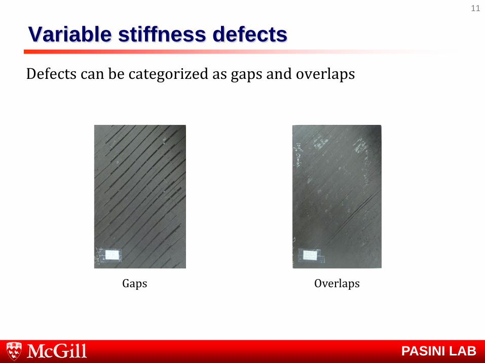
Variable stiffness defects
Defects can be categorized as gaps and overlaps
11
Overlaps Gaps

PASINI LAB
Talk objectives
• Exploiting variable stiffness design to improve mechanical efficiency of lightweight laminate composites
• Development of a simulation toolbox to capture the mechanical impact of AFP defects
• Incorporating the effect of defects in the analysis and optimization of variable stiffness composite laminates
12
PASINI LAB
Lab Expertise
13
Microarchitectured Materials
PASINI LAB
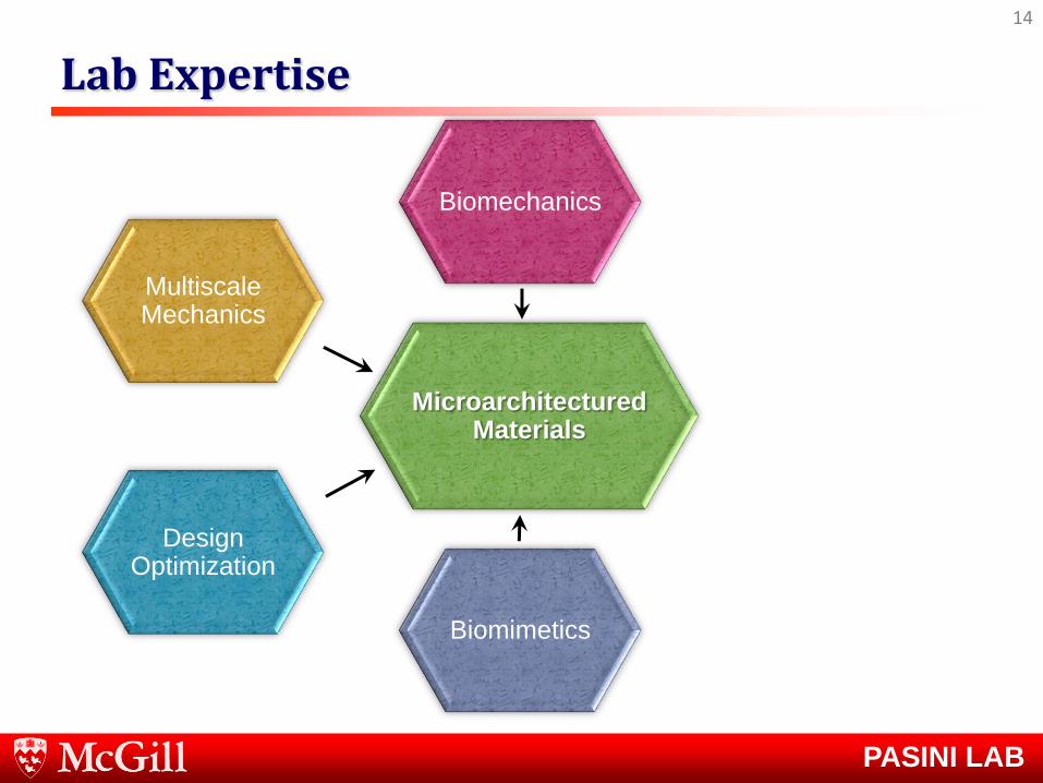
Lab Expertise
14
Microarchitectured Materials
Biomechanics
Multiscale Mechanics
Design Optimization
Biomimetics
PASINI LAB
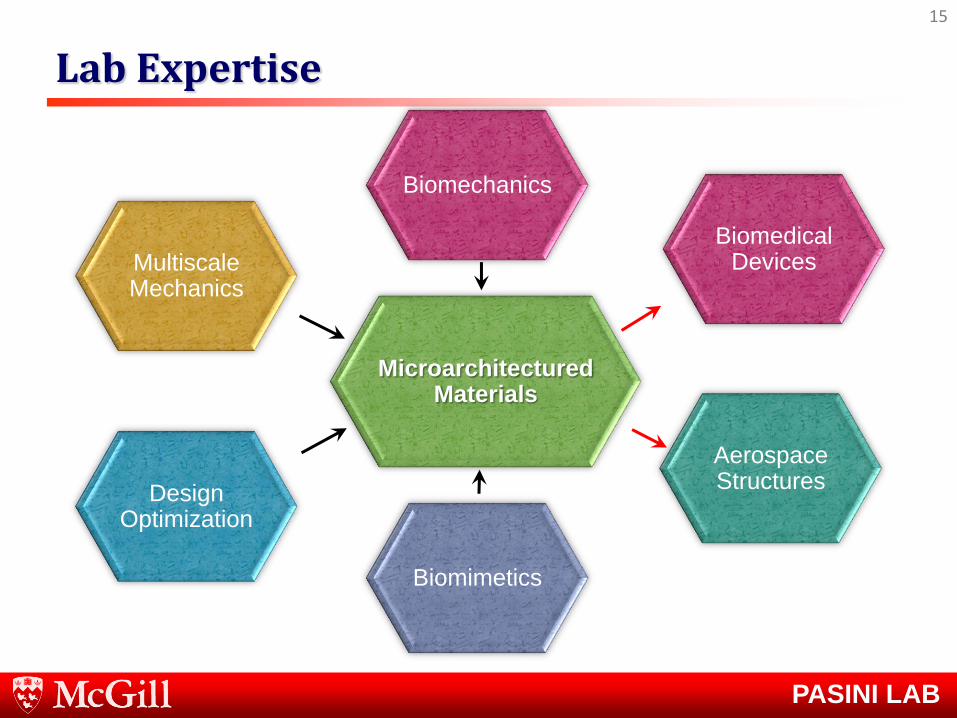
Lab Expertise
15
Microarchitectured Materials
Biomechanics
Multiscale Mechanics
Design Optimization
Biomimetics
Aerospace Structures
Biomedical Devices

PASINI LAB
Current Projects
16
Multiphysics of lattice materials
AFP variable stiffness laminate composites
Lattice stent-like devices
Cellular hip replacement implants
Ultralightweight lattice panels via additive
manufacturing
Plant cellular tissue inspired materials

PASINI LAB
Talk objectives
• Exploiting variable stiffness design to improve mechanical efficiency of lightweight laminate composites
• Development of a simulation toolbox to capture the mechanical impact of AFP defects
• Incorporating the effect of defects in the analysis and optimization of variable stiffness composite laminates
17

PASINI LAB
Talk objectives
• Exploiting variable stiffness design to improve mechanical efficiency of lightweight laminate composites
• Development of a simulation toolbox to capture the mechanical impact of AFP defects
• Incorporating the effect of defects in the analysis and optimization of variable stiffness composite laminates
18

PASINI LAB
Curvilinear fiber path
19
1 0 1[ | | ]T T T
• Constant curvature fiber path is used as the reference fiber path*
• The reference fiber path is shifted to manufacture the whole laminate
• 10 x 16 in plate is considered as a case study
T0
T1 y
x
O ρ
T1
*Blom et al., Journal of Composite Materials (2009).
Free Free
PASINI LAB
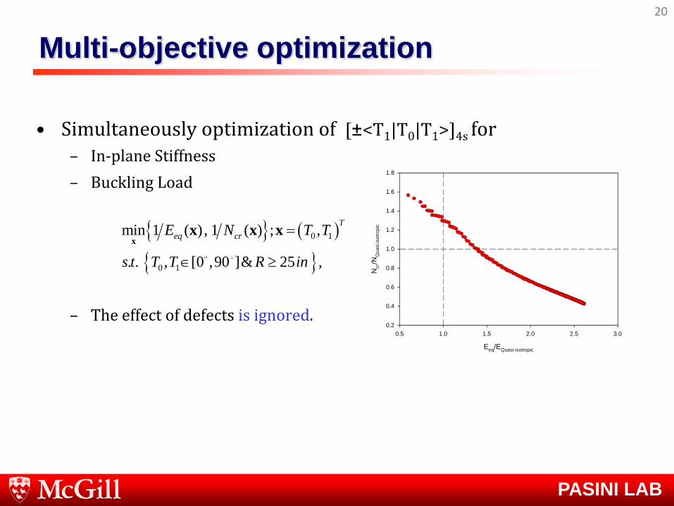
Multi-objective optimization
• Simultaneously optimization of [±<T1|T0|T1>]4s for
– In-plane Stiffness
– Buckling Load
– The effect of defects is ignored.
20
0 1
0 1
min ; ,
. . , [0 ,90 ]
1 (
&
), ( )
25
1
,
T
eq crE N T T
s t T T R in
xx x x
Eeq
/EQuasi-isotropic
0.5 1.0 1.5 2.0 2.5 3.0
Ncr/N
Qu
asi-
iso
tro
pic
0.2
0.4
0.6
0.8
1.0
1.2
1.4
1.6
1.8
PASINI LAB
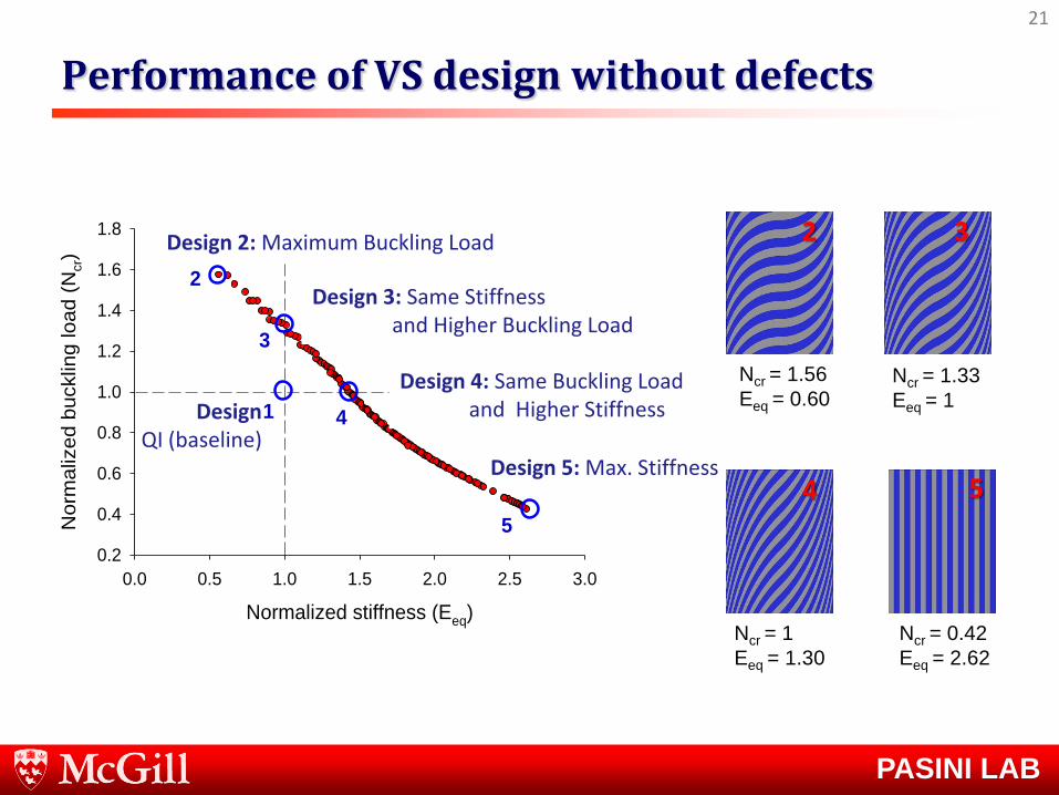
Performance of VS design without defects
21
Normalized stiffness (Eeq)
0.0 0.5 1.0 1.5 2.0 2.5 3.0
Norm
aliz
ed b
ucklin
g load (
Ncr)
0.2
0.4
0.6
0.8
1.0
1.2
1.4
1.6
1.8
2
1
3
4
5
Design QI (baseline)
Design 3: Same Stiffness and Higher Buckling Load
Design 5: Max. Stiffness
Design 4: Same Buckling Load and Higher Stiffness
Design 2: Maximum Buckling Load 2 3
4 5
Ncr = 1.56
Eeq = 0.60 Ncr = 1.33
Eeq = 1
Ncr = 1
Eeq = 1.30
Ncr = 0.42
Eeq = 2.62

PASINI LAB
Variable stiffness defects
Defects can be categorized as gaps and overlaps
22
Overlaps Gaps

PASINI LAB
Talk objectives
• Exploiting variable stiffness design to improve mechanical efficiency of lightweight laminate composites
• Development of a simulation toolbox to capture the mechanical impact of AFP defects
• Incorporating the effect of defects in the analysis and optimization of variable stiffness composite laminates
23

PASINI LAB
AFP defects analysis toolbox
24
A lamina with gaps
0
0.257
0.386
0.515
0.644
0.772
0.901
1.030
1.158
0.129
Mesh generation Stress in y-direction

PASINI LAB
25
Normalized Stiffness
0.0 0.5 1.0 1.5 2.0 2.5 3.0
Norm
aliz
ed b
ucklin
g load
0.2
0.4
0.6
0.8
1.0
1.2
1.4
1.6
1.8
2.0
Design 2
Design 3
Ignoring gaps/overlaps
Overlaps
Gaps
Normalized buckling load
Normalized buckling load
Normalized buckling load
Design 2 1.56 1.40 1.88
Design 3 1.33 1.16 1.67
The effect of defects on VS laminates performance
PASINI LAB
Talk objectives
• Exploiting variable stiffness design to improve mechanical efficiency of lightweight laminate composites
• Development of a simulation toolbox to capture the mechanical impact of AFP defects
• Incorporating the effect of defects in the analysis and optimization of variable stiffness composite laminates
26

PASINI LAB
Multi-objective optimization including defects
• Simultaneously maximize objectives of [±<T1|T0|T1>]4s:
• In-plane Stiffness.
• Buckling Load.
• The effect of defects is considered during the optimization process.
• Defect layer method is used.
27
0 1
0 1
min ; ,
. . , [0 ,90 ]
1 (
&
), ( )
25
1
,
T
eq crE N T T
s t T T R in
xx x x

PASINI LAB
Impact on the mechanical properties
28
Normalized in-plane stiffness
0.0 0.5 1.0 1.5 2.0 2.5 3.0
No
rma
lize
d b
ucklin
g lo
ad
0.2
0.4
0.6
0.8
1.0
1.2
1.4
1.6
1.8
2.0
Ignoring defects
Gaps
Overlaps
PASINI LAB
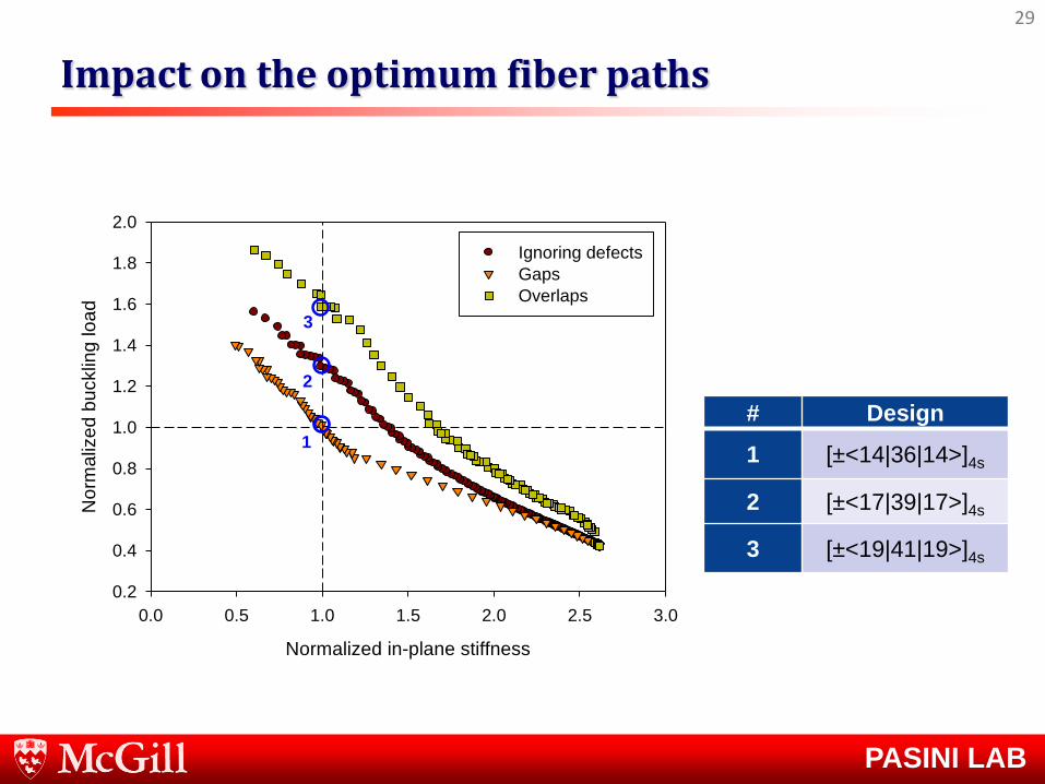
Impact on the optimum fiber paths
29
Normalized in-plane stiffness
0.0 0.5 1.0 1.5 2.0 2.5 3.0
No
rma
lize
d b
ucklin
g lo
ad
0.2
0.4
0.6
0.8
1.0
1.2
1.4
1.6
1.8
2.0
Ignoring defects
Gaps
Overlaps
1
2
3
# Design
1 [±<14|36|14>]4s
2 [±<17|39|17>]4s
3 [±<19|41|19>]4s
PASINI LAB
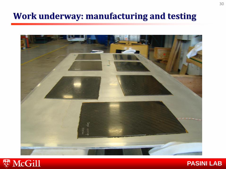
Work underway: manufacturing and testing
30

PASINI LAB
Work underway: manufacturing and testing
31
Design 2: highest buckling load
compared to the baseline

PASINI LAB
Concluding remarks
• Exploiting variable stiffness design to improve mechanical efficiency : 56% improvement in buckling load
• Development of a simulation toolbox to capture the mechanical impact of AFP defects: • 88% improvement in buckling load for laminates with overlaps
• 40% improvement in buckling load for laminates with gaps
• Optimization of variable stiffness composite laminates including defects
32

PASINI LAB
Concluding remarks
• Exploiting variable stiffness design to improve mechanical efficiency : 56% improvement in buckling load
• Development of a simulation toolbox to capture the mechanical impact of AFP defects: • 88% improvement in buckling load for laminates with overlaps
• 40% improvement in buckling load for laminates with gaps
• Optimization of variable stiffness composite laminates including defects
A lighter structure, more fuel efficient and sustainable
33

PASINI LAB
Questions ?
34
PASINI LAB
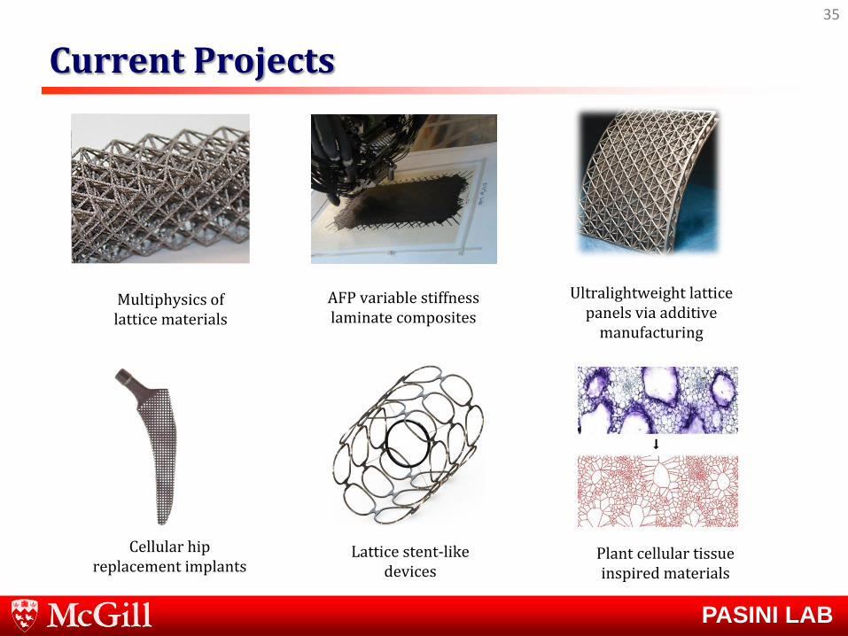
Current Projects
35
Multiphysics of lattice materials
AFP variable stiffness laminate composites
Lattice stent-like devices
Cellular hip replacement implants
Ultralightweight lattice panels via additive
manufacturing
Plant cellular tissue inspired materials

PASINI LAB
Overlap-modified defect element
• A single layer [0]T laminate.
• An overlap is at the plate center and along fiber direction.
• Material and strength properties are the same as regular composite material.
• The effective element thickness is the average of the thickness in the element.
36
y
x
y
x
PASINI LAB
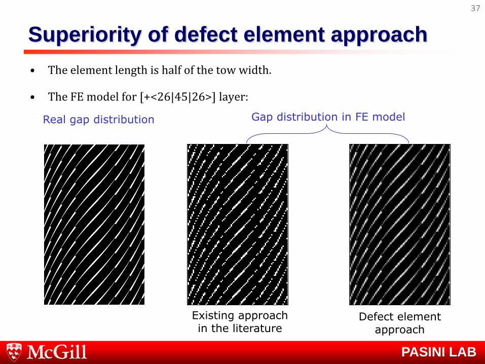
Superiority of defect element approach
• The element length is half of the tow width.
• The FE model for [+<26|45|26>] layer:
37
Real gap distribution
Defect element approach
Existing approach in the literature
Gap distribution in FE model

PASINI LAB
FE model for capturing defects (module 3)
• A novel approach, defect layer, is proposed to capture defects precisely.
– Gap-modified defect layer.
– Overlap-modified defect layer.
• Each element may contain any defect area percentage.
• Fiber orientation at the element midpoint is calculated and used as the element fiber orientation.
38
PASINI LAB
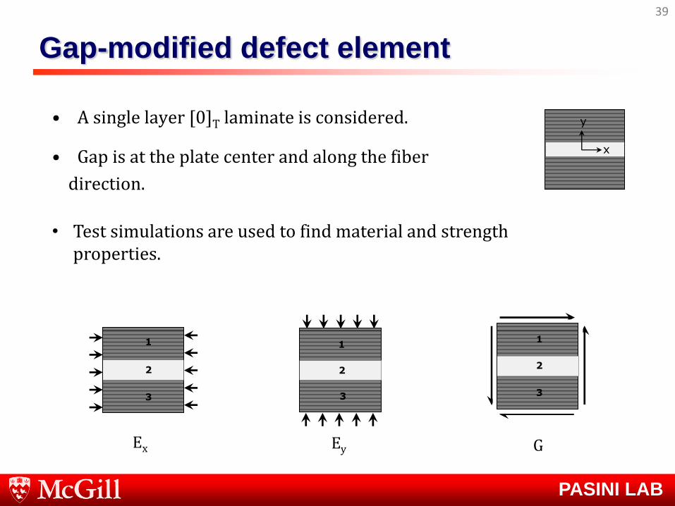
Gap-modified defect element
• A single layer [0]T laminate is considered.
• Gap is at the plate center and along the fiber
direction.
39
y
x
1
2
3
1
2
3
1
2
3
Ex Ey G
• Test simulations are used to find material and strength properties.
PASINI LAB
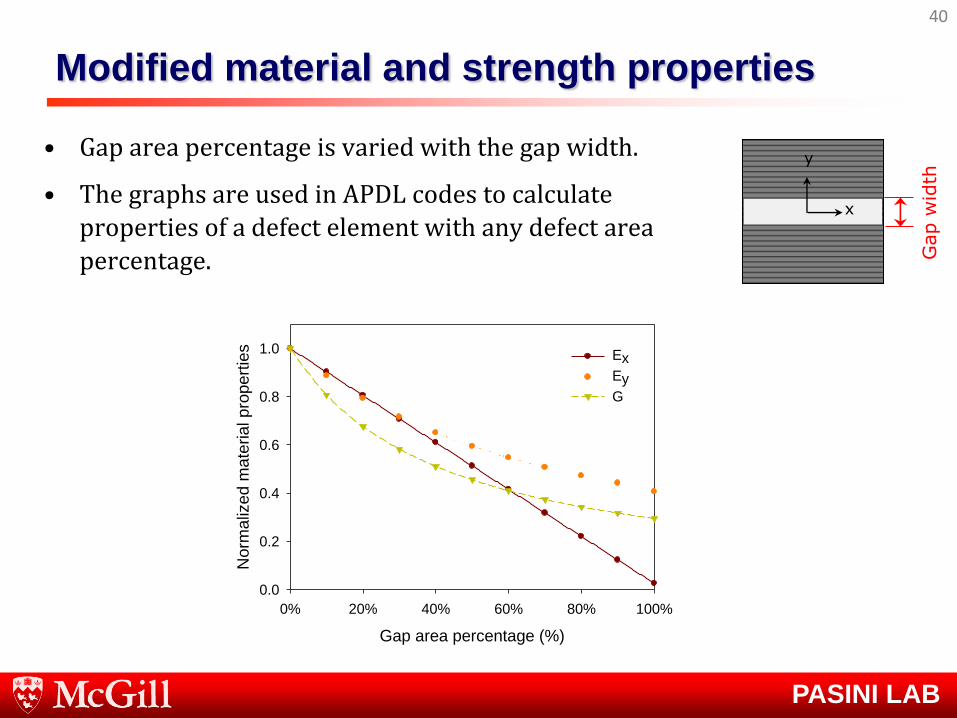
Modified material and strength properties
40
Gap area percentage (%)
0% 20% 40% 60% 80% 100%
Norm
aliz
ed m
ate
rial pro
pert
ies
0.0
0.2
0.4
0.6
0.8
1.0 Ex
Ey
G
• Gap area percentage is varied with the gap width.
• The graphs are used in APDL codes to calculate properties of a defect element with any defect area
percentage.
y
x
Gap w
idth
PASINI LAB
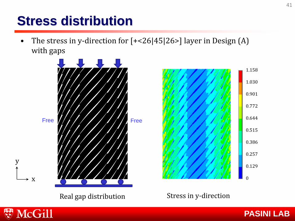
Stress distribution
• The stress in y-direction for [+<26|45|26>] layer in Design (A) with gaps
41
Real gap distribution Stress in y-direction
0
0.257
0.386
0.515
0.644
0.772
0.901
1.030
1.158
0.129
Free Free
x
y