automated monitoring of exceptional civil structures –case
TRANSCRIPT

IABSE Conference 2018 – Engineering the Past, to Meet the Needs of the Future June 25-27 2018, Copenhagen, Denmark
1
Automated monitoring of exceptional civil structures – Case studies
Niculin Meng, Colm O’Suilleabhain Mageba SA, Bulach, Switzerland
Contact: [email protected]
Abstract Maintenance of engineering structures, and the associated required inspection activities, are a significant cause of expense and of disruption to service, so the use of constantly developing modern technology such as structural health monitoring (SHM) systems should always be considered. And during the construction stage too, the use of such systems can offer many benefits. This is especially true of exceptional civil structures, where design and construction are particularly non-standard, and where inspection and maintenance work often presents particular challenges. This is illustrated with reference to recent and ongoing projects relating to an offshore oil platform, the enormous solar panel roof canopy of an iconic opera building, and a 700m-long cable stayed bridge.
Keywords: SHM; monitoring; exceptional structures; offshore platforms; buildings; bridges.
1 Introduction Exceptional civil structures, the design and construction of which are particularly non-standard, can benefit greatly from the use of modern structural health monitoring technology in facilitating and optimising their construction. And since the inspection and maintenance of exceptional structures often presents particular challenges, SHM can also continue to play an important role throughout such structures’ life cycles.
In the case of offshore platforms, for instance, access is much more limited than is typically the case on a structure that is located on land, and as a result, much more complicated and expensive to arrange and provide. This limited access, coupled with the high value of offshore platform operations and the corresponding importance of avoiding interruptions to these, makes reliability a key concern for platform operators. This is not only true in relation to inspection and maintenance activities, but also in relation to replacement of key
“wear” components which might be expected to require replacement during the main structure’s service life – the longer the life of the key components, the lower the need to carry out expensive and disruptive replacement works.
In such cases, SHM systems can play an especially valuable role in inspection and maintenance, by making very detailed information about critical parameters, and the status and condition of key components, available in real time. Of course, the recorded data can also be automatically analysed to suit the operator’s needs, and systems can be configured to immediately issue alarm messages when previously defined values of key parameters are exceeded. Such functionality, which can be used to optimally plan and carry out inspection and maintenance work, and the confidence such systems can provide in the ongoing condition and reliability of monitored structures, can be enormously beneficial to owners and operators of exceptional civil structures.
IABSE Conference 2018 – Engineering the Past, to Meet the Needs of the Future June 25-27 2018, Copenhagen, Denmark
2
2 The bearings and integrated SHM system of the Johan Sverdrup offshore platform facility
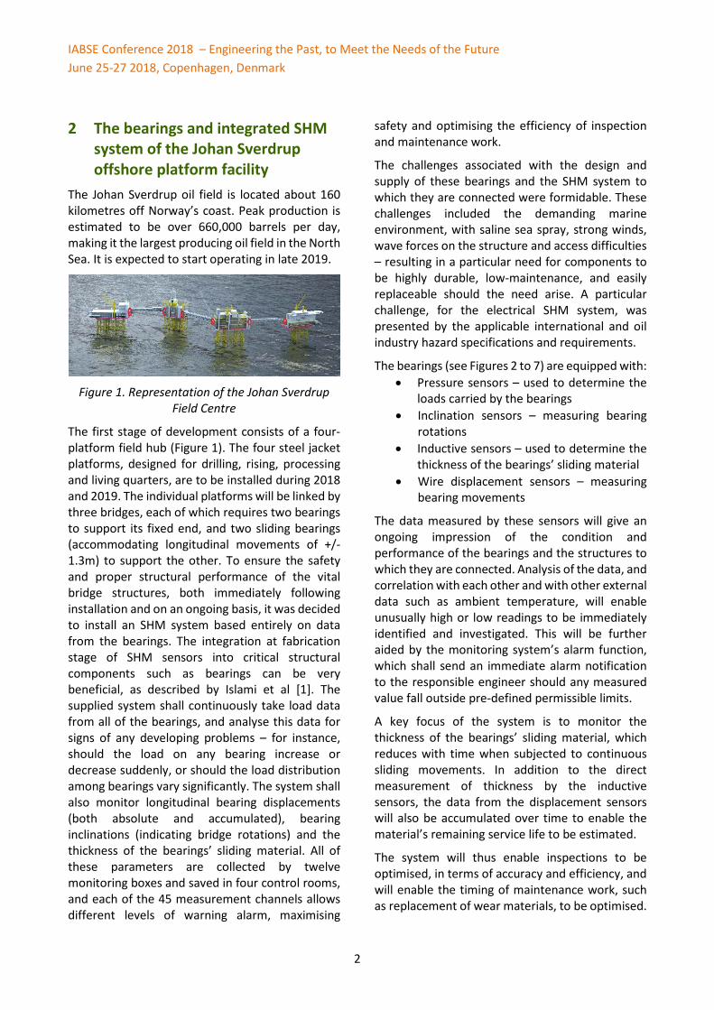
The Johan Sverdrup oil field is located about 160 kilometres off Norway’s coast. Peak production is estimated to be over 660,000 barrels per day, making it the largest producing oil field in the North Sea. It is expected to start operating in late 2019.
Figure 1. Representation of the Johan Sverdrup
Field Centre
The first stage of development consists of a four-platform field hub (Figure 1). The four steel jacket platforms, designed for drilling, rising, processing and living quarters, are to be installed during 2018 and 2019. The individual platforms will be linked by three bridges, each of which requires two bearings to support its fixed end, and two sliding bearings (accommodating longitudinal movements of +/- 1.3m) to support the other. To ensure the safety and proper structural performance of the vital bridge structures, both immediately following installation and on an ongoing basis, it was decided to install an SHM system based entirely on data from the bearings. The integration at fabrication stage of SHM sensors into critical structural components such as bearings can be very beneficial, as described by Islami et al [1]. The supplied system shall continuously take load data from all of the bearings, and analyse this data for signs of any developing problems – for instance, should the load on any bearing increase or decrease suddenly, or should the load distribution among bearings vary significantly. The system shall also monitor longitudinal bearing displacements (both absolute and accumulated), bearing inclinations (indicating bridge rotations) and the thickness of the bearings’ sliding material. All of these parameters are collected by twelve monitoring boxes and saved in four control rooms, and each of the 45 measurement channels allows different levels of warning alarm, maximising
safety and optimising the efficiency of inspection and maintenance work.
The challenges associated with the design and supply of these bearings and the SHM system to which they are connected were formidable. These challenges included the demanding marine environment, with saline sea spray, strong winds, wave forces on the structure and access difficulties – resulting in a particular need for components to be highly durable, low-maintenance, and easily replaceable should the need arise. A particular challenge, for the electrical SHM system, was presented by the applicable international and oil industry hazard specifications and requirements.
The bearings (see Figures 2 to 7) are equipped with: • Pressure sensors – used to determine the
loads carried by the bearings • Inclination sensors – measuring bearing
rotations • Inductive sensors – used to determine the
thickness of the bearings’ sliding material • Wire displacement sensors – measuring
bearing movements
The data measured by these sensors will give an ongoing impression of the condition and performance of the bearings and the structures to which they are connected. Analysis of the data, and correlation with each other and with other external data such as ambient temperature, will enable unusually high or low readings to be immediately identified and investigated. This will be further aided by the monitoring system’s alarm function, which shall send an immediate alarm notification to the responsible engineer should any measured value fall outside pre-defined permissible limits.
A key focus of the system is to monitor the thickness of the bearings’ sliding material, which reduces with time when subjected to continuous sliding movements. In addition to the direct measurement of thickness by the inductive sensors, the data from the displacement sensors will also be accumulated over time to enable the material’s remaining service life to be estimated.
The system will thus enable inspections to be optimised, in terms of accuracy and efficiency, and will enable the timing of maintenance work, such as replacement of wear materials, to be optimised.

IABSE Conference 2018 – Engineering the Past, to Meet the Needs of the Future June 25-27 2018, Copenhagen, Denmark
3
Figure 2. Illustration showing the design of a sliding bearing (longitudinal movement capacity +/- 1.3 m)
Figure 3. Locations of various sensors on sliding bearings
Figure 4. Installation of sensors on a sliding
bearing with connection to Signal Conversion Box
Figure 5. Wire displacement sensor
Figure 6. Inclinometer on side of a bearing
Figure 7. Bearing for fixed end of one bridge, with
stainless steel conduits for cables to sensors

IABSE Conference 2018 – Engineering the Past, to Meet the Needs of the Future June 25-27 2018, Copenhagen, Denmark
4
3 The roof canopy of the Greek National Opera House
The Greek National Opera (Figure 8), with an area of 33,000 m² and a main 1400-seat theatre, is one of several architectural masterpieces of the new Stavros Niarchos Foundation Cultural Centre in Athens. Perhaps the building’s most impressive and distinguishing feature is its canopy roof, an enormous truss structure of area 10,000 m2 that is elevated high above the main structure on a grid of 30 columns. The truss structure (Figure 9) is covered by solar panels, supporting the centre’s energy self-sufficiency. To stabilise the canopy structure against the strong wind forces arising in this coastal location, by damping all vertical vibrations, the connection of the canopy to each column head is equipped with two shock absorbers and four spring devices, arranged around the column head as shown in Figure 10. To monitor the performance of the total 60 shock absorbers and 120 spring devices, every device is connected to a permanent Robo-Control structural health monitoring system. An example of graphical data (pressures and movements, correlated with temperature) from a one-year period is presented in Figure 11. This demonstrates excellent correlation throughout the period, providing confidence in the condition and performance of the devices.
Figure 8. The Greek National Opera, with its
imposing roof canopy structure of area 10,000 m2
Figure 9. View inside the roof canopy, showing truss structure between top and bottom skins
Figure 10. Vibrations at each of the 30 column heads are damped by two Reston-SA shock
absorbers and four Reston-SP spring devices
A particular challenge was presented by the construction of the canopy structure, with its weight of 5000 t. The structure was constructed on scaffolding under its entire area (some placed on the roof of the main building, some on the ground below) – scaffolding which, of course, required to be removed once the canopy construction was completed. To enable the scaffolding to be removed, the entire canopy needed to be lifted slightly. To avoid the need for conventional heavy lifting, an alternative solution was developed using the 30 column head assemblies of shock absorbers and spring devices. By injecting compressible elastomer into the spring devices in a very controlled manner (Figures 12 to 15), ensuring even load distribution at all times, it was possible to lift the roof enough to remove the scaffolding after just ten days – a fraction of the time that would have been needed for conventional heavy lifting, and at a fraction of the cost.

IABSE Conference 2018 – Engineering the Past, to Meet the Needs of the Future June 25-27 2018, Copenhagen, Denmark
5
Figure 11. Sample of SHM system output showing 12 months of data from the shock absorbers and springs at one column head, demonstrating excellent correlation between pressure, movements and temperature
Figure 12. Installation of temporary injection
circuit at a column head assembly to lift canopy
Figure 13. Use of monitoring system during
simultaneous injection at 20% of column heads
Figure 14. After seven days of injection, the roof
canopy lifts off the scaffolding
Figure 15. After 10 days of injection, desired height reached and scaffolding could be safely removed

IABSE Conference 2018 – Engineering the Past, to Meet the Needs of the Future June 25-27 2018, Copenhagen, Denmark
6
4 The Kota Chambal Bridge, India The Kota Chambal Bridge, recently constructed in Rajasthan, northern India, carries a bypass highway of the city of Kota over the Chambal River, just outside the city. It has a main span of 350 m, spanning the full width of the river to avoid any impact on wildlife in this designated sanctuary area, and lateral spans of 175 m at either end.
The bridge (Figure 16), built by a Hyundai-Gammon joint venture, is the first axial suspension cable-stayed bridge ever built in India, and its geometry presented particular design and construction challenges, so it was decided to use an SHM system to assist already during the bridge construction phase, and subsequently, permanently, for inspection and maintenance purposes.
Figure 16. The Chambal Bridge during construction
The SHM system was designed to serve different purposes at different stages in the bridge’s life cycle – first during the construction stage, and then during its service life. This required the system to be modified, in particular in relation to sensor specifics and layout, in 2017.
The sensor functionality varied as the structure was built, as follows:
o During bridge construction phase (temporary): • Accelerometers on cables: Vibration
frequency and force in cable • 3D structural accelerometers at deck:
Measuring frequencies of deck vibration and determining natural frequencies
• 2D Inclinometers at pier: Inclination of pylon during construction phase
• 2D Inclinometers at deck: Inclination of deck during construction phase
• Air temperature and humidity: For correlation with structural parameters
o During the bridge’s service life (permanent): • Accelerometers on cables: Vibration
frequency and force in cable • Structural accelerometers at pier and deck
(2D and 3D): Vibration frequency • 2D Inclinometers at pier: Inclination of
pylon when bridge in service • Displacement sensors at expansion joint:
Movement of deck at its end • Wind speed and direction at piers and
deck: For correlation with structural parameters
• Air temperature and humidity: For correlation with structural parameters
A key focus of the system is the bridge’s stay cables, whose performance is critical to the construction and service life of the structure. The cable monitoring part of the system was designed, with accelerometers attached to selected cables (Figure 17), to ensure that the structure’s load distribution is not distorted by thermal, traffic, seismic or any other forces, and to provide information on the cables' damping coefficients and remaining service lives.
Figure 17. Forced vibration of stay cable with
accelerometer during bridge construction phase
The permanent system is designed to continuously record the dynamic movements and stresses in the bridge, along with the environmental factors (including traffic, seismic, wind, etc.,) that may cause or affect these. It is also designed to, in real time, process, analyse, and interpret the data, display the data and analysis results, and provide warnings when there is a safety risk.

IABSE Conference 2018 – Engineering the Past, to Meet the Needs of the Future June 25-27 2018, Copenhagen, Denmark
7
The 2D inclinometers at the pylons measure inclinations at high resolution, enabling deviations due to non-uniform load distribution or cable malfunction to be identified. Linear displacements are measured at the expansion joints at both ends of the bridge to an accuracy of less than 0.1 mm – for checking the designed displacement values and observing the behaviour of the bridge under varying environmental and traffic conditions. Automated dynamic identification is included, to determine the natural frequency of the structure and of the stay cables (Figure 18).
Figure 18. Stay cable natural frequency
The determined frequency values are displayed in time-frequency graphs, in order to continuously record the behaviour of the structure and detect any possible damage, and the values are used to derive the tension forces in the cables (Figure 19).
Figure 20 presents the results of verticality measurements (inclination to X and Y axes) of one of the bridge’s pylons. These measurements are important for the correct execution of works related to load distribution at each side of the pylon. A non-balanced situation would mean an increase in inclination (longitudinally) of the pylon for the sensors positioned both at the top and at mid-height of the pylon. The figure shows that, during the six-month period covered, tilting in the longitudinal direction is always due to temperature or to temporary unbalanced loading scenarios resulting from the addition of cast-in-place segments to the main span. Analysis of the transverse direction shows that changes here are due not only to temperature but also to wind and to loading from the crane which is attached to the pylon during construction. In both cases, the daily inclinations due to night and day temperature fluctuations are clearly visible.
Figure 19. First natural frequency of one stay cable (above), and the derived tension force (below)
2 4 6 8 10 12
-210
-200
-190
-180
-170
-160
-150
-140
-130
-120
FDD - Singular values
Frequency [Hz]
SVD
.[deb
]
1
1.05
1.1
1.15
1.2q y
Freq
uenc
y [H
z]
Freq 1 cable M11
27/09/16 16/11/16 05/01/17 24/02/17 15/04/17
6500
7000
7500
8000
Date
Forc
e [k
N]
Force 1 cable M11

IABSE Conference 2018 – Engineering the Past, to Meet the Needs of the Future June 25-27 2018, Copenhagen, Denmark
8
Figure 20. Monitoring of pylon verticality to support bridge’s construction by ensuring right load distribution
5 Conclusions Structural health monitoring of exceptional structures, such as offshore oil platforms, iconic buildings and cable-supported bridges, can offer great benefits during construction and in relation to the critically important inspection and maintenance activities that such structures especially require. As demonstrated by the great diversity in the case studies presented, a suitable SHM system can be designed and supplied by an experienced specialist manufacturer for virtually any application. As also illustrated, it may be very beneficial to consider the need for, and the needs of, an SHM system early in the structure’s design and construction process. This is especially true where a system’s sensors should ideally be pre-integrated in the factory into key structural components such as bearings – a process which is optimised if the SHM supplier is also an experienced manufacturer of such structural components.
References [1] Islami K., Meng N. and O’Suilleabhain, C.
Smart bridge components (expansion joints, bearings and seismic devices) for intelligent infrastructure. Proceedings of the 19th IABSE Congress, Stockholm, Sweden; 2016.
24
26
28Temperature vs. Date
Tem
pera
ture
[°C
]
Temp 1
20
40
60Relative Humidity vs. Date
Hum
idity
[%]
RH 1
-0.2
-0.1
Longitudinal Inclination vs. Date
Incl
. [de
g]
16/11/2017 26/11/16
-0.1
-0.05
0Trasversal Inclination vs. Date
Incl
. [de
g]