automatic code generation from uml class and statechart ... · systems has encouraged the use of...
TRANSCRIPT

Automatic Code Generation From
UML Class and Statechart Diagrams
Graduate School of Systems and Information Engineering
University of Tsukuba
November 2005
Iftikhar Azim Niaz
Automatic Code Generation From
UML Class and Statechart Diagrams
Iftikhar Azim Niaz
November 2005
A dissertation submitted in partial fulfillment of the requirements for
the degree of Doctor of Philosophy in Engineering
Computer Science
Doctoral Program in Engineering
University of Tsukuba, Japan

Dedicated to my parents,
wife Fariha and our children, Rameen and Sarmad
for their love, encouragement and support
1
Abstract
The emergence of Unified Modeling Language (UML) as a standard for modeling
systems has encouraged the use of automated software tools that facilitate the
development process from analysis through coding. In UML, the static structure of
classes in a system is represented by a class diagram while the dynamic behavior
of the classes is represented by a set of statechart diagrams. To facilitate the
software development process, it would be ideal to have tools that automatically
generate or help to generate executable code from the models.
In the present study, an effort has been made to find methods to automatically
generate executable code from the UML class and statechart diagrams. An object-
oriented approach has been proposed to generate executable implementation code
from UML class and statechart diagrams in an object-oriented programming
language. The generated code contains the structural as well as behavioral code for
all the classes of the application model. A new approach, collaborator object, has
been proposed to implement the UML statechart diagram. States are represented as
objects and events as their methods. The hierarchical and concurrent substates are
implemented by using the concept of object composition and delegation.
An automatic code generating system, JCode, has also been developed that
implements the proposed method and automatically generates executable Java code
from the specifications of the UML class and statechart diagrams. A comparison
with Rhapsody and OCode shows that the code generated by JCode is much more
compact, efficient and readable than that of Rhapsody and OCode.

2
Contents
List of Figures 5
List of Tables 8
1 Introduction 9
1.1 Unified Modeling Language (UML) . . . . . . . . . . . . . . . 9
1.2 Motivation . . . . . . . . . . . . . . . . . . . . . . . . . . . . 10
1.3 Goals and Objectives . . . . . . . . . . . . . . . . . . . . . . . 11
1.4 Organization . . . . . . . . . . . . . . . . . . . . . . . . . . . 11
2 Approaches To Implement Statechart Diagram 13
2.1 Switch Statement . . . . . . . . . . . . . . . . . . . . . . . . . 15
2.2 Helper Object . . . . . . . . . . . . . . . . . . . . . . . . . . . 17
2.3 Collaborator Object . . . . . . . . . . . . . . . . . . . . . . . . 21
3 Combining Class Diagrams and Statechart Diagrams 28
3.1 The Dishwasher System . . . . . . . . . . . . . . . . . . . . . 28
3.2 Combining Class and Statechart Diagrams . . . . . . . . . . . . 33
3.2.1 Class Diagram Module . . . . . . . . . . . . . . . . . . 36
3.2.2 Statechart Diagram Module . . . . . . . . . . . . . . . 37
3.2.3 Code Generation Module . . . . . . . . . . . . . . . . 39
3
4 Automatic Code Generating System: JCode 43
4.1 Main Module . . . . . . . . . . . . . . . . . . . . . . . . . . . 45
4.2 CDAnalyzer . . . . . . . . . . . . . . . . . . . . . . . . . . . . 46
4.3 CDTransformer . . . . . . . . . . . . . . . . . . . . . . . . . . 48
4.4 SCAnalyzer . . . . . . . . . . . . . . . . . . . . . . . . . . . . 49
4.5 SCTransformer . . . . . . . . . . . . . . . . . . . . . . . . . . 52
4.6 Code Generator . . . . . . . . . . . . . . . . . . . . . . . . . . 55
5 Implementing Other Features of Statechart Diagram 61
5.1 Fork and Join . . . . . . . . . . . . . . . . . . . . . . . . . . . 61
5.1.1 Implementing Fork and Join . . . . . . . . . . . . . . . 63
5.2 History State . . . . . . . . . . . . . . . . . . . . . . . . . . . 64
5.2.1 Implementing History . . . . . . . . . . . . . . . . . . 66
6 Comparison with Rhapsody and OCode 68
6.1 Watch Application . . . . . . . . . . . . . . . . . . . . . . . . 69
6.2 Microwave System . . . . . . . . . . . . . . . . . . . . . . . . 71
6.3 Dishwasher System . . . . . . . . . . . . . . . . . . . . . . . 73
6.4 Air Conditioner System . . . . . . . . . . . . . . . . . . . . . . 74
6.5 Cassette Player System . . . . . . . . . . . . . . . . . . . . . . 75
6.6 Test Device Application . . . . . . . . . . . . . . . . . . . . . 76
6.7 Comparison Results . . . . . . . . . . . . . . . . . . . . . . . . 78
6.7.1 Compact Code . . . . . . . . . . . . . . . . . . . . . . 78
6.7.2 Efficient Code . . . . . . . . . . . . . . . . . . . . . . 80
4
7 Related Work 84
7.1 Implementing Class Diagram . . . . . . . . . . . . . . . . . . . 84
7.2 Implementing Statechart with Switch Statement . . . . . . . . . 85
7.3 Implementing Statechart with Design Pattern . . . . . . . . . . 85
7.4 Other Approaches to Implement Statechart . . . . . . . . . . . 89
8 Conclusions
92
Acknowledgements
94
Bibliography
96
Author Publications List
99
5
List of Figures
2.1 Statechart for air conditioner . . . . . . . . . . . . . . . . . . . . . 15
2.2 Code generated by switch statement approach . . . . . . . . . . . . 16
2.3 Code generated by helper object approach . . . . . . . . . . . . . . 19
2.4 Implementation structure of helper object approach . . . . . . . . . 21
2.5 Code generated by collaborator object approach . . . . . . . . . . . 24
2.6 Implementation structure of collaborator object approach . . . . . . 26
3.1 Class diagram for the dishwasher system . . . . . . . . . . . . . . . 29
3.2 Statechart of Dishwasher class . . . . . . . . . . . . . . . . . . . . 30
3.3 Statechart of Tank class . . . . . . . . . . . . . . . . . . . . . . . . 31
3.4 Statechart of Jet class . . . . . . . . . . . . . . . . . . . . . . . . . 32
3.5 Statechart of Heater class . . . . . . . . . . . . . . . . . . . . . . . 32
3.6 Overview of the JCode system . . . . . . . . . . . . . . . . . . . . 35
3.7 Class diagram specifications of dishwasher system in DSL format . . 36
3.8 Statechart DSL filenames for classes of dishwasher system . . . . . 37
3.9 Statechart specifications of Dishwasher class in DSL format . . . . . 37
3.10 Part of the updated state table for statechart of Jet class . . . . . . . 38
3.11 Part of the updated state table for statechart of Dishwasher class . . . 38
3.12 Part of the updated class table for dishwasher system . . . . . . . . . 39
6
3.13 Generated code for the application class of dishwasher system . . . . 40
3.14 Part of the generated code for the Dishwasher class . . . . . . . . . 42
4.1 Class diagram for the air conditioner system . . . . . . . . . . . . . 44
4.2 Statechart of AirCon class . . . . . . . . . . . . . . . . . . . . . . . 44
4.3 Structure of the JCode system . . . . . . . . . . . . . . . . . . . . . 45
4.4 Class diagram specifications of air conditioner system in DSL format 46
4.5 Part of the ClassInfo table for air conditioner system . . . . . . . . . 48
4.6 Statechart DSL filenames for classes of air conditioner system . . . . 49
4.7 Statechart specifications of AirCon class in DSL format . . . . . . . 50
4.8 Part of the state table for statechart of AirCon class . . . . . . . . . 52
4.9 Part of the updated state table for statechart of AirCon class . . . . . 54
4.10 Part of the updated ClassInfo table for air conditioner system . . . . 54
4.11 Generated code for the application class of air conditioner system . . 55
4.12 Generated code for the DisplayInterface class . . . . . . . . . . . . 56
4.13 Part of the generated code for the AirCon class . . . . . . . . . . . . 60
5.1 Statechart for Test class containing Fork and Join . . . . . . . . . . 62
5.2 Part of the generated code for the Test class . . . . . . . . . . . . . 64
5.3 Statechart for CPlayer class containing history state . . . . . . . . . 65
5.4 Part of the generated code for the CPlayer class . . . . . . . . . . . 67
6.1 Class diagram for the watch application . . . . . . . . . . . . . . . 69
6.2 Statechart of Watch class containing hierarchical states . . . . . . . . 70
6.3 Class diagram for the microwave system . . . . . . . . . . . . . . . 72

7
6.4 Statechart of Oven class containing concurrent states . . . . . . . . 72
8
List of Tables
1 UML to Java transformation for statechart . . . . . . . . . . . . . 14
2 UML to Java transformation for class diagram . . . . . . . . . . . 14
3 UML to Java transformation for JCode . . . . . . . . . . . . . . . 41
4 Compactness of generated code for watch application . . . . . . . 70
5 Efficiency of generated code for watch application . . . . . . . . . 71
6 Compactness of generated code for microwave system . . . . . . . 73
7 Efficiency of generated code for microwave system . . . . . . . . 73
8 Compactness of generated code for dishwasher system . . . . . . . 74
9 Efficiency of generated code for dishwasher system . . . . . . . . 74
10 Compactness of generated code for air conditioner system . . . . . 75
11 Efficiency of generated code for air conditioner system . . . . . . . 75
12 Compactness of generated code for cassette player system . . . . . 76
13 Efficiency of generated code for cassette player system . . . . . . 76
14 Compactness of generated code for test device application . . . . . 77
15 Efficiency of generated code for test device application . . . . . . 77
16 Compactness of code generated by OCode and JCode . . . . . . . 79
17 Efficiency of generated code with different design choices 82

9
Chapter 1
Introduction Object-oriented software development matured significantly during the past ten
years. The Unified Modeling Language (UML) [1, 2, 3] is generally accepted as
the de facto standard modeling notation for the analysis and design of the object-
oriented software systems. UML is a graphical language for specifying the analysis
and design of object-oriented software systems [2].
1.1 Unified Modeling Language (UML)
The emergence of UML [1, 2, 3] as a standard for modeling systems has
encouraged the use of automated software tools [12, 14, 15, 19, 24] that facilitate
the development process from analysis through coding. UML provides several
diagram types that can be used to view and model the software system from
different perspectives and/or at different levels of abstraction. UML defines nine
types of graphical diagrams namely, class diagram, object diagram, use case
diagram, statechart diagram, activity diagram, sequence diagram, collaboration
diagram, component diagram and deployment diagram. The two diagrams which
become important in the design phase are class diagram and statechart diagram.
10
A class diagram is a graphic view of the static structural model. It shows a set
of classes, interfaces and their relationships. The main focus is on the description
of the classes. Class diagrams are important for constructing systems through
forward engineering.
In UML based object-oriented design, behavioral modeling aims at describing
the behavior of objects using state machines. A state machine is a behavior that
specifies the sequence of states an object goes through during its lifetime in
response to events [2]. The UML statechart diagram visualizes a state machine. It
contains states, transitions, events and actions. Statechart diagram addresses the
dynamic view of a system. It is especially important in modeling the behavior of a
class and emphasizes the event-ordered behavior of an object, which is particularly
useful in modeling reactive systems. It focuses on changing states of a class driven
by events. The semantics and notations used in UML statecharts mainly follow
Harel’s statecharts [4] with extensions to make them object-oriented [1].
1.2 Motivation
A model-system gap exists primarily due to the different levels of abstraction.
Since visual modeling is getting more and more popular [1, 5, 6, 7], the automatic
generation of the program code on the basis of high-level models is an important
issue [42]. Benefits of high-level modeling and analysis are significantly enhanced
if code can be generated automatically from a model such that the correspondence
between the model and code is precisely understood. Object-oriented methods help
developers analyze and understand a system, but the Achilles' heel of analysis and
design methods has been the transition to code. Most of the object-oriented
methodologies [5, 6, 7, 8, 9, 10] describe in sufficient detail the steps to be
followed during the analysis and design phase, but fail to describe how the analysis
11
and design models of a system shall be converted into implementation code. A big
problem in the development of a system through object-oriented methodologies is
that, even after having created good models, it is difficult for a large fraction of
software developers to convert the design models into executable code. It would be
ideal to have tools that support the developer and automatically generate or help to
generate executable code from the models.
1.3 Goals and Objectives
The final goal of this research is to automatically generate implementation code
from the UML class and statechart diagrams. The general objectives are:
1. To find an approach to generate implementation code from UML class
and statechart diagram in an object-oriented programming language
such as Java [30].
2. To implement the proposed approach and develop a system for
automatic Java code generation from UML class and statechart
diagrams. Our code generation approach and tool will help in bridging
the gap between the design and development phase and will support
the developers in the software development process.
1.4 Organization
The thesis is organized as follows. Chapter 2 provides background about
various approaches to implement statecharts. Our proposed approach, Collaborator
Object, for implementing UML statechart diagram is also described here. Chapter
3 discusses the implementation of the UML class and statechart diagram with our
12
code generation approach. In Chapter 4 the automatic code generating system
JCode, which implements our proposed approach, is described in detail. Chapter 5
describes other features of JCode system that includes implementation of fork, join
and history states. In Chapter 6, code generated by JCode is compared with
Rhapsody and OCode. In Chapter 7, an overview of the related work is presented.
Finally, in Chapter 8, the main results of our research are summarized.
13
Chapter 2
Approaches to Implement Statechart Diagram UML is a modeling language, which consists of semantics and graphical
notation. For every element of its graphical notation there is a specification that
provides a textual statement of syntax and semantics. Implementing the semantics
correctly is a challenging task, as the programming languages do not directly
support them. The UML statechart diagrams include many concepts that are not
present in most popular object-oriented programming languages, like C++ or Java,
e.g. events, states, history states etc. States can be represented as scalar variables or
they can be represented as objects. Events can be represented as objects or as
methods.
Ran [17] examined techniques to model state as classes. Sane and Campbell
[18] proposed that states could be represented as classes and events as operations.
Some model elements, like history states, can be implemented in many different
ways. This means there is not a one-to-one mapping between a statechart and its
implementation. Table 1 summarizes the transformation rules for statecharts.
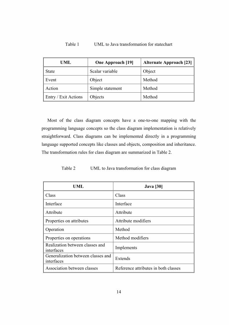
14
Table 1 UML to Java transformation for statechart
UML One Approach [19] Alternate Approach [23]
State Scalar variable Object
Event Object Method
Action Simple statement Method
Entry / Exit Actions Objects Method
Most of the class diagram concepts have a one-to-one mapping with the
programming language concepts so the class diagram implementation is relatively
straightforward. Class diagrams can be implemented directly in a programming
language supported concepts like classes and objects, composition and inheritance.
The transformation rules for class diagram are summarized in Table 2.
Table 2 UML to Java transformation for class diagram
UML Java [30]
Class Class
Interface Interface
Attribute Attribute
Properties on attributes Attribute modifiers
Operation Method
Properties on operations Method modifiers Realization between classes and interfaces Implements
Generalization between classes and interfaces Extends
Association between classes Reference attributes in both classes
15
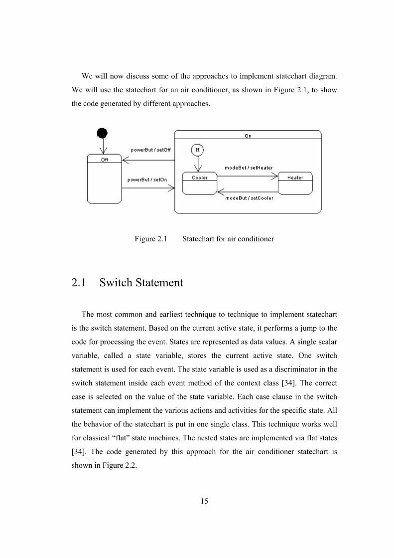
We will now discuss some of the approaches to implement statechart diagram.
We will use the statechart for an air conditioner, as shown in Figure 2.1, to show
the code generated by different approaches.
Figure 2.1 Statechart for air conditioner
2.1 Switch Statement
The most common and earliest technique to technique to implement statechart
is the switch statement. Based on the current active state, it performs a jump to the
code for processing the event. States are represented as data values. A single scalar
variable, called a state variable, stores the current active state. One switch
statement is used for each event. The state variable is used as a discriminator in the
switch statement inside each event method of the context class [34]. The correct
case is selected on the value of the state variable. Each case clause in the switch
statement can implement the various actions and activities for the specific state. All
the behavior of the statechart is put in one single class. This technique works well
for classical “flat” state machines. The nested states are implemented via flat states
[34]. The code generated by this approach for the air conditioner statechart is
shown in Figure 2.2.
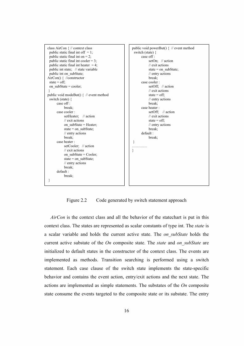
16
Figure 2.2 Code generated by switch statement approach
AirCon is the context class and all the behavior of the statechart is put in this
context class. The states are represented as scalar constants of type int. The state is
a scalar variable and holds the current active state. The on_subState holds the
current active substate of the On composite state. The state and on_subState are
initialized to default states in the constructor of the context class. The events are
implemented as methods. Transition searching is performed using a switch
statement. Each case clause of the switch state implements the state-specific
behavior and contains the event action, entry/exit actions and the next state. The
actions are implemented as simple statements. The substates of the On composite
state consume the events targeted to the composite state or its substate. The entry
class AirCon { // context class public static final int off = 1; public static final int on = 2; public static final int cooler = 3; public static final int heater = 4; public int state; // state variable public int on_subState; AirCon() { //constructor state = off; on_subState = cooler; } public void modeBut() { // event method switch (state) { case off : break; case cooler : setHeater; // action // exit actions on_subState = Heater; state = on_subState; // entry actions break; case heater : setCooler; // action // exit actions on_subState = Cooler; state = on_subState; // entry actions break; default : break; }
public void powerBut() { // event method switch (state) { case off : setOn; // action // exit actions state = on_subState; // entry actions break; case cooler : setOff; // action // exit actions state = off; // entry actions break; case heater : setOff; // action // exit actions state = off; // entry actions break; default : break; } ………… }

17
and exit actions of a state have to be duplicated in every event method. In the
powerBut event method, the code is duplicated for the cooler state and the heater
state, as one of these states will be active when the composite state is active.
Switch statement provides a simple and straightforward implementation of the
statechart concepts. The structure of the statechart is hard coded into a single class.
There is a lot of code duplication and reuse of code is very difficult. Manual
coding of entry/exit actions and event actions is, however, cumbersome, mainly
because code pertaining to one state becomes distributed and repeated in many
places. This makes it difficult to modify and maintain when the topology of state
machine changes. It does not provide explicit means for reflecting the transition
structure, state hierarchy and entry/exit actions associated to states. Implementing
and maintaining the code generated by following this approach is error-prone and
labor intensive, but usable in automatic code generators where the code
maintenance is substituted by forward engineering. I-Logix’s Rhapsody [19]
follows an approach similar to this approach to implement UML statechart diagram.
2.2 Helper Object
In [23], the concept of a helper object is introduced, which is an object-oriented
replacement of the switch statement. It puts each case clause in a separate object.
The helper object handles all the state-specific requests forwarded to it by the
multi-state domain object (context). The behavior of the multi-state domain object
is split into context and a state. The context responds differently to each external
message depending upon its current state. Helper object puts the behavior
associated with a particular state into one object. The helper object encapsulates all
the state-specific behavior of the context. The helper object represents the current
state of the context object and implements the behavior specific to the current state.
18
The context object delegates all external messages to its helper object and the
helper objects responds to the message on behalf of the domain object. The state
object is created temporarily. When the state of the domain object changes, a new
helper object, implementing the behavior specific to the new state, replaces the old
one. The source state is responsible for the change of state of the helper object.
Events become methods in the context class. The context has a method for each
event of the statechart. Instead of implementing the event method, the context
object delegates all requests (events) for processing to the current state object. The
transition searching is performed using polymorphism. Separating behavior into
disparate objects makes sense when the separation takes advantage of
polymorphism. Polymorphism allows two objects to be treated identically, even
though the objects implement these methods in quite different ways. The transition
to a different state means replacement of the current state object by another state
object. The actions become methods in the context class.
An abstract state class is used for defining the interface for encapsulating the
behavior associated with a particular state of the context. The abstract state class
declares an interface common to all state classes and its purpose is to make all the
state classes able to accept every event of the statechart. The interface for internal
events and entry /exit actions are also declared in this abstract class.
The state object contains state-specific attributes and implementation for state-
dependent behavior. Each state in the statechart diagram becomes a class and is
derived from the abstract state class. All the behavior associated with a particular
state is put in this state class. Introducing separate objects for different states
makes the transitions more explicit.
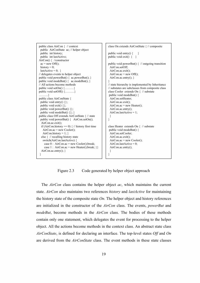
The code generated by this approach for the air conditioner statechart is shown
in Figure 2.3.
19
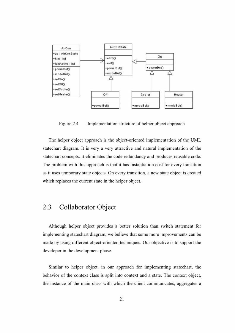
Figure 2.3 Code generated by helper object approach
The AirCon class contains the helper object ac, which maintains the current
state. AirCon also maintains two references history and lastActive for maintaining
the history state of the composite state On. The helper object and history references
are initialized in the constructor of the AirCon class. The events, powerBut and
modeBut, become methods in the AirCon class. The bodies of these methods
contain only one statement, which delegates the event for processing to the helper
object. All the actions become methods in the context class. An abstract state class
AirConState, is defined for declaring an interface. The top-level states Off and On
are derived from the AirConState class. The event methods in these state classes
public class AirCon { // context public AirConState ac; // helper object public int history; public int lastActive; AirCon() { //constructor ac = new Off(); history = 0; lastActive = 0; } // delegates events to helper object public void powerBut() { ac.powerBut(); } public void modeBut() { ac.modeBut(); } // All actions become methods public void setOn() {………} public void setOff() {………} ………} public class AirConState { public void entry() {}; public void exit() {}; public void powerBut() {}; public void modeBut() {}; } public class Off extends AirConState { // state public void powerBut() { AirCon.setOn(); AirCon.ac.exit(); if (AirCon.history == 0) { // history first time AirCon.ac = new Cooler(); AirCon.history = 1; } else { // recalling history state switch(AirCon.lastActive) { case 0 : AirCon.ac = new Cooler();break; case 1 : AirCon.ac = new Heater();break; }} AirCon.ac.entry(); } }
class On extends AirConState { // composite public void entry() { } public void exit() { } public void powerBut() { // outgoing transition AirCon.setOff; AirCon.ac.exit(); AirCon.ac = new Off(); AirCon.ac.entry(); } } // state hierarchy is implemented by Inheritance // substates are subclasses from composite class class Cooler extends On { // substate public void modeBut() { AirCon.setHeater; AirCon.ac.exit(); AirCon.ac = new Heater(); AirCon.ac.entry(); AirCon.lastActive = 1; } } class Heater extends On { // substate public void modeBut() { AirCon.setCooler; AirCon.ac.exit(); AirCon.ac = new Cooler(); AirCon.lastActive = 0; AirCon.ac.entry(); } }
20
implement the behavior. The state objects define the transitions. On transition, first
of all the event action is executed followed by the exit actions of the current state.
The new object for the next state is created and its reference is stored in the helper
object. Then the entry action of the new state is executed. The implementation of
history state is not encapsulated in the composite state On but rather it is
distributed among state objects and the domain object AirCon.
The state hierarchy is implemented by using inheritance. The statechart
structure becomes the class hierarchy. The substates, Cooler and Heater, become
subclasses of the superstate class On. The super class implements the behavior
specific to the super state and the subclasses implement the behavior specific to the
substates. The reference lastActive, which represents the most recent active
substate, is updated each time the substate is exited. The super class never becomes
active, rather the current active substate handles the transitions for the super state
class as they inherit all the methods of the superstate class. The problem with this
approach is that it generates code only for the domain class with which the
statechart is attached. OCode [24, 25] used a similar approach to implement Object
Modeling Technique (OMT) [6, 31, 32, 33] dynamic model.
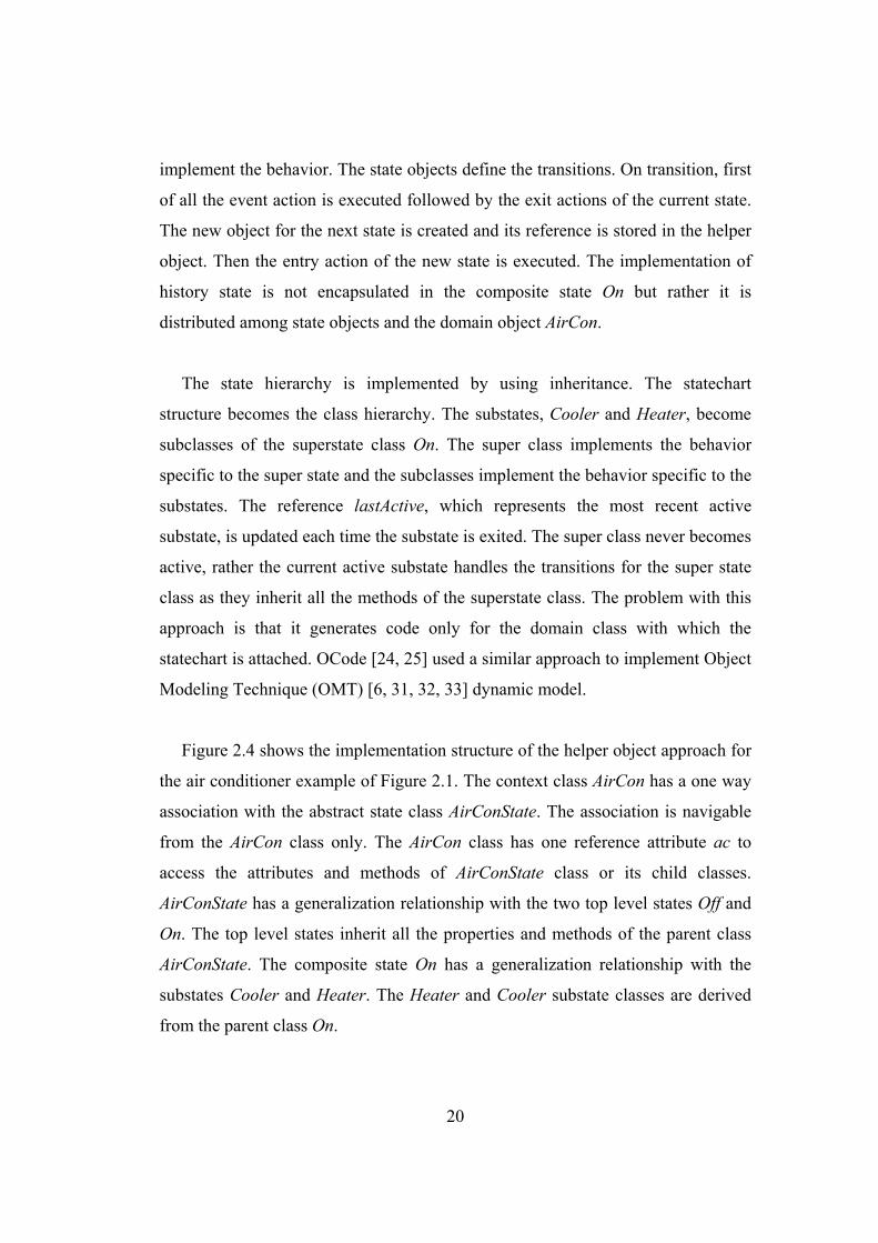
Figure 2.4 shows the implementation structure of the helper object approach for
the air conditioner example of Figure 2.1. The context class AirCon has a one way
association with the abstract state class AirConState. The association is navigable
from the AirCon class only. The AirCon class has one reference attribute ac to
access the attributes and methods of AirConState class or its child classes.
AirConState has a generalization relationship with the two top level states Off and
On. The top level states inherit all the properties and methods of the parent class
AirConState. The composite state On has a generalization relationship with the
substates Cooler and Heater. The Heater and Cooler substate classes are derived
from the parent class On.
21
Figure 2.4 Implementation structure of helper object approach
The helper object approach is the object-oriented implementation of the UML
statechart diagram. It is very a very attractive and natural implementation of the
statechart concepts. It eliminates the code redundancy and produces reusable code.
The problem with this approach is that it has instantiation cost for every transition
as it uses temporary state objects. On every transition, a new state object is created
which replaces the current state in the helper object.
2.3 Collaborator Object
Although helper object provides a better solution than switch statement for
implementing statechart diagram, we believe that some more improvements can be
made by using different object-oriented techniques. Our objective is to support the
developer in the development phase.
Similar to helper object, in our approach for implementing statechart, the
behavior of the context class is split into context and a state. The context object,
the instance of the main class with which the client communicates, aggregates a
22
collaborator object that is used to represent the behavior in one of its states. The
context object defines the interface to clients. The collaborator object encapsulates
all the state-specific behavior of the context. The context object maintains a
collaborator object that points to an instance of current active state object. We have
used more persistent and permanent objects. The context object maintains
references of all the state objects and they are created once in the constructor of the
context object. The instantiation cost is paid only once. On transition, the context
class is responsible for setting the new state by changing the state reference in the
collaborator object. The states are represented as objects and implement state-
specific behavior.
The events are represented as methods. The context object delegates all events
to the collaborator object for processing. State transitions are accomplished by
changing the collaborator object with the reference of next state. No new object is
created. Transition searching is performed using polymorphism. The actions in the
transitions of a state machine perform operations on data in the system. We
consider action as a message that performs operations on the data of the context
object so each action of the statechart becomes a method in the context class.
An abstract state class is defined for defining the interface to state classes. The
name of the abstract state class is derived from the context class name and State is
added to it. Each state in the statechart diagram becomes a class and is derived
from the abstract state class. The name of the state becomes the name of the class.
All the behavior associated with a particular state is put in this state class. The state
object contains state-specific attributes and implementation for state-dependent
behavior. Each transition from a state becomes a method in the corresponding state
class in order to provide a uniform and convenient way of invoking some services
on the context object. Internal transitions and entry/exit actions are owned by their
containing states so they are implemented as methods in the corresponding state
class. If-then statement is used to check whether the guard condition is satisfied.
23
All the state-specific code resides in one class. The logic that determines the state
transitions is partitioned between the state classes. Methods in the state do not need
conditional analysis and have no concern for processing in other states.
Encapsulating each state transition in a class elevates the idea of an execution state
to full object status. Introducing separate objects for different states makes the
transitions more explicit. That imposes structure on the code and makes its intent
clear.
The composite states containing hierarchical or concurrent substates are
implemented by using the concept of object composition and delegation. Object
composition is defined dynamically at runtime through objects acquiring
references to other objects. New functionality is obtained by composing objects to
get more complex functionality. Object composition keeps each class encapsulated
and there are fewer dependencies. Any object can be replaced at runtime by
another as long as it has the same type. Delegation is a way of making object
composition powerful for reuse. The main advantage of delegation is that it makes
it easy to compose behavior at runtime and to change the way objects are
composed. The behavior of the composite state is split into composite state and its
substate. The composite state aggregates a collaborator object that is used to
represent the behavior in one of its substates. The composite state object maintains
a collaborator object that points to an instance of current active state substate.
Events that have its substate as target are delegated to collaborator object for
processing. The composite state class is responsible for changing the next substate
in its collaborator object. Substates implements behavior specific to substates and
are derived from a common interface class (each method in this interface
corresponds to an event) that declares handler functions for the events received by
the composite state class. The code generated by our approach for the air
conditioner statechart is shown in Figure 2.5.
24
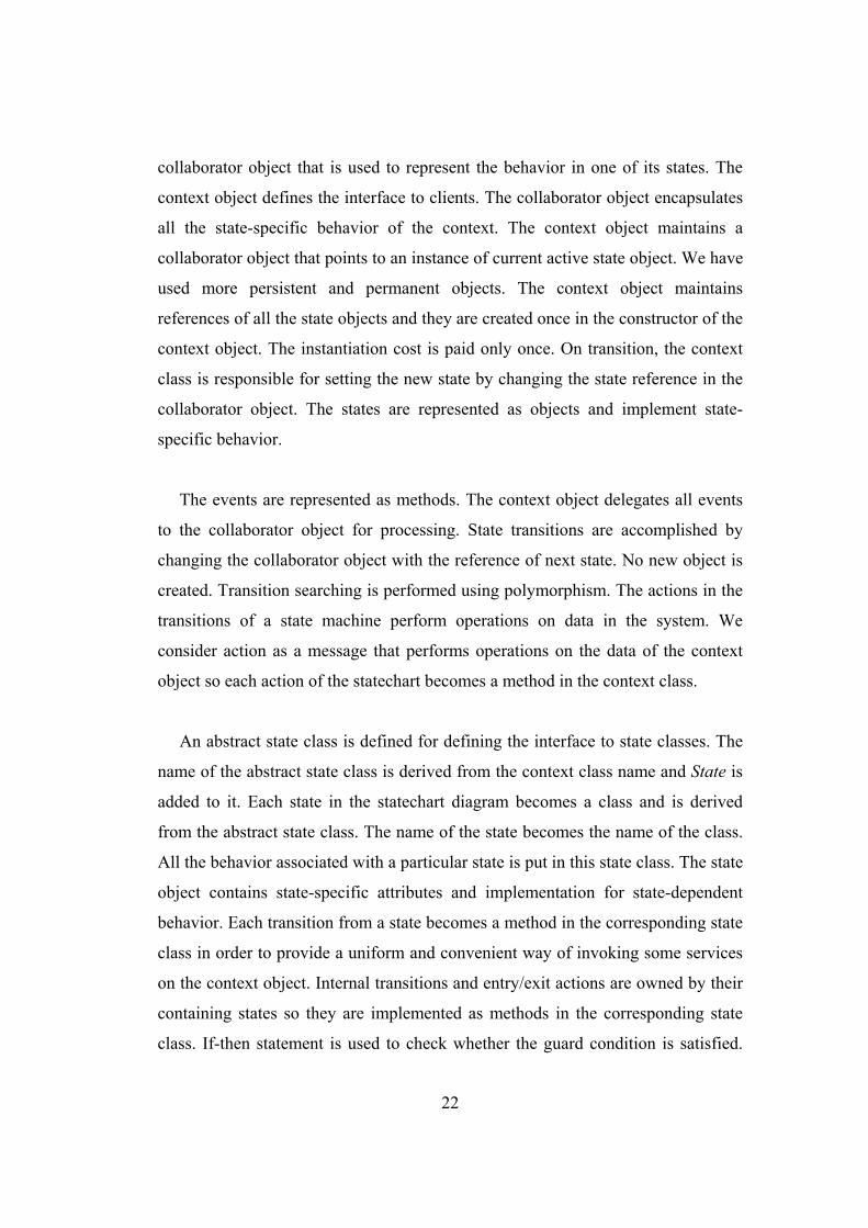
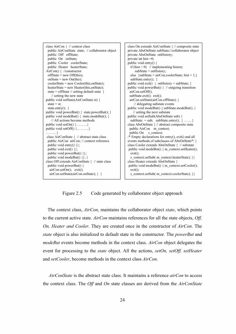
Figure 2.5 Code generated by collaborator object approach
The context class, AirCon, maintains the collaborator object state, which points
to the current active state. AirCon maintains references for all the state objects, Off,
On, Heater and Cooler. They are created once in the constructor of AirCon. The
state object is also initialized to default state in the constructor. The powerBut and
modeBut events become methods in the context class. AirCon object delegates the
event for processing to the state object. All the actions, setOn, setOff, setHeater
and setCooler, become methods in the context class AirCon.
AirConState is the abstract state class. It maintains a reference airCon to access
the context class. The Off and On state classes are derived from the AirConState
class AirCon { // context class public AirConState state; // collaborator object public Off offState; public On onState; public Cooler coolerState; public Heater heaterState; AirCon() { //constructor offState = new Off(this); onState = new On(this); coolerState = new Cooler(this,onState); heaterState = new Heater(this,onState); state = offState // setting default state } // setting the new state public void setState(AirConState st) { state = st; state.entry(); } public void powerBut() { state.powerBut(); } public void modeBut() { state.modeBut(); } // All actions become methods public void setOn() {………} public void setOff() {……….} ………} class AirConState { // abstract state class public AirCon airCon; // context reference public void entry() {}; public void exit() {}; public void powerBut() {}; public void modeBut() {}; } class Off extends AirConState { // state class public void powerBut() { airCon.setOn(); exit(); airCon.setState(airCon.onState); } }
class On extends AirConState { // composite stateprivate AbsOnState subState;//collaborator objectprivate AbsOnState onHistory; private int hist =0; public void entry() { if (hist > 0) // implementing history subState = onHistory; else {subState = airCon.coolerState; hist = 1;} subState.entry(); } public void exit() { onHistory = subState; } public void powerBut() { // outgoing transition airCon.setOff(); subState.exit(); exit(); airCon.setState(airCon.offState); } // delegating substate events public void modeBut() { subState.modeBut(); } // setting the next substate public void setSub(AbsOnState sub) { subState = sub; subState.entry(); } …….} class AbsOnState { // abstract composite state public AirCon m_context; public On s_context; /* Empty declarations for entry(), exit() and all events methods of subclasses of AbsOnState*/ } class Cooler extends AbsOnState { // substate public void modeBut() { m_context.setHeater(); exit(); s_context.setSub( m_context.heaterState); }} class Heater extends AbsOnState { public void modeBut() { m_context.setCooler(); exit(); s_context.setSub( m_context.coolerState); }}
25
class. The state classes implements the state-specific behavior. In our approach, the
context object defines the transitions. On handling the transitions, the current state
object first executes the associated action with the transition followed by the exit
action of the current state and then calls the setState() method of the context object
AirCon to set the new state. In the setState() method, no new object is created, the
state object is simply updated with the reference of the new state. The entry action
of the new state is also executed in the setState() method. The state object is
responsible for specifying the successor state. Decentralizing the transition logic in
this way makes it easy to modify or extend the logic by defining new state
subclasses.
The state hierarchy is implemented by object composition and delegation. The
composite state object, On, maintains two references with private visibility,
collaborator object Substate and onHistory, for maintaining the current active
substate and the history state. The onHistory reference is used to set the active
substate in the entry() method of the composite state On, whenever the composite
becomes active. The onHistory is adjusted to the last active substate in the exit()
method of the composite state. In this way the implementation of history state is
encapsulated in the composite state. The composite state remains in control all the
time. If the target of the incoming transition is a substate, then it will delegate the
event to the collaborator object. The composite state On, is responsible for defining
the transitions in the setSub() method. The substate specifies the successor substate.
An abstract composite class AbsOnState is defined which contains empty
declarations for entry/exit actions and all the event methods, which are specific to
the substates of the On composite state. The substates Cooler and Heater are
derived from abstract composite state class AbsOnState. The substates implement
the event methods targeted to the substates.
26
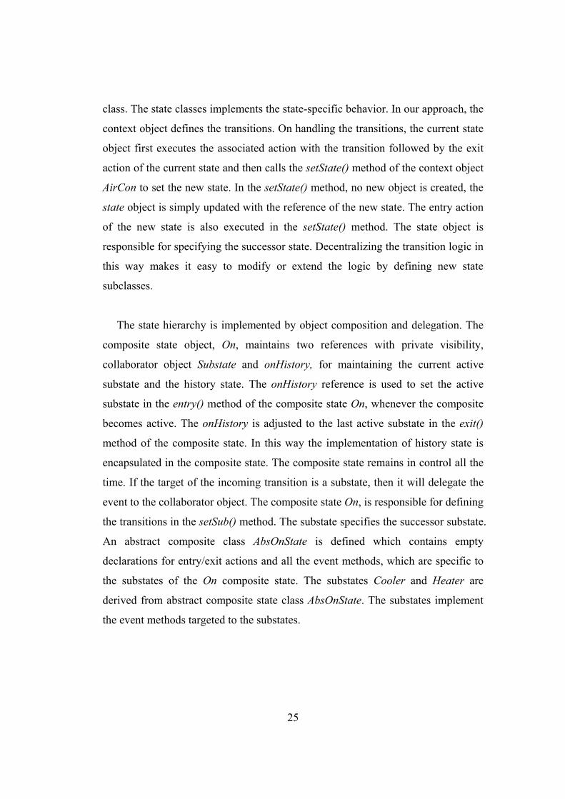
Figure 2.6 Implementation structure of collaborator object approach
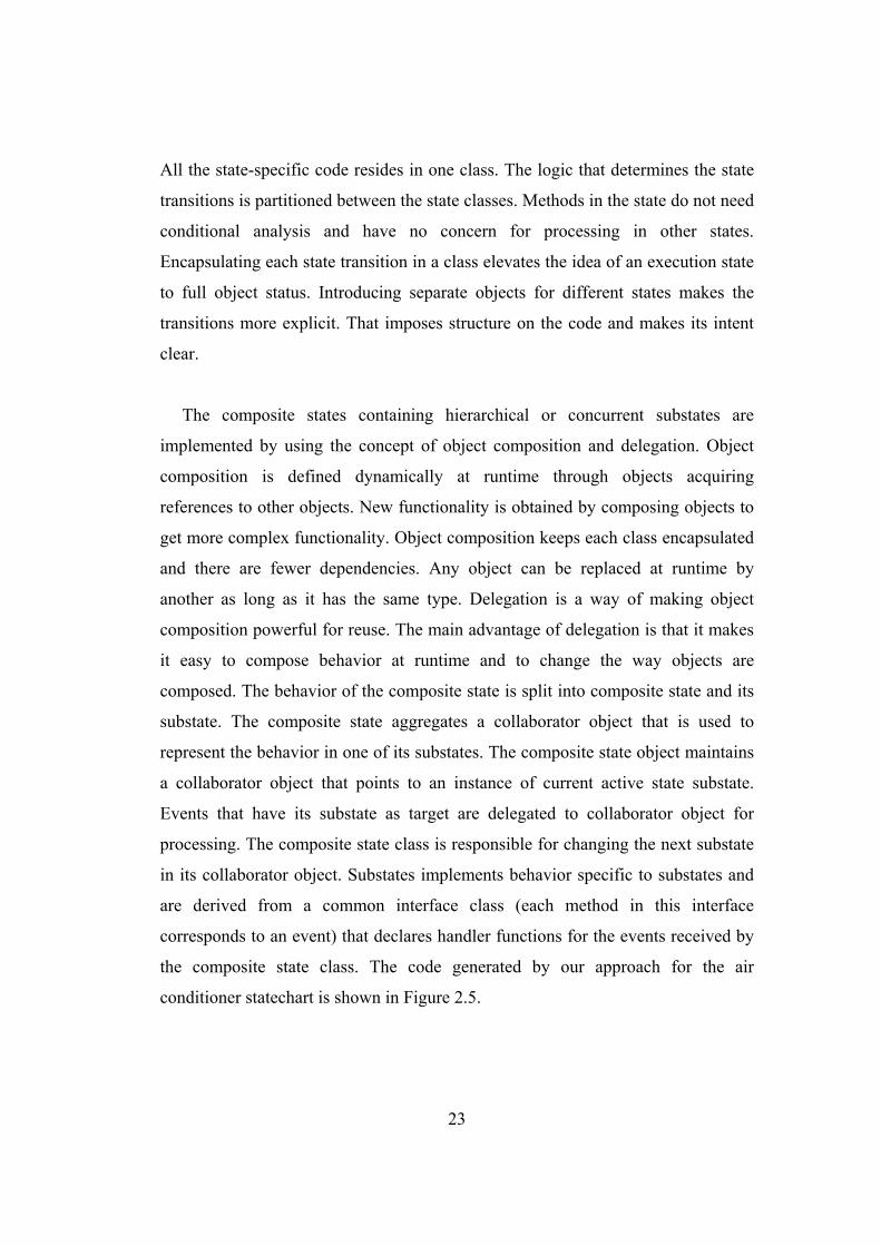
Figure 2.6 shows the implementation structure of our approach for the air
conditioner statechart as shown in Figure 2.1. The context class AirCon has a
bidirectional association with the abstract state class AirConState. The object of
one class can navigate the object of the other class. The AirCon class has the
reference state object to access the event methods of the state object. The
AirConState contains a reference airCon to the context object. The state objects,
Off and On, inherit this reference to access the methods of the AirCon context
object. The AirConState has a generalization relationship with the two top level
state Off and On. The Off and On states become the child classes of the parent class
AirConState and inherit all the attributes and methods of the parent class. The
abstract composite state class AbsOnState has associations with AirCon and On. It
contains two references, m_context and s_context, one to access the main context
class AirCon for executing the event actions and the other one to access the super
context class On, for changing the next substate. The association between context
AirCon class and the AbsOnState is in one direction and is navigable from the
27
AirConState class only. The association between AbsOnState and On class is
bidirectional and both classes contain a reference attribute to access the objects of
the other class. The AbsOnState has a generalization relationship with the substates
Cooler and Heater. The substates classes are derived from the parent class
AbsOnState.
The collaborator object approach for implementing statechart diagram provides
better encapsulation and produces more reusable code.
28
Chapter 3
Combining Class Diagram And Statechart Diagrams A system consists of multiple statechart diagrams, each of which shows the
behavior of a particular class of objects contained in the class diagram of the
system. In this chapter, we demonstrate our code generation approach from the
UML class and statechart diagrams.
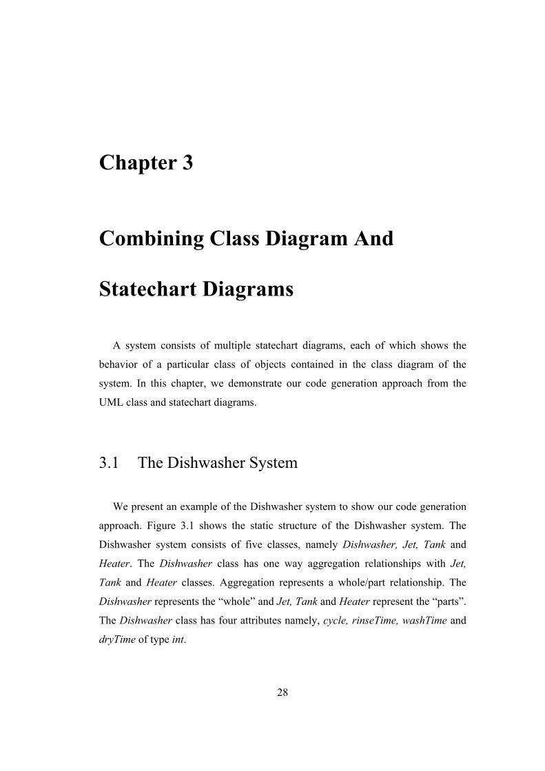
3.1 The Dishwasher System
We present an example of the Dishwasher system to show our code generation
approach. Figure 3.1 shows the static structure of the Dishwasher system. The
Dishwasher system consists of five classes, namely Dishwasher, Jet, Tank and
Heater. The Dishwasher class has one way aggregation relationships with Jet,
Tank and Heater classes. Aggregation represents a whole/part relationship. The
Dishwasher represents the “whole” and Jet, Tank and Heater represent the “parts”.
The Dishwasher class has four attributes namely, cycle, rinseTime, washTime and
dryTime of type int.
29
Figure 3.1 Class diagram for the dishwasher system
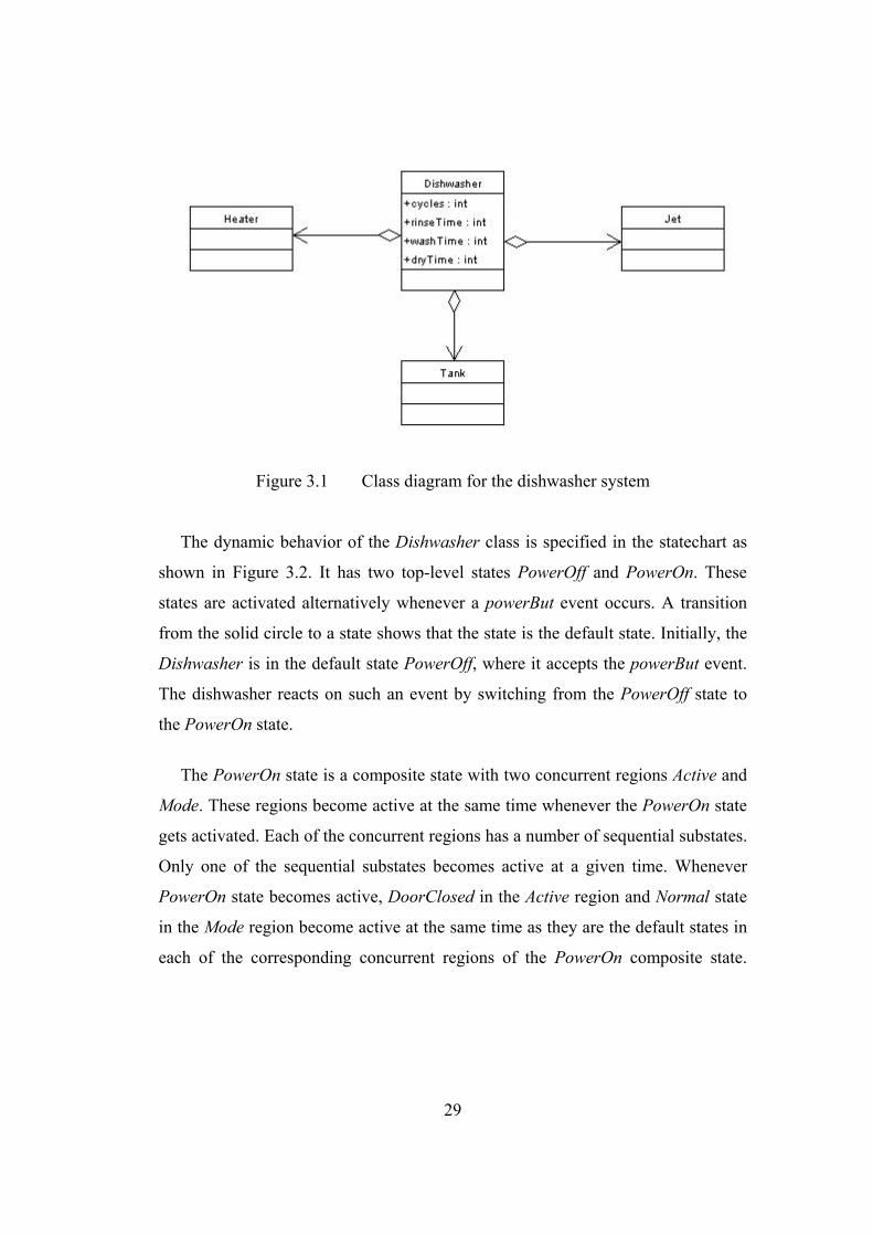
The dynamic behavior of the Dishwasher class is specified in the statechart as
shown in Figure 3.2. It has two top-level states PowerOff and PowerOn. These
states are activated alternatively whenever a powerBut event occurs. A transition
from the solid circle to a state shows that the state is the default state. Initially, the
Dishwasher is in the default state PowerOff, where it accepts the powerBut event.
The dishwasher reacts on such an event by switching from the PowerOff state to
the PowerOn state.
The PowerOn state is a composite state with two concurrent regions Active and
Mode. These regions become active at the same time whenever the PowerOn state
gets activated. Each of the concurrent regions has a number of sequential substates.
Only one of the sequential substates becomes active at a given time. Whenever
PowerOn state becomes active, DoorClosed in the Active region and Normal state
in the Mode region become active at the same time as they are the default states in
each of the corresponding concurrent regions of the PowerOn composite state.
30
Figure 3.2 Statechart of Dishwasher class
While in PowerOn state, on close or open event the Dishwasher switches to the
next sequential state in the Active region. The DoorClosed substate is a composite
hierarchical state containing Stop, Filling, Rinsing, Washing, Draining and Drying
sequential substates. When the DoorClosed state is active, exactly one of its

31
sequential substates is also active at the same time. On open event the dishwasher
switches to DoorOpen state in the Active region. On close event, it switches into
the history state of the DoorClosed state and recalls the last active substate of the
DoorClosed state. A statechart describes the dynamic aspects of an object whose
current behavior depends on its past. A statechart in effect specifies the legal
ordering of states an object goes through its lifetime. History state allows a
composite state that contains sequential substates to remember the last substates
that was active in it prior to the transition from the composite state. Similarly, on
intMode, normMode or quickMode event, the Dishwasher switches to the next
sequential substate in the Mode region.
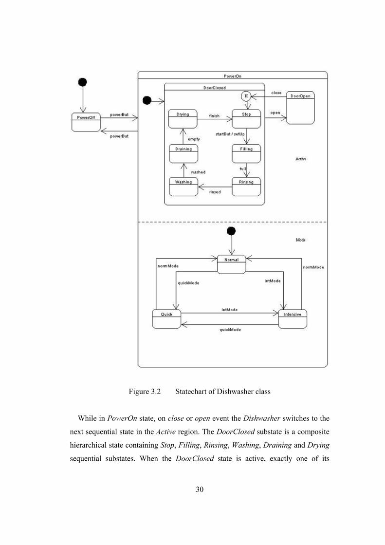
The dynamic behavior of the Tank class is specified in the statechart as shown
in Figure 3.3. It has four top-level states Empty, Fill, Full and Drain. These states
are activated alternatively whenever a tankFill, tankFull, tankDrain, or tankEmpty
event occurs. Initially, the Tank is in the default state Empty, where it accepts the
tankFill event. The Tank reacts on such an event by switching from the Empty state
to the Fill state.
Figure 3.3 Statechart of Tank class
32
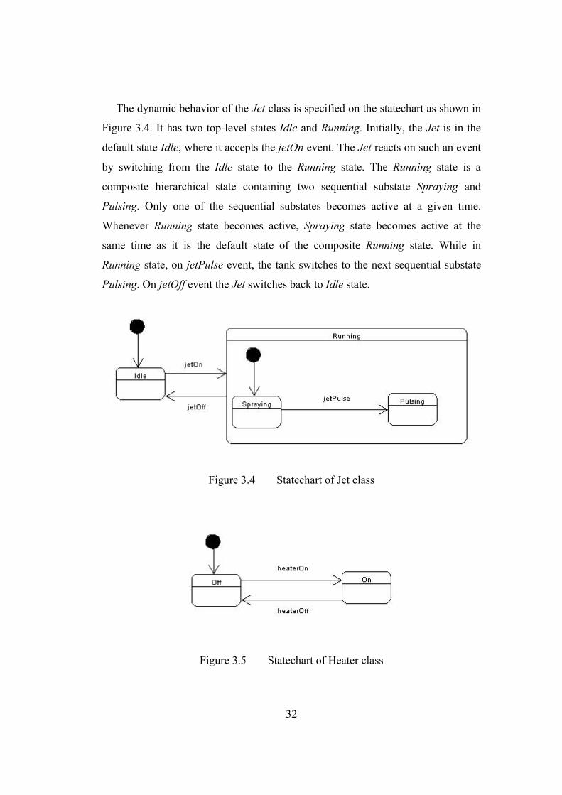
The dynamic behavior of the Jet class is specified on the statechart as shown in
Figure 3.4. It has two top-level states Idle and Running. Initially, the Jet is in the
default state Idle, where it accepts the jetOn event. The Jet reacts on such an event
by switching from the Idle state to the Running state. The Running state is a
composite hierarchical state containing two sequential substate Spraying and
Pulsing. Only one of the sequential substates becomes active at a given time.
Whenever Running state becomes active, Spraying state becomes active at the
same time as it is the default state of the composite Running state. While in
Running state, on jetPulse event, the tank switches to the next sequential substate
Pulsing. On jetOff event the Jet switches back to Idle state.
Figure 3.4 Statechart of Jet class
Figure 3.5 Statechart of Heater class
33
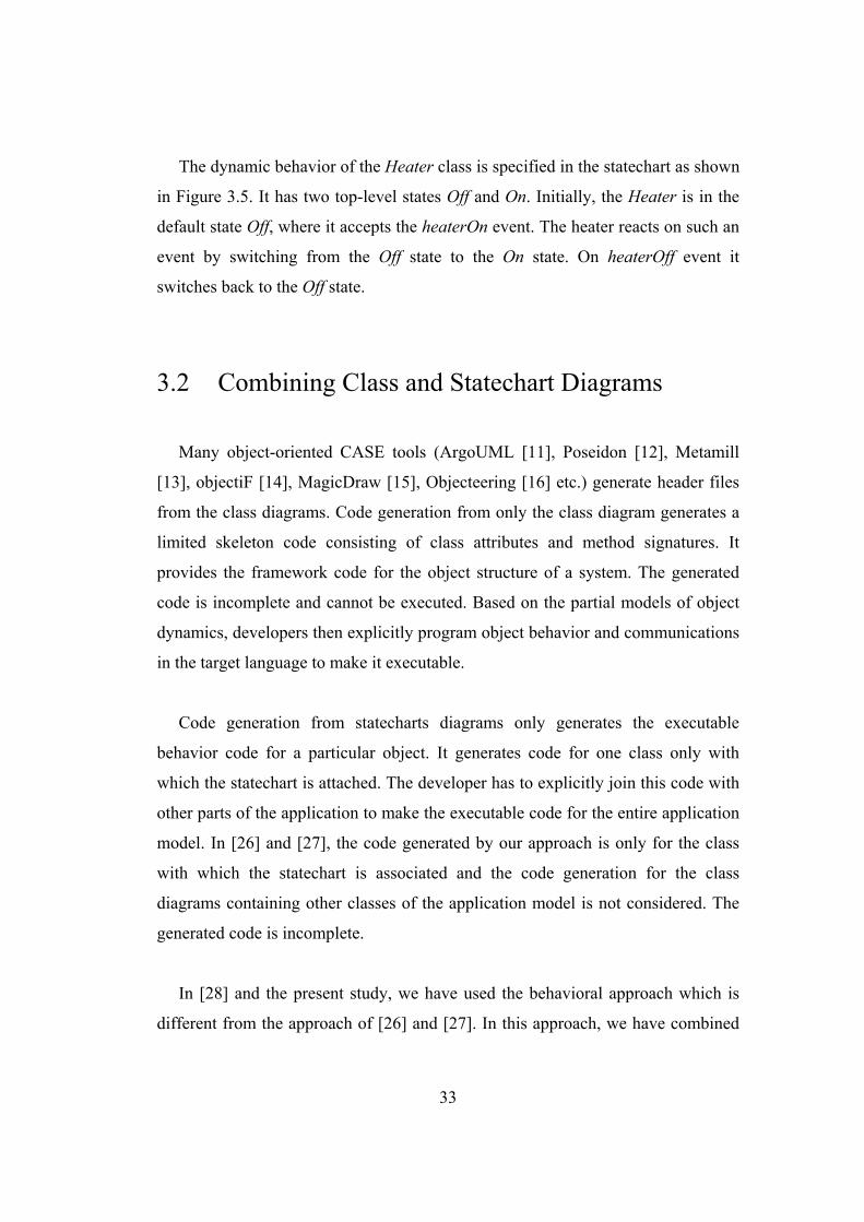
The dynamic behavior of the Heater class is specified in the statechart as shown
in Figure 3.5. It has two top-level states Off and On. Initially, the Heater is in the
default state Off, where it accepts the heaterOn event. The heater reacts on such an
event by switching from the Off state to the On state. On heaterOff event it
switches back to the Off state.
3.2 Combining Class and Statechart Diagrams
Many object-oriented CASE tools (ArgoUML [11], Poseidon [12], Metamill
[13], objectiF [14], MagicDraw [15], Objecteering [16] etc.) generate header files
from the class diagrams. Code generation from only the class diagram generates a
limited skeleton code consisting of class attributes and method signatures. It
provides the framework code for the object structure of a system. The generated
code is incomplete and cannot be executed. Based on the partial models of object
dynamics, developers then explicitly program object behavior and communications
in the target language to make it executable.
Code generation from statecharts diagrams only generates the executable
behavior code for a particular object. It generates code for one class only with
which the statechart is attached. The developer has to explicitly join this code with
other parts of the application to make the executable code for the entire application
model. In [26] and [27], the code generated by our approach is only for the class
with which the statechart is associated and the code generation for the class
diagrams containing other classes of the application model is not considered. The
generated code is incomplete.
In [28] and the present study, we have used the behavioral approach which is
different from the approach of [26] and [27]. In this approach, we have combined
34
class diagrams together with the statechart diagrams for complete code generation
of the entire application model. Combining class and statechart diagrams broadens
the application field and covers a wider area by including static as well as
behavioral information. We can now handle more complex problems containing
more than one statechart and more complex statechart diagrams. Our approach
generates code for the structural model as well as the behavioral code.
In our approach, an application class is generated in a separate file. All
instances of classes in the class diagram are defined in the application class. The
object instances are created once in the constructor of the application class. It also
contains the main() method, which serves as an entry point for the application. The
initialization code is also generated in the main() method. Separate files, containing
the implementation code for each class appearing in the class diagram, are
generated. If there is no statechart attached with the class then the generated code
contains only the class attributes, attributes for association with other classes and
the methods signatures. The behavioral aspects of a class are specified in the
attached statechart. If a class has an associated statechart then the generated code
contains the behavior implementation for the context class in addition to the class
attributes, association attributes and method signatures. In the same file the code
for the state classes of the statechart is also generated according to the collaborator
object approach, as described in chapter 2. We have put the structural and
behavioral code for a class in one Java file. The generated code is executable and
contains all the information given in the application model.

35
Figure 3.6 Overview of the JCode system
The JCode system is developed, which automatically generates the executable
Java [30] code from the specifications of the UML class and statechart diagrams
using our code generation approach. Figure 3.6 shows the overview of the JCode
system. The input to the system is the class and statechart diagrams specifications
in Design Schema List Language (DSL) [29]. DSL is a specification language to
represent class and statechart diagram in an understandable text format and to
facilitate data exchanges among tools and members of the group. The output of the
system is the executable Java [30] code.
We will demonstrate our code generation approach by generating code for the
dishwasher system as shown in Figure 3.1. The JCode system works in three major
modules, namely class diagram module, statechart module and the code generation
module. Following is the brief description of each of the modules.
Class Diagram
Module
Statechart Module
Class and State Tables Java
code Class Diagram
DSL file
Code Generation
Statechart DSL file name State Tables
Statechart DSL file
36
3.2.1 Class Diagram Module
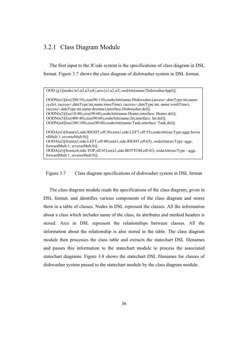
The first input to the JCode system is the specifications of class diagram in DSL
format. Figure 3.7 shows the class diagram of dishwasher system in DSL format.
Figure 3.7 Class diagram specifications of dishwasher system in DSL format
The class diagram module reads the specifications of the class diagram, given in
DSL format, and identifies various components of the class diagram and stores
them in a table of classes. Nodes in DSL represent the classes. All the information
about a class which includes name of the class, its attributes and method headers is
stored. Arcs in DSL represent the relationships between classes. All the
information about the relationship is also stored in the table. The class diagram
module then processes the class table and extracts the statechart DSL filenames
and passes this information to the statechart module to process the associated
statechart diagrams. Figure 3.8 shows the statechart DSL filenames for classes of
dishwasher system passed to the statechart module by the class diagram module.
OOD (g1)[nodes{n1,n2,n3,n4},arcs{a1,a2,a3},oodAttr(name:DishwasherAppl)]; OODN(n1)[loc(200:10),size(90:110),oodnAttr(name:Dishwasher,(access+,dateType:int,name: cycle), (access+,dateType:int,name:rinseTime), (access+,dateType:int, name:washTime), (access+,dateType:int,name:drytime),interface:Dishwasher.dsl)]; OODN(n2)[loc(10:40),size(90:60),oodnAttr(name:Heater,interface: Heater.dsl)]; OODN(n3)[loc(400:40),size(90:60),oodnAttr(name:Jet,interface: Jet.dsl)]; OODN(n4)[loc(200:180),size(90:60),oodnAttr(name:Tank,interface: Tank.dsl)]; OODA(a1)[from(n2,side:RIGHT,off:30),to(n1,side:LEFT,off:55),oodaAttr(arcType:aggr,forwardMult:1, reverseMult:0)]; OODA(a2)[from(n3,side:LEFT,off:40),to(n1,side:RIGHT,off:65), oodaAttr(arcType: aggr, forwardMult:1, reverseMult:0)]; OODA(a3)[from(n4,side:TOP,off:45),to(n1,side:BOTTOM,off:45), oodaAttr(arcType : aggr, forwardMult:1, reverseMult:0)];
37
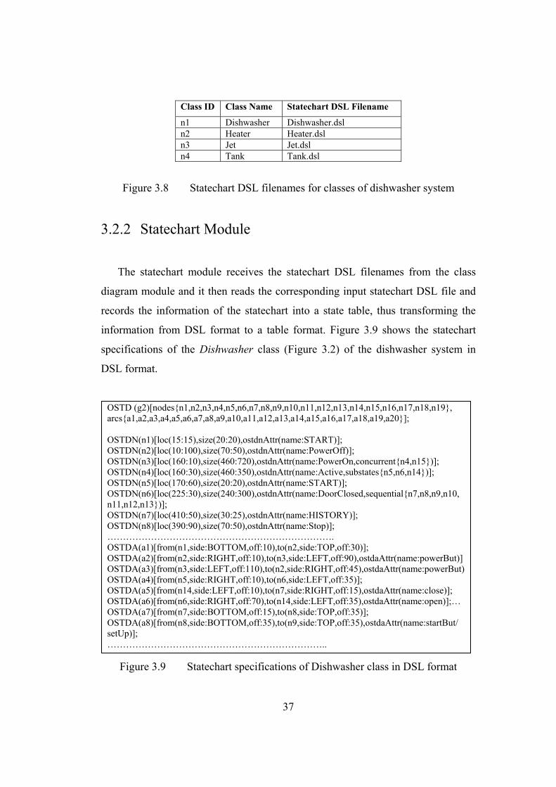
Class ID Class Name Statechart DSL Filename
n1 Dishwasher Dishwasher.dsl n2 Heater Heater.dsl n3 Jet Jet.dsl n4 Tank Tank.dsl
Figure 3.8 Statechart DSL filenames for classes of dishwasher system
3.2.2 Statechart Module
The statechart module receives the statechart DSL filenames from the class
diagram module and it then reads the corresponding input statechart DSL file and
records the information of the statechart into a state table, thus transforming the
information from DSL format to a table format. Figure 3.9 shows the statechart
specifications of the Dishwasher class (Figure 3.2) of the dishwasher system in
DSL format.
Figure 3.9 Statechart specifications of Dishwasher class in DSL format
OSTD (g2)[nodes{n1,n2,n3,n4,n5,n6,n7,n8,n9,n10,n11,n12,n13,n14,n15,n16,n17,n18,n19}, arcs{a1,a2,a3,a4,a5,a6,a7,a8,a9,a10,a11,a12,a13,a14,a15,a16,a17,a18,a19,a20}]; OSTDN(n1)[loc(15:15),size(20:20),ostdnAttr(name:START)]; OSTDN(n2)[loc(10:100),size(70:50),ostdnAttr(name:PowerOff)]; OSTDN(n3)[loc(160:10),size(460:720),ostdnAttr(name:PowerOn,concurrent{n4,n15})]; OSTDN(n4)[loc(160:30),size(460:350),ostdnAttr(name:Active,substates{n5,n6,n14})]; OSTDN(n5)[loc(170:60),size(20:20),ostdnAttr(name:START)]; OSTDN(n6)[loc(225:30),size(240:300),ostdnAttr(name:DoorClosed,sequential{n7,n8,n9,n10, n11,n12,n13})]; OSTDN(n7)[loc(410:50),size(30:25),ostdnAttr(name:HISTORY)]; OSTDN(n8)[loc(390:90),size(70:50),ostdnAttr(name:Stop)]; ………………………………………………………………. OSTDA(a1)[from(n1,side:BOTTOM,off:10),to(n2,side:TOP,off:30)]; OSTDA(a2)[from(n2,side:RIGHT,off:10),to(n3,side:LEFT,off:90),ostdaAttr(name:powerBut)]OSTDA(a3)[from(n3,side:LEFT,off:110),to(n2,side:RIGHT,off:45),ostdaAttr(name:powerBut)OSTDA(a4)[from(n5,side:RIGHT,off:10),to(n6,side:LEFT,off:35)]; OSTDA(a5)[from(n14,side:LEFT,off:10),to(n7,side:RIGHT,off:15),ostdaAttr(name:close)]; OSTDA(a6)[from(n6,side:RIGHT,off:70),to(n14,side:LEFT,off:35),ostdaAttr(name:open)];…OSTDA(a7)[from(n7,side:BOTTOM,off:15),to(n8,side:TOP,off:35)]; OSTDA(a8)[from(n8,side:BOTTOM,off:35),to(n9,side:TOP,off:35),ostdaAttr(name:startBut/ setUp)]; ……………………………………………………………..
38
Outgoing Transitions State
ID State Name *=default
Substates Substate Events ID Event Action Next
Staten2 Idle* a2 jetOn n3 n3 Running n5, n6 jetPulse a3 jetOff n2 n5 Spraying* a5 jetPulse n6 n6 Pulsing
Figure 3.10 Part of the updated state table for statechart of Jet class
Outgoing Transitions State
ID State Name * = default + = history
Substates Substate Events ID Event Action Next
State n2 PowerOff* a2 powerBut n3 n3 PowerOn n4, n15 open, close,
startBut, full, rinsed, washed, empty, finish intMode, quickMode, normMode
a3 powerBut n2
n4 Active n6, n14 n6 DoorClosed+ n8,n9,n10,
n11,n12,n13 startBut, full, rinsed, washed, empty, finish
a5 open n14
n8 Stop* a8 startBut setUp n9 n9 Filling a9 full n10 n10 Rinsing a10 rinsed n11 n11 Washing a11 washed n12 n12 Draining a12 empty n13 n13 Drying a13 finish n8 n14 DoorOpen a14 close n6 n15 Mode n17,n18,n19 intMode,
quickMode, normMode
a15 intMode n18 n17 Normal* a20 quickMode n19 a16 normMode n17 n18 Intensive a17 quickMode n19 a18 intMode n18 n19 Quick a19 normMode n17
Figure 3.11 Part of the updated state table for statechart of Dishwasher class
39
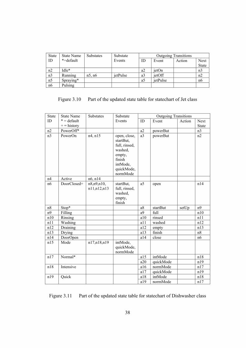
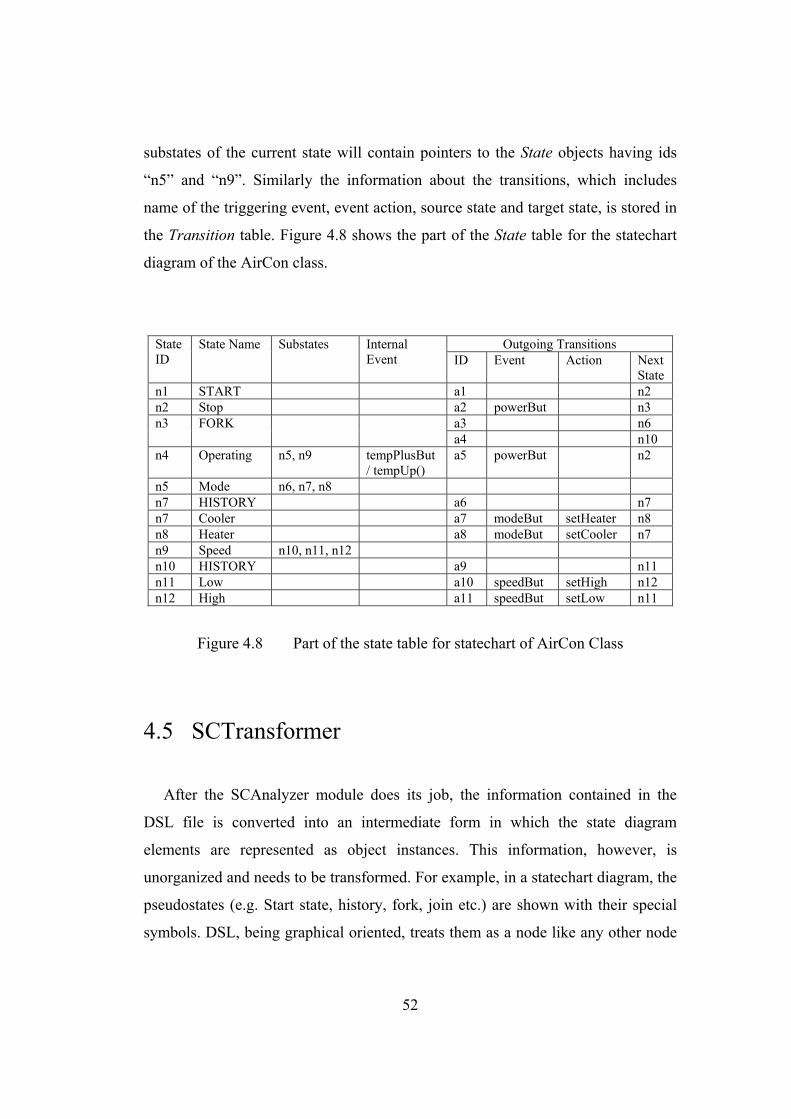
The statechart module then processes the state table and removes the
information of the pseudostates (Initial, History, Fork and Join etc.) from the state
table and updates the table accordingly. Figure 3.10.shows the updated state table
for the statechart diagram of the Jet class (Figure 3.4). Figure 3.11 shows the
updated state table for the statechart diagram of the Dishwasher class (Figure 3.2).
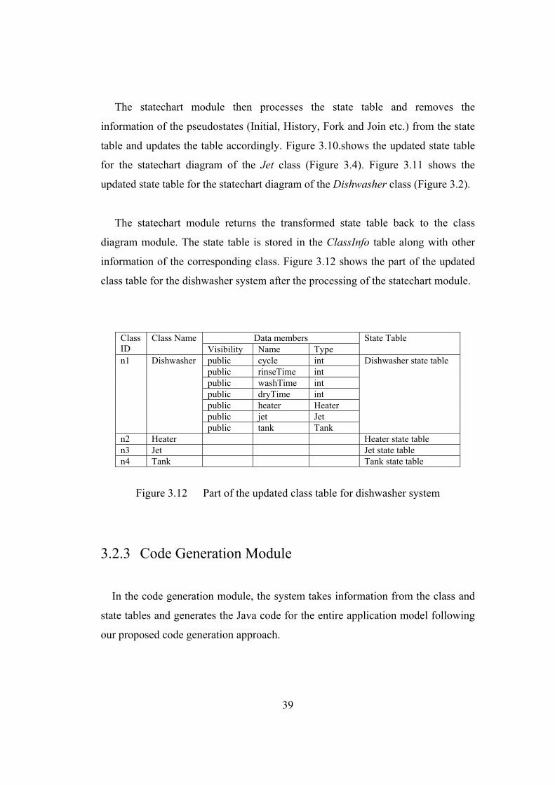
The statechart module returns the transformed state table back to the class
diagram module. The state table is stored in the ClassInfo table along with other
information of the corresponding class. Figure 3.12 shows the part of the updated
class table for the dishwasher system after the processing of the statechart module.
Data members Class
ID Class Name
Visibility Name Type State Table
public cycle int public rinseTime int public washTime int public dryTime int public heater Heater public jet Jet
n1 Dishwasher
public tank Tank
Dishwasher state table
n2 Heater Heater state table n3 Jet Jet state table n4 Tank Tank state table
Figure 3.12 Part of the updated class table for dishwasher system
3.2.3 Code Generation Module
In the code generation module, the system takes information from the class and
state tables and generates the Java code for the entire application model following
our proposed code generation approach.
40
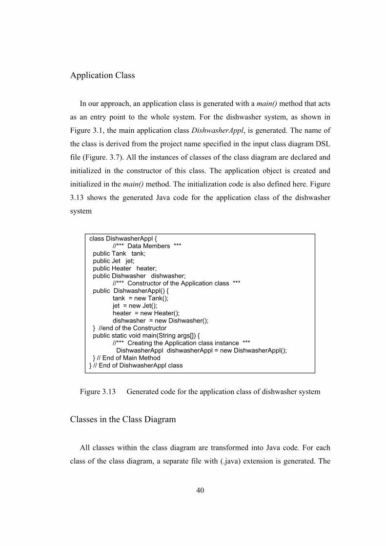
Application Class
In our approach, an application class is generated with a main() method that acts
as an entry point to the whole system. For the dishwasher system, as shown in
Figure 3.1, the main application class DishwasherAppl, is generated. The name of
the class is derived from the project name specified in the input class diagram DSL
file (Figure. 3.7). All the instances of classes of the class diagram are declared and
initialized in the constructor of this class. The application object is created and
initialized in the main() method. The initialization code is also defined here. Figure
3.13 shows the generated Java code for the application class of the dishwasher
system
Figure 3.13 Generated code for the application class of dishwasher system
Classes in the Class Diagram
All classes within the class diagram are transformed into Java code. For each
class of the class diagram, a separate file with (.java) extension is generated. The
class DishwasherAppl { //*** Data Members *** public Tank tank; public Jet jet; public Heater heater; public Dishwasher dishwasher; //*** Constructor of the Application class *** public DishwasherAppl() { tank = new Tank(); jet = new Jet(); heater = new Heater(); dishwasher = new Dishwasher(); } //end of the Constructor public static void main(String args[]) { //*** Creating the Application class instance *** DishwasherAppl dishwasherAppl = new DishwasherAppl(); } // End of Main Method } // End of DishwasherAppl class
41
generated code contains all the class definitions of name, attributes and methods.
Relationships between classes are identified and transformed into code. To
implement the associations between classes, reference attributes with public
visibility are generated in the corresponding classes. If the association is
bidirectional then reference attributes are generated in both classes and if the
association is unidirectional then reference attribute is generated in the source class
only.
If the class has an associated statechart, then the generated code for the class
contains not only the structural code but it also contains the behavioral code for the
class. Additional classes, implementing the state specific behavior, are generated in
the same Java file that implements the context class. To implement a statechart
diagram, the collaborator object approach, described in the chapter 2, is used,
where each state becomes a class and each transition becomes an operation in that
class. The transformation rules are summarized in Table 3. Figure 3.14 shows the
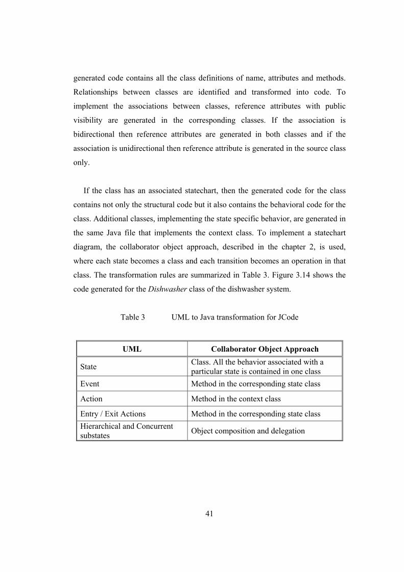
code generated for the Dishwasher class of the dishwasher system.
Table 3 UML to Java transformation for JCode
UML Collaborator Object Approach
State Class. All the behavior associated with a particular state is contained in one class
Event Method in the corresponding state class
Action Method in the context class
Entry / Exit Actions Method in the corresponding state class Hierarchical and Concurrent substates Object composition and delegation
42
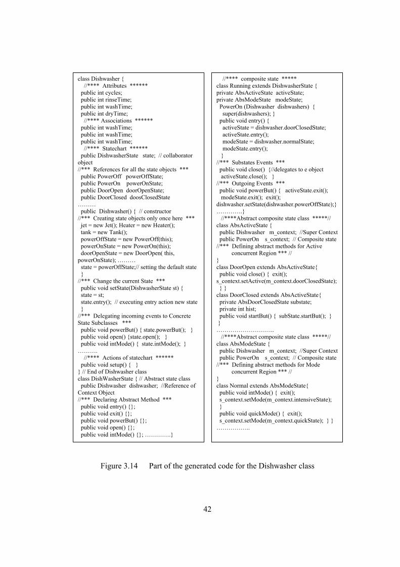
Figure 3.14 Part of the generated code for the Dishwasher class
class Dishwasher { //**** Attributes ****** public int cycles; public int rinseTime; public int washTime; public int dryTime; //**** Associations ****** public int washTime; public int washTime; public int washTime; //**** Statechart ****** public DishwasherState state; // collaborator object //*** References for all the state objects *** public PowerOff powerOffState; public PowerOn powerOnState; public DoorOpen doorOpenState; public DoorClosed doosClosedState ……… public Dishwasher() { // constructor //*** Creating state objects only once here *** jet = new Jet(); Heater = new Heater(); tank = new Tank(); powerOffState = new PowerOff(this); powerOnState = new PowerOn(this); doorOpenState = new DoorOpen( this, powerOnState); ……… state = powerOffState;// setting the default state } //*** Change the current State *** public void setState(DishwasherState st) { state = st; state.entry(); // executing entry action new state } //*** Delegating incoming events to Concrete State Subclasses *** public void powerBut() { state.powerBut(); } public void open() {state.open(); } public void intMode() { state.intMode(); } ………. //**** Actions of statechart ****** public void setup() { } } // End of Dishwasher class class DishWasherState { // Abstract state class public Dishwasher dishwasher; //Reference of Context Object //*** Declaring Abstract Method *** public void entry() {}; public void exit() {}; public void powerBut() {}; public void open() {}; public void intMode() {}; ………….}
//**** composite state ***** class Running extends DishwasherState { private AbsActiveState activeState; private AbsModeState modeState; PowerOn (Dishwasher dishwashers) { super(dishwashers); } public void entry() { activeState = dishwasher.doorClosedState; activeState.entry(); modeState = dishwasher.normalState; modeState.entry(); } //*** Substates Events *** public void close() {//delegates to e object activeState.close(); } //*** Outgoing Events *** public void powerBut() { activeState.exit(); modeState.exit(); exit(); dishwasher.setState(dishwasher.powerOffState);}………….} //****Abstract composite state class *****// class AbsActiveState { public Dishwasher m_context; //Super Context public PowerOn s_context; // Composite state//*** Defining abstract methods for Active concurrent Region *** // } class DoorOpen extends AbsActiveState{ public void close() { exit(); s_context.setActive(m_context.doorClosedState); } } class DoorClosed extends AbsActiveState{ private AbsDoorClosedState substate; private int hist; public void startBut() { subState.startBut(); } } ……………………….. //****Abstract composite state class *****// class AbsModeState { public Dishwasher m_context; //Super Context public PowerOn s_context; // Composite state//*** Defining abstract methods for Mode concurrent Region *** // } class Normal extends AbsModeState{ public void intMode() { exit(); s_context.setMode(m_context.intensiveState); } public void quickMode() { exit(); s_context.setMode(m_context.quickState); } } ……………..
43
Chapter 4
Code Generating System: JCode We have developed the JCode system, which automatically generates Java code
from the specifications of the UML class and statechart diagrams of a system using
our approach. JCode is the successor of OCode. JCode uses state machines of
objects and structural specifications as given in the class diagram of the system and
generates code for the entire application model. It generates the code for the
objects as well as their behavior and action specifications. In this chapter, we
describe the JCode system in detail.
We will use the example of an Air Conditioner application to describe the detail
working of the JCode System. Figure 4.1 shows the static structure of the Air
Conditioner system. The Air Conditioner system consists of six classes, namely
AirCon, DisplayInterface, PowerButton, SpeedButton, ModeButton and
TempButton. The DisplayInterface and AirCon class has a one-to-one association.
The DisplayInterface class has one way aggregation relationships with
PowerButton, ModeButton, SpeedButton and TempButton classes. Aggregation
represents a whole/part relationship. The DisplayInterface represents the “whole”
and PowerButton, ModeButton, SpeedButton and TempButton represent the “part”.
The dynamic behavior of the AirCon class is specified in the statechart diagram as
shown in Figure 4.2.
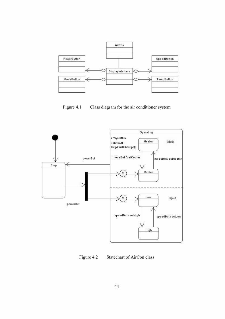
44
Figure 4.1 Class diagram for the air conditioner system
Figure 4.2 Statechart of AirCon class

45
The input to the JCode system is the model specifications in Design Schema
List (DSL) language [29]. The output from the JCode system is the Java [30] code.
JCode is developed in Java and is basically composed of six modules: Main
module, CDAnalyzer, CDTransformer, SCAnalyzer, SCTransformer and
CodeGenerator module. Figure 4.3 shows the overall structure of the JCode system.
Figure 4.3 Structure of the JCode system
4.1 Main Module
The Main module is the main controlling module. The main module takes the
specifications of the class diagram in DSL format as input for the JCode system. It
then calls CDAnalyzer and CDTransformer modules to process the class diagram
DSL file. If a statechart is attached to a class then the CDTransformer module in
Class Diagram DSL file
Statechart Module
Class and State Tables
ClassDiagramModule
Java code
Intermediate Tables
CDAnalyzer
CDTransformer Code Generator
SCAnalyzer
SCTransformer
Statechart DSL file name
Intermediate Tables
State Tables
Statechart DSL file
46
turn calls the SCAnalyzer and SCTransformer modules to process the statechart
DSL file. Finally the main module calls the Code Generator module to generate the
Java code for the entire application model.
A number of classes have been used to form the structure of a nested table and
to represent the elements of the class and statechart diagrams. These classes
include: ClassInfo, MemberData, MemberFunc, Relation, State, Transition, Event,
Argument, Internal Event and Join.
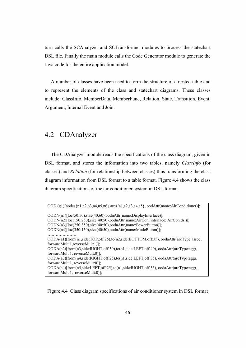
4.2 CDAnalyzer
The CDAnalyzer module reads the specifications of the class diagram, given in
DSL format, and stores the information into two tables, namely ClassInfo (for
classes) and Relation (for relationship between classes) thus transforming the class
diagram information from DSL format to a table format. Figure 4.4 shows the class
diagram specifications of the air conditioner system in DSL format.
Figure 4.4 Class diagram specifications of air conditioner system in DSL format
OOD (g1)[nodes{n1,n2,n3,n4,n5,n6},arcs{a1,a2,a3,a4,a5}, oodAttr(name:AirConditioner)]; OODN(n1)[loc(50:50),size(40:60),oodnAttr(name:DisplayInterface)]; OODN(n2)[loc(150:250),size(40:50),oodnAttr(name:AirCon, interface: AirCon.dsl)]; OODN(n3)[loc(250:350),size(40:50),oodnAttr(name:PowerButton)]; OODN(n4)[loc(350:150),size(40:50),oodnAttr(name:ModeButton)]; ………………… OODA(a1)[from(n1,side:TOP,off:25),to(n2,side:BOTTOM,off:35), oodaAttr(arcType:assoc, forwardMult:1,reverseMult:1)]; OODA(a2)[from(n3,side:RIGHT,off:30),to(n1,side:LEFT,off:40), oodaAttr(arcType:aggr, forwardMult:1, reverseMult:0)]; OODA(a3)[from(n4,side:RIGHT,off:25),to(n1,side:LEFT,off:35), oodaAttr(arcType:aggr, forwardMult:1, reverseMult:0)]; OODA(a4)[from(n5,side:LEFT,off:25),to(n1,side:RIGHT,off:35), oodaAttr(arcType:aggr, forwardMult:1, reverseMult:0)];
47
The CDAnalyzer module has a number of methods. The most important
methods are readCDFile, analyzerCD and analyzeCDLine. Following is the
brief description of the functionality of these methods.
The readCDFile Method
The readCDFile method reads the DSL file character by character, throws all
the white spaces and creates a long string that contains all the DSL statements of
the class diagram. It stores the long string in a variable, dataCDFile, of type String.
It passes this long string to the analyzerCD method for processing the class
diagram.
The analyzerCD Method
This method takes the class diagram DSL file as a long string and splits the long
string into several small strings, each representing a DSL statement. A DSL
statement always ends on a semicolon, so the DSL file string is split on semicolons.
Each string, which represents a DSL statement, becomes an element of an array.
The analyzerCD method then starts a loop which calls the analyzeCDLine
method (explained below) for each element of this string array and passes the
string as argument.
The analyzeCDLine Method
This is a long method which takes a string, representing a DSL statement, as
arguments and analyzes it. It collects the information contained in the DSL
statement and, based on this information instantiates objects of ClassInfo and
Relation classes and stores the information into these two tables. Nodes in DSL
represent the classes. All the information about the classes is stored in the
48
ClassInfo table. Arcs in DSL represent the relationships among classes. All the
information about the relationships is stored in the Relation table. For example
after reading the following DSL statement
OODN(n2)[loc(150:250),size(40:50),oodnAttr(name:AirCon, interface: AirCon.dsl)]
a ClassInfo object having the values of its id attribute as “n2” will be searched. If
the object does not exist, it will be created. The name attribute will be initialized
with the value “AirCon” and the statechartFileName attribute will be initialized
with the value “AirCon.dsl”. Figure 4.5 shows the part of the ClassInfo table of the
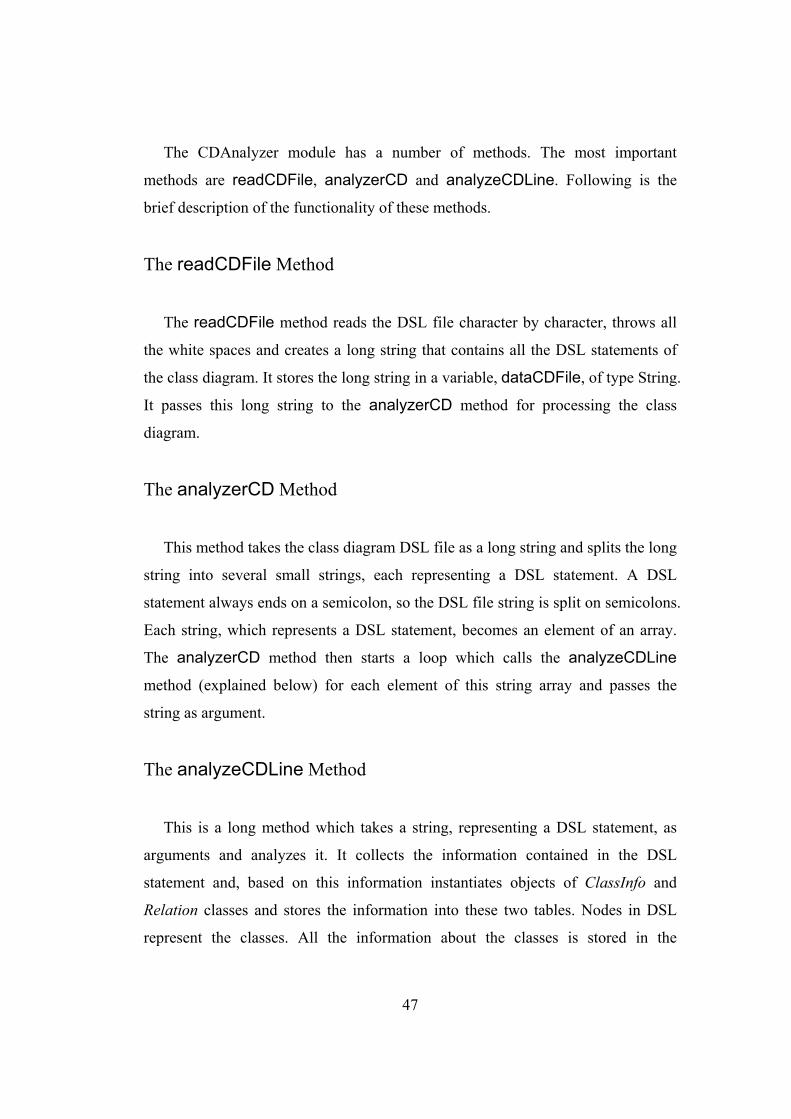
air conditioner system.
Data members Class
ID Class Name
Visibility Name Type Statechart DSL Filename
n1 DisplayInterface n2 AirCon AirCon.dsl n3 PowerButton n4 ModeButton n5 SpeedButton n6 TempButton
Figure 4.5 Part of the ClassInfo table for air conditioner system
4.3 CDTransformer
After the CDAnalyzer module does its job, the information contained in the
DSL file is converted into an intermediate form in which the class diagram
elements are represented as object instances. This information, however, is
unorganized and needs to be transformed. DSL, being graphical oriented, treats
relations as arcs so we need to process the Relation table and update the ClassInfo
table to properly record the information for code generation.
49
The processRelation Method
This method processes the Relation table and updates the ClassInfo table for
relationship between classes. If the relationship is of type inheritance then the child
class attribute inherit is set to true and the name of the parent class is also set in the
parent attribute of the child class. If the relationship is of type aggregation or
association then the multiplicity on both ends is checked and relationship attributes
are added in the respective classes.
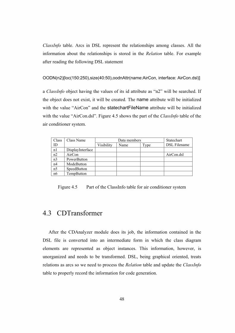
The CDTransformer module then process the ClassInfo table and extracts the
statechart DSL filenames and passes this information to the SCAnalyzer module
for processing the statechart DSL file. Figure 4.6 shows the statechart DSL
filenames for the air conditioner system passed to the SCAnalyzer module.
Class ID Class Name Statechart DSL Filename
n1 DisplayInterface n2 AirCon AirCon.dsl n3 PowerButton n4 ModeButton n5 SpeedButton n6 TempButton
Figure 4.6 Statechart DSL filenames for classes of air conditioner system
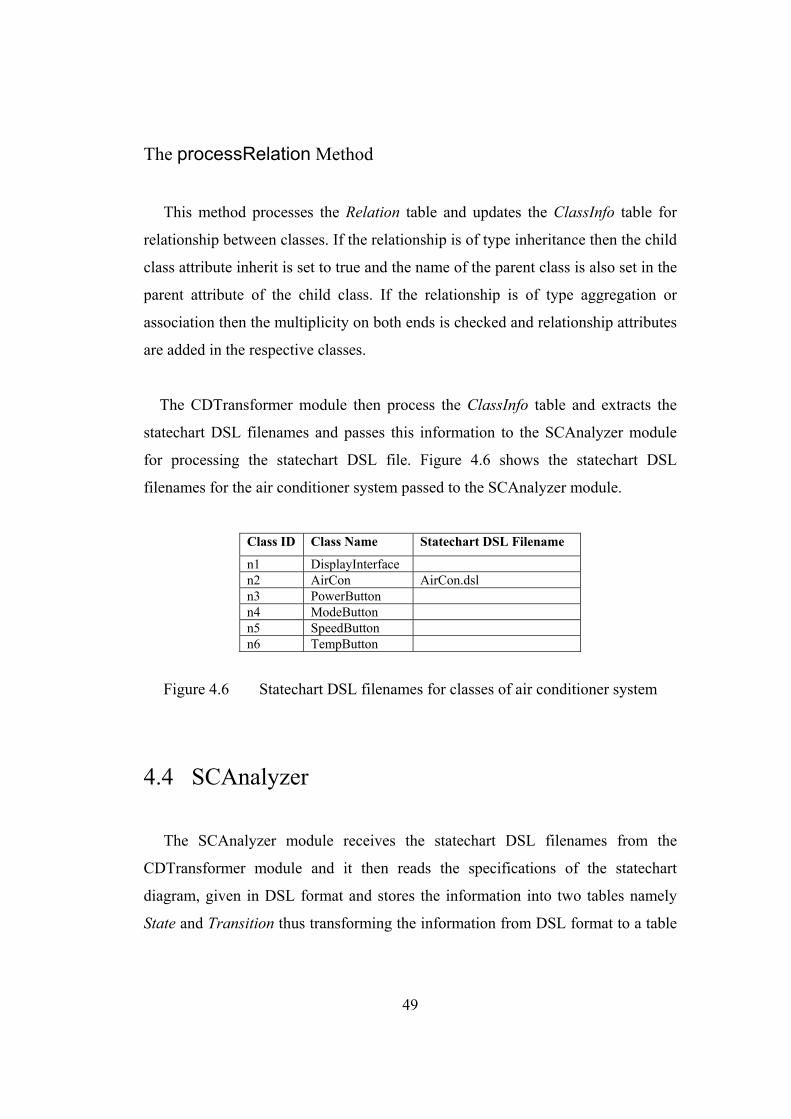
4.4 SCAnalyzer
The SCAnalyzer module receives the statechart DSL filenames from the
CDTransformer module and it then reads the specifications of the statechart
diagram, given in DSL format and stores the information into two tables namely
State and Transition thus transforming the information from DSL format to a table
50
format. Figure 4.7 shows the statechart specifications of AirCon class in DSL
format.
Figure 4.7 Statechart specifications of AirCon class in DSL format
The SCAnalyzer module has a number of methods. The most important methods
are readSCFile, analyzerSC and analyzeSCLine. Following is the brief
description of the functionality of these methods.
The readSCFile Method
This readSCFile method reads the statechart DSL file character by character,
throws all the white spaces and creates a long string that contains all the DSL
statements. It stores the long string in a variable, dataSCFile, of type String. It
passes this long string to the analyzerSC method for processing the statechart
diagram.
OSTD (AirCon)[nodes{n1,n2,n3,n4,n5,n6,n7,n8,n9,n10,n11,n12},arcs{a1,a2,a3,a4,a5,a6, a7, a8, a9,a10,a11}]; OSTDN(n1)[loc(25:20),size(20:20),ostdnAttr(name:START)]; OSTDN(n2)[loc(10:140),size(75:125),ostdnAttr(name:Stop)]; OSTDN(n3)[loc(125:160),size(10:100),ostdnAttr(name:FORK)]; OSTDN(n4)[loc(160:10),size(260:400),ostdnAttr(name:Operating,entry/setOn,exit/setOff, event(name:tempPlusBut)/tempUp,concurrent{n5,n9})]; OSTDN(n5)[loc(160:20),size(260:180),ostdnAttr(name:Mode,substates{n6,n7,n8})]; OSTDN(n6)[loc(190:150),size(30:25),ostdnAttr(name:HISTORY)]; …………………………………………….. OSTDA(a1)[from(n1,side:BOTTOM,off:5),to(n2,side:TOP,off:40)]; OSTDA(a2)[from(n2,side:RIGHT,off:35),to(n3,side:LEFT,off:140),ostdaAttr(name:powerBut)]; ………………………………………………
51
The analyzerSC Method
This method takes the DSL file of the statechart as a long string from the
readSCFile method and splits the long string into several small strings each
representing a DSL statement. A DSL statement always ends on a semicolon, so
the DSL file string is split on semicolons. Each string, which represents a DSL
statement, becomes an element of an array. The analyzerSC method then starts a
loop which calls the analyzeSCLine method (explained below) for each string
and passes the string as argument.
The analyzeSCLine Method
This is a long method which takes a string, representing a DSL statement, as
argument and analyzes it. It collects the information contained in the DSL
statement and, based on this information instantiates objects of State and
Transition classes and stores the information into these two tables for the class
with which the statechart is attached. Nodes in DSL of the statechart diagram
represent the states. All the information about the states is stored in the State table.
Arcs in DSL of the statechart diagram represent the transitions of the statecharts.
All the information about the transitions is stored in the Transition table. For
example after reading the following DSL statement
OSTDN(n4)[loc(160:10),size(260:400),ostdnAttr(name:Operating,entry/setOn,exit/setOff,event(name:tempPlusBut)/tempUp,concurrent{n5,n9})]
a State object having the values of its id attribute as “n4” will be searched. If the
object does not exist, it will be created. The name attribute will be initialized with
the value “Operating” and the type of state is set to concurrent. The substate
attribute which is an array of pointers to other State objects and represents the
52
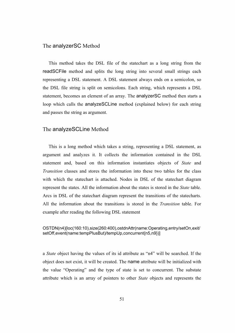
substates of the current state will contain pointers to the State objects having ids
“n5” and “n9”. Similarly the information about the transitions, which includes
name of the triggering event, event action, source state and target state, is stored in
the Transition table. Figure 4.8 shows the part of the State table for the statechart
diagram of the AirCon class.
Outgoing Transitions State
ID State Name
Substates Internal Event ID Event Action Next
Staten1 START a1 n2 n2 Stop a2 powerBut n3
a3 n6 n3 FORK a4 n10
n4 Operating n5, n9 tempPlusBut / tempUp()
a5 powerBut n2
n5 Mode n6, n7, n8 n7 HISTORY a6 n7 n7 Cooler a7 modeBut setHeater n8 n8 Heater a8 modeBut setCooler n7 n9 Speed n10, n11, n12 n10 HISTORY a9 n11 n11 Low a10 speedBut setHigh n12 n12 High a11 speedBut setLow n11
Figure 4.8 Part of the state table for statechart of AirCon Class
4.5 SCTransformer
After the SCAnalyzer module does its job, the information contained in the
DSL file is converted into an intermediate form in which the state diagram
elements are represented as object instances. This information, however, is
unorganized and needs to be transformed. For example, in a statechart diagram, the
pseudostates (e.g. Start state, history, fork, join etc.) are shown with their special
symbols. DSL, being graphical oriented, treats them as a node like any other node
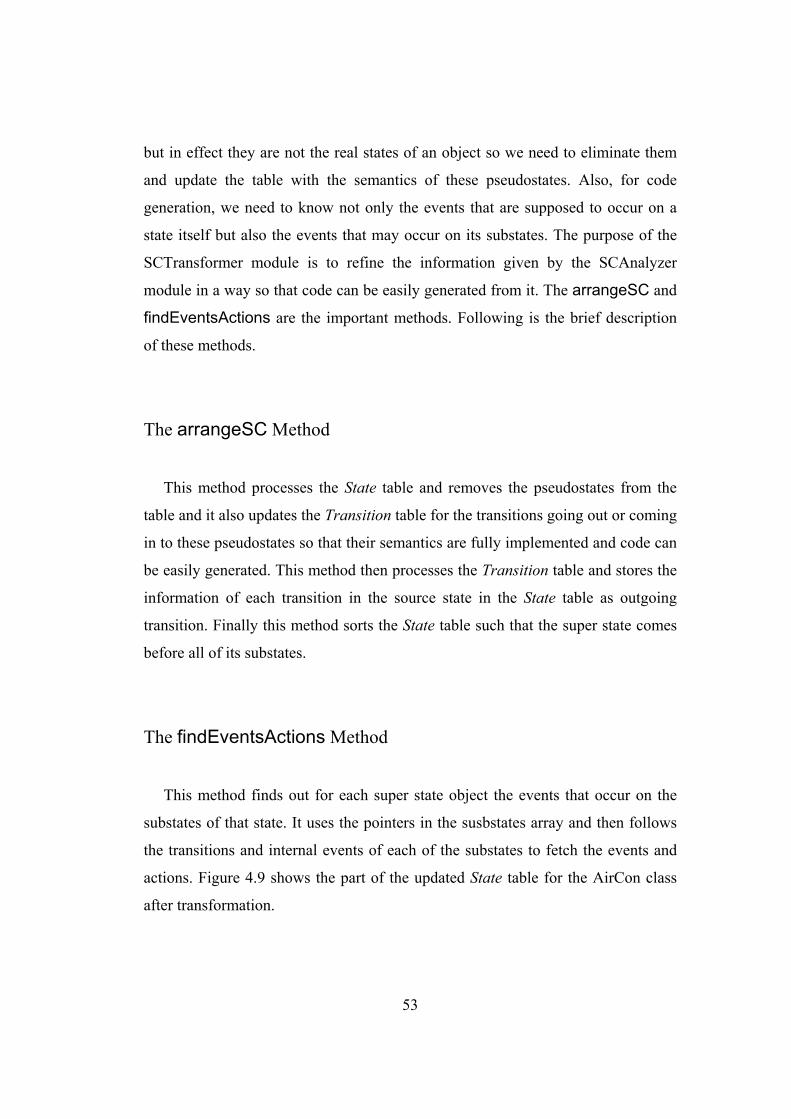
53
but in effect they are not the real states of an object so we need to eliminate them
and update the table with the semantics of these pseudostates. Also, for code
generation, we need to know not only the events that are supposed to occur on a
state itself but also the events that may occur on its substates. The purpose of the
SCTransformer module is to refine the information given by the SCAnalyzer
module in a way so that code can be easily generated from it. The arrangeSC and
findEventsActions are the important methods. Following is the brief description
of these methods.
The arrangeSC Method
This method processes the State table and removes the pseudostates from the
table and it also updates the Transition table for the transitions going out or coming
in to these pseudostates so that their semantics are fully implemented and code can
be easily generated. This method then processes the Transition table and stores the
information of each transition in the source state in the State table as outgoing
transition. Finally this method sorts the State table such that the super state comes
before all of its substates.
The findEventsActions Method
This method finds out for each super state object the events that occur on the
substates of that state. It uses the pointers in the susbstates array and then follows
the transitions and internal events of each of the substates to fetch the events and
actions. Figure 4.9 shows the part of the updated State table for the AirCon class
after transformation.
54
Outgoing Transitions State ID
State Name *=default +=history
Substates Substate Events ID Event Action Next
Staten2 Stop* a2 powerBut n4 n4 Operating n5, n9 modeBut,
speedBut a5 powerBut n2
n5 Mode+ n7, n8 modeBut n7 Cooler* a7 modeBut setHeater n8 n8 Heater a8 modeBut setCooler n7 n9 Speed+ n11, n12 speedBut n11 Low* a10 speedBut setHigh n12 n12 High a11 speedBut setLow n11
Figure 4.9 Part of the updated state table for statechart of AirCon class.
The SCTransformer module then passes the transformed State table back to the
CDTransformer module. The State table is stored in the ClassInfo table along with
other information of the corresponding class. Figure 4.10 shows the part of the
ClassInfo table for the air conditioner system after the processing of the
SCTransformer module.
Data members Class
ID Class Name
Visibility Name Type State Table
public airCon AirCon public powerButton PowerButton public modeButton ModeButton public speedButton SpeedButton
n1
DisplayInterface
public tempButton TempButton
n2 AirCon public displayInterface DisplayInterface AirCon state table
n3 PowerButton n4 ModeButton n5 SpeedButton n6 TempButton
Figure 4.10 Part of the updated ClassInfo table for air conditioner system
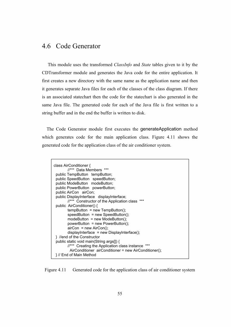
55
4.6 Code Generator
This module uses the transformed ClassInfo and State tables given to it by the
CDTransformer module and generates the Java code for the entire application. It
first creates a new directory with the same name as the application name and then
it generates separate Java files for each of the classes of the class diagram. If there
is an associated statechart then the code for the statechart is also generated in the
same Java file. The generated code for each of the Java file is first written to a
string buffer and in the end the buffer is written to disk.
The Code Generator module first executes the generateApplication method
which generates code for the main application class. Figure 4.11 shows the
generated code for the application class of the air conditioner system.
Figure 4.11 Generated code for the application class of air conditioner system
class AirConditioner { //*** Data Members *** public TempButton tempButton; public SpeedButton speedButton; public ModeButton modeButton; public PowerButton powerButton; public AirCon airCon; public DisplayInterface displayInterface; //*** Constructor of the Application class *** public AirConditioner() { tempButton = new TempButton(); speedButton = new SpeedButton(); modeButton = new ModeButton(); powerButton = new PowerButton(); airCon = new AirCon(); displayInterface = new DisplayInterface(); } //end of the Constructor public static void main(String args[]) { //*** Creating the Application class instance *** AirConditioner airConditioner = new AirConditioner(); } // End of Main Method
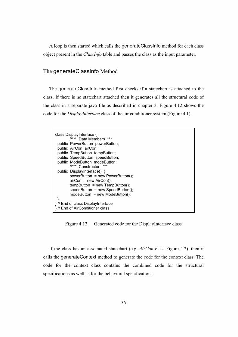
56
A loop is then started which calls the generateClassInfo method for each class
object present in the ClassInfo table and passes the class as the input parameter.
The generateClassInfo Method
The generateClassInfo method first checks if a statechart is attached to the
class. If there is no statechart attached then it generates all the structural code of
the class in a separate java file as described in chapter 3. Figure 4.12 shows the
code for the DisplayInterface class of the air conditioner system (Figure 4.1).
Figure 4.12 Generated code for the DisplayInterface class
If the class has an associated statechart (e.g. AirCon class Figure 4.2), then it
calls the generateContext method to generate the code for the context class. The
code for the context class contains the combined code for the structural
specifications as well as for the behavioral specifications.
class DisplayInterface { //*** Data Members *** public PowerButton powerButton; public AirCon airCon; public TempButton tempButton; public SpeedButton speedButton; public ModeButton modeButton; //*** Constructor *** public DisplayInterface() { powerButton = new PowerButton(); airCon = new AirCon(); tempButton = new TempButton(); speedButton = new SpeedButton(); modeButton = new ModeButton(); } } // End of class DisplayInterface } // End of AirConditioner class
57
The generateContext Method
The generateContext method generates the Java code for the class attributes,
associations, methods and it also includes code for attached statechart according to
the collaborator object approach as described in chapter 2. First of all code for all
the attributes and associations of the context class are generated. Then collaborator
object state and all the state objects are defined. The constructor is then generated.
All the state objects are created once in the constructor. The collaborator object
state is also initialized to the default state in the constructor. All the events of the
statechart become methods in the context class. The body of these methods
contains only a statement which delegates the event to the collaborator object. All
the actions of the statechart become methods in the context class. The body code of
the actions methods has to be entered by the user. Finally the code for the member
functions of the context class is generated.
An abstract state class is generated in the same Java file. The name of the
context attribute is derived from the context class name and “State” is added to it.
The abstract state class contains an attribute for the context object and also
contains empty declarations for the entry/exit actions and all the events of the
statechart diagram.
After this the generateContext method processes the State table of that class in
a loop and calls the following methods according to the type of the state.
The generateState Method
The generateState method generates the code for the top level states having
no super state. A class is generated for each state. The name of the class is derived
from the name of the state. The state class is derived from the abstract state class.

58
If the state has entry/exit actions, methods having the name entry and exit
respectively, are defined in the state class. Bodies of these methods contain a
method-call to the corresponding entry/exit actions. The code for internal events
and outgoing transitions (if any) is also generated. An event on any substate
becomes a method in the corresponding substate class. Body code for the method
is also completely generated. If the event is an internal event, the body code
contains a method-call, which executes the associated action. If the event has a
transition, the body code also contains: (i) call to the exit operation of the current
state, (ii) method-call for setting the next state, which in turn calls the entry actions
of the new state.
The generateHierarchical Method
The generateHierarchical method generates the code for the hierarchical
composite state class in the same Java file as the context class. The hierarchical
composite state class contains a single collaborator object subState. The entry
method is also defined which sets the default active substate. Also, an exit method
is defined which contains a call to the exit actions of the active substate It also
contains the code for storing the active substate in the history state attribute. For
each event on the substates, a method is defined that delegates the event processing
to the substate and calls the method(s) for that event defined in the class(es) for the
substate(s). It also contains methods for setting the next substate and calling the
entry action of the next substate.
The generateConcurrent Method
The generateConcurrent method generates the code for the concurrent
composite state class in the same Java file as context class. The concurrent
composite state, class contains as many collaborator objects as there are concurrent

59
regions in the composite state. The composite state class is responsible for
implementing the fork. Also, an exit method is defined which contains a call to the
exit actions of the active substates in each of the concurrent regions. It also
contains the code for storing the active substate in the history state attribute. For
each event on the substates, a method is defined that delegates the event processing
to the substate and calls the method(s) for that event defined in the class(es) for the
substate(s). It also contains methods for setting the next substate and calling the
entry action of the next substate.
The generateRegion Method
The generateConcurrent method generates code for the concurrent region.
The concurrent region becomes a composite abstract class and serves as an
interface for its own subclasses. This class is not derived from any other class. In
addition to the entry and exit operations, it contains empty declarations for
operations corresponding to its substates. It also contains two objects, namely
m_context and s_context. m_context provides access to the context class for
executing the actions associated with events and entry/exit operations and
s_context provides access to the composite state class to change the next substate.
The generateSubState Method
The generateSubState method generates the code for the substate. A class is
generated for each substate. The name of the class is derived from the name of the
substate. The state class is derived from the composite abstract state class. If the
state has entry/exit actions, methods having the name entry and exit respectively,
are defined in the state class. Bodies of these methods contain a method-call to the
corresponding entry/exit actions. The code for internal events and outgoing
transitions (if any) is also generated.

60
class AirCon { // context class DisplayInterface displayInterface; // date member public AirConState state; // collaborator object public Stop stopState; public Operating operatingState; public Cooler coolerState; public Heater heaterState; public Low lowState; public High highState; AirCon() { //constructor stopState = new Stop(this); operatingState = new Operating(this); coolerState = new Cooler(this,operatingState); heaterState = new Heater(this,operatingState); lowState = new Low(this,operatingState); highState = new High(this,operatingState); state = stopState // setting default state } public void setState(AirConState st) { state = st; state.entry(); } public powerBut() { state.powerBut(); } public modeBut() {state.modeBut(); } …………………. public void setOff() {……} public void setCooler() {……} ………} public AirConState { // abstract state class public AirCon airCon; // context reference public void entry() {}; public void exit() {}; public void powerBut() {}; public void tempPlusBut() {}; …………..}
class Operating extends AirConState{ // composite private AbsModeState modeState; private AbsModeState modeHistory; private AbsSpeedState speedState; private AbsSpeedState speedHistory; int hist = 0; public void entry() { if (hist > 0) {// last active substate modeState = modeHistory; speedState = speedHistory; } else { // for first time entry modeState = airCon.coolerState; speedState = airCon.lowState; } modeState.entry(); speedState.entry(); airCon.setOn(); } public void exit() {airCon.setOff; modeHistory = modeState; speedHistory = speedState; } public void modeBut() { modeState.modeBut(); } public void speedBut() { speedState.speedBut(); public void powerBut() {modeState.exit(); speedState.exit(); exit(); airCon.setState(ac.stopState); } public void setMode(AbsModeState subMode) { modeState = subMode; modeState.entry(); }...} class AbsModeState { // abstract composite state public AirCon m_context; public Operating s_context; /* Empty declarations for entry(), exit() and all events methods of subclasses of AbsModeState*/ } class Cooler extends AbsModeState{//substate class void modeBut() { m_context.setCooler(); exit(); s_context.setMode(m_context.heaterState); } }
Figure 4.13 shows part of the code generated by JCode for the AirCon class of the
air conditioner system.
Figure 4.13 Part of the generated code for the AirCon class
61
Chapter 5
Implementing Other Features of Statechart Diagram The statechart diagram, when attached to a class, shows all the behavioral
aspects of the objects in that class. Concurrent substates not only represent the
inherent parallelism in some of the objects but also enable compact descriptions of
the complex state diagrams [20, 21]. This chapter discusses the other features of
statechart diagram such as fork, join and history state and how our proposed
approach implement these features in our code generating system JCode.
5.1 Fork and Join
Fork and join pseudostates synchronize transitions entering or leaving
orthogonal regions of the concurrent composite state. A fork is a transition with
one source state and two or more target states. If the source state is active and the
trigger event occurs, the transition action is executed and all the target states
become active. A join is a transition with two or more source states and one target
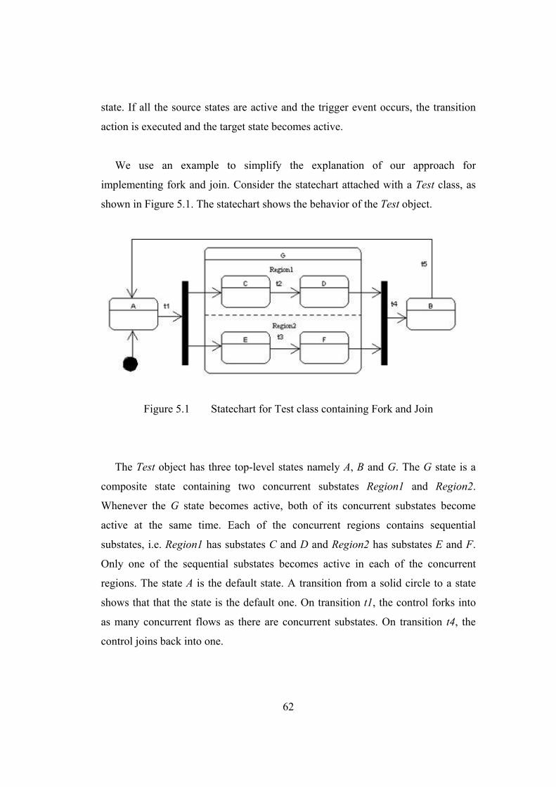
62
state. If all the source states are active and the trigger event occurs, the transition
action is executed and the target state becomes active.
We use an example to simplify the explanation of our approach for
implementing fork and join. Consider the statechart attached with a Test class, as
shown in Figure 5.1. The statechart shows the behavior of the Test object.
Figure 5.1 Statechart for Test class containing Fork and Join
The Test object has three top-level states namely A, B and G. The G state is a
composite state containing two concurrent substates Region1 and Region2.
Whenever the G state becomes active, both of its concurrent substates become
active at the same time. Each of the concurrent regions contains sequential
substates, i.e. Region1 has substates C and D and Region2 has substates E and F.
Only one of the sequential substates becomes active in each of the concurrent
regions. The state A is the default state. A transition from a solid circle to a state
shows that that the state is the default one. On transition t1, the control forks into
as many concurrent flows as there are concurrent substates. On transition t4, the
control joins back into one.
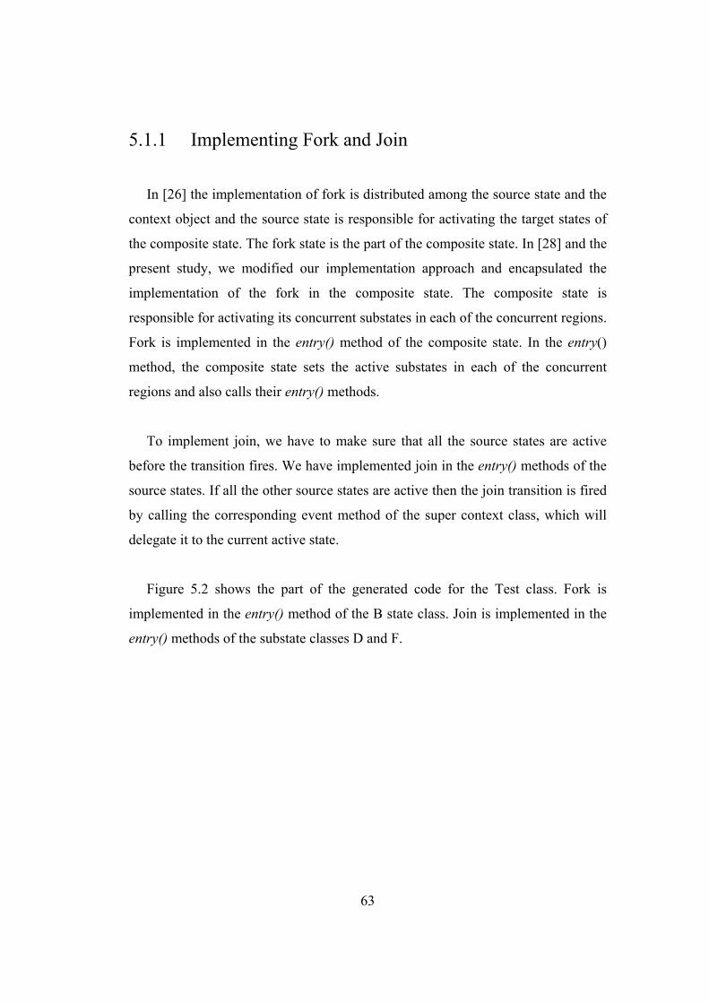
63
5.1.1 Implementing Fork and Join
In [26] the implementation of fork is distributed among the source state and the
context object and the source state is responsible for activating the target states of
the composite state. The fork state is the part of the composite state. In [28] and the
present study, we modified our implementation approach and encapsulated the
implementation of the fork in the composite state. The composite state is
responsible for activating its concurrent substates in each of the concurrent regions.
Fork is implemented in the entry() method of the composite state. In the entry()
method, the composite state sets the active substates in each of the concurrent
regions and also calls their entry() methods.
To implement join, we have to make sure that all the source states are active
before the transition fires. We have implemented join in the entry() methods of the
source states. If all the other source states are active then the join transition is fired
by calling the corresponding event method of the super context class, which will
delegate it to the current active state.
Figure 5.2 shows the part of the generated code for the Test class. Fork is
implemented in the entry() method of the B state class. Join is implemented in the
entry() methods of the substate classes D and F.
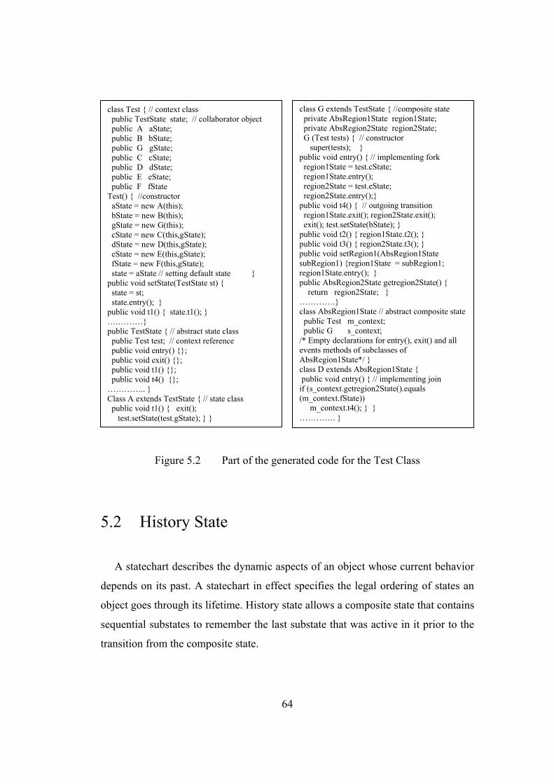
64
Figure 5.2 Part of the generated code for the Test Class
5.2 History State
A statechart describes the dynamic aspects of an object whose current behavior
depends on its past. A statechart in effect specifies the legal ordering of states an
object goes through its lifetime. History state allows a composite state that contains
sequential substates to remember the last substate that was active in it prior to the
transition from the composite state.
class G extends TestState { //composite state private AbsRegion1State region1State; private AbsRegion2State region2State; G (Test tests) { // constructor super(tests); } public void entry() { // implementing fork region1State = test.cState; region1State.entry(); region2State = test.eState; region2State.entry();} public void t4() { // outgoing transition region1State.exit(); region2State.exit(); exit(); test.setState(bState); } public void t2() { region1State.t2(); } public void t3() { region2State.t3(); } public void setRegion1(AbsRegion1State subRegion1) {region1State = subRegion1; region1State.entry(); } public AbsRegion2State getregion2State() { return region2State; } ………….} class AbsRegion1State // abstract composite state public Test m_context; public G s_context; /* Empty declarations for entry(), exit() and all events methods of subclasses of AbsRegion1State*/ } class D extends AbsRegion1State { public void entry() { // implementing join if (s_context.getregion2State().equals (m_context.fState)) m_context.t4(); } } …………. }
class Test { // context class public TestState state; // collaborator object public A aState; public B bState; public G gState; public C cState; public D dState; public E eState; public F fState Test() { //constructor aState = new A(this); bState = new B(this); gState = new G(this); cState = new C(this,gState); dState = new D(this,gState); eState = new E(this,gState); fState = new F(this,gState); state = aState // setting default state } public void setState(TestState st) { state = st; state.entry(); } public void t1() { state.t1(); } ….………} public TestState { // abstract state class public Test test; // context reference public void entry() {}; public void exit() {}; public void t1() {}; public void t4() {}; ………….. } Class A extends TestState { // state class public void t1() { exit(); test.setState(test.gState); } }
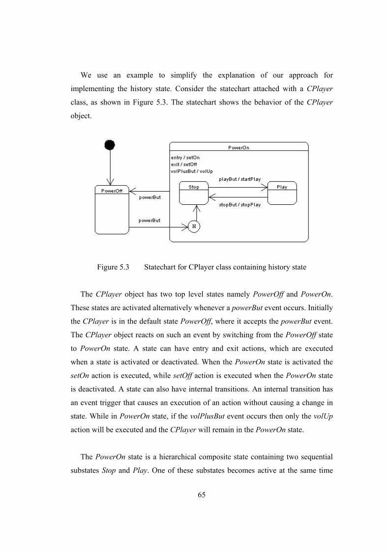
65
We use an example to simplify the explanation of our approach for
implementing the history state. Consider the statechart attached with a CPlayer
class, as shown in Figure 5.3. The statechart shows the behavior of the CPlayer
object.
Figure 5.3 Statechart for CPlayer class containing history state
The CPlayer object has two top level states namely PowerOff and PowerOn.
These states are activated alternatively whenever a powerBut event occurs. Initially
the CPlayer is in the default state PowerOff, where it accepts the powerBut event.
The CPlayer object reacts on such an event by switching from the PowerOff state
to PowerOn state. A state can have entry and exit actions, which are executed
when a state is activated or deactivated. When the PowerOn state is activated the
setOn action is executed, while setOff action is executed when the PowerOn state
is deactivated. A state can also have internal transitions. An internal transition has
an event trigger that causes an execution of an action without causing a change in
state. While in PowerOn state, if the volPlusBut event occurs then only the volUp
action will be executed and the CPlayer will remain in the PowerOn state.
The PowerOn state is a hierarchical composite state containing two sequential
substates Stop and Play. One of these substates becomes active at the same time
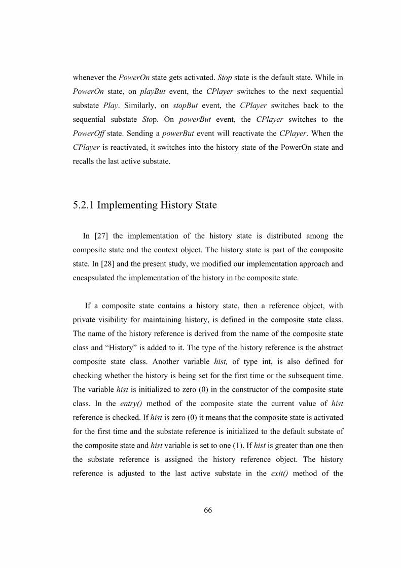
66
whenever the PowerOn state gets activated. Stop state is the default state. While in
PowerOn state, on playBut event, the CPlayer switches to the next sequential
substate Play. Similarly, on stopBut event, the CPlayer switches back to the
sequential substate Stop. On powerBut event, the CPlayer switches to the
PowerOff state. Sending a powerBut event will reactivate the CPlayer. When the
CPlayer is reactivated, it switches into the history state of the PowerOn state and
recalls the last active substate.
5.2.1 Implementing History State
In [27] the implementation of the history state is distributed among the
composite state and the context object. The history state is part of the composite
state. In [28] and the present study, we modified our implementation approach and
encapsulated the implementation of the history in the composite state.
If a composite state contains a history state, then a reference object, with
private visibility for maintaining history, is defined in the composite state class.
The name of the history reference is derived from the name of the composite state
class and “History” is added to it. The type of the history reference is the abstract
composite state class. Another variable hist, of type int, is also defined for
checking whether the history is being set for the first time or the subsequent time.
The variable hist is initialized to zero (0) in the constructor of the composite state
class. In the entry() method of the composite state the current value of hist
reference is checked. If hist is zero (0) it means that the composite state is activated
for the first time and the substate reference is initialized to the default substate of
the composite state and hist variable is set to one (1). If hist is greater than one then
the substate reference is assigned the history reference object. The history
reference is adjusted to the last active substate in the exit() method of the
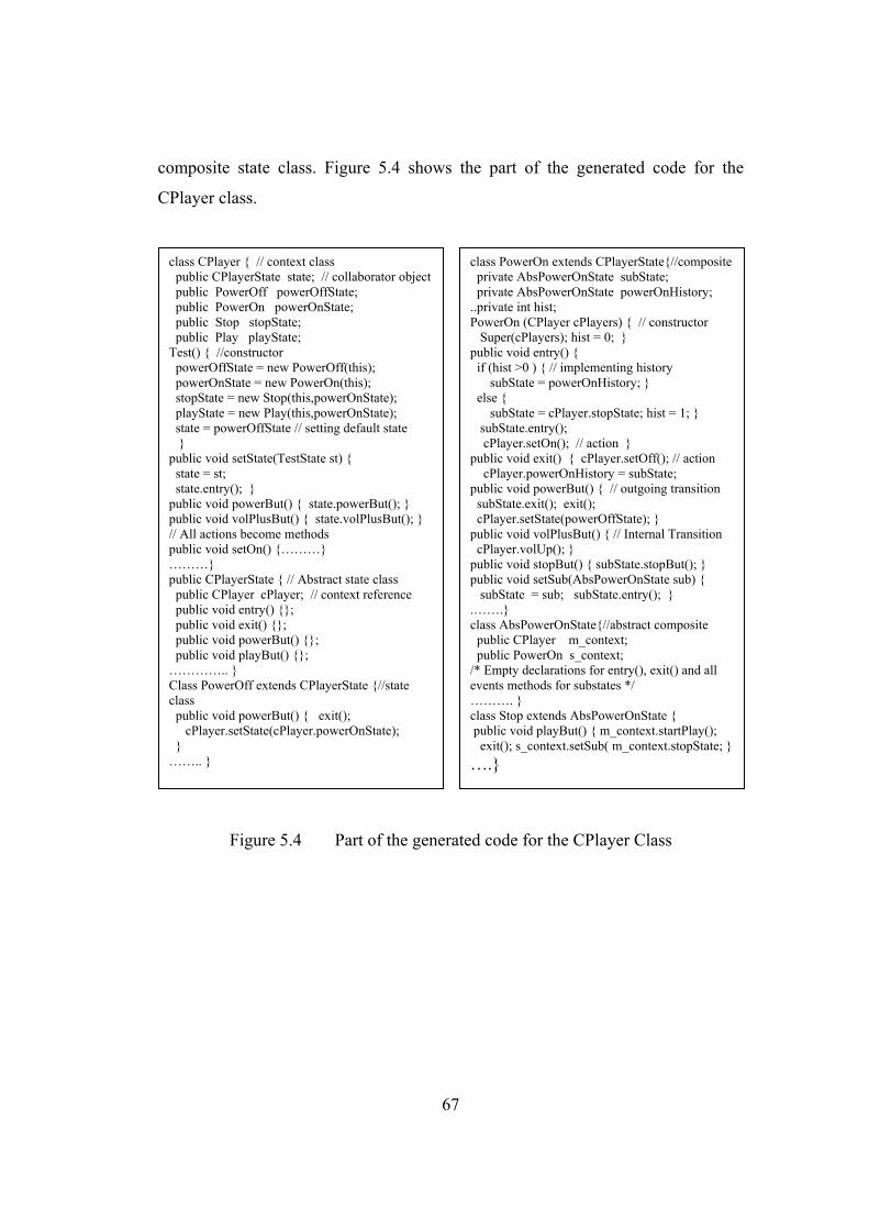
67
composite state class. Figure 5.4 shows the part of the generated code for the
CPlayer class.
Figure 5.4 Part of the generated code for the CPlayer Class
class CPlayer { // context class public CPlayerState state; // collaborator object public PowerOff powerOffState; public PowerOn powerOnState; public Stop stopState; public Play playState; Test() { //constructor powerOffState = new PowerOff(this); powerOnState = new PowerOn(this); stopState = new Stop(this,powerOnState); playState = new Play(this,powerOnState); state = powerOffState // setting default state } public void setState(TestState st) { state = st; state.entry(); } public void powerBut() { state.powerBut(); } public void volPlusBut() { state.volPlusBut(); } // All actions become methods public void setOn() {………} ………} public CPlayerState { // Abstract state class public CPlayer cPlayer; // context reference public void entry() {}; public void exit() {}; public void powerBut() {}; public void playBut() {}; ………….. } Class PowerOff extends CPlayerState {//state class public void powerBut() { exit(); cPlayer.setState(cPlayer.powerOnState); } …….. }
class PowerOn extends CPlayerState{//composite private AbsPowerOnState subState; private AbsPowerOnState powerOnHistory; ..private int hist; PowerOn (CPlayer cPlayers) { // constructor Super(cPlayers); hist = 0; } public void entry() { if (hist >0 ) { // implementing history subState = powerOnHistory; } else { subState = cPlayer.stopState; hist = 1; } subState.entry(); cPlayer.setOn(); // action } public void exit() { cPlayer.setOff(); // action cPlayer.powerOnHistory = subState; public void powerBut() { // outgoing transition subState.exit(); exit(); cPlayer.setState(powerOffState); } public void volPlusBut() { // Internal Transition cPlayer.volUp(); } public void stopBut() { subState.stopBut(); } public void setSub(AbsPowerOnState sub) { subState = sub; subState.entry(); } .…….} class AbsPowerOnState{//abstract composite public CPlayer m_context; public PowerOn s_context; /* Empty declarations for entry(), exit() and all events methods for substates */ ………. } class Stop extends AbsPowerOnState { public void playBut() { m_context.startPlay(); exit(); s_context.setSub( m_context.stopState; }….}
68
Chapter 6
Comparison With Rhapsody and OCode Rhapsody [19, 20, 21], which is a successor of STATEMATE [22], is a CASE
tool that allows creating UML models for an application and then generates C,
C++ or Java code for the application. Rhapsody generates code from UML class
and statechart diagrams. It follows an approach similar to switch statement
approach, described in chapter 2, to implement UML statechart diagram. Rhapsody
uses Object eXecution Framework (OXF) [19] for code generation.
OCode [24, 25] is another tool for code generation from Object Modeling
Technique (OMT) [6, 31, 32, 33] dynamic models. OCode uses an approach
similar to helper object approach to generate code for OMT state transition
diagram. OMT state transition diagram is the predecessor of UML statechart
diagram. UML statechart diagram contains many features which are not present in
OMT state transition diagram, e.g. history states, fork and join, time events etc.
JCode is the successor of OCode.
We will now compare the code generated by JCode with that of Rhapsody and
OCode. We generated code for six different applications. To compare the

69
efficiency of the code generated by Rhapsody, OCode and JCode, we performed an
experiment in which the same sequence of 4000 requests was sent. Out of these
4000 events, some caused transitions while the remaining events did not cause any
transition and were ignored. For each event, the time taken to process the event
was calculated. We made all the actions methods empty and concentrated on
measuring the time taken while executing transitions, i.e. changing states. To have
more accurate results, we repeated the experiment 20 times and calculated the
average values. The experiment was performed on a Sun SPARC workstation.
6.1 Watch Application
Figure 6.1 shows the static structure of the Watch application. The Watch
application consists of five classes namely Watch, DisplayArea, SetButton,
UpButton and ModeButton. The dynamic behavior of the Watch class is specified
in the statechart as shown in Figure 6.2. Table 4 shows the compactness of the
code generated by Rhapsody and JCode. Table 5 shows the comparison of
efficiency of the code generated by Rhapsody, OCode and JCode for watch
application.
Figure 6.1 Class diagram for the watch application
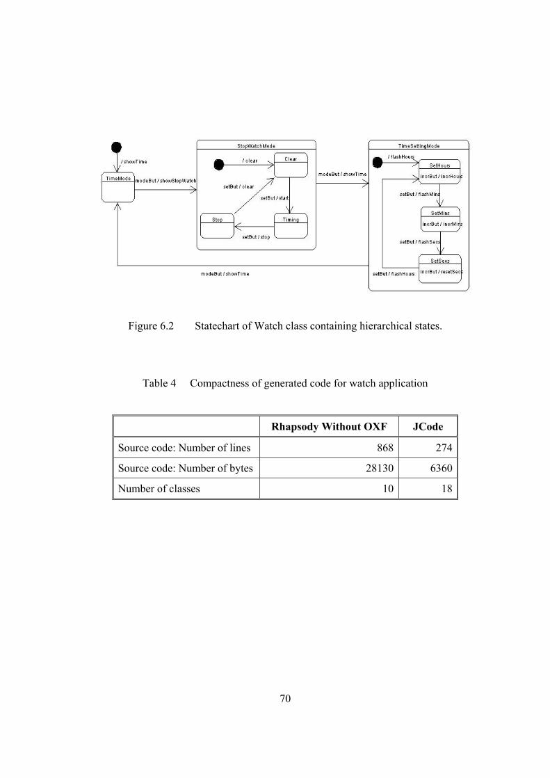
70
Figure 6.2 Statechart of Watch class containing hierarchical states.
Table 4 Compactness of generated code for watch application
Rhapsody Without OXF JCode
Source code: Number of lines 868 274
Source code: Number of bytes 28130 6360
Number of classes 10 18
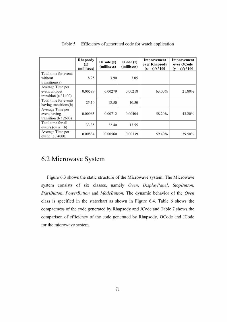
71
Table 5 Efficiency of generated code for watch application
Rhapsody
(x) (millisecs)
OCode (y) (millisecs)
JCode (z) (millisecs)
Improvement over Rhapsody
(x – z)/x*100
Improvementover OCode(y – z)/y*100
Total time for events without transitions(a)
8.25 3.90 3.05
Average Time per event without transition (a / 1400)
0.00589 0.00279 0.00218 63.00% 21.80%
Total time for events having transitions(b) 25.10 18.50 10.50
Average Time per event having transition (b / 2600)
0.00965 0.00712 0.00404 58.20% 43.20%
Total time for all events (c= a + b) 33.35 22.40 13.55
Average Time per event (c / 4000) 0.00834 0.00560 0.00339 59.40% 39.50%
6.2 Microwave System
Figure 6.3 shows the static structure of the Microwave system. The Microwave
system consists of six classes, namely Oven, DisplayPanel, StopButton,
StartButton, PowerButton and ModeButton. The dynamic behavior of the Oven
class is specified in the statechart as shown in Figure 6.4. Table 6 shows the
compactness of the code generated by Rhapsody and JCode and Table 7 shows the
comparison of efficiency of the code generated by Rhapsody, OCode and JCode
for the microwave system.

72
Figure 6.3 Class diagram for the microwave system
Figure 6.4 Statechart of Oven class containing concurrent states.

73
Table 6 Compactness of generated code for microwave system
Rhapsody Without OXF JCode
Source code: Number of lines 1236 347
Source code: Number of bytes 40050 7890
Number of classes 14 22
Table 7 Efficiency of generated code for microwave system
Rhapsody
(x) (millisecs)
OCode (y) (millisecs)
JCode (z) (millisecs)
Improvement over Rhapsody
(x – z)/x*100
Improvementover OCode(y – z)/y*100
Total time for events without transitions(a)
5.80 3.75 2.95
Average Time per event without transition (a / 1330)
0.00436 0.00282 0.00222 49.10% 21.30%
Total time for events having transitions(b) 26.05 28.30 10.35
Average Time per event having transition (b / 2670)
0.00976 0.01060 0.00388 60.30% 63.40%
Total time for all events (c= a + b) 31.85 32.05 13.30
Average Time per event (c / 4000) 0.00796 0.00801 0.00333 58.20% 58.50%
6.3 Dishwasher System
We have generated the code for the Dishwasher system of Figure 3.1 and
compared the code generated by Rhapsody and JCode. Table 8 shows the
compactness of code generated by Rhapsody and JCode. Table 9 shows the
comparison of efficiency of the code generated by Rhapsody, OCode and JCode.
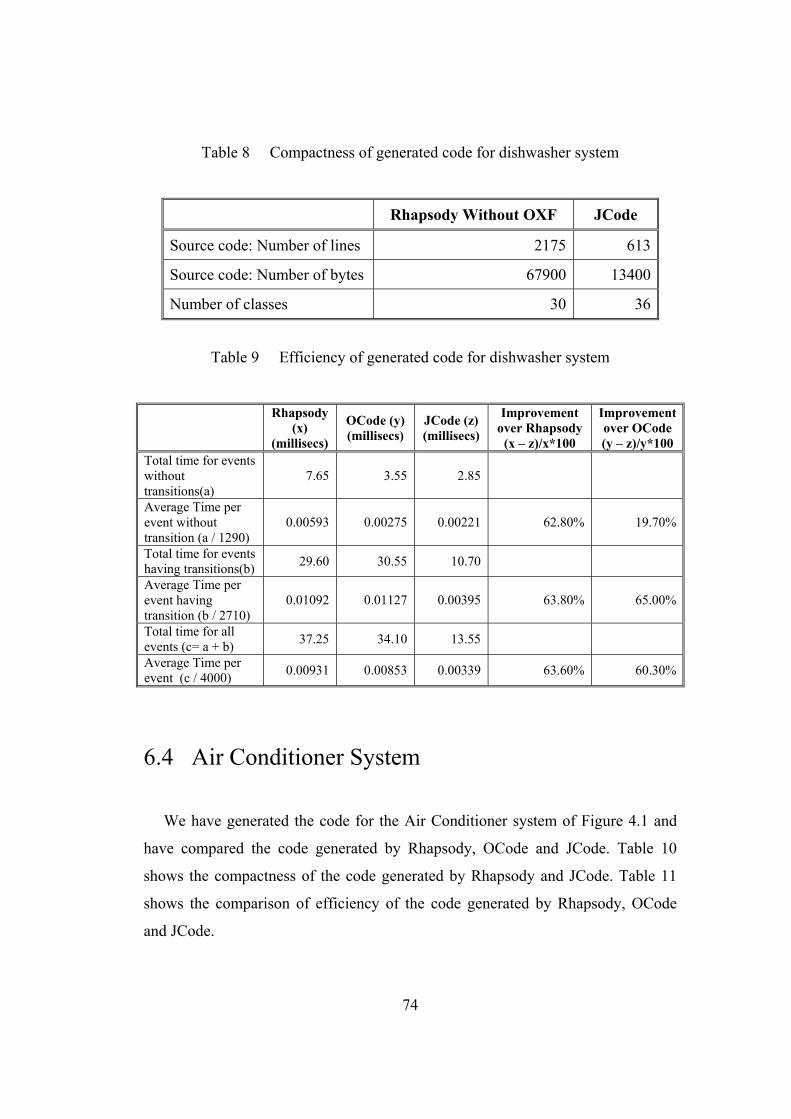
74
Table 8 Compactness of generated code for dishwasher system
Rhapsody Without OXF JCode
Source code: Number of lines 2175 613
Source code: Number of bytes 67900 13400
Number of classes 30 36
Table 9 Efficiency of generated code for dishwasher system
Rhapsody
(x) (millisecs)
OCode (y) (millisecs)
JCode (z) (millisecs)
Improvement over Rhapsody
(x – z)/x*100
Improvementover OCode(y – z)/y*100
Total time for events without transitions(a)
7.65 3.55 2.85
Average Time per event without transition (a / 1290)
0.00593 0.00275 0.00221 62.80% 19.70%
Total time for events having transitions(b) 29.60 30.55 10.70
Average Time per event having transition (b / 2710)
0.01092 0.01127 0.00395 63.80% 65.00%
Total time for all events (c= a + b) 37.25 34.10 13.55
Average Time per event (c / 4000) 0.00931 0.00853 0.00339 63.60% 60.30%
6.4 Air Conditioner System
We have generated the code for the Air Conditioner system of Figure 4.1 and
have compared the code generated by Rhapsody, OCode and JCode. Table 10
shows the compactness of the code generated by Rhapsody and JCode. Table 11
shows the comparison of efficiency of the code generated by Rhapsody, OCode
and JCode.
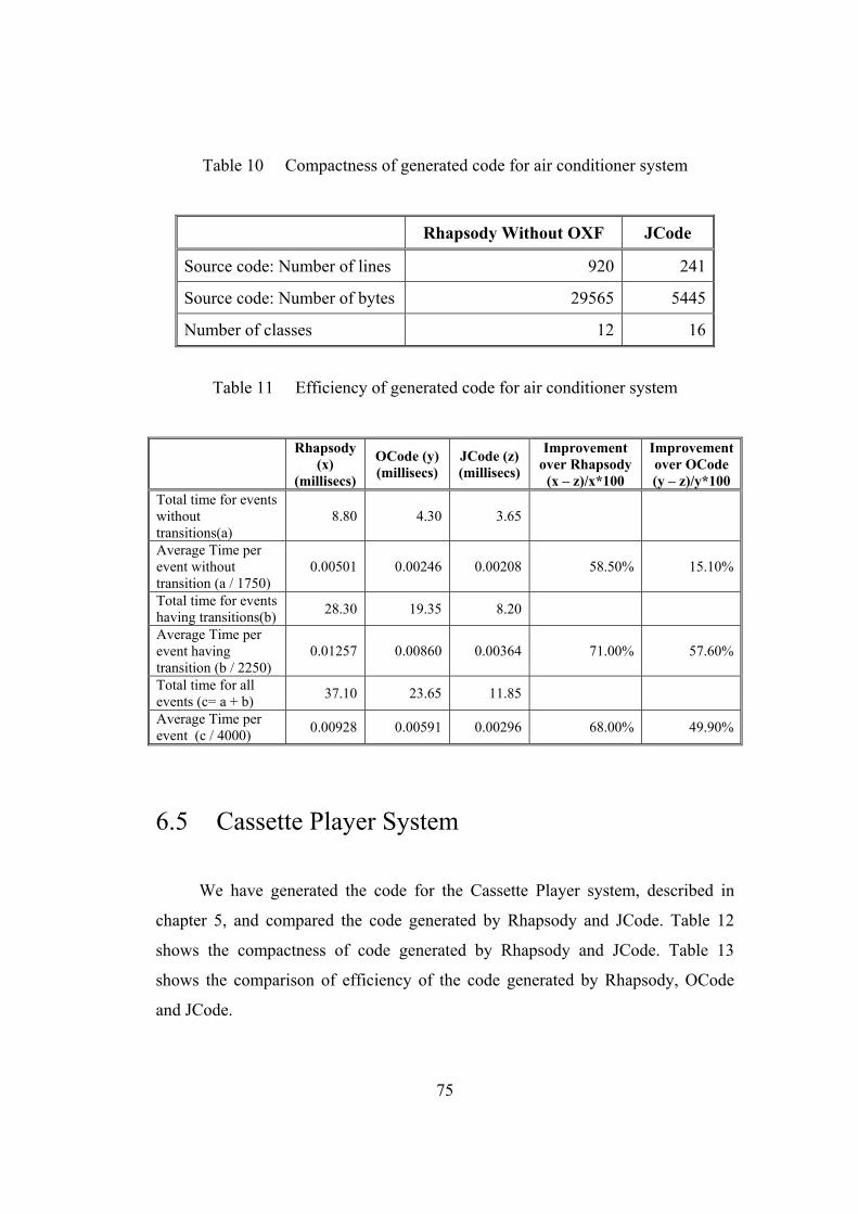
75
Table 10 Compactness of generated code for air conditioner system
Rhapsody Without OXF JCode
Source code: Number of lines 920 241
Source code: Number of bytes 29565 5445
Number of classes 12 16
Table 11 Efficiency of generated code for air conditioner system
Rhapsody
(x) (millisecs)
OCode (y) (millisecs)
JCode (z) (millisecs)
Improvement over Rhapsody
(x – z)/x*100
Improvementover OCode(y – z)/y*100
Total time for events without transitions(a)
8.80 4.30 3.65
Average Time per event without transition (a / 1750)
0.00501 0.00246 0.00208 58.50% 15.10%
Total time for events having transitions(b) 28.30 19.35 8.20
Average Time per event having transition (b / 2250)
0.01257 0.00860 0.00364 71.00% 57.60%
Total time for all events (c= a + b) 37.10 23.65 11.85
Average Time per event (c / 4000) 0.00928 0.00591 0.00296 68.00% 49.90%
6.5 Cassette Player System
We have generated the code for the Cassette Player system, described in
chapter 5, and compared the code generated by Rhapsody and JCode. Table 12
shows the compactness of code generated by Rhapsody and JCode. Table 13
shows the comparison of efficiency of the code generated by Rhapsody, OCode
and JCode.

76
Table 12 Compactness of generated code for cassette player system
Rhapsody Without OXF JCode
Source code: Number of lines 550 178
Source code: Number of bytes 13960 4031
Number of classes 6 12
Table 13 Efficiency of generated code for cassette player system
Rhapsody
(x) (millisecs)
OCode (y) (millisecs)
JCode (z) (millisecs)
Improvement over Rhapsody
(x – z)/x*100
Improvementover OCode(y – z)/y*100
Total time for events without transitions(a)
11.05 5.05 3.80
Average Time per event without transition (a / 1919)
0.00576 0.00263 0.00198 65.60% 24.80%
Total time for events having transitions(b) 20.85 12.90 7.95
Average Time per event having transition (b / 2081)
0.00999 0.00620 0.00382 61.80% 38.40%
Total time for all events (c= a + b) 31.90 17.95 11.75
Average Time per event (c / 4000) 0.00798 0.00448 0.00294 63.20% 34.50%
6.6 Test Device Application
We have generated the code for the Test Device application described in
chapter 5, and compared the code generated by Rhapsody and JCode. Table 14
shows the compactness of code generated by Rhapsody and JCode. Table 15
shows the comparison of efficiency of the code generated by Rhapsody, OCode
and JCode.
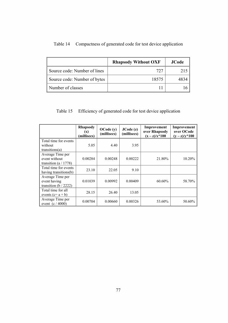
77
Table 14 Compactness of generated code for test device application
Rhapsody Without OXF JCode
Source code: Number of lines 727 215
Source code: Number of bytes 18575 4834
Number of classes 11 16
Table 15 Efficiency of generated code for test device application
Rhapsody
(x) (millisecs)
OCode (y) (millisecs)
JCode (z) (millisecs)
Improvement over Rhapsody
(x – z)/x*100
Improvementover OCode(y – z)/y*100
Total time for events without transitions(a)
5.05 4.40 3.95
Average Time per event without transition (a / 1778)
0.00284 0.00248 0.00222 21.80% 10.20%
Total time for events having transitions(b) 23.10 22.05 9.10
Average Time per event having transition (b / 2222)
0.01039 0.00992 0.00409 60.60% 58.70%
Total time for all events (c= a + b) 28.15 26.40 13.05
Average Time per event (c / 4000) 0.00704 0.00660 0.00326 53.60% 50.60%
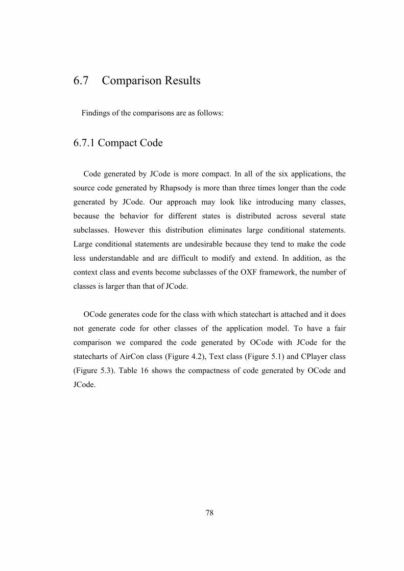
78
6.7 Comparison Results
Findings of the comparisons are as follows:
6.7.1 Compact Code
Code generated by JCode is more compact. In all of the six applications, the
source code generated by Rhapsody is more than three times longer than the code
generated by JCode. Our approach may look like introducing many classes,
because the behavior for different states is distributed across several state
subclasses. However this distribution eliminates large conditional statements.
Large conditional statements are undesirable because they tend to make the code
less understandable and are difficult to modify and extend. In addition, as the
context class and events become subclasses of the OXF framework, the number of
classes is larger than that of JCode.
OCode generates code for the class with which statechart is attached and it does
not generate code for other classes of the application model. To have a fair
comparison we compared the code generated by OCode with JCode for the
statecharts of AirCon class (Figure 4.2), Text class (Figure 5.1) and CPlayer class
(Figure 5.3). Table 16 shows the compactness of code generated by OCode and
JCode.
79
Table 16 Compactness of code generated by OCode and JCode
OCode JCode
Source code: Number of lines 150 136
CPlayer Class Source code: Number of bytes 3964 3182
Number of classes 6 7
Source code: Number of lines 208 178
Test Class Source code: Number of bytes 5065 4021
Number of classes 11 11
Source code: Number of lines 231 192
AirCon Class Source code: Number of bytes 5614 4268
Number of classes 10 10
The results show that the code generated by JCode is about 10% more compact
than OCode. OCode generates almost the same number of classes.
Rhapsody uses data values to represent states. Events are represented as classes
and are derived from the framework class RiJEvent. All the behavior of the context
class is put into one class. The code generator automatically derives model classes
from the framework classes based on the application classes. That is why
Rhapsody has a smaller number of classes than JCode. The transition searching is
performed by switch statement. Each event handler method contains the switch
statement and checks each state of the statechart to get the current active state.
Each state has its own event processing method. The entry/exit actions are
implemented as methods and for every state three different versions of entry
actions and two different versions of exit actions are generated. Even if the entry or
exit actions are not defined for a state, the empty method bodies are generated. As
events are represented as classes, a separate class containing the event definition is
80
generated for each event of the statechart. That is why the code generated by
Rhapsody is more than three times longer than the code generated by JCode.
OCode as well as JCode distribute the behavior among context and state classes.
The state classes contain implementation methods only for their specific events and
entry/exit actions. If there are no specific entry/exit actions or no outgoing
transitions for a state then the state classes execute the inherited methods from the
abstract state class. In OCode the state hierarchy is represented by inheritance and
concurrency by composite object, while JCode implements state hierarchy and
concurrency by object composition and delegation. That is why the number of
classes is almost the same in OCode and JCode. OCode uses temporary objects so
on each transition a new state object is created. JCode uses more persistent and
permanent objects and state objects are created once in the constructor of context
class. In OCode the setting of next state is the responsibility of the current state, so
the event method of the state object contains the code for setting the new state and
also calling the entry method of the new state. In JCode, the setting of next state is
the responsibility of the context class and a method setState() is defined in the
context class for this purpose. The current state after executing its exit action calls
the setState() method. The setState() method sets the new state and also executes
the entry action of the new state. That is why the code generated by JCode is about
10% more compact than OCode and more than three times more compact than
Rhapsody.
6.7.2 Efficient Code
The results of the experiment show that in all of the six applications, the code
generated by JCode is about 60% more efficient than Rhapsody and about 50%
more efficient than OCode.
81
In Rhapsody, events are represented as objects. The client object calls the gen()
method of the context object, which creates the event object and then consumes the
event. Various framework classes are involved in the invocation of the event
processing mechanism. The transition searching is performed using a switch
statement. If there is a transition on the event then the corresponding event
handling method is called, otherwise it returns a false value and the event is
ignored. On transition, apart from setting the new state, various methods are
executed to perform the two exit actions and three entry action methods defined for
the corresponding state. When summed up, all this takes a considerable amount of
time to process an event.
OCode uses temporary state objects and on every transition a new state object is
created which implements the behavior specific to the new state. The state
reference is updated with the new target state object. The state object is defined as
a class variable rather than the instance variable. Similarly, all the action methods
of the context class are also defined as class methods. On the occurrence of an
event, the context class delegates it to the helper object. There is no conditional
structure in the code and the transition searching is performed using polymorphism.
If there is no transition, then only the empty event method is executed by the state
object, which it inherits from the abstract state class and nothing more happens.
JCode has used more persistent and permanent state objects and all the state
objects are created only once in the constructor of the context class. The
collaborator object is defined as an instance variable. All the action methods are
defined as instance methods. On the occurrence of an event, the context class
delegates it to the collaborator object. On transition, the event method defined in
the concrete state class is executed. The exit action of the current state is called,
followed by calling the setState() method of the context to set the collaborator
object with the reference of the new state and no new object is created. The
composite state class handles the event targeted to the composite state or its
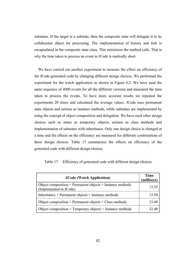
82
substates. If the target is a substate, then the composite state will delegate it to its
collaborator object for processing. The implementation of history and fork is
encapsulated in the composite state class. This minimizes the method calls. That is
why the time taken to process an event in JCode is markedly short.
We have carried out another experiment to measure the effect on efficiency of
the JCode generated code by changing different design choices. We performed the
experiment for the watch application as shown in Figure 6.2. We have used the
same sequence of 4000 events for all the different versions and measured the time
taken to process the events. To have more accurate results we repeated the
experiments 20 times and calculated the average values. JCode uses permanent
state objects and actions as instance methods, while substates are implemented by
using the concept of object composition and delegation. We have used other design
choices such as states as temporary objects, actions as class methods and
implementation of substates with inheritance. Only one design choice is changed at
a time and the effects on the efficiency are measured for different combinations of
these design choices. Table 17 summarizes the effects on efficiency of the
generated code with different design choices.
Table 17 Efficiency of generated code with different design choices
JCode (Watch Application) Time (millisecs)
Object composition + Permanent objects + Instance methods (Implemented in JCode) 13.55
Inheritance + Permanent objects + Instance methods 13.50
Object composition + Permanent objects + Class methods 13.40
Object composition + Temporary objects + Instance methods 32.40
83
The results show that other design choices such as inheritance and class
methods do not have a significant effect on the efficiency of the generated code.
The use of temporary objects has a profound effect on the efficiency and the
performance is degraded significantly. We can conclude that the use of persistent
and permanent objects is the major reason for the JCode generated code to be more
efficient than the code generated by other systems.
We have put all the behavior associated with a particular state into one class.
Because all the state-specific code is contained in a single state class, new states
and events can be added easily by defining new subclasses and operations.
Representing different states as separate objects makes the transitions more explicit
and the code more understandable. JCode also generates appropriate comments
within the code to make the generated code more readable and understandable.
84
Chapter 7
Related Work The most related works are that of Rhapsody [19, 20, 21] and OCode [24, 25].
Rhapsody generates C, C++ and Java code from UML class and statechart
diagrams. OCode generates Java code from OMT dynamic models. As described
earlier, our code is more compact, efficient and readable than that of Rhapsody.
Our code is more efficient than OCode.
7.1 Implementing Class Diagram
In addition to Rhapsody, there are other commercially available CASE tools
that support graphical editors to draw various UML diagrams and generate some of
the implementation code from some of these diagrams. ArgoUML [11], Poseidon
[12], Metamill [13], objectiF [14], MagicDraw [15] and Objecteering [16] allow to
create UML models and generate limited skeleton code from UML class diagrams.
Code generation from only the class diagram generates a limited skeleton code and
is not executable. These tools generate only the header files from the class
diagrams.
85
7.2 Implementing Statechart with Switch Statement In this section we will discuss the approaches for implementing statecharts
which are based on switch statement approach [34] discussed in section 2.1 of
chapter 2.
Metz et al [35] proposed an approach to implement statechart diagrams based
on switch statement [34]. States are represented as constant attributes, events and
actions as methods. All the behavior is put into one class. State transition is
performed using a switch statement. State hierarchy is implemented using flat
states and separate methods are defined to handle the transitions for substates and
history state. Concurrent states are not implemented.
7.3 Implementing Statechart with Design Patterns
Our approach for implementing statecharts has some similarity with State
design pattern [36] but State pattern does not provide any means for implementing
the dynamic parts of the statechart. The State pattern provides a structural
mechanism and the implementation strategy of individual states, state hierarchy
and concurrency is left open. Several other design patterns have been proposed to
implement statechart diagram. These patterns focus on some particular features of
the statechart but none of them have been used in any code generating system.
Since a design pattern specifies a general solution for recurring design problems, it
is not expected to describe the details of the implementation. It provides guidelines
for the implementation but the actual implementation decisions have to be made by
the developer.
Douglass [34] proposed the State Table Pattern to implement the statechart
diagrams. States and transitions are modeled as classes. The context class contains
86
a State Table instance that provides references to concrete state and transition
objects. The state table encapsulates the transition table of size num_states x
num_transitions. The context object sends an external event, encapsulated as a
constant, to the transition class that returns the resulting state. Next, the context
delegates the processing to the event to that state object. The transition table is a
sparse array and has a high initialization overhead as a large table is needed to be
initialized.
Yacoub and Ammar [37] proposed a pattern language of statecharts based on the
concepts of statecharts developed by Harel [4]. Basic Statechart pattern is an
extension to state design pattern [36] to implement guards and entry/exit actions.
Hierarchical Statechart and Orthogonal Statechart are extensions to Basic
Statechart pattern for implementing hierarchical and concurrent substates. History
State pattern is an extension of Hierarchical State pattern for implementing history
state.
Tomura et al. [38, 39] proposed the Statechart design pattern for finite state
machines. The context class has exactly one StateMachine object. The
StateMachine is a class for describing a statechart. The object of this class consists
of two set of states and transitions. The object corresponds to either of a statechart
diagram itself, sequential substate or a concurrent substate. Entry/exit actions,
guards and actions on transitions are all implemented as interfaces. Entry/exit
actions are implemented as methods in the state object and guards and actions are
implemented as methods in the corresponding transition object. The transition is
also represented as an object. On the occurrence of an event, each StateMachine
object automatically updates its current state by referring to its Transition objects
corresponding to the event. Transition searching is performed by a conditional
statement. There is no support for history state and join.

87
Samek [40, 41] proposed two design patterns, Hierarchical State Machine
(HSM) and the Quantum Hierarchical state machine (QHsm), to implement state
hierarchy and transition dynamics. In HSM, states are represented as instances of
the State class, but unlike the state pattern [36], the State class in not intended for
subclassing but rather for inclusion as is. The important attributes of State class are
the event handler (to describe behavior specific to state) and a pointer to superstate
(to define nesting of the state). All states are potentially composite as there is no
distinction between composite states and the leaf states. Messages are represented
as instances of Msg class or its subclasses. All messages carry event type as
attribute. Events are handled by event handlers which are member function of
HSM class. Transition searching is performed using a switch statement inside the
event handler function. Entry/exit actions and default transitions are also
implemented inside the event handler function. The state machine engine generates
and dispatches these events to appropriate handlers upon state transition.
The QHsm is an improved version of HSM. The QHsm class provides
implementation for the event handler function and the function that implements the
state transitions. ConcreteQHsm classes are derived from QHsm class and they
have to implement functions for handling the events in specific states (one function
for each composite and simple state). The dispatcher function inherited from
QHsm is responsible for delegating events from the deepest state in the hierarchy
until it is handled or the top state is reached. Although this pattern provides support
for reflecting the state hierarchy and flexible implementation of transitions, the
action associated to the transition cannot be directly represented. The action has to
be performed before or after entry/exit action. Concurrency and history state are
not supported by both HSM and QHsm.
Pinter and Majzik [42] proposed an extension to QHsm called Extended
Quantum Hierarchical state machine (EQHsm). They proposed support for actions
on transition, concurrency and history state. A pointer to action is passed as a
88
parameter in the transition function. History state is represented as a pointer in the
event method. Concurrency is implemented by multiple communicating state
machines with wrapper states and special events.
Gurp and Bosch [43] presented a design pattern called Finite State Machines
(FSM) framework, which models all the statechart elements as classes. States,
events, actions and transitions are represented as objects. The FSMContext class
holds a reference to the current state and all state-specific data (in a repository).
State is represented by a single class and contains a set of transitions. The
transition object has a reference to the target state and an action object. The
FSMContext responds to events and passes the events on to the current state. The
state object maintains a list of transition-event pairs. When an event is received the
corresponding transition is located and then executed. The transition object
executes the associated action and then sets the target state as the current state in
FSMContext. The structure of the FSMContext object is complex and contains a
large repository of objects. FSM framework generates code only for the finite state
machines and does not implement the hierarchical and concurrent substates. The
context repository does not provide any interface to update the state-specific data
so action classes can make uncontrolled changes to the data.
Köhler et al. [44] presented a tool FUJABA [45] for code generation from UML
class and statecharts. Their approach adapts the idea of array based state table [34]
but uses an object-oriented implementation of the state table. FUJABA uses
objects to represent the states and attributes to hold the entry/exit and action
methods. The state objects are linked via transition objects. Each transition object
has an array of target states. The transition objects have their firing event name.
Additional links and attributes represent the nesting of complex states, history
states etc. Events are implemented as methods. The event methods create an event
object encapsulating the event name and possible parameter values. A library
function is used to interpret the table of the state and to react on events. This
89
function is also responsible for issuing appropriate action methods and switching
to the resulting states. The hierarchical and concurrent states are handled by
flattening the statechart. The table look up is less efficient than a virtual function
call. The transition logic is less explicit and it is difficult to add actions to
accompany the state transitions.
Ran [46] proposed models for object-oriented design of state (MOODS). MOODS
are a family of design patterns that may be used to simplify the design and
implementation of objects with state-dependent behavior. An alternative technique
of selecting the optimal design among different state machine patterns, using
design decision trees (DDT) is proposed. Design decisions are fine-grained
elements of design. States can be represented as classes and events as methods.
The focus is primarily on generic problems such as complex object behavior, event
cause state changes, which are prerequisites to state design pattern [36].
7.4 Other Approaches to Implement Statechart
In this section we will discuss approaches to implement statecharts which are
neither discussed in chapter 2 nor sections 7.2 and 7.3. These are different from the
ones we have discussed so far.
Mellor and Balcer [47] proposed the executable UML (xUML) methodology
which uses a specialized subset of UML notation for software development. The
xUML uses UML class diagram, statechart diagram and action language. An
application-independent software architecture is suggested which defines a set of
design decisions expressed as a set of rules to apply to an application to produce
the implementation of a system [48]. The architecture has a structure similar to
UML metamodel. A StateChart class is defined which holds a representation of
90
statechart. One StateChart object is instantiated for each class that has a statechart.
An abstract base class ActiveInstance is created which captures the data and
behavior common to each object instance of context class. The StateChart class
captures the specification of state behavior while the ActiveInstance captures the
current state of each object instance. These architectural design decisions and the
applications (as stored in metamodel) are combined using a translation template
written in a special-purpose language. The model compilers use these templates to
generate the implementation code.
Shlaer and Mellor [49] proposed an implementation of statecharts which is
based on a linked list of transitions. They use a subset of Harel’s statecharts [4].
UML statechart diagram has extended the Harel’s statechart to make it object-
oriented [1]. States are represented as data values and events as operations in the
context class with which statechart is attached. Transitions are represented as
objects. The Context class maintains an instance of a State Machine. The State
Machine object maintains a linked list of transition objects. Each transition object
knows an event ID, a source state and a target state. A transition object exists for
each combination of events and states, even for those events that are to be ignored.
On the occurrence of event, the context object traverses its list of transitions. The
transition object either returns the next state or informs context to ignore the event.
Actions are not provided for transitions. There is no support for hierarchy,
concurrency and entry/exit actions.
Wasowski [50, 51] presented a hierarchical code generator called SCOPE [52].
SCOPE compiles a sublanguage of statecharts supported by visualSTATE [53] and
produces C language code. The visualSTATE statecharts are a subset of Harel’s
statecharts [4] incorporating most of the original statechart language including
concurrent states, history, internal transitions and other elements. These statecharts
are similar to UML statecharts. SCOPE uses flattening in which hierarchical
statecharts are converted into parallel Mealy machines and then code is generated.
91
SCOPE’s hierarchy tree is represented in integer arrays. State addresses (array
indexes) are used as state identifiers. Transitions are stored in a simple hash table,
with events being hash keys. Each event has a linear list of transitions assigned.
92
Chapter 8
Conclusion
An object-oriented approach has been proposed to convert the UML class and
statechart diagram into implementation code. Our approach generates compact and
efficient executable code for the entire application model. The generated code
contains the structural as well as behavioral code for all the classes of the
application model.
The statechart diagram, which is difficult to implement, can now easily be
implemented by using the collaborator object approach. In our approach, states in
the statechart diagram are represented as classes and transitions as operations
eliminating the need of using large conditional statements. All the behavior related
with a particular state is put into one object and this localizes the state-specific
behavior. Because all state-specific code lives in a state subclass, new states and
transitions can be added easily by defining new subclasses. Our approach
distributes behavior for different states across several state classes. This increases
the number of classes, but such distribution is actually good as introducing
separate objects for different states makes the transitions more explicit. This makes
the components of the statechart diagram explicit and the resulting code easier to
understand and maintain. Our approach implements the statechart semantics as
93
faithfully as possible and ensures that the resultant code is still consistent with the
UML model.
The proposed approach has been implemented in our system, JCode, which
automatically converts the UML class and statechart diagrams specifications into
Java code. The comparison with Rhapsody shows that the code generated by JCode
system is about 60% more efficient and about three times more compact than that
of Rhapsody. Our Code is also about 10% more compact and about 50% more
efficient than that of OCode.
Our approach is an object-oriented approach and in the present study we have
used Java as the target language. However our approach is general so it can be
used to generate the low level code in other object-oriented languages. The code
generation engine has to be tailored to the target language as some of the features
are implemented differently in different object-oriented programming languages.
94
Acknowledgments
First and foremost, I would like to express my heartfelt gratitude to my
supervisor, Professor Jiro Tanaka, for his clear advice, invaluable guidance,
constant support and encouragement during all stages of this study. I was amazed
by both his insight and stamina. His kind gestures will never be forgotten.
I would like to extend my sincere thanks to Dr. Nobuo Ohbo, Dr. Koichi Wada,
Dr. Hiroyuki Kitagawa and Dr. Kazuo Misue of University of Tsukuba for their
invaluable comments and suggestions.
I am also obliged to Ministry of Education, Culture, Sports, Science and
Technology (Monbukagakusho), Japan and Japan Student Services Organization
(JASSO) for providing me financial assistance without which this study would not
have been possible.
I am grateful to Dr. Buntaro Shizuki, Dr. Shin Takahashi and Dr. Motoki Miura,
for their support and timely help. I also owe thanks to several current and former
members of IPLAB members for their support and nice company.
Special thanks to Ms. Simona Vasilache, Ms. Xiaoping Ying and Mr. Xuejun
Liu for their useful discussions, constructive criticism and nice company
throughout my stay in Japan.
My sincere tributes are due to Chairman, Department of Computer Science,
Dean, Faculty of Natural Sciences and the Vice Chancellor, Quaid-i-Azam
University for granting me study leave to accomplish this doctoral program.

95
Special thanks are due to all of my colleagues at Department of Computer Science,
Quaid-i-Azam University for their moral support.
I wish to express my thanks to all my friends in Pakistan and Japan for their
good wishes, encouragement and prayers.
I am highly obliged to my parents, brothers and sisters for their encouragement,
heartfelt support and benevolent prayers. They have been always a source of
inspiration and endless encouragement for me.
This arduous work would not have been accomplished without the help and
support of my wife Fariha and our children, Rameen and Sarmad. I am especially
thankful for their understanding, moral support and love. Without them, I would
never have made it through the doctoral program. They helped me get through the
bad times and enjoy the good times. I dedicate this work to all of them with love
and affection.
Finally, I am thankful to God for having granted me the skills and opportunities
that made this possible.

96
Bibliography [1] Object Management Group (OMG), Unified Modeling Language (UML)
specifications version 1.5, 2003. http://www.omg.org/
[2] G. Booch, J. Rumbaugh, and I. Jacobson, “The Unified Modeling Language:
User Guide”, Massachusetts: Addison-Wesley, 1999.
[3] J. Rumbaugh, I. Jacobson, and G. Booch, “The Unified Modeling Language:
Reference Manual Guide”, Massachusetts: Addison-Wesley, 1999.
[4] D. Harel, “Statecharts: A visual formalism for complex systems”, Science of
Computer Programming, vol. 8, no. 3, pp 231-274, Jun. 1987.
[5] G. Booch, “Object Oriented Design with Applications”, California:
Benjamin/Cummins, 1991.
[6] J. Rumbaugh, M. Blaha, W. Premerlani, F. Eddy and W. Lorenson, “Object-
Oriented Modeling and Design”, New Jersey: Prentice-Hall, 1991.
[7] I. Jacobson, “Object-Oriented Software Engineering: A Use Case Driven
Approach”, Massachusetts: Addison-Wesley, 1992.
[8] International Business Machines (IBM) Corporation, Rational Unified
Process, 2003, http://www-306.ibm.com/software/awdtools/rup/
[9] P. Coad and E. Yourdan, “Object-Oriented Analysis”, New Jersey: Prentice
Hall, 1991.
[10] Philippe Desfray, “Object Engineering: The Fourth Dimension”,
Massachusetts: Addison-Wesley, 1994.
[11] Tigris.org, ArgoUML, http://argouml.tigris.org
[12] Gentleware AG, Poseidon for UML, http://www.gentleware.com
[13] Metamill Software, Metamill, http://www.metamill.com
[14] MicroTOOL, objectiF, http://www.microtool.de/objectif/
[15] No Magic Inc. MagicDraw, http://www.magicdraw.com
[16] Objecteering Software, Objecteering/UML, http://www.objecteering.com
97
[17] A. S. Ran, “Modeling States as Classes”, in Proc. Technology of Object-
Oriented Languages and Systems Conference, 1994.
[18] A. Sane, and R. Campbell, “Object-Oriented State Machines: Subclassing,
Composition, Delegation, and Genericity”, ACM SIGPLAN Notices,
OOPSLA'95, vol.30, Austin, Texas, USA, 1995, pp. 17-32.
[19] I-Logix Inc., Rhapsody, http://www.ilogix.com.
[20] D. Harel, and E. Grey, “Executable Object Modeling with Statecharts”, in
Proc. of 18th International Conf. on Software Engineering, IEEE, March
1996, pp. 246-257.
[21] D. Harel, and E. Grey, “Executable Object Modeling with Statecharts”,
Computer, vol. 30, no. 7, 1997, pp. 31-42.
[22] D. Harel, and A. Namaad, “The STATEMATE Semantics of Statecharts”,
ACM Transactions on Software Engineering and Methodology, vol. 5, no. 4,
1996, pp. 293-333.
[23] J. Ali, and J. Tanaka, “Converting Statecharts into Java Code”, in Proc.
Fourth World Conf. on Integrated Design and Process Technology
(IDPT’99), Dallas, Texas, USA, 2000 (CD-ROM).
[24] J. Ali, and J. Tanaka, “An Object Oriented Approach to Generate Executable
Code from OMT-Based Dynamic Model”, Journal of Integrated Design and
Process Science, vol. 2, no. 4 1998, pp. 65-77.
[25] J. Ali, and J. Tanaka, “Implementing the Dynamic Behavior Represented as
Multiple State Diagrams and Activity Diagrams”, Journal of Computer
Science & Information Management (JCSIM), vol. 2, no. 1, 2001, pp. 24-34.
[26] I. A. Niaz and J. Tanaka, “Code Generation from UML Statecharts”, in Proc.
7th IASTED International Conf. on Software Engineering and Application
(SEA 2003), Marina Del Rey, USA, Nov. 2003, pp. 315-321.
[27] I. A. Niaz and J. Tanaka, “Mapping UML Statecharts to Java Code”, in Proc.
IASTED International Conf. on Software Engineering (SE 2004), Innsbruck,
Austria, Feb. 2004, pp. 111-116.
98
[28] I. A. Niaz and J. Tanaka, “An Object-Oriented Approach To Generate Java
Code From UML Statecharts”, International Journal of Computer &
Information Science, vol. 6, no. 2, 2005 (accepted).
[29] M. Harada, T. Fujisawa, M. Teradaira, K. Yamamoto, and S. Hamada,
“Refinement of Dynamic Modeling of Some Automatic Layouting of Object
Oriented Design Schema and Reverse Engineering of Design Schema from
C++ Program”, in IPSJ Object-Oriented Symposium, Tokyo, Japan, 1996, pp
111-118.
[30] Sun Microsystems Inc., Java Technology, http://java.sun.com
[31] J. Rumbaugh, “OMT: The Object Model”, Journal of Object-Oriented
Programming, vol. 7, no. 8, 1995, pp. 21-27.
[32] J. Rumbaugh, “OMT: The Dynamic Model”, Journal of Object-Oriented
Programming, vol. 7, no. 9, 1995, pp. 6-12.
[33] J. Rumbaugh, “OMT: The Development Process”, Journal of Object-
Oriented Programming, vol. 7, no. 12, 1995, pp. 8-16.
[34] B. P. Douglass, “Real Time UML – Developing Efficient Objects for
Embedded Systems”, Massachusetts: Addison-Wesley, 1998.
[35] P. Metz, J. O’Brien and W. Weber, “Code Generation Concepts for
Statechart Diagrams of the UML v1.1”, Object Technology Group (OTG)
Conference, Vienna, Austria, June 1999.
[36] E. Gamma, R. Helm, R. Johnson, and J. Vlissides, “Design Patterns:
Elements of Reusable Object-Oriented Software”, Massachusetts: Addison-
Wesley, 1995.
[37] S. M. Yacoub and H. H. Ammar, “A Pattern Language of Statecharts” in
Proc. Fifth Annual Conf. on the Pattern Languages of Program (PLoP 98),
Monticello, IL, USA, 1998, TR#WUCS-98-29.
[38] T. Tomura, S. Kanai, K. Uehiro and S. Yamamoto, “Developing Simulation
Models of Open Distributed Control Systems by Using Object-Oriented
Structural and Behavioral Patterns”, in Proc. 4th IEEE International
99
Symposium on Object-Oriented Real-Time Distributed Computing (ISORC
2001), Magdeburg, Germany, 2001, pp. 428-437.
[39] T. Tomura, S. Kanai, K. Uehiro and S. Yamamoto, “Object-Oriented Design
Pattern Approach for Modeling and Simulating Open Distributed Control
System”, in Proc. IEEE International Conf. on Robotics and Automation
(ICRA 2001), Seoul, Korea, 2001, pp. 211-216.
[40] M. Samek and P. Montgomery, “State-Oriented Programming”, Embedded
Systems Programming, vol. 13, no. 8, 2000, pp 22-43.
[41] M. Samek “Practical Statecharts in C/C++”, Gilroy: CMP Books, 2002
[42] G. Pinter and I. Majzik, “Program Code Generation Based On UML
Statechart Models”, Periodica Polytechnica, vol. 47, no. 3, 2003, pp 187-204.
[43] J. V. Gurp and J. Bosch, “On the Implementation of Finite State Machines”,
in Proc. IASTED International Conf. on Software Engineering and
Applications, (SEA’99), Scottsdale, AZ, USA, 1999, pp. 172-178.
[44] H. J. Köhler, U. Nickel, J. Niere, and A. Zündorf, “Integrating UML
Diagrams for Production Control Systems”, in Proc. 22nd International Conf.
on Software Engineering (ICSE 2000), Limerick, Ireland, 2000, pp. 241-251.
[45] Fujaba Case Tool, http://www.fujaba.de/
[46] A. Ran, “MOODS: Models for Object-Oriented Design of State”, in Proc.
Conf. on the Pattern Languages of Program (PLoP 95), 1995.
[47] S. J. Mellor and M. J. Balcer, “Executable UML: A Foundation for Model-
Driven Architecture”, Massachusetts: Addison-Wesley, 2002.
[48] S. J. Mellor, “Automatic Code Generation from UML Models”, Journal of
C++ Report, June 1999.
[49] S. Shlaer and S. J. Mellor, “Object Lifecycles – Modeling The World in
States”, Massachusetts: Addison-Wesley, 1992.
[50] A. Wasowski, “On Efficient Program Synthesis from Statecharts”, in Proc.
ACM SIGPLAN Conf. of Languages, Compilers, and Tools for Embedded
Systems (LCTES’03), San Diego, USA, June 2003, pp. 163-170.
100
[51] A. Wasowski, “Flattening Statecharts without Explosions”, in Proc. ACM
SIGPLAN Conf. of Languages, Compilers, and Tools for Embedded Systems
(LCTES’04), Washington DC., USA, June 2004, pp. 257-266.
[52] SCOPE: A statechart compiler, http://www.mini.pw.edu.pl/~wasowski/scope.
[53] IAR Systems, visualSTATE Case Tool, http://www.iar.com/Products/VS/
101
Author Publications List [1] I. A. Niaz and J. Tanaka, “Code Generation from UML Statecharts”, in Proc.
7th IASTED International Conf. on Software Engineering and Application
(SEA 2003), Marina Del Rey, USA, Nov. 2003, pp. 315-321.
[2] I. A. Niaz and J. Tanaka, “Mapping UML Statecharts to Java Code”, in Proc.
IASTED International Conf. on Software Engineering (SE 2004), Innsbruck,
Austria, Feb. 2004, pp. 111-116.
[3] I. A. Niaz and J. Tanaka, “An Object-Oriented Approach To Generate Java
Code From UML Statecharts”, International Journal of Computer &
Information Science, vol. 6, no. 2, 2005 (accepted).