automotive thermoelectric generator (teg) controls · pdf fileautomotive thermoelectric...
TRANSCRIPT
Future Tech
# 1
Automotive Thermoelectric Generator (TEG) Controls
Francis Stabler General Motors & Future Tech LLC March 2012 DOE Thermoelectric Workshop Baltimore, MD
Future Tech
# 2
Automotive TEG Systems Require Controls to Function
• Thermoelectric materials and modules have been a major focus for automotive applications; however, controls will be required for successful TEG application.
• The controls consist of sensors, actuators, and control logic.
• The specific control components are primarily dependent on the TEG design for a given application.
• This talk will focus primarily the functions needed, not the specific sensors and actuators
Future Tech
# 3
Some of the control functions needed are the following:
• TEG heat exchanger bypass • Coolant pump control • Coolant flow controls • Generator control • DC/DC converter control • Others?
Future Tech
# 4
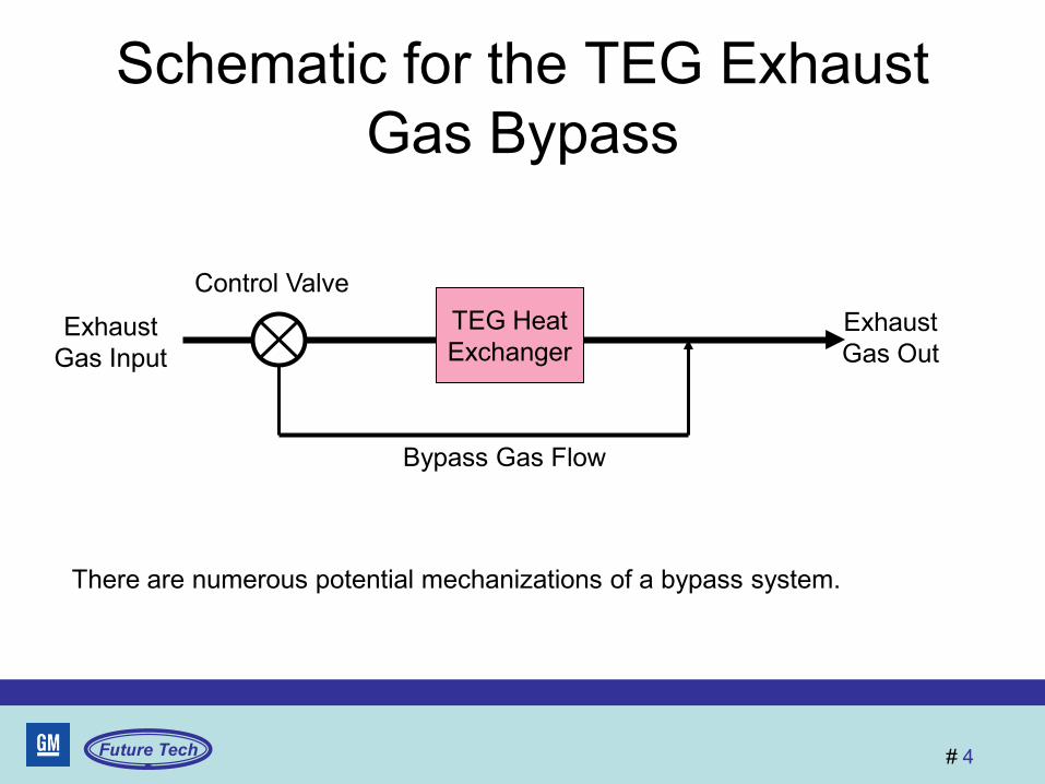
Schematic for the TEG Exhaust Gas Bypass
TEG Heat Exchanger
Control Valve
Exhaust Gas Input
Exhaust Gas Out
Bypass Gas Flow
There are numerous potential mechanizations of a bypass system.
Future Tech
# 5
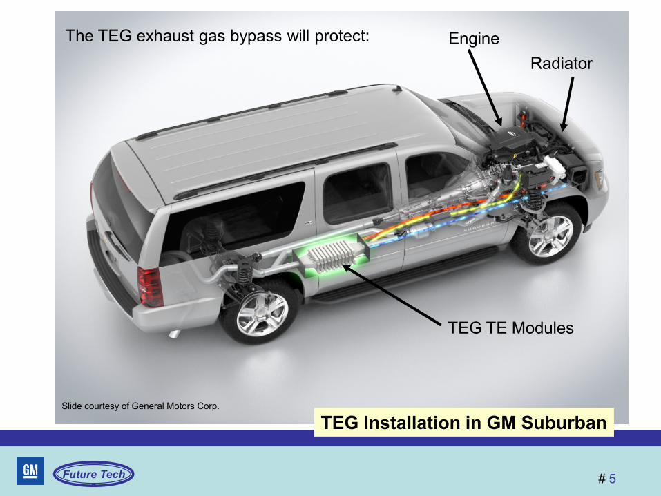
TEG Installation in GM Suburban Slide courtesy of General Motors Corp.
The TEG exhaust gas bypass will protect: Engine Radiator
TEG TE Modules
Future Tech
# 6
The exhaust bypass protects TE modules from excessive temperature
• Most TE material being considered for automotive TEG use can be damaged by worst case exhaust gas temperatures – Worst case temperature is a short term event
• Bypass would be activated by input from a temperature sensor in the TEG
Future Tech
# 7
The exhaust bypass can protect the engine from excessive backpressure
• Excessive exhaust backpressure will reduce the engine power output and reduce fuel efficiency – The bypass should be activated when high flow rates
are expected or measured • Backpressure limit is a function of the specific engine and
exhaust system with the heat exchanger as the restrictor.
– Rapid throttle opening is an advance indication of high exhaust flow
– A sensor could measure exhaust pressure, but more likely the bypass logic would use a calculated flow value from the engine controller
Future Tech
# 8
The exhaust bypass will protect the TEG system radiator
• This function is needed for a TEG that uses either the vehicle radiator or a separate radiator – The vehicle has excess radiator capacity under most
conditions, but added TEG heat can cause it to overheat at times
– A radiator designed for worst case temperatures, including the TEG, is not feasible
• The bypass will reduce TEG heat until the radiator can manage the input heat – Radiator output temperature sensor needed – Will reduce TEG power out for a short time
Future Tech
# 9
TEG coolant pump control
• A variable speed electric pump is needed to optimize power usage and coolant flow
• Variable speed to aid engine warm-up (more discussion in coolant flow controls)
• Uses a temperature sensor in the output of the TEG coolant flow as a logic input
Future Tech
# 10
Coolant flow controls (optional) • The TEG heat exchanger can be used to provide
warm coolant for rapid engine warm-up – Increase fuel economy – Improved passenger comfort
• Logic can use the engine coolant temperature sensor as input
• For this function, valves route coolant from engine to TEG and back to engine, bypassing the radiator during the warm-up period
• Pump flow rate controlled for optimum warming – Some TEG efficiency loss during engine warm-up
Future Tech
# 11
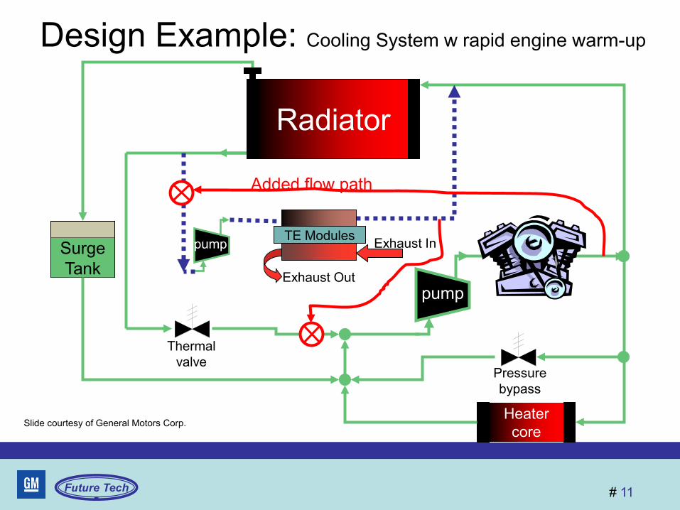
Design Example: Cooling System w rapid engine warm-up
Surge Tank
Heater core
pump
Pressure bypass
Thermal valve
pump
pump TE Modules Exhaust In
Exhaust Out
Radiator
Slide courtesy of General Motors Corp.
Added flow path
Future Tech
# 12
Generator control - optional
• Needed to optimize the fuel economy provided by the TEG when the electrical loads are light. – Light loads = less than average TEG output
• When the ambient temperature allows easy charging of the battery (neither too high or too low for specific battery chemistry), keep the generator off until the TEG output is functioning or additional power is required.
• Over-ride if the battery state of charge is below a set value.
Future Tech
# 13
DC/DC Converter Controls
• Used to match the TEG voltage output to the battery (temperature sensitive for charging) and to the generator output.
• Interface issues, such as voltage mismatch, impedance mismatch, or over voltage charging, will reduce the efficiency of the TEG system (lower impact on fuel economy)
Future Tech
# 14
Where should the TEG control logic reside?
• Stand-alone electronic control unit – Easier to implement, very desirable if optional – Serial data interface with engine controller
• Integrated into the engine control unit – Less expensive if standard equipment – Easier to use engine sensors and data
• Integrated into the generator controls – Provides a single power control – Very unlikely choice
Future Tech
# 15
Summary
• TE modules remain the most important part of automotive TEG design
• TEG application will not take place unless a good control system is developed
• The control system can make the difference between a barely functional TEG and an efficient, cost effective TEG
Future Tech
# 16
Acknowledgements
• US Department of Energy and John Fairbanks for his leadership in thermoelectric technology application
• General Motors and Dr Greg Meisner
Thank You