autonomous formation flying for the prisma mission · smaller target satellite. a gps-based...
TRANSCRIPT
Autonomous Formation Flying for the PRISMA Mission
Eberhard Gill,∗ Simone D’Amico,∗ and Oliver Montenbruck∗
DLR, German Aerospace Center, 82234 Wessling, Germany
DOI: 10.2514/1.23015
PRISMA is a technology demonstration mission for satellite formation flying and in-orbit servicing. The space
segment comprises the fully maneuverableMain minisatellite and the smaller Target satellite in a low Earth orbit at
700-km altitude. A key mission objective is to demonstrate onboard, fully autonomous, robust, safe, and precise
formation flying of spacecraft. This is accomplished by spaceborne global positioning system navigation, guidance,
and control functionalities for the maintenance of the relative motion between the two spacecraft. An innovative
estimation approach employs a commonKalman filter for the absolute states ofMain andTarget, which accounts for
the interdependency of absolute and relative navigationwithout the need for an explicit relative state. As a result, the
onboard navigation systemprovides absolute and relative orbit information in real timewith a position accuracy of 2
and 0.1 m, respectively. The formation control achieves accuracies of a few tenths of meters with minimum usage of
thrusters. The guidance and control concept is detailedwith emphasis on a relative eccentricity and inclination vector
separation strategy. The paper derives estimates of the expected relative orbit control performances based upon real-
world simulations using typical global positioning system receiver and propulsion system characteristics.
Nomenclature
a = semi-major axisa = acceleration vectorB = ballistic coefficientCD = drag coefficientc = velocity of lightdD = along-track acceleration due to dragdt = time difference of filter updatesE = transformation matrixe = eccentricitye = eccentricity vectoreN , eR, eT = unit vectors in normal, radial, and tangential
directionsG = measurement partials vectorg = modeled measurementh = numerical integrator step sizeI = ionospheric biasi = inclinationi = inclination vectorJ2 = second-order zonal coefficient of the geopotentialK = Kalman filter gain vectorl = longitudeM = mean anomalyN = integer bias of carrier phaseN = integer bias vectorn = mean motionP = covariance matrixQ = process noise covariance matrixR� = Earth equatorial radiusr = radius vector of the spacecraft�r = acceleration of the spacecraftt = timeu = mean argument of latitude
v = velocity of the spacecraftW = measurement weightx = Kalman filter statez = measurement� = J2 perturbation coefficient� = difference operator�l = relative mean longitude�t = drift time interval�� = attitude control error�� = relative navigation error�e = relative eccentricity vector amplitude�i = relative inclination vector amplitude�t = clock offset�� = relative difference operator, ���� ������ = differential ballistic coefficient� = propulsion system performance� = relative ascending node� = wavelength = Earth’s gravitational coefficient� = pseudorange = process noise� = time scale of process noise� = transition matrix� = carrier phase’ = relative perigee� = right ascension of the ascending node! = argument of perigeer� = double-difference operator
Subscripts
a = accelerationclk = clockD = dragemp = empirical accelerationG = gravityGPS = global positioning systemi = Kalman filter stepM = Main spacecraft of PRISMA formationM = moonN = normalR = radialS = sunSR = solar radiationT = totalT = tangential
Presented as Paper 06-121 at the 16th AAS/AIAASpace FlightMechanicsMeeting, Tampa, FL, 22–26 January 2006; received 6 February 2006;revision received 10 November 2006; accepted for publication 5 February2007. Copyright © 2007 by the American Institute of Aeronautics andAstronautics, Inc. All rights reserved. Copies of this paper may be made forpersonal or internal use, on condition that the copier pay the $10.00 per-copyfee to the Copyright Clearance Center, Inc., 222 Rosewood Drive, Danvers,MA 01923; include the code 0022-4650/07 $10.00 in correspondence withthe CCC.
∗Scientist, German Space Operations Center, Space Flight Technology,currently Chairholder, Space Systems Engineering, Faculty of AerospaceEngineering, Delft University of Technology, Kluyerweg 1, 2629 HS Delft,The Netherlands.
JOURNAL OF SPACECRAFT AND ROCKETS
Vol. 44, No. 3, May–June 2007
671
T = Target spacecraft of PRISMA formationx = x component of the vectory = y component of the vector0 = initial condition� = after measurement update� = before measurement update
Superscripts
C=A = coarse acquisition GPS codeL1 = GPS first fundamental frequencymax = maximum valueN = nominal
Introduction
F ORMATION flying of satellites is a research topic that has led toa variety of ambitious mission proposals in the past [1].
However, actual experience in formation flying is limited in terms ofspecific formation flying technologies and their applications. Apartfrom rendezvous scenarios in the framework ofmannedmissions [2],formation flying in lowEarth orbit (LEO) ismainly restricted to a fewscientific applications and technology demonstrations.
The gravity recovery and climate experiment (GRACE) [3] is aclose LEO formation, in orbit since 2002, that operates at an along-track separation of 220� 50 km at 450-km altitude. However, itslarge control window only requires infrequent orbit maneuvers toadjust the relative orbit, which is manually executed via groundcommands. The formation flying demonstration of the Earth-observing mission EO-1/Landsat in 2001 was conducted at 700-kmaltitude, with an along-track separation of 450� 85 km [4]. Since2006, the CloudSat and Calipso spacecraft fly in formation as part ofthe so-called A-train of satellites, with an along-track separation of112� 19 km [5]. In all of these cases, the large control windowallows sparse maneuvers that can conveniently be executed byground control. On the contrary, the demonstration of the auto-nomous rendezvous technology (DART) mission in 2005 attemptedto rendezvous completely autonomously with, and to perform avariety of maneuvers in close proximity to, the multiple-paths-beyond-line-of-sight communications (MUBLCOM) satellite.However, DART did not meet its main mission objectives andultimately caused a collision with the MUBLCOM spacecraft [6].The Experimental Satellite System-11 (XSS-11) was launched in2005 and demonstrated several rendezvous and proximity operationswith a launch vehicle upper stage. It will demonstrate an increasinglevel of autonomy as the project continues.
In the regime of scientific applications in LEO, formation flying isof major interest for interferometric synthetic aperture radar (SAR)applications [7]. Here, short tomedium separations of spacecraft leadto close formations that require autonomous formation keeping. Anexample of an interferometric SAR formation flyingmission is TSX/TDX [8] (TerraSAR-X/TanDEM-X), recently selected as a newEarth-observation mission within the German national spaceprogram. TSX/TDXwill form a radar interferometer orbiting at 500-km altitude, with typical baselines of about 1 km, and will requiredaily orbit maneuvers implemented via either ground-in-the-loopcontrol with a high level of automation [9] or complete onboardautonomy.
The motivation for this work is the development and demon-stration of innovative global positioning system (GPS) guidance,navigation, and control (GNC) algorithms for fully autonomous,robust, and precise formation flying of future spacecraft. Thedemonstration will be accomplished within the PRISMA mission[10], which is a precursor mission for critical technologies forformation flying and in-orbit servicing. The PRISMA space segmentwill comprise the fully maneuverable Main minisatellite and thesmaller Target satellite. A GPS-based navigation system on Mainwill process local GPS measurements and GPS measurements fromTarget, transmitted to Main by an intersatellite radio link, and willprovide continuous and precise absolute and relative orbitinformation in real time. In addition, PRISMA will conduct the
spaceborne autonomous formation flying experiment (SAFE) withthe objective to demonstrate a fully autonomous, robust, and preciseformation flying of spacecraft. To this end, a fuel-optimizedguidance and control algorithm will provide an accuracy of betterthan 25 m at typical spacecraft distances of 100 to 2000 m, which isrepresentative of future interferometric SAR formation flyingmissions like TSX/TDX. SAFEwill acquire andmaintain robust andsafe close formation flying configurations in complete autonomyover long time intervals (weeks).
In the past, onboard navigation systems for rendezvous andformation flying applied a mixture of absolute and relativenavigation for the filter states and their dynamics [2,11,12]. Arelative GPS navigation implementation [2] for the automatedtransfer vehicle (ATV) applies single-difference pseudoranges toestimate the relative states based on a quasi-circular absolute orbitmodel. In [11], only relative filter states are estimated from double-difference carrier phases, whereas the dynamics are based on thenumerical integration of the absolute orbits. In [12], one filter isimplemented for the absolute navigation based on pseudorange andDoppler measurements, whereas a second filter for relativenavigation assumes a Keplerian motion to process single-differencecarrier-phase data. In the present paper, a unique concept for absoluteand relative navigation is presented that is based on a single commonKalman filter for the absolute states of the two spacecraft and on themodeling of their dynamics. This completely abandons the need forrelative filter states and associated relative dynamics and allows oneto fully exploit the interdependency of absolute and relativedynamics. The filter applies pseudorange data from the twospacecraft for the robust reconstruction of the absolute orbits,whereas a precise and implicit determination of the relative orbit isachieved based upon ambiguity resolution of double-differencecarrier-phase measurements. The concept is robust in terms of theattitude of the spacecraft, because the relative orbit can still bedetermined from pseudoranges, should double-difference carrierphases of commonly viewed GPS satellites not be available. Therelative state vector and its associated covariance matrix may easilybe computed external to the filter without any further limitations andassumptions.
The guidance and control of satellite formations is typicallydescribed using the Cartesian comoving triad defined as part of theHill–Clohessy–Wiltshire (HCW) equations [13,14]. These equa-tions describe the motion of a spacecraft relative to a circularreference orbit under the assumptions that the spacecraft separationsare small with respect to their geocentric distance and that the motionis purely Keplerian. Because the HCW equations neglect thesignificant perturbations of the second-order zonal coefficient J2caused by the Earth’s oblateness, considerable effort was put intotheir extensions to incorporate these contributions [15,16]. In thispaper, guidance and control of satellite formations is insteaddescribed in terms of relative orbital elements, which simplifies theformation flying design and gives immediate insight into thegeometry of the formation [9]. In particular, it separates the relativeeccentricity/inclination vectors through the proper configuration ofthe two spacecraft in radial and cross-track direction. This allowspassively stable formation flying configurations and avoids collisionhazard from along-track position uncertainties. Furthermore, short-and long-term and secular perturbations due to J2 may easily beincorporated into the method. This technique has its roots in thecolocation of geostationary satellites [17] and was successfullyadopted for the first time in LEO to safely switch the satellites of theGRACE formation [18]. In this paper, the method is applied, for thefirst time, to a long-term simulation of autonomous formation controlin the presence of realistic sensors and actuators.
This paper introduces the PRISMA mission [10], addressing itsobjectives, orbit characteristics, and spacecraft design; emphasis isgiven to a description of the selected GPS receiver and thrustercharacteristics. Furthermore, the concept for data handling andonboard software development is described, supplemented by apresentation of the architecture of the GPS-based onboard GNCsoftware. The second part of the paper provides a description of theGPS-based GNC algorithms. Here, the measurement and dynamical
672 GILL, D’AMICO, AND MONTENBRUCK
models are detailed and the applied filter concept is specified. TheSAFE formation control design describes the relative motion of theparticipating satellites in terms of relative orbital elements. Themodel accounts for the second-order zonal coefficient J2 and makesuse of the theories of Brouwer [19] and Lyddane [20] for thecomputation of mean relative orbital elements. A deterministicimpulsive orbit control strategy is shown to be a straightforwardapplication of the Gauss variational equations [21] in combinationwith the adopted relative motion model. Impulsive maneuvers areeasily planned to counteract non-Keplerian orbital perturbations tomaintain and/or reconfigure the formation. Finally, the paperpresents simulation results of the relative orbit guidance and controllaws in the presence of real-world dynamics, including the modelingof sensors and actuators.
PRISMA Mission
Mission Description
The mission objectives of PRISMA may be divided into thevalidation of sensor and actuator technologies related to formationflying and the demonstration of experiments for formation flying andrendezvous. Key sensor and actuator components [10] comprise aGPS receiver system, two vision-based sensors, two formationflyingradio frequency sensors, and a high-performance green propellantsystem. These will support and enable the demonstration ofautonomous spacecraft formation flying, homing, and rendezvousscenarios, as well as close-range proximity operations.
Themission schedule foresees a launch of the two spacecraft in thesecond half of 2008. Both Main and Target will be injected by aDnepr launcher into a sun-synchronous orbit at 700-km altitude and98.2-deg inclination. A dusk–dawn orbit with a 6 or 18 h nominallocal time at the ascending node (LTAN) is targeted. Maximumeclipse times of 23 min may occur for injections within�1 h off thenominal LTAN, depending on the sun’s declination.
Following a separation from the launcher, the two spacecraft willstay in a clamped configuration for initial system checkout andpreliminary verification. Once the spacecraft are separated from eachother, various experiment sets for formation flying and in-orbitservicing will be conducted within a minimum targeted missionlifetime of eight months.
Spacecraft operations will be performed remotely from Solna,near Stockholm, making use of the European Space and SoundingRocket Range (Esrange) ground station in northern Sweden. The S-band ground–space link toMain supports commandingwith a bit rateof 4 kbps and telemetry with up to 1 Mbps. In contrast, communi-cation with the Target spacecraft is only provided through Main
acting as a relay and making use of a Main–Target intersatellite link(ISL) in the ultrahigh-frequency (UHF) band with a data rate of19.2 kbps.
Space Segment
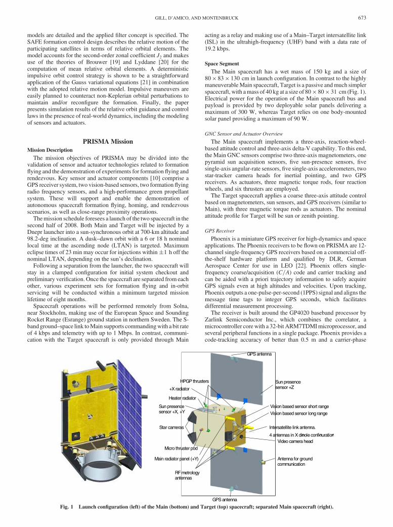
The Main spacecraft has a wet mass of 150 kg and a size of80 � 83 � 130 cm in launch configuration. In contrast to the highlymaneuverableMain spacecraft, Target is a passive andmuch simplerspacecraft, with amass of 40 kg at a size of 80 � 80 � 31 cm (Fig. 1).Electrical power for the operation of the Main spacecraft bus andpayload is provided by two deployable solar panels delivering amaximum of 300 W, whereas Target relies on one body-mountedsolar panel providing a maximum of 90 W.
GNC Sensor and Actuator Overview
The Main spacecraft implements a three-axis, reaction-wheel-based attitude control and three-axis delta-V capability. To this end,the Main GNC sensors comprise two three-axis magnetometers, onepyramid sun acquisition sensors, five sun-presence sensors, fivesingle-axis angular-rate sensors, five single-axis accelerometers, twostar-tracker camera heads for inertial pointing, and two GPSreceivers. As actuators, three magnetic torque rods, four reactionwheels, and six thrusters are employed.
The Target spacecraft applies a coarse three-axis attitude controlbased on magnetometers, sun sensors, and GPS receivers (similar toMain), with three magnetic torque rods as actuators. The nominalattitude profile for Target will be sun or zenith pointing.
GPS Receiver
Phoenix is a miniature GPS receiver for high-dynamics and spaceapplications. The Phoenix receivers to be flown on PRISMA are 12-channel single-frequency GPS receivers based on a commercial off-the-shelf hardware platform and qualified by DLR, GermanAerospace Center for use in LEO [22]. Phoenix offers single-frequency coarse/acquisition (C=A) code and carrier tracking andcan be aided with a priori trajectory information to safely acquireGPS signals even at high altitudes and velocities. Upon tracking,Phoenix outputs a one-pulse-per-second (1PPS) signal and aligns themessage time tags to integer GPS seconds, which facilitatesdifferential measurement processing.
The receiver is built around the GP4020 baseband processor byZarlink Semiconductor Inc., which combines the correlator, amicrocontroller corewith a 32-bit ARM7TDMImicroprocessor, andseveral peripheral functions in a single package. Phoenix provides acode-tracking accuracy of better than 0.5 m and a carrier-phase
Antenna for ground communication
Video camera head pole configuration
GPS antenna
GPS antenna
Sun presence sensor +Z
p g n
GPS antenna
Vision based sensor long range
Intersatellite link antenna.
4 antennas in X di
Vision based sensor short range
HPGP thrusters
+X radiator
Heater radiator
Sun presence
Star cameras
sensor +X, +Y
Micro thruster pod
RF metrology antennas
Main radiator panel (+Y)
Fig. 1 Launch configuration (left) of the Main (bottom) and Target (top) spacecraft; separated Main spacecraft (right).
GILL, D’AMICO, AND MONTENBRUCK 673
accuracy of better than 1mm at 45 dBHz.With a receiver boardmassof 20 g and a power consumption of 0.85 W at beginning of life, thereceiver is particularly suited for small satellite missions.
Thruster System
TheMain spacecraft will accommodate a hydrazine-based thrustersystem that provides delta-V for relative navigation with respect toTarget. The systemwill provide thrust in all directions, using six 1-Nthrusters that are capable of providing impulse bits ranging from0.1 Ns up to continuous burns of 30 s, with a maximum pulse rate of1 Hz. Minimum impulse bits translate to single velocity incrementsof 0:7 mm=s, which can be applied for formation control. A total of11 kg of propellant provides a total delta-V of 115 m=s in anaccumulated firing time of at least 5 h [23].
Data Handling and Onboard Software
The core of the data handling system (DHS) on Main is thespacecraft controller based on a LEON3 microprocessor. LEON3implements a 32-bit processor compliant with the SPARC V8architecture, which is particularly suited for embedded applications[24]. In contrast to its predecessor LEON2, LEON3 recognizes bitflips and is fault-tolerant. Its implementation through a field-programmable gate array (FPGA) by Atmel Corporation provides aperformance of about 20MIPS and accommodates one floating pointunit (FPU). Communication between platform units and thespacecraft controller is implemented via a controller area network(CAN) bus.
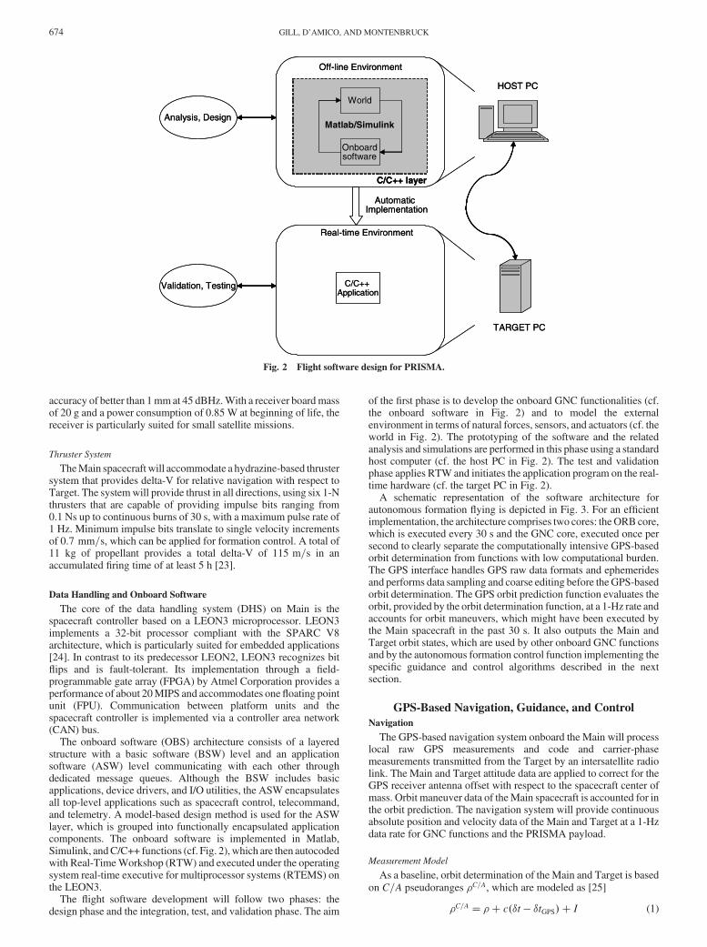
The onboard software (OBS) architecture consists of a layeredstructure with a basic software (BSW) level and an applicationsoftware (ASW) level communicating with each other throughdedicated message queues. Although the BSW includes basicapplications, device drivers, and I/O utilities, the ASW encapsulatesall top-level applications such as spacecraft control, telecommand,and telemetry. A model-based design method is used for the ASWlayer, which is grouped into functionally encapsulated applicationcomponents. The onboard software is implemented in Matlab,Simulink, andC/C++ functions (cf. Fig. 2), which are then autocodedwith Real-TimeWorkshop (RTW) and executed under the operatingsystem real-time executive for multiprocessor systems (RTEMS) onthe LEON3.
The flight software development will follow two phases: thedesign phase and the integration, test, and validation phase. The aim
of the first phase is to develop the onboard GNC functionalities (cf.the onboard software in Fig. 2) and to model the externalenvironment in terms of natural forces, sensors, and actuators (cf. theworld in Fig. 2). The prototyping of the software and the relatedanalysis and simulations are performed in this phase using a standardhost computer (cf. the host PC in Fig. 2). The test and validationphase applies RTW and initiates the application program on the real-time hardware (cf. the target PC in Fig. 2).
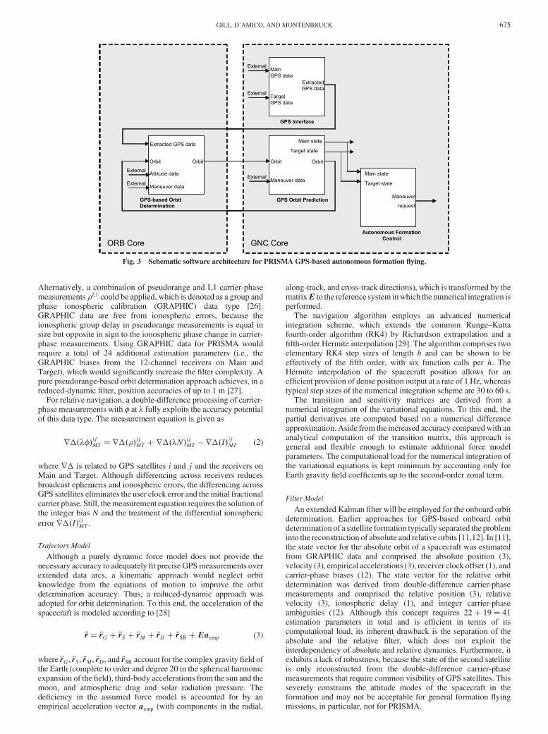
A schematic representation of the software architecture forautonomous formation flying is depicted in Fig. 3. For an efficientimplementation, the architecture comprises two cores: theORBcore,which is executed every 30 s and the GNC core, executed once persecond to clearly separate the computationally intensive GPS-basedorbit determination from functions with low computational burden.The GPS interface handles GPS raw data formats and ephemeridesand performs data sampling and coarse editing before the GPS-basedorbit determination. The GPS orbit prediction function evaluates theorbit, provided by the orbit determination function, at a 1-Hz rate andaccounts for orbit maneuvers, which might have been executed bythe Main spacecraft in the past 30 s. It also outputs the Main andTarget orbit states, which are used by other onboard GNC functionsand by the autonomous formation control function implementing thespecific guidance and control algorithms described in the nextsection.
GPS-Based Navigation, Guidance, and Control
Navigation
The GPS-based navigation system onboard the Main will processlocal raw GPS measurements and code and carrier-phasemeasurements transmitted from the Target by an intersatellite radiolink. The Main and Target attitude data are applied to correct for theGPS receiver antenna offset with respect to the spacecraft center ofmass. Orbit maneuver data of theMain spacecraft is accounted for inthe orbit prediction. The navigation system will provide continuousabsolute position and velocity data of the Main and Target at a 1-Hzdata rate for GNC functions and the PRISMA payload.
Measurement Model
As a baseline, orbit determination of the Main and Target is basedon C=A pseudoranges �C=A, which are modeled as [25]
�C=A �� c��t � �tGPS� � I (1)
Off-line Environment
Real-time Environment
Analysis, Design
Validation, Testing
AutomaticImplementation
Onboardsoftware
World
C/C++ layer
Matlab/Simulink
C/C++Application
TARGET PC
Off-line Environment
Real-time Environment
Analysis, Design
Validation, Testing
AutomaticImplementation
Onboardsoftware
World
Matlab/Simulink
C/C++Application
TARGET PC
HOST PCHOST PC
C/C++ layer
Fig. 2 Flight software design for PRISMA.
674 GILL, D’AMICO, AND MONTENBRUCK
Alternatively, a combination of pseudorange and L1 carrier-phasemeasurements �L1 could be applied, which is denoted as a group andphase ionospheric calibration (GRAPHIC) data type [26].GRAPHIC data are free from ionospheric errors, because theionospheric group delay in pseudorange measurements is equal insize but opposite in sign to the ionospheric phase change in carrier-phase measurements. Using GRAPHIC data for PRISMA wouldrequire a total of 24 additional estimation parameters (i.e., theGRAPHIC biases from the 12-channel receivers on Main andTarget), which would significantly increase the filter complexity. Apure pseudorange-based orbit determination approach achieves, in areduced-dynamic filter, position accuracies of up to 1 m [27].
For relative navigation, a double-difference processing of carrier-phase measurements with � at � fully exploits the accuracy potentialof this data type. The measurement equation is given as
r�����ijMT r����ijMT �r���N�
ijMT � r��I�
ijMT (2)
where r� is related to GPS satellites i and j and the receivers onMain and Target. Although differencing across receivers reducesbroadcast ephemeris and ionospheric errors, the differencing acrossGPS satellites eliminates the user clock error and the initial fractionalcarrier phase. Still, themeasurement equation requires the solution ofthe integer bias N and the treatment of the differential ionospheric
error r��I�ijMT .
Trajectory Model
Although a purely dynamic force model does not provide thenecessary accuracy to adequately fit precise GPSmeasurements overextended data arcs, a kinematic approach would neglect orbitknowledge from the equations of motion to improve the orbitdetermination accuracy. Thus, a reduced-dynamic approach wasadopted for orbit determination. To this end, the acceleration of thespacecraft is modeled according to [28]
�r �rG � �rS � �rM � �rD � �rSR �Eaemp (3)
where �rG, �rS, �rM, �rD, and �rSR account for the complex gravity field ofthe Earth (complete to order and degree 20 in the spherical harmonicexpansion of the field), third-body accelerations from the sun and themoon, and atmospheric drag and solar radiation pressure. Thedeficiency in the assumed force model is accounted for by anempirical acceleration vector aemp (with components in the radial,
along-track, and cross-track directions), which is transformed by thematrixE to the reference system inwhich the numerical integration isperformed.
The navigation algorithm employs an advanced numericalintegration scheme, which extends the common Runge–Kuttafourth-order algorithm (RK4) by Richardson extrapolation and afifth-order Hermite interpolation [29]. The algorithm comprises twoelementary RK4 step sizes of length h and can be shown to beeffectively of the fifth order, with six function calls per h. TheHermite interpolation of the spacecraft position allows for anefficient provision of dense position output at a rate of 1 Hz, whereastypical step sizes of the numerical integration scheme are 30 to 60 s.
The transition and sensitivity matrices are derived from anumerical integration of the variational equations. To this end, thepartial derivatives are computed based on a numerical differenceapproximation. Aside from the increased accuracy comparedwith ananalytical computation of the transition matrix, this approach isgeneral and flexible enough to estimate additional force modelparameters. The computational load for the numerical integration ofthe variational equations is kept minimum by accounting only forEarth gravity field coefficients up to the second-order zonal term.
Filter Model
An extended Kalman filter will be employed for the onboard orbitdetermination. Earlier approaches for GPS-based onboard orbitdetermination of a satellite formation typically separated the probleminto the reconstruction of absolute and relative orbits [11,12]. In [11],the state vector for the absolute orbit of a spacecraft was estimatedfrom GRAPHIC data and comprised the absolute position (3),velocity (3), empirical accelerations (3), receiver clock offset (1), andcarrier-phase biases (12). The state vector for the relative orbitdetermination was derived from double-difference carrier-phasemeasurements and comprised the relative position (3), relativevelocity (3), ionospheric delay (1), and integer carrier-phaseambiguities (12). Although this concept requires 22� 19 41estimation parameters in total and is efficient in terms of itscomputational load, its inherent drawback is the separation of theabsolute and the relative filter, which does not exploit theinterdependency of absolute and relative dynamics. Furthermore, itexhibits a lack of robustness, because the state of the second satelliteis only reconstructed from the double-difference carrier-phasemeasurements that require common visibility of GPS satellites. Thisseverely constrains the attitude modes of the spacecraft in theformation and may not be acceptable for general formation flyingmissions, in particular, not for PRISMA.
MAIN GPS data
TARGET GPS data
Extracted GPS data
GPS Interface
GPS-based Orbit Determination
Extracted GPS data
Attitude data
Maneuver data
Orbit
MAIN state
GPS Orbit Prediction
Maneuver data
TARGET state
Autonomous Formation Control
MAIN state
TARGET state
Orbit
ORB Core
External
External
Orbit
Maneuver
request
External
Orbit
GNC Core
External
External
Main GPS data
Target GPS data
Extracted GPS data
GPS Interface
GPS-based Orbit Determination
Extracted GPS data
Attitude data
Maneuver data
Orbit
Main state
GPS Orbit Prediction
Maneuver data
Target state
Autonomous Formation Control
Main state
Target state
Orbit
ORB Core
External
External
Orbit
Maneuver
request
External
Orbit
GNC Core
External
External
Fig. 3 Schematic software architecture for PRISMA GPS-based autonomous formation flying.
GILL, D’AMICO, AND MONTENBRUCK 675
An innovative filter concept was developed for PRISMA thatemploys a common Kalman filter for the absolute states of Main andTarget without the need for an explicit relative state. It appliespseudorange data from Main and Target to estimate their absoluteorbits and double-difference carrier-phase measurements toimplicitly determine their relative orbit with high precision. Theassociated 35-dimensional state vector x is given by
x �rM; vM;aempM;CDM ; �tM; rT; vT;aempT; CDT ; �tT; I;N� (4)
which comprises the absolute position r (3), absolute velocity v (3),empirical acceleration aemp (3), drag coefficient CD (1), receiverclock offset �t (1), ionospheric zenith delay I (1), and the vector ofinteger carrier-phase ambiguities N (12). This concept provides asymmetric filter design in terms of Main and Target, which fullyexploits the dynamic information for absolute and relative motion.Although the accuracy of the absolute states is only slightlyimproved by the addition of double-difference carrier phases, theaccuracy of the relative state, which is easily derived by thedifference of the absolute states, takes maximum advantage from thehighly precise double-difference carrier phases, because integerambiguities are solved. Furthermore, the filter design assuresrobustness in case Main and Target do not have common GPSsatellites in view. Finally, the handling of orbit maneuvers is greatlysimplified, because the concept of absolute and relative navigation isabandoned.
Because the Phoenix GPS receiver provides its measurementssynchronized to integer GPS seconds, the filter implementation isalso simplified, because a common measurement epoch ti can bechosen for which the Main and Target pseudorange and carrierphases are available. The time update of the filter at step i comprisesthe interpolation of the orbit polynomials at time ti to assemble thepredicted state vector x�i and to compute the associated covariancematrix P�i based on the transition matrix �i and the process noisematrix [28] Qi
x �i xhti; x�ti�1� x�i�1
i; P�i �iP
�i�1�
Ti �Qi (5)
The measurement update phase is then given by
Ki P�i GTi �W�1i � GiP�i GTi ��1
x�i x�i �Ki�zi � gi�; P�i �1 � KiGi�P�i(6)
It is noted that scalar measurement updates are applied to avoid time-consuming matrix-vector operations.
A process noise matrix is employed to cope with residualmodeling deficiencies and to keep the Kalman filter receptive to newmeasurements. To increasingly decorrelate estimates of theempirical accelerations and receiver clock offsets with the timedifference of subsequent filter updates dt, their correspondingcomponents of the process noisematrixQa andQclk are derived froma Gauss–Markov model for the empirical accelerations and a whitenoise model for the clock state according to
Qa 2a1 � exp��2dt=�a��; Qclk 2clkdt=�clk (7)
with the respective process noise amplitudes a and clk and theircharacteristic process noise time scales �a and �clk.
Guidance and Control
The GPS-based navigation system on PRISMA will becomplemented by guidance and control algorithms to conduct anexperiment demonstrating a fully autonomous, robust, and preciseformation flying of spacecraft. To this end, fuel-optimized formationflying at typical distances of 100 to 2000 m is foreseen, which isrepresentative of future satellite formation flying missions [30] thatwill implement interferometric SAR applications.
Linear Relative Motion Model
The relative motion of the Main spacecraft is described in Hill’s[13] coordinate frame, centered at the position of the Targetspacecraft. Its orientation is given by the triad of unit vectorsfeR; eT; eNg, where eR is aligned with the radial direction (positiveoutwards) and eN is parallel to the orbit momentum vector. Thevector eT then completes the right-hand coordinates system. Therelative position and velocity vectors of Main with respect to Target�r and �v are expressed in the Hill frame as
�r rM � r�rReR ��rTeT ��rNeN
�v vM � v�vReR ��vTeT ��vNeN(8)
where r and v and rM and vM are the inertial position and velocityvectors of Target and Main, respectively. In the following, thesubscript M denotes the Main parameters, whereas no subscript isused for Target.
In parallel with a Hill [13] Cartesian coordinates representation ofthe relative motion, a description in terms of relative orbital elementscan be adopted that simplifies the formation flying design and givesimmediate insight into the geometry of the constellation [9]. Therelative orbital elements parameterization is based on the relativesemi-major axis�a, the relative mean argument of latitude�u, therelative eccentricity vector �e ��ex;�ey�T , and the relativeinclination vector �i ��ix;�iy�T . The six relative orbitalelements are defined as the difference of the orbital elements ofMainand Target, according to
�a aM � a; �ex eM cos!M � e cos!�ix iM � i; �u uM � u
�ey eM sin!M � e sin!; �iy ��M ��� sin i(9)
The relative eccentricity vector characterizes the periodic in-planerelative motion by combining the Keplerian elements e and !. Therelative inclination vector characterizes the periodic out-of-planerelative motion by combining the Keplerian elements i and �. Themean argument of latitude is the sum of the argument of perigee andthe mean anomaly (i.e., u !�M).
Depending on the specific application, either a Cartesian or a polarrepresentation of the relative e=i vectors is preferable with thenotation
�e �e�cos’sin ’
�; �i �i
�sin �cos �
�(10)
The amplitudes of the relative e=i vectors are �e and �i, and thephases of the relative e=i vectors are ’ and �.
The description of the relative motion in terms of the Cartesiancoordinates vector �r defined in Eq. (8) can be derived from theClohessy–Wiltshire (CW) equations [14]. The general closed-formsolution of the CW equations using the mean argument of latitude asan independent variable [31] is
8>><>>:�rR=a�a=a � �e cos�u � ’��rT=a�l� �3=2���a=a��u � u0� � 2�e sin�u � ’��rN=a �i sin�u � ��
(11)
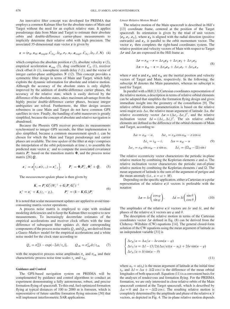
where u0 u�t0� is the mean argument of latitude at the initial timet0, and �l�u���cos i is the difference of the mean orbitallongitudes of both spacecraft. Equation (11) is a convenient basis forthe analyses of rendezvous and formation flying. For the PRISMAformation, we are only interested in close relative orbits of the Mainspacecraft centered at the Target spacecraft, which is described by�a 0 and �u���cos i. The resulting relative motion iscompletely determined by the amplitude and phase of the relative e=ivectors, as depicted in Fig. 4. The in-plane relative motion depends
676 GILL, D’AMICO, AND MONTENBRUCK
on the relative eccentricity vector, whereas the out-of-plane motiondepends on both the eccentricity and inclination vectors.
Collision avoidance between the PRISMA spacecraft can easilybe handled bymeans of the e=i vector separation concept. For (anti-)parallel e=i vectors (i.e., ’ �), the minimum distance betweenMain and Target is given by min�a�e; a�i�. The projection of therelative trajectory onto the orbital plane is an ellipse of the semi-major axis 2a�e in the along-track direction and of the semi-minoraxis a�e in the radial direction. The projection onto the planeperpendicular to the flight direction is an ellipse of the semi-majoraxis max�a�e; a�i� and the semi-minor axis min�a�e; a�i�, in theradial and cross-track directions. This describes a collision-freeconfiguration in which radial and cross-track separations nevervanish at the same time (i.e., at the same mean argument of latitude).Perpendicular e=i vectors denote, instead, a dangerous configura-tion, especially in the case of large uncertainties in along-trackseparation.
The relative motion of formation flying spacecraft in the presenceof an oblate Earth may be derived from the inclusion of perturbationsof J2 into the linear relative motion model. Following Brouwer [19]and Lyddane [20], the J2 short-period variations of the orbitalelements only depend on the mean argument of latitude.Consequently, these perturbations can be neglectedwhen computingthe relative orbital elements for close formation flying satellites. Theremaining J2 effects are the secular variations of the argument ofperigee, the right ascension of the ascending node, and the meananomaly
d!
du 3
2��5cos2i � 1�; d�
du�3� cos i
dM
du 1� 3
2�
�������������1 � e2p
�3cos2i � 1�(12)
with
� J22
�R�a
�2 1
�1 � e2�2 (13)
Upon substituting Eq. (12) into the derivatives of the relative orbitalelements defined by Eq. (9) and integrating over an arbitrary timeinterval, we obtain, to first order in the relative orbital elements, thesecular growth of the relative orbital elements. The resulting linearrelative motion model is
8>>>>><>>>>>:
�rR=a�a=a � �e cos’0 � ’0�u � u0���rT=a
��l0 � 21
2��ix�u � u0� sin 2i
�
� 32�aa�u � u0� � 2�e sin’0 � ’0�u � u0��
�rN=a ��iy0 � 3��ix�u � u0�sin2i� cos u��ix sinu
(14)
where the subscript 0 was introduced for the initial conditions oftime-dependent elements and
’0 d’
du 3
2��5cos2i� 1� (15)
is the derivative of the relative perigee. Only the relative semi-majoraxis �a and the x component of the relative inclination vector �ixare not affected by the J2 perturbations. The other relative orbitalelements experience a secular trend that is directly proportional to theelapsed time (i.e., u � u0). In particular, the relative eccentricityvector evolves along a circle of radius �e, being centered at the originof the e vector plane and traversed at an angular velocity given byEq. (15). The relative inclination vector is likewise affected by J2perturbations causing a linear drift of the �iy componentproportional to inclination difference�ix. Finally, the relative meanlongitude between the spacecraft exhibits a secular trend that isproportional to the inclination difference.
Impulsive Relative Orbit Control
The maintenance of the PRISMA formation requires theperformance of maneuvers to counteract gravitational perturbationsdue mainly to J2 and differential drag effects. Among the variouscontrol methods, an impulsive feedback control was selected thatminimizes the number of maneuvers, as shown in previous studies[32], while maximizing the time for data collection.
The equations for the impulsive relative orbit control of spacecraftin near-circular nonequatorial orbits are obtained through theintegration of the Gauss variational equations over the impulsivemaneuver, as8>>>>>>>>><
>>>>>>>>>:
��a=a�2 ��vT��u�2 ��vR � sin u
tan i��vN
��ex � sin u ��vR � 2 cos u ��vT��ey � cos u ��vR � 2 sin u ��vT��ix � cos u ��vN��iy � sin u ��vN
(16)
where �v =a2��vR;�vT;�vN�T denotes the velocity incre-ments expressed in the Hill [13] frame, and ����� is the operatorrepresenting the difference between the relative orbital elements ofMain after and before the maneuver impulse.
The relative orbit control system must be able to plan and executecorrection maneuvers in accordance with predefined nominalrelative orbital elements�aN;�uN;�eN; and �iN . In general, theactual orbital differences �a;�u;�e; and �i are confined withinsymmetric control windows centered around the nominal values. Inthis case, the control error of each of the relative orbital elementsk��� �k k�� � ��� �Nkmust be confinedwithin������max, witha total control window of 2�����max for each relative orbital element.In the sequel, the relative orbital elements are understood as meanrelative elements in which the J2 short-period perturbations havebeen removed using the algorithms of Brouwer [19] and Lyddane[20].
The relative inclination vector is optimally corrected by a singlecross-track impulse, given by
�vN 2k��ik; u arctan��iy��ix
(17)
where ��i ��iN ��i� is the tracking error of the relativeinclination vector computed at the time of the impulse. Applying this
eR
eT
eN
eR
eaδ
eaδ2
eaδ
iaδ
ϕ−u
Main
Target
ϕ=u
2πϕ +=u
πϕ +=u
23πϕ +=u
θ=u
2πθ +=u
πθ +=u
23πθ +=u
Main
Target
θ−u
Fig. 4 Relative motion of Main with respect to Target, with e=i vectorseparation; in-plane (top) and out-of-plane (bottom) motion in the Hill
[13] frame.
GILL, D’AMICO, AND MONTENBRUCK 677
maneuver corrects the relative inclination vector, but affects therelative mean argument of latitude. The undesired cross coupling ismaximum if the thrust is performed at the extreme southern/northernlatitudes, minimum if performed at the equator crossings, andultimately depends on the magnitude of the desired correction of therelative inclination vector (i.e., on the out-of-plane maneuver cycle).
The correction of the remaining relative orbital elements isperformed with two along-track impulsive maneuvers withamplitudes �v1T and �v2T , located at the argument of latitudes u1
and u2:
�v1T 14�2k��ek � ��a=a�; u1 arctan
��ey��ex
�v2T �14�2k��ek � ��a=a�; u2 u1 �
(18)
where ��e ��eN ��e� is the tracking error of the relativeeccentricity vector, and ��a�aN ��a is the tracking error of therelative semi-major axis. Both ��e and ��a have to be computedbefore the first impulse (i.e.,�v1T) for a real-time implementation ofthe feedback control law.
The correction of the relative mean argument of latitude isobtained through Eq. (18) via a proper choice of the nominal relativesemi-major axis �aN . In contrast to the other relative orbitalelements, �u cannot be changed simultaneously by a tangentialmaneuver. Instead, a desiredmean longitude drift is introduced in thetime between the maneuver pairs, so that the mean along-trackseparation of the spacecraft can be confined within the desiredlongitude window.
The computation of the nominal relative semi-major axis is crucialfor the firing scheme, because �aN depends on the a prioriknowledge of the mean relative longitude drift experienced by theformation flying spacecraft. The size of �aN in Eq. (18) can bederived from an analytical estimation of the secular variation of themean relative argument of latitude �uT , which includes theperturbations from J2,�uJ2, and from differential drag,�uD. UsingEq. (14), we obtain
�uT �uJ2 ��uD �12� sin�2i��ixn�t�"jdDj2a
�t2 (19)
where � �BM � B�=B is the relative difference between theballistic coefficients ofMain (BM) and Target (B). We can now closethe deterministic feedback control law evaluating the nominalrelative semi-major axis for the next in-plane maneuver cycle, as
�aN � 2
3
a2
v
��uN � 2��umax ��uT��t
(20)
where ��umax has to be selected such as to guarantee a mean relativelongitude window centered on the nominal relative mean argumentof latitude �uN , according to
��umax j � 32 �v1T j (21)
The impulsive control law given byEqs. (17–21) is simple, requires alow computational burden, and is thus ideally suited for an onboardautonomous implementation. The disadvantage of the presentedalgorithm is the necessity to analytically determine the drift of therelative mean argument latitude. Applied to PRISMA, the methodrelies on the knowledge of the differential drag acceleration betweenthe Main and Target spacecraft.
Concept Validation
Navigation
The presented concept for GPS-based absolute and relativenavigation was validated within a hardware-in-the-loop (HIL)demonstration. To this end, a signal simulator generated GPS signalsfor a LEO space scenario, which were received by Orion’s GPSreceivers (the predecessor of Phoenix, with comparable perform-ance). The raw GPS measurements were transferred through radiomodems to a central navigation computer for subsequent filtering
[11]. For the relative motion of two spacecraft, an ellipse with 4-kmmaximum along-track separation and 2-km radial separation wasadopted that is representative for the PRISMA mission.
Results from HIL demonstrations for relative navigation exhibit arelative navigation accuracy (3-D RSS) after convergence is about1.5mm in relative position and 5 m=s in relative velocity. At largerseparations of 10–50 km, this accuracy degrades to 10 cmmaximum,due to differential broadcast ephemeris and ionospheric errors.Although this accuracy may not be achievable for PRISMA due tomultipath effects, coverage problems, and heavy maneuver activity,real-time relative navigation accuracies of better than 0.1 m (3DRSS) are expected. For absolute navigation, a position accuracy ofbetter than 2 m will be achieved that is largely governed by GPSbroadcast ephemeris errors.
In addition to the onboard navigation, an onground ex postfactotrajectory reconstruction will provide precise absolute and relativeposition and velocity data for verification and calibration purposes.In this context, ionosphere-free code-carrier combinations allow theestimation of absolute positions of the two PRISMA spacecraft witha 3-D accuracy of better than 0.5 m [26], and, subject to multipathavoidance and good common satellite visibility, relative positionswith centimeter accuracy. The improvements over an onboardprocessing stem from the use of precise GPS clock and ephemerisdata, distributed by the International GNSS Service (IGS), and fromthe use of more elaborate data editing and ambiguity resolutionalgorithms.
Guidance and Control
Even if ’ � =2 represents a constellation geometry withminimum collision risk, it does not always satisfy the sciencerequirements, especially with SAR interferometric missions such as,for example, TanDEM-X [9]. To preserve the generality of theproblem, the following representative formation flying configurationwas selected:
a�eN 500 m; ’N 80 deg
a�iN 300 m; �N 50 deg(22)
where a 7078:137 km. The relative inclination vector has anonzero x component, resulting in an inclination difference betweenthe spacecraft orbits of �ix 1:56 � 10�3 deg. Furthermore,selecting
�aN 0; a�uN �a�iy= tan i 33:1 m (23)
where i 98:2 deg provides closed relative trajectories of Maincentered around Target. An appropriate choice for the controlwindows is given by
a��imax 5 m; a��emax 7 m; a��umax 20 m
(24)
The objective of the following concept validation is to demonstratethe feasibility of the proposed orbit guidance and control concept andestimate the performance of the impulsive feedback control law. Theguidance function comprises the computation of the difference of theactual and the nominal mean relative elements and the evaluation ofdeadband violations based on the defined control windows. Thecontrol function derives the maneuver times and sizes to shift therelative eccentricity/inclination vectors to the opposite side of thecontrol window.
The described nominal formation configuration was simulatedover a three-week time interval. To this end, a realistic dynamicmodel was applied in the numerical integration of the spacecraftmotion. It comprises the Earth gravity model GGM01S up to orderand degree 20, the lunisolar third-body gravitational perturbation, thelunisolar solid Earth tides, the atmospheric drag, and the solarradiation pressure. All models are supplemented by associated Earthrotation parameters and solar-geomagnetic data. Instead of using adedicated orbit determination process, the GPS-based relativenavigation filter was emulated by the nominal trajectories and
678 GILL, D’AMICO, AND MONTENBRUCK
specific relative navigation errors. The control law applies a secularvariation of the mean relative argument of latitude in Eq. (19), basedupon an atmospheric density � 0:11946 g=km3 and ballisticcoefficients BM 0:045 m2=kg and BT 0:019 m2=kg for Mainand Target, respectively. The relative difference of the appliedballistic coefficients corresponds to �� 140% and is of particularrelevance in the simulation.
The simulation models realistic sensors and actuators. A drivingfactor for the performance of the relative orbit control is thepropulsion system’s minimum impulse bit (MIB) of 0:7 mm=s, (i.e.,the thrusters can only realize delta-V as integer multiples of theMIB). Furthermore, the thruster execution error � is treated asGaussian noise with 2% mean and a standard deviation of 1%. Theperformance of the GPS-based relative navigation filter is emulatedusing errors��, consisting of a bias of 0.1mandGaussian noisewitha standard deviation of 0.05m. Finally, the attitude control errors��are accounted for by Gaussian noise with 0.8-deg standard deviationin three axes. This implies a thrust direction misalignment, whichcauses a cross coupling between tangential and normal maneuversand introduces unintentional velocity variations in radial direction.
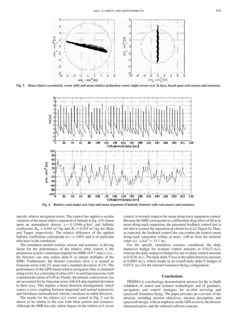
The results for the relative e=i vector control in Fig. 5 can beshown to be similar to the case with ideal sensors and actuators.Although the MIB has only minor impact on the relative e=i vector
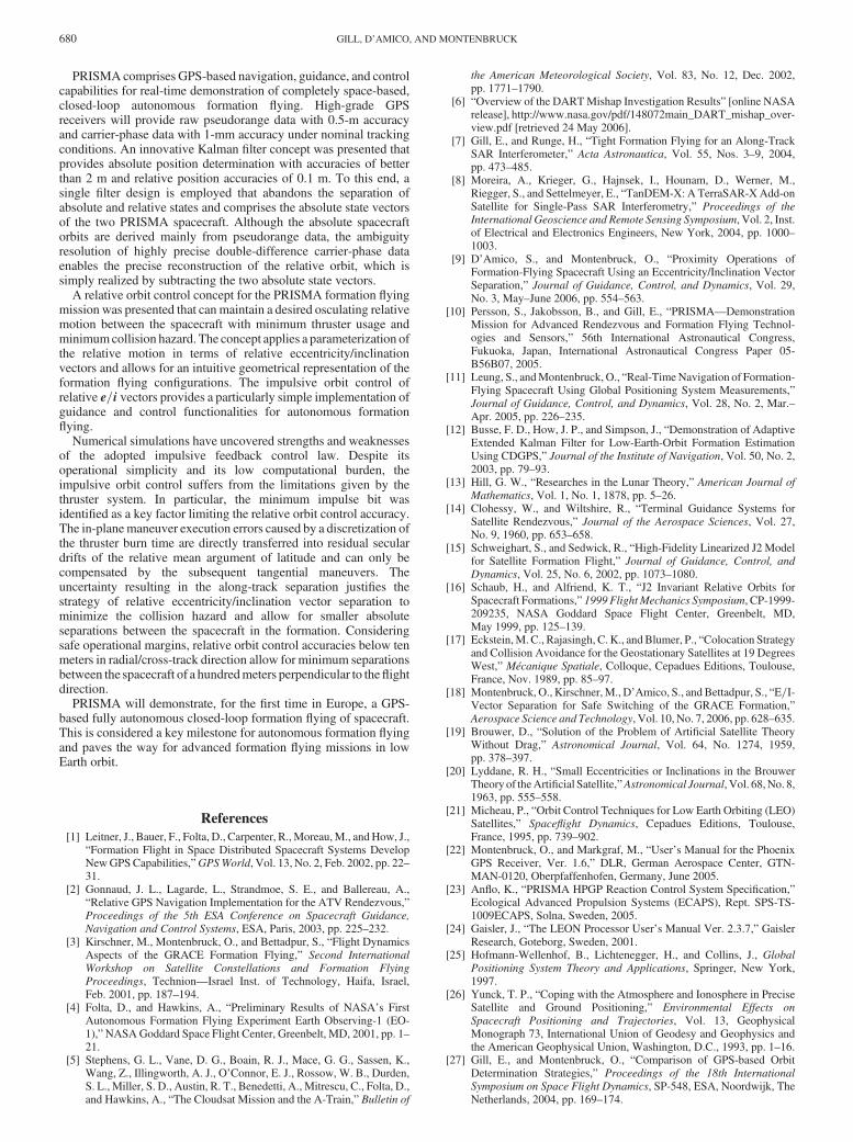
control, it severely impacts the mean along-track separation control.Because the MIB corresponds to a differential drag effect of 60 m inmean along-track separation, the presented feedback control law isnot able to control the separation at a better level (cf. Figure 6). Thus,as expected, the feedback control law can confine the relative meanalong-track separation within, at most, �60 m from the nominalvalue (i.e., a�uN 33:1 m).
For the specific simulation scenario considered, the dailymaneuver budget for in-plane control amounts to 0:0133 m=s,whereas the daily maneuver budget for out-of-plane control amountsto 0:0236 m=s. The daily delta-V loss in the radial direction amountsto 0:0003 m=s, which results in an overall daily delta-V budget of0:0372 m=s for the selected formation flying configuration.
Conclusions
PRISMA is a technology demonstration mission for the in-flightvalidation of sensor and actuator technologies and of guidance,navigation, and control strategies for in-orbit servicing andspacecraft formation flying. The paper provides an overview of themission, including mission objectives, mission description, andspacecraft design, with an emphasis on the GPS receiver, the thrustercharacterization, and the onboard software concept.
Fig. 5 Mean relative eccentricity vector (left) and mean relative inclination vector (right) errors over 21 days, based upon real sensors and actuators.
Fig. 6 Relative semi-major axis (top) and mean argument of latitude (bottom) with real sensors and actuators.
GILL, D’AMICO, AND MONTENBRUCK 679
PRISMA comprises GPS-based navigation, guidance, and controlcapabilities for real-time demonstration of completely space-based,closed-loop autonomous formation flying. High-grade GPSreceivers will provide raw pseudorange data with 0.5-m accuracyand carrier-phase data with 1-mm accuracy under nominal trackingconditions. An innovative Kalman filter concept was presented thatprovides absolute position determination with accuracies of betterthan 2 m and relative position accuracies of 0.1 m. To this end, asingle filter design is employed that abandons the separation ofabsolute and relative states and comprises the absolute state vectorsof the two PRISMA spacecraft. Although the absolute spacecraftorbits are derived mainly from pseudorange data, the ambiguityresolution of highly precise double-difference carrier-phase dataenables the precise reconstruction of the relative orbit, which issimply realized by subtracting the two absolute state vectors.
A relative orbit control concept for the PRISMA formation flyingmission was presented that canmaintain a desired osculating relativemotion between the spacecraft with minimum thruster usage andminimumcollision hazard. The concept applies a parameterization ofthe relative motion in terms of relative eccentricity/inclinationvectors and allows for an intuitive geometrical representation of theformation flying configurations. The impulsive orbit control ofrelative e=i vectors provides a particularly simple implementation ofguidance and control functionalities for autonomous formationflying.
Numerical simulations have uncovered strengths and weaknessesof the adopted impulsive feedback control law. Despite itsoperational simplicity and its low computational burden, theimpulsive orbit control suffers from the limitations given by thethruster system. In particular, the minimum impulse bit wasidentified as a key factor limiting the relative orbit control accuracy.The in-planemaneuver execution errors caused by a discretization ofthe thruster burn time are directly transferred into residual seculardrifts of the relative mean argument of latitude and can only becompensated by the subsequent tangential maneuvers. Theuncertainty resulting in the along-track separation justifies thestrategy of relative eccentricity/inclination vector separation tominimize the collision hazard and allow for smaller absoluteseparations between the spacecraft in the formation. Consideringsafe operational margins, relative orbit control accuracies below tenmeters in radial/cross-track direction allow for minimum separationsbetween the spacecraft of a hundredmeters perpendicular to theflightdirection.
PRISMA will demonstrate, for the first time in Europe, a GPS-based fully autonomous closed-loop formation flying of spacecraft.This is considered a key milestone for autonomous formation flyingand paves the way for advanced formation flying missions in lowEarth orbit.
References
[1] Leitner, J., Bauer, F., Folta, D., Carpenter, R.,Moreau,M., andHow, J.,“Formation Flight in Space Distributed Spacecraft Systems DevelopNewGPSCapabilities,”GPSWorld, Vol. 13, No. 2, Feb. 2002, pp. 22–31.
[2] Gonnaud, J. L., Lagarde, L., Strandmoe, S. E., and Ballereau, A.,“Relative GPS Navigation Implementation for the ATV Rendezvous,”Proceedings of the 5th ESA Conference on Spacecraft Guidance,
Navigation and Control Systems, ESA, Paris, 2003, pp. 225–232.[3] Kirschner, M., Montenbruck, O., and Bettadpur, S., “Flight Dynamics
Aspects of the GRACE Formation Flying,” Second International
Workshop on Satellite Constellations and Formation Flying
Proceedings, Technion—Israel Inst. of Technology, Haifa, Israel,Feb. 2001, pp. 187–194.
[4] Folta, D., and Hawkins, A., “Preliminary Results of NASA’s FirstAutonomous Formation Flying Experiment Earth Observing-1 (EO-1),”NASAGoddard Space Flight Center, Greenbelt, MD, 2001, pp. 1–21.
[5] Stephens, G. L., Vane, D. G., Boain, R. J., Mace, G. G., Sassen, K.,Wang, Z., Illingworth, A. J., O’Connor, E. J., Rossow, W. B., Durden,S. L., Miller, S. D., Austin, R. T., Benedetti, A., Mitrescu, C., Folta, D.,and Hawkins, A., “The Cloudsat Mission and the A-Train,” Bulletin of
the American Meteorological Society, Vol. 83, No. 12, Dec. 2002,pp. 1771–1790.
[6] “Overview of the DARTMishap Investigation Results” [online NASArelease], http://www.nasa.gov/pdf/148072main_DART_mishap_over-view.pdf [retrieved 24 May 2006].
[7] Gill, E., and Runge, H., “Tight Formation Flying for an Along-TrackSAR Interferometer,” Acta Astronautica, Vol. 55, Nos. 3–9, 2004,pp. 473–485.
[8] Moreira, A., Krieger, G., Hajnsek, I., Hounam, D., Werner, M.,Riegger, S., and Settelmeyer, E., “TanDEM-X: A TerraSAR-XAdd-onSatellite for Single-Pass SAR Interferometry,” Proceedings of the
International Geoscience and Remote Sensing Symposium, Vol. 2, Inst.of Electrical and Electronics Engineers, New York, 2004, pp. 1000–1003.
[9] D’Amico, S., and Montenbruck, O., “Proximity Operations ofFormation-Flying Spacecraft Using an Eccentricity/Inclination VectorSeparation,” Journal of Guidance, Control, and Dynamics, Vol. 29,No. 3, May–June 2006, pp. 554–563.
[10] Persson, S., Jakobsson, B., and Gill, E., “PRISMA—DemonstrationMission for Advanced Rendezvous and Formation Flying Technol-ogies and Sensors,” 56th International Astronautical Congress,Fukuoka, Japan, International Astronautical Congress Paper 05-B56B07, 2005.
[11] Leung, S., andMontenbruck, O., “Real-TimeNavigation of Formation-Flying Spacecraft Using Global Positioning System Measurements,”Journal of Guidance, Control, and Dynamics, Vol. 28, No. 2, Mar.–Apr. 2005, pp. 226–235.
[12] Busse, F. D., How, J. P., and Simpson, J., “Demonstration of AdaptiveExtended Kalman Filter for Low-Earth-Orbit Formation EstimationUsing CDGPS,” Journal of the Institute of Navigation, Vol. 50, No. 2,2003, pp. 79–93.
[13] Hill, G. W., “Researches in the Lunar Theory,” American Journal of
Mathematics, Vol. 1, No. 1, 1878, pp. 5–26.[14] Clohessy, W., and Wiltshire, R., “Terminal Guidance Systems for
Satellite Rendezvous,” Journal of the Aerospace Sciences, Vol. 27,No. 9, 1960, pp. 653–658.
[15] Schweighart, S., and Sedwick, R., “High-Fidelity Linearized J2 Modelfor Satellite Formation Flight,” Journal of Guidance, Control, and
Dynamics, Vol. 25, No. 6, 2002, pp. 1073–1080.[16] Schaub, H., and Alfriend, K. T., “J2 Invariant Relative Orbits for
Spacecraft Formations,” 1999 Flight Mechanics Symposium, CP-1999-209235, NASA Goddard Space Flight Center, Greenbelt, MD,May 1999, pp. 125–139.
[17] Eckstein,M.C., Rajasingh, C.K., andBlumer, P., “Colocation Strategyand Collision Avoidance for the Geostationary Satellites at 19 DegreesWest,” Mécanique Spatiale, Colloque, Cepadues Editions, Toulouse,France, Nov. 1989, pp. 85–97.
[18] Montenbruck, O., Kirschner,M., D’Amico, S., and Bettadpur, S., “E=I-Vector Separation for Safe Switching of the GRACE Formation,”Aerospace Science and Technology, Vol. 10, No. 7, 2006, pp. 628–635.
[19] Brouwer, D., “Solution of the Problem of Artificial Satellite TheoryWithout Drag,” Astronomical Journal, Vol. 64, No. 1274, 1959,pp. 378–397.
[20] Lyddane, R. H., “Small Eccentricities or Inclinations in the BrouwerTheory of theArtificial Satellite,”Astronomical Journal, Vol. 68,No. 8,1963, pp. 555–558.
[21] Micheau, P., “Orbit Control Techniques for Low Earth Orbiting (LEO)Satellites,” Spaceflight Dynamics, Cepadues Editions, Toulouse,France, 1995, pp. 739–902.
[22] Montenbruck, O., and Markgraf, M., “User’s Manual for the PhoenixGPS Receiver, Ver. 1.6,” DLR, German Aerospace Center, GTN-MAN-0120, Oberpfaffenhofen, Germany, June 2005.
[23] Anflo, K., “PRISMA HPGP Reaction Control System Specification,”Ecological Advanced Propulsion Systems (ECAPS), Rept. SPS-TS-1009ECAPS, Solna, Sweden, 2005.
[24] Gaisler, J., “The LEON Processor User’s Manual Ver. 2.3.7,” GaislerResearch, Goteborg, Sweden, 2001.
[25] Hofmann-Wellenhof, B., Lichtenegger, H., and Collins, J., GlobalPositioning System Theory and Applications, Springer, New York,1997.
[26] Yunck, T. P., “Coping with the Atmosphere and Ionosphere in PreciseSatellite and Ground Positioning,” Environmental Effects on
Spacecraft Positioning and Trajectories, Vol. 13, GeophysicalMonograph 73, International Union of Geodesy and Geophysics andthe American Geophysical Union, Washington, D.C., 1993, pp. 1–16.
[27] Gill, E., and Montenbruck, O., “Comparison of GPS-based OrbitDetermination Strategies,” Proceedings of the 18th International
Symposium on Space Flight Dynamics, SP-548, ESA, Noordwijk, TheNetherlands, 2004, pp. 169–174.
680 GILL, D’AMICO, AND MONTENBRUCK

[28] Montenbruck, O., and Gill, E., Satellite Orbits—Models, Methods and
Applications, Springer, Heidelberg, Germany, 2000, pp. 53–116.[29] Montenbruck, O., and Gill, E., “State Interpolation for On-Board
Navigation Systems,” Aerospace Science and Technology, Vol. 5,No. 3, 2001, pp. 209–220.
[30] Gill, E., and Runge, H., “A Tight Formation for Along-Track SARInterferometry,” 2nd International Symposium on Formation Flying
Missions & Technologies [CD-ROM], CP-2005-212781, NASAGoddard Space Flight Center, Greenbelt, MD, 2004.
[31] Richardson, D. L., and Mitchell, J. W., “A Third-Order Analytical
Solution for Relative Motion with a Circular Reference Orbit,” Journalof the Astronautical Sciences, Vol. 51, No. 1, 2003, pp. 1–12.
[32] Vaddi, S. S., Alfriend, K. T., Vadali, S. R., and Sengupta, P.,“Formation Establishment and Reconfiguration Using ImpulsiveControl,” Journal of Guidance, Control, and Dynamics, Vol. 28, No. 2,2005, pp. 262–268.
C. McLaughlinAssociate Editor
GILL, D’AMICO, AND MONTENBRUCK 681