autopilot installation manual - psicompany.com an autopilot is used without the compen-sation,...
TRANSCRIPT
AUTOPILOTNAVpilot-700/711/720
Installation Manual
SYSTEM CONFIGURATION .........................iiEQUIPMENT LISTS......................................iii
1. HOW TO INSTALL THE UNITS............ 1-11.1 Control Unit FAP-7001/FAP-7011...... 1-1
1.1.1 Surface mount.......................... 1-21.1.2 Desktop mount......................... 1-4
1.2 Processor Unit FAP-7002 .................. 1-51.3 Rudder Reference Unit FAP-6112 ..... 1-71.4 Remote Controllers (option) ............... 1-81.5 Distributor FAP-6800 (option) .......... 1-111.6 Control Unit FAP-7021 ..................... 1-121.7 Cable Extension Kit
FAP-7822 (option)............................ 1-12
2. WIRING.................................................. 2-12.1 General Wiring ................................... 2-12.2 Processor Unit.................................... 2-2
2.2.1 Connections inside the processor unit ........................................... 2-2
2.2.2 How to fasten cables to the cable .clamps...................................... 2-3
2.2.3 How to put wires into the connector blocks....................................... 2-4
2.2.4 Power and motor cables .......... 2-52.2.5 Teleflex linear sensor............... 2-72.2.6 CAN bus power........................ 2-82.2.7 Connection to TB4 ................... 2-8
2.3 Control Unit ........................................ 2-82.4 Remote Controllers (option) ............... 2-9
2.4.1 Example remote controllerconnections............................ 2-10
2.4.2 Prohibited remote controllerconnections............................ 2-11
2.5 Input/Output Sentences ................... 2-12
3. INITIAL SETTINGS ............................... 3-13.1 About Initial Settings, Menu Operation3-13.2 How to Select Language and Units,
Open the Installation Menu ................ 3-23.3 Display Setup ..................................... 3-43.4 Ship’s Characteristics Menu............... 3-53.5 Dockside Setup Menu ........................ 3-63.6 CAN bus Port Setup ......................... 3-143.7 NMEA0183 Port Setup ..................... 3-153.8 Sensor Setup.................................... 3-163.9 Universal Port Setup ........................ 3-173.10 Sea Trial ........................................... 3-193.11 Data Calibration................................ 3-223.12 PARAMETER SETUP Menu ........... 3-223.13 AUTO OPTION Menu....................... 3-283.14 NAV OPTION Menu ......................... 3-293.15 FISH HUNTER OPTION Menu or
WIND OPTION Menu....................... 3-313.15.1FISH HUNTER OPTION
menu ...................................... 3-313.15.2WIND OPTION menu............. 3-32
3.16 SYSTEM SETUP Menu.................... 3-333.17 RC (Remote Controller) SETUP
Menu ................................................ 3-343.18 All Clear............................................ 3-34
JIS CABLE GUIDE ................................. AP-1PACKING LISTS........................................A-1OUTLINE DRAWINGS...............................D-1INTERCONNECTION DIAGRAM...............S-1MOUNTING TEMPLATES
www.furuno.co.jpAll brand and product names are trademarks, registered trademarks or service marks of their respective holders.

The paper used in this manual
is elemental chlorine free.
・FURUNO Authorized Distributor/Dealer
9-52 Ashihara-cho,
Nishinomiya, 662-8580, JAPAN
Telephone : +81-(0)798-65-2111
Fax : +81-(0)798-65-4200
A : JAN 2010.Printed in JapanAll rights reserved.
D1 : APR . 27, 2011
Pub. No. IME-72720-D1
*00017181313**00017181313*(DAMI ) NAVpilot-700/711/720*00017181313**00017181313*
* 0 0 0 1 7 1 8 1 3 1 3 *
i
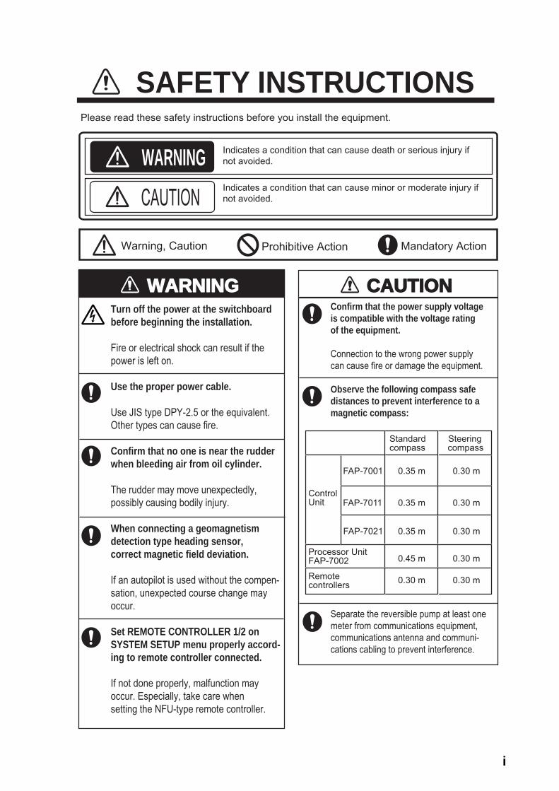
WARNINGWARNINGTurn off the power at the switchboardbefore beginning the installation.
Fire or electrical shock can result if thepower is left on.
Use the proper power cable.
Use JIS type DPY-2.5 or the equivalent.Other types can cause fire.
Confirm that no one is near the rudderwhen bleeding air from oil cylinder.
The rudder may move unexpectedly,possibly causing bodily injury.
When connecting a geomagnetism detection type heading sensor, correct magnetic field deviation.
If an autopilot is used without the compen-sation, unexpected course change may occur.
Set REMOTE CONTROLLER 1/2 on SYSTEM SETUP menu properly accord-ing to remote controller connected.
If not done properly, malfunction may occur. Especially, take care when setting the NFU-type remote controller.
CAUTIONCAUTION
ControlUnit
Standard Steeringcompass compass
0.35 m 0.30 m
Confirm that the power supply voltageis compatible with the voltage rating of the equipment.
Connection to the wrong power supplycan cause fire or damage the equipment.
Observe the following compass safedistances to prevent interference to amagnetic compass:
Separate the reversible pump at least onemeter from communications equipment,communications antenna and communi-cations cabling to prevent interference.
Processor UnitFAP-7002 0.45 m 0.30 m
Remotecontrollers 0.30 m 0.30 m
FAP-7001
FAP-7011 0.35 m 0.30 m
FAP-7021 0.35 m 0.30 m
SAFETY INSTRUCTIONS
WARNING Indicates a condition that can cause death or serious injury ifnot avoided.
CAUTIONIndicates a condition that can cause minor or moderate injury ifnot avoided.
Warning, Caution Mandatory Action Prohibitive Action
Please read these safety instructions before you install the equipment.
ii
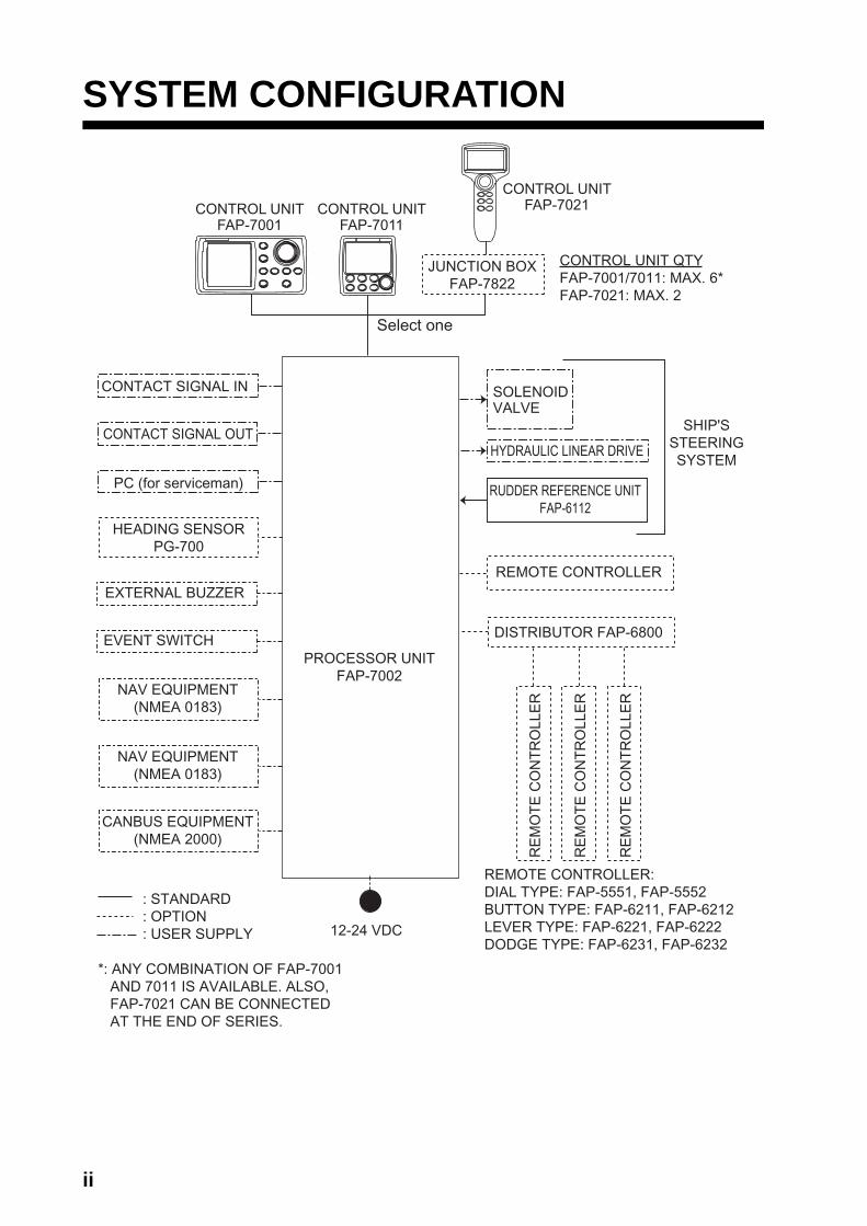
SYSTEM CONFIGURATION
12-24 VDC
PROCESSOR UNITFAP-7002
CONTROL UNIT QTYFAP-7001/7011: MAX. 6* FAP-7021: MAX. 2
RUDDER REFERENCE UNITFAP-6112
DISTRIBUTOR FAP-6800
SOLENOIDVALVE
PC (for serviceman)
EXTERNAL BUZZER
NAV EQUIPMENT(NMEA 0183)
HYDRAULIC LINEAR DRIVE
HEADING SENSORPG-700
SHIP'SSTEERINGSYSTEM
REMOTE CONTROLLER:DIAL TYPE: FAP-5551, FAP-5552BUTTON TYPE: FAP-6211, FAP-6212LEVER TYPE: FAP-6221, FAP-6222DODGE TYPE: FAP-6231, FAP-6232
*: ANY COMBINATION OF FAP-7001 AND 7011 IS AVAILABLE. ALSO, FAP-7021 CAN BE CONNECTED AT THE END OF SERIES.
REMOTE CONTROLLERR
EM
OT
E C
ON
TR
OLL
ER
RE
MO
TE
CO
NT
RO
LLE
R
RE
MO
TE
CO
NT
RO
LLE
R
: STANDARD : OPTION : USER SUPPLY
EVENT SWITCH
NAV EQUIPMENT(NMEA 0183)
CANBUS EQUIPMENT(NMEA 2000)
JUNCTION BOXFAP-7822
Select one
CONTROL UNITFAP-7001
CONTROL UNITFAP-7011
CONTROL UNITFAP-7021
CONTACT SIGNAL IN
CONTACT SIGNAL OUT
iii
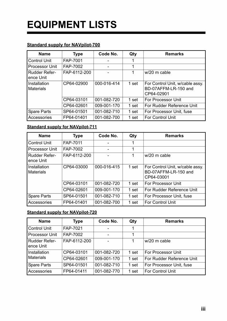
EQUIPMENT LISTS
Standard supply for NAVpilot-700
Standard supply for NAVpilot-711
Standard supply for NAVpilot-720
Name Type Code No. Qty RemarksControl Unit FAP-7001 - 1Processor Unit FAP-7002 - 1Rudder Refer-ence Unit
FAP-6112-200 - 1 w/20 m cable
InstallationMaterials
CP64-02900 000-016-414 1 set For Control Unit, w/cable assy. BD-07AFFM-LR-150 and CP64-02901
CP64-03101 001-082-720 1 set For Processor UnitCP64-02601 009-001-170 1 set For Rudder Reference Unit
Spare Parts SP64-01501 001-082-710 1 set For Processor Unit, fuseAccessories FP64-01401 001-082-700 1 set For Control Unit
Name Type Code No. Qty RemarksControl Unit FAP-7011 - 1Processor Unit FAP-7002 - 1Rudder Refer-ence Unit
FAP-6112-200 - 1 w/20 m cable
InstallationMaterials
CP64-03000 000-016-415 1 set For Control Unit, w/cable assy. BD-07AFFM-LR-150 and CP64-03001
CP64-03101 001-082-720 1 set For Processor UnitCP64-02601 009-001-170 1 set For Rudder Reference Unit
Spare Parts SP64-01501 001-082-710 1 set For Processor Unit, fuseAccessories FP64-01401 001-082-700 1 set For Control Unit
Name Type Code No. Qty RemarksControl Unit FAP-7021 - 1Processor Unit FAP-7002 - 1Rudder Refer-ence Unit
FAP-6112-200 - 1 w/20 m cable
InstallationMaterials
CP64-03101 001-082-720 1 set For Processor UnitCP64-02601 009-001-170 1 set For Rudder Reference Unit
Spare Parts SP64-01501 001-082-710 1 set For Processor Unit, fuseAccessories FP64-01411 001-082-770 1 set For Control Unit
iv
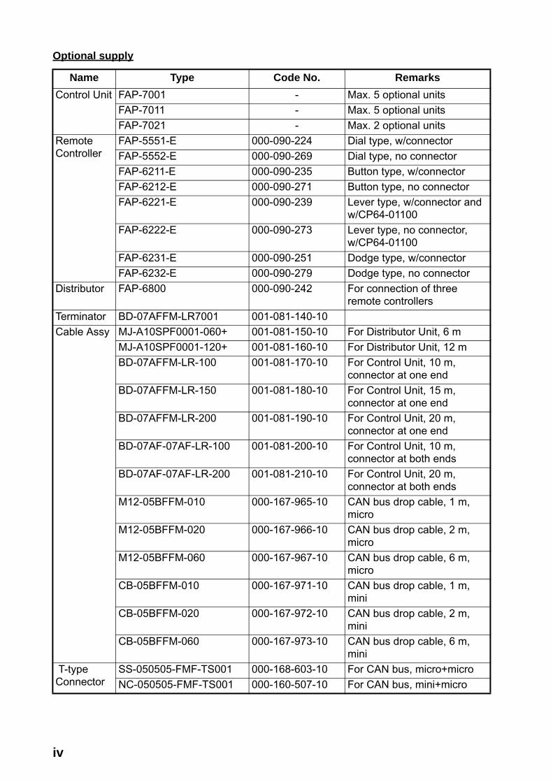
Optional supply
Name Type Code No. RemarksControl Unit FAP-7001 - Max. 5 optional units
FAP-7011 - Max. 5 optional unitsFAP-7021 - Max. 2 optional units
RemoteController
FAP-5551-E 000-090-224 Dial type, w/connectorFAP-5552-E 000-090-269 Dial type, no connectorFAP-6211-E 000-090-235 Button type, w/connectorFAP-6212-E 000-090-271 Button type, no connectorFAP-6221-E 000-090-239 Lever type, w/connector and
w/CP64-01100FAP-6222-E 000-090-273 Lever type, no connector,
w/CP64-01100FAP-6231-E 000-090-251 Dodge type, w/connectorFAP-6232-E 000-090-279 Dodge type, no connector
Distributor FAP-6800 000-090-242 For connection of three remote controllers
Terminator BD-07AFFM-LR7001 001-081-140-10Cable Assy MJ-A10SPF0001-060+ 001-081-150-10 For Distributor Unit, 6 m
MJ-A10SPF0001-120+ 001-081-160-10 For Distributor Unit, 12 mBD-07AFFM-LR-100 001-081-170-10 For Control Unit, 10 m,
connector at one endBD-07AFFM-LR-150 001-081-180-10 For Control Unit, 15 m,
connector at one endBD-07AFFM-LR-200 001-081-190-10 For Control Unit, 20 m,
connector at one endBD-07AF-07AF-LR-100 001-081-200-10 For Control Unit, 10 m,
connector at both endsBD-07AF-07AF-LR-200 001-081-210-10 For Control Unit, 20 m,
connector at both endsM12-05BFFM-010 000-167-965-10 CAN bus drop cable, 1 m,
microM12-05BFFM-020 000-167-966-10 CAN bus drop cable, 2 m,
microM12-05BFFM-060 000-167-967-10 CAN bus drop cable, 6 m,
microCB-05BFFM-010 000-167-971-10 CAN bus drop cable, 1 m,
miniCB-05BFFM-020 000-167-972-10 CAN bus drop cable, 2 m,
miniCB-05BFFM-060 000-167-973-10 CAN bus drop cable, 6 m,
mini T-typeConnector
SS-050505-FMF-TS001 000-168-603-10 For CAN bus, micro+microNC-050505-FMF-TS001 000-160-507-10 For CAN bus, mini+micro

v
TerminationResistor
LTWMC-05BMMT-SL8001 000-168-604-10 For CAN bus, micro, maleLTWMN-05AMMT-SL8001 000-160-508-10 For CAN bus, mini, maleLTWMC-05BFFT-SL8001 000-168-605-10 For CAN bus, micro, femaleLTWMN-05AFFT-SL8001 000-160-509-10 For CAN bus, mini, female
Cable Extension Kit
FAP-7822 000-016-670
Cradle FP64-01411 001-082-770Flush Mount Kit
FAP-7001-FLUSH-KIT 001-082-730 For FAP-7001FAP-7011-FLUSH-KIT 001-082-740 For FAP-7011
Hanger FAP-7001-HANGER 001-082-750 For FAP-7001, w/hanger and two knob bolts
FAP-7011-HANGER 001-082-760 For FAP-7011, w/hanger and two knob bolts
Rudder Reference Unit
FAP-6112-200 - w/20 m cable
Junction Box
FI-5002 000-010-765 w/self-tapping screws
Hanger OP64-2 009-004-030 For FAP-5551/5552Flush Mount Kit
OP64-4 009-005-790 For FAP-6221/6222, panel type
OP64-5 009-005-800 For FAP-6221/6222, surface type
Name Type Code No. Remarks

vi
This page intentionally left blank.

1-1
1. HOW TO INSTALL THE UNITS
1.1 Control Unit FAP-7001/FAP-7011• The Control Unit can be installed three ways:
• Surface mount (fixed from front panel or fixed from rear panel (FAP-7011 only))• Desktop mount, and• Flush mount (Optional kit required, instructions, supplied separately).
Select a mounting location for the Control Unit, keeping the following in mind.
• Select a location with good ventilation.
• Shock and vibration must be the least possible.
• Use the supplied display hard cover when the system is not in use.
• Do not install the display unit under "Plexiglas" or other type of shielding material. Plexi-glas can trap heat and moisture or magnify sunlight energy onto the surface of the dis-play.
• For maintenance and checking purposes, leave space at the sides and rear of the unit and leave slack in cables. See the outline drawing for recommended maintenance space.
• Observe the compass safe distances shown in the safety instructions on page i to pre-vent interference to a magnetic compass.
Control Unit-FAP-7001 Control Unit FAP-7011

1. INSTALLATION
1-2
1.1.1 Surface mountThere are two types of surface mounts: Fasten from front panel and fasten from rear panel (FAP-7011 only).
How to fasten Control Unit from front panel (FAP-7001/FAP-7011)
1. Using the surface mount template at the back of this manual, open a mounting hole in the installation site.
2. Detach the front panel together with the keypad assy. Attach the sponge (supplied) to the rear of display unit.
3. Set the Control Unit to the mounting hole, and fasten the unit with four self-tapping screws (3x20, supplied).
4. Attach the front panel and keypad assy. to the Control Unit.
Sponge
Self-tapping Screw(3x20, 4 pcs.)
Front Panel
Keypad Assy.
Control UnitFAP-7001
Sponge
Front Panel
Self-tapping screw(3x20, 4 pcs.)
Keypad Assy.Control UnitFAP-7011
MountingHoleMountingHole
MountingHoleMountingHole
Remover
1. Set remover to notch on upper side of unit.2. Pull remover to raise panel slightly.3. Similarly use remover to raise panel at lower side. 4. Detach panel with hands.
How to detach front panelProcedure is similar for FAP-7001.

1. INSTALLATION
1-3
How to fasten Control Unit from rear panel (FAP-7011 only)
1. Using the surface mount template at the back of this manual, open a mounting hole in the installation site.
2. Set studs (M3x40, 2 pcs, supplied) in the holes marked in the illustration below. (Use only the studs supplied.)
3. Set the unit to the mounting hole. Fasten the unit with the flat washers, spring washers and wing nuts (supplied).
Insert studhere.
MountingHoleMountingHole
Stud (M3x40)
Wing Nut (M3)
Flat Washer
Spring Washer
1. INSTALLATION
1-4
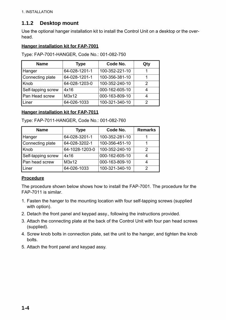
1.1.2 Desktop mountUse the optional hanger installation kit to install the Control Unit on a desktop or the over-head.
Hanger installation kit for FAP-7001
Type: FAP-7001-HANGER, Code No.: 001-082-750
Hanger installation kit for FAP-7011
Type: FAP-7011-HANGER, Code No.: 001-082-760
Procedure
The procedure shown below shows how to install the FAP-7001. The procedure for the FAP-7011 is similar.
1. Fasten the hanger to the mounting location with four self-tapping screws (supplied with option).
2. Detach the front panel and keypad assy., following the instructions provided.
3. Attach the connecting plate at the back of the Control Unit with four pan head screws (supplied).
4. Screw knob bolts in connection plate, set the unit to the hanger, and tighten the knob bolts.
5. Attach the front panel and keypad assy.
Name Type Code No. QtyHanger 64-028-1201-1 100-352-221-10 1Connecting plate 64-028-1201-1 100-356-381-10 1Knob 64-028-1203-0 100-352-240-10 2Self-tapping screw 4x16 000-162-605-10 4Pan Head screw M3x12 000-163-809-10 4Liner 64-026-1033 100-321-340-10 2
Name Type Code No. RemarksHanger 64-028-3201-1 100-352-281-10 1Connecting plate 64-028-3202-1 100-356-451-10 1Knob 64-1028-1203-0 100-352-240-10 2Self-tapping screw 4x16 000-162-605-10 4Pan head screw M3x12 000-163-809-10 4Liner 64-026-1033 100-321-340-10 2

1. INSTALLATION
1-5
6. Attach the hard cover to protect the LCD.
1.2 Processor Unit FAP-7002This unit can be installed on a desktop or on a bulkhead. Select a mounting location con-sidering the following points:
• Install the unit away from direct sunlight and water splash.• Select a location where temperature and humidity are moderate and stable.• Consider the length of the cable connected between the Processor Unit and other
units.• Install the unit where you can easily remove the cover and access controls and connec-
tors.• For the installation on a bulkhead, make sure the mounting location is strong enough to
support the unit under the pitching and rolling normally found on the boat.• To prevent interference, separate the processor unit and its cables at least one meter
from communications equipment, communications antennas and cables for communi-cations equipment.
Pan head screw(M3x12, supplied)Self-tapping screw
(4x16, supplied)
Connecting plate
Knob
Liner
Hanger
1. INSTALLATION
1-6
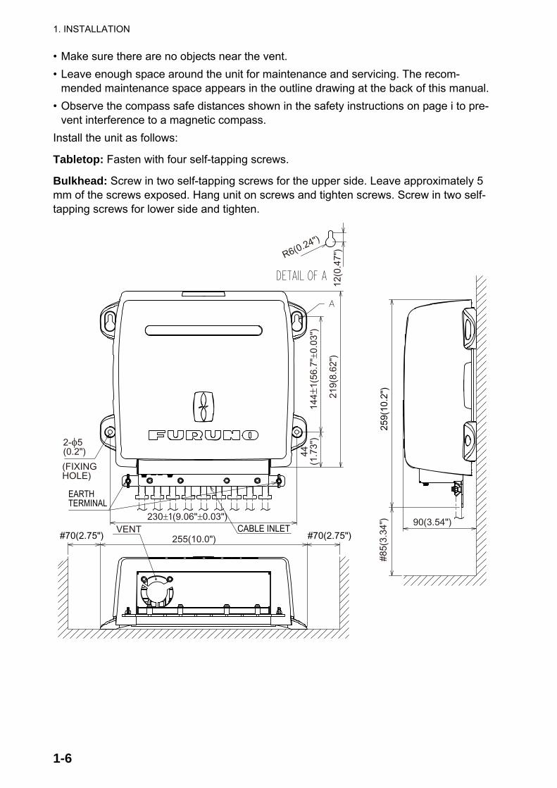
• Make sure there are no objects near the vent.• Leave enough space around the unit for maintenance and servicing. The recom-
mended maintenance space appears in the outline drawing at the back of this manual.• Observe the compass safe distances shown in the safety instructions on page i to pre-
vent interference to a magnetic compass.Install the unit as follows:
Tabletop: Fasten with four self-tapping screws.
Bulkhead: Screw in two self-tapping screws for the upper side. Leave approximately 5 mm of the screws exposed. Hang unit on screws and tighten screws. Screw in two self-tapping screws for lower side and tighten.
259(
10.2
")
90(3.54")
#85(
3.34
")
CABLE INLET
144±
1(56
.7"±
0.03
")
219(
8.62
")
VENT#70(2.75") 255(10.0")
230±1(9.06"±0.03")
EARTHTERMINAL
(FIXINGHOLE)
2-φ5(0.2") 44
(1.7
3")
12(0
.47"
)
R6(0.24")
#70(2.75")
1. INSTALLATION
1-7
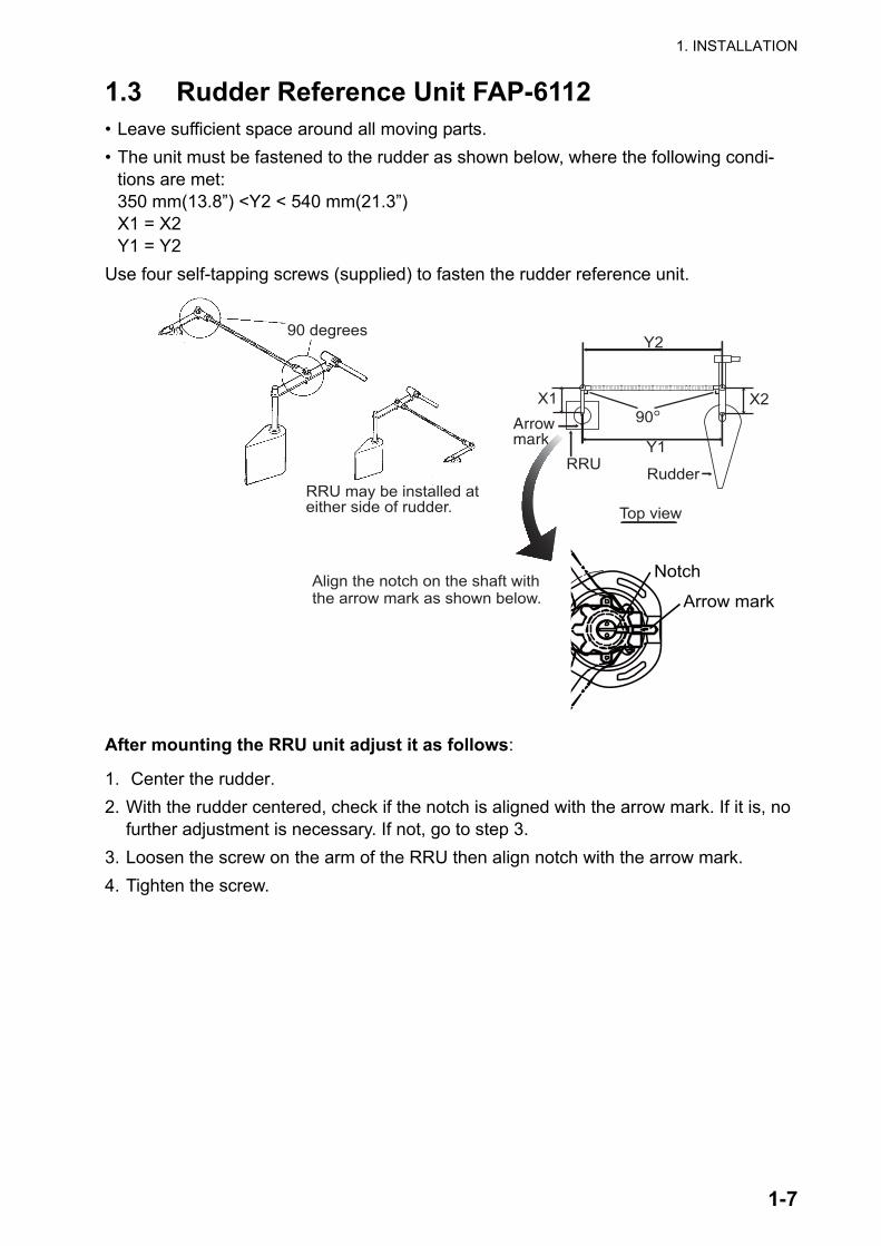
1.3 Rudder Reference Unit FAP-6112• Leave sufficient space around all moving parts.• The unit must be fastened to the rudder as shown below, where the following condi-
tions are met: 350 mm(13.8”) <Y2 < 540 mm(21.3”)X1 = X2Y1 = Y2
Use four self-tapping screws (supplied) to fasten the rudder reference unit.
After mounting the RRU unit adjust it as follows:
1. Center the rudder.2. With the rudder centered, check if the notch is aligned with the arrow mark. If it is, no
further adjustment is necessary. If not, go to step 3.3. Loosen the screw on the arm of the RRU then align notch with the arrow mark.4. Tighten the screw.
X1 X2
Y1
Y2
90°
Top view
Arrowmark
RRU Rudder
Arrow mark
Notch
90 degrees
RRU may be installed ateither side of rudder.
Align the notch on the shaft withthe arrow mark as shown below.
1. INSTALLATION
1-8
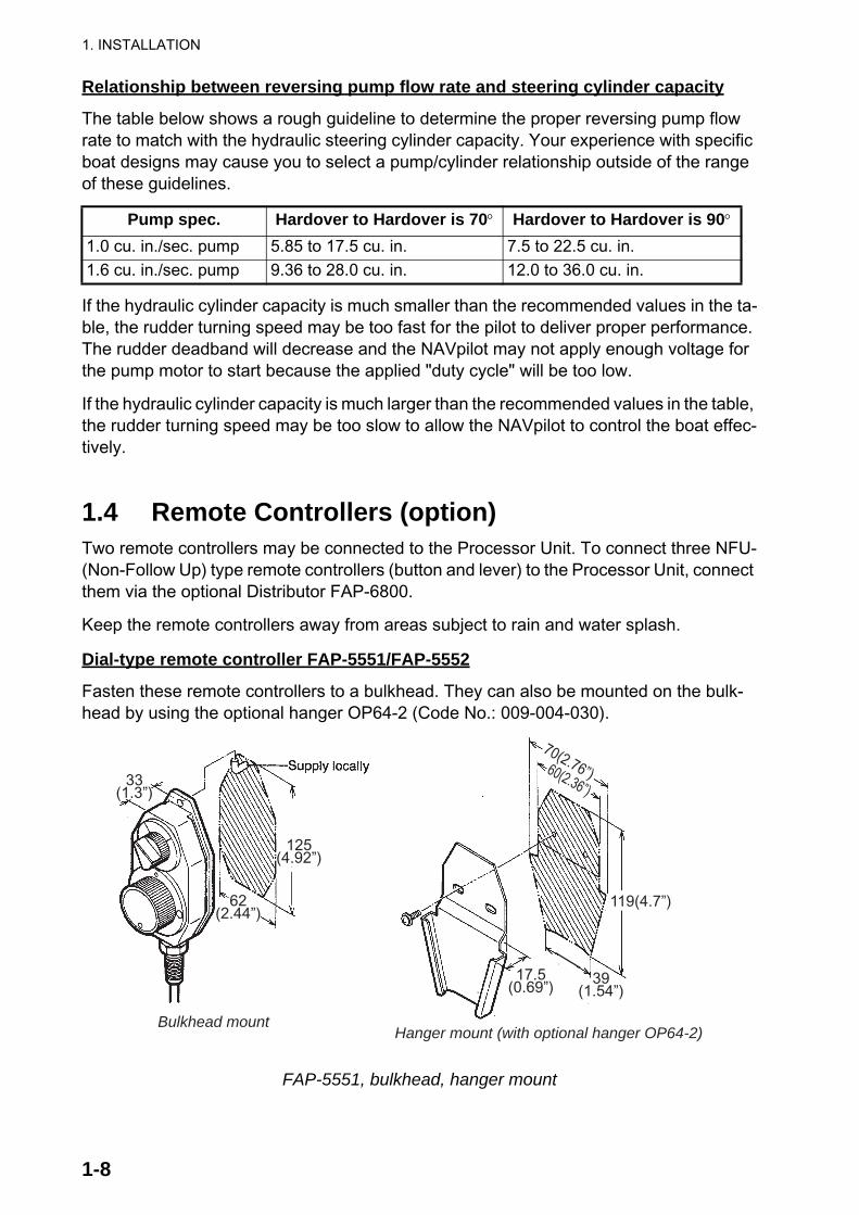
Relationship between reversing pump flow rate and steering cylinder capacity
The table below shows a rough guideline to determine the proper reversing pump flow rate to match with the hydraulic steering cylinder capacity. Your experience with specific boat designs may cause you to select a pump/cylinder relationship outside of the range of these guidelines.
If the hydraulic cylinder capacity is much smaller than the recommended values in the ta-ble, the rudder turning speed may be too fast for the pilot to deliver proper performance. The rudder deadband will decrease and the NAVpilot may not apply enough voltage for the pump motor to start because the applied "duty cycle" will be too low.
If the hydraulic cylinder capacity is much larger than the recommended values in the table, the rudder turning speed may be too slow to allow the NAVpilot to control the boat effec-tively.
1.4 Remote Controllers (option)Two remote controllers may be connected to the Processor Unit. To connect three NFU-(Non-Follow Up) type remote controllers (button and lever) to the Processor Unit, connect them via the optional Distributor FAP-6800.
Keep the remote controllers away from areas subject to rain and water splash.
Dial-type remote controller FAP-5551/FAP-5552
Fasten these remote controllers to a bulkhead. They can also be mounted on the bulk-head by using the optional hanger OP64-2 (Code No.: 009-004-030).
FAP-5551, bulkhead, hanger mount
Pump spec. Hardover to Hardover is 70° Hardover to Hardover is 90°
1.0 cu. in./sec. pump 5.85 to 17.5 cu. in. 7.5 to 22.5 cu. in.1.6 cu. in./sec. pump 9.36 to 28.0 cu. in. 12.0 to 36.0 cu. in.
Bulkhead mountHanger mount (with optional hanger OP64-2)
70(2.76”)60(2.36”)
119(4.7”)
39(1.54”)
17.5(0.69”)
125(4.92”)
62(2.44”)
33(1.3”)
1. INSTALLATION
1-9
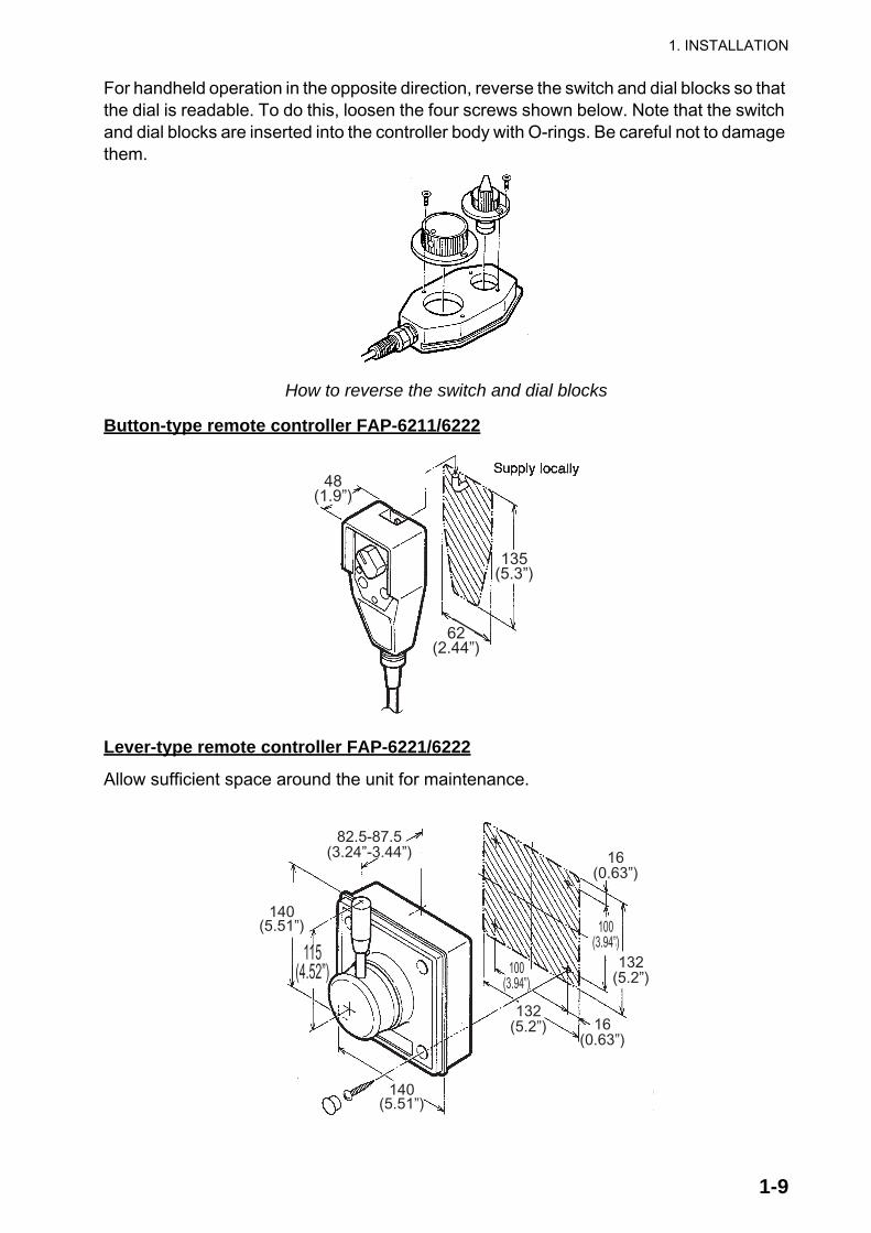
For handheld operation in the opposite direction, reverse the switch and dial blocks so that the dial is readable. To do this, loosen the four screws shown below. Note that the switch and dial blocks are inserted into the controller body with O-rings. Be careful not to damage them.
How to reverse the switch and dial blocks
Button-type remote controller FAP-6211/6222
Lever-type remote controller FAP-6221/6222
Allow sufficient space around the unit for maintenance.
48(1.9”)
135(5.3”)
62(2.44”)
140(5.51”)
140(5.51”)
115(4.52”)
82.5-87.5(3.24”-3.44”) 16
(0.63”)
100(3.94”)
132(5.2”)
100(3.94”)
132(5.2”) 16
(0.63”)

1. INSTALLATION
1-10
To mount the FAP-6221/6212 in a panel, the optional flush mount kit OP64-4 or OP64-5 is required.
Flush mount kit OP64-4 (Code no. 009-005-790)
Flush mount kit OP64-5 (Code no. 009-005-800)
How to flush mount the FAP-6221 with flush mount kit OP64-4
Name Type Code No. QtyPanel frame OP64-4 009-006-170 1Rubber ring 64-015-4524 100-145-111-10 1Hex. nut M4 000-167-488-10 4Flat washer M4 000-167-455-10 4Spring washer M4 000-167-405-10 4
Name Type Code No. QtyFixing plate OP64-5 009-006-200 1Rubber ring 64-015-4524 100-145-111-10 1Hex. nut M4 000-167-488-10 4Spring washer M4 000-167-405-10 4Hex. bolt M4x35 000-162-861-10 4
140(5.51”)
6.50.26”
MAX.25(0.98”)
150(5.9”)
137(5.4”)
147(5.8”)
150(5.9”)
1.5(0.06”)
Flat washerSpring washerHex. nut
Panel frame
Rubber ring

1. INSTALLATION
1-11
How to flush mount the FAP-6221 with flush mount kit OP64-5
1.5 Distributor FAP-6800 (option)Use the Distributor to connect three Non-Follow Up-type remote controllers to the Proces-sor Unit. Fix the unit to the mounting location with wood screws. For added support, use nuts, bolts and washers (all local supply) instead of the wood screws.
135(5.3”)
135(5.3”)
MAX.25(0.98”)
Hex. bolt
Spring washerHex. nut
Fixing plate
Pan head screwM3x20(local supply)
Rubber ring
60(2.36”)
37(1.46”)
172(6.77”)60(2.36”)
8(0.3”)
156(6.14”)172(6.77”)
1. INSTALLATION
1-12
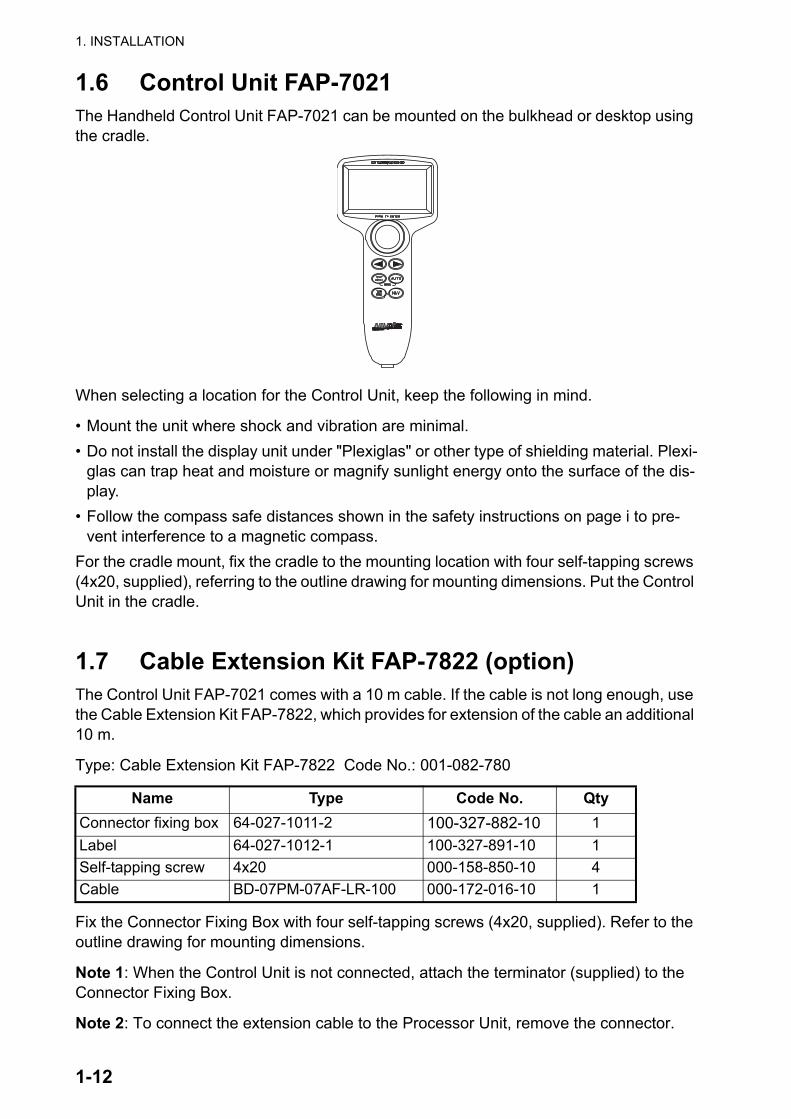
1.6 Control Unit FAP-7021The Handheld Control Unit FAP-7021 can be mounted on the bulkhead or desktop using the cradle.
When selecting a location for the Control Unit, keep the following in mind.
• Mount the unit where shock and vibration are minimal.• Do not install the display unit under "Plexiglas" or other type of shielding material. Plexi-
glas can trap heat and moisture or magnify sunlight energy onto the surface of the dis-play.
• Follow the compass safe distances shown in the safety instructions on page i to pre-vent interference to a magnetic compass.
For the cradle mount, fix the cradle to the mounting location with four self-tapping screws (4x20, supplied), referring to the outline drawing for mounting dimensions. Put the Control Unit in the cradle.
1.7 Cable Extension Kit FAP-7822 (option)The Control Unit FAP-7021 comes with a 10 m cable. If the cable is not long enough, use the Cable Extension Kit FAP-7822, which provides for extension of the cable an additional 10 m.
Type: Cable Extension Kit FAP-7822 Code No.: 001-082-780
Fix the Connector Fixing Box with four self-tapping screws (4x20, supplied). Refer to the outline drawing for mounting dimensions.
Note 1: When the Control Unit is not connected, attach the terminator (supplied) to the Connector Fixing Box.
Note 2: To connect the extension cable to the Processor Unit, remove the connector.
Name Type Code No. QtyConnector fixing box 64-027-1011-2 100-327-882-10 1Label 64-027-1012-1 100-327-891-10 1Self-tapping screw 4x20 000-158-850-10 4Cable BD-07PM-07AF-LR-100 000-172-016-10 1
2-1
2. WIRING
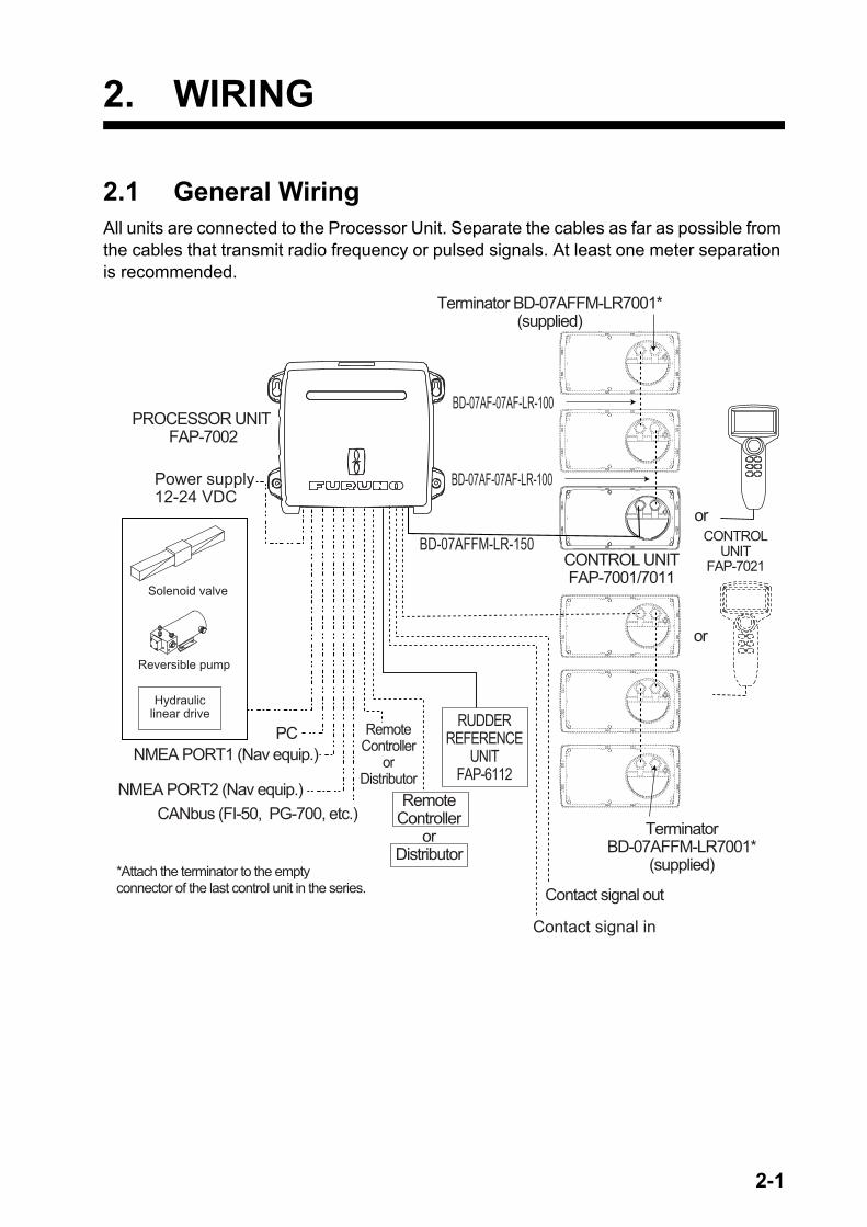
2.1 General WiringAll units are connected to the Processor Unit. Separate the cables as far as possible from the cables that transmit radio frequency or pulsed signals. At least one meter separation is recommended.
Reversible pump
Solenoid valve
Hydrauliclinear drive
Power supply12-24 VDC
Terminator BD-07AFFM-LR7001*(supplied)
CONTROL UNITFAP-7001/7011
PROCESSOR UNIT FAP-7002
RUDDERREFERENCE
UNITFAP-6112
RemoteController
orDistributor
RemoteController
orDistributor
PCNMEA PORT1 (Nav equip.)
NMEA PORT2 (Nav equip.)CANbus (FI-50, PG-700, etc.)
*Attach the terminator to the emptyconnector of the last control unit in the series.
or
or
CONTROLUNIT
FAP-7021
BD-07AF-07AF-LR-100
BD-07AF-07AF-LR-100
TerminatorBD-07AFFM-LR7001*
(supplied)
BD-07AFFM-LR-150
Contact signal out
Contact signal in
2. WIRING
2-2
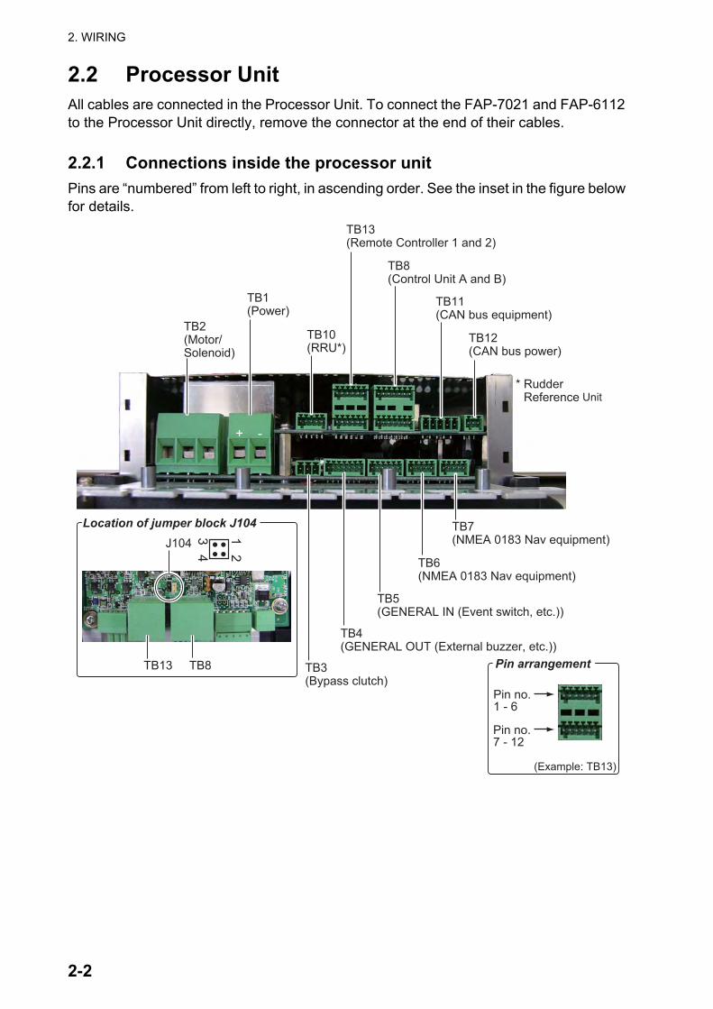
2.2 Processor UnitAll cables are connected in the Processor Unit. To connect the FAP-7021 and FAP-6112 to the Processor Unit directly, remove the connector at the end of their cables.
2.2.1 Connections inside the processor unitPins are “numbered” from left to right, in ascending order. See the inset in the figure below for details.
TB1(Power)
TB2(Motor/Solenoid)
TB10(RRU*)
TB13(Remote Controller 1 and 2)
TB8(Control Unit A and B)
TB11(CAN bus equipment)
TB12(CAN bus power)
TB3(Bypass clutch)
TB4(GENERAL OUT (External buzzer, etc.))
TB7(NMEA 0183 Nav equipment)
TB6(NMEA 0183 Nav equipment)
TB5(GENERAL IN (Event switch, etc.))
12
34J104
TB13 TB8
Location of jumper block J104
* Rudder Reference Unit
+ -
(Example: TB13)
Pin arrangement
Pin no.1 - 6
Pin no.7 - 12

2. WIRING
2-3
2.2.2 How to fasten cables to the cable clampsFasten the cables to the processor unit as shown below. There is no specified order to fasten the cables.
1. Remove the outside cover:
1) Hold the right and left sides of the cover.2) Pull the cover outward and lift to remove.
2. Remove the four screws marked with circles in the figure shown below.
3. Separate the cable clamp/fan assy from the shield cover as shown in the figure below. Open the assembly carefully to prevent damage to the cable connected to the fan.
4. Disconnect the fan connector.
5. Twist cable cores then put the cores into their correct connector blocks. (See the next page for how to put wires into a connector block.)
6. For the NMEA cable, wind vinyl tape around the cable cores.
Cable clamp/fan assy.
Shield cover
Disconnectthis connector.
2. WIRING
2-4
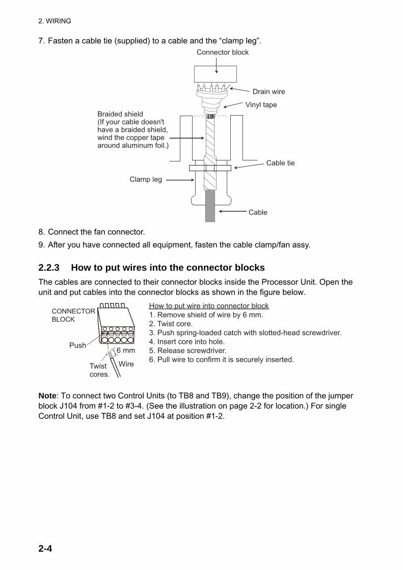
7. Fasten a cable tie (supplied) to a cable and the “clamp leg”.
8. Connect the fan connector.
9. After you have connected all equipment, fasten the cable clamp/fan assy.
2.2.3 How to put wires into the connector blocksThe cables are connected to their connector blocks inside the Processor Unit. Open the unit and put cables into the connector blocks as shown in the figure below.
Note: To connect two Control Units (to TB8 and TB9), change the position of the jumper block J104 from #1-2 to #3-4. (See the illustration on page 2-2 for location.) For single Control Unit, use TB8 and set J104 at position #1-2.
Clamp leg
Cable
Cable tie
Braided shield(If your cable doesn't have a braided shield, wind the copper tape around aluminum foil.)
Drain wire
Vinyl tape
Connector block
How to put wire into connector block1. Remove shield of wire by 6 mm.2. Twist core.3. Push spring-loaded catch with slotted-head screwdriver.4. Insert core into hole.5. Release screwdriver.6. Pull wire to confirm it is securely inserted.
CONNECTORBLOCK
Push
Twistcores.
Wire
6 mm

2. WIRING
2-5
2.2.4 Power and motor cablesFor the power cable and motor line cable, see the table below to select cables. Connect the power cable to a breaker that has a rating acceptable to the motor.
• The thickness of the cables varies with the rated current of the motor. The table shows the specifications for 25A motor.
• Use single core wire or stranded wire. (For stranded wire the max. no of wires is seven).
• Do not twist cores to prevent them from disconnecting.
How to connect a reversible pump
Cablelength Motor voltage
12 VDC 24 VDCSection of core(mm2)
AWG Section of core(mm2)
AWG
3 m or less 2.5 12 2.5 126 m or less 4 10 2.5 1210 m or less 6 8 4 1016 m or less 10 6 6 8
Reversible pump
MOTOR A+ MOTOR B- GND POWER + POWER -SOL A SOL B
TB1TB2
2. WIRING
2-6
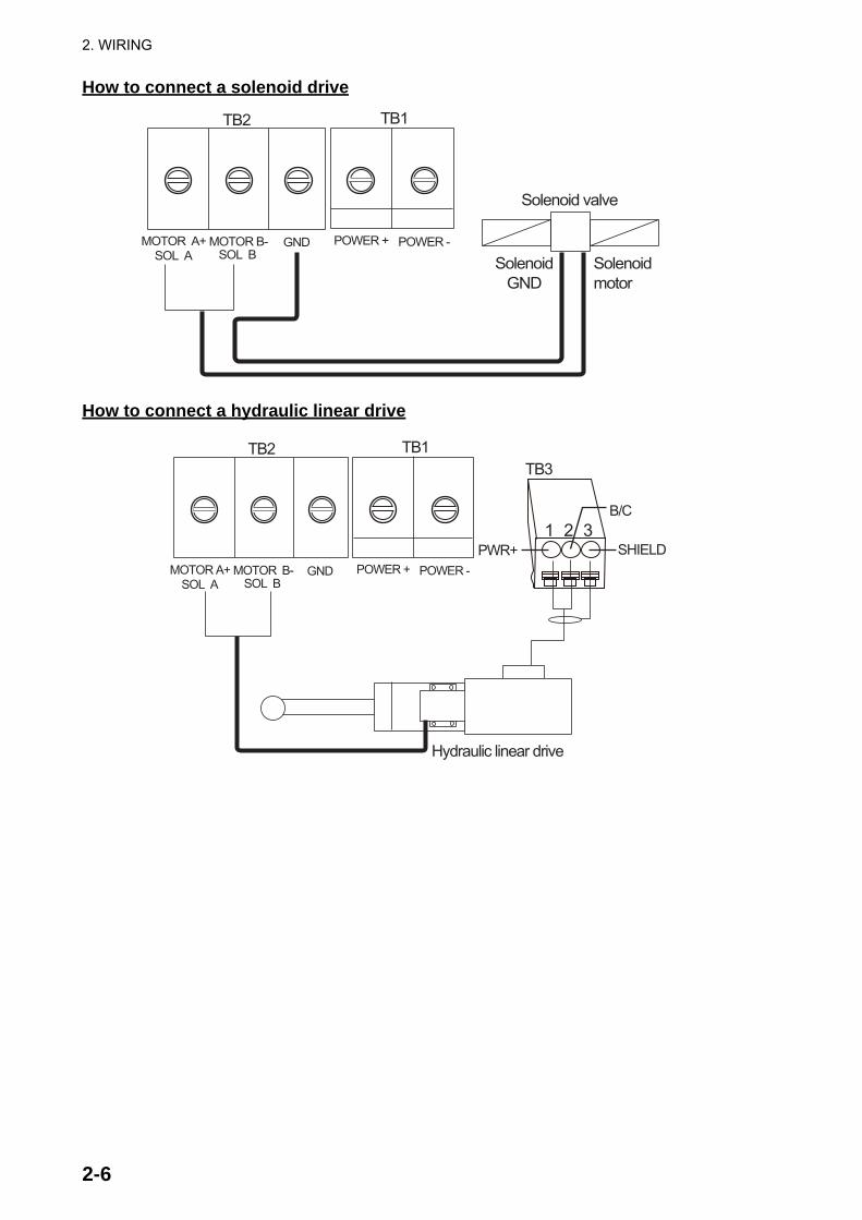
How to connect a solenoid drive
How to connect a hydraulic linear drive
Solenoidmotor
SolenoidGND
Solenoid valve
MOTOR A+ MOTOR B- GND POWER + POWER -SOL A SOL B
TB1TB2
Hydraulic linear drive
TB3
PWR+
B/C
SHIELDMOTOR A+ MOTOR B- GND POWER + POWER -
SOL A SOL B
TB1TB2
1 2 3
2. WIRING
2-7
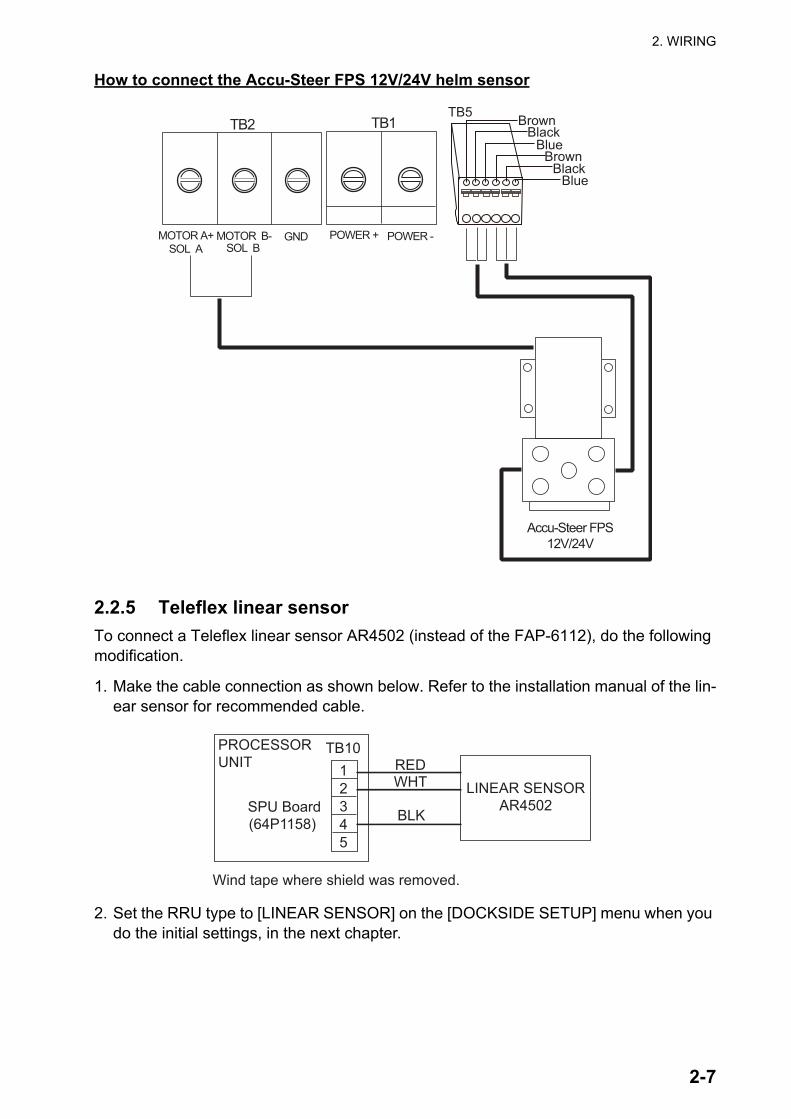
How to connect the Accu-Steer FPS 12V/24V helm sensor
2.2.5 Teleflex linear sensorTo connect a Teleflex linear sensor AR4502 (instead of the FAP-6112), do the following modification.
1. Make the cable connection as shown below. Refer to the installation manual of the lin-ear sensor for recommended cable.
2. Set the RRU type to [LINEAR SENSOR] on the [DOCKSIDE SETUP] menu when you do the initial settings, in the next chapter.
MOTOR A+ MOTOR B- GND POWER + POWER -SOL A SOL B
TB1TB2
Accu-Steer FPS12V/24V
BrownBlack
BlueBrown
BlackBlue
TB5
12345
SPU Board(64P1158)
TB10
LINEAR SENSORAR4502
REDWHT
BLK
PROCESSORUNIT
Wind tape where shield was removed.
2. WIRING
2-8
2.2.6 CAN bus powerThe maximum current that can be supplied to the CAN bus network is 1A. Use a “floating power supply” and make sure it meets with CAN bus (NMEA 2000) regulations.
For complete information about CAN bus wiring, see the “Furuno CAN bus Network De-sign Guide (TIE-00170-*)” on Tech-Net.
2.2.7 Connection to TB4TB4 is for contact relay output. The No.1 line is Normal Open, and the No.3 line is Normal Close. For Active Close, use Normal Open; for Active Open use Normal Close. The rated current of the contact is 3A. The maximum acceptable open-close is 50VA.
2.3 Control UnitFAP-7001/FAP-7011
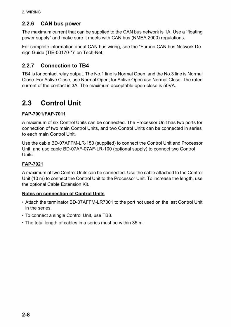
A maximum of six Control Units can be connected. The Processor Unit has two ports for connection of two main Control Units, and two Control Units can be connected in series to each main Control Unit.
Use the cable BD-07AFFM-LR-150 (supplied) to connect the Control Unit and Processor Unit, and use cable BD-07AF-07AF-LR-100 (optional supply) to connect two Control Units.
FAP-7021
A maximum of two Control Units can be connected. Use the cable attached to the Control Unit (10 m) to connect the Control Unit to the Processor Unit. To increase the length, use the optional Cable Extension Kit.
Notes on connection of Control Units
• Attach the terminator BD-07AFFM-LR7001 to the port not used on the last Control Unit in the series.
• To connect a single Control Unit, use TB8.• The total length of cables in a series must be within 35 m.
2. WIRING
2-9
• FAP-7021 can be connected at the end of FAP-7001/FAP-7011 Control Unit.
2.4 Remote Controllers (option)The Processor Unit has two ports for connection of two remote controllers.
The Distributor FAP-6800 allows you to connect three NFU (Non Follow-Up) type remote controllers to the Processor Unit.
Note 1: Connect remote controllers that have connectors to the Distributor FAP-6800.
Note 2: Set the remote controller type on the [SYSTEM SETUP] menu, in chapter 3.
Remote controllers with connector Remote controller without connectorFAP-5551 (dial), FAP-6211 (button),FAP-6221 (lever), FAP-6231 (dodge)
FAP-5552 (dial), FAP-6212 (button), FAP-6222 (lever), FAP-6232 (dodge)
PROCESSOR UNIT
BD-07AFFM-LR-150
BD-07AF-07AF-LR-100BD-07AF-07AF-LR-100
PROCESSOR UNIT
FAP-7001/7011 FAP-7021
BD-07AF-07AF-LR-100BD-07AF-07AF-LR-100
Termi-nator
TB8M
ax. c
able
leng
th 3
5 m
BD-07AFFM-LR-150
2. WIRING
2-10
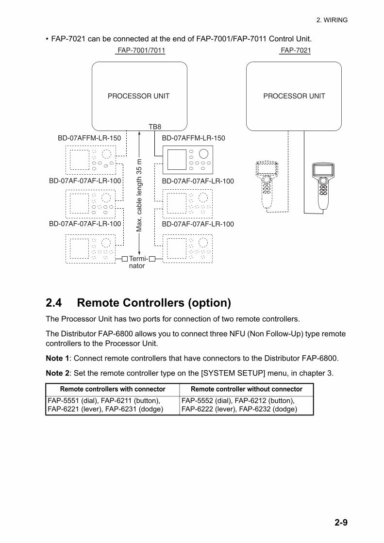
2.4.1 Example remote controller connections
No distributor
Connect any two remote controllers.
Dial-type remote controller
The distributor cannot be used with the dial-type remote controller.
Button- or lever-type remote controller with distributor
Connect a maximum of six button- or lever-type remote controllers.
Dodge-type remote controller with distributor
Connect a maximum of six dodge-type remote controllers.
FAP-5552, FAP-6212, or FAP-6222
PROCESSOR UNITFAP-5552, FAP-6212, or FAP-6222
FAP-5552 (dial)
PROCESSOR UNIT
FAP-5552 (dial)
FAP-6211 (button)/6221 (lever)
PROCESSOR UNIT
FAP-6211 (button)/6221 (lever)FAP-6211 (button)/6221 (lever)
FAP-6211 (button)/6221 (lever)FAP-6211 (button)/6221 (lever)FAP-6211 (button)/6221 (lever)
FAP-6231 (dodge type)
PROCESSOR UNIT
FAP-6231 (dodge type)FAP-6231 (dodge type)
FAP-6231 (dodge type)FAP-6231 (dodge type)FAP-6231 (dodge type)
2. WIRING
2-11
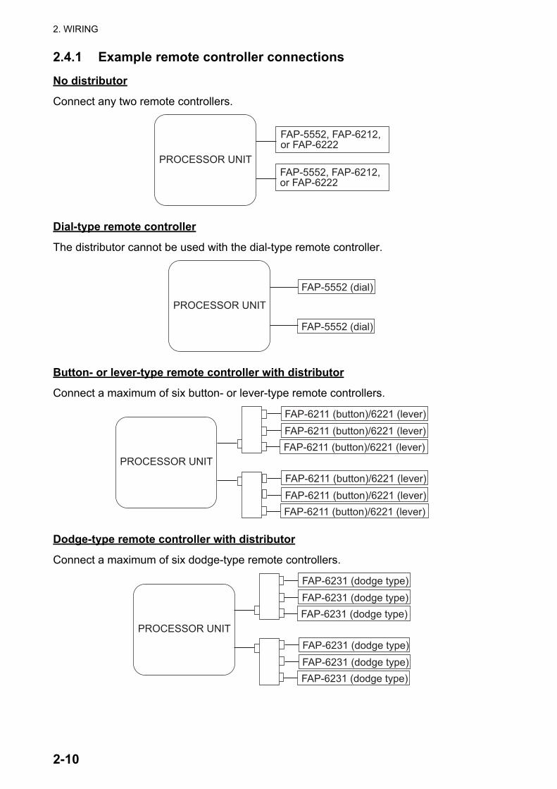
2.4.2 Prohibited remote controller connectionsThe remote controller combinations shown in this section are not allowed.
Wrong connection no.1
You cannot connect different types of remote controllers.
Wrong connection no.2
Connect only one dial-type remote controller.
Wrong connection no.3
You cannot connect multiple distributors.
FAP-6211 (button)
PROCESSOR UNIT
FAP-6221 (lever)FAP-6231 (dodge)
FAP-6211 (button)FAP-6221 (lever)FAP-6231 (dodge)
FAP-5551 (dial)
PROCESSOR UNIT
FAP-5551 (dial)
FAP-5551 (dial)FAP-5551 (dial)
PROCESSOR UNIT
2. WIRING
2-12
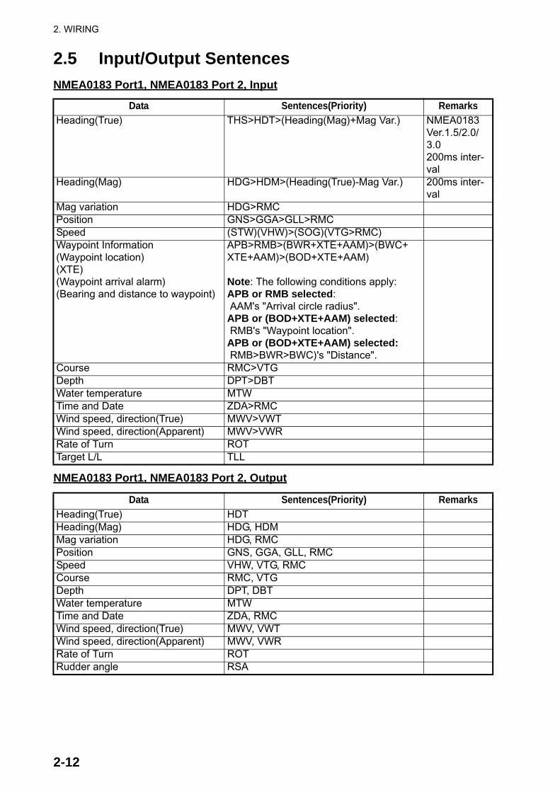
2.5 Input/Output SentencesNMEA0183 Port1, NMEA0183 Port 2, Input
NMEA0183 Port1, NMEA0183 Port 2, Output
Data Sentences(Priority) RemarksHeading(True) THS>HDT>(Heading(Mag)+Mag Var.) NMEA0183
Ver.1.5/2.0/3.0200ms inter-val
Heading(Mag) HDG>HDM>(Heading(True)-Mag Var.) 200ms inter-val
Mag variation HDG>RMCPosition GNS>GGA>GLL>RMCSpeed (STW)(VHW)>(SOG)(VTG>RMC)Waypoint Information(Waypoint location)(XTE)(Waypoint arrival alarm)(Bearing and distance to waypoint)
APB>RMB>(BWR+XTE+AAM)>(BWC+XTE+AAM)>(BOD+XTE+AAM)
Note: The following conditions apply:APB or RMB selected: AAM's "Arrival circle radius".APB or (BOD+XTE+AAM) selected: RMB's "Waypoint location". APB or (BOD+XTE+AAM) selected: RMB>BWR>BWC)'s "Distance".
Course RMC>VTGDepth DPT>DBTWater temperature MTWTime and Date ZDA>RMCWind speed, direction(True) MWV>VWTWind speed, direction(Apparent) MWV>VWRRate of Turn ROTTarget L/L TLL
Data Sentences(Priority) RemarksHeading(True) HDTHeading(Mag) HDG, HDMMag variation HDG, RMCPosition GNS, GGA, GLL, RMCSpeed VHW, VTG, RMCCourse RMC, VTGDepth DPT, DBTWater temperature MTWTime and Date ZDA, RMCWind speed, direction(True) MWV, VWTWind speed, direction(Apparent) MWV, VWRRate of Turn ROTRudder angle RSA
2. WIRING
2-13
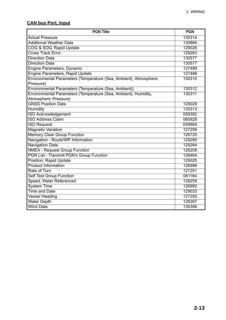
CAN bus Port, Input
PGN Title PGNActual Pressure 130314Additional Weather Data 130880COG & SOG, Rapid Update 129026Cross Track Error 129283Direction Data 130577Direction Data 130577Engine Parameters, Dynamic 127489Engine Parameters, Rapid Update 127488Environmental Parameters (Temperature (Sea, Ambient), AtmosphericPressure)
130310
Environmental Parameters (Temperature (Sea, Ambient)) 130312Environmental Parameters (Temperature (Sea, Ambient), Humidity,Atmospheric Pressure)
130311
GNSS Position Data 129029Humidity 130313ISO Acknowledgement 059392ISO Address Claim 060928ISO Request 059904Magnetic Variation 127258Memory Clear Group Function 126720Navigation - Route/WP Information 129285Navigation Data 129284NMEA - Request Group Function 126208PGN List - Transmit PGN’s Group Function 126464Position, Rapid Update 129025Product Information 126996Rate of Turn 127251Self Test Group Function 061184Speed, Water Referenced 128259System Time 126992Time and Date 129033Vessel Heading 127250Water Depth 128267Wind Data 130306
2. WIRING
2-14
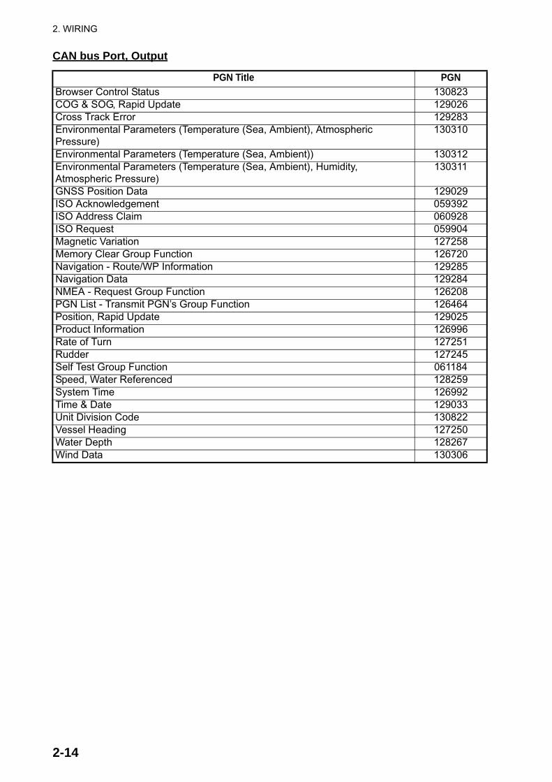
CAN bus Port, Output
PGN Title PGNBrowser Control Status 130823COG & SOG, Rapid Update 129026Cross Track Error 129283Environmental Parameters (Temperature (Sea, Ambient), AtmosphericPressure)
130310
Environmental Parameters (Temperature (Sea, Ambient)) 130312Environmental Parameters (Temperature (Sea, Ambient), Humidity,Atmospheric Pressure)
130311
GNSS Position Data 129029ISO Acknowledgement 059392ISO Address Claim 060928ISO Request 059904Magnetic Variation 127258Memory Clear Group Function 126720Navigation - Route/WP Information 129285Navigation Data 129284NMEA - Request Group Function 126208PGN List - Transmit PGN’s Group Function 126464Position, Rapid Update 129025Product Information 126996Rate of Turn 127251Rudder 127245Self Test Group Function 061184Speed, Water Referenced 128259System Time 126992Time & Date 129033Unit Division Code 130822Vessel Heading 127250Water Depth 128267Wind Data 130306
3-1
3. INITIAL SETTINGS
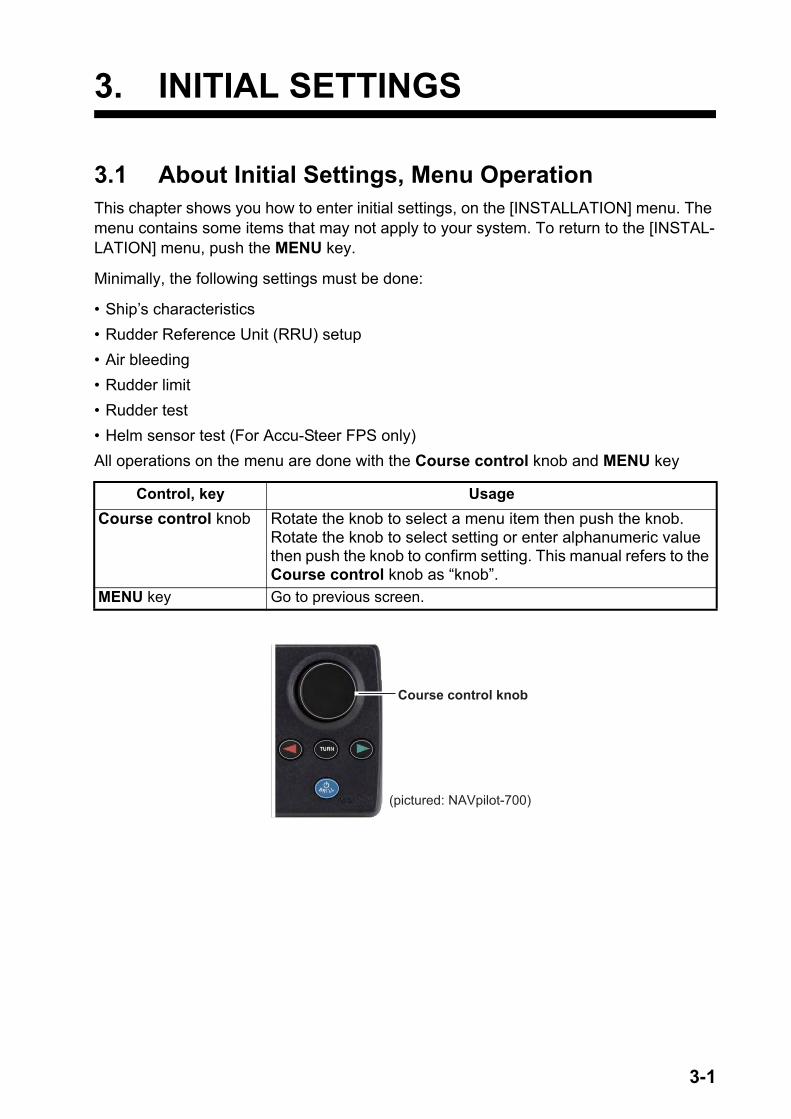
3.1 About Initial Settings, Menu OperationThis chapter shows you how to enter initial settings, on the [INSTALLATION] menu. The menu contains some items that may not apply to your system. To return to the [INSTAL-LATION] menu, push the MENU key.
Minimally, the following settings must be done:
• Ship’s characteristics• Rudder Reference Unit (RRU) setup• Air bleeding • Rudder limit• Rudder test• Helm sensor test (For Accu-Steer FPS only)All operations on the menu are done with the Course control knob and MENU key
Control, key UsageCourse control knob Rotate the knob to select a menu item then push the knob.
Rotate the knob to select setting or enter alphanumeric value then push the knob to confirm setting. This manual refers to the Course control knob as “knob”.
MENU key Go to previous screen.
Course control knob
(pictured: NAVpilot-700)
3. INITIAL SETTINGS
3-2
3.2 How to Select Language and Units, Open the Installation Menu
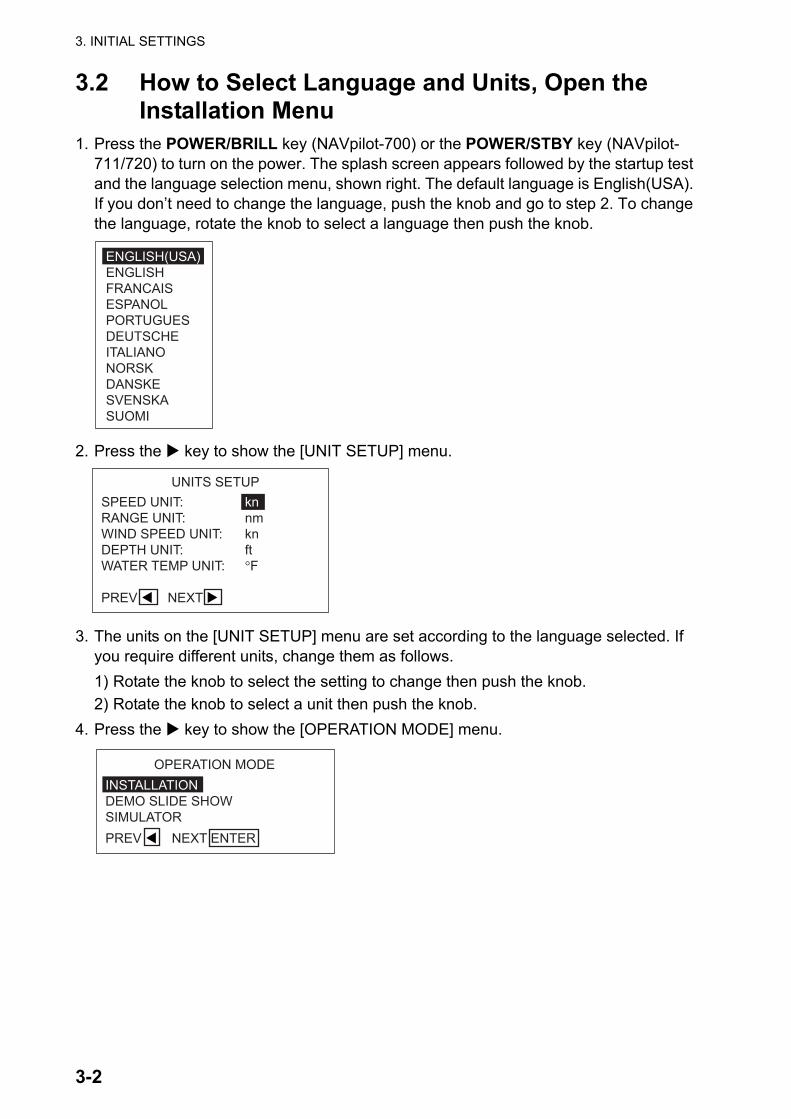
1. Press the POWER/BRILL key (NAVpilot-700) or the POWER/STBY key (NAVpilot-711/720) to turn on the power. The splash screen appears followed by the startup test and the language selection menu, shown right. The default language is English(USA). If you don’t need to change the language, push the knob and go to step 2. To change the language, rotate the knob to select a language then push the knob.
2. Press the key to show the [UNIT SETUP] menu.
3. The units on the [UNIT SETUP] menu are set according to the language selected. If you require different units, change them as follows.1) Rotate the knob to select the setting to change then push the knob.2) Rotate the knob to select a unit then push the knob.
4. Press the key to show the [OPERATION MODE] menu.
ENGLISH(USA)ENGLISHFRANCAISESPANOLPORTUGUESDEUTSCHEITALIANONORSKDANSKESVENSKASUOMI
UNITS SETUP SPEED UNIT: knRANGE UNIT: nmWIND SPEED UNIT: knDEPTH UNIT: ftWATER TEMP UNIT: °F
PREV � NEXT �
OPERATION MODE INSTALLATIONDEMO SLIDE SHOWSIMULATORPREV � NEXT ENTER
3. INITIAL SETTINGS
3-3
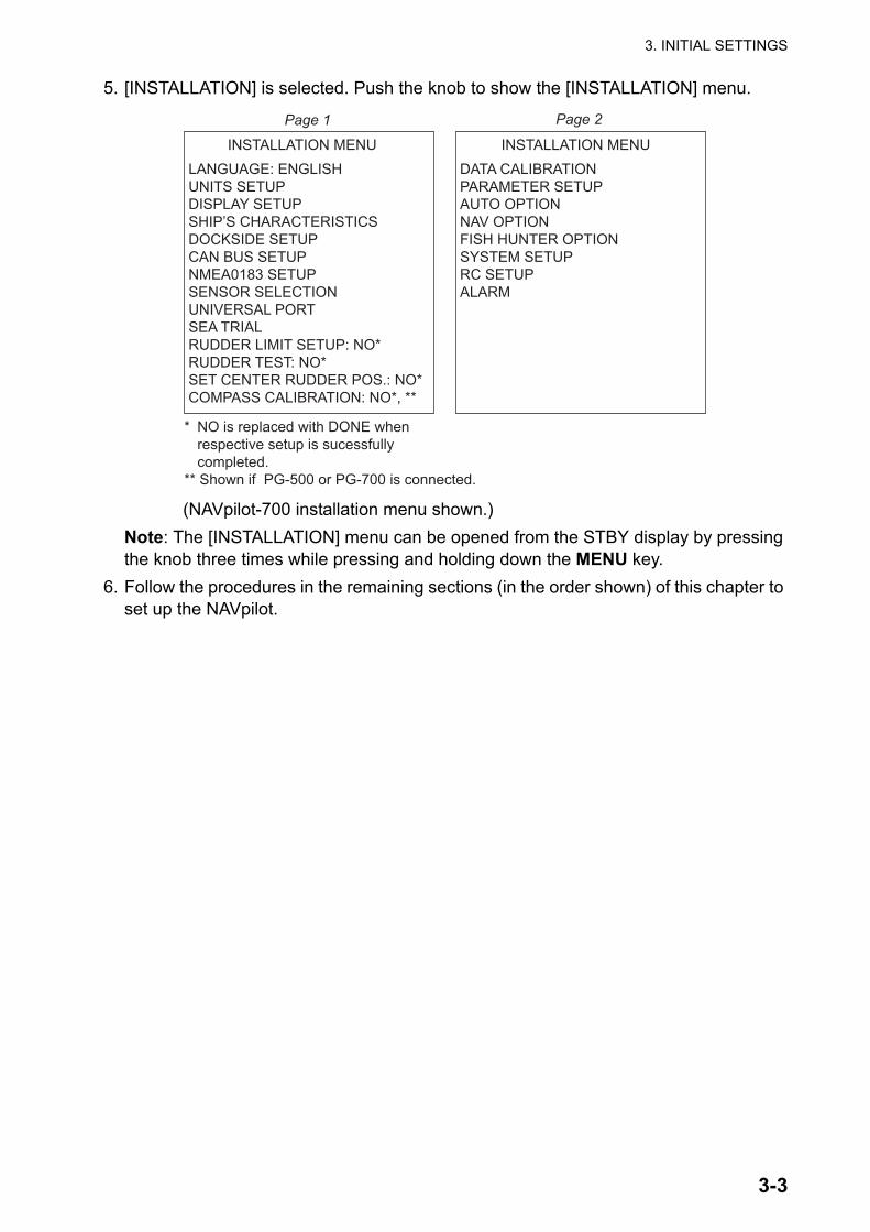
5. [INSTALLATION] is selected. Push the knob to show the [INSTALLATION] menu.
(NAVpilot-700 installation menu shown.)Note: The [INSTALLATION] menu can be opened from the STBY display by pressing the knob three times while pressing and holding down the MENU key.
6. Follow the procedures in the remaining sections (in the order shown) of this chapter to set up the NAVpilot.
INSTALLATION MENU LANGUAGE: ENGLISH
UNITS SETUPDISPLAY SETUPSHIP’S CHARACTERISTICSDOCKSIDE SETUPCAN BUS SETUPNMEA0183 SETUPSENSOR SELECTIONUNIVERSAL PORTSEA TRIALRUDDER LIMIT SETUP: NO*RUDDER TEST: NO*SET CENTER RUDDER POS.: NO*COMPASS CALIBRATION: NO*, **
* NO is replaced with DONE when respective setup is sucessfully completed.** Shown if PG-500 or PG-700 is connected.
Page 1
DATA CALIBRATION
PARAMETER SETUPAUTO OPTIONNAV OPTIONFISH HUNTER OPTIONSYSTEM SETUPRC SETUPALARM
Page 2
INSTALLATION MENU
3. INITIAL SETTINGS
3-4
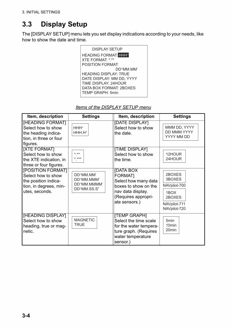
3.3 Display SetupThe [DISPLAY SETUP] menu lets you set display indications according to your needs, like how to show the date and time.
Items of the DISPLAY SETUP menu
Item, description Settings Item, description Settings[HEADING FORMAT]Select how to show the heading indica-tion, in three or four figures.
[DATE DISPLAY]Select how to show the date.
[XTE FORMAT]Select how to show the XTE indication, in three or four figures.
[TIME DISPLAY]Select how to show the time.
[POSITION FORMAT]Select how to show the position indica-tion, in degrees, min-utes, seconds.
[DATA BOXFORMAT]Select how many data boxes to show on the nav data display. (Requires appropri-ate sensors.)
[HEADING DISPLAY]Select how to show heading, true or mag-netic.
[TEMP GRAPH]Select the time scale for the water tempera-ture graph. (Requires water temperature sensor.)
DISPLAY SETUP HEADING FORMAT: HHH°XTE FORMAT: *.**POSITION FORMAT: DD°MM.MM’HEADING DISPLAY: TRUEDATE DISPLAY: MM DD, YYYYTIME DISPLAY: 24HOURDATA BOX FORMAT: 2BOXESTEMP GRAPH: 5min
HHH°HHH.H°
MMM DD, YYYYDD MMM YYYYYYYY MM DD
*.***.***
12HOUR24HOUR
DD°MM.MM’DD°MM.MMM’DD°MM.MMMM’DD°MM.SS.S”
2BOXES3BOXES
1BOX2BOXES
NAVpilot-700
NAVpilot-711NAVpilot-720
MAGNETICTRUE
5min10min20min

3. INITIAL SETTINGS
3-5
3.4 Ship’s Characteristics MenuThe [SHIP’S CHARACTERISITICS] menu sets up the NAVpilot according to boat type, length, cruising speed and rate of turn.
1. The cursor is selecting the setting for [BOAT TYPE]; push the knob.
2. Rotate the knob to select your boat type then push the knob.[PLANING]: Jet boats, fast patrol boats, sport fishing boats[SEMI-DISPLACE]: Pilot boats, power boats, fast catamaran boats[DISPLACEMENT]: Pedal boats, fishing boats, work boats, houseboats[SAILBOAT]: Sailboats
3. Set [BOAT LENGTH], [CRUISING SPD], and [RATE OF TURN] as follows:1) Rotate the knob to select the current value of an item then push the knob.2) Rotate the knob to set a value then push the knob.Note: Set the rate of turn according to your boat’s specifications. If the rate is set higher than your boat’s specifications, the rudder may turn abruptly when arriving at a waypoint, creating a dangerous situation. Further, it may not be possible to change course correctly if the rate is higher than the actual rate of turn of your boat.
SHIP’S CHARACTERISTICS BOAT TYPE: SEMI-DISPLACEBOAT LENGTH: 40ft(12.2m)CRUISING SPD: 30knRATE OF TURN: 5°/s
SEMI-DISPLACEDISPLACEMENTSAILBOAT
PLANING
3. INITIAL SETTINGS
3-6
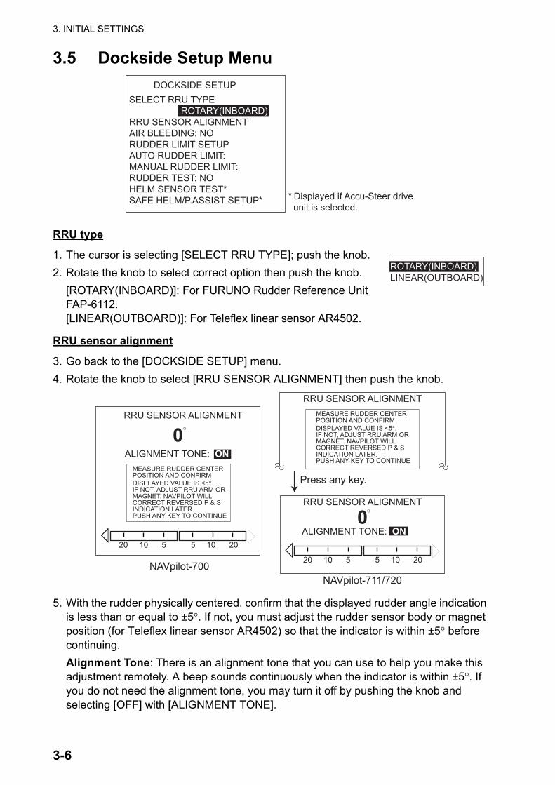
3.5 Dockside Setup Menu
RRU type
1. The cursor is selecting [SELECT RRU TYPE]; push the knob.2. Rotate the knob to select correct option then push the knob.
[ROTARY(INBOARD)]: For FURUNO Rudder Reference Unit FAP-6112.[LINEAR(OUTBOARD)]: For Teleflex linear sensor AR4502.
RRU sensor alignment
3. Go back to the [DOCKSIDE SETUP] menu.4. Rotate the knob to select [RRU SENSOR ALIGNMENT] then push the knob.
5. With the rudder physically centered, confirm that the displayed rudder angle indication is less than or equal to ±5°. If not, you must adjust the rudder sensor body or magnet position (for Teleflex linear sensor AR4502) so that the indicator is within ±5° before continuing.Alignment Tone: There is an alignment tone that you can use to help you make this adjustment remotely. A beep sounds continuously when the indicator is within ±5°. If you do not need the alignment tone, you may turn it off by pushing the knob and selecting [OFF] with [ALIGNMENT TONE].
DOCKSIDE SETUP
* Displayed if Accu-Steer drive unit is selected.
SELECT RRU TYPE ROTARY(INBOARD)RRU SENSOR ALIGNMENTAIR BLEEDING: NORUDDER LIMIT SETUPAUTO RUDDER LIMIT:MANUAL RUDDER LIMIT:RUDDER TEST: NOHELM SENSOR TEST*SAFE HELM/P.ASSIST SETUP*
ROTARY(INBOARD)LINEAR(OUTBOARD)
0
0
NAVpilot-700
MEASURE RUDDER CENTERPOSITION AND CONFIRMDISPLAYED VALUE IS <5°.IF NOT, ADJUST RRU ARM ORMAGNET. NAVPILOT WILLCORRECT REVERSED P & SINDICATION LATER.PUSH ANY KEY TO CONTINUE
RRU SENSOR ALIGNMENT
ALIGNMENT TONE: ON
Press any key.
RRU SENSOR ALIGNMENTMEASURE RUDDER CENTERPOSITION AND CONFIRMDISPLAYED VALUE IS <5°.IF NOT, ADJUST RRU ARM ORMAGNET. NAVPILOT WILL CORRECT REVERSED P & SINDICATION LATER.PUSH ANY KEY TO CONTINUE
NAVpilot-711/720
RRU SENSOR ALIGNMENT
ALIGNMENT TONE: ON
�
�
20 10 5 5 10 20
�
�
20 10 5 5 10 20
3. INITIAL SETTINGS
3-7
Air bleeding
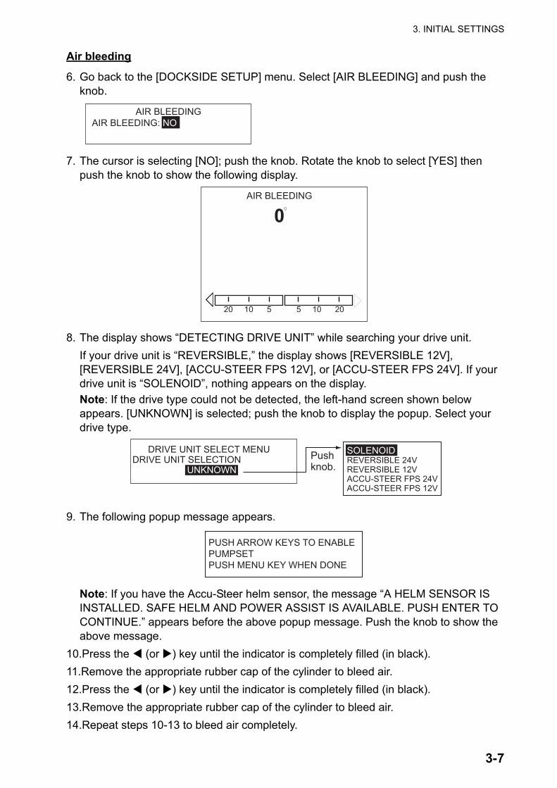
6. Go back to the [DOCKSIDE SETUP] menu. Select [AIR BLEEDING] and push the knob.
7. The cursor is selecting [NO]; push the knob. Rotate the knob to select [YES] then push the knob to show the following display.
8. The display shows “DETECTING DRIVE UNIT” while searching your drive unit.If your drive unit is “REVERSIBLE,” the display shows [REVERSIBLE 12V], [REVERSIBLE 24V], [ACCU-STEER FPS 12V], or [ACCU-STEER FPS 24V]. If your drive unit is “SOLENOID”, nothing appears on the display.Note: If the drive type could not be detected, the left-hand screen shown below appears. [UNKNOWN] is selected; push the knob to display the popup. Select your drive type.
9. The following popup message appears.
Note: If you have the Accu-Steer helm sensor, the message “A HELM SENSOR IS INSTALLED. SAFE HELM AND POWER ASSIST IS AVAILABLE. PUSH ENTER TO CONTINUE.” appears before the above popup message. Push the knob to show the above message.
10.Press the (or ) key until the indicator is completely filled (in black).11.Remove the appropriate rubber cap of the cylinder to bleed air.12.Press the (or ) key until the indicator is completely filled (in black).13.Remove the appropriate rubber cap of the cylinder to bleed air.14.Repeat steps 10-13 to bleed air completely.
AIR BLEEDING AIR BLEEDING: NO
AIR BLEEDING
0
�
�
20 10 5 5 10 20
DRIVE UNIT SELECT MENUDRIVE UNIT SELECTION UNKNOWN
SOLENOIDREVERSIBLE 24VREVERSIBLE 12VACCU-STEER FPS 24VACCU-STEER FPS 12V
Pushknob.
PUSH ARROW KEYS TO ENABLEPUMPSETPUSH MENU KEY WHEN DONE
3. INITIAL SETTINGS
3-8
Rudder limit setup
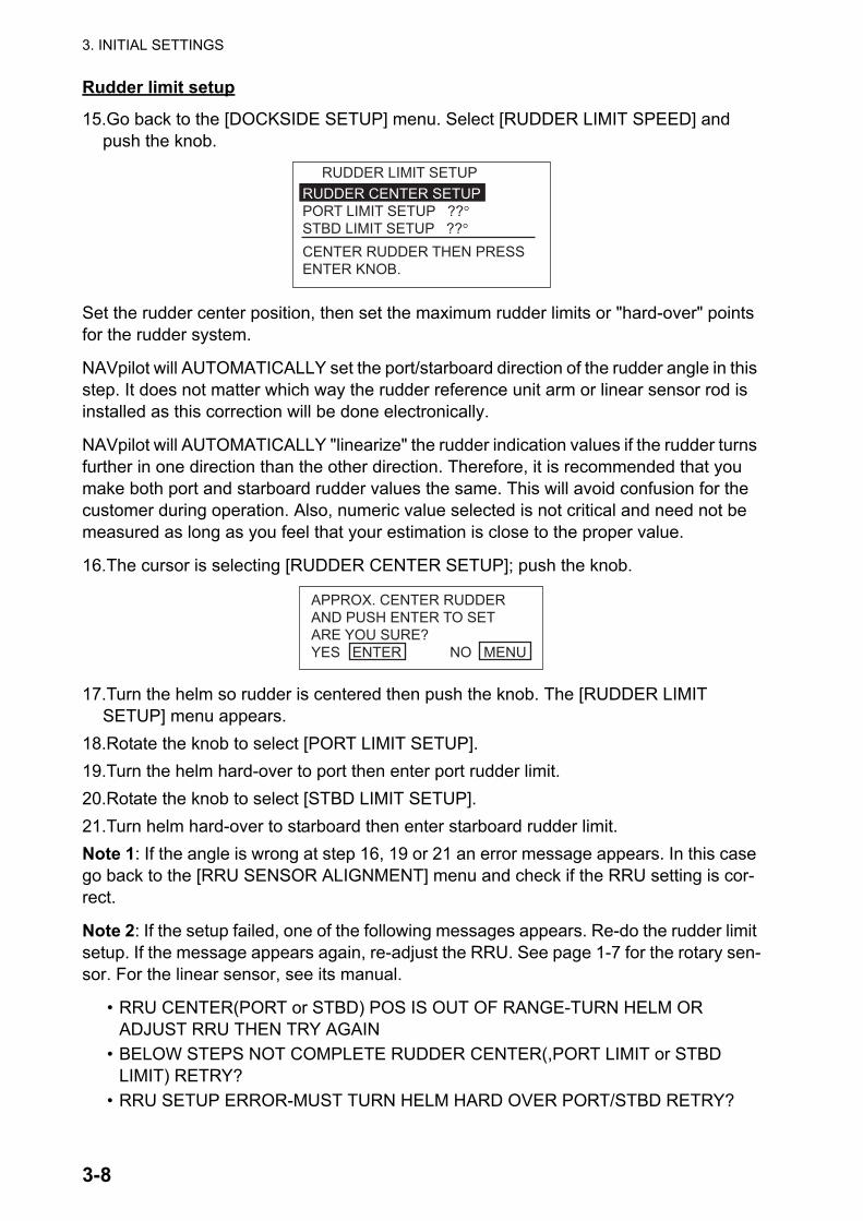
15.Go back to the [DOCKSIDE SETUP] menu. Select [RUDDER LIMIT SPEED] and push the knob.
Set the rudder center position, then set the maximum rudder limits or "hard-over" points for the rudder system.
NAVpilot will AUTOMATICALLY set the port/starboard direction of the rudder angle in this step. It does not matter which way the rudder reference unit arm or linear sensor rod is installed as this correction will be done electronically.
NAVpilot will AUTOMATICALLY "linearize" the rudder indication values if the rudder turns further in one direction than the other direction. Therefore, it is recommended that you make both port and starboard rudder values the same. This will avoid confusion for the customer during operation. Also, numeric value selected is not critical and need not be measured as long as you feel that your estimation is close to the proper value.
16.The cursor is selecting [RUDDER CENTER SETUP]; push the knob.
17.Turn the helm so rudder is centered then push the knob. The [RUDDER LIMIT SETUP] menu appears.
18.Rotate the knob to select [PORT LIMIT SETUP].19.Turn the helm hard-over to port then enter port rudder limit.20.Rotate the knob to select [STBD LIMIT SETUP].21.Turn helm hard-over to starboard then enter starboard rudder limit.Note 1: If the angle is wrong at step 16, 19 or 21 an error message appears. In this case go back to the [RRU SENSOR ALIGNMENT] menu and check if the RRU setting is cor-rect.
Note 2: If the setup failed, one of the following messages appears. Re-do the rudder limit setup. If the message appears again, re-adjust the RRU. See page 1-7 for the rotary sen-sor. For the linear sensor, see its manual.
• RRU CENTER(PORT or STBD) POS IS OUT OF RANGE-TURN HELM OR ADJUST RRU THEN TRY AGAIN
• BELOW STEPS NOT COMPLETE RUDDER CENTER(,PORT LIMIT or STBD LIMIT) RETRY?
• RRU SETUP ERROR-MUST TURN HELM HARD OVER PORT/STBD RETRY?
RUDDER CENTER SETUPPORT LIMIT SETUP ??°STBD LIMIT SETUP ??°
RUDDER LIMIT SETUP
CENTER RUDDER THEN PRESSENTER KNOB.
APPROX. CENTER RUDDERAND PUSH ENTER TO SETARE YOU SURE?YES ENTER NO MENU
3. INITIAL SETTINGS
3-9
Auto rudder limit
Auto rudder limit determines the maximum rudder movement in degrees from the mid po-sition in the Auto, Nav, Turn, Fish Hunter, Dodge and Wind modes. The value set here should not be greater than the limit set for Rudder Limit.
22.Go back to the [DOCKSIDE SETUP] menu, select [AUTO RUDDER LIMIT:] then push the knob. The current value is circumscribed with a double rectangle.
23.Rotate the knob to set the rudder limit desired then push the knob. (Setting range: 10° to max. rudder limit)
Manual rudder limit
In the Remote (FU and NU), FU Dodge or NFU Dodge modes, usually a wide range of rudder angles are used, and therefore a larger number should be entered. However, the setting must not exceed the rudder limit angle which is inherent on your boat.
Do not set the limit higher than the rudder limit. It is recommended to set the manual rud-der limit equal to or greater than the auto rudder limit. If the manual rudder limit is set lower than the auto one, the rudder may be returned to center position too quickly when the ves-sel is doing automatic turning by operation from the remote controller or DODGE key.
24.Go back to the [DOCKSIDE SETUP] menu and select [MANUAL RUDDER LIMIT:] then push the knob. The current value is circumscribed with a double rectangle.
25.Rotate the knob to set the rudder limit desired then push the knob. (Setting range: 10° to max. rudder limit)
Rudder test
For power steering vessels with an engine driven power steering pump, the engines must be running and slightly above idle before this test is done. BEFORE doing this test, check that [RUDDER DEADBAND] in the [SEA TRIAL] menu is set to [AUTO].
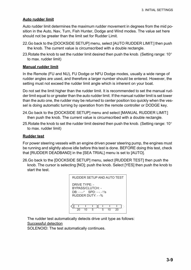
26.Go back to the [DOCKSIDE SETUP] menu, select [RUDDER TEST] then push the knob. The cursor is selecting [NO]; push the knob. Select [YES] then push the knob to start the test.
The rudder test automatically detects drive unit type as follows:Successful detectionSOLENOID: The test automatically continues.
RUDDER SETUP AND AUTO TEST
DRIVE TYPE: -BYPASS/CLUTCH: -DB: - -.-° SPD: - -. -°/sRUDDER DUTY: - -%
�
�
20 10 5 5 10 20

3. INITIAL SETTINGS
3-10
REVERSIBLE: The following menu appears. Select correct drive unit type with the Course control knob and push the knob. Then, the test continues.
Note: IN PORT1 and INPORT2 are disabled when ACCU-STEER is selected.Failed detection“RUDDER TEST FAILED” appears. The rudder test is discontinued.When the rudder test is finished, the message "RUDDER TEST COMPLETED." appears.The results are shown on the screen as follows:[DRIVE TYPE]: [REVERSIBLE12V](or 24V), [ACCU-STEER 12V](or 24V), or SOLE-NOID[BYPASS/CLUTCH]: [NOT PRESENT] or [PRESENT][DB]: Rudder deadband. If rudder DB is higher than 1.3°, the boat cannot be con-trolled correctly. In this case, open the [SEA TRIAL] menu, set [RUDDER DEAD-BAND] to [MANUAL] then adjust rudder deadband so that no hunching occurs.[SPD]: Rudder speed. If out of the recommended value for the NAVpilot, a warning message appears.[RUDDER DUTY]: PWM (Pulse Width Modulation) duty cycle for control of pump out-put. • For solenoid systems, the rudder duty indication is 100% always.• For reversing motor system, this value should be in a range from 50% to 100% for
optimum performance. If the value is lower than 50%, the pump capacity is over-sized for the steering cylinder volume. While the system may work well, there is a chance that the pump will fail to start (stalled pump) when there is a heavy load on the rudder system in heavy seas or large turns because the average voltage applied to the pump is too low. If the rudder speed is lower than 3 degrees/s and the rudder duty is higher than 90%, the pump capacity is undersized for the steering cylinder volume. While the system may also work well, the NAVpilot control unit may not be able to increase the average voltage to the pump adequately to improve the NAVpi-lot performance in heavy or following seas.
• If the boat type is “sailboat”, the rudder duty indication is 100% always. (Even if the speed exceeds 5°/s, no damage will result.)
27.Press the [MENU] key to return to the [DOCKSIDE SETUP] menu.28.Set the deadband of the rudder, automatically or manually. The setting is normally
performed automatically during the RUDDER TEST. Manually setting the parameter is normally not recommended and may in fact be only useful on older vessels with chain driven or old worn rudder system. If it is necessary to set it manually, do the following:1) Select [RUDDER DEADBAND] on the [SEA TRIAL] menu then push the knob.2) Select [MANUAL] then push the knob.3) Rotate the knob to select the value shown then push the knob.4) Rotate the knob to set the value shown then push the knob.
DRIVE UNIT SELECT MENUDRIVE UNIT SELECTIONREVERSIBLE 24VREVERSIBLE 12VACCU-STEER FPS 24VACCU-STEER FPS 12V
3. INITIAL SETTINGS
3-11
Note 1: If rudder DB is higher than 1.3°, the boat cannot be controlled correctly. Check for air in the steering system and if the rudder speed is greater than 10°/s.
Note 2: If you set the deadband manually, do not set the value too low. Hunching can re-sult.
Note 3: if the rudder test could not be completed successfully one of the following mes-sages appears. Do the test again after resolving the problem.
• RUDDER TEST FAILED. • RUDDER SPEED IS TOO FAST TOO CONTROL THE VESSEL. THE VESSEL MAY
NOT BE CONTROLLED PROPERLY.• RUDDER SPEED IS TOO SLOW TO CONTROL THE VESSEL. THE VESSEL MAY
NOT BE CONTROLLED PROPERLY.• DEADBAND IS TOO BIG TO CONTROL THE VESSEL. THE VESSEL MAY NOT BE
CONTROLLED PROPERLY. PLEASE SEE INST MANUAL FOR MANUAL DB SET-TING.
• RUDDER ANGLE ERROR CHECK DRIVE CIRCUIT• RUDDER DRIVE ERROR
Helm sensor test (for Accu-Steer FPS 12V (or 24V) drive)
The helm sensor test checks the connection between the processor unit and theAccu-Steer FPS 12V (or 24V) drive. If your drive unit is different, go to section 3.6.
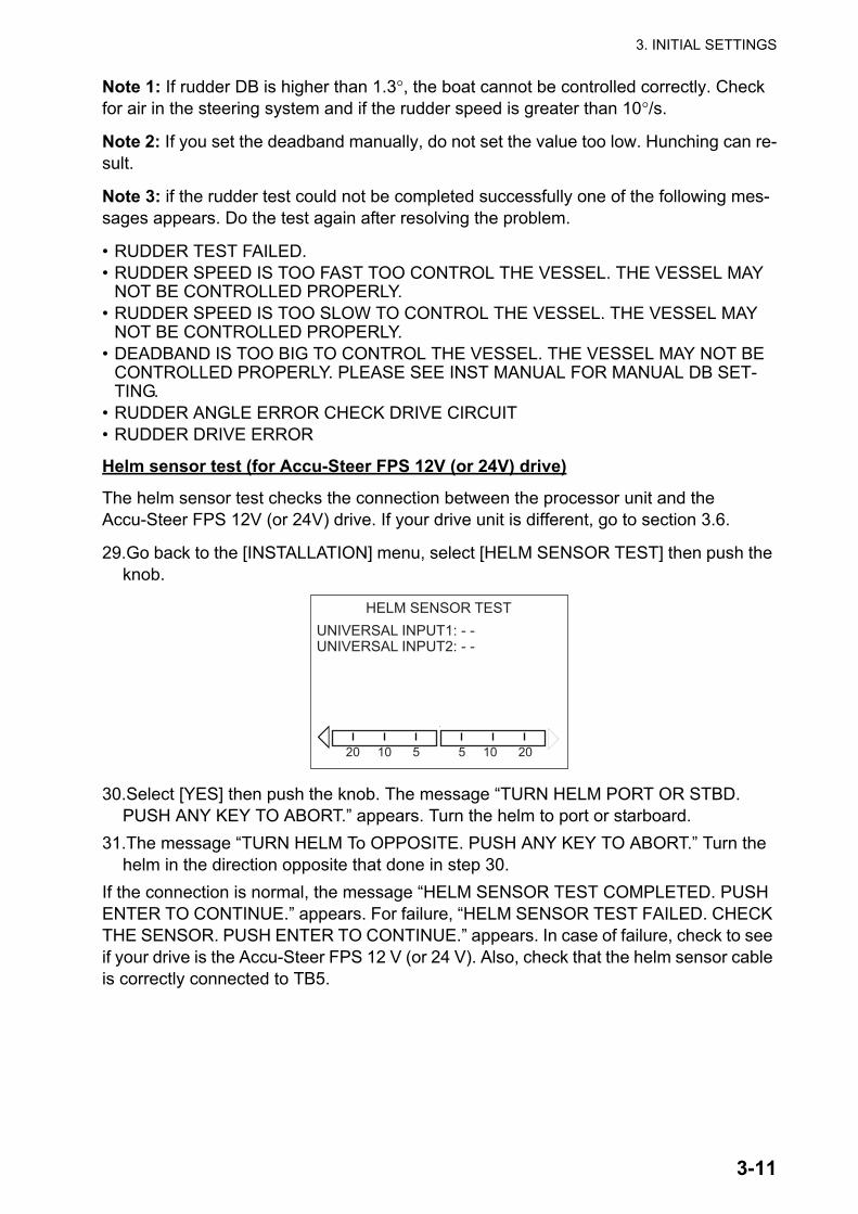
29.Go back to the [INSTALLATION] menu, select [HELM SENSOR TEST] then push the knob.
30.Select [YES] then push the knob. The message “TURN HELM PORT OR STBD. PUSH ANY KEY TO ABORT.” appears. Turn the helm to port or starboard.
31.The message “TURN HELM To OPPOSITE. PUSH ANY KEY TO ABORT.” Turn the helm in the direction opposite that done in step 30.
If the connection is normal, the message “HELM SENSOR TEST COMPLETED. PUSH ENTER TO CONTINUE.” appears. For failure, “HELM SENSOR TEST FAILED. CHECK THE SENSOR. PUSH ENTER TO CONTINUE.” appears. In case of failure, check to see if your drive is the Accu-Steer FPS 12 V (or 24 V). Also, check that the helm sensor cable is correctly connected to TB5.
HELM SENSOR TEST
�
�
20 10 5 5 10 20
UNIVERSAL INPUT1: - -UNIVERSAL INPUT2: - -
3. INITIAL SETTINGS
3-12
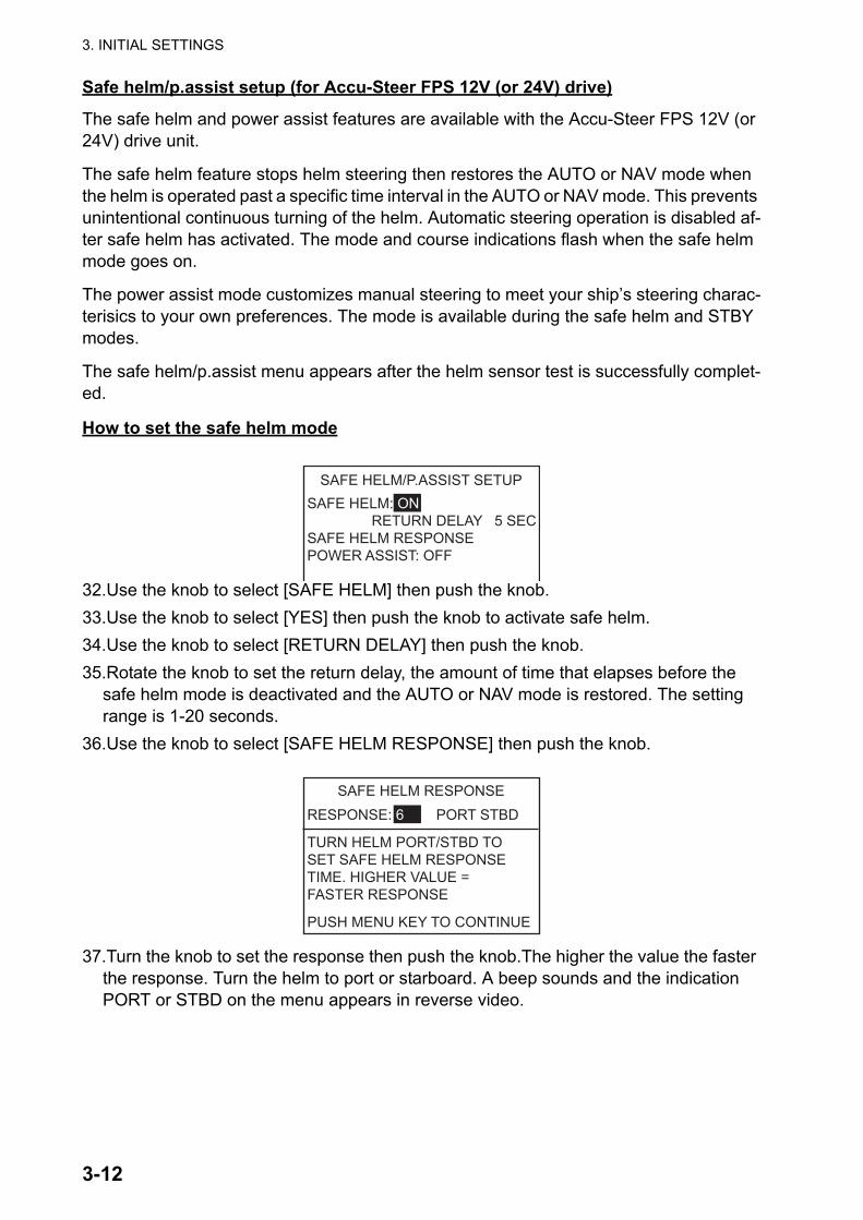
Safe helm/p.assist setup (for Accu-Steer FPS 12V (or 24V) drive)
The safe helm and power assist features are available with the Accu-Steer FPS 12V (or 24V) drive unit.
The safe helm feature stops helm steering then restores the AUTO or NAV mode when the helm is operated past a specific time interval in the AUTO or NAV mode. This prevents unintentional continuous turning of the helm. Automatic steering operation is disabled af-ter safe helm has activated. The mode and course indications flash when the safe helm mode goes on.
The power assist mode customizes manual steering to meet your ship’s steering charac-terisics to your own preferences. The mode is available during the safe helm and STBY modes.
The safe helm/p.assist menu appears after the helm sensor test is successfully complet-ed.
How to set the safe helm mode
32.Use the knob to select [SAFE HELM] then push the knob.33.Use the knob to select [YES] then push the knob to activate safe helm.34.Use the knob to select [RETURN DELAY] then push the knob.35.Rotate the knob to set the return delay, the amount of time that elapses before the
safe helm mode is deactivated and the AUTO or NAV mode is restored. The setting range is 1-20 seconds.
36.Use the knob to select [SAFE HELM RESPONSE] then push the knob.
37.Turn the knob to set the response then push the knob.The higher the value the faster the response. Turn the helm to port or starboard. A beep sounds and the indication PORT or STBD on the menu appears in reverse video.
SAFE HELM/P.ASSIST SETUPSAFE HELM: ON RETURN DELAY 5 SECSAFE HELM RESPONSEPOWER ASSIST: OFF
SAFE HELM RESPONSERESPONSE: 6 PORT STBD TURN HELM PORT/STBD TOSET SAFE HELM RESPONSETIME. HIGHER VALUE =FASTER RESPONSE
PUSH MENU KEY TO CONTINUE
3. INITIAL SETTINGS
3-13
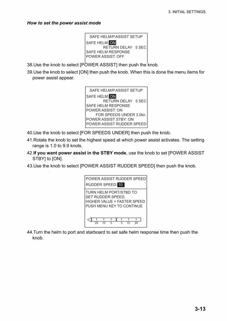
How to set the power assist mode
38.Use the knob to select [POWER ASSIST] then push the knob.39.Use the knob to select [ON] then push the knob. When this is done the menu items for
power assist appear.
40.Use the knob to select [FOR SPEEDS UNDER] then push the knob.41.Rotate the knob to set the highest speed at which power assist activates. The setting
range is 1.0 to 9.9 knots.42.If you want power assist in the STBY mode, use the knob to set [POWER ASSIST
STBY] to [ON].43.Use the knob to select [POWER ASSIST RUDDER SPEED] then push the knob.
1.
44.Turn the helm to port and starboard to set safe helm response time then push the knob.
SAFE HELM/P.ASSIST SETUPSAFE HELM: ON RETURN DELAY 5 SECSAFE HELM RESPONSEPOWER ASSIST: OFF
SAFE HELM/P.ASSIST SETUPSAFE HELM: ON RETURN DELAY 5 SECSAFE HELM RESPONSEPOWER ASSIST: ON FOR SPEEDS UNDER 3.0knPOWER ASSIST STBY: ONPOWER ASSIST RUDDER SPEED
POWER ASSIST RUDDER SPEEDRUDDER SPEED: 10 TURN HELM PORT/STBD TOSET RUDDER SPEED.HIGHER VALUE = FASTER SPEEDPUSH MENU KEY TO CONTINUE
�
�
20 10 5 5 10 20
3. INITIAL SETTINGS
3-14
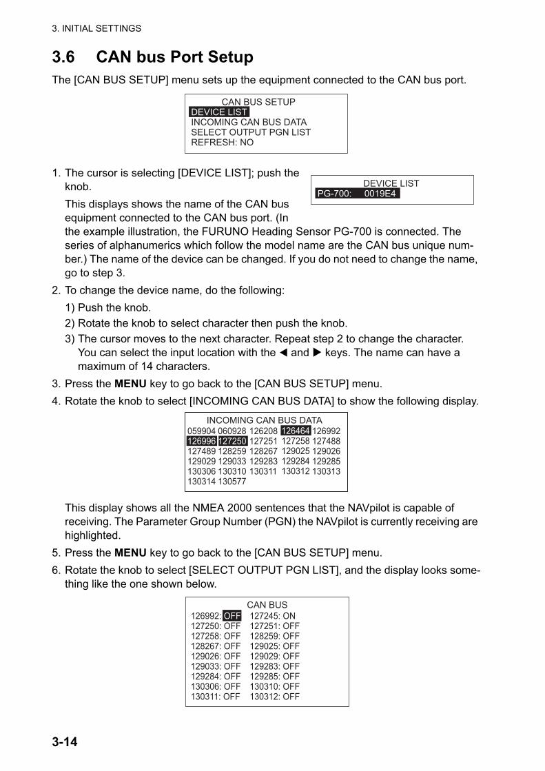
3.6 CAN bus Port SetupThe [CAN BUS SETUP] menu sets up the equipment connected to the CAN bus port.
1. The cursor is selecting [DEVICE LIST]; push the knob.This displays shows the name of the CAN bus equipment connected to the CAN bus port. (In the example illustration, the FURUNO Heading Sensor PG-700 is connected. The series of alphanumerics which follow the model name are the CAN bus unique num-ber.) The name of the device can be changed. If you do not need to change the name, go to step 3.
2. To change the device name, do the following:1) Push the knob.2) Rotate the knob to select character then push the knob.3) The cursor moves to the next character. Repeat step 2 to change the character.
You can select the input location with the and keys. The name can have a maximum of 14 characters.
3. Press the MENU key to go back to the [CAN BUS SETUP] menu.4. Rotate the knob to select [INCOMING CAN BUS DATA] to show the following display.
This display shows all the NMEA 2000 sentences that the NAVpilot is capable of receiving. The Parameter Group Number (PGN) the NAVpilot is currently receiving are highlighted.
5. Press the MENU key to go back to the [CAN BUS SETUP] menu.6. Rotate the knob to select [SELECT OUTPUT PGN LIST], and the display looks some-
thing like the one shown below.
CAN BUS SETUP DEVICE LISTINCOMING CAN BUS DATASELECT OUTPUT PGN LISTREFRESH: NO
DEVICE LISTPG-700: 0019E4
INCOMING CAN BUS DATA126992127488129026129285130313
126464127258129025129284130312
126208127251128267129283130311
059904126996127489129029130306130314
060928127250128259129033130310130577
CAN BUS127245: ON127251: OFF128259: OFF129025: OFF129029: OFF129283: OFF129285: OFF130310: OFF130312: OFF
126992: OFF127250: OFF127258: OFF128267: OFF129026: OFF129033: OFF129284: OFF130306: OFF130311: OFF

3. INITIAL SETTINGS
3-15
This display shows all the NMEA 2000 sentences that can be output to the NAVpilot. The sentences selected for output show “ON”. To turn a sentence ON or OFF, go to step 7. (Corresponding equipment must be connected to turn a sentence ON.) If you do not need to change the settings, go to step 8.
7. To turn an NMEA 2000 sentence on or off, do the following:1) Rotate the knob to select a sentence then push the knob.
2) Rotate the knob to select [ON] or [OFF] then push the knob.8. Press the MENU key to return to the [CAN BUS SETUP] menu.9. Rotate the knob to select [REFRESH] then push the knob.10.Wait five seconds to allow the system to refresh the device list.
3.7 NMEA0183 Port Setup
1. The cursor is selecting [PORT1]; push the knob.
2. The cursor is selecting [NAMING: PORT1]. This menu item lets you change the name of the port. For example, equipment type, model number, etc. The name can have a maximum of 14 alphanumeric characters. If you don’t need to change the name, go to step 3.1) Push the knob.2) Rotate the knob to select character then push the knob.3) The cursor moves to the next character. Repeat step 2 to change the character.
You can select the input location with the and keys. 3. Rotate the knob to select [OUTPUT FMT] then push the knob.4. Rotate the knob to select the output format of the equipment then
push the knob.5. Rotate the knob to select [BAUDRATE] then push the knob.6. Rotate the knob to select the baud rate of the equipment then push the
knob.
ONOFF
NMEA0183 SETUP PORT1PORT2
NMEA0183 PORT1 NAMING: PORT1OUTPUT FMT: NMEA0183 V3.0BAUDRATE: 4800BPSSELECT OUTPUT SENTENCEINCOMING NMEA0183 DATA
NMEA0183 V1.5NMEA0183 V2.0NMEA0183 V3.0
4800BPS38400BPS
3. INITIAL SETTINGS
3-16
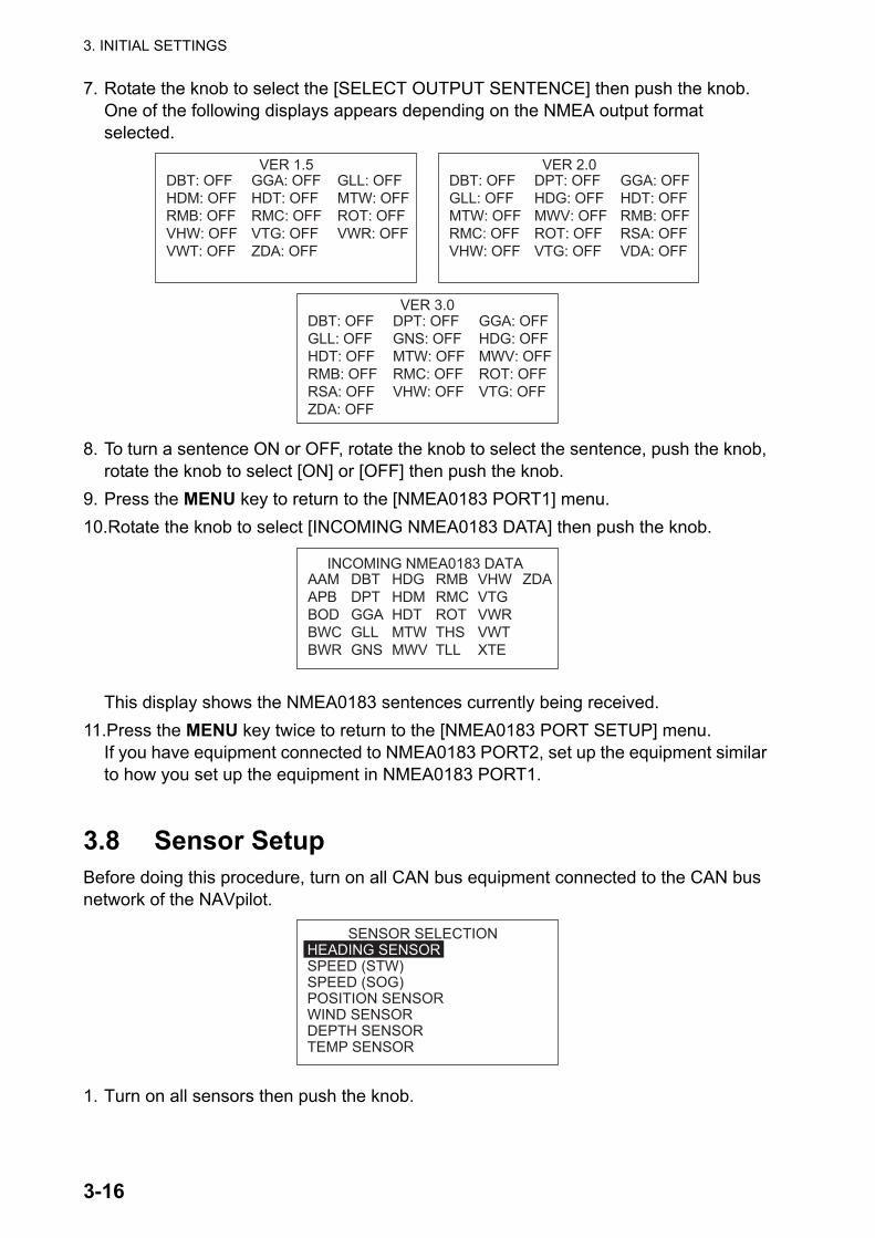
7. Rotate the knob to select the [SELECT OUTPUT SENTENCE] then push the knob. One of the following displays appears depending on the NMEA output format selected.
8. To turn a sentence ON or OFF, rotate the knob to select the sentence, push the knob, rotate the knob to select [ON] or [OFF] then push the knob.
9. Press the MENU key to return to the [NMEA0183 PORT1] menu.10.Rotate the knob to select [INCOMING NMEA0183 DATA] then push the knob.
This display shows the NMEA0183 sentences currently being received.11.Press the MENU key twice to return to the [NMEA0183 PORT SETUP] menu.
If you have equipment connected to NMEA0183 PORT2, set up the equipment similar to how you set up the equipment in NMEA0183 PORT1.
3.8 Sensor SetupBefore doing this procedure, turn on all CAN bus equipment connected to the CAN bus network of the NAVpilot.
1. Turn on all sensors then push the knob.
VER 3.0DBT: OFFGLL: OFFHDT: OFFRMB: OFFRSA: OFFZDA: OFF
DPT: OFFGNS: OFFMTW: OFFRMC: OFFVHW: OFF
GGA: OFFHDG: OFFMWV: OFFROT: OFFVTG: OFF
DBT: OFFHDM: OFFRMB: OFFVHW: OFFVWT: OFF
GLL: OFFMTW: OFFROT: OFFVWR: OFF
GGA: OFFHDT: OFFRMC: OFFVTG: OFFZDA: OFF
VER 1.5DBT: OFFGLL: OFFMTW: OFFRMC: OFFVHW: OFF
GGA: OFFHDT: OFFRMB: OFFRSA: OFFVDA: OFF
DPT: OFFHDG: OFFMWV: OFFROT: OFFVTG: OFF
VER 2.0
AAMAPBBODBWCBWR
HDGHDMHDTMTWMWV
DBTDPTGGAGLLGNS
INCOMING NMEA0183 DATARMBRMCROTTHSTLL
VHWVTGVWRVWTXTE
ZDA
SENSOR SELECTION HEADING SENSORSPEED (STW)SPEED (SOG)POSITION SENSORWIND SENSORDEPTH SENSORTEMP SENSOR

3. INITIAL SETTINGS
3-17
2. The cursor is selecting [HEADING SENSOR]; push the knob.
When [AUTO DETECT] is selected to [YES], all the heading sensors connected to the NAVpilot are shown. In case of multiple heading sensors, the sensors are ordered by FURUNO CAN bus heading sensor, other CAN bus heading sensor, NMEA 0183 heading sensor. If desired you can change the order; select number, push the knob, rotate the knob to select a sensor then push the knob. [AUTO DETECT] automatically re-orders sensors in the above-mentioned order. Select [YES] at [AUTO DETECT] to re-order.
3. Set up speed, position, wind, depth and temp sensors similarly.
3.9 Universal Port Setup
The [UNIVERSAL PORT] menu sets up the GENERAL IN and GENERAL OUT ports.GENERAL IN: A switch box is connected to this port to control the NAVpilot from a remote location.GENERAL OUT: A buzzer sounds or a lamp lights at a remote location when the specified function is done on the NAVpilot.
If you have equipment connected to only the GENERAL OUT port, go to step 5.
1. The cursor is selecting the setting for [IN PORT1]; push the knob.
2. Rotate the knob to select the command or function for [IN PORT1]. This is the com-mand or function assigned to the switch box connected to this port.[DISABLE]: The port is disabled.[AP ENABLE]: Select ON to get full control of the boat with the NAVpilot. In the OFF setting only the STBY mode is available.[GO STBY]: The switch, when operated, puts the NAVpilot in the STBY mode.
HEADING SENSORAUTO DETECT : NO1ST: PG-700 : 0019E42ND: - - - - - - - - - - - - - - 3RD: - - - - - - - - - - - - - -
UNIVERSAL PORT IN PORT1: DISABLEIN PORT2: DISABLEOUT PORT1: DISABLEOUT PORT2: DISABLE
DISABLEAP ENABLEGO STBYGO AUTOPORT ARROW KEYSTBD ARROW KEYFUNCTION KEY*
* This feature is not available when boat type is selected as sailboat.
3. INITIAL SETTINGS
3-18
[GO AUTO]: The switch, when operated, puts the NAVpilot in the AUTO mode.[PORT ARROW KEY]: The switch, when operated, controls the key on the NAVpi-lot.[STBD ARROW KEY]: The switch, when operated, controls the key on the NAVpi-lot.[FUNCTION KEY]: Assign function of equipment connected to NAVpilot.
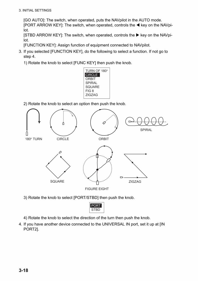
3. If you selected [FUNCTION KEY], do the following to select a function. If not go to step 4.1) Rotate the knob to select [FUNC KEY] then push the knob.
2) Rotate the knob to select an option then push the knob.
3) Rotate the knob to select [PORT/STBD] then push the knob.
4) Rotate the knob to select the direction of the turn then push the knob.4. If you have another device connected to the UNIVERSAL IN port, set it up at [IN
PORT2].
TURN OF 180°CIRCLEORBITSPIRALSQUAREFIG 8ZIGZAG
SQUARE
FIGURE EIGHT
ZIGZAG
SPIRAL
ORBITCIRCLE180° TURN
PORTSTBD

3. INITIAL SETTINGS
3-19
5. Rotate the knob to select [OUT PORT1] then push the knob.
6. Rotate the knob to select the action that triggers an external buzzer or lamp then push the knob.
7. If you have another device connected to the UNIVERSAL OUT port, set it up at [OUT PORT2].
3.10 Sea Trial
With a magnetic heading sensor (PG-500/700 etc.), magnetic variation information is nec-essary to display true heading data. In almost all cases, a GPS will be connected to the NAVpilot and the GPS will send this variation information to the NAVpilot automatically. Therefore, select "AUTO". In special cases where a manual variation is required, you may input these values manually. Note that this selection is only effective when the heading indication for the NAVpilot is selected to "TRUE".
When true heading display is selected in the [DISPLAY SETUP] menu, the NAVpilot will display true heading information even though the NAVpilot may be connected to a mag-netic heading sensor. This is very valuable when connecting a FURUNO radar FAR-21X7 series to the NAVpilot because these radars cannot be set for a magnetic heading input and the “Waypoint Lollipop" will only align properly when true heading is used.
If you have selected the FURUNO PG-500/700 as a heading sensor, do the procedure below to calibrate the compass and get automatic distortion compensation. Otherwise, go to step 4.
• The procedure is not applicable to other heading sensors.
EXT BUZZER*STBY MODEAUTO MODENAV MODEAUTO/NAV MODEAP CONTROLPORT ARROW KEYSTBD ARROW KEYDISABLE
* The [BUZZER] setting on the [ALARM] menu is automatically selected to [INTERNAL+EXTERNAL]. Applicable to both OUT PORT1 and OUT PORT2.
the NAVpilot goes into the STBY mode.the NAVpilot goes into the AUTO mode.the NAVpilot goes into the NAV mode.the NAVpilot switches between the AUTO and NAV modes and vice versa.the rudder is moved. the PORT arrow key (�) on the NAVpilot is operatedthe STBD arrow key (�) on the NAVpilot is operated.Function disabled.
A lamp lights or an external buzzer sounds when;
SEA TRIAL MAG. VAR.: AUTO --.-°COMPASS SETUPSET CENTER RUD. POS.RUDDER DEADBAND*: AUTO
COG - - -° HDG: T178°
* Set to AUTO to do rudder test. Set to MANUAL to adjust rudder deadband. See page 3-10.
3. INITIAL SETTINGS
3-20
• It is not necessary to perform any adjustments locally at the PG-500/700. NAVpilot has full control of these heading sensors.
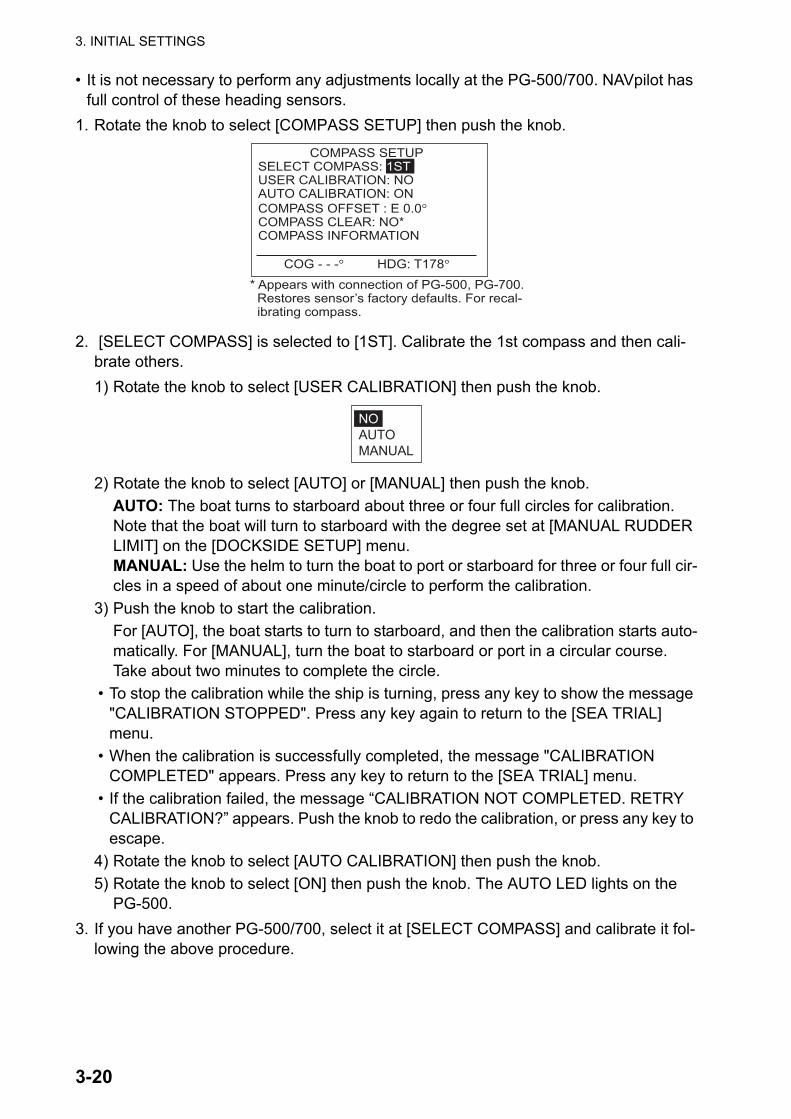
1. Rotate the knob to select [COMPASS SETUP] then push the knob.
2. [SELECT COMPASS] is selected to [1ST]. Calibrate the 1st compass and then cali-brate others.1) Rotate the knob to select [USER CALIBRATION] then push the knob.
2) Rotate the knob to select [AUTO] or [MANUAL] then push the knob.AUTO: The boat turns to starboard about three or four full circles for calibration. Note that the boat will turn to starboard with the degree set at [MANUAL RUDDER LIMIT] on the [DOCKSIDE SETUP] menu.MANUAL: Use the helm to turn the boat to port or starboard for three or four full cir-cles in a speed of about one minute/circle to perform the calibration.
3) Push the knob to start the calibration.For [AUTO], the boat starts to turn to starboard, and then the calibration starts auto-matically. For [MANUAL], turn the boat to starboard or port in a circular course. Take about two minutes to complete the circle.
• To stop the calibration while the ship is turning, press any key to show the message "CALIBRATION STOPPED". Press any key again to return to the [SEA TRIAL] menu.
• When the calibration is successfully completed, the message "CALIBRATION COMPLETED" appears. Press any key to return to the [SEA TRIAL] menu.
• If the calibration failed, the message “CALIBRATION NOT COMPLETED. RETRY CALIBRATION?” appears. Push the knob to redo the calibration, or press any key to escape.
4) Rotate the knob to select [AUTO CALIBRATION] then push the knob.5) Rotate the knob to select [ON] then push the knob. The AUTO LED lights on the
PG-500.3. If you have another PG-500/700, select it at [SELECT COMPASS] and calibrate it fol-
lowing the above procedure.
COMPASS SETUPSELECT COMPASS: 1STUSER CALIBRATION: NOAUTO CALIBRATION: ONCOMPASS OFFSET : E 0.0°COMPASS CLEAR: NO*COMPASS INFORMATION
COG - - -° HDG: T178°
* Appears with connection of PG-500, PG-700. Restores sensor’s factory defaults. For recal- ibrating compass.
NOAUTOMANUAL
3. INITIAL SETTINGS
3-21
4. If the heading data shown on the Control Unit differs from the indication of the ship's compass, apply an offset at [COMPASS OFFSET]. This offset is applied to the head-ing sensor data. For example, if the Control Unit display shows 125° though the ship's compass reading is 120°, for example, enter "5".1) Rotate the knob to select [COMPASS OFFSET] then push the knob.2) Rotate the knob to set a value (setting range: E0.0°-E180.0°, W0.1°-W179.9°) then
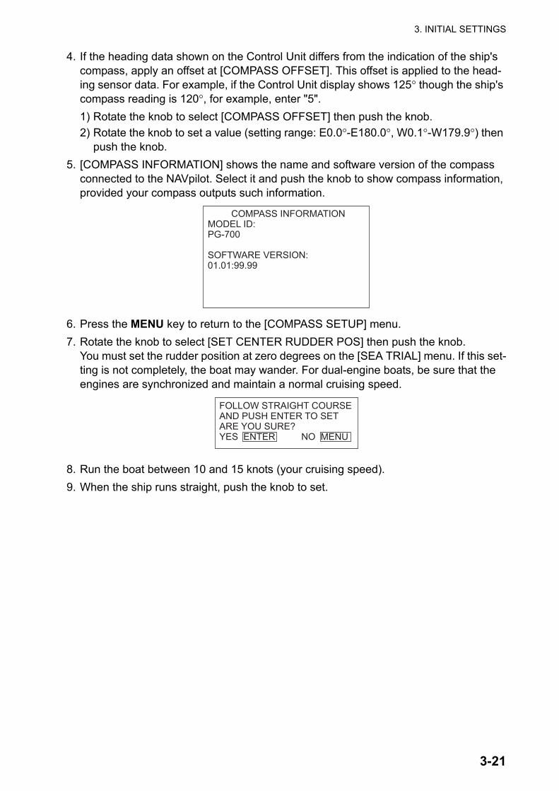
push the knob.5. [COMPASS INFORMATION] shows the name and software version of the compass
connected to the NAVpilot. Select it and push the knob to show compass information, provided your compass outputs such information.
6. Press the MENU key to return to the [COMPASS SETUP] menu.7. Rotate the knob to select [SET CENTER RUDDER POS] then push the knob.
You must set the rudder position at zero degrees on the [SEA TRIAL] menu. If this set-ting is not completely, the boat may wander. For dual-engine boats, be sure that the engines are synchronized and maintain a normal cruising speed.
8. Run the boat between 10 and 15 knots (your cruising speed).9. When the ship runs straight, push the knob to set.
COMPASS INFORMATIONMODEL ID:PG-700
SOFTWARE VERSION:01.01:99.99
FOLLOW STRAIGHT COURSEAND PUSH ENTER TO SETARE YOU SURE?YES ENTER NO MENU
3. INITIAL SETTINGS
3-22
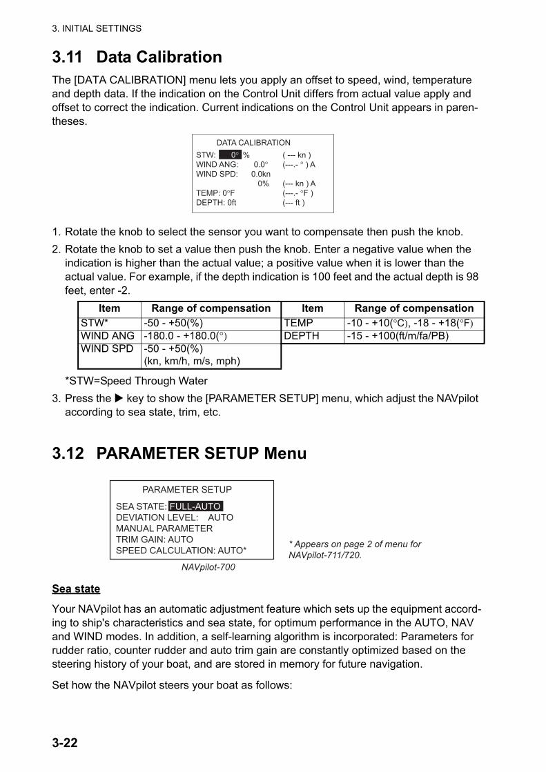
3.11 Data CalibrationThe [DATA CALIBRATION] menu lets you apply an offset to speed, wind, temperature and depth data. If the indication on the Control Unit differs from actual value apply and offset to correct the indication. Current indications on the Control Unit appears in paren-theses.
1. Rotate the knob to select the sensor you want to compensate then push the knob.2. Rotate the knob to set a value then push the knob. Enter a negative value when the
indication is higher than the actual value; a positive value when it is lower than the actual value. For example, if the depth indication is 100 feet and the actual depth is 98 feet, enter -2.
*STW=Speed Through Water3. Press the key to show the [PARAMETER SETUP] menu, which adjust the NAVpilot
according to sea state, trim, etc.
3.12 PARAMETER SETUP Menu
Sea state
Your NAVpilot has an automatic adjustment feature which sets up the equipment accord-ing to ship's characteristics and sea state, for optimum performance in the AUTO, NAV and WIND modes. In addition, a self-learning algorithm is incorporated: Parameters for rudder ratio, counter rudder and auto trim gain are constantly optimized based on the steering history of your boat, and are stored in memory for future navigation.
Set how the NAVpilot steers your boat as follows:
Item Range of compensation Item Range of compensationSTW* -50 - +50(%) TEMP -10 - +10(°C), -18 - +18(°F)WIND ANG -180.0 - +180.0(°) DEPTH -15 - +100(ft/m/fa/PB)WIND SPD -50 - +50(%)
(kn, km/h, m/s, mph)
DATA CALIBRATION STW: 0° % ( --- kn )WIND ANG: 0.0° (---.- ° ) AWIND SPD: 0.0kn 0% (--- kn ) ATEMP: 0°F (---.- °F )DEPTH: 0ft (--- ft )
PARAMETER SETUP
SEA STATE: FULL-AUTODEVIATION LEVEL: AUTOMANUAL PARAMETERTRIM GAIN: AUTOSPEED CALCULATION: AUTO*
NAVpilot-700
* Appears on page 2 of menu for NAVpilot-711/720.
3. INITIAL SETTINGS
3-23
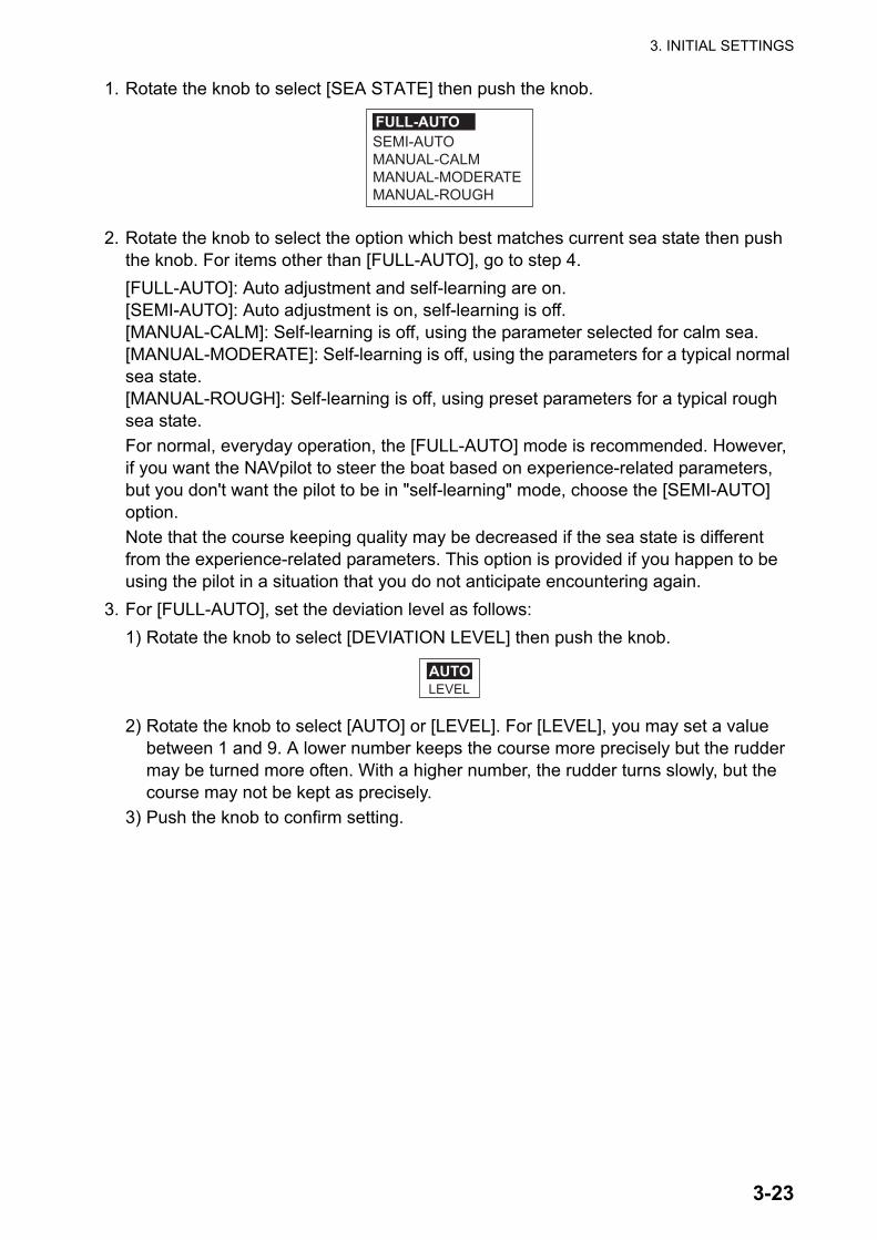
1. Rotate the knob to select [SEA STATE] then push the knob.
2. Rotate the knob to select the option which best matches current sea state then push the knob. For items other than [FULL-AUTO], go to step 4.[FULL-AUTO]: Auto adjustment and self-learning are on.[SEMI-AUTO]: Auto adjustment is on, self-learning is off.[MANUAL-CALM]: Self-learning is off, using the parameter selected for calm sea.[MANUAL-MODERATE]: Self-learning is off, using the parameters for a typical normal sea state.[MANUAL-ROUGH]: Self-learning is off, using preset parameters for a typical rough sea state.For normal, everyday operation, the [FULL-AUTO] mode is recommended. However, if you want the NAVpilot to steer the boat based on experience-related parameters, but you don't want the pilot to be in "self-learning" mode, choose the [SEMI-AUTO] option.Note that the course keeping quality may be decreased if the sea state is different from the experience-related parameters. This option is provided if you happen to be using the pilot in a situation that you do not anticipate encountering again.
3. For [FULL-AUTO], set the deviation level as follows:1) Rotate the knob to select [DEVIATION LEVEL] then push the knob.
2) Rotate the knob to select [AUTO] or [LEVEL]. For [LEVEL], you may set a value between 1 and 9. A lower number keeps the course more precisely but the rudder may be turned more often. With a higher number, the rudder turns slowly, but the course may not be kept as precisely.
3) Push the knob to confirm setting.
SEMI-AUTOMANUAL-CALMMANUAL-MODERATEMANUAL-ROUGH
FULL-AUTO
LEVELAUTO
3. INITIAL SETTINGS
3-24
How to manually set NAVpilot steering parameters
When [MANUAL-CALM], [MANUAL-MODERATE] or [MANUAL-ROUGH] is selected as the sea state, set [MANUAL PARAMETERS] as below.
You can set three parameters for the MANUAL function: Weather, Rudder gain and Counter rudder.
1. Rotate the knob to select [MANUAL PARAMETERS] from the [PARAMETER SETUP] menu then push the knob. The display now looks like the one shown below.
2. Rotate the knob to select the setting of [WEATHER-CALM] then press the knob.3. Rotate the knob to set value (0° to 10° for weather).4. Push the knob.5. Set [WEATHER-MODERATE], [WEATHER-ROUGH] and [RUDDER GAIN] and
[COUNT RUDDER] similarly (Setting range: 1-20 for rudder gain, 0-20 for counter rud-der).
6. Press the MENU key to finish.Guidelines for how to set SEA STATE
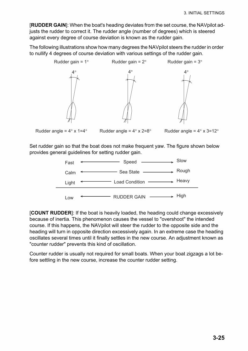
[WEATHER]: When the sea is rough, the boat's heading fluctuates to port and starboard. If the rudder is driven very often to maintain the set course, the helm mechanism may wear out. To prevent this, the weather adjustment makes the NAVpilot insensitive to minute course deviations. You may choose a degree between 0° to 10°. Until the course deviation exceeds the selected setting, steering to correct the heading will not be initiated.
The illustration at the top of the next page shows boat's track lines with weather setting 3° and 7°. When 7° is set, for example, the rudder is not driv-en until the course deviation exceeds 7°. Increas-ing the setting reduces activation of the steering gear, however the boat tends to zigzag. When the sea is calm, set a smaller value.
[CALM] [MODERATE] [ROUGH]
[WEATHER] 1° 2° 3°
[RUDDER GAIN] 3 5 10
[COUNT RUDDER] 1 2 4
7°
3°
Weather = 3° Weather = 7°
3. INITIAL SETTINGS
3-25
[RUDDER GAIN]: When the boat's heading deviates from the set course, the NAVpilot ad-justs the rudder to correct it. The rudder angle (number of degrees) which is steered against every degree of course deviation is known as the rudder gain.
The following illustrations show how many degrees the NAVpilot steers the rudder in order to nullify 4 degrees of course deviation with various settings of the rudder gain.
Set rudder gain so that the boat does not make frequent yaw. The figure shown below provides general guidelines for setting rudder gain.
[COUNT RUDDER]: If the boat is heavily loaded, the heading could change excessively because of inertia. This phenomenon causes the vessel to "overshoot" the intended course. If this happens, the NAVpilot will steer the rudder to the opposite side and the heading will turn in opposite direction excessively again. In an extreme case the heading oscillates several times until it finally settles in the new course. An adjustment known as "counter rudder" prevents this kind of oscillation.
Counter rudder is usually not required for small boats. When your boat zigzags a lot be-fore settling in the new course, increase the counter rudder setting.
Rudder gain = 1° Rudder gain = 2° Rudder gain = 3°
Rudder angle = 4° x 1=4° Rudder angle = 4° x 2=8° Rudder angle = 4° x 3=12°
4° 4° 4°
Speed
Sea State
Load Condition
RUDDER GAIN
Fast
Calm
Light
Low
Slow
Rough
Heavy
High
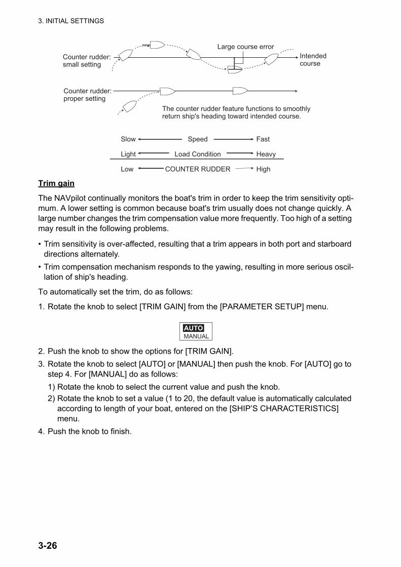
3. INITIAL SETTINGS
3-26
Trim gain
The NAVpilot continually monitors the boat's trim in order to keep the trim sensitivity opti-mum. A lower setting is common because boat's trim usually does not change quickly. A large number changes the trim compensation value more frequently. Too high of a setting may result in the following problems.
• Trim sensitivity is over-affected, resulting that a trim appears in both port and starboard directions alternately.
• Trim compensation mechanism responds to the yawing, resulting in more serious oscil-lation of ship's heading.
To automatically set the trim, do as follows:
1. Rotate the knob to select [TRIM GAIN] from the [PARAMETER SETUP] menu.
2. Push the knob to show the options for [TRIM GAIN].3. Rotate the knob to select [AUTO] or [MANUAL] then push the knob. For [AUTO] go to
step 4. For [MANUAL] do as follows:1) Rotate the knob to select the current value and push the knob.2) Rotate the knob to set a value (1 to 20, the default value is automatically calculated
according to length of your boat, entered on the [SHIP’S CHARACTERISTICS] menu.
4. Push the knob to finish.
Intendedcourse
Large course error
The counter rudder feature functions to smoothly return ship's heading toward intended course.
Counter rudder: small setting
Counter rudder: proper setting
Speed
Load Condition
COUNTER RUDDER
Slow
Light
Low
Fast
Heavy
High
MANUALAUTO
3. INITIAL SETTINGS
3-27
Speed calculation
Speed is normally entered automatically, from your navigator. If the navigator fails, man-ually enter speed.
1. Rotate the knob to select [SPEED CALCULATION] from the [PARAMETER SETUP] menu.
2. Push the knob to the options for [SPEED CALCULATION].
3. Rotate the knob to select [AUTO] or [MANUAL] then push the knob. For [AUTO] go to step 5. For [MANUAL], do as follows:1) Rotate the knob to select the current value and push the knob.2) Rotate the knob to set a value (0.1 - 99.0).
4. Push the knob to finish.
MANUALAUTO

3. INITIAL SETTINGS
3-28
3.13 AUTO OPTION Menu
.
After you have completed this menu, press the key to show the [NAV OPTION] menu. The [NAV OPTION] menu sets up the conditions for the NAV mode.
Item Description Settings[ADVANCEDAUTO]
The AUTO mode will maintain a set course, but your vessel's course may be shifted by the effects of tide and wind. To compensate for the effects of tide and wind, set [ADVANCED AUTO] to [ON]. Your NAVpilot must be connected to a GPSnavigator which outputs position data (Latitude and Longitude) in CAN bus or NMEA 0183 for-mat.
[OFF], [ON]
[NET TOW-ING AUTO]
When a boat is towing fishing gear its stern is "dragged" by the net. This causes the boat to stray from its intended course. To keep the boat on course, you need to adjust the trim manually, which can be bothersome. If you do not want to be bothered with trim adjustments, you can enable the automatic towing function to have the trim automatically adjusted. This feature is useful for trawlers and purse seiners.Not available for “boat type” “sailboat”.
[OFF], [ON]
[CSE AFTER REMOTE]
Select the course to follow after a remote control-ler is operated. See the figure below.
[PREVIOUS COURSE], [PRESENT COURSE]
AUTO OPTION
ADVANCED AUTO: ONNET TOWING AUTO: OFFCSE AFTER REMOTE: PRESENT COURSE
Not shown when SHIP’SCHARACTERISTICS is setfor “sailboat”.
Previous course
New course
Remote controller: OFF Remote
controller: ON
PRESENT COURSE mode
Remote controller: ON
Remote controller: OFF
Previous course
PREVIOUS COURSE mode
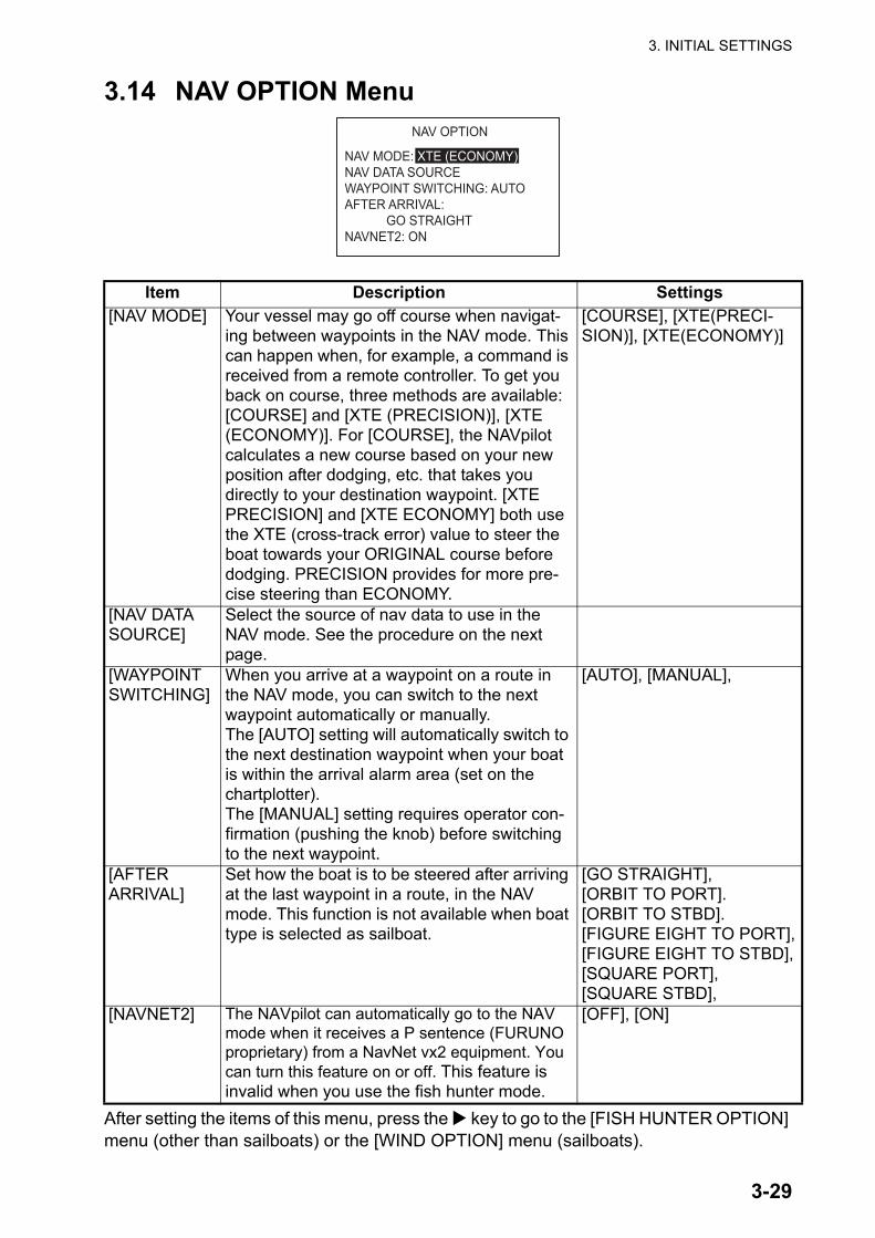
3. INITIAL SETTINGS
3-29
3.14 NAV OPTION Menu
After setting the items of this menu, press the key to go to the [FISH HUNTER OPTION] menu (other than sailboats) or the [WIND OPTION] menu (sailboats).
Item Description Settings[NAV MODE] Your vessel may go off course when navigat-
ing between waypoints in the NAV mode. This can happen when, for example, a command is received from a remote controller. To get you back on course, three methods are available: [COURSE] and [XTE (PRECISION)], [XTE (ECONOMY)]. For [COURSE], the NAVpilot calculates a new course based on your new position after dodging, etc. that takes you directly to your destination waypoint. [XTE PRECISION] and [XTE ECONOMY] both use the XTE (cross-track error) value to steer the boat towards your ORIGINAL course before dodging. PRECISION provides for more pre-cise steering than ECONOMY.
[COURSE], [XTE(PRECI-SION)], [XTE(ECONOMY)]
[NAV DATA SOURCE]
Select the source of nav data to use in the NAV mode. See the procedure on the next page.
[WAYPOINT SWITCHING]
When you arrive at a waypoint on a route in the NAV mode, you can switch to the next waypoint automatically or manually.The [AUTO] setting will automatically switch to the next destination waypoint when your boat is within the arrival alarm area (set on the chartplotter). The [MANUAL] setting requires operator con-firmation (pushing the knob) before switching to the next waypoint.
[AUTO], [MANUAL],
[AFTERARRIVAL]
Set how the boat is to be steered after arriving at the last waypoint in a route, in the NAV mode. This function is not available when boat type is selected as sailboat.
[GO STRAIGHT],[ORBIT TO PORT].[ORBIT TO STBD].[FIGURE EIGHT TO PORT],[FIGURE EIGHT TO STBD],[SQUARE PORT],[SQUARE STBD],
[NAVNET2] The NAVpilot can automatically go to the NAV mode when it receives a P sentence (FURUNO proprietary) from a NavNet vx2 equipment. You can turn this feature on or off. This feature is invalid when you use the fish hunter mode.
[OFF], [ON]
NAV OPTION
NAV MODE: XTE (ECONOMY)NAV DATA SOURCEWAYPOINT SWITCHING: AUTOAFTER ARRIVAL: GO STRAIGHTNAVNET2: ON
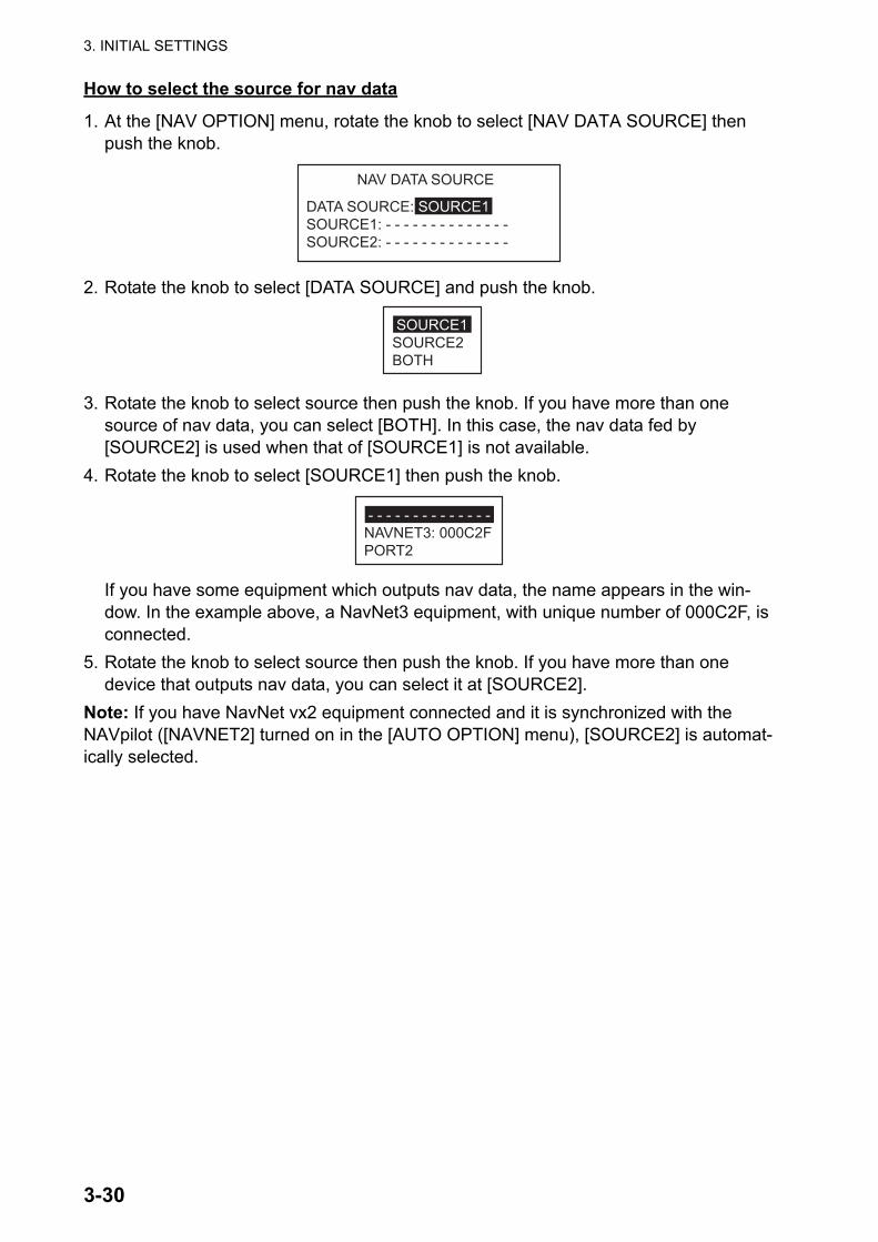
3. INITIAL SETTINGS
3-30
How to select the source for nav data
1. At the [NAV OPTION] menu, rotate the knob to select [NAV DATA SOURCE] then push the knob.
2. Rotate the knob to select [DATA SOURCE] and push the knob.
3. Rotate the knob to select source then push the knob. If you have more than one source of nav data, you can select [BOTH]. In this case, the nav data fed by [SOURCE2] is used when that of [SOURCE1] is not available.
4. Rotate the knob to select [SOURCE1] then push the knob.
If you have some equipment which outputs nav data, the name appears in the win-dow. In the example above, a NavNet3 equipment, with unique number of 000C2F, is connected.
5. Rotate the knob to select source then push the knob. If you have more than one device that outputs nav data, you can select it at [SOURCE2].
Note: If you have NavNet vx2 equipment connected and it is synchronized with the NAVpilot ([NAVNET2] turned on in the [AUTO OPTION] menu), [SOURCE2] is automat-ically selected.
NAV DATA SOURCE
DATA SOURCE: SOURCE1SOURCE1: - - - - - - - - - - - - - -SOURCE2: - - - - - - - - - - - - - -
SOURCE1SOURCE2BOTH
- - - - - - - - - - - - - -NAVNET3: 000C2FPORT2

3. INITIAL SETTINGS
3-31
3.15 FISH HUNTER OPTION Menu or WIND OPTION Menu
Depending on the setting for [SHIP’S CHARACTERISTICS], the [FISH HUNTER OP-TION] menu or the [WIND OPTION] menu follows the [NAV OPTION] menu.
3.15.1 FISH HUNTER OPTION menuThe [FISH HUNTER OPTION] menu lets you preset the parameters for the various turns, which you access with the TURN key (NAVpilot-700) or TURN/MENU key (NAVpilot-711/720).
CIRCLE
RATE OF TURN: 3 °/s
ORBIT
RADIUS: 0.05 nm
SPIRAL
SPEED: 0.5 kn RADIUS: 0.05nm
FIGURE 8
RADIUS: 0.05 nm
SQUARE TURN
SIDE LENGTH: 1.0 nm AZIMUTH: AUTO
ZIGZAG
TURN ANGLE: 90 ° TERMINATION: CONTINUOUSDISTANCE:NUMBER OF TURNS:WIDTH: 0.5nm
DISTANCECONTINUOUS
NUMBER OF TURNS
MANUALAUTO
FISH HUNTER OPTION
CIRCLEORBITSPIRALFIGURE 8SQUARE TURNZIGZAG
1 Setting range depends on units selected on the [UNIT SETUP] menu.
CIRCLE 1° - 5°/sORBITSPIRAL
Radius: 0.05 - 9.99nmFIGURE 8SQUARETURN
Side Length: 1.0 - 9.9nmAzimuth: 0 - 359°(Manual)
ZIGZAG Turn Angle: 30° - 150°Number of Turns: 1 - 20Distance: 1 - 99nmWidth: 0.1 - 9.9nm
Speed: 0.1 - 2.0kn
0.05 - 9.99nm
0.05 - 9.99nm
Set at menu item NUMBER OF TURNS.Set at menu item DISTANCE.
Item Setting range1
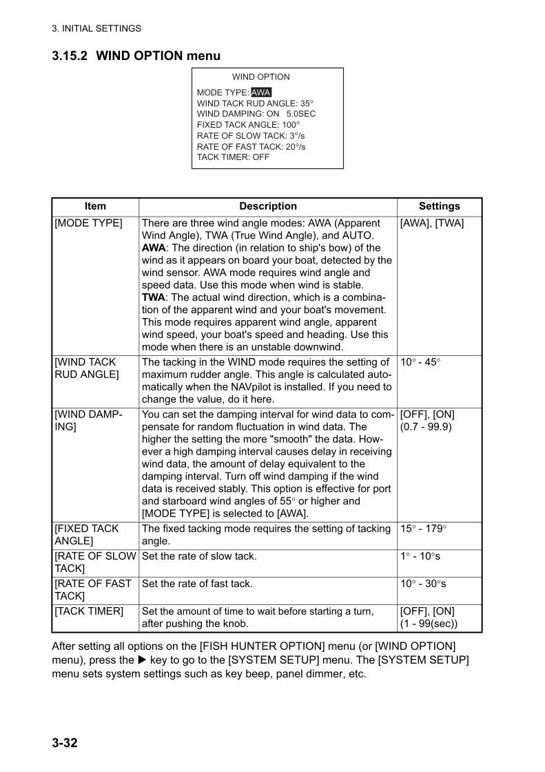
3. INITIAL SETTINGS
3-32
3.15.2 WIND OPTION menu
After setting all options on the [FISH HUNTER OPTION] menu (or [WIND OPTION] menu), press the key to go to the [SYSTEM SETUP] menu. The [SYSTEM SETUP] menu sets system settings such as key beep, panel dimmer, etc.
Item Description Settings[MODE TYPE] There are three wind angle modes: AWA (Apparent
Wind Angle), TWA (True Wind Angle), and AUTO.AWA: The direction (in relation to ship's bow) of the wind as it appears on board your boat, detected by the wind sensor. AWA mode requires wind angle and speed data. Use this mode when wind is stable.TWA: The actual wind direction, which is a combina-tion of the apparent wind and your boat's movement. This mode requires apparent wind angle, apparent wind speed, your boat's speed and heading. Use this mode when there is an unstable downwind.
[AWA], [TWA]
[WIND TACKRUD ANGLE]
The tacking in the WIND mode requires the setting of maximum rudder angle. This angle is calculated auto-matically when the NAVpilot is installed. If you need to change the value, do it here.
10° - 45°
[WIND DAMP-ING]
You can set the damping interval for wind data to com-pensate for random fluctuation in wind data. The higher the setting the more "smooth" the data. How-ever a high damping interval causes delay in receiving wind data, the amount of delay equivalent to the damping interval. Turn off wind damping if the wind data is received stably. This option is effective for port and starboard wind angles of 55° or higher and [MODE TYPE] is selected to [AWA].
[OFF], [ON](0.7 - 99.9)
[FIXED TACKANGLE]
The fixed tacking mode requires the setting of tacking angle.
15° - 179°
[RATE OF SLOWTACK]
Set the rate of slow tack. 1° - 10°s
[RATE OF FAST TACK]
Set the rate of fast tack. 10° - 30°s
[TACK TIMER] Set the amount of time to wait before starting a turn, after pushing the knob.
[OFF], [ON](1 - 99(sec))
WIND OPTION
MODE TYPE: AWAWIND TACK RUD ANGLE: 35°WIND DAMPING: ON 5.0SECFIXED TACK ANGLE: 100°RATE OF SLOW TACK: 3°/sRATE OF FAST TACK: 20°/sTACK TIMER: OFF

3. INITIAL SETTINGS
3-33
3.16 SYSTEM SETUP Menu
SAVE ENGINNER SETTING: Save the settings in the menus with the following excep-tions:
• DISPLAY SETUP (except DATA BOX FORMAT, TEMP GRAPH)• DOCKSIDE SETUP (except SELECT RRU TYPE, RRU SENSOR ALIGNMENT,
AIR BLEEDING, RUDDER LIMIT SETUP, RUDDER TEST, HELM SENSOR TEST)• CAN BUS SETUP (except INCOMING CAN BUS DATA, REFRESH)• NMEA 0183 SETUP PORT1, PORT2 (except REFRESH)• SENSOR SELECTION (except AUTO DETECT)• SEA TRIAL (except COMPASS, USER CALIBRATION, COMPASS CLEAR, COM-
PASS INFORMATION, SET CENTER RUDDR POS)• SYSTEM SETUP (KEY BEEP, BUZZER VOL, KEY LOCK, PANEL DIMMER,
RECEIVE SCREEN, ALL CLEAR, SAVE/LOAD USER SETTINGS, SAVE/LOAD ENGINEER SETTING, DIAGNOSTIC, DISPLAY DATA SELECT MENU, SYSTEM DATA)
• ALARM MENU (CLEAR TRIP LOG)LOAD ENGINEER SETTING: Load the settings saved with SAVE ENGINEER SETTING:
For other items, section 4.6 “SYSTEM SETUP menu” in the Operator’s Manual.
Page 1SYSTEM SETUP
KEY BEEP: OFFBUZZER VOL: LARGEARROW KEY: DODGEKEY LOCK: UNLOCKTURN ANGLE: 15PANEL DIMMER: 8PASSWORD: 0000 PASSWORD FUNCTION: OFFRECEIVE SCREEN: OFFSAVE USER SETTING: NOLOAD USER SETTING: NOSAVE DISPLAY SETTINGS: NOLOAD DISPLAY SETTINGS: NO
SYSTEM SETUPSAVE ENGINEER SETTING: NOLOAD ENGINEER SETTING: NOALARM LOGSIM/DEMO: OFFDIAGNOSTIC: OFFDISPLAY DATA SELECT MENUSYSTEM DATA
Page 2

3. INITIAL SETTINGS
3-34
3.17 RC (Remote Controller) SETUP Menu
Set the type of remote controller you have as follows
1. The setting for [REMOTE CONTROLLER 1] is selected; push the knob.2. Rotate the knob to select the type of remote controller connected.
[NFU]: Select for button- or lever-type remote controller. [FU]: Select for dial-type remote controller. [DODGE]: Select for dodge-type remote controller. [DISABLE]: Disable remote controller operation.
3. Set the type for remote controller 2, if connected.4. Press the key to show the [ALARM SETUP] menu. For how to set this menu, see
Chapter 3 in the Operator’s Manual.5. After reviewing the [ALARM SETUP menu], press the key to show the following
message.
6. Press the key to save all settings. To recheck your settings, press the key. This concludes the initial settings.
3.18 All ClearThe all clear feature restores all default settings. Open the [INSTALLATION] and [SYS-TEM SETUP] menus. Select [ALL CLEAR] and [YES] to restore all default settings.
RC SETUP
REMOTE CONTROLLER1: DISABLEREMOTE CONTROLLER2: DISABLE
NFUFUDODGEDISABLE
SETTINGS ARE REGISTEREDAS ENGINEER SETTINGSARE YOU SURE?
PREV � YES � NO MENU

AP-1
JIS CABLE GUIDE
D
T
M
TT
P Y
C Y S
-S
3. Sheath Type
4. Armor Type 5. Shielding Type 6. Core Sheath
Ethylene Propylene
2. Insulation Type 1. Core Type Double core power line
Triple core power line
1mm Multi core
0.75mm twisted pair communications (1Q = quad cable)
Corrosive resistantSteel
Vinyl
All cores in one sheath
Individually sheathed cores
DPYCYS - 1.5 EX:
The following reference table lists gives the measurements of JIS cables commonly used with Furuno products:
DPYC
TTYCS-4
MPYC-5
Type Area Diameter
Core Cable
Diameter
DPYC-1.5 1.5mm2 1.56mm 11.7mm
DPYC-2.5 2.5mm2 2.01mm
1 2 3 4 5 6
MPYC - 51 2 3 4
Designation type Core Area (mm ) Designation type # of cores
DPYCY-2.5
DPYCYS-1.5
DPYCYS-2.5
MPYC-7
MPYCY-12
MPYCY-19
TTYCS-1
TTYCS-1Q
TTYCS-4
TTYCYS-1
JIS cable names may have up to 6 alphabetical characters, followed by a dash and a numerical value (example: DPYC-2.5). For core types D and T, the numerical designation indicates the cross-sectional Area (mm2) of the core wire(s) in the cable. For core types M and TT, the numerical designation indicates the number of core wires in the cable.
TPYC
12.8mm
2.5mm2 2.01mm 14.8mm
1.5mm2 1.56mm 14.6mm
2.5mm2 2.01mm 15.5mm
1mm2 1.29mm 13.2mm
1mm2 1.29mm 19.0mm
22.0mm1mm2 1.29mm
0.75mm2 1.11mm 10.1mm
11.3mm
16.3mm
21.1mm
2
0.75mm 1.11mm2
0.75mm 1.11mm2
0.75mm 1.11mm2
Type Area Diameter
Core Cable
Diameter
MPYC-4
MPYC-2
TPYCY-1.5
TPYCY-2.5
TPYCY-4
TPYCYS-1.5
1mm2
1mm2
1.5mm2 1.56mm 14.5mm
2.5mm2 2.01mm 15.5mm
4mm2 2.55mm 16.9mm
1.5mm2 1.56mm 15.2mm
Cables listed in the manual are usually shown as Japanese Industrial Standard (JIS). Use the following guide to locate an
1.29mm
1.29mm 10.0mm
11.2mm
equivalent cable locally.
DPY-1.5
DPY-2.5
TPY-2.5
1.5mm2 1.56mm 10.4mm
2.5mm2 2.01mm 11.5mm
2.5mm2 2.01mm 12.2mm
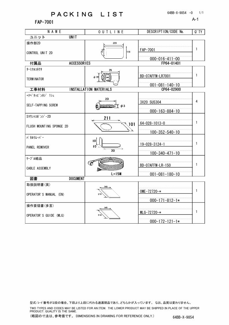
PACKING LIST 64BB-X-9854 -0
FAP-7001
N A M E O U T L I N E DESCRIPTION/CODE № Q'TY
1/1
ユニット UNIT
操作部2D
CONTROL UNIT 2DFAP-7001
000-016-411-00
1
付属品 ACCESSORIES FP64-01401
ターミナルコネクタ
TERMINATORBD-07AFFM-LR7001
001-081-140-10
1
工事材料 INSTALLATION MATERIALS CP64-02900
+ナベタッピンネジ 1シュ
SELF-TAPPING SCREW3X20 SUS304
000-163-884-10
4
Sマウントスポンジ-2D
FLUSH MOUNTING SPONGE 2D64-028-1013-0
100-352-540-10
1
パネルリムーバー
PANEL REMOVER19-028-3124-1
100-340-471-10
1
ケーブル組品
CABLE ASSEMBLYBD-07AFFM-LR-150
001-081-180-10
1
図書 DOCUMENT
取扱説明書(英)
OPERATOR'S MANUAL (EN)OME-72720-*
000-171-812-1*
1
操作要領書(多言)
OPERATOR'S GUIDE (MLG)MLG-72720-*
000-172-121-1*
1
(略図の寸法は、参考値です。 DIMENSIONS IN DRAWING FOR REFERENCE ONLY.) 64BB-X-9854
型式/コード番号が2段の場合、下段より上段に代わる過渡期品であり、どちらかが入っています。 なお、品質は変わりません。
TWO TYPES AND CODES MAY BE LISTED FOR AN ITEM. THE LOWER PRODUCT MAY BE SHIPPED IN PLACE OF THE UPPER PRODUCT. QUALITY IS THE SAME.
A-1
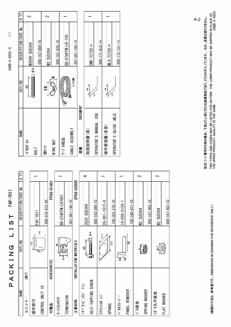
NAME
OUTLINE
Q'TY
DESCRIPTION/CODE №
PA
CK
ING
L
IST
64BB-X-9855-0
FAP-7011
1/1
NAME
OUTLINE
Q'TY
DESCRIPTION/CODE №
ユニ
ット
UNIT
操作部1D
CONTROL UNIT 1D
1FAP-7011
000-016-412-00
付属
品ACCESSORIES
FP64-01401
ターミナルコネクタ
TERMINATOR
1BD-07AFFM-LR7001
001-081-140-10
工事
材料
INSTALLATION MATERIALS
CP64-03000
+ナベタッピンネジ 1シュ
SELF-TAPPING SCREW
43X20 SUS304
000-163-884-10
Sマウントスポンジ
SPONGE
126-001-1012-0
100-352-270-10
パネルリムーハ
゙ー
PANEL REMOVER
119-028-3124-1
100-340-471-10
バネ座金
SPRING WASHER
2M3 SUS304
000-167-404-10
ミガキ丸
平座金
FLAT WASHER
2M3 SUS304
000-167-453-10
寸切ボルト
BOLT
2M3X40 SUS304
000-167-804-10
蝶ナット
WING NUT
2M3 SUS304
000-167-826-10
ケーブル組品
CABLE ASSEMBLY
1BD-07AFFM-LR-150
001-081-180-10
図書
DOCUMENT
取扱説
明書(英
)
OPERATOR'S MANUAL (EN)
1OME-72720-*
000-171-812-1*
操作要
領書(多
言)
OPERATOR'S GUIDE (MLG)
1MLG-72720-*
000-172-121-1*
(略
図の
寸法
は、
参考
値で
す。
DIM
EN
SIO
NS IN
DR
AW
ING
FO
R R
EFER
EN
CE O
NLY.)
64BB-X-9855
型式
/コー
ド番
号が
2段
の場
合、
下段
より
上段
に代
わる
過渡
期品
であ
り、
どち
らか
が入
って
いま
す。
な
お、
品質
は変
わり
ませ
ん。
TW
O T
YP
ES
AN
D C
OD
ES
MA
Y B
E L
ISTED
FO
R A
N ITEM
. T
HE L
OW
ER
PR
OD
UC
T M
AY B
E S
HIP
PED
IN
PLA
CE O
F
TH
E U
PP
ER
PR
OD
UC
T. Q
UA
LIT
Y IS
TH
E S
AM
E.
A-2
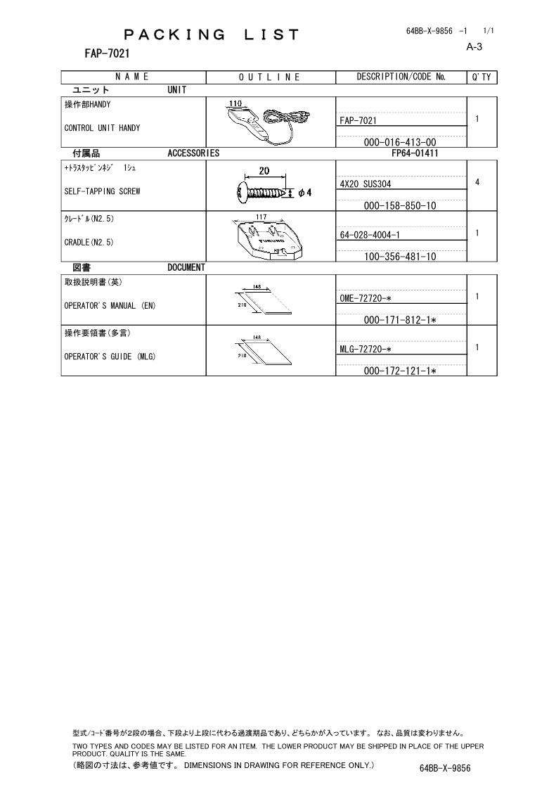
PACKING LIST 64BB-X-9856 -1
FAP-7021
N A M E O U T L I N E DESCRIPTION/CODE № Q'TY
1/1
ユニット UNIT
操作部HANDY
CONTROL UNIT HANDYFAP-7021
000-016-413-00
1
付属品 ACCESSORIES FP64-01411
+トラスタッピンネジ 1シュ
SELF-TAPPING SCREW4X20 SUS304
000-158-850-10
4
クレードル(N2.5)
CRADLE(N2.5)64-028-4004-1
100-356-481-10
1
図書 DOCUMENT
取扱説明書(英)
OPERATOR'S MANUAL (EN)OME-72720-*
000-171-812-1*
1
操作要領書(多言)
OPERATOR'S GUIDE (MLG)MLG-72720-*
000-172-121-1*
1
(略図の寸法は、参考値です。 DIMENSIONS IN DRAWING FOR REFERENCE ONLY.) 64BB-X-9856
型式/コード番号が2段の場合、下段より上段に代わる過渡期品であり、どちらかが入っています。 なお、品質は変わりません。
TWO TYPES AND CODES MAY BE LISTED FOR AN ITEM. THE LOWER PRODUCT MAY BE SHIPPED IN PLACE OF THE UPPER PRODUCT. QUALITY IS THE SAME.
A-3

PACKING LIST 64BB-X-9857 -1
FAP-7002/-11/-20
N A M E O U T L I N E DESCRIPTION/CODE № Q'TY
1/1
ユニット UNIT
制御部
PROCESSOR UNITFAP-7002/-11/-20
000-016-419-00
1
**
予備品 SPARE PARTS SP64-01501
ヒューズ
GLASS TUBE FUSEFGMB 125V 4A PBF
000-157-482-10
4
工事材料 INSTALLATION MATERIALS CP64-03101
+トラスタッピンネジ 1シュ
SELF-TAPPING SCREW4X20 SUS304
000-158-850-10
4
コンベックス
CABLE TIECV-80N
000-162-192-10
20
図書 DOCUMENT
装備要領書(英)
INSTALLATION MANUALIME-72720-*
000-171-813-1*
1
コ-ド番号末尾の[**]は、選択品の代表コードを表します。
CODE NUMBER ENDING WITH "**" INDICATES THE CODE NUMBER OF REPRESENTATIVE MATERIAL.
(略図の寸法は、参考値です。 DIMENSIONS IN DRAWING FOR REFERENCE ONLY.) 64BB-X-9857
型式/コード番号が2段の場合、下段より上段に代わる過渡期品であり、どちらかが入っています。 なお、品質は変わりません。
TWO TYPES AND CODES MAY BE LISTED FOR AN ITEM. THE LOWER PRODUCT MAY BE SHIPPED IN PLACE OF THE UPPER PRODUCT. QUALITY IS THE SAME.
A-4
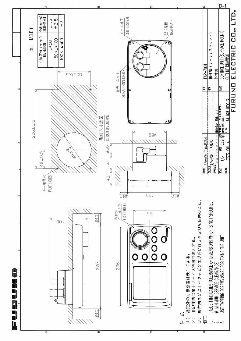
24/Nov/09 R.Esumi
D-1
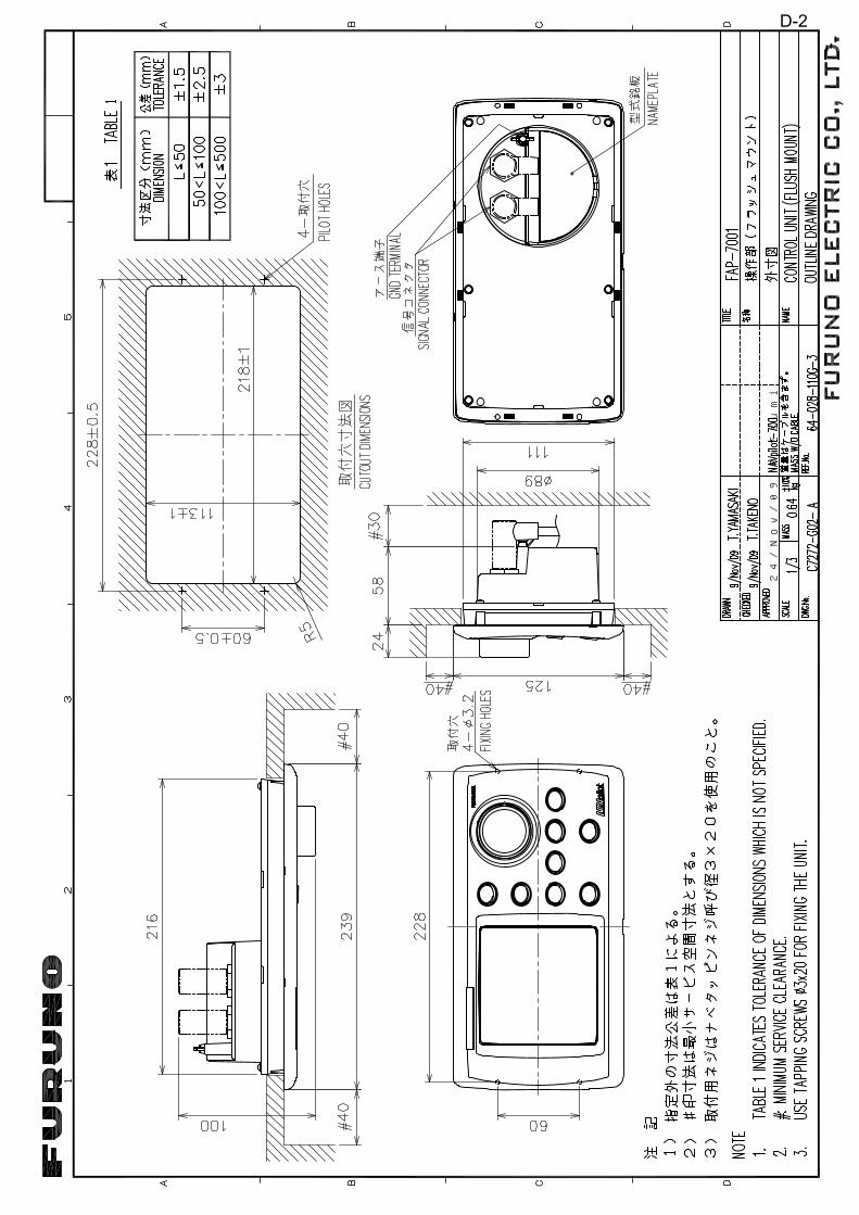
24/Nov/09 R.Esumi
D-2
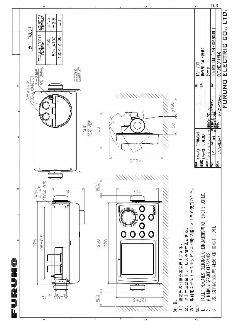
24/Nov/09 R.Esumi
D-3
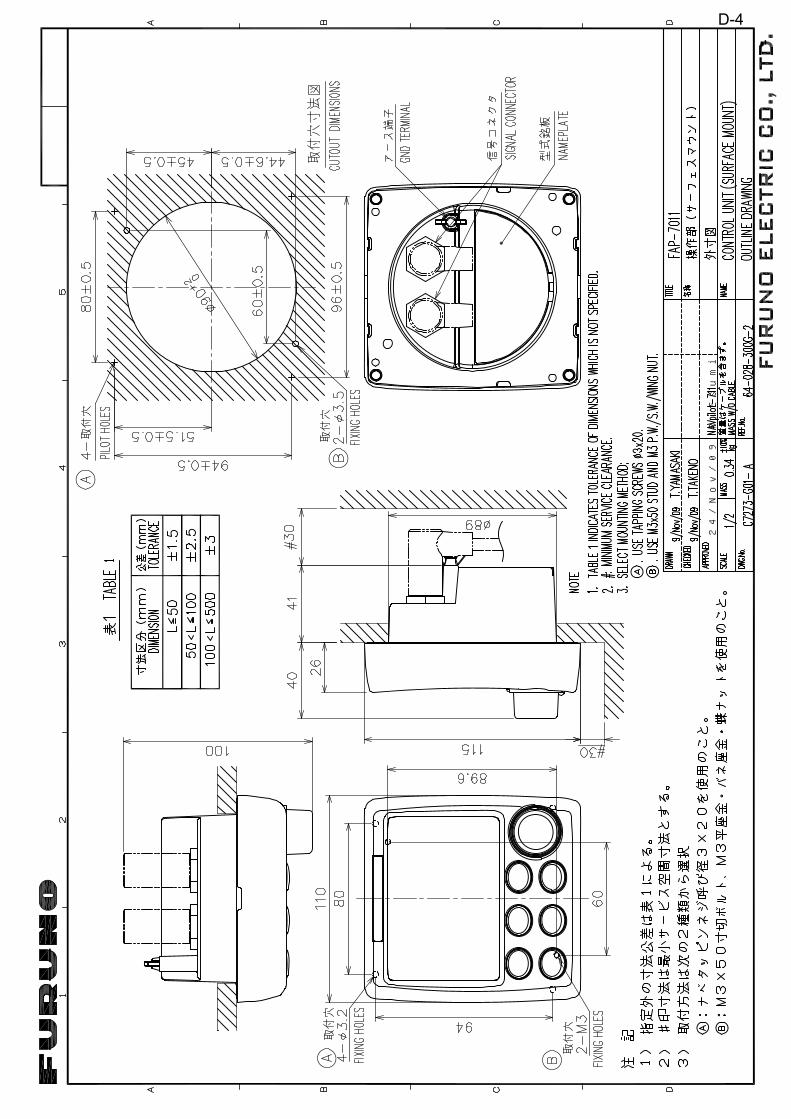
24/Nov/09 R.Esumi
D-4
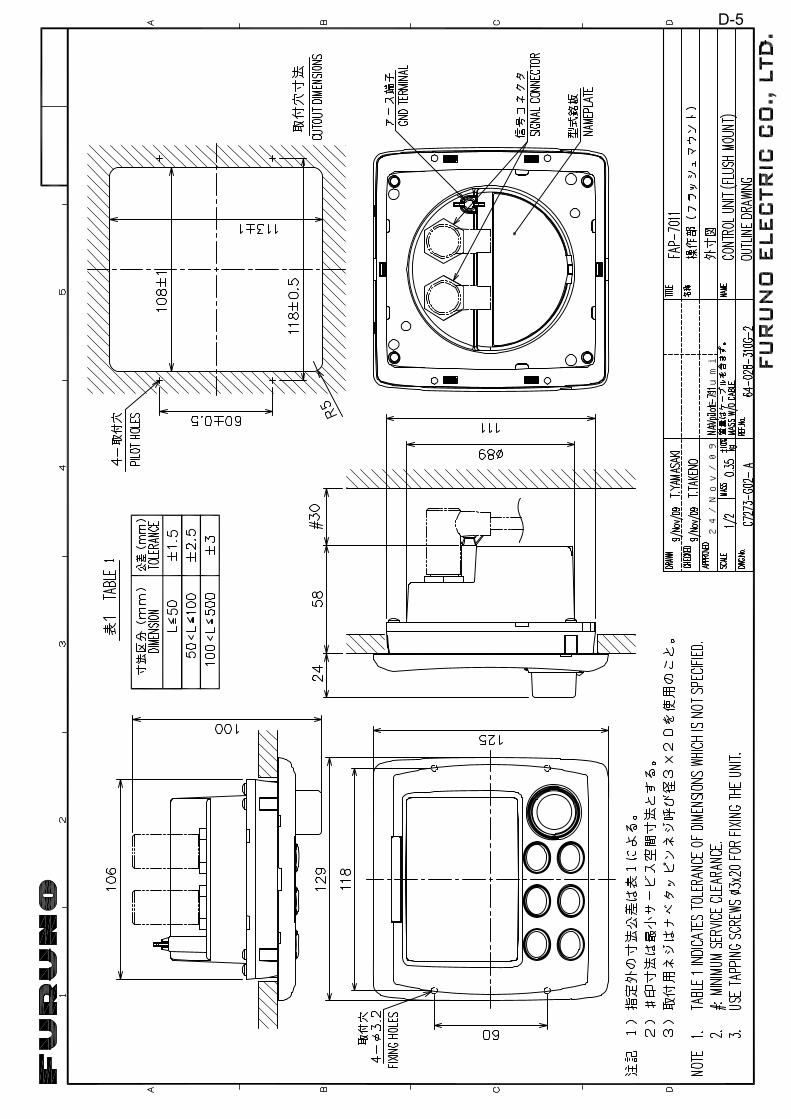
24/Nov/09 R.Esumi
D-5
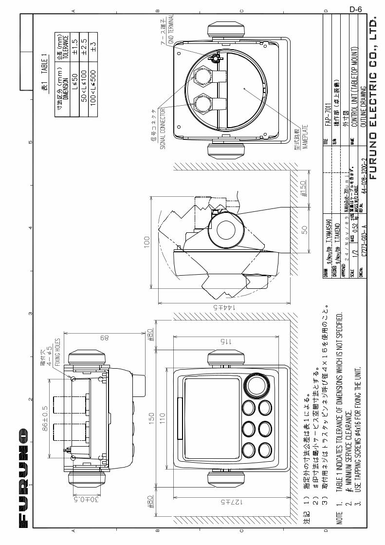
24/Nov/09 R.Esumi
D-6
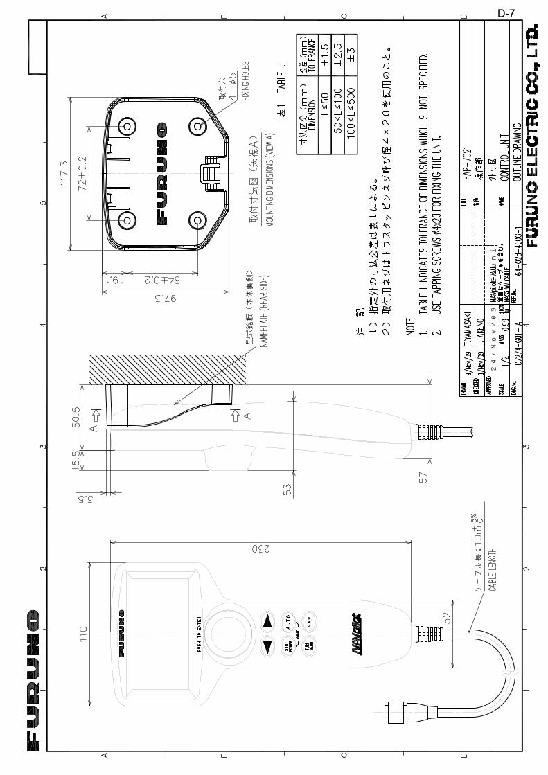
24/Nov/09 R.Esumi
D-7

24/Nov/09 R.Esumi
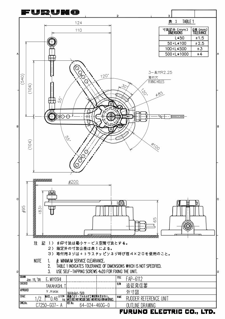
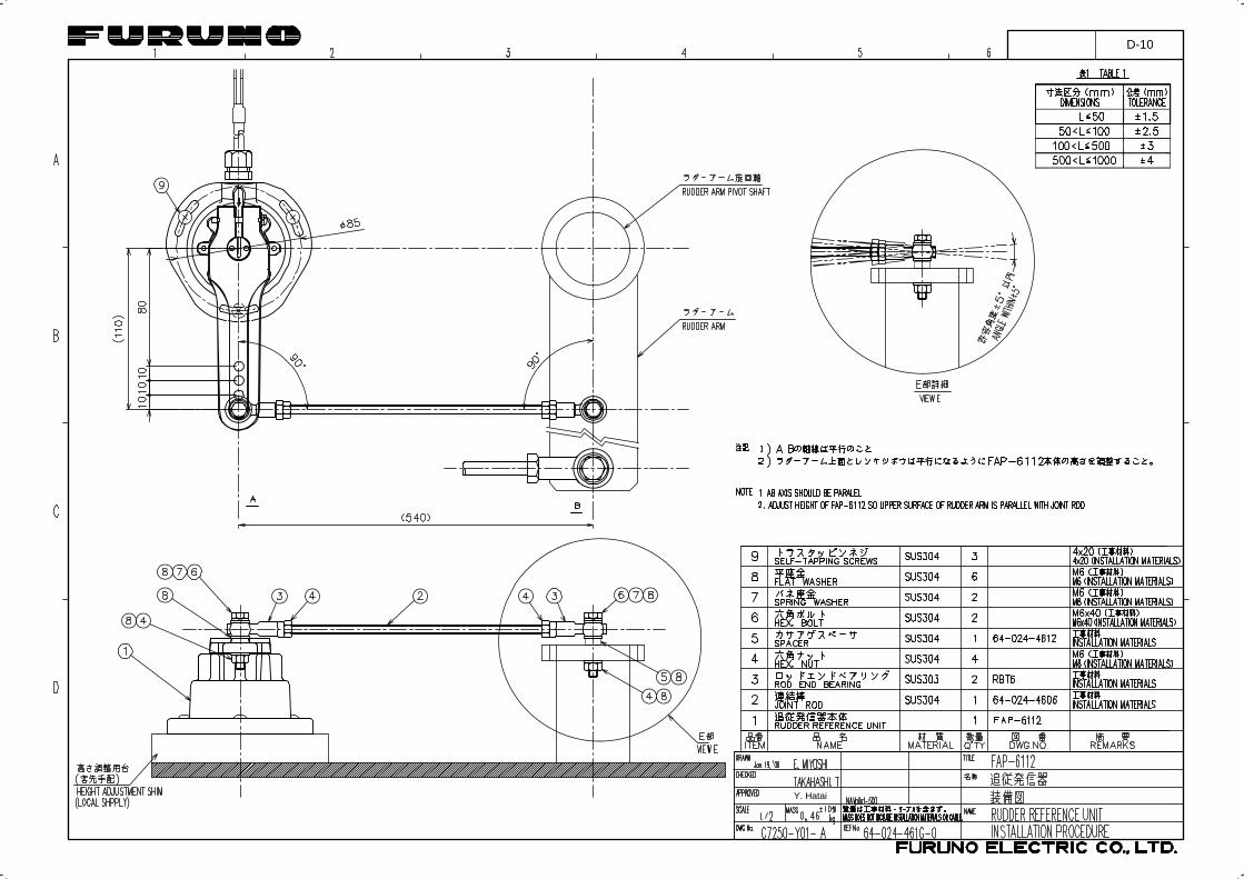
Y. Hatai
D-10
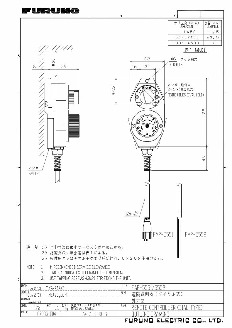


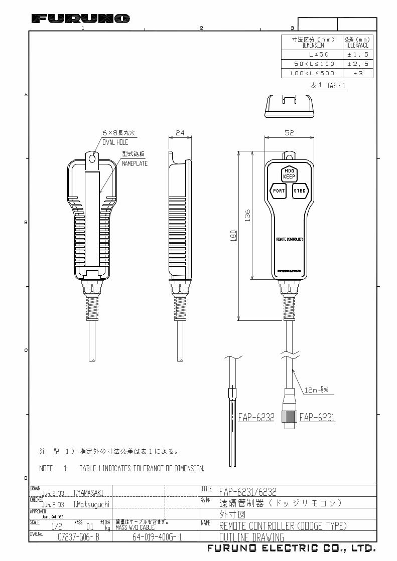
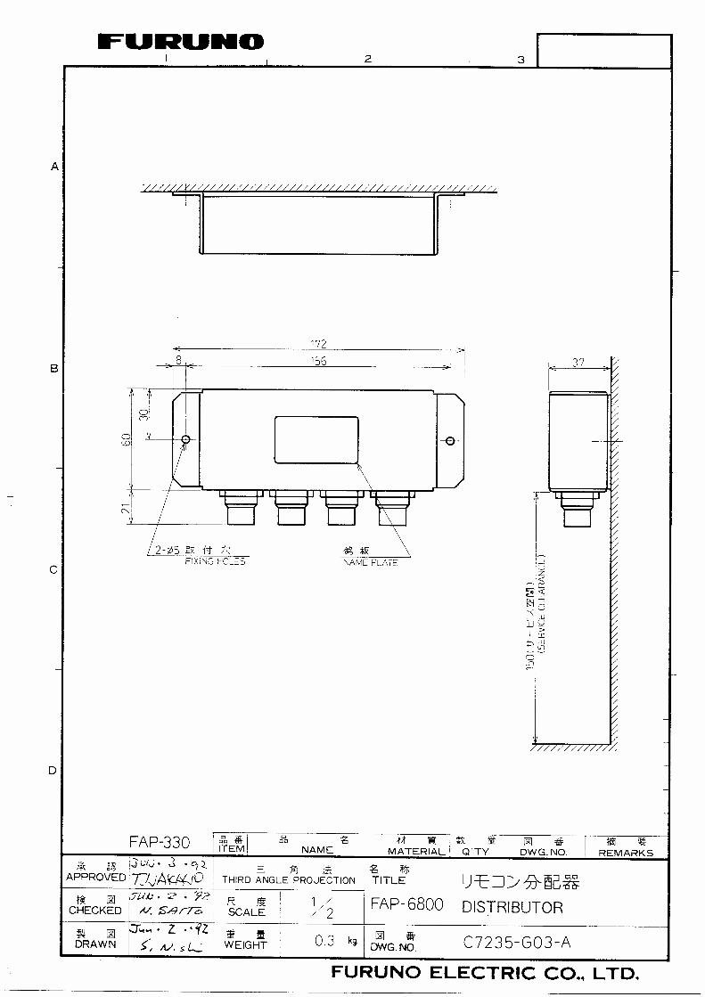
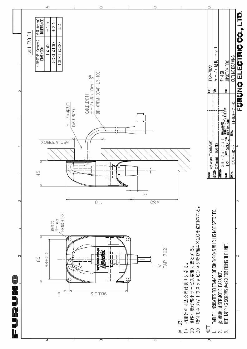
25/Jan/10 R.Esumi

9/Mar/2011 Y.NISHIYAMA
S-1
西山義浩
電子署名者 :西山義浩DN : cn=西山義浩, o, ou=情技課, [email protected], c=JP - 日本日付 : 2011.03.09 14:09:00 +09'00'
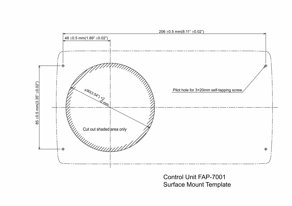
φ90(3.54”) +2
-0 mm
Cut out shaded area only
Pilot hole for 3×20mm self-tapping screw.
Control Unit FAP-7001Surface Mount Template
206 ±0.5 mm(8.11” ±0.02”)
48 ±0.5 mm(1.89” ±0.02”)85
±0.
5 m
m(3
.35”
±0.
02”)

Cut out shaded area only
Drill hole of 10mm(0.39”) in dia.
228 ±0.5 mm(8.98” ±0.02”)
218 ±1 mm(8.58” ±0.04”)
Pilot hole for 3×20mm self-tapping screw.
113 ±1
mm
(4.4
5” ±
0.04
”)
60 ±
0.5
mm
(2.3
6” ±
0.02
”)
103
mm
(4.0
6”)
208 mm(8.19”)
Control Unit FAP-7001Flush Mount Template

80 ±0.5 mm(3.15” ±0.02”)
51.5
mm
(2.0
3”)
94 ±
0.5
mm
(3.7
0” ±
0.02
”) 45
±0.
5 m
m(1
.77”
±0.
02”)
44
.6 ±
0.5
mm
(1.7
6” ±
0.02
”)
60 ±0.5 mm(2.36”±0.02”)
Cut out shaded area only
Drill hole of 3.5 mm(0.14”)in dia.
Pilot hole for 3×20 mmself-tapping screw.
Control Unit FAP-7011Surface Mount Template
96 ±0.5 mm(3.78” ±0.02”)
φ90 (3.54”) +2
-0 mm
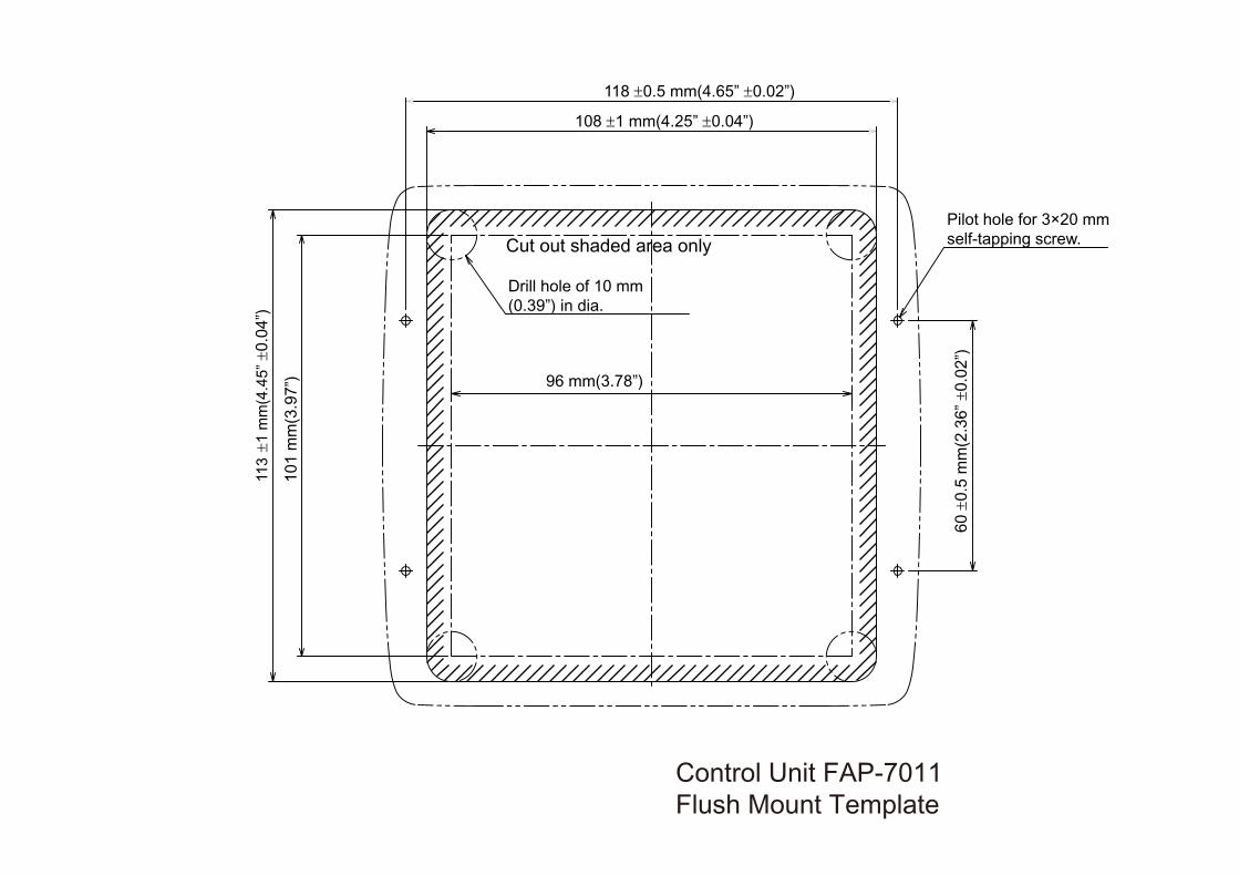
Cut out shaded area only
96 mm(3.78”)
113
±1
mm
(4.4
5” ±
0.04
”)
101
mm
(3.9
7”)
Drill hole of 10 mm(0.39”) in dia.
Pilot hole for 3×20 mmself-tapping screw.
Control Unit FAP-7011Flush Mount Template
118 ±0.5 mm(4.65” ±0.02”)
108 ±1 mm(4.25” ±0.04”)
60 ±
0.5
mm
(2.3
6” ±
0.02
”)