av widgets avw17 dual channel low pass filteravwidgets.com/avwidgets/manuals/avw17 manual.pdf ·...
TRANSCRIPT
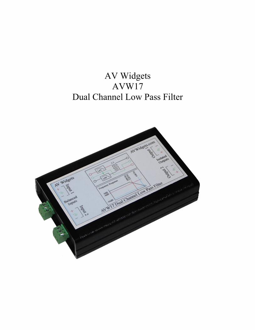
AV WidgetsAVW17
Dual Channel Low Pass Filter
Title: AVW17Date: 12.20.2015Firmware: N/AHardware: PCB-107 Rev. 0
Description
The AVW17 is a dual channel low pass filter that is used in testing qualification of digital amplifiers and digital audio equipment. The AVW17 is designed to be placed between the audiodevice under test and measurement equipment. Balanced to single-ended conversion is also provided.
Features
* Dual channel* All passive design. No added noise or distortion* 20 Hz to 20KHz +/- 3.0dB (typical)* Inexpensive* Stop-band attenuation -56dB @ 44KHz* 100V Maximum Input* Eliminates the need for differential scope probes
Background
Recently, many new audio amplifiers have been incorporating:
* Digital switching technology* BTL (Bridge Tied Load) or differential output
These two technologies present challenges to audio measurement.
Digital switching technology can result in much improved amplifier efficiencies and lower cost. However, these switching technologies (Class D or Switch Mode) typically present out-of-band switching noise at the speaker. Switching noise may not be audible, however, it can make audio measurements difficult. The AVW17 is designed to have minimal impact on the audio signal and reject out-of-band signals.
BTL outputs of amplifiers are also becoming more common. BTL Amplifier outputs are not ground referenced. In a classic linear amplifier, the negative (black terminal) is typically referenced to ground, in a BTL amplifier, this may not be the case. Attaching a single-ended measurement probe to a BTL output can yield odd results, possibility of shutting down the amplifier or even damaging it. An expensive differential probe is typically required to examine BTL amplifier outputs.
Theory
The Audio Engineering Society has published a standard AES17-1998 which describes characteristics of a standard filter for measuring switching amplifiers. The AES17 document describes a filter with a pass-band response of 10Hz to 20KHz +/- 0.1dB and a stop-band attenuation of 60dB at 24KHz. This is a very difficult and expensive filter to realize. AV Widgets has chosen to implement a cost effective solution that is close to the AES17 specification without Abreaking the bank@. The AVW17 realizes 56dB of attenuation at 44KHz.
Other low cost solutions may choose to implement the AES17 filter with operational amplifier (active) designs. These active designs suffer from several issues such as:
* Unable to handle high voltage input signals without resistive scaling.* Addition of distortion* Addition of noise, lowering signal to noise ratio* Requirement of external power
The AVW17 is an all passive design, which results in no added distortion or noise to the signal under test.
Connections
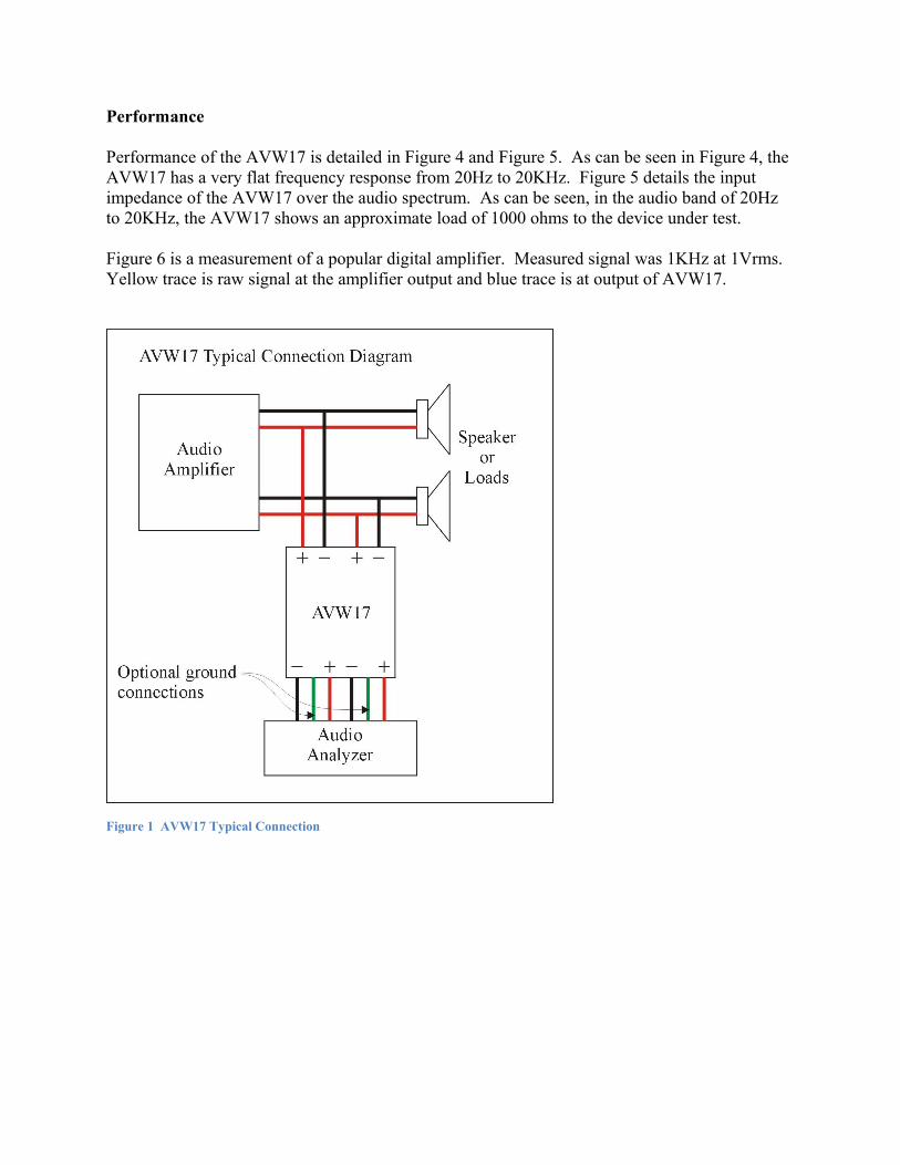
The AVW17 is intended to be connected in parallel with the speaker or load. In other words, thesignal from the amplifier to speaker does not “flow through” the AVW17. The AVW17 is a low current device, the output of the AVW17 is typically only connected to a measurement device such as an oscilloscope or audio analyzer.
Input Connection. Note that the connections of the amplifier to the AVW17. The amplifier’s positive (RED) output is connected to the + Input. The amplifier’s negative (BLACK) output is connected to the – Input.
Output Connection. The AVW17 converts a BTL (differential) output from an amplifier to an unbalanced output. It can also provide electrical isolation. A typical connection to an audio analyzer is shown in Figure 1. Oscilloscope connection would attach the oscilloscope’s ground to the - Output and probe tip to + Output. A typical connection to an oscilloscope is shown in Figure 3.
Connections and operational block diagrams are detailed on the label of the AVW17, shown in Figure 2.
Performance
Performance of the AVW17 is detailed in Figure 4 and Figure 5. As can be seen in Figure 4, the AVW17 has a very flat frequency response from 20Hz to 20KHz. Figure 5 details the input impedance of the AVW17 over the audio spectrum. As can be seen, in the audio band of 20Hz to 20KHz, the AVW17 shows an approximate load of 1000 ohms to the device under test.
Figure 6 is a measurement of a popular digital amplifier. Measured signal was 1KHz at 1Vrms. Yellow trace is raw signal at the amplifier output and blue trace is at output of AVW17.
Figure 1 AVW17 Typical Connection
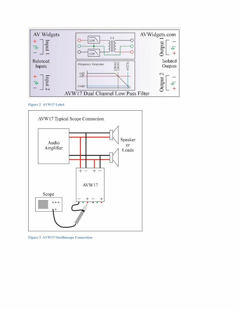
Figure 2 AVW17 Label
Figure 3 AVW17 Oscilloscope Connection
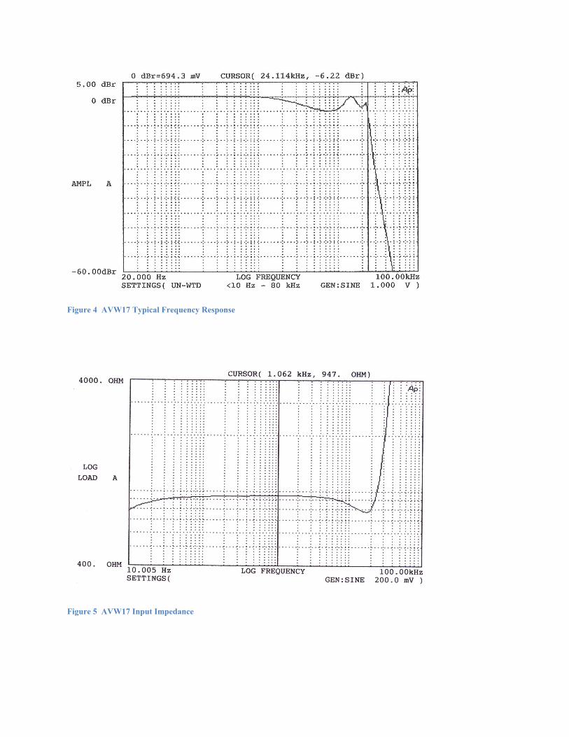
Figure 4 AVW17 Typical Frequency Response
Figure 5 AVW17 Input Impedance
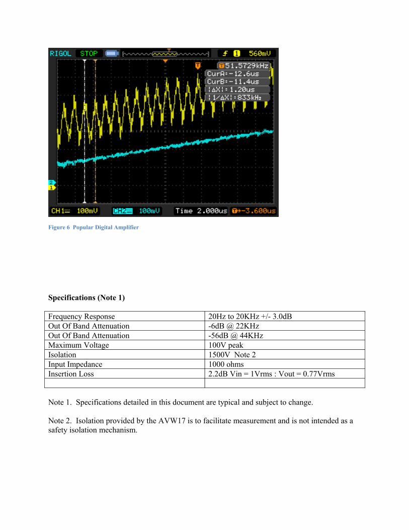
Figure 6 Popular Digital Amplifier
Specifications (Note 1)
Frequency Response 20Hz to 20KHz +/- 3.0dBOut Of Band Attenuation -6dB @ 22KHzOut Of Band Attenuation -56dB @ 44KHzMaximum Voltage 100V peakIsolation 1500V Note 2Input Impedance 1000 ohmsInsertion Loss 2.2dB Vin = 1Vrms : Vout = 0.77Vrms
Note 1. Specifications detailed in this document are typical and subject to change.
Note 2. Isolation provided by the AVW17 is to facilitate measurement and is not intended as a safety isolation mechanism.