available transfer capability definitions and … capability is the amount of transfer capability...
TRANSCRIPT
AvailableTransfer Capability
Definitions and Determination
A framework fordetermining available transfer capabilities
of the interconnected transmission networksfor a commercially viable
electricity market
North American Electric Reliability Council
June 1996

CONTENTS
NERC Available Transfer Capability Definitions and Determination
EXECUTIVE SUMMARY . . . . . . . . . . . . . . . . . . . . . . . . . . . . . . . . . . . . . . . . . . . . . . . . . . . . . . . . . . . . . 1
INTRODUCTION . . . . . . . . . . . . . . . . . . . . . . . . . . . . . . . . . . . . . . . . . . . . . . . . . . . . . . . . . . . . . . . . . . . 4Background . . . . . . . . . . . . . . . . . . . . . . . . . . . . . . . . . . . . . . . . . . . . . . . . . . . . . . . . . . . . . . . . . . 4Terminology Convention . . . . . . . . . . . . . . . . . . . . . . . . . . . . . . . . . . . . . . . . . . . . . . . . . . . . . . . . 4NERC Strategic Initiative . . . . . . . . . . . . . . . . . . . . . . . . . . . . . . . . . . . . . . . . . . . . . . . . . . . . . . . . 4Purpose of This Report . . . . . . . . . . . . . . . . . . . . . . . . . . . . . . . . . . . . . . . . . . . . . . . . . . . . . . . . . . 5
AVAILABLE TRANSFER CAPABILITY PRINCIPLES . . . . . . . . . . . . . . . . . . . . . . . . . . . . . . . . . . . . . . . 6
TRANSMISSION TRANSFER CAPABILITY CONCEPTS . . . . . . . . . . . . . . . . . . . . . . . . . . . . . . . . . . . . . 7Transfer Capability . . . . . . . . . . . . . . . . . . . . . . . . . . . . . . . . . . . . . . . . . . . . . . . . . . . . . . . . . . . . . 7Transfer Capability versus Transmission Capacity . . . . . . . . . . . . . . . . . . . . . . . . . . . . . . . . . . . . . 7Determination of Transfer Capability . . . . . . . . . . . . . . . . . . . . . . . . . . . . . . . . . . . . . . . . . . . . . . . 7Limits to Transfer Capability . . . . . . . . . . . . . . . . . . . . . . . . . . . . . . . . . . . . . . . . . . . . . . . . . . . . . 8Uses of Transmission Systems . . . . . . . . . . . . . . . . . . . . . . . . . . . . . . . . . . . . . . . . . . . . . . . . . . . . 9
TTC DEFINITION AND DETERMINATION . . . . . . . . . . . . . . . . . . . . . . . . . . . . . . . . . . . . . . . . . . . . . . 10Definition of Total Transfer Capability . . . . . . . . . . . . . . . . . . . . . . . . . . . . . . . . . . . . . . . . . . . . 10Determination of Total Transfer Capability . . . . . . . . . . . . . . . . . . . . . . . . . . . . . . . . . . . . . . . . . 10
System Conditions . . . . . . . . . . . . . . . . . . . . . . . . . . . . . . . . . . . . . . . . . . . . . . . . . . . . . . . . . 10Critical Contingencies . . . . . . . . . . . . . . . . . . . . . . . . . . . . . . . . . . . . . . . . . . . . . . . . . . . . . . 11System Limits . . . . . . . . . . . . . . . . . . . . . . . . . . . . . . . . . . . . . . . . . . . . . . . . . . . . . . . . . . . . 11Parallel Path Flows . . . . . . . . . . . . . . . . . . . . . . . . . . . . . . . . . . . . . . . . . . . . . . . . . . . . . . . . 12Non-Simultaneous and Simultaneous Transfers . . . . . . . . . . . . . . . . . . . . . . . . . . . . . . . . . . . 12
TRANSMISSION TRANSFER CAPABILITY MARGINS . . . . . . . . . . . . . . . . . . . . . . . . . . . . . . . . . . . . . 13Technical Basis . . . . . . . . . . . . . . . . . . . . . . . . . . . . . . . . . . . . . . . . . . . . . . . . . . . . . . . . . . . . . . 13Definition of Transmission Reliability Margin . . . . . . . . . . . . . . . . . . . . . . . . . . . . . . . . . . . . . . . 13
Uncertainty in TTC and ATC Calculations . . . . . . . . . . . . . . . . . . . . . . . . . . . . . . . . . . . . . . 14Need for Operating Flexibility . . . . . . . . . . . . . . . . . . . . . . . . . . . . . . . . . . . . . . . . . . . . . . . . 14
Definition of Capacity Benefit Margin . . . . . . . . . . . . . . . . . . . . . . . . . . . . . . . . . . . . . . . . . . . . . 14
ATC DEFINITION AND DETERMINATION . . . . . . . . . . . . . . . . . . . . . . . . . . . . . . . . . . . . . . . . . . . . . . 15Definition of Available Transfer Capability . . . . . . . . . . . . . . . . . . . . . . . . . . . . . . . . . . . . . . . . . 15Determination of Available Transfer Capability . . . . . . . . . . . . . . . . . . . . . . . . . . . . . . . . . . . . . . 15Commercial Components of Available Transfer Capability . . . . . . . . . . . . . . . . . . . . . . . . . . . . . 15
Curtailability . . . . . . . . . . . . . . . . . . . . . . . . . . . . . . . . . . . . . . . . . . . . . . . . . . . . . . . . . . . . . 16Recallability . . . . . . . . . . . . . . . . . . . . . . . . . . . . . . . . . . . . . . . . . . . . . . . . . . . . . . . . . . . . . . 16
Recallable and Non-recallable Relationships and Priorities . . . . . . . . . . . . . . . . . . . . . . . . . . . . . 18Scheduled and Reserved Transmission Service . . . . . . . . . . . . . . . . . . . . . . . . . . . . . . . . . . . 18Transmission Service Priorities . . . . . . . . . . . . . . . . . . . . . . . . . . . . . . . . . . . . . . . . . . . . . . . 19
Appendix A. NETWORK RESPONSE METHOD FOR ATC DETERMINATION . . . . . . . . . . . . . . . . 22
Appendix B. RATED SYSTEM PATH METHOD FOR ATC DETERMINATION . . . . . . . . . . . . . . . . 29
Appendix C. TRANSMISSION SERVICE RESERVATIONS AND SCHEDULING . . . . . . . . . . . . . . . . 35
TRANSMISSION TRANSFER CAPABILITY TASK FORCE . . . . . . . . . . . . . . . . . . . . . . . . . . . . . . . . . . 40
EXECUTIVE SUMMARY
Available Transfer Capability Definitions and Determination NERC 1
This report, Available Transfer Capability Definitions and Determination, is in response to a NERCStrategic Initiative to “develop uniform definitions for determining Available (Transmission) TransferCapability (ATC) and related terms that satisfy both [Federal Energy Regulatory Commission] FERC andelectric industry needs, and which are to be implemented throughout the industry.” The NERC Board ofTrustees at its May 13–14, 1996 meeting approved this report and endorsed its use by all segments of theelectric industry.
The report establishes a framework for determining ATCs of the interconnected transmission networks fora commercially viable wholesale electricity market. The report also defines the ATC Principles underwhich ATC values are to be calculated. It is non-prescriptive in that it permits individual systems, powerpools, subregions, and Regions to develop their own procedures for determining or coordinating ATCsbased on a regional or wide-area approach in accordance with the Principles defined herein. The proposedATC calculation framework is based on the physical and electrical characteristics and capabilities of theinterconnected networks as applicable under NERC, Regional, subregional, power pool, and individualsystem reliability planning and operating policies, criteria, or guides.
This report provides an initial framework on ATC that will likely be expanded and modified as experienceis gained in its use and as more is learned about how the competitive electric power market will function. The U.S. Federal Energy Regulatory Commission’s final rules, Orders No. 888 and No. 889 pertaining topromoting wholesale competition through open access non-discriminatory transmission services by publicutilities and an open access same-time information system, respectively, were issued April 24, 1996. Theframework for the determination of ATC as outlined in this report is in accord with the key provisions ofthese rulemakings.
ATC PRINCIPLES
The following Available Transfer Capability (ATC) Principles govern the development of the definitionand determination of ATC and related terms. All transmission provider and user entities are expected toabide by these Principles.
1. ATC calculations must produce commercially viable results. ATCs produced by the calculationsmust give a reasonable and dependable indication of transfer capabilities available to the electricpower market.
2. ATC calculations must recognize time-variant power flow conditions on the entire interconnectedtransmission network. In addition, the effects of simultaneous transfers and parallel path flowsthroughout the network must be addressed from a reliability viewpoint.
3. ATC calculations must recognize the dependency of ATC on the points of electric power injection,the directions of transfers across the interconnected transmission network, and the points of powerextraction. All entities must provide sufficient information necessary for the calculation of ATC.
4. Regional or wide-area coordination is necessary to develop and post information that reasonablyreflects the ATCs of the interconnected transmission network.

EXECUTIVE SUMMARY
2 NERC Available Transfer Capability Definitions and Determination
5. ATC calculations must conform to NERC, Regional, subregional, power pool, and individualsystem reliability planning and operating policies, criteria, or guides.
6. The determination of ATC must accommodate reasonable uncertainties in system conditions andprovide operating flexibility to ensure the secure operation of the interconnected network.
The calculation of transfer capability is generally based on computer simulations of the operation of theinterconnected transmission network under a specific set of assumed operating conditions. These simu-lations are typically performed “off line,” well before the systems approach that operational state. Eachsimulation represents a single “snapshot” of the operation of the interconnected network based on theprojections of many factors. As such, they are viewed as reasonable indicators of network performance andavailable transfer capability.
ATC DEFINITIONS
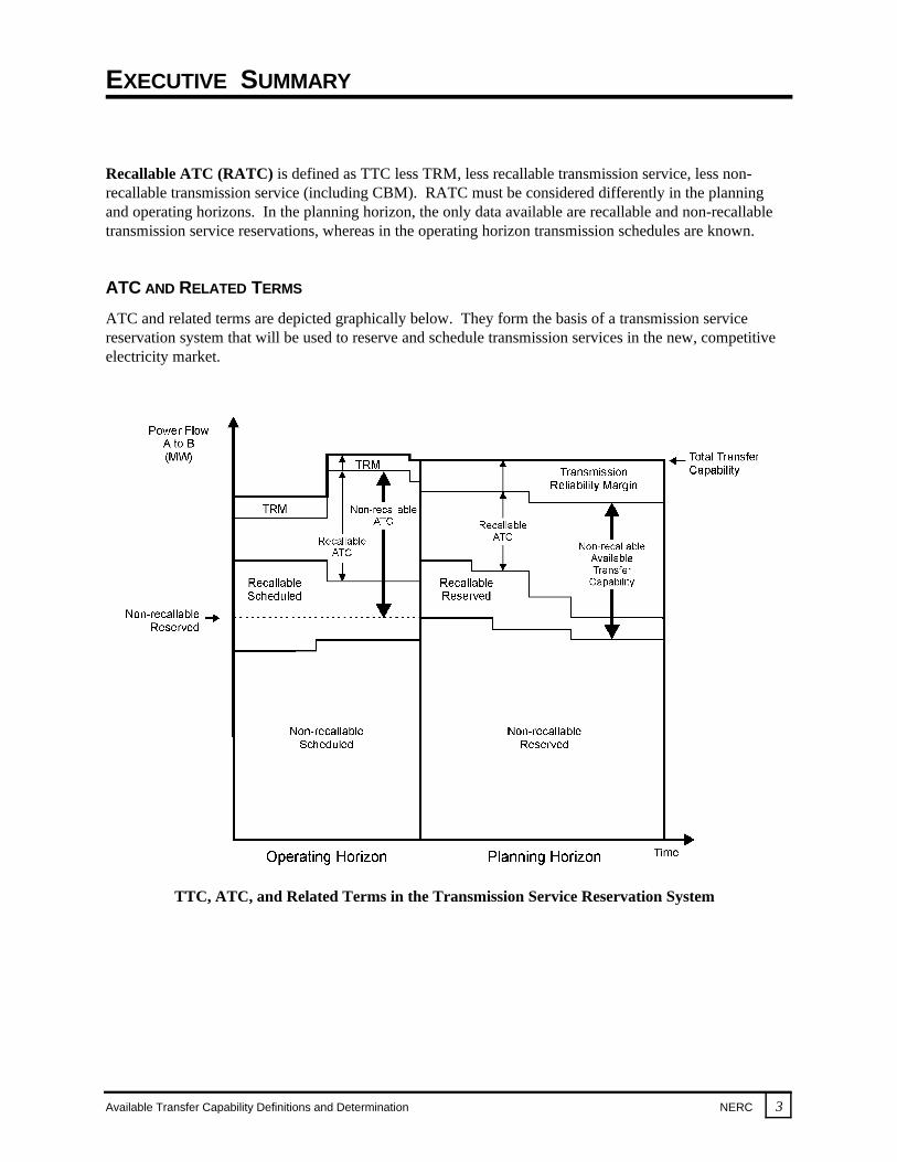
Available Transfer Capability (ATC) is a measure of the transfer capability remaining in the physicaltransmission network for further commercial activity over and above already committed uses. Mathe-matically, ATC is defined as the Total Transfer Capability (TTC) less the Transmission Reliability Margin(TRM), less the sum of existing transmission commitments (which includes retail customer service) and theCapacity Benefit Margin (CBM).
Total Transfer Capability (TTC) is defined as the amount of electric power that can be trans-ferred over the interconnected transmission network in a reliable manner while meeting all of aspecific set of defined pre- and post-contingency system conditions.
Transmission Reliability Margin (TRM) is defined as that amount of transmission transfercapability necessary to ensure that the interconnected transmission network is secure under areasonable range of uncertainties in system conditions.
Capacity Benefit Margin (CBM) is defined as that amount of transmission transfer capabilityreserved by load serving entities to ensure access to generation from interconnected systems tomeet generation reliability requirements.
Curtailability is defined as the right of a transmission provider to interrupt all or part of a transmissionservice due to constraints that reduce the capability of the transmission network to provide that trans-mission service. Transmission service is to be curtailed only in cases where system reliability is threatenedor emergency conditions exist.
Recallability is defined as the right of a transmission provider to interrupt all or part of a transmissionservice for any reason, including economic, that is consistent with FERC policy and the transmissionprovider’s transmission service tariffs or contract provisions.
Non-recallable ATC (NATC) is defined as TTC less TRM, less non-recallable reserved transmissionservice (including CBM).
EXECUTIVE SUMMARY
Available Transfer Capability Definitions and Determination NERC 3
TTC, ATC, and Related Terms in the Transmission Service Reservation System
Recallable ATC (RATC) is defined as TTC less TRM, less recallable transmission service, less non-recallable transmission service (including CBM). RATC must be considered differently in the planningand operating horizons. In the planning horizon, the only data available are recallable and non-recallabletransmission service reservations, whereas in the operating horizon transmission schedules are known.
ATC AND RELATED TERMS
ATC and related terms are depicted graphically below. They form the basis of a transmission servicereservation system that will be used to reserve and schedule transmission services in the new, competitiveelectricity market.
INTRODUCTION
4 NERC Available Transfer Capability Definitions and Determination
BACKGROUND
Available Transmission Capacity as described in the U.S. Federal Energy Regulatory Commission’s(FERC) March 29, 1995 Notice of Proposed Rulemaking (NOPR), Docket RM95-8-000, Section III-E4f,is a new term that has not been universally defined or used by the electric industry. The electric industryhas historically used other standard terms, techniques, and methodologies to define and calculate mean-ingful measures of the transmission transfer capability of the interconnected transmission networks. Theseterms, which include First Contingency Total Transfer Capability (FCTTC) and First Contingency Incre-mental Transfer Capability (FCITC) as defined in NERC’s May 1995 Transmission Transfer Capabilityreference document, are still applicable measures in an open transmission access environment. FERC’sterm Available Transmission Capacity and its definition and relationship to the industry’s terminology needto be further clarified.
In its NOPR, FERC also requires that Available Transmission Capacity information be made available on apublicly accessible Real-time Information Network (RIN). Definitions of Available Transmission Capacityin the report of the industry’s Electronic Information Network “What” Working Group, which was filedwith FERC on October 16, 1995, are only considered to be assumptions to support the Working Group’seffort in determining what information should be included on RINs. This report further refines thosedefinitions.
It must be noted early in this report that electric systems in Canada and the northern portion of BajaCalifornia, Mexico, which are electrically interconnected with electric systems in the United States, areactive members in NERC and the Regional Councils and are committed to promoting and maintaininginterconnected electric system reliability. These non-U.S. systems are not, however, subject to FERCjurisdiction, and the commercial aspects of the definitions contained herein are not necessarily applicable tothe operation of their internal transmission systems.
TERMINOLOGY CONVENTION
FERC used the term Available Transmission Capacity in its NOPR to label the information that is to bemade accessible to all transmission users as an indication of the available capability of the interconnectedtransmission networks to support additional transmission service. To avoid confusion with individualtransmission line capacities or ratings, all references to “ATC” throughout this report will refer to Avail-able (Transmission) Transfer Capability and its related terms as defined in this report.
NERC STRATEGIC INITIATIVE
One of several Strategic Initiatives for NERC, approved by the NERC Board of Trustees on October 3,1995, is to “develop uniform definitions for determining Available (Transmission) Transfer Capability andrelated terms that satisfy both FERC and electric industry needs, and which are to be implementedthroughout the industry.” The then existing NERC Transmission Transfer Capability Task Force, with ex-panded membership to include all segments of the electric industry, was assigned this responsibility forcompletion in May 1996.
INTRODUCTION
Available Transfer Capability Definitions and Determination NERC 5
PURPOSE OF THIS REPORT
This report is the response to NERC’s Strategic Initiative on ATC and defines ATC and related terms. From a commercial perspective, the key element in the development of uniform definitions for transmissiontransfer capability is the amount of transfer capability that is available at a given time for purchase or salein the electric power market under various system conditions. Open access to the transmission systemsplaces a new emphasis on the use of the interconnected networks. As such, future electric power transfersare anticipated to increase over a wide range of system conditions, making the reliable operation of thetransmission networks more complex. To effectively maintain system reliability, those who calculate,report, post, and use this information must all have the same understanding of its meaning for commercialuse. To accomplish this purpose, this report will answer the following questions:
– What is ATC?– How does ATC relate to industry standard terminology?– What physical factors need to be considered in determining ATC?– What reliability issues must be considered in determining ATC?– How is ATC calculated?– How will ATC be commercially used?
The report establishes a framework for determining the ATCs of the interconnected transmission networksfor a commercially viable electricity market. Although the report defines the ATC Principles under whichATCs are to be calculated, it is non-prescriptive in that it permits individual systems, power pools, sub-regions, and Regions to develop their own procedures for determining or coordinating ATCs based on aregional or wide-area approach in accordance with these Principles.
The report does not address transmission ownership and equity issues, nor does it address the allocation oftransmission services or ATC values. The calculation of ATC is based strictly on the physical and elec-trical characteristics and capabilities of the interconnected networks as applicable under NERC, Regional,subregional, power pool, and individual system reliability planning and operating policies, criteria, orguides.
As the competitive electric power market develops, more will be learned on how these markets will functionand how the definitions of ATC will be used. This report provides an initial framework on ATC, whichwill likely be expanded and modified as experience is gained in its use. The U.S. Federal EnergyRegulatory Commission’s final rules, Orders No. 888 and No. 889 pertaining to promoting wholesalecompetition through open access non-discriminatory transmission services by public utilities and an openaccess same-time information system, respectively, were issued April 24, 1996. The framework for thedetermination of ATC as outlined in this report is in accord with the key provisions of these rulemakings.
AVAILABLE TRANSFER CAPABILITY PRINCIPLES
6 NERC Available Transfer Capability Definitions and Determination
ATC PRINCIPLES
Available Transfer Capability (ATC) is a measure of the transfer capability remaining in the physicaltransmission network for further commercial activity over and above already committed uses. As ameasure bridging the technical characteristics of how interconnected transmission networks perform tothe commercial requirements associated with transmission service requests, ATC must satisfy certainprinciples balancing both technical and commercial issues. ATC must accurately reflect the physicalrealities of the transmission network, while not being so complicated that it unduly constrains commerce. The following principles identify the requirements for the calculation and application of ATCs.
1. ATC calculations must produce commercially viable results. ATCs produced by the calcu-lations must give a reasonable and dependable indication of transfer capabilities available tothe electric power market. The frequency and detail of individual ATC calculations must beconsistent with the level of commercial activity and congestion.
2. ATC calculations must recognize time-variant power flow conditions on the entire intercon-nected transmission network. In addition, the effects of simultaneous transfers and parallelpath flows throughout the network must be addressed from a reliability viewpoint. Regardlessof the desire for commercial simplification, the laws of physics govern how the transmissionnetwork will react to customer demand and generation supply. Electrical demand and supplycannot, in general, be treated independently of one another. All system conditions, uses, and limitsmust be considered to accurately assess the capabilities of the transmission network.
3. ATC calculations must recognize the dependency of ATC on the points of electric powerinjection, the directions of transfers across the interconnected transmission network, and thepoints of power extraction. All entities must provide sufficient information necessary for thecalculation of ATC. Electric power flows resulting from each power transfer use the entirenetwork and are not governed by the commercial terms of the transfer.
4. Regional or wide-area coordination is necessary to develop and post information that reason-ably reflects the ATCs of the interconnected transmission network. ATC calculations must usea regional or wide-area approach to capture the interactions of electric power flows amongindividual, subregional, Regional, and multiregional systems.
5. ATC calculations must conform to NERC, Regional, subregional, power pool, and individualsystem reliability planning and operating policies, criteria, or guides. Appropriate system con-tingencies must be considered.
6. The determination of ATC must accommodate reasonable uncertainties in system conditionsand provide operating flexibility to ensure the secure operation of the interconnected net-work. A Transmission Reliability Margin (TRM) may be necessary to apply this Principle. Additionally, transmission capability (defined as Capacity Benefit Margin or CBM) may need tobe reserved to meet generation reliability requirements.

TRANSMISSION TRANSFER CAPABILITY CONCEPTS
Available Transfer Capability Definitions and Determination NERC 7
The key basic concepts of transmission transfer capability are described below. Numerous other termsrelated to transfer capability are explored in detail in NERC’s May 1995 Transmission TransferCapability reference document. The concepts and terms in that document are still applicable in an opentransmission environment.
TRANSFER CAPABILITY
Transfer capability is the measure of the ability of interconnected electric systems to reliably move ortransfer power from one area to another over all transmission lines (or paths) between those areas underspecified system conditions. The units of transfer capability are in terms of electric power, generallyexpressed in megawatts (MW). In this context, “area” may be an individual electric system, power pool,control area, subregion, or NERC Region, or a portion of any of these. Transfer capability is also direc-tional in nature. That is, the transfer capability from Area A to Area B is not generally equal to the transfercapability from Area B to Area A.
TRANSFER CAPABILITY VERSUS TRANSMISSION CAPACITY
Electric systems throughout NERC have agreed to use common terminology to calculate and report trans-mission transfer limits to maintain the reliability of the interconnected transmission networks. Thesetransfer values are called “capabilities” (differentiating them from “capacities”) because they are highlydependent on the generation, customer demand, and transmission system conditions assumed during thetime period analyzed. The electric industry generally uses the term “capacity” as a specific limit or ratingof power system equipment. In transmission, capacity usually refers to the thermal limit or rating of aparticular transmission element or component. The ability of a single transmission line to transfer electricpower, when operated as part of the interconnected network, is a function of the physical relationship ofthat line to the other elements of the transmission network.
Individual transmission line capacities or ratings cannot be added to determine the transfer capability of atransmission path or interface (transmission circuits between two or more areas within an electric system orbetween two or more systems). Such aggregated capacity values may be vastly different from the trans-mission transfer capability of the network. Often, the aggregated capacity of the individual circuits of aspecific transmission interface between two areas of the network is greater than the actual transfer capa-bility of that interface. In summary, the aggregated transmission line capacities of a path or interface donot represent the transfer capabilities between two areas.
DETERMINATION OF TRANSFER CAPABILITY
The calculation of transfer capability is generally based on computer simulations of the operation of theinterconnected transmission network under a specific set of assumed operating conditions. These sim-ulations are typically performed “off line,” well before the systems approach that operational state. Eachsimulation represents a single “snapshot” of the operation of the interconnected network based on theprojections of many factors. As such, they are viewed as reasonable indicators of network performance andavailable transfer capability. Among the factors considered in these simulations are:
TRANSMISSION TRANSFER CAPABILITY CONCEPTS
8 NERC Available Transfer Capability Definitions and Determination
€ Projected Customer Demands — Base case demand levels should be appropriate to the systemconditions and customer demand levels under study and may be representative of peak,off-peak or shoulder, or light demand conditions.
€ Generation Dispatch — Utility and nonutility generators should be realistically dispatched forthe system conditions being simulated.
€ System Configuration — The base case configuration of the interconnected systems should berepresentative of the conditions being simulated, including any generation and transmissionoutages that are expected. The activation of any operating procedures normally expected to bein effect should also be included in the simulations.
€ Base Scheduled Transfers — The scheduled electric power transfers that should be modeledare those that are generally considered to be representative of the base system conditions beinganalyzed and which are agreed upon by the parties involved.
€ System Contingencies — A significant number of generation and transmission system contin-gencies should be screened, consistent with individual electric system, power pool,subregional, and Regional planning criteria or guides, to ensure that the facility outage mostrestrictive to the transfer being studied is identified and analyzed. The contingencies evaluatedmay in some instances include multiple contingencies where deemed to be appropriate.
The conditions on the interconnected network continuously vary in real time. Therefore, the transfer capa-bility of the network will also vary from one instant to the next. For this reason, transfer capability calcu-lations may need to be updated periodically for application in the operation of the network. In addition,depending on actual network conditions, transfer capabilities can often be higher or lower than thosedetermined in the off-line studies. The farther into the future that simulations are projected, the greater isthe uncertainty in assumed conditions. However, transfer capabilities determined from simulation studiesare generally viewed as reasonable indicators of actual network capability.
LIMITS TO TRANSFER CAPABILITY
The ability of interconnected transmission networks to reliably transfer electric power may be limited bythe physical and electrical characteristics of the systems including any one or more of the following:
€ Thermal Limits — Thermal limits establish the maximum amount of electrical current that atransmission line or electrical facility can conduct over a specified time period before itsustains permanent damage by overheating or before it violates public safety requirements.
€ Voltage Limits — System voltages and changes in voltages must be maintained within therange of acceptable minimum and maximum limits. For example, minimum voltage limits canestablish the maximum amount of electric power that can be transferred without causingdamage to the electric system or customer facilities. A widespread collapse of system voltagecan result in a blackout of portions or all of the interconnected network.
TRANSMISSION TRANSFER CAPABILITY CONCEPTS
Available Transfer Capability Definitions and Determination NERC 9
€ Stability Limits — The transmission network must be capable of surviving disturbancesthrough the transient and dynamic time periods (from milliseconds to several minutes, respec-tively) following the disturbance. All generators connected to ac interconnected transmissionsystems operate in synchronism with each other at the same frequency (nominally 60 Hertz). Immediately following a system disturbance, generators begin to oscillate relative to eachother, causing fluctuations in system frequency, line loadings, and system voltages. For thesystem to be stable, the oscillations must diminish as the electric systems attain a new, stableoperating point. If a new, stable operating point is not quickly established, the generators willlikely lose synchronism with one another, and all or a portion of the interconnected electricsystems may become unstable. The results of generator instability may damage equipment andcause uncontrolled, widespread interruption of electric supply to customers.
The limiting condition on some portions of the transmission network can shift among thermal, voltage, andstability limits as the network operating conditions change over time. Such variations further complicatethe determination of transfer capability limits.
USES OF TRANSMISSION SYSTEMS
The interconnected transmission networks tie together major electric system facilities, generation resources,and customer demand centers. They are planned, designed, and constructed to operate reliably withinthermal, voltage, and stability limits for the following purposes:
€ To Deliver Electric Power to Customers — Transmission networks must provide for thereliable transfer of the electric power output from generation resources to customers under awide variety of operating conditions.
€ To Provide Flexibility for Changing System Conditions — Transmission capability must beavailable on the interconnected network to provide flexibility to reliably handle the shift intransmission facility loadings caused by maintenance and forced outages of generation andtransmission equipment, and a wide range of variable system conditions, such as higher thanexpected customer demands, or construction delays of new facilities.
€ To Reduce the Need for Installed Generating Capacity — Transmission interconnectionsbetween neighboring systems provide for the sharing of installed generating capacity, takingadvantage of the diversity in customer demands and generation availability over a wide area,thereby reducing the amount of installed generating capacity necessary to meet generationreliability requirements in each of the interconnecting systems.
€ To Allow Economic Exchange of Electric Power Among Systems — Transmission intercon-nections between systems, coupled with internal system transmission facilities, allow for theeconomic exchange of electric power among neighboring systems. Such economy transfershelp reduce the overall cost of electricity to customers.
TTC DEFINITION AND DETERMINATION
10 NERC Available Transfer Capability Definitions and Determination
DEFINITION OF TOTAL TRANSFER CAPABILITY
The Total Transfer Capability (TTC) between any two areas or across particular paths or interfaces isdirection specific and consistent with the First Contingency Total Transfer Capability (FCTTC) as definedin NERC’s May 1995 Transmission Transfer Capability reference document.
TTC is the amount of electric power that can be transferred over the interconnected transmission networkin a reliable manner based on all of the following conditions:
1. For the existing or planned system configuration, and with normal (pre-contingency) operatingprocedures in effect, all facility loadings are within normal ratings and all voltages are withinnormal limits.
2. The electric systems are capable of absorbing the dynamic power swings, and remaining stable,following a disturbance that results in the loss of any single electric system element, such as atransmission line, transformer, or generating unit.
3. After the dynamic power swings subside following a disturbance that results in the loss of anysingle electric system element as described in 2 above, and after the operation of any automaticoperating systems, but before any post-contingency operator-initiated system adjustments areimplemented, all transmission facility loadings are within emergency ratings and all voltages arewithin emergency limits.
4. With reference to condition 1 above, in the case where pre-contingency facility loadings reachnormal thermal ratings at a transfer level below that at which any first contingency transfer limitsare reached, the transfer capability is defined as that transfer level at which such normal ratings arereached.
5. In some cases, individual system, power pool, subregional, or Regional planning criteria or guidesmay require consideration of specified multiple contingencies, such as the outage of transmissioncircuits using common towers or rights-of-way, in the determination of transfer capability limits. If the resulting transfer limits for these multiple contingencies are more restrictive than the singlecontingency considerations described above, the more restrictive reliability criteria or guides mustbe observed.
DETERMINATION OF TOTAL TRANSFER CAPABILITY
The concepts for determining transfer capability described in NERC’s Transmission Transfer Capabilityreference document are still valid and do not change with the advent of open transmission access or theneed to determine ATCs. The major points contained therein are briefly outlined below.
System ConditionsBase system conditions are identified and modeled for the period being analyzed, including projectedcustomer demands, generation dispatch, system configuration, and base scheduled transfers. Assystem conditions change, the base system conditions under which TTC is calculated may also need tobe modified.
TTC DEFINITION AND DETERMINATION
Available Transfer Capability Definitions and Determination NERC 11
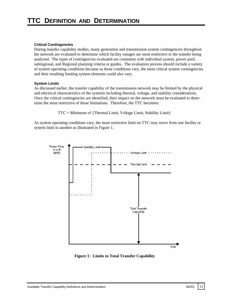
Figure 1: Limits to Total Transfer Capability
Critical ContingenciesDuring transfer capability studies, many generation and transmission system contingencies throughoutthe network are evaluated to determine which facility outages are most restrictive to the transfer beinganalyzed. The types of contingencies evaluated are consistent with individual system, power pool,subregional, and Regional planning criteria or guides. The evaluation process should include a varietyof system operating conditions because as those conditions vary, the most critical system contingenciesand their resulting limiting system elements could also vary.
System LimitsAs discussed earlier, the transfer capability of the transmission network may be limited by the physicaland electrical characteristics of the systems including thermal, voltage, and stability considerations. Once the critical contingencies are identified, their impact on the network must be evaluated to deter-mine the most restrictive of those limitations. Therefore, the TTC becomes:
TTC = Minimum of {Thermal Limit, Voltage Limit, Stability Limit}
As system operating conditions vary, the most restrictive limit on TTC may move from one facility orsystem limit to another as illustrated in Figure 1.
TTC DEFINITION AND DETERMINATION
12 NERC Available Transfer Capability Definitions and Determination
Parallel Path FlowsWhen electric power is transferred across the network, parallel path flows occur. This complex electrictransmission network phenomenon can affect all systems of an interconnected network, especiallythose systems electrically near the transacting systems. As a result, transfer capability determinationsmust be sufficient in scope to ensure that limits throughout the interconnected network are addressed. In some cases, the parallel path flows may result in transmission limitations in systems other than thetransacting systems, which can limit the transfer capability between the two contracting areas.
Non-Simultaneous and Simultaneous TransfersTransfer capability can be determined by simulating transfers from one area to another independentlyand non-concurrently with other area transfers. These capabilities are referred to as “non-simul-taneous” transfers. Another type of transfer capability reflects simultaneous or multiple transfersconcurrently. These capabilities are developed in a manner similar to that used for non-simultaneouscapability, except that the interdependency of transfers among the other areas is taken into account. These interdependent capabilities are referred to as “simultaneous” transfers. No simple relationshipexists between non-simultaneous and simultaneous transfer capabilities. The simultaneous transfercapability may be lower than the sum of the individual non-simultaneous transfer capabilities.
TRANSMISSION TRANSFER CAPABILITY MARGINS
Available Transfer Capability Definitions and Determination NERC 13
Two types of transmission transfer capability margins include:
€ Transmission Reliability Margin (TRM) — to ensure the secure operation of the interconnectedtransmission network to accommodate uncertainties in system conditions.
€ Capacity Benefit Margin (CBM) — to ensure access to generation from interconnected systems tomeet generation reliability requirements.
Individual systems, power pools, subregions, and Regions should identify their TRM and CBM proceduresused to establish such transmission transfer capability margins as necessary. TRM and CBM should bedeveloped and applied as separate and independent components of transfer capability margin. The specificmethodologies for determining and identifying necessary margins may vary among Regions, subregions,power pools, individual systems, and load serving entities. However, these methodologies must be welldocumented and consistently applied.
TECHNICAL BASIS
Electric systems historically have recognized the need for and benefits of transfer capability margins in theplanning and operation of the interconnected transmission networks. In addition to meeting obligations forservice to native load customers and deliveries for third-party transmission users, some reserve transmis-sion transfer capability is required to ensure that the interconnected network is secure under a wide range ofuncertain operational parameters. Also, systems have relied upon transmission import capability, throughinterconnections with neighboring systems, to reduce their installed generating capacity necessary to meetgeneration reliability requirements and provide reliable service to native load. With the introduction ofmandatory, non-discriminatory access, and the resulting need to identify and provide current and projectedATCs to the competitive electric power market, a need now exists to formally address these two types oftransmission transfer capability margins.
This report provides a framework to support the development of transfer capability margin procedures. TRM and CBM are concepts that may need to be further developed for general applicability while allowingfor tailoring to specific Regional, subregional, power pool, and individual system conditions. As thesemargin concepts are developed and applied, NERC will review their implementation and consider the needfor further guidance.
DEFINITION OF TRANSMISSION RELIABILITY MARGIN
Transmission Reliability Margin (TRM) is defined as that amount of transmission transfer capabilitynecessary to ensure that the interconnected transmission network is secure under a reasonable range ofuncertainties in system conditions.
TRM provides a reserve of transfer capability that ensures the reliability of the interconnected transmissionnetwork. All transmission system users benefit from the assurance that transmission services will bereliable under a broad range of potential system conditions. TRM accounts for the inherent uncertainty insystem conditions and their associated effects on TTC and ATC calculations, and the need for operatingflexibility to ensure reliable system operation as system conditions change.
TRANSMISSION TRANSFER CAPABILITY MARGINS
14 NERC Available Transfer Capability Definitions and Determination
Uncertainty in TTC and ATC CalculationsTTC and ATC determinations depend upon a myriad of assumptions and projections of system con-ditions, which may include such items as transmission system topology, projected customer demandand its distribution, generation dispatch, location of future generators, future weather conditions, avail-able transmission facilities, and existing and future electric power transactions. Such parameters areassembled to produce a scenario to be used to project transfer capabilities under a reasonable range oftransmission contingencies as specified in Regional, subregional, power pool, and individual systemreliability operating and planning policies, criteria, or guides. Therefore, calculations of future TTCsand ATCs must consider the inherent uncertainties in projecting such system parameters over longertime periods. Generally, the uncertainties of TTC and ATC projections increase for longer termprojections due to greater difficulty in being able to predict the various system assumptions andparameters over longer time periods. For instance, locations of future customer demands andgeneration sources are often quite uncertain, and these parameters have a potentially large impact ontransfer capabilities. Similarly, future electric power transactions are inherently uncertain and can havesignificant impacts on transmission loadings. Therefore, the amount of TRM required is timedependent generally with a larger amount necessary for longer time projections than for near-termconditions. TRM must also have wide-area coordination.
Need for Operating FlexibilityTTC and ATC calculations must recognize that actual system conditions may change considerably inshort periods of time due to changing operating conditions, and cannot be definitively projected withoutthe provision of a transfer capability margin. These operational conditions include changes in dispatchof generating units, simultaneous transfers scheduled by other systems that impact the particular areabeing studied, parallel path flows, maintenance outages, and the dynamic response of the intercon-nected systems to contingencies (including the sudden loss of generating units).
DEFINITION OF CAPACITY BENEFIT MARGIN
Capacity Benefit Margin (CBM) is defined as that amount of transmission transfer capability reserved byload serving entities to ensure access to generation from interconnected systems to meet generationreliability requirements. Reservation of CBM by a load serving entity allows that entity to reduce itsinstalled generating capacity below that which may otherwise have been necessary without interconnectionsto meet its generation reliability requirements.
The CBM is a more locally applied margin than TRM, which is more of a network margin. As such, to theextent a load serving entity maintains policies and procedures to reserve transfer capability for generationreliability purposes, the CBM should be included in the reserved or committed system uses in the calcu-lation of ATC. These CBMs should continue to be a consideration in transmission system development. Itis anticipated that individual load serving entities and regional planning groups will continue to addressCBMs and that the NERC and Regional reviews of generation adequacy will continue to consider thiscapability. It is also anticipated that load serving entities will develop additional procedures for reservingtransfer capability for generation capacity purposes and include these procedures in Regional planningreviews and regulatory filings as appropriate.
ATC DEFINITION AND DETERMINATION
Available Transfer Capability Definitions and Determination NERC 15
DEFINITION OF AVAILABLE TRANSFER CAPABILITY
Available Transfer Capability (ATC) is a measure of the transfer capability remaining in the physical trans-mission network for further commercial activity over and above already committed uses. Mathematically,ATC is defined as the Total Transfer Capability (TTC) less the Transmission Reliability Margin (TRM),less the sum of existing transmission commitments (which includes retail customer service) and theCapacity Benefit Margin (CBM). ATC can be expressed as:
ATC = TTC – TRM – Existing Transmission Commitments (including CBM)
The ATC between two areas provides an indication of the amount of additional electric power that can betransferred from one area to another for a specific time frame for a specific set of conditions. ATC can be avery dynamic quantity because it is a function of variable and interdependent parameters. These param-eters are highly dependent upon the conditions of the network. Consequently, ATC calculations may needto be periodically updated. Because of the influence of conditions throughout the network, the accuracy ofthe ATC calculation is highly dependent on the completeness and accuracy of available network data.
DETERMINATION OF AVAILABLE TRANSFER CAPABILITY
The determination of ATCs and the relationship of electric power transactions and associated power flowson the transmission network are described in Appendixes A and B. The ATC calculation methodologiesdescribed in Appendixes A and B are not intended to prescribe a specific calculation procedure nor do theydescribe the only methods of calculating ATCs. Each Region, subregion, power pool, and individualsystem will have to consider the ATC Principles in this report and determine the best procedure forcalculating ATCs based upon their respective circumstances.
Appendix A describes an ATC calculation approach that may be termed a “network response” method. This method is intended to be illustrative of a procedure that is applicable in highly dense, meshedtransmission networks where customer demand, generation sources, and the transmission systems aretightly interconnected.
Appendix B describes another ATC calculation approach that may be referred to as a “rated system path”method. This method is intended to be illustrative of a procedure that is applicable in so-called sparsetransmission networks where the critical transmission paths between areas of the network have beenidentified and rated as to their achievable transfer loading capabilities for a range of system conditions.
COMMERCIAL COMPONENTS OF AVAILABLE TRANSFER CAPABILITY To more fully define ATC, specific commercial aspects of transmission service must be considered. Because the terms “firm” and “non-firm” are used somewhat loosely within the electric industry, confusionoften exists when these terms are used to characterize the basic nature of transmission services. To createreasonably consistent expectations regarding the transmission services that are being offered, the conceptsof curtailability and recallability are introduced.

ATC DEFINITION AND DETERMINATION
16 NERC Available Transfer Capability Definitions and Determination
Figure 2: TTC, ATC, and Related Terms in the Transmission Service Reservation System
CurtailabilityCurtailability is defined as the right of a transmission provider to interrupt all or part of a transmissionservice due to constraints that reduce the capability of the transmission network to provide that trans-mission service. Transmission service is to be curtailed only in cases where system reliability isthreatened or emergency conditions exist. Curtailment procedures, terms, and conditions will beidentified in the transmission service tariffs. When such constraints no longer restrict the transfercapability of the transmission network, the transmission service may be resumed. Curtailment does notapply to situations in which transmission service is discontinued for economic reasons.
RecallabilityRecallability is defined as the right of a transmission provider to interrupt all or part of a transmissionservice for any reason, including economic, that is consistent with FERC policy and the transmissionprovider’s transmission service tariffs or contract provisions.
Based on the recallability concept, two commercial applications of ATC are defined below anddepicted graphically in Figure 2. They are as follows:

ATC DEFINITION AND DETERMINATION
Available Transfer Capability Definitions and Determination NERC 17
€ Non-recallable Available Transfer Capability — Non-recallable ATC (NATC) is defined asTTC less TRM, less non-recallable reserved transmission service (including CBM). NATC hasthe highest priority use of the transmission network. The maximum amount of non-recallableservice that can be reserved is determined based on what the network can reliably handle undernormal operating conditions and during appropriate contingencies as defined in NERC, Region-al, subregional, power pool, and individual system reliability operating and planning policies,criteria, or guides. Any lower priority service can be displaced by non-recallable service that iseither new non-recallable service or non-recallable service that had been reserved but notscheduled.
Mathematically, NATC can be expressed as:
NATC = TTC – TRM – Non-recallable Reserved Transmission Service (including CBM)
€ Recallable Available Transfer Capability — Recallable ATC (RATC) is defined as TTC lessTRM, less recallable transmission service, less non-recallable transmission service (includingCBM). Portions of the TRM may be made available by the transmission provider for recallableuse, depending on the time frame under consideration for granting additional transmissionservice. To the extent load serving entities reserve transmission transfer capability for CBM,portions of CBM may be made available for recallable use, depending on the time frame underconsideration for granting additional transmission service.
RATC has the lowest priority use on the transmission network and is recallable subject to thenotice provisions of the transmission service tariffs. Recallable reserved service may be recalled infavor of subsequent requests for non-recallable transmission service. However, recallable reservedservice has precedence over subsequent requests for recallable transmission service, unless thetariff or contract provisions specify otherwise. Because RATC is recallable on short notice, it canuse the transfer capability reserved for higher priority service that has been reserved but notscheduled.
RATC must be considered differently in the planning and operating horizons. In the planninghorizon, the only data available are recallable and non-recallable transmission service reservations,whereas in the operating horizon transmission schedules are known.
Mathematically, RATC can be expressed as:
a) Planning Horizon
RATC = TTC – a(TRM) – Recallable Reserved Transmission Service– Non-recallable Reserved Transmission Service (including CBM)
where 0 < a < 1, value determined by individual transmission providers based onnetwork reliability concerns.

ATC DEFINITION AND DETERMINATION
18 NERC Available Transfer Capability Definitions and Determination
b) Operating Horizon
RATC = TTC – b(TRM) – Recallable Scheduled Transmission Service– Non-recallable Scheduled Transmission Service (including CBM)
where 0 < b < 1, value determined by individual transmission providers based onnetwork reliability concerns.
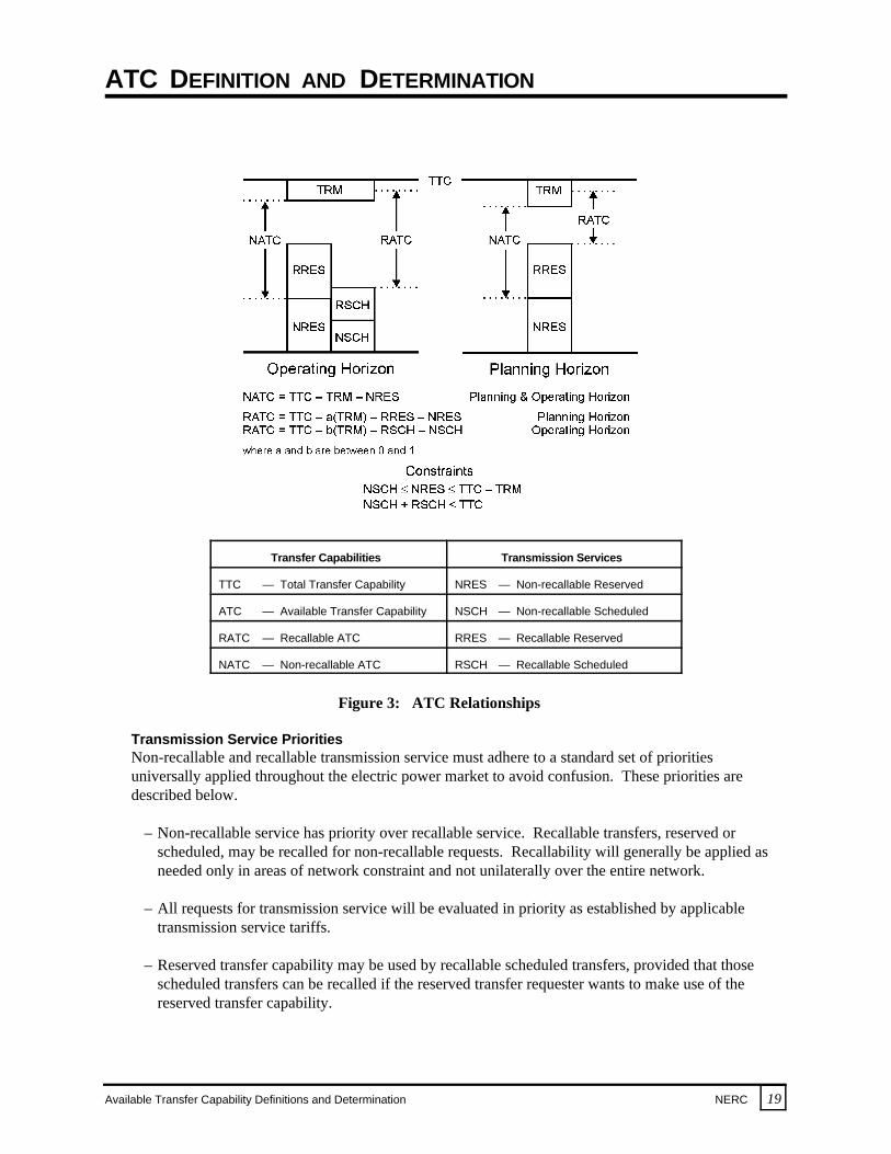
NATC and RATC are depicted graphically in Figure 2. TTC, ATC, and related terms in the trans-mission service reservation system are also shown in Figure 2. In general, the transition between theplanning and operating horizons will be a function of available information about the system, the statusof reserved and scheduled transmission services, and time considerations.
RECALLABLE AND NON-RECALLABLE RELATIONSHIPS AND PRIORITIES
The relationships and priorities of recallable and non-recallable concepts as they apply to both scheduledand reserved transmission services are described below. In addition, the interaction between recallable andnon-recallable transmission services and the effects on ATC values are discussed and illustrated.
Scheduled and Reserved Transmission ServiceReserved transmission service constitutes a reserved portion of the transmission network transfercapability, but the actual electric power transfer is not yet scheduled between areas. Scheduledtransmission service indicates that an electric power transfer will be occurring on the transmissionnetwork for the time period for which the transmission service was reserved. Both terms can apply toeither recallable or non-recallable transmission service, giving the following four transmission serviceterms:
– Non-recallable Reserved (NRES)
– Non-recallable Scheduled (NSCH)
– Recallable Reserved (RRES)
– Recallable Scheduled (RSCH)
The aggregate of the NSCH and RSCH must never exceed the TTC in the operational horizon. However, in the planning horizon, individual transmission providers may allow the aggregate of theNRES and RRES to exceed the TTC less TRM, to more fully utilize transmission assets, provided thatNRES by itself never exceeds TTC less TRM. Such over-subscription of recallable reservations mustbe disclosed to the purchasers of RRES. These ATC relationships are shown in Figure 3.
ATC DEFINITION AND DETERMINATION
Available Transfer Capability Definitions and Determination NERC 19
Transfer Capabilities Transmission Services
TTC — Total Transfer Capability NRES — Non-recallable Reserved
ATC — Available Transfer Capability NSCH — Non-recallable Scheduled
RATC — Recallable ATC RRES — Recallable Reserved
NATC — Non-recallable ATC RSCH — Recallable Scheduled
Figure 3: ATC Relationships
Transmission Service PrioritiesNon-recallable and recallable transmission service must adhere to a standard set of prioritiesuniversally applied throughout the electric power market to avoid confusion. These priorities aredescribed below.
– Non-recallable service has priority over recallable service. Recallable transfers, reserved orscheduled, may be recalled for non-recallable requests. Recallability will generally be applied asneeded only in areas of network constraint and not unilaterally over the entire network.
– All requests for transmission service will be evaluated in priority as established by applicabletransmission service tariffs.
– Reserved transfer capability may be used by recallable scheduled transfers, provided that thosescheduled transfers can be recalled if the reserved transfer requester wants to make use of thereserved transfer capability.
ATC DEFINITION AND DETERMINATION
20 NERC Available Transfer Capability Definitions and Determination
Several of the possible relationships of NATCs and RATCs to the different types of transfers that havebeen scheduled or reserved during a given time period are shown in Figure 4 and described below. These concepts apply to any time during the forecast period. Therefore, no time aspect is identified.
Transfer Capabilities Transmission Services
TTC — Total Transfer Capability NRES — Non-recallable Reserved
ATC — Available Transfer Capability NSCH — Non-recallable Scheduled
RATC — Recallable ATC RRES — Recallable Reserved
NATC — Non-recallable ATC RSCH — Recallable Scheduled
Figure 4: ATC Relationships and Priorities

ATC DEFINITION AND DETERMINATION
Available Transfer Capability Definitions and Determination NERC 21
– Non-recallable scheduled (NSCH) transfers are of the highest priority (all Examples). NSCHtransfers cannot be curtailed by the transmission provider except in cases where system reliabilityis threatened or an emergency exists. All NSCH transfers reduce the amount of ATC.
– Recallable ATC (RATC) can include transfer capability that is currently held by non-recallablereserved (NRES) transfers. However, the new transfers scheduled from the RATC may have to beinterrupted if the NRES transfer requester wants to make use of the transmission network(Example 1).
– Non-recallable ATC (NATC) cannot include transfer capability that is currently held by non-recallable reserved (NRES) transfers because the reserved transfer would have priority over anynew non-recallable transfer (Examples 1 and 3).
– Non-recallable ATC (NATC) can include transfer capability that is currently used by recallablescheduled (RSCH) transfers because a non-recallable transfer has priority over recallable transfers(Example 3).
– Recallable ATC (RATC) cannot include transfer capability that is currently used by recallablescheduled (RSCH) transfers because the scheduled transfer would have priority over any newtransfers (Examples 2 and 3).
– Both non-recallable ATC (NATC) and recallable ATC (RATC) can include recallable reserved(RRES) transfers (all Examples). However, any new recallable transfers may have to be inter-rupted if the RRES requester wants to make use of the transmission network (Examples 2 and 3).
The Examples in Figures 3 and 4 illustrate how ATC may be applied in the conduct of commercialbusiness. These definitions have no impact on the physical determination of how much additionaltransfers the network can support.
Appendix C further demonstrates the interaction between recallable and non-recallable transmissionservice and the effects on ATC values.
APPENDIX A. NETWORK RESPONSE METHOD FOR ATC DETERMINATION
22 NERC Available Transfer Capability Definitions and Determination
The example in this Appendix describes an ATC calculation approach that may be termed a “networkresponse” method. It demonstrates the ATC Principles described in this report and the physical impacts ofelectric power transfers on an interconnected transmission network. The method is intended to be illus-trative of a procedure that is applicable in highly dense, meshed transmission networks where customerdemand, generation sources, and the transmission systems are tightly interconnected. In such networks,transmission paths critical to a particular electric power transfer cannot generally be identified in advance. The critical path will be very much a function of the conditions that exist at the time the transfer isscheduled. The example does not introduce any concepts not covered in the front or main portion of thisreport.
PHYSICAL SYSTEM IMPACTS OF TRANSFERS
Determination of ATC requires some translation from the area to area transactions to the resultant electricpower flows on the transmission network. This translation is done by stressing the system with appropriatetransfers under critical contingencies to determine the characteristic response of the network. Thesenetwork response characteristics, which are based on the line outage, power transfer, and outage transferdistribution factors of NERC’s May 1995 NERC Transmission Transfer Capability reference document,can be determined by transfer capability studies either beforehand, or on a transaction-by-transaction basis.
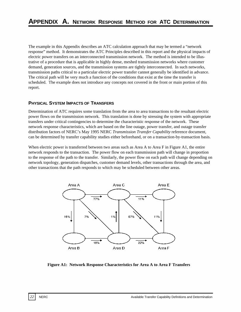
When electric power is transferred between two areas such as Area A to Area F in Figure A1, the entirenetwork responds to the transaction. The power flow on each transmission path will change in proportionto the response of the path to the transfer. Similarly, the power flow on each path will change depending onnetwork topology, generation dispatches, customer demand levels, other transactions through the area, andother transactions that the path responds to which may be scheduled between other areas.
Figure A1: Network Response Characteristics for Area A to Area F Transfers

APPENDIX A. NETWORK RESPONSE METHOD FOR ATC DETERMINATION
Available Transfer Capability Definitions and Determination NERC 23
To illustrate this, computer simulation studies are performed to determine the transfer capability from AreaA to Area F. During that process, it is determined that 77% of electric power transfers from Area A toArea F will flow on the transmission path between Area A and Area C (Figure A1).
Through application of those response characteristics, the impact on the path between Area A and Area Cfor a 500 MW transfer from Area A to Area F is graphically described in Figure A2. In this example, apre-existing 160 MW power flow exists from Area A to Area C due to a generation dispatch and thelocation of customer demand centers on the modeled network. When a 500 MW transfer is scheduled fromArea A to Area F, an additional 385 MW (77% of 500 MW) flows on the transmission path from Area Ato Area C, resulting in a 545 MW power flow from Area A to Area C.
Figure A2: Existing vs. Resultant Power Flowson Path A to C for a 500 MW Transfer from Area A to Area F
To determine the ability of the network to transfer electric power from Area A to Area F, additionalpotential impacts within the individual areas must also be recognized. The network responses shown inFigure A1 must be expanded to consider possible transmission limits within each area.
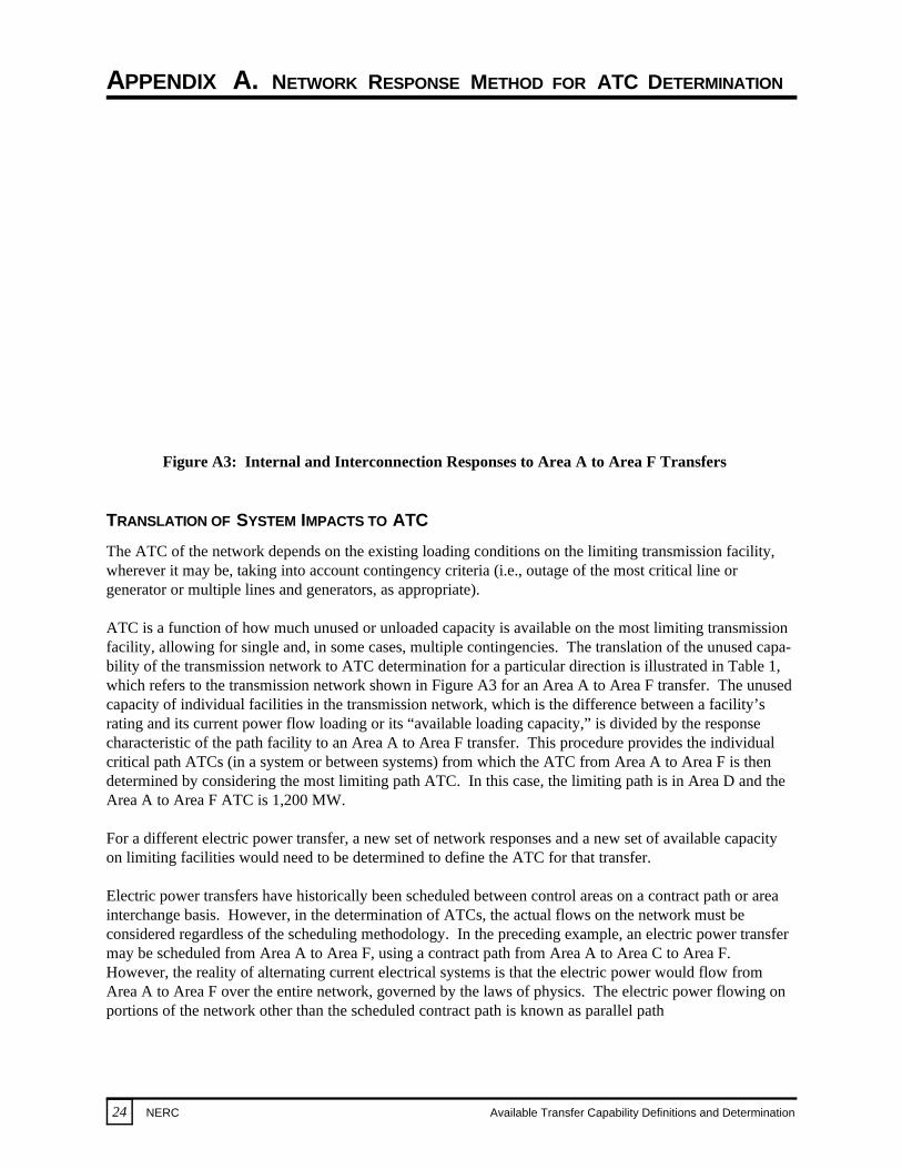
The response characteristics of limiting facilities within the individual areas for an Area A to Area Ftransfer are shown in Figure A3. For simplicity, the flows within each area are not shown. Rather, thefigures within each area represent the percentage of the transfer from Area A to Area F that flows on themost limiting facility within each area. Recognition of the limiting path responses within the individualareas for Area A to Area F transfers increases the complexity of determining the Area A to Area F ATC.
APPENDIX A. NETWORK RESPONSE METHOD FOR ATC DETERMINATION
24 NERC Available Transfer Capability Definitions and Determination
Figure A3: Internal and Interconnection Responses to Area A to Area F Transfers
TRANSLATION OF SYSTEM IMPACTS TO ATC
The ATC of the network depends on the existing loading conditions on the limiting transmission facility,wherever it may be, taking into account contingency criteria (i.e., outage of the most critical line orgenerator or multiple lines and generators, as appropriate).
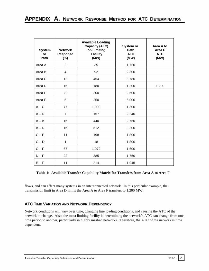
ATC is a function of how much unused or unloaded capacity is available on the most limiting transmissionfacility, allowing for single and, in some cases, multiple contingencies. The translation of the unused capa-bility of the transmission network to ATC determination for a particular direction is illustrated in Table 1,which refers to the transmission network shown in Figure A3 for an Area A to Area F transfer. The unusedcapacity of individual facilities in the transmission network, which is the difference between a facility’srating and its current power flow loading or its “available loading capacity,” is divided by the responsecharacteristic of the path facility to an Area A to Area F transfer. This procedure provides the individualcritical path ATCs (in a system or between systems) from which the ATC from Area A to Area F is thendetermined by considering the most limiting path ATC. In this case, the limiting path is in Area D and theArea A to Area F ATC is 1,200 MW.
For a different electric power transfer, a new set of network responses and a new set of available capacityon limiting facilities would need to be determined to define the ATC for that transfer.
Electric power transfers have historically been scheduled between control areas on a contract path or areainterchange basis. However, in the determination of ATCs, the actual flows on the network must beconsidered regardless of the scheduling methodology. In the preceding example, an electric power transfermay be scheduled from Area A to Area F, using a contract path from Area A to Area C to Area F. However, the reality of alternating current electrical systems is that the electric power would flow fromArea A to Area F over the entire network, governed by the laws of physics. The electric power flowing onportions of the network other than the scheduled contract path is known as parallel path
APPENDIX A. NETWORK RESPONSE METHOD FOR ATC DETERMINATION
Available Transfer Capability Definitions and Determination NERC 25
System Network on Limiting Path Area For Response Facility ATC ATC
Path (%) (MW) (MW) (MW)
Available Loading Capacity (ALC) System or Area A to
Area A 2 35 1,750
Area B 4 92 2,300
Area C 12 454 3,780
Area D 15 180 1,200 1,200
Area E 8 200 2,500
Area F 5 250 5,000
A – C 77 1,000 1,300
A – D 7 157 2,240
A – B 16 440 2,750
B – D 16 512 3,200
C – E 11 198 1,800
C – D 1 18 1,800
C – F 67 1,072 1,600
D – F 22 385 1,750
E – F 11 214 1,945
Table 1: Available Transfer Capability Matrix for Transfers from Area A to Area F
flows, and can affect many systems in an interconnected network. In this particular example, thetransmission limit in Area D limits the Area A to Area F transfers to 1,200 MW.
ATC TIME VARIATION AND NETWORK DEPENDENCY
Network conditions will vary over time, changing line loading conditions, and causing the ATC of thenetwork to change. Also, the most limiting facility in determining the network’s ATC can change from onetime period to another, particularly in highly meshed networks. Therefore, the ATC of the network is timedependent.

APPENDIX A. NETWORK RESPONSE METHOD FOR ATC DETERMINATION
26 NERC Available Transfer Capability Definitions and Determination
This characteristic is illustrated conceptually in Figure A4. The first group of graphs on the left-hand sideof the figure presents the available loading capacity at different points in time (T , T , T ) for several lines1 2 3
in an interconnected network. If an Area A to Area B transfer is to be scheduled at T , each of the lines1
(line 1 in Area A, line 3 in Area B, line 7 in Area B, and line 16 in Area D) will respond to the transfer inaccordance with its network response factor. This factor is used to determine an ATC as limited by eachindividual facility. The results are shown on the middle set of diagrams of Figure A4. The ATC for thenetwork as a whole represents the minimum of the ATCs as defined by each facility at each time frame. These minimum ATCs are schematically illustrated in the right side of Figure A4. As demonstrated, theATC is different for each time period and is determined by a different facility in each period.
Figure A4: ATC Variance
APPENDIX A. NETWORK RESPONSE METHOD FOR ATC DETERMINATION
Available Transfer Capability Definitions and Determination NERC 27
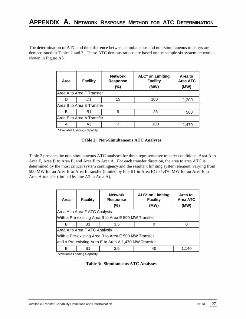
The determination of ATC and the difference between simultaneous and non-simultaneous transfers aredemonstrated in Tables 2 and 3. These ATC demonstrations are based on the sample six system networkshown in Figure A3.
Network ALC* on Limiting Area toArea Facility Response Facility Area ATC
(%) (MW) (MW)
Area A to Area F TransferD D1 15 180 1,200
Area B to Area E TransferB B1 5 25 500
Area E to Area A TransferA A2 7 103 1,470
*Available Loading Capacity
Table 2: Non-Simultaneous ATC Analyses
Table 2 presents the non-simultaneous ATC analyses for three representative transfer conditions: Area A toArea F, Area B to Area E, and Area E to Area A. For each transfer direction, the area to area ATC isdetermined by the most critical system contingency and the resultant limiting system element, varying from500 MW for an Area B to Area E transfer (limited by line B1 in Area B) to 1,470 MW for an Area E toArea A transfer (limited by line A2 in Area A).
Network ALC* on Limiting Area to Area Facility Response Facility Area ATC
(%) (MW) (MW)
Area A to Area F ATC AnalysisWith a Pre-existing Area B to Area E 500 MW Transfer
B B1 3.5 0 0Area A to Area F ATC AnalysisWith a Pre-existing Area B to Area E 500 MW Transfer and a Pre-existing Area E to Area A 1,470 MW Transfer
B B1 3.5 40 1,140*Available Loading Capacity
Table 3: Simultaneous ATC Analyses
APPENDIX A. NETWORK RESPONSE METHOD FOR ATC DETERMINATION
28 NERC Available Transfer Capability Definitions and Determination
The first section of Table 3 shows a determination of ATC for an Area A to Area F transfer, assuming thatan Area B to Area E 500 MW transfer schedule is already in effect. Under this condition, the Area A toArea F ATC is now reduced from 1,200 MW (Table 2) to zero. This change is due to the increased loadingon line B1 due to the previously scheduled 500 MW transfer from Area B to Area E, making it the limitingnetwork facility. Note that the Area A to Area F transfer limiting facility was line D1 in Area D in the non-simultaneous analysis (Table 2).
The second portion of Table 3 is another determination of ATC for an Area A to Area F transfer. In thisexample, pre-existing transfers are in place from Area B to Area E of 500 MW and Area E to Area A of1,470 MW. Under these conditions, the ATC for an Area A to Area F transfer is found to be 1,140 MW. This transfer is a slight reduction from the 1,200 MW ATC determination in the non-simultaneous case(Table 2), but is a significant increase from the zero ATC found in the previous case (first part of Table 3). This increased transfer is due to the offsetting effect of the flows caused by the pre-existing Area E to AreaA transfer, which reduced the line loading on the critical facility B1, thus increasing the ATC for the AreaA to Area F transfer direction.
These examples demonstrate that the determination of ATC in a tightly interconnected network is verymuch a function of system conditions that exist on the network at the time the transfer is to be scheduled. In addition, ATC is a function of the specifics of the electric power transfer being considered in terms of itsdirection, amount, and duration. To be able to properly appraise the performance of tightly interconnectednetworks to support contemplated transfers (i.e., what is the ATC), a regional or wide-area approach mustbe considered so that all network conditions are properly taken into account.

APPENDIX B. RATED SYSTEM PATH METHOD FOR ATC DETERMINATION
Available Transfer Capability Definitions and Determination NERC 29
OVERVIEW
The rated system path (RSP) method for ATC determination is typically used for transmission systems thatare characterized by sparse networks with customer demand and generation centers distant from oneanother. Generally in this approach, paths between areas of the network are identified and appropriatesystem constraints determined. ATC is computed for these identified paths and interconnections betweentransmission providers.
The RSP method involves three steps: 1) determining the path’s Total Transfer Capability (TTC),2) allocating the TTC among owners in a multi-owned path to determine the owners’ rights, and3) calculating ATC for each right-holder by subtracting each of their uses from each of their individualTTC rights. Wide-area coordination is achieved by developing the TTC in a manner that follows a regionalreview process. This process assures individual, power pool, subregional, and Regional coordination andthe necessary consideration of the interconnection network’s constraints and conditions.
The RSP method includes a procedure for allocating TTC, and in turn ATC, among the owners of the trans-mission path(s). It should be noted that the RSP method of allocation is not the only procedure that may befollowed in allocating transmission services.
UNSCHEDULED FLOW OR PARALLEL PATH FLOW
The RSP approach accounts for the effects of unscheduled flow (parallel path flow) on interconnectedsystems through the modeling of realistic customer demand and generation patterns in advance of real-timeoperations, and uses a maximum power flow test to ensure that the transfer path is capable of carryingpower flows up to its rated transfer capability or TTC.
The rating process begins by modeling the interconnected network with the actual flow that will occur onthe path and its parallel paths under realistically stressed conditions. The lines comprising the path may berated and operated as a single path. The network is tested under a wide range of generation, customerdemand, and facility outage conditions to determine a reliability-based TTC. When determined this way,the TTC rating usually remains fairly constant except for system configuration changes such as a lineoutage situation. To implement the RSP ATC method, consistent path rating methods and procedures mustbe agreed upon and followed within the Interconnection.
Non-simultaneous ratings are normally used as the basis for calculating ATC. If, however, two rated pathshave a simultaneous effect on each other, the rating process identifies the simultaneous capabilities orestablishes nomograms that govern the simultaneous operation of the paths. Applicable operatingprocedures are negotiated to ensure reliable network operation. Where simultaneous operation is necessary,operator control is used to ensure safe and reliable operation of the transmission network.

APPENDIX B. RATED SYSTEM PATH METHOD FOR ATC DETERMINATION
Available Transfer Capability Definitions and Determination NERC 31
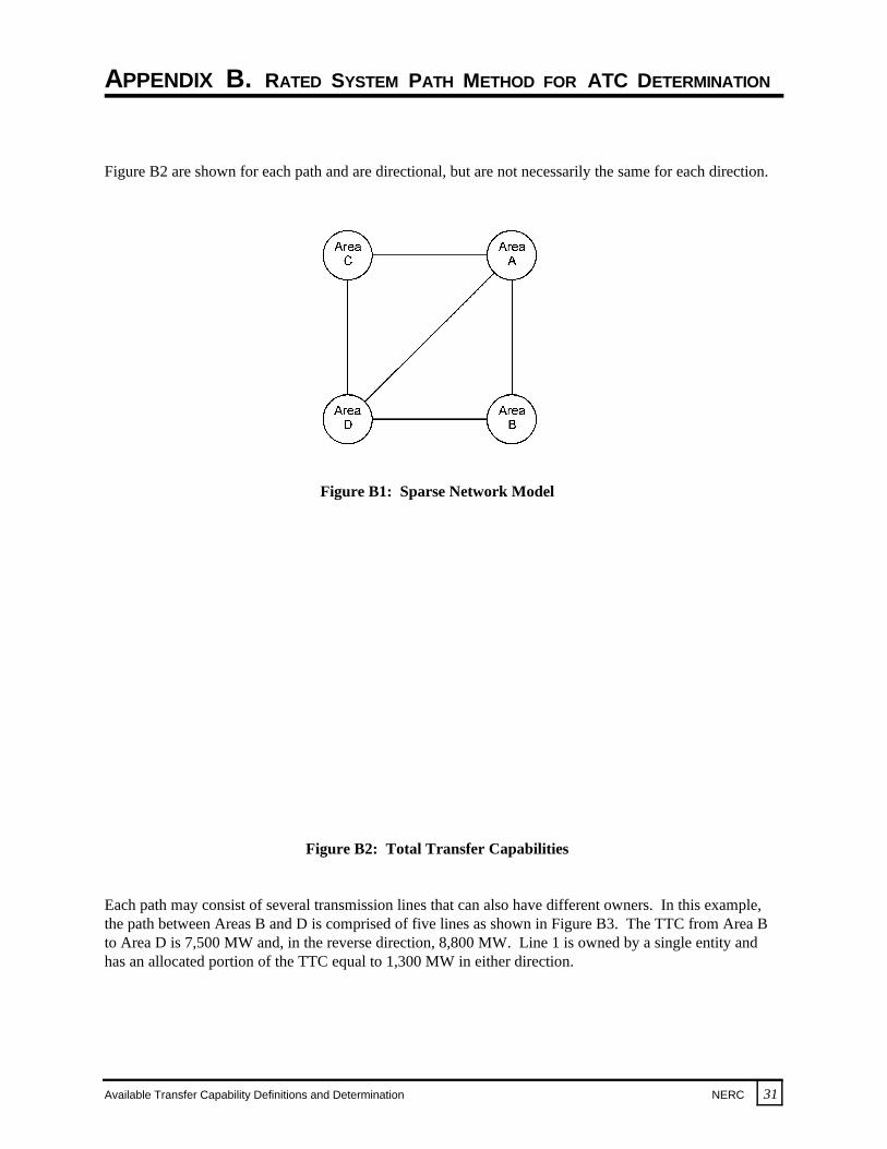
Figure B2 are shown for each path and are directional, but are not necessarily the same for each direction.
Figure B1: Sparse Network Model
Figure B2: Total Transfer Capabilities
Each path may consist of several transmission lines that can also have different owners. In this example,the path between Areas B and D is comprised of five lines as shown in Figure B3. The TTC from Area Bto Area D is 7,500 MW and, in the reverse direction, 8,800 MW. Line 1 is owned by a single entity andhas an allocated portion of the TTC equal to 1,300 MW in either direction.

APPENDIX B. RATED SYSTEM PATH METHOD FOR ATC DETERMINATION
32 NERC Available Transfer Capability Definitions and Determination
Figure B3: TTCs of Path B to D and Allocation of TTCs to Line 1
This example reflects a snapshot in time during the planning horizon. Initial transmission servicereservations, all assumed to be non-recallable, are shown for each path in Figure B4. The correspondingATC for each path has been calculated by subtracting the non-recallable service from the TTC. Because allthe transmission service reservations are assumed on each path to be in one direction, the path ATC is onlycalculated for that direction.
Figure B4: Initial Transmission Service Reservations

APPENDIX B. RATED SYSTEM PATH METHOD FOR ATC DETERMINATION
Available Transfer Capability Definitions and Determination NERC 33
For example, referring to Figure B4, the ATC from Area B to Area D is calculated as 7,500 MW less 4,000MW or 3,500 MW. For line 1 of the B to D path, the ATC is 1,300 MW less 200 MW or 1,100 MW. Inthe next case, as shown in Figure B5, 1,000 MW of non-recallable transmission service is acquired fromArea A to Area B to Area D. No other changes occur. The total transmission service reserved from Area Ato Area B is 1,500 MW, and the resulting ATC goes to zero. The ATC from Area B to Area D reduces to2,500 MW (7,500 MW TTC less 5,000 MW reserved transmission service). It is assumed the 1,000 MWof the new reserved transmission service was obtained from the owner of line 1, resulting in the totalreserved transmission service on this line being 1,200 MW. The new ATC for line 1 is 100 MW (1,300MW TTC less 1,200 MW reserved transmission service).
Figure B5: New Transmission Service Reservation on Path A to B to D
The non-recallable transmission service reserved for a path in each direction may not exceed the path’stransfer capability in either direction under any circumstances. These limits are consistent with NERCOperating Policies.
Unscheduled flow may at times preclude scheduling to a path’s full transfer capability or TTC. If aninternal limit is encountered in any system as a result of the transaction from Area A to Area D, forexample in Area D, Area D’s system operator must respond to relieve the limitation such as by redis-patching generation or using phase shifter control. An unscheduled flow mitigation plan might also beimplemented to relieve excessive unscheduled flow problems. Additional relief may be achieved bycurtailing schedules that are contributing to the unscheduled flow on the path or by increasing schedulesthat would create unscheduled flow in the opposite direction. In this example, if path A to D were limiting,unscheduled flow mitigation procedures could be implemented to initiate coordinated operation ofcontrollable devices such as phase-shifting transformers to relieve the limitation.
APPENDIX B. RATED SYSTEM PATH METHOD FOR ATC DETERMINATION
34 NERC Available Transfer Capability Definitions and Determination
There will probably be times in the operating horizon when the use of the transmission network results inactual flows on a transmission path being less than the transmission scheduled on the path. During theseperiods, if the transmission path is fully scheduled, additional electric power may be scheduled to Area Dfrom Area A by reserving transmission service over a different transmission path. In this case, trans-mission service could be obtained from either the owners of the direct path between Area A and Area D orthe owners of the transmission system from Area A to Area C to Area D.
For the RSP method, the transmission rights to be reserved and scheduled by all transmission users areconsistent with the rating of the transmission paths. If determined through a coordinated process usingmodels that capture the major effects of the interconnected network, these ratings will create limits thatresult in the reliable operation of the regional electric system. The owners of the transmission paths,through a negotiated allocation process, will know their transmission service rights and the resulting use ofthese rights will be consistent with the physical capability and limitations of the transmission network. This RSP method assures efficient use and reliable operation of the interconnected transmission network.
APPENDIX C. TRANSMISSION SERVICE RESERVATIONS AND SCHEDULING
Available Transfer Capability Definitions and Determination NERC 35
OVERVIEW
The following scenarios demonstrate how the 1,200 MW ATC quantity from Area A to Area F in theexample in Appendix A may be commercially employed. The interplay between recallable and non-recallable transmission service and the resulting effects upon calculated ATCs are demonstrated using theequations presented in the “ATC Definition and Determination” section of this report. They clearlydemonstrate that, although both recallable and non-recallable ATC are offered simultaneously, thecombined total of recallable and non-recallable service does not exceed the TTC at any time.
For the purpose of this illustration, assume that conditions on the interconnected network are as describedin Tables 1 and 2 of Appendix A. Under this scenario, the network ATC from Area A to Area F for thistime period in the operating horizon is 1,200 MW. Also, for simplicity, assume that previous transmissioncommitments are zero. Thus, TTC in the following cases is 1,200 MW. Lastly, assume that TRM is zero. The resulting relevant simplified ATC equations for the operating horizon are:
NATC = TTC – NRES
RATC = TTC – RSCH – NSCH
The equations that describe the TTC constraints during this time frame are:
NRES < TTC
RSCH + NSCH < TTC
ATC DEMONSTRATION — SCENARIO 1
Consider the initial case identified in Figure C1 as Case 1. Reservations for 200 MW of recallable and 400MW of non-recallable transmission service have been reserved against the 1,200 MW TTC.
Case 1 includes schedules for only 300 MW of non-recallable transmission service. Thus:
NATC = TTC – NRES = 1,200 – 400
= 800 MW
RATC = TTC – RSCH – NSCH = 1,200 – 0 – 300
= 900 MW
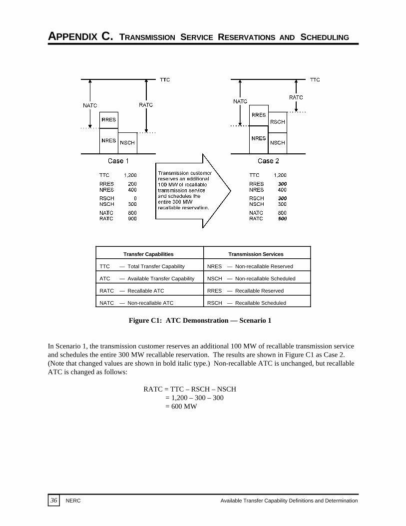
APPENDIX C. TRANSMISSION SERVICE RESERVATIONS AND SCHEDULING
36 NERC Available Transfer Capability Definitions and Determination
Transfer Capabilities Transmission Services
TTC — Total Transfer Capability NRES — Non-recallable Reserved
ATC — Available Transfer Capability NSCH — Non-recallable Scheduled
RATC — Recallable ATC RRES — Recallable Reserved
NATC — Non-recallable ATC RSCH — Recallable Scheduled
Figure C1: ATC Demonstration — Scenario 1
In Scenario 1, the transmission customer reserves an additional 100 MW of recallable transmission serviceand schedules the entire 300 MW recallable reservation. The results are shown in Figure C1 as Case 2. (Note that changed values are shown in bold italic type.) Non-recallable ATC is unchanged, but recallableATC is changed as follows:
RATC = TTC – RSCH – NSCH = 1,200 – 300 – 300
= 600 MW
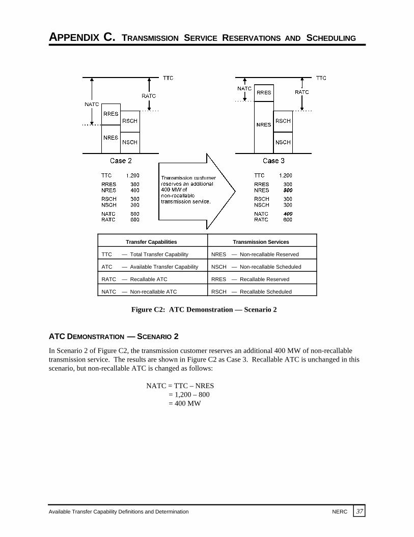
APPENDIX C. TRANSMISSION SERVICE RESERVATIONS AND SCHEDULING
Available Transfer Capability Definitions and Determination NERC 37
Transfer Capabilities Transmission Services
TTC — Total Transfer Capability NRES — Non-recallable Reserved
ATC — Available Transfer Capability NSCH — Non-recallable Scheduled
RATC — Recallable ATC RRES — Recallable Reserved
NATC — Non-recallable ATC RSCH — Recallable Scheduled
Figure C2: ATC Demonstration — Scenario 2
ATC DEMONSTRATION — SCENARIO 2
In Scenario 2 of Figure C2, the transmission customer reserves an additional 400 MW of non-recallabletransmission service. The results are shown in Figure C2 as Case 3. Recallable ATC is unchanged in thisscenario, but non-recallable ATC is changed as follows:
NATC = TTC – NRES = 1,200 – 800 = 400 MW
APPENDIX C. TRANSMISSION SERVICE RESERVATIONS AND SCHEDULING
38 NERC Available Transfer Capability Definitions and Determination
Transfer Capabilities Transmission Services
TTC — Total Transfer Capability NRES — Non-recallable Reserved
ATC — Available Transfer Capability NSCH — Non-recallable Scheduled
RATC — Recallable ATC RRES — Recallable Reserved
NATC — Non-recallable ATC RSCH — Recallable Scheduled
Figure C3: ATC Demonstration — Scenario 3
ATC DEMONSTRATION — SCENARIO 3
In Scenario 3 of Figure C3, the transmission customer reserves and schedules an additional 300 MW ofnon-recallable transmission service. The results are shown in Figure C3 as Case 4. In this scenario, bothrecallable and non-recallable ATCs are changed as follows:
NATC = TTC – NRES RATC = TTC – RSCH – NSCH = 1,200 – 1,100 = 1,200 – 300 – 600 = 100 MW = 300 MW
Transmission customers holding the 200 MW of recallable transmission service reservations “above theTTC line” should be advised that they have a high probability of having their transmission service recalled.

APPENDIX C. TRANSMISSION SERVICE RESERVATIONS AND SCHEDULING
Available Transfer Capability Definitions and Determination NERC 39
Transfer Capabilities Transmission Services
TTC — Total Transfer Capability NRES — Non-recallable Reserved
ATC — Available Transfer Capability NSCH — Non-recallable Scheduled
RATC — Recallable ATC RRES — Recallable Reserved
NATC — Non-recallable ATC RSCH — Recallable Scheduled
Figure C4: ATC Demonstration — Scenario 4
ATC DEMONSTRATION — SCENARIO 4
In Scenario 4 of Figure C4, the transmission customer schedules an additional 400 MW of non-recallabletransmission service. The results are shown in Figure C4 as Case 5. Non-recallable ATC remainsunchanged at 100 MW. Unless 100 MW of recallable transmission service schedules are recalled, the totalschedules violate the TTC constraint. The transmission provider must recall 100 MW of scheduledrecallable transmission service. The recallable ATC calculation is then:
RATC = TTC – RSCH – NSCH = 1,200 – 200 – 1,000
= 0 MW
As this demonstration has shown, recallable transmission services may be reduced as non-recallable trans-mission services are reserved and scheduled, approaching the TTC limit.
TRANSMISSION TRANSFER CAPABILITY TASK FORCE
40 NERC Available Transfer Capability Definitions and Determination
Raymond M. Maliszewski (Chairman) Nicholas A. Brown (SPP)Senior Vice President–System Planning Director, Engineering & OperationsAmerican Electric Power Service Corporation Southwest Power PoolColumbus, Ohio Little Rock, Arkansas
Garey C. Rozier (Vice Chairman) Harlow R. Peterson (WSCC)Director of Bulk Power Supply Consultant Planning AnalystSouthern Company Services, Inc. Salt River ProjectAtlanta, Georgia Phoenix, Arizona
Robert W. Cummings (ECAR) John L. Griffin (WSCC)Manager, Transmission Services Senior Engineer/Policy AnalystEast Central Area Reliability Coordination Grid Customer Services Agreement Pacific Gas and Electric CompanyCanton, Ohio San Francisco, California
Lee E. Westbrook (ERCOT) William C. Phillips (Operating CommitteeTransmission Grid Planning ManagerTU Electric Director, Power System OperationsDallas, Texas Entergy Services, Inc.
Bruce M. Balmat (MAAC)Manager, System Services & Performance PJM Interconnection AssociationNorristown, Pennsylvania System Operations Analyst III
T.J. (Jim) Barker (MAIN)Manager–Electric System Engineering DepartmentCentral Illinois Public Service CompanySpringfield, Illinois
Terry L. Bundy (MAPP, Municipal, and Transmission Dependent Utility)Manager, Power Supply DivisionLincoln Electric SystemLincoln, Nebraska Vice President, Transmission and Engineering
Edward A. Schwerdt (NPCC and Canada)Director of EngineeringNortheast Power Coordinating Council New York, New York Vice President & General Manager
W.T. (Terry) Boston (SERC and Federal)Division Manager, Electric System ReliabilityTennessee Valley AuthorityChattanooga, Tennessee Director–Engineering
Liaison)
Pine Bluff, Arkansas
Robert Wayne Mitchell (Operating Committee Liaison Alternate)
Entergy Services, Inc.Pine Bluff, Arkansas
C.M. (Marty) Mennes (NERC Electronic Information Network Task Force)Director Power Supply Florida Power & Light CompanyMiami, Florida
Paul F. Barber (Power Marketer)
Citizens Lehman Power L.P.Boston, Massachusetts
Trudy Utter (Independent Power Producer)
Tenaska Power Services CompanyArlington, Texas
Virginia C. Sulzberger (NERC Staff)
North American Electric Reliability CouncilPrinceton, New Jersey