available transfer capability implementation document (mod … business/atcmethodology... ·...
TRANSCRIPT

Available Transfer Capability Implementation Document
(MOD-001-1a)
Bonneville Power Administration Transmission Services
Effective Date: April 1, 2018
ATC Implementation Document – Version 46 - i -
TABLE OF CONTENTS I. Purpose…………… ........................................................................................ 1 II. Definitions ............................................................................................... 1 III. Overview ................................................................................................ 2
Methodologies Selected ......................................................................... 2 MOD-029-1a ................................................................................ 2 MOD-008-1 ................................................................................. 2
Methodologies Not Applicable to BPA ......................................................... 2 ATC Calculations .................................................................................. 2
ATC Calculation Periods ................................................................. 2 Frequency of ATC Recalculation ........................................................ 2 Limiting Assumptions ..................................................................... 3
IV. Allocation Processes .................................................................................. 4 V. Outages ………………………………………………………………………………………………………………………………..4
Outage Planning ................................................................................... 4 VI. Priorities Used to Set TTC ........................................................................... 5 VII. Rated System Path Methodology ................................................................... 7
BPA Paths .......................................................................................... 7 Data and Assumptions .................................................................... 9
Process to Determine TTC ..................................................................... 11 Calculating Firm Transmission Service ...................................................... 13
Calculating Firm Existing Transmission Commitments (ETCF) ..................... 13 Calculating Firm Available Transfer Capability (ATCF) ............................. 15
Calculating Non-Firm Transmission Service ................................................ 17 Calculating Non-Firm Existing Transmission Commitments (ETCNF) .............. 18 Calculating Non-Firm Available Transfer Capability (ATCNF) ...................... 19 CounterflowNF are adjustments to ATCNF. ............................................ 24
VIII. Network Path Methodology ....................................................................... 25 BPA Network Paths .............................................................................. 25 Establishing Total Transfer Capability (TTC) ............................................... 28 Determining Existing Transmission Commitments (ETC) ................................. 28
Use of WECC Base Cases to Determine ETC .......................................... 28 Outages in ETC Calculations ............................................................ 29 Outage Criteria in ETC Calculations ................................................... 30 PTDF Analysis and De Minimis ......................................................... 30 Source/POR and Sink/POD Identification and Mapping ............................ 31
Calculating Firm Transmission Service ...................................................... 32 Calculating Firm Existing Transmission Commitments (ETCFi) ..................... 32 Determining Base ETCFi ................................................................. 34 Sensitivity Studies ....................................................................... 37 Determining Interim ETCFi Using PTDF Analysis ..................................... 39

ATC Implementation Document – Version 46 - ii -
Calculating Firm Available Transfer Capability (ATCF) ............................. 39 Calculating Non-Firm Transmission Service ................................................ 42
Calculating Non-Firm Existing Transmission Commitments (ETCNFi) .............. 42 Calculating Non-Firm Available Transfer Capability (ATCNF) ...................... 44
IX. Data Sources and Recipients ...................................................................... 49 X. Responding to Data Requests ...................................................................... 50 XI. ATCID Revisions ...................................................................................... 51 XII. Version History ....................................................................................... 51
ATC Implementation Document – Version 46 Page 1
I. Purpose 3
This BPA Available Transfer Capability Implementation Document (ATCID) addresses all of the 4 requirements of North American Electric Reliability Corporation (NERC) Reliability Standard 5 MOD-001-1a Available Transmission System Capability. This ATCID is specifically required by 6 MOD-001-1a, R3 and its subrequirements. This ATCID only applies to ATC calculations through 7 month 13. 8
II. Definitions 9
All capitalized terms used in this ATCID are either contained in NERC’s Glossary of Terms used 10 in NERC Reliability Standards or, if not in NERC’s glossary, are defined in this ATCID. 11
Defined terms specific to BPA include: 12
• Federal Columbia River Power System (FCRPS): The Transmission System 13 constructed and operated by BPA and the 31 federally-constructed hydroelectric 14 dams1 on the Columbia and Snake Rivers, and the Columbia Generating Station nuclear 15 plant. Each entity is separately managed and financed, but the facilities are operated 16 as an integrated power System. 17
• Federal Columbia River Transmission System (FCRTS): The FCRTS is comprised of 18 BPA’s main grid network Facilities (Network), Interconnections with other 19 Transmission Systems (External Interconnections2), Interties,3 delivery Facilities, 20 subgrid Facilities, and generation Interconnection Facilities within the Pacific 21 Northwest region and with western Canada and California. 22
• Long-Term Reservation: a confirmed reservation that has duration greater than or 23 equal to 365 days or any confirmed firm Network Integration Transmission Service 24 reservation. 25
• Short-Term Reservation: a confirmed reservation that has duration less than 365 26 days, excluding confirmed firm Network Integration Transmission Service reservations. 27
1 Albeni Falls, Anderson Ranch, Big Cliff, Black Canyon, Boise River Diversion, Bonneville, Chandler, Chief Joseph, Cougar, Detroit, Dexter, Dworshak, Foster, Grand Coulee, Green Peter, Green Springs, Hills Creek, Hungry Horse, Ice Harbor, John Day, Libby, Little Goose, Lookout Point, Lost Creek, Lower Granite, Lower Monumental, McNary, Minidoka, Palisades, Roza and The Dalles
2 Northern Intertie, Reno-Alturas Transmission System, West of Hatwai, West of Garrison and LaGrande paths.
3 California-Oregon AC Intertie, Pacific DC Intertie, and Montana Intertie.
ATC Implementation Document – Version 46 Page 2
III. Overview 28
BPA owns and provides Transmission Service over the FCRTS (see p. 3 for definition). BPA is 29 registered with NERC as a Transmission Operator (TOP) and Transmission Service Provider 30 (TSP), among other registrations. 31
Methodologies Selected 32
MOD-029-1a 33
BPA has elected to use the Rated System Path Methodology (MOD-029-1a) to calculate ATC 34 for its ATC Paths. The description of how BPA implements this methodology for these 35 paths is included in Sections VII, VIII, and IX of this ATCID. (MOD-001 R1) 36
MOD-008-1 37
BPA maintains Transmission Reliability Margin (TRM) as described in NERC Standard MOD-38 008-1 for its Northern Intertie Path. The description of how BPA implements TRM can be 39 found in BPA’s TRM Implementation Document (TRMID) found on BPA’s website 40 http://transmission.bpa.gov/business/atc_methodology/. BPA does not maintain TRM for 41 any other ATC Path. 42
Methodologies Not Applicable to BPA 43
BPA does not use the Area Interchange Methodology (MOD-028-2), the Flowgate 44 Methodology (MOD-030-2), or a Capacity Benefit Margin (CBM) (MOD-004-1). Therefore 45 these standards are not applicable to BPA. 46
ATC Calculations 47
ATC Calculation Periods 48
BPA calculates ATC values using the Rated System Path Methodology for the following time 49 periods: (MOD-001 R2) 50
• Hourly values for up to 168 hours. The next hour may be calculated in subhourly 51 intervals, with the most limiting subhourly ATC value being the hourly value. (MOD-001 52 R2.1) 53
• Daily values for day 3 through day 90. For days 3 to 7 (up to hour 168), the daily ATC 54 value is the most limiting hourly ATC value for that day. (MOD-001 R2.2) 55
• Monthly values for month 2 through month 13. For months 2 and 3 (up to day 90), the 56 monthly ATC value is the most limiting daily ATC value for that month. (MOD-001 R2.3) 57
Frequency of ATC Recalculation 58
BPA recalculates ATC on the following frequency, even if the calculated values 59 identified in the ATC equation are unchanged: (MOD-001 R8) 60
• Hourly, at least once per hour. (MOD-001 R 8.1) 61 • Daily, at least once per day. (MOD-001 R8.2) 62
ATC Implementation Document – Version 46 Page 3
• Monthly, at least once per day. (MOD-001 R8.3) 63
BPA may recalculate ATC values more frequently due to changes in Total Transfer 64 Capability (TTC), Power Transfer Distribution Factors (PTDFs), system issues or as deemed 65 necessary. 66
Limiting Assumptions 67
BPA operates the Bulk Electric System within equipment and electric System thermal, 68 voltage, and Stability Limits so that instability, uncontrolled separation, or cascading 69 failures of the System will not occur as a result of a sudden disturbance or unanticipated 70 failure of the System elements. BPA has some paths that are only thermally limited and 71 some paths that move between being thermally limited and stability limited depending on 72 the outage or System conditions. For those paths that move between being stability 73 limited4 and thermally limited, the System conditions for such paths determine the type 74 of limitation and which section of this document applies for the duration of the System 75 conditions. 76
Stability Limited Paths 77
BPA studies assumptions of various System conditions to develop the System Operating 78 Limits (SOLs) for its planning of operations. Paths are stability limited when the Stability 79 Limit is lower than the thermal limit. When this is the case BPA uses the SOL as the TTC in 80 its ATC calculations. Therefore when determining the TTC, BPA uses studied assumptions 81 that are no more limiting than those used to determine the SOLs in its planning of 82 operations for the corresponding time period, when such planning of operations has been 83 performed for that time period. (MOD-001 R6) 84
When calculating ATC, BPA subtracts its Existing Transmission Commitments (ETC) from 85 the TTC determined from the studied assumptions that BPA uses to develop SOLs for its 86 planning of operations. No additional studies beyond those developed to determine SOLs 87 and used in calculating TTCs are performed to calculate ATC. BPA may use more recent 88 System condition information in its SOL calculations when the studies are updated after 89 the ETC Cases are performed. However, this is not considered a difference in 90 assumptions. Therefore, there are no different assumptions used to calculate ATC to 91 compare to assumptions used in BPA’s planning of operations. (MOD-001 R7) 92
4 Stability limited paths may include COI; North of John Day; North of Hanford, N-S; West of Garrison; Northern Intertie; West of Cascades North; West of Cascades South.
ATC Implementation Document – Version 46 Page 4
Thermally Limited Paths 93
BPA studies assumptions of various system conditions to develop TTCs for thermally 94 limited paths. When determining the path TTC, BPA studies assumptions that are no more 95 limiting than those used in its planning of operations studies for the corresponding time 96 period, when such planning of operations has been performed for that time period. (MOD-97 001 R6) 98
BPA may use more recent system condition information in its TTC calculations when the 99 studies are updated after the ETC Cases are performed. However, this is not considered a 100 difference in assumptions. Therefore, there are no different assumptions used to 101 calculate ATC to compare to assumptions used in BPA’s planning of operations. (MOD-001 102 R7) 103
IV. Allocation Processes 104
BPA uses the same methodology to allocate transfer capability among multiple lines or sub-105 paths within a larger ATC Path as it uses to allocate transfer capability among multiple 106 owners or users of an ATC Path. For Paths where ownership Agreements exists, the 107 methodology is to allocate transfer capabilities according to contractual rights defined in 108 individual Agreements among the various owners. These Agreements define the specific 109 percentages of capacity or MW amounts of rights assigned to each owner for specific time 110 periods. Agreements do not exist for three of BPA’s Network Paths: South of Allston S>N, 111 Columbia Injection N>S and Wanapum Injection N>S. For South of Allston S>N the same 112 allocation methodology described in the SOA N>S Contract (#06TX-12300) is used. For 113 Columbia Injection N>S and Wanapum Injection N>S, BPA determines its share of Total 114 Transfer Capability based on BPA’s owned transmission lines that make up the Network Path 115 when all lines are in service. During outage conditions, individual allocations exist for the 116 loss of each transmission line in the Network Path. BPA determines its share of Existing 117 Transmission Commitments for Columbia Injection N>S and Wanapum Injection N>S by 118 modeling the full path of BPA’s lines only. 119
At this time BPA does not allocate transfer capabilities between TSPs to address forward-120 looking congestion management and seams coordination. (MOD-001 R3.5) 121
V. Outages 122
Outages from all TSPs that are internal or adjacent to BPA’s Balancing Authority Area (BAA) 123 can be mapped to the WECC base cases. (MOD-001 R3.6.3) 124
Outage Planning 125
Outage plans and the policy are posted to the Outage Plans website at: 126 http://www.bpa.gov/transmission/Reports/Pages/Proposed-Outages.aspx. 127
Outage Criteria for TTC Calculations 128
ATC Implementation Document – Version 46 Page 5
BPA incorporates outages into the TTC calculations after they have been studied by BPA or 129 provided to BPA by another TOP. Generally, BPA studies outages 10 to 16 days prior to the 130 outage start date. 131
The duration of an outage is not a criteria by which BPA determines which outages to 132 incorporate in its daily and monthly TTC calculations. The most conservative hourly TTC 133 calculated for a given outage or combination of outages becomes the governing TTC for the 134 daily calculation period. Likewise, the most conservative daily TTC for a given outage or 135 combination of outages becomes the governing TTC for the monthly calculation period. 136 (MOD-001 R3.6.1) (MOD-001 R.3.6.2) 137
VI. Priorities Used to Set TTC 138
Stability Limited Paths 139
BPA may update assumptions and calculate new SOLs when changes to System conditions will 140 significantly impact those limits and may use those updated assumptions to determine new 141 TTC values for stability limited paths. The following hierarchy of priorities categorizes the 142 SOL values based on the time period being calculated and the reason for the change. This 143 prioritization may then be used to revise the path TTC for a given time period if BPA 144 determines that more recent assumptions to calculate SOL values better reflect updated 145 System information: 146
• Real-time limit (highest priority): The “Real-time limit” priority governs when BPA 147 updates the assumptions of system conditions to calculate SOLs during the Real-time 148 horizon. A change to the SOL calculation with the Real-time priority governs all other 149 priorities. For example, if BPA receives an update that a scheduled outage will be 150 extended by two hours early in the Real-time day, BPA will update the assumptions for 151 the SOL calculation accordingly for the additional two hours and may use those same 152 updated assumptions to update the TTC. If there are multiple real-time updates to 153 assumptions for SOL calculations, the most recent SOL calculated governs. 154
• Scheduling limit: The “scheduling limit” priority may be used occasionally when the 155 assumptions for the SOL are not governing or an actual scheduling limit has been 156 imposed. If there is more than one scheduling limit, the lowest scheduling limit 157 governs until a Real-time limit SOL is submitted. 158
• Pre-schedule forecast: The “pre-schedule forecast” SOL priority may be used for a 159 Path if the assumptions for the SOL calculations are updated for the pre-schedule 160 period. For example, for SOLs calculated for Network Paths that are derived using 161 nomograms, if the assumptions are re-evaluated just prior to the pre-schedule day to 162 incorporate updated data inputs, the TTC may be updated. The pre-schedule forecast 163 TTC governs over the ‘studied’ priority. 164
• Studied: The “studied” priority is used when there are outages where a study report 165 has been issued, including those provided by other TOPs. For example, if a study 166 report is issued evaluating assumptions for line outage system conditions, the SOLs in 167 that report govern over any lower-priority SOLs for the duration of the line outage 168 conditions. 169
• Estimated known limit: The “estimated known limit” priority is used to establish 170 unstudied TTCs or to define seasonal Path TTCs that govern over “short-term 171 seasonal” or “Path Rating” priorities. 172
ATC Implementation Document – Version 46 Page 6
• Short-term seasonal: The “short-term seasonal” priority is used for TTCs issued for 173 seasonal Path Ratings. As these Ratings may be higher at certain times during the 174 year, the short-term seasonal priority governs over the Path Rating priority. For 175 example, if the longer-term Path Rating for a path is 7800 MW, but seasonally this 176 Rating increases to 8000 MW, the short-term seasonal Rating of 8000 MW governs and 177 is used to set the TTC during the season to which it applies. 178
• Path Rating: The “Path Rating” priority is used to set base TTCs using either the 179 Rating of the Paths, SOLs studied using normal conditions, SOLs calculated for the 180 planning horizon, or all of the above. The lowest value resulting from the above 181 calculations governs for the given time period and is used to set the TTC. For 182 example, if under normal conditions the SOL for a path is 4410 MW, but the SOL 183 calculated for the planning horizon is 4100 MW, the lower SOL of 4100 MW governs and 184 is used to set the TTC for this Network Path. 185
• Informational limit (lowest priority): The “informational limit” is used while 186 establishing the initial setup of Paths within the scheduling and reservation system. 187 The informational limit is equal to the initial Path Rating of the Path. 188
Thermally Limited Paths 189
BPA may update assumptions and calculate new TTCs when changes to System conditions will 190 significantly impact those limits and may use those updated assumptions to determine new 191 TTC values for thermally limited paths. The following hierarchy of priorities categorizes the 192 TTC values based on the time period being calculated and the reason for the change. This 193 prioritization may then be used to revise the path TTC for a given time period if BPA 194 determines that more recent assumptions to calculate TTC values better reflect updated 195 System information: 196
• Real-time limit (highest priority): The “Real-time limit” priority governs when BPA 197 updates the assumptions of system conditions to calculate TTCs during the Real-time 198 horizon. A change to the TTC calculation with the Real-time priority governs all other 199 priorities. For example, if BPA receives an update that a scheduled outage will be 200 extended by two hours early in the Real-time day, BPA may update the TTC. 201
• Scheduling limit: The “scheduling limit” priority may be used occasionally when the 202 assumptions for the TTC are not governing or an actual scheduling limit has been 203 imposed. If there is more than one scheduling limit, the lowest scheduling limit 204 governs until a Real-time limit TTC is submitted. 205
• Pre-schedule forecast: The “pre-schedule forecast” TTC priority may be used for a 206 Path if the assumptions for the TTC calculations are updated for the pre-schedule 207 period. For example, for TTCs calculated for Network Paths that are derived using 208 nomograms, if the assumptions are re-evaluated just prior to the pre-schedule day to 209 incorporate updated data inputs, the TTC may be updated. The pre-schedule forecast 210 TTC governs over the ‘studied’ priority. 211
• Studied: The “studied” priority is used when there are outages where a study report 212 has been issued, including those provided by other TOPs. For example, if a study 213 report is issued evaluating assumptions for line outage system conditions, the TTCs in 214 that report govern over any lower-priority TTCs for the duration of the line outage 215 conditions. 216

ATC Implementation Document – Version 46 Page 7
• Estimated known limit: The “estimated known limit” priority is used to establish 217 unstudied TTCs or to define seasonal Path TTCs that govern over “short-term 218 seasonal” or “Path Rating” priorities. 219
• Short-term seasonal: The “short-term seasonal” priority is used for TTCs issued for 220 seasonal Path Ratings. As these Ratings may be higher at certain times during the 221 year, the short-term seasonal priority governs over the Path Rating priority. For 222 example, if the longer-term Path Rating for a path is 7800 MW, but seasonally this 223 Rating increases to 8000 MW, the short-term seasonal Rating of 8000 MW governs and 224 is used to set the TTC during the season to which it applies. 225
• Path Rating: The “Path Rating” priority is used to set base TTCs using either the 226 Rating of the Paths, TTCs studied using normal conditions, TTCs calculated for the 227 planning horizon, or all of the above. The lowest value resulting from the above 228 calculations governs for the given time period and is used to set the TTC. For 229 example, if under normal conditions the TTC for a Path is 4410 MW, but the TTC 230 calculated for the planning horizon is 4100 MW, the lower TTC of 4100 MW governs and 231 is used to set the TTC for this Network Path. 232
• Informational limit (lowest priority): The “informational limit” is used while 233 establishing the initial setup of Paths within the scheduling and reservation system. 234 The informational limit is equal to the initial Path Rating of the Path. 235
VII. Rated System Path Methodology 236
This section describes in detail how BPA implements the Rated System Path methodology for 237 the Paths listed in Table 1. It addresses all of the Requirements in Standard MOD-029-1a. 238
BPA Paths 239
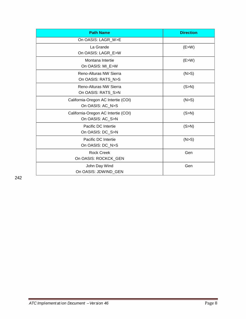
The following table shows the Paths for which BPA uses the Rated System Path methodology. 240
Table 1 241
Path Name Direction
Northern Intertie Total On Oasis: NI_TOTL_N>S
(N>S)
Northern Intertie Total On OASIS: NI_TOTL_S>N
(S>N)
West of Hatwai On OASIS: WOH_E>W
(E>W)
Montana-Northwest West of Garrison
On OASIS: WOGARR_E>W
(E>W)
Montana-Northwest West of Garrison
On OASIS: WOGARR_W>E
(W>E)
La Grande (W>E)
ATC Implementation Document – Version 46 Page 8
Path Name Direction
On OASIS: LAGR_W>E
La Grande On OASIS: LAGR_E>W
(E>W)
Montana Intertie On OASIS: MI_E>W
(E>W)
Reno-Alturas NW Sierra On OASIS: RATS_N>S
(N>S)
Reno-Alturas NW Sierra On OASIS: RATS_S>N
(S>N)
California-Oregon AC Intertie (COI) On OASIS: AC_N>S
(N>S)
California-Oregon AC Intertie (COI) On OASIS: AC_S>N
(S>N)
Pacific DC Intertie On OASIS: DC_S>N
(S>N)
Pacific DC Intertie On OASIS: DC_N>S
(N>S)
Rock Creek On OASIS: ROCKCK_GEN
Gen
John Day Wind On OASIS: JDWIND_GEN
Gen
242
ATC Implementation Document – Version 46 Page 9
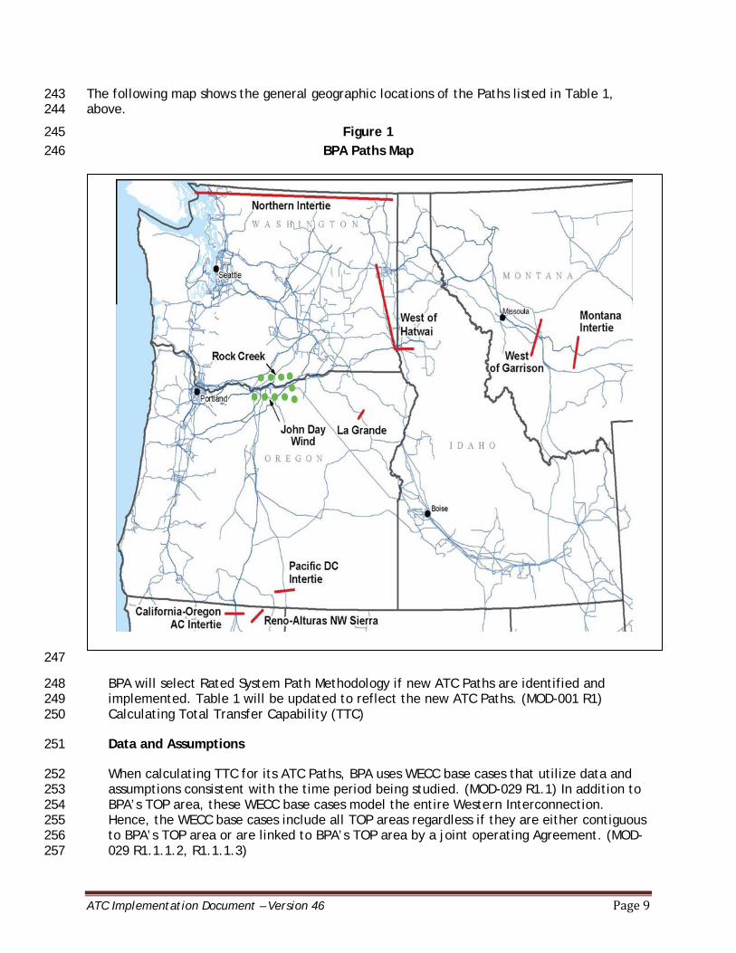
The following map shows the general geographic locations of the Paths listed in Table 1, 243 above. 244
Figure 1 245 BPA Paths Map 246
247
BPA will select Rated System Path Methodology if new ATC Paths are identified and 248 implemented. Table 1 will be updated to reflect the new ATC Paths. (MOD-001 R1) 249 Calculating Total Transfer Capability (TTC) 250
Data and Assumptions 251
When calculating TTC for its ATC Paths, BPA uses WECC base cases that utilize data and 252 assumptions consistent with the time period being studied. (MOD-029 R1.1) In addition to 253 BPA’s TOP area, these WECC base cases model the entire Western Interconnection. 254 Hence, the WECC base cases include all TOP areas regardless if they are either contiguous 255 to BPA’s TOP area or are linked to BPA’s TOP area by a joint operating Agreement. (MOD-256 029 R1.1.1.2, R1.1.1.3) 257
ATC Implementation Document – Version 46 Page 10
TOP areas contiguous with BPA’s TOP area include (MOD-029 R1.1.1.2): 258
• Avista Corporation (AVA) 259 • BC Hydro (BCH) 260 • California Independent System Operator (CAISO) 261 • City of Tacoma, Department of Public Utilities, Light Division 262 • Eugene Water and Electric Board (EWEB) 263 • Idaho Power Company (IPCO) 264 • Los Angeles Department of Water and Power (LADWP) 265 • NorthWestern Energy (NWMT) 266 • Sierra Pacific (doing business as NV Energy ) 267 • PacifiCorp (PAC) 268 • Pend Oreille County Public Utility District No. 1 269 • Portland General Electric (PGE) 270 • Public Utility District No. 1 of Chelan County 271 • Public Utility District No. 1 of Clark County 272 • Public Utility District No. 1 of Snohomish County 273 • Public Utility District No. 2 of Grant County, Washington 274 • PUD No. 1 of Douglas County 275 • Puget Sound Energy, Inc. (PSEI) 276 • Seattle City Light (SCL) 277
BPA uses the following data and assumptions in the WECC base cases when calculating 278 TTCs for its ATC Paths: 279
BPA models all existing System Elements in their normal operating condition for the 280 assumed initial conditions, up to the time horizon in which BPA begins modeling 281 outages (see Section V, “Outages,” beginning on p. 6). (MOD-029 R1.1.2) 282
The WECC base cases include generators and phase shifters that meet the guidelines 283 set out in the WECC Data Preparation Manual. (MOD-029 R1.1.3) (MOD-029 R1.1.4) 284
BPA uses the seasonal Load forecasts contained in the WECC base cases for each BA. 285 (MOD-029 R1.1.5) 286
Generation and Transmission Facility additions and retirements within the WECC 287 footprint are included in the WECC seasonal operating base cases for the season in 288 which they are energized/de-energized, respectively. BPA engineers modify the WECC 289 base cases to reflect the actual dates of energization/de-energization. (MOD-029 290 R1.1.6, R1.1.7) 291
The WECC base cases include Facility Ratings as provided to WECC by the Transmission 292 Owners and Generator Owners. (MOD-029 R1.2) 293
If Facility changes are made by BPA or another entity, then the base cases will be 294 updated to reflect these changes with a Mid-Season update. (MOD-029 R1.1, R1.2) 295
ATC Implementation Document – Version 46 Page 11
The approved seasonal operating base cases that include the Facility changes will not 296 be used until 0 to 16 days prior to the energization or implementation of the Facility 297 change. (MOD-029 R1.1, R1.2) 298
For periods beyond two weeks, the WECC base cases will be updated as necessary to 299 perform seasonal studies for the current or upcoming season in accordance with the 300 current BPA study processes. (MOD-029 R1.1, R1.2, R2.1) 301
For stability limited paths, except West of Garrison and Northern Intertie South to 302 North, BPA uses the minimum SOL from the relevant seasonal studies when there are 303 no studied outages to set the TTC of the path for the corresponding seasonal time 304 periods. 305
For West of Garrison, for the seasons or time periods in which the seasonal studies 306 have not been completed, the most recent year’s seasonal study results will be used 307 for setting the TTC for the relevant Path. For all time periods, when there are no 308 studied outages, BPA uses a TTC of 2000 MW E>W and the maximum value from the 309 relevant studies to set the seasonal TTC of the Path W>E. 310
For Northern Intertie South to North, for the seasons or time periods in which the 311 seasonal studies have not been completed, the most recent year’s seasonal study 312 results will be used for setting the TTC for the relevant Path. BPA uses the minimum 313 SOL from the relevant seasonal studies to set the TTC of the Path for periods from the 314 next day and beyond. For the Real-time horizon, when there are no studied outages, 315 BPA uses the maximum SOL from the relevant seasonal studies to set the TTC of the 316 Path. 317
For thermally limited paths, BPA uses a TTC from the relevant seasonal studies when 318 there are no studied outages to set the TTC of the path for the corresponding seasonal 319 time periods. 320
BPA models Special Protection Systems (BPA uses the term Remedial Action Schemes 321 or RAS) that currently exist or are projected for implementation within the studied 322 time horizon. (MOD-029 R1.1.8) 323
The WECC base cases include all series compensation for each line at the expected 324 operating level. (MOD-029 R1.1.9) 325
BPA uses no other modeling requirements for calculating TTC in addition to those 326 specified in this document. (MOD-029 R1.1.10) 327
Process to Determine TTC 328
BPA adjusts generation and Load levels within the WECC power-flow base cases to determine 329 the TTC that can be simulated for each of its ATC Paths, while at the same time satisfying all 330 planning criteria contingencies, as follows: 331
BPA studies single and multiple contingencies that are relevant to the Path being studied. 332 (MOD-029 R2.1) 333

ATC Implementation Document – Version 46 Page 12
When modeling normal conditions, BPA models all Transmission Elements in BPA’s BAA and 334 adjacent BAAs at or below 100 percent of their continuous Rating. (MOD-029 R2.1.1) 335
When modeling contingencies for stability limited paths, refer to the current version of 336 “Peak Reliability System Operating Limits Methodology for the Operations Horizon” 337 (PeakRC SOL Methodology) posted on Peak Reliability’s website https://www.peakrc.com 338 for a detailed description of how BPA determines SOLs used to set TTCs. (MOD-029 R2.1.2) 339
When modeling contingencies for thermally limited paths, BPA determines TTCs by 340 stressing the system until flows exceed emergency Facility Ratings or voltages fall outside 341 emergency system voltage limits (i.e., the post-Contingency state). If a facility does not 342 have an emergency Facility Rating, the normal Facility Rating is used. If there is no 343 emergency system voltage limit, the normal system voltage limit is used. (MOD-029 344 R2.1.2) By meeting the criteria in the PeakRC SOL Methodology, uncontrolled separation 345 should not occur. (MOD-029 R2.1.3) 346
The Available Transfer Capability (ATC) Paths listed below, for which BPA uses the Rated 347 System Path Methodology, have TTCs from studies in only the prevailing direction of flow. 348 The TTC values for the non-prevailing direction of flow are determined as follows: 349
For paths: West Of Hatwai, Columbia Injection, Wanapum Injection, South Of Custer-350 North Of Echo Lake, South Of Boundary, West Of Lower Monumental, North of John Day, 351 and the Montana Intertie; 352
Use the prevailing flow direction TTC as the non-prevailing flow direction TTC 353
For paths: Paul-Allston, Raver-Paul, West Of McNary, West Of Slatt, and West Of John 354 Day; 355
Use the non-RAS TTC as the non-prevailing flow direction TTC 356
For West of McNary also address North of John Day as follows; 357
Use the non-RAS TTC as the non-prevailing flow direction TTC for West of McNary. 358 The non-prevailing direction TTC for North of John Day is based on the TTC 359 addressed in the COI/PDCI study for this time period. 360
All of BPA’s other ATC Paths have either reliability-based SOLs or TTCs in both the 361 prevailing and non-prevailing directions of flow. (MOD-029 R2.2) 362
For ATC Paths where TTC varies due to simultaneous interaction with one or more other 363 Paths, BPA develops a nomogram, represented either by an equation or its graphical 364 representation, describing the interaction of the Paths and the resulting TTC under 365 specified conditions. BPA then calculates a value, based on that nomogram and 366 forecasted System conditions for the time period studied, to develop its TTC values for 367 the affected ATC Paths. (MOD-029 R2.4) 368
BPA or the adjacent Path TOP identifies when the new or increased TTC for an ATC Path 369 being studied by BPA or the adjacent Path TOP has an adverse impact on the TTC value of 370 another existing Path by modeling the flow on the Path being studied at its proposed new 371 TTC level, while simultaneously modeling the flow on the existing Path at its TTC level. In 372 doing so, BPA or the adjacent Path TOP honors the reliability criteria described above. 373 BPA or the adjacent Path TOP includes the resolution of this adverse impact in its study 374 report for the ATC Path. (MOD-029 R2.5) 375
ATC Implementation Document – Version 46 Page 13
BPA has Transmission Ownership Agreements where multiple ownerships of Transmission 376 rights exist on an ATC Path. TTC for the affected ATC paths is allocated according to 377 contractual ownership rights. See section IV, “Allocation Processes” for further details. 378 (MOD-029 R2.6) 379
BPA does not have any ATC Paths whose Ratings were established, known, and used in 380 operation since January 1, 1994. (MOD-029 R2.7) 381
BPA creates a study report that describes the TTC applicable to the outages during the 382 studied time period and includes the limiting Contingencies and the limiting cause for the 383 calculated TTC. The PeakRC SOL Methodology document (PeakRC SOL Methodology posted 384 at: https://www.peakrc.com ) defines the steps taken and assumptions BPA used to 385 determine TTC for each stability limited ATC path. BPA creates a study report for each 386 study it performs. The study report relies on the basic assumptions included in PeakRC 387 SOL methodology and identifies any changes to those basic assumptions. (MOD-029 R2.8) 388
As described in Section III, “Overview,” information regarding TTCs is shared electronically 389 between the appropriate BPA organizations within seven calendar days of the finalization of 390 the study report for the TTCs. BPA sends a notice to all TSPs for the ATC Paths listed in Table 391 1 where there are multiple TSPs prior to limitations in TTCs. (MOD-029 R4) 392
These notices are called Notices of Planned Path Limitation. Where BPA has performed a 393 study, the notice states that the TTC study report is available to TSPs for the specific Path 394 within seven calendar days upon request to [email protected] with TTC Study Report 395 Request in the subject line. Use the TTC Study Report Request Form found on BPA’s 396 website shown below to submit the request. 397
http://transmission.bpa.gov/business/atc_methodology/ 398
An ATC Path for which BPA does not perform studies to determine the most current value of 399 TTC is Reno – Alturas NW Sierra (RATS). For RATS, NV Energy determines TTC. The TTC 400 Ratings are provided to BPA and BPA then sends a Notice of Planned Path Limitation. (MOD-401 029 R3) 402
Calculating Firm Transmission Service 403
Calculating Firm Existing Transmission Commitments (ETCF) 404
When calculating ETCF for all time periods for its ATC Paths, BPA uses the following 405 algorithm as specified in MOD-029 R5: 406
ETCF = NLF + NITSF + GFF + PTPF + RORF + OSF 407
Where: 408
NLF is the firm capacity set aside to serve peak Native Load forecast commitments for the 409 time period being calculated, to include losses and Load growth not otherwise included in 410 TRM or CBM. 411
ATC Implementation Document – Version 46 Page 14
BPA does not use the NLF component of the ETCF calculation for any of its ATC Paths. 412 All of BPA’s firm Transmission obligations are included in contracts, Agreements and 413 obligations captured in the NITSF, PTPF and GFF components of this algorithm. 414 Therefore BPA sets NLF at zero for all of its ATC Paths for all time periods. 415
NITSF is the firm capacity reserved for Network Integration Transmission Service serving 416 Load, to include losses and Load growth. 417
For BPA’s ATC Paths where NITSF commitments exist to serve Network Load outside 418 BPA’s BAA, the firm capacity set aside for NITSF is equal to the Load forecast, which 419 includes losses and Load growth, minus generation outside BPA’s BAA that is 420 designated to serve that Load. For BPA’s ATC Paths where NITSF commitments exist to 421 serve Network Load inside BPA’s BAA from a forecasted or designated network 422 resource that impacts the ATC Path, the firm capacity set aside for NITSF is equal to 423 the amount the resource is forecasted/designated for. 424
GFF is the firm capacity set aside for grandfathered Transmission Service and contracts for 425 energy and/or Transmission Service, where executed prior to the effective date of BPA’s 426 Open Access Transmission Tariff (OATT). 427
The amount of GFF BPA sets aside is based on the terms of each individual contract. 428
PTPF is the firm capacity reserved for confirmed Point-to-Point Transmission Service and 429 is equal to the sum of the PTPF contract Demands. 430
In BPA’s calculations, PTPF is equal to the sum of the MW Demands of PTPF 431 reservations or schedules. In some cases, BPA has PTPF contracts that give customers 432 the right to schedule between multiple Points of Receipt (PORs) and Points of Delivery 433 (PODs). However, the customer can only schedule up to the MW amount specified in 434 their contract. Multiple reservations are created for these special cases to allow BPA 435 to model each POR-to-POD combination. The amount set aside for these cases does 436 not exceed the total PTPF capacity specified in the contracts. 437
RORF is the firm capacity reserved for roll-over rights for contracts granting Transmission 438 Customers the right of first refusal to take or continue to take Transmission Service when 439 the Transmission Customer’s Transmission Service contract expires or is eligible for 440 renewal. 441
BPA assumes that all of its Transmission Service Agreements eligible to roll-over in the 442 future will be rolled over. Therefore, RORF is equal to the sum of the NITSF, GFF and 443 PTPF obligations that are eligible for roll-over rights. If a Transmission Customer 444 chooses not to exercise its roll-over rights by the required deadline, BPA no longer 445 holds out capacity for roll-over rights for that Transmission Customer. 446
OSF is the firm capacity reserved for any other service(s), contract(s), or Agreement(s) not 447 specified above using Firm Transmission Service. 448
BPA has no other services beyond those specified above. Therefore BPA sets OSF at 449 zero for all of its ATC Paths for all time periods. 450
As a result, BPA calculates ETCF for its ATC Paths for all time periods as follows: 451

ATC Implementation Document – Version 46 Page 15
ETCF = NITSF + GFF + PTPF + RORF 452
While BPA includes all of the components described above in ETCF, BPA accounts for NITSF, 453 GFF, PTPF and RORF in its ATC calculations using different variables. Descriptions of the 454 variables for ATCF calculations begin on p. 15 and for ATCNF calculations, p.21. 455
Calculating Firm Available Transfer Capability (ATCF) 456
When calculating ATCF for its ATC Paths for all time periods, BPA uses the following 457 algorithm (MOD-029 R7): 458
ATCF = TTC - ETC
F - CBM - TRM + Postbacks
F + Counterflows
F 459
Where: 460
ATCF is the firm Available Transfer Capability for the ATC Path for that period. 461
TTC is the Total Transfer Capability for that ATC Path for that time period. 462
See “Process to Determine TTC” beginning on p. 11, for a description of how BPA 463 determines TTC. 464
ETCF is the sum of existing firm commitments for that ATC Path during that period. 465
For ATCF calculations for all time periods, BPA further divides ETCF into the following 466 algorithm in order to capture both its firm Long-Term and Short-Term Reservations: 467
ETCF = LRES + SRES + LETC - SADJ/ETC Adjustments 468
Where: 469
LRES is the sum of the NITSF, PTPF, RORF and GFF Long-Term Reservations. 470
SRES is the sum of the PTPF Short-Term Reservations. 471
LETC is used to make two different adjustments to ETCF. The first adjustment is 472 made to ensure that the amount of PTPF capacity BPA sets aside in the LRES 473 variable for contracts where BPA gives customers the right to schedule the 474 capacity reserved between multiple PORs and PODs does not exceed the total PTPF 475 capacity specified in those contracts. 476
The second adjustment is made only on the West of Hatwai E>W Path. On this ATC 477 Path, BPA uses LETC to hold out NITSF capacity for the Western Montana hydro 478 projects (Albeni Falls, Libby, Hungry Horse and Dworshak) located east of West of 479 Hatwai to serve Network Load west of West of Hatwai, since no reservation exists 480 for this NITSF obligation. 481
ATC Implementation Document – Version 46 Page 16
SADJ/ETC Adjustments is the variable BPA uses to make adjustments to ETCF not 482 captured in LRES or SRES. On the West of Garrison Path, BPA has two PTPF Long-483 Term Reservations, captured in LRES, that hold out capacity in the E>W direction. 484 However, the energy associated with these reservations is affected by a parallel 485 path and flows in the W>E direction as well. SADJ/ETC Adjustments is used to hold 486 out capacity in the W>E direction to accurately account for this flow as an ETCF 487 adjustment. 488
BPA applies another such adjustment to allow for deferral competitions, as 489 required in Section 17.7 of BPA’s OATT. When a deferral reservation is confirmed, 490 BPA applies an ETC adjustment to hold out transfer capability for the time period 491 deferred, starting at the latter of five months out or the service commencement 492 date of the original reservation, to allow for a competition. At four months out, if 493 no competition is identified, the ETC adjustment is modified to post back transfer 494 capability for the fourth month out. 495
BPA also uses SADJ/ETC adjustments to ensure accurate accounting of ETCF. These 496 adjustments may be performed to account for situations such as data modeling 497 corrections, and will be noted in the descriptions of the adjustments. 498
BPA also uses SADJ adjustments on the Northern Intertie Path 3 S>N. These SADJ 499 adjustments are used to reflect the TRM across this path that accounts for 500 uncertainties on the path caused by simultaneous interaction with paths COI and 501 NOH. 502
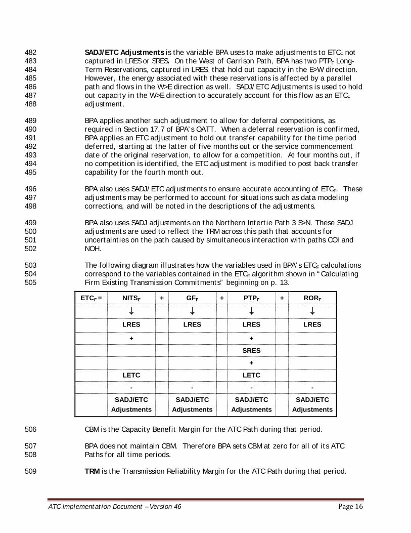
The following diagram illustrates how the variables used in BPA’s ETCF calculations 503 correspond to the variables contained in the ETCF algorithm shown in “Calculating 504 Firm Existing Transmission Commitments” beginning on p. 13. 505
ETCF = NITSF + GFF + PTPF + RORF
↓ ↓ ↓ ↓
LRES LRES LRES LRES
+ +
SRES
+
LETC LETC
- - - -
SADJ/ETC Adjustments
SADJ/ETC Adjustments
SADJ/ETC Adjustments
SADJ/ETC Adjustments
CBM is the Capacity Benefit Margin for the ATC Path during that period. 506
BPA does not maintain CBM. Therefore BPA sets CBM at zero for all of its ATC 507 Paths for all time periods. 508
TRM is the Transmission Reliability Margin for the ATC Path during that period. 509
ATC Implementation Document – Version 46 Page 17
BPA maintains TRM on the Northern Intertie Path as described in its TRMID for all 510 time periods. BPA does not maintain TRM in its ATC calculation for any other ATC 511 Paths. Therefore, BPA sets TRM at zero for all remaining ATC Paths for all time 512 periods. 513
PostbacksF are changes to ATCF due to a change in the use of Transmission Service 514
for that period. 515
Because BPA automatically recalculates ETCF whenever there is a reduction in LRES 516 or SRES, BPA does not use PostbacksF for calculating ATCF on any of its ATC Paths. 517 Therefore BPA sets PostbacksF at zero for all of its ATC Paths for all time periods. 518
CounterflowsF are adjustments to ATCF. 519
BPA does not include confirmed Transmission reservations, expected interchange 520 or internal flow counter to the direction of the ATC Path being calculated in its 521 ATCF calculations. BPA’s rationale is that it does not want to offer firm transfer 522 capability due to counterflow that may not be scheduled as this could lead to 523 Curtailments of Firm Transmission Service in the Real-time horizon. (MOD-001 524 R3.2) Therefore BPA sets CounterflowsF at zero for all of its ATC Paths for all time 525 periods. 526
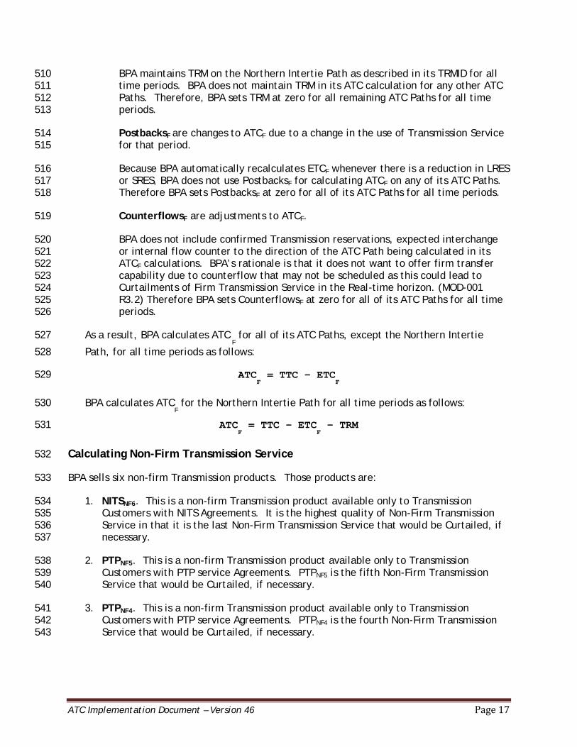
As a result, BPA calculates ATC F for all of its ATC Paths, except the Northern Intertie 527
Path, for all time periods as follows: 528
ATCF = TTC - ETC
F 529
BPA calculates ATCF for the Northern Intertie Path for all time periods as follows: 530
ATCF = TTC - ETC
F - TRM 531
Calculating Non-Firm Transmission Service 532
BPA sells six non-firm Transmission products. Those products are: 533
1. NITSNF6. This is a non-firm Transmission product available only to Transmission 534 Customers with NITS Agreements. It is the highest quality of Non-Firm Transmission 535 Service in that it is the last Non-Firm Transmission Service that would be Curtailed, if 536 necessary. 537
2. PTPNF5. This is a non-firm Transmission product available only to Transmission 538 Customers with PTP service Agreements. PTPNF5 is the fifth Non-Firm Transmission 539 Service that would be Curtailed, if necessary. 540
3. PTPNF4. This is a non-firm Transmission product available only to Transmission 541 Customers with PTP service Agreements. PTPNF4 is the fourth Non-Firm Transmission 542 Service that would be Curtailed, if necessary. 543

ATC Implementation Document – Version 46 Page 18
4. PTPNF3. This is a non-firm Transmission product available only to Transmission 544 Customers with PTP service Agreements. PTPNF3 is the third Non-Firm Transmission 545 Service that would be Curtailed, if necessary. 546
5. PTPNF2. This is a non-firm Transmission product available only to Transmission 547 Customers with PTP service Agreements. PTPNF2 is the second Non-Firm Transmission 548 Service that would be Curtailed, if necessary. 549
6. PTPNF1. This is a non-firm Transmission product available only to Transmission 550 Customers with PTP service Agreements. PTPNF1 is the first Non-Firm Transmission 551 Service that would be Curtailed, if necessary (i.e., this Transmission Service has the 552 highest likelihood of being Curtailed). 553
BPA calculates ETCNF and ATCNF for each of these products. 554
Calculating Non-Firm Existing Transmission Commitments (ETCNF) 555
BPA calculates ETCNF for all time periods for an ATC Path using the following algorithm as 556 specified in MOD-029 R6: 557
ETCNF = NITSNF + GFNF + PTPNF + OSNF 558
Where: 559
NITSNF is the non-firm capacity set aside for Network Integration Transmission Service 560 serving Load (i.e., secondary service), to include losses and Load growth not otherwise 561 included in TRM or CBM. 562
In BPA’s calculations, this is NITSNF6. It does not include losses or Load growth, since 563 losses and Load growth are already set aside as firm capacity in NITSF. 564
GFNF is the non-firm capacity set aside for grandfathered Transmission Service and 565 contracts for energy and/or Transmission Service, where executed prior to the effective 566 date of BPA’s OATT. 567
BPA has no grandfathered Non-Firm Transmission Service obligations. Therefore BPA 568 sets GFNF at zero for all of its ATC Paths for all time periods. 569
PTPNF is non-firm capacity reserved or scheduled for confirmed PTP Transmission Service. 570
In BPA’s calculations, this includes PTPNF5, PTPNF4, PTPNF3, PTPNF2 and PTPNF1. 571
OSNF is the non-firm capacity reserved for any other service(s), contract(s), or 572 Agreement(s) not specified above using Non-Firm Transmission Service. 573
BPA has no other services beyond those specified above. Therefore BPA sets OSNF at 574 zero for all of its ATC Paths for all time periods. 575
As a result, BPA calculates ETCNF for its ATC Paths for all time periods as follows: 576
ETCNF = NITSNF + PTPNF 577
ATC Implementation Document – Version 46 Page 19
While BPA includes all of the components described above in ETCNF, BPA accounts for NITSNF 578 and PTPNF in its ATCNF calculations using different variables. A description of the variables 579 used begins on p.20. 580
Calculating Non-Firm Available Transfer Capability (ATCNF) 581
BPA uses different algorithms to calculate ATCNF, ETCF, ETCNF and PostbacksNF for two time 582 horizons for all of its ATC Paths: Real-time and beyond Real-time. The Real-time horizon 583 begins at 10 p.m. on the pre-schedule day for the 24 hours in the next day. ETCF and ETCNF 584 for the Real-Time horizon are calculated using schedules and reservations that have not yet 585 been scheduled. The beyond Real-time horizon includes hourly for the hours after those 586 included in the Real-time period as well as daily and monthly calculations. ETCF and ETCNF for 587 the time horizon beyond Real-time are calculated using reservations. 588
BPA calculates ETCNF and ATCNF for the six non-firm Transmission products associated with 589 NERC Curtailment priorities (described on p.20) as follows: 590
1. ATCNF6: ATCNF6 is calculated for the NITSNF6 product. ETCNF in this equation only 591 includes NITSNF6. 592
2. ATCNF5: ATCNF5 is calculated for the PTPNF5 product. ETCNF in this equation includes 593 NITSNF6 and PTPNF5. 594
3. ATCNF4: ATCNF4 is calculated for the PTPNF4 product. ETCNF in this equation includes 595 NITSNF6, PTPNF5 and PTPNF4. 596
4. ATCNF3: ATCNF3 is calculated for the PTPNF3 product. ETCNF in this equation includes 597 NITSNF6, PTPNF5, PTPNF4, and PTPNF3. 598
5. ATCNF2: ATCNF2 is calculated for the PTPNF2 product. ETCNF in this equation includes 599 NITSNF6, PTPNF5, PTPNF4, PTPNF3 and PTPNF2. 600
6. ATCNF1: ATCNF1 is calculated for the PTPNF1 product. ETCNF in this equation includes 601 NITSNF6, PTPNF5, PTPNF4, PTPNF3, PTPNF2 and PTPNF1. 602
The following section describes how BPA calculates ATCNF for each time period. 603
When calculating ATCNF for its ATC paths for the two time horizons described above, BPA uses 604 the following algorithm as specified in MOD-029 R8: 605
ATCNF = TTC – ETCF – ETCNF – CBMS – TRMU + PostbacksNF + CounterflowNF 606
Where: 607
ATCNF is the non-firm Available Transfer Capability for the ATC Path for that period. 608
As previously described, BPA calculates six ATCNF values, one for each of its six non-firm 609 Transmission products. 610
TTC is the Total Transfer Capability of the ATC Path for that period. 611

ATC Implementation Document – Version 46 Page 20
See “Calculating Total Transfer Capability” beginning on p. 13 for a description of BPA’s 612 process to determine TTC. 613
ETCF is the sum of existing firm commitments for the ATC Path during that period. 614
BPA uses different algorithms to calculate ETCF for all of its ATC Paths for the time 615 horizon beyond Real-time and the Real-time horizon. 616
ETCF for the Time Horizon Beyond Real-Time 617 For ATCNF calculations for the time horizon beyond Real-time, BPA further divides ETCF 618 into the following algorithm in order to capture both its firm Long-Term and Short-Term 619 Reservations: 620
ETCF = LRES + SRES - SADJ/ETC Adjustments + LETC 621
Where: 622
LRES is the sum of the NITSF, PTPF, RORF and GFF Long-Term Reservations. 623
SRES is the sum of the PTPF Short-Term Reservations. 624
SADJ/ETC Adjustments is the variable used to make adjustments to ETCF not captured in 625 LRES or SRES. On the West of Garrison Path, BPA has two PTPF reservations, captured in 626 LRES, that hold out capacity in the E>W direction. However, the energy associated with 627 these reservations is affected by a parallel path and flows in the W>E direction as well. 628 SADJ/ETC Adjustments is used to hold out capacity in the W>E direction to accurately account 629 for this flow as an ETCF adjustment. 630
In addition, BPA uses SADJ adjustments on the Northern Intertie Path 3 S>N. These SADJ 631 adjustments are used to reflect the TRM across this path that accounts for uncertainties on 632 the path caused by simultaneous interaction with paths COI and NOH. 633
BPA applies another such adjustment to allow for deferral competitions, as required in 634 Section 17.7 of BPA’s OATT. When a deferral reservation is confirmed, BPA applies an ETC 635 adjustment to hold out transfer capability for the time period deferred, starting at the latter 636 of five months out or the service commencement date of the original reservation, to allow for 637 a competition. At four months out, if no competition is identified, the ETC adjustment is 638 modified to add back transfer capability for the fourth month out. 639
BPA also uses SADJ/ETC adjustments to ensure accurate accounting of ETCF. These 640 adjustments may be performed to account for situations such as data modeling corrections, 641 and will be noted in the descriptions of the adjustments. 642
LETC is used to make two different adjustments to ETCF. The first adjustment is made to 643 ensure that the amount of PTPF capacity BPA sets aside in the LRES variable for contracts 644 where BPA gives customers the right to schedule the capacity reserved between multiple 645 PORs and PODs does not exceed the total PTPF capacity specified in those contracts. 646
ATC Implementation Document – Version 46 Page 21
The second adjustment is made only on the West of Hatwai E>W Path. On this ATC Path BPA 647 uses LETC to hold out NITSF capacity for the Western Montana hydro projects (Albeni Falls, 648 Libby, Hungry Horse and Dworshak) located east of West of Hatwai to serve Network Load 649 west of West of Hatwai, since no reservation exists for this NITSF obligation. 650
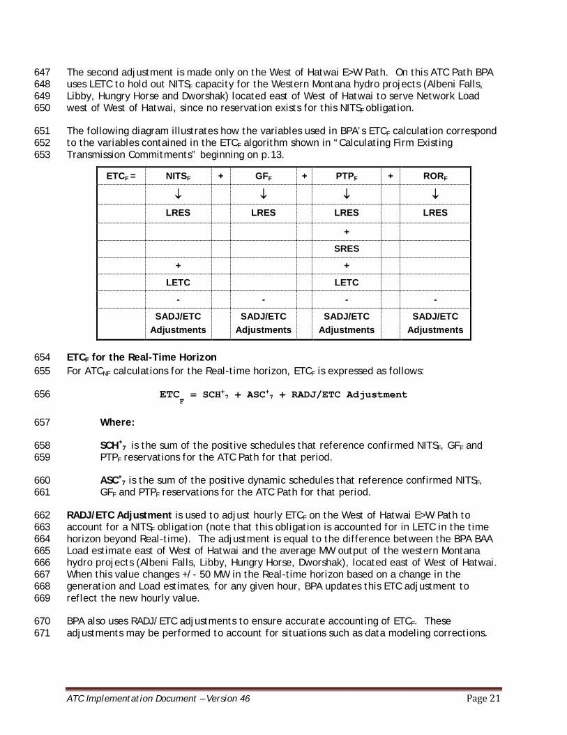
The following diagram illustrates how the variables used in BPA’s ETCF calculation correspond 651 to the variables contained in the ETCF algorithm shown in “Calculating Firm Existing 652 Transmission Commitments” beginning on p.13. 653
ETCF = NITSF + GFF + PTPF + RORF
↓ ↓ ↓ ↓
LRES LRES LRES LRES
+
SRES
+ +
LETC LETC
- - - -
SADJ/ETC Adjustments
SADJ/ETC Adjustments
SADJ/ETC Adjustments
SADJ/ETC Adjustments
ETCF for the Real-Time Horizon 654 For ATCNF calculations for the Real-time horizon, ETCF is expressed as follows: 655
ETCF = SCH+7 + ASC+7 + RADJ/ETC Adjustment 656
Where: 657
SCH+7
is the sum of the positive schedules that reference confirmed NITSF, GFF and 658
PTPF reservations for the ATC Path for that period. 659
ASC+7 is the sum of the positive dynamic schedules that reference confirmed NITSF, 660
GFF and PTPF reservations for the ATC Path for that period. 661
RADJ/ETC Adjustment is used to adjust hourly ETCF on the West of Hatwai E>W Path to 662 account for a NITSF obligation (note that this obligation is accounted for in LETC in the time 663 horizon beyond Real-time). The adjustment is equal to the difference between the BPA BAA 664 Load estimate east of West of Hatwai and the average MW output of the western Montana 665 hydro projects (Albeni Falls, Libby, Hungry Horse, Dworshak), located east of West of Hatwai. 666 When this value changes +/- 50 MW in the Real-time horizon based on a change in the 667 generation and Load estimates, for any given hour, BPA updates this ETC adjustment to 668 reflect the new hourly value. 669
BPA also uses RADJ/ETC adjustments to ensure accurate accounting of ETCF. These 670 adjustments may be performed to account for situations such as data modeling corrections. 671
ATC Implementation Document – Version 46 Page 22
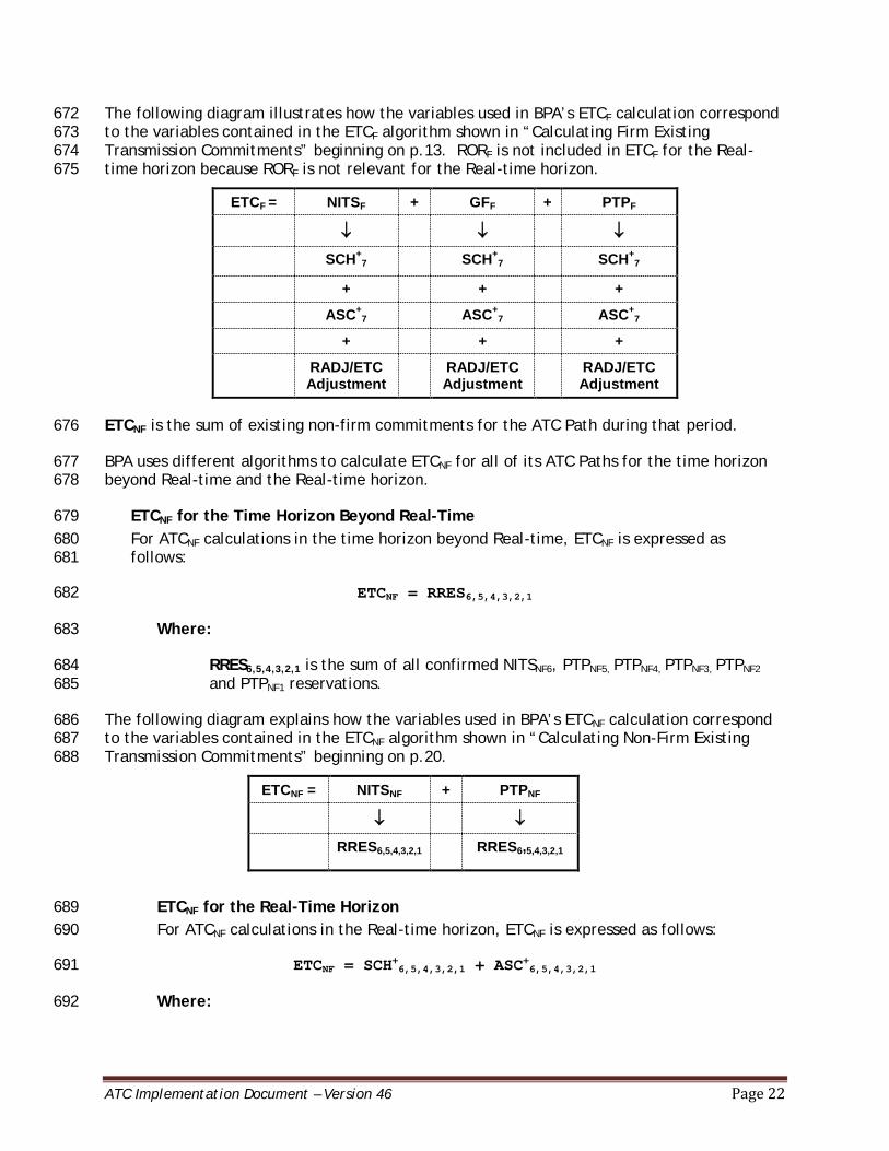
The following diagram illustrates how the variables used in BPA’s ETCF calculation correspond 672 to the variables contained in the ETCF algorithm shown in “Calculating Firm Existing 673 Transmission Commitments” beginning on p.13. RORF is not included in ETCF for the Real-674 time horizon because RORF is not relevant for the Real-time horizon. 675
ETCF = NITSF + GFF + PTPF
↓ ↓ ↓
SCH+7 SCH+
7 SCH+7
+ + +
ASC+7 ASC+
7 ASC+7
+ + +
RADJ/ETC Adjustment
RADJ/ETC Adjustment
RADJ/ETC Adjustment
ETCNF is the sum of existing non-firm commitments for the ATC Path during that period. 676
BPA uses different algorithms to calculate ETCNF for all of its ATC Paths for the time horizon 677 beyond Real-time and the Real-time horizon. 678
ETCNF for the Time Horizon Beyond Real-Time 679 For ATCNF calculations in the time horizon beyond Real-time, ETCNF is expressed as 680 follows: 681
ETCNF = RRES6,5,4,3,2,1 682
Where: 683
RRES6,5,4,3,2,1 is the sum of all confirmed NITSNF6, PTPNF5, PTPNF4, PTPNF3, PTPNF2 684 and PTPNF1 reservations. 685
The following diagram explains how the variables used in BPA’s ETCNF calculation correspond 686 to the variables contained in the ETCNF algorithm shown in “Calculating Non-Firm Existing 687 Transmission Commitments” beginning on p.20. 688
ETCNF = NITSNF + PTPNF
↓ ↓
RRES6,5,4,3,2,1 RRES6,5,4,3,2,1
ETCNF for the Real-Time Horizon 689 For ATCNF calculations in the Real-time horizon, ETCNF is expressed as follows: 690
ETCNF = SCH+6,5,4,3,2,1 + ASC+6,5,4,3,2,1 691
Where: 692
ATC Implementation Document – Version 46 Page 23
SCH+6,5,4,3,2,1 is the sum of the positive Demands of schedules referenced to 693
confirmed NITSNF6, PTPNF5, PTPNF4, PTPNF3, PTPNF2 and PTPNF1 reservations, plus 694 the sum of the positive Demands of confirmed NITSNF6, PTPNF5, PTPNF4, PTPNF3, 695 PTPNF2 and PTPNF1 reservations that have not yet been scheduled. Once these 696 reservations are scheduled, the schedule is used for ETCNF, thereby adding back 697 the difference between the reservation and schedule amounts to ATCNF. 698
ASC+6,5,4,3,2,1 is the sum of positive Demands of dynamic schedules referenced 699
to confirmed NITSNF6, PTPNF5, PTPNF4, PTPNF3, PTPNF2 and PTPNF1 reservations for 700 the ATC Path. 701
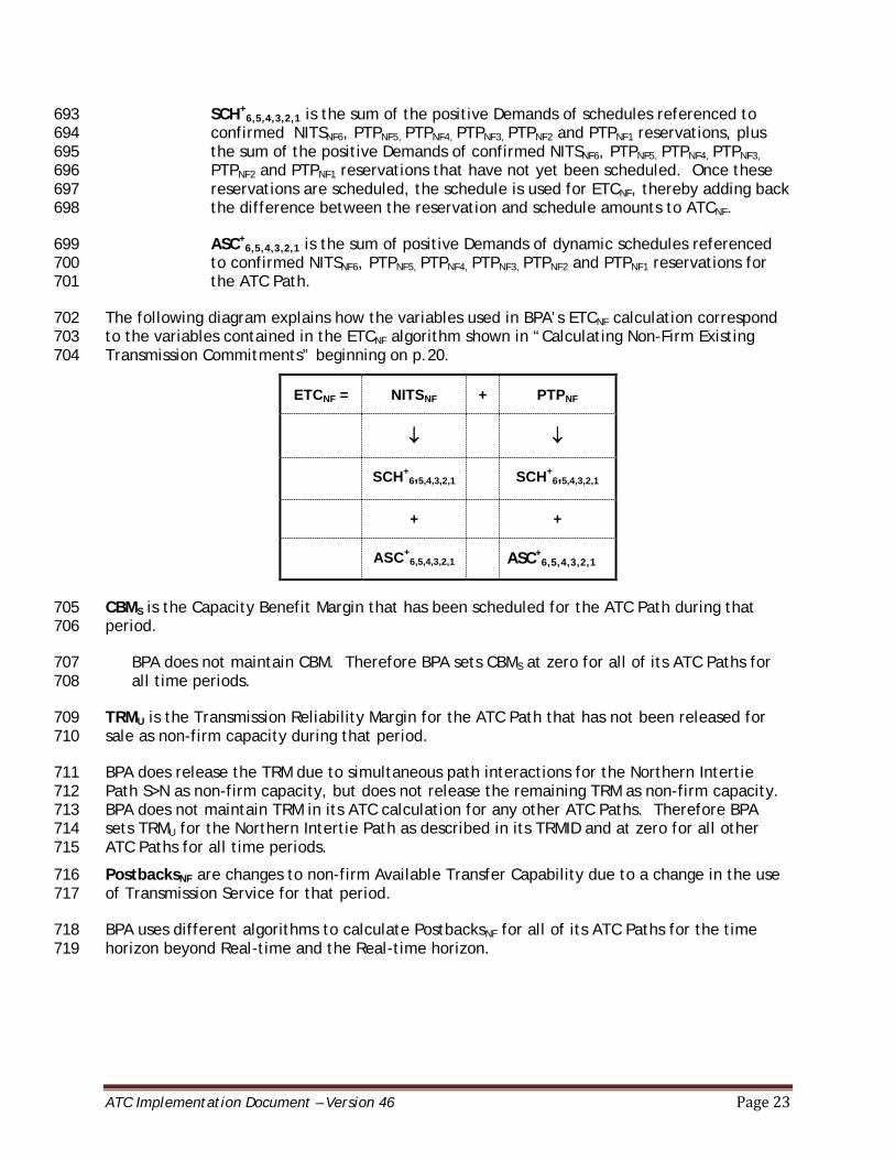
The following diagram explains how the variables used in BPA’s ETCNF calculation correspond 702 to the variables contained in the ETCNF algorithm shown in “Calculating Non-Firm Existing 703 Transmission Commitments” beginning on p.20. 704
ETCNF = NITSNF + PTPNF
↓ ↓
SCH+6,5,4,3,2,1 SCH+
6,5,4,3,2,1
+ +
ASC+6,5,4,3,2,1 ASC+
6,5,4,3,2,1
CBMS is the Capacity Benefit Margin that has been scheduled for the ATC Path during that 705 period. 706
BPA does not maintain CBM. Therefore BPA sets CBMS at zero for all of its ATC Paths for 707 all time periods. 708
TRMU is the Transmission Reliability Margin for the ATC Path that has not been released for 709 sale as non-firm capacity during that period. 710
BPA does release the TRM due to simultaneous path interactions for the Northern Intertie 711 Path S>N as non-firm capacity, but does not release the remaining TRM as non-firm capacity. 712 BPA does not maintain TRM in its ATC calculation for any other ATC Paths. Therefore BPA 713 sets TRMU for the Northern Intertie Path as described in its TRMID and at zero for all other 714 ATC Paths for all time periods. 715
PostbacksNF are changes to non-firm Available Transfer Capability due to a change in the use 716 of Transmission Service for that period. 717
BPA uses different algorithms to calculate PostbacksNF for all of its ATC Paths for the time 718 horizon beyond Real-time and the Real-time horizon. 719
ATC Implementation Document – Version 46 Page 24
PostbacksNF for the Time Horizon Beyond Real-time 720 BPA does not use PostbacksNF for calculating ATCNF for any of the ATC Paths for the 721 time horizon beyond Real-time. Therefore BPA sets PostbacksNF at zero for all of its 722 ATC Paths for the time horizon beyond Real-Time. 723
PostbacksNF for the Real-time Horizon 724 For ATCNF calculations in the Real-time horizon, there are circumstances in which BPA 725 uses PostbacksNF, expressed as RADJ/ETC. 726
One such postback is applied to hourly calculations on the West of Garrison E>W Path. 727 In situations where schedules exceed the TTC on the West of Garrison E>W Path, BPA 728 may post back up to 200 MW of capacity because of the RAS on that Path associated 729 with Miles City Load. The exact capacity from Miles City available to be posted back 730 to ATCNF is determined by nomograms selected by BPA’s RAS dispatcher for different 731 System conditions. 732
Another postback is applied to the COI N>S Path. For its hourly COI N>S non-firm 733 calculations, BPA posts back any unused share of non-firm capacity that is available to 734 BPA by capacity ownership and other Agreements for the COI N>S, if needed to 735 prevent Curtailments. 736
For all other ATC Paths, there are no other Postbacks expressed as RADJ/ETC. 737
CounterflowNF are adjustments to ATCNF. 738
Since a schedule provides assurance that the transaction will flow, all counterflow 739 resulting from firm and non-firm Transmission schedules, excluding tag types dynamic 740 and capacity, are added back to ATCNF in the CounterflowsNF component. (MOD-001 741 R3.2) 742
In BPA’s ATCNF calculations, CounterflowsNF is expressed as SCH-7,6,5,4,3,2,1, which is the 743
sum of schedules flowing in the direction counter to the direction of the ATC Path. 744
As a result, BPA calculates ATC NF for all of its ATC Paths, except the Northern Intertie Path, 745
for all time periods as follows: 746
ATCNF = TTC - ETC
F - ETC
NF + Postbacks
NF + Counterflows
NF 747
BPA calculates ATC NF
for its Northern Intertie Path for all time periods as follows: 748
ATCNF = TTC - ETC
F - ETC
NF - TRM
U + Postbacks
NF + Counterflows
NF 749
In some cases, the amount of CounterflowsNF exceeds the sum of the ETCF and ETCNF, which, 750 when added to TTC, results in ATCNF greater than TTC. 751
Note: The variable RADJ/ETC is also used to respond to a BPA dispatcher order to change ATC 752 values by a specified amount and thereby reduce schedules in-hour when the flow exceeds 753 the TTC. 754
ATC Implementation Document – Version 46 Page 25
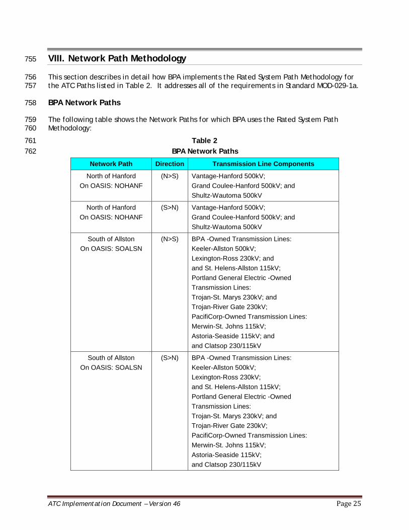
VIII. Network Path Methodology 755
This section describes in detail how BPA implements the Rated System Path Methodology for 756 the ATC Paths listed in Table 2. It addresses all of the requirements in Standard MOD-029-1a. 757
BPA Network Paths 758
The following table shows the Network Paths for which BPA uses the Rated System Path 759 Methodology: 760
Table 2 761 BPA Network Paths 762
Network Path Direction Transmission Line Components
North of Hanford On OASIS: NOHANF
(N>S) Vantage-Hanford 500kV; Grand Coulee-Hanford 500kV; and Shultz-Wautoma 500kV
North of Hanford On OASIS: NOHANF
(S>N) Vantage-Hanford 500kV; Grand Coulee-Hanford 500kV; and Shultz-Wautoma 500kV
South of Allston On OASIS: SOALSN
(N>S) BPA -Owned Transmission Lines: Keeler-Allston 500kV; Lexington-Ross 230kV; and and St. Helens-Allston 115kV; Portland General Electric -Owned Transmission Lines: Trojan-St. Marys 230kV; and Trojan-River Gate 230kV; PacifiCorp-Owned Transmission Lines: Merwin-St. Johns 115kV; Astoria-Seaside 115kV; and and Clatsop 230/115kV
South of Allston On OASIS: SOALSN
(S>N) BPA -Owned Transmission Lines: Keeler-Allston 500kV; Lexington-Ross 230kV; and St. Helens-Allston 115kV; Portland General Electric -Owned Transmission Lines: Trojan-St. Marys 230kV; and Trojan-River Gate 230kV; PacifiCorp-Owned Transmission Lines: Merwin-St. Johns 115kV; Astoria-Seaside 115kV; and Clatsop 230/115kV
ATC Implementation Document – Version 46 Page 26
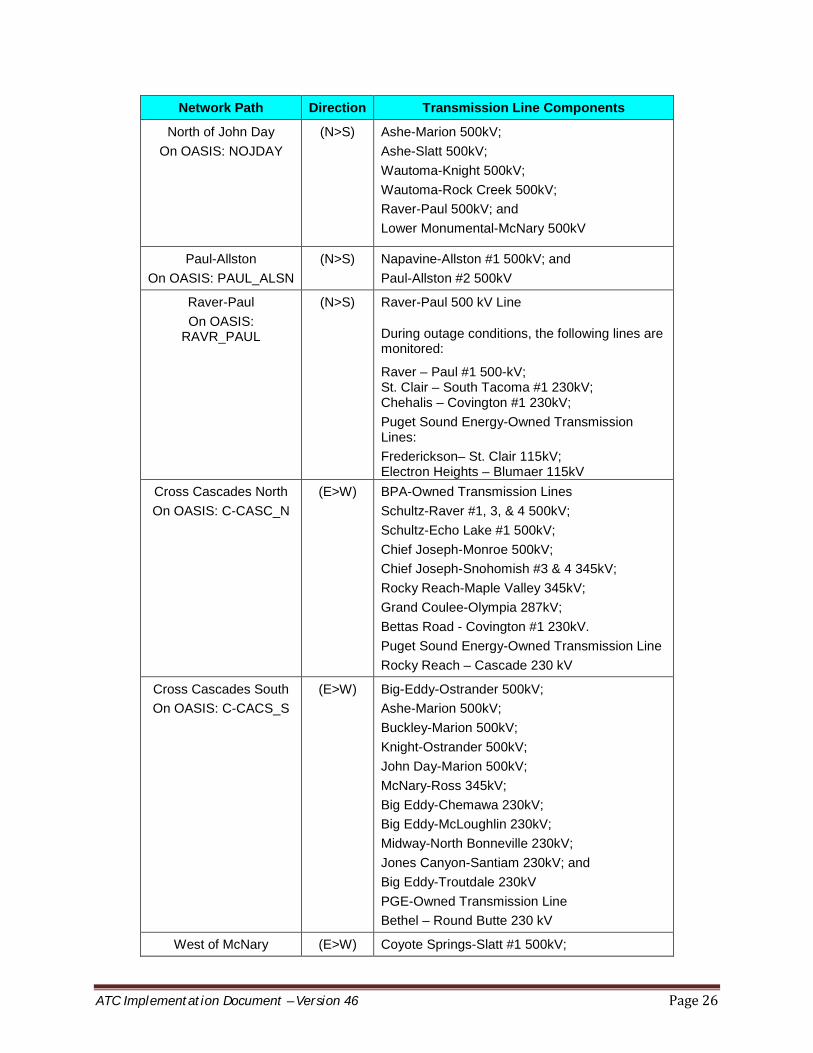
Network Path Direction Transmission Line Components
North of John Day On OASIS: NOJDAY
(N>S) Ashe-Marion 500kV; Ashe-Slatt 500kV; Wautoma-Knight 500kV; Wautoma-Rock Creek 500kV; Raver-Paul 500kV; and Lower Monumental-McNary 500kV
Paul-Allston On OASIS: PAUL_ALSN
(N>S) Napavine-Allston #1 500kV; and Paul-Allston #2 500kV
Raver-Paul On OASIS:
RAVR_PAUL
(N>S) Raver-Paul 500 kV Line
During outage conditions, the following lines are monitored:
Raver – Paul #1 500-kV; St. Clair – South Tacoma #1 230kV; Chehalis – Covington #1 230kV; Puget Sound Energy-Owned Transmission Lines: Frederickson– St. Clair 115kV; Electron Heights – Blumaer 115kV
Cross Cascades North On OASIS: C-CASC_N
(E>W) BPA-Owned Transmission Lines Schultz-Raver #1, 3, & 4 500kV; Schultz-Echo Lake #1 500kV; Chief Joseph-Monroe 500kV; Chief Joseph-Snohomish #3 & 4 345kV; Rocky Reach-Maple Valley 345kV; Grand Coulee-Olympia 287kV; Bettas Road - Covington #1 230kV. Puget Sound Energy-Owned Transmission Line Rocky Reach – Cascade 230 kV
Cross Cascades South On OASIS: C-CACS_S
(E>W) Big-Eddy-Ostrander 500kV; Ashe-Marion 500kV; Buckley-Marion 500kV; Knight-Ostrander 500kV; John Day-Marion 500kV; McNary-Ross 345kV; Big Eddy-Chemawa 230kV; Big Eddy-McLoughlin 230kV; Midway-North Bonneville 230kV; Jones Canyon-Santiam 230kV; and Big Eddy-Troutdale 230kV PGE-Owned Transmission Line Bethel – Round Butte 230 kV
West of McNary (E>W) Coyote Springs-Slatt #1 500kV;

ATC Implementation Document – Version 46 Page 27
Network Path Direction Transmission Line Components On OASIS: WOMCNY McNary-Ross #1 345kV;
Harvalum – Big Eddy #1 230 kV; Jones Canyon-Santiam #1 230kV; and McNary-John Day #2 500kV
West of Slatt On OASIS: WOSLATT
(E>W) Slatt-Buckley 500kV; and Slatt-John Day 500kV
West of John Day On OASIS: WOJD
(E>W) John Day – Big Eddy No. 1 500-kV line (metered at John Day); John Day – Big Eddy No. 2 500-kV line (metered at John Day); and John Day – Marion No. 1 500kV
South of Boundary On OASIS: SBNDRY
(N>S) Bell – Boundary #1 230kV; Bell – Boundary #3 230kV; Usk – Boundary #1 230kV; and Boundary 230/115kV Transformer #1
Columbia Injection On OASIS: CLMBIA
(N>S) Columbia-Grand Coulee #1 230-kV (metered at Columbia); Columbia-Grand Coulee #3 230-kV (metered at Columbia); Rocky Reach-Columbia #1 230-kV (metered at Columbia); Rocky Reach-Columbia #2 230-kV (metered at Columbia); Columbia-Valhalla #1 115-kV (metered at Columbia); and Columbia-Valhalla #2 115-kV (metered at Columbia)
Wanapum Injection On OASIS: WANAPM
(N>S) Midway-Vantage #1 230-kV; and Midway-Priest Rapids #3 230-kV
West of Lower Monumental
On OASIS: W_LOMO
(E>W) Ashe – Lower Monumental 500kV; Hanford – Lower Monumental 500kV; and McNary – Lower Monumental 500kV
North of Echo Lake On OASIS: N_ECOL
(S>N) Echo Lake – Monroe - SnoKing Tap #1 500kV; Echo Lake – Maple Valley #1 500 kV; Echo Lake – Maple Valley #2 500kV; and Covington – Maple Valley #2 230kV
South of Custer On OASIS: SCSTER
(N>S) Monroe - Custer #1 500kV; Monroe - Custer #2 500kV; Bellingham - Custer #1 230kV; and Murray - Custer #1 230kV Line
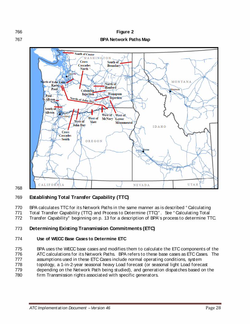
763 The following map shows the general geographic locations of the Network Paths listed in 764 Table 2, above: 765
ATC Implementation Document – Version 46 Page 28
Figure 2 766
BPA Network Paths Map 767
768
Establishing Total Transfer Capability (TTC) 769
BPA calculates TTC for its Network Paths in the same manner as is described “Calculating 770 Total Transfer Capability (TTC) and Process to Determine (TTC)”. See “Calculating Total 771 Transfer Capability” beginning on p. 13 for a description of BPA’s process to determine TTC. 772
Determining Existing Transmission Commitments (ETC) 773
Use of WECC Base Cases to Determine ETC 774
BPA uses the WECC base cases and modifies them to calculate the ETC components of the 775 ATC calculations for its Network Paths. BPA refers to these base cases as ETC Cases. The 776 assumptions used in these ETC Cases include normal operating conditions, system 777 topology, a 1-in-2-year seasonal heavy Load forecast (or seasonal light Load forecast 778 depending on the Network Path being studied), and generation dispatches based on the 779 firm Transmission rights associated with specific generators. 780

ATC Implementation Document – Version 46 Page 29
The WECC base cases include generation and Transmission expected to be in service or 781 available for service for the time period considered. The WECC base cases reflect input 782 from the WECC Significant Additions Report, which details retirements and new additions, 783 including those from other TSPs. BPA models new Transmission additions for its own 784 System in the WECC base cases as out of service until the energization date is within 0-16 785 days out, which is the time period BPA has determined to provide enough certainty about 786 the date of energization. 787
The WECC base cases that BPA uses meet the following criteria: 788
The WECC base cases include generator data in the power flow with generation 789 maximum (Pmax) reflecting the capability of the units. Under no circumstances is 790 Pmax greater than the maximum capability of the unit. BPA always uses the power 791 flow (Pgen) or optimal output of the generator at or within the Pmax and Pmin 792 Ratings for generators that are in service. Within each base case, the individual 793 Generator Owners are identified by numeric code. 794
The WECC base cases contain explicit modeling data and System topology for all 795 Facilities within the Peak RC Area, including AC Transmission Lines 115kV and above 796 and all DC Transmission Lines. Significant looped Transmission Lines rated at less 797 than 115 kV are also included in the WECC base cases. 798
The Peak RC Area covers the entire Western Interconnection and therefore does not 799 contain modeling data and System topology beyond the Peak RC Area. 800
BPA updates the relevant WECC base cases with equipment outages which are known and 801 mapped to the WECC base case, as well as newly-energized generation and Transmission 802 for ATC calculations at least once per day for intra-day, next day and days two through 803 30. Mapping of equipment to the WECC base case is contained in BPA’s Outage to Base 804 Case Mapping document. 805
BPA updates the relevant WECC base cases with equipment outages which are known and 806 mapped to the WECC base case, as well as newly-energized generation and Transmission 807 for ATC calculations at least once per month for months two through 13. Mapping of 808 equipment to the WECC base case is contained in BPA’s Outage to Base Case Mapping 809 document. 810
Outages in ETC Calculations 811
Generation outages known to BPA at the time BPA creates its ETC Cases are incorporated 812 into the generation dispatch assumptions in the base cases. See “Determining Base ETCFi” 813 beginning on p. 36 for a description of how BPA develops its ETC Cases. 814
BPA adjusts the WECC base cases to include Transmission outages for BPA’s area and all 815 adjacent TSP areas to calculate PTDFs, which are used in BPA’s ETC calculations. Note 816 that BPA has no executed coordination Agreements with other TSPs. (MOD-001 R3.6) 817
ATC Implementation Document – Version 46 Page 30
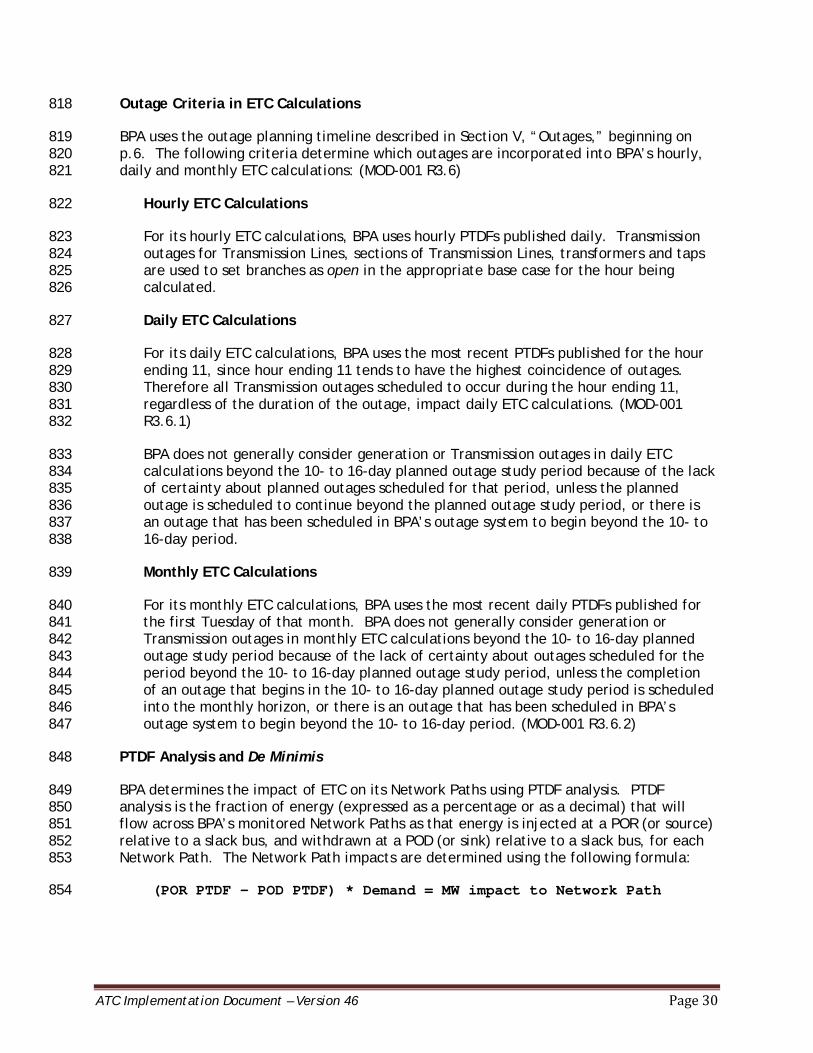
Outage Criteria in ETC Calculations 818
BPA uses the outage planning timeline described in Section V, “Outages,” beginning on 819 p.6. The following criteria determine which outages are incorporated into BPA’s hourly, 820 daily and monthly ETC calculations: (MOD-001 R3.6) 821
Hourly ETC Calculations 822
For its hourly ETC calculations, BPA uses hourly PTDFs published daily. Transmission 823 outages for Transmission Lines, sections of Transmission Lines, transformers and taps 824 are used to set branches as open in the appropriate base case for the hour being 825 calculated. 826
Daily ETC Calculations 827
For its daily ETC calculations, BPA uses the most recent PTDFs published for the hour 828 ending 11, since hour ending 11 tends to have the highest coincidence of outages. 829 Therefore all Transmission outages scheduled to occur during the hour ending 11, 830 regardless of the duration of the outage, impact daily ETC calculations. (MOD-001 831 R3.6.1) 832
BPA does not generally consider generation or Transmission outages in daily ETC 833 calculations beyond the 10- to 16-day planned outage study period because of the lack 834 of certainty about planned outages scheduled for that period, unless the planned 835 outage is scheduled to continue beyond the planned outage study period, or there is 836 an outage that has been scheduled in BPA’s outage system to begin beyond the 10- to 837 16-day period. 838
Monthly ETC Calculations 839
For its monthly ETC calculations, BPA uses the most recent daily PTDFs published for 840 the first Tuesday of that month. BPA does not generally consider generation or 841 Transmission outages in monthly ETC calculations beyond the 10- to 16-day planned 842 outage study period because of the lack of certainty about outages scheduled for the 843 period beyond the 10- to 16-day planned outage study period, unless the completion 844 of an outage that begins in the 10- to 16-day planned outage study period is scheduled 845 into the monthly horizon, or there is an outage that has been scheduled in BPA’s 846 outage system to begin beyond the 10- to 16-day period. (MOD-001 R3.6.2) 847
PTDF Analysis and De Minimis 848
BPA determines the impact of ETC on its Network Paths using PTDF analysis. PTDF 849 analysis is the fraction of energy (expressed as a percentage or as a decimal) that will 850 flow across BPA’s monitored Network Paths as that energy is injected at a POR (or source) 851 relative to a slack bus, and withdrawn at a POD (or sink) relative to a slack bus, for each 852 Network Path. The Network Path impacts are determined using the following formula: 853
(POR PTDF – POD PTDF) * Demand = MW impact to Network Path 854
ATC Implementation Document – Version 46 Page 31
If a reservation’s impact on a Network Path is less than or equal to 10 MW and the PTDF 855 difference is less than or equal to 10 percent of the reserved demand, the reservation is 856 deemed to have a de minimis impact on that Network Path. Ten percent is the 857 percentage used to curtail in the Western Interconnection-wide congestion management 858 procedure. When using reservations, BPA does not account for de minimis MW amounts in 859 its ETC calculations. 860
Source/POR and Sink/POD Identification and Mapping 861
In the ETC components of its Network Path ATC calculations, BPA accounts for source and 862 sink for Transmission Service through the following processes: 863
BPA maps the source/POR and sink/POD to the WECC base cases. In this mapping, BPA 864 has assigned network bus points that represent the primary interface for 865 Interconnection with specific generation projects, adjacent electrical Systems or 866 Load-serving entities and trading hubs. Some adjacent electrical Systems have 867 multiple Interconnection points deemed as PORs/sources or PODs/sinks. The mapping 868 of these points is published in the Transmission Service Contract Points list on BPA’s 869 OASIS homepage. 870
The source used in BPA’s Network Path ATC calculations of transactions within BPA’s 871 BAA is obtained from the POR field for Short-Term Reservations and the source field 872 for Long-Term Reservations, as shown on the TSR template in OASIS. The source used 873 in BPA’s Network Path ATC calculations of transactions for all adjacent TSPs is 874 obtained from the source field if a source is identified, or the POR field if only the 875 POR is identified. BPA represents the impact of Transmission Service using the source 876 or POR as follows: 877
• If the source or POR has been identified in the reservation and is discretely 878 modeled in the WECC base cases, BPA uses the discretely modeled point as 879 the source. 880
• In cases where the source or POR has been identified in the reservation and 881 the point can be mapped to an “equivalent” or “aggregate” representation in 882 the WECC base cases, BPA maps the source to the equivalence point in the 883 WECC base cases. These points are published in the Transmission Service 884 Contract Points List on BPA’s OASIS home page. 885
• If the source or POR has been identified in the reservation and the point 886 cannot be mapped to a discretely modeled point or an “equivalence” 887 representation in the WECC base cases, BPA uses the immediately adjacent 888 BA associated with the TSP from which the power is to be received as the 889 source. 890
• BPA requires a specified source or POR to be identified for all reservations. 891
The sink used in BPA’s Network Path ATC calculations of transactions within BPA’s 892 BAA is obtained from the POD field for Short-Term Reservations and the sink field for 893 Long-Term Reservations, as shown on the TSR template in OASIS. The sink used in 894 BPA’s Network Path ATC calculations of transactions for all adjacent TSPs is obtained 895 from the sink field if a sink is identified, or the POD field if only the POD is 896 identified. BPA represents the impact of Transmission Service using the sink or POD 897 as follows: 898

ATC Implementation Document – Version 46 Page 32
• If the sink or POD has been identified in the reservation and is discretely 899 modeled in the WECC base cases, BPA uses the discretely modeled point as 900 the sink or POD. 901
• In cases where the sink or POD has been identified in the reservation and the 902 point can be mapped to an “equivalent” or “aggregate” representation in the 903 WECC base case, BPA maps the sink or POD to the equivalence points in the 904 WECC base cases. These points are published in the Transmission Service 905 Contract Points list on BPA’s OASIS home page. 906
• If the sink or POD has been identified in the reservation and the point cannot 907 be mapped to a discretely modeled point or an “equivalence” representation 908 in the WECC base cases, BPA uses the immediately adjacent BA associated 909 with the TSP receiving the power as the sink or POD. 910
• BPA requires a specified sink or POD to be identified for all reservations. 911
BPA has grouped the FCRPS generators in BPA’s BAA and the Mid-Columbia generators based 912 on the primary interface between BPA and the generation projects. These groupings are 913 assigned weighted PTDFs that represent how the generators participate in the group. The 914 weighted PTDF for the FCRPS bus point is derived from a “weighted FCRTS” bus point. The 915 PTDF weighting for this point varies across different time periods. For the daily and monthly 916 calculations beyond 16 days out, BPA derives the weighting of the PTDF by applying the 917 generation dispatch determined in the ETC Cases. For the hourly and daily calculations for 918 the next hour out to day 16, the PTDF weighting is derived from generation forecasts of the 919 federal resources produced for that time period. BPA derives the PTDF weighting for the Mid-920 Columbia bus point by applying the generation dispatch determined in the ETC Cases. 921
BPA has also grouped the FCRPS generators in the Idaho Power Company BAA based on the 922 primary interface between Idaho Power Company and the generation projects. These 923 groupings are assigned a weighted PTDF that represent how the generators participate in the 924 group and are used to evaluate transactions within and between adjacent BAAs that do not 925 include BPAT. BPA derives the PTDF weighting for this point by applying the generation 926 dispatch determined in the ETC Cases. In the ETC Cases, these generators are modeled up to 927 the long-term firm Transmission rights associated with the generators. 928
BPA has grouped the generators in its adjacent BAAs based on the primary interface between 929 each BAA and the generation projects within that BAA (excluding some remote generators 930 that are scheduled via NERC e-Tag). These groupings are assigned weighted PTDFs that 931 represent how the generators participate in the group and are used to evaluate transactions 932 within and between adjacent BAAs that do not include BPAT. BPA derives the PTDF 933 weightings for these points from BAA-provided generation estimates or by applying the 934 generation dispatch determined in the ETC Cases if generation estimates are not available. In 935 the ETC Cases, these generators are modeled up to the long-term firm Transmission rights 936 associated with the generators. 937
Calculating Firm Transmission Service 938
Calculating Firm Existing Transmission Commitments (ETCFi) 939
When calculating the impact of ETCFi for all time periods for a Network Path, BPA uses the 940 following algorithm. (MOD-029 R5) 941
ATC Implementation Document – Version 46 Page 33
ETCFi = NITSFi + PTPFi + RORFi + GFFi + OSFi 942
Where: 943
NITSFi is the impact of firm Network Integration Transmission Service, including 944 impacts of generation to Load for BPA’s area. This impact is based on the Load 945 forecasts for Network Service Load for the time period being calculated and the 946 generation dispatch, which includes forecasted and designated network resources. 947
NITSFi also includes the impact of firm Network Integration Transmission Service, 948 including impacts of generation to Load for all of BPA’s adjacent TSP areas. This 949 impact is based on the Load forecasts for Network Service Load for the time period 950 being calculated and the generation dispatch, which includes designated network 951 resources. 952
PTPFi is the impact of confirmed firm Point-to-Point Transmission Service expected to 953 be scheduled in BPA’s area. 954
PTPFi also includes the impact of confirmed Point-to-Point Firm Transmission Service 955 expected to be scheduled for all of BPA’s adjacent TSP areas. 956
There are no reservations using Transmission Service from multiple TSPs, and 957 therefore no duplicate impacts, since reservations source and sink within the same 958 TSP’s area. A separate reservation is required to acquire Transmission Service over 959 another TSP’s area. When using schedules, BPA includes all schedules for all of its 960 adjacent TSP areas, regardless of their PTDF analysis impact on BPA’s Network Paths. 961
RORFi is the impact of roll-over rights for Firm Transmission Service contracts for BPA’s 962 area. BPA assumes that all of its Transmission Service Agreements eligible to roll-over 963 in the future will be rolled over. Therefore the impact of the roll-over rights for 964 Transmission contracts in BPA’s area is calculated based on the NITSFi, GFFi and PTPFi 965 obligations that are eligible for roll-over rights. For reservations that are eligible for 966 roll-over rights, BPA creates a reservation in the form of a Transmission Service 967 Number (TSN), with a Demand equal to the amount eligible to roll-over. BPA models 968 these reservations in its ETC Cases. For TSNs that were not modeled in the ETC Cases, 969 BPA derives the Network Path impacts of these reservations using PTDF analysis. If 970 BPA’s customers choose not to exercise their roll-over rights by the required deadline, 971 BPA no longer holds out capacity for roll-over rights for that customer. 972
RORFi also includes roll-over rights for Firm Transmission Service contracts for all of 973 BPA’s adjacent TSPs. BPA assumes that all Long-Term Reservations for all of BPA’s 974 adjacent TSP areas will be rolled over. 975
GFFi is the impact of grandfathered firm obligations expected to be scheduled or 976 expected to flow for BPA’s area. 977
GFFi also includes the impact of grandfathered firm obligations expected to be 978 scheduled or expected to flow for all of BPA’s adjacent TSP areas. 979
OSFi is the impact of other firm services. 980

ATC Implementation Document – Version 46 Page 34
BPA has no other firm services beyond those specified above. Therefore BPA sets OSFi 981 at zero for all of its Network Paths for all time periods. 982
BPA does not have coordination Agreements with other TSPs. 983
As a result, BPA calculates ETCFi for all of its Network Paths for all time periods as follows: 984
ETCFi = NITSFi + PTPFi + GFFi + RORFi 985
When using reservations, BPA further divides the ETCFi described previously into two 986 components: the base ETCFi values determined using the ETC Cases, and interim ETCFi 987 impacts determined using PTDF analysis. These components are added together to calculate 988 a final ETCFi. 989
As described in “PTDF Analysis and De Minimis” on p.32, de minimis MW amounts of 990 reservations that were not modeled in the ETC Cases are not accounted for when calculating 991 ETCFi using reservations. However, all schedules are accounted for in ETCFi regardless of their 992 PTDF analysis impact on BPA’s Network Paths when calculating ETCFi using schedules. 993
While BPA includes all of the components described above in ETCFi, BPA accounts for NITSFi, 994 GFFi, PTPFi and RORFi in its Network Path ATC calculations using different variables. For 995 descriptions of the variables used see p. 35. 996
Determining Base ETCFi 997
As indicated in “Use of the WECC Base Cases to determine ETC” beginning on p.30, BPA 998 creates heavy load ETC Cases for the months of January, May, and August and light load ETC 999 cases for the month of January as representative seasons to calculate base ETCFi values. 1000 BPA’s ETC Cases are produced using a power flow model that computes how much power will 1001 flow over each Network Path for the assumed Load and generation levels for each season. 1002 Counterflows are inherently modeled in these base cases. 1003
In ETC Cases, BPA models all of its own NITSFi, GFFi and PTPFi Long-Term Reservations, as well as 1004 those of its adjacent TSPs, active at the time the ETC Cases are produced. 1005
To model the impact of PTPFi long-term reservations for all of its adjacent TSPs, BPA queries a 1006 list of PTPFi long-term reservations from the OASIS of its adjacent TSPs. To model the impact 1007 of GFFi and NITSFi long-term obligations for all of BPA’s adjacent TSPs, BPA contacts its 1008 adjacent TSPs and requests a list of their GFFi obligations and a list of their NITSFi with a list 1009 of designated network resources with the MW amounts designated to serve Network Service 1010 and Native Load. 1011
BPA models the NITSFi, GFFi and PTPFi Long-Term obligations of all of its adjacent TSPs to the 1012 extent that there are sufficient firm Transmission rights on BPA’s or its adjacent TSPs’ 1013 Transmission Systems to serve the Load. 1014
BPA uses the following assumptions to create ETC Cases for its ETCFi calculations: 1015
System topology: Normal operating conditions are used. 1016
ATC Implementation Document – Version 46 Page 35
Load: BPA uses Loads contained in the WECC base cases for the time periods being 1017 studied, along with any updates to those Loads BPA may have made after the WECC 1018 base cases were received from WECC. 1019
• NITSFi: BPA assumes a 1-in-2 year seasonal heavy or light Load forecast, depending 1020 on the Network Path being studied. 1021
• PTPFi and GFFi: For the PTPFi and GFFi Long-Term Reservations modeled in the ETC 1022 Cases, BPA assumes the lesser of the 1-in-2 year non-coincidental seasonal peak 1023 Load forecast or firm rights to deliver power to the Load. 1024
Generation: BPA does not use the generation assumptions contained in the WECC 1025 base cases. Instead, BPA uses the following generation assumptions: 1026
FCRPS: For the FCRPS resources serving NITSFi, PTPFi, and GFFi Long-Term 1027 Reservations, generation levels are set using a multiple-step process. For all 1028 seasons, BPA uses the following process: 1029
ATC Implementation Document – Version 46 Page 36
• The Columbia Generating Station is assumed to be on-line at full Load in the 1030 ETC cases.Generation levels at the Libby, Hungry Horse, Dworshak, and Albeni 1031 Falls projects are set based on the requirements set forth in the 2000 Biological 1032 Opinion. In addition, the generation levels at the Willamette Valley projects5 1033 are set at the minimum levels seen by season during Calendar Year 1034 2001.Nameplate Adjusted Method: When creating heavy load ETC Cases, 1035 generation levels for all other federal hydro projects6 are set by first 1036 determining the nameplate for each project and then adjusting such 1037 nameplates by outages forecasted for the particular plants. Next in the month 1038 of August, the Lower Snake plants (Lower Granite, Lower Monumental, Little 1039 Goose, and Ice Harbor) are capped at the observed project outflow over the 1040 past ten Augusts. Then multiple generation scenarios are modelled by stressing 1041 one of three different “zones” of Federal hydro resources to the nameplate 1042 adjusted generation levels described above and scales the generation at the 1043 remaining Federal hydro projects to match the sum of the demands for all 1044 contracts that call out non-specific Federal hydroelectric projects as PORs 1045 after adjusting these demands for the portion served by Columbia Generating 1046 Station, Libby, Hungry Horse, Dworshak, Albeni Falls, and the Willamette 1047 Valley projects. The Federal PTP demands at each project are then added to 1048 this result to obtain the final assumed generation level for each Federal hydro 1049 project. This overall method for modeling the federal resources is referred to 1050 as the “Nameplate Adjusted Method.” 1051
Non-Federal Thermal Generators: Non-federal thermal generators associated with 1052 PTPFi, GFFi and NITSFi Transmission Service for BPA’s area and all adjacent TSP areas 1053 are set at up to the contract Demand. 1054
Wind Generators: 1055
• PTPFi: Wind generators associated with PTPFi Long-Term Reservations are set 1056 at the greater of the following: 1057 o Modeled on at 100 percent of the contract demand for the wind 1058
generator; or 1059 o Modeled off and replaced by the “Balancing Logic Method”. 1060
5 Willamette Valley projects include: Big Cliff, Cougar, Detroit, Dexter, Foster, Green Peter, Hills Creek, Lookout Point, and Lost Creek.
6 Federal hydro projects include: Grand Coulee, Chief Joseph, Lower Granite, Lower Monumental, Little Goose, Ice Harbor, McNary, John Day, The Dalles, Bonneville.
6 Willamette Valley projects include: Big Cliff, Cougar, Detroit, Dexter, Foster, Green Peter, Hills Creek, Lookout Point, Lost Creek.

ATC Implementation Document – Version 46 Page 37
• NITSFi: The Network Path impacts of wind generators identified as designated 1061 network resources in NITSFi contracts or in the NT Resources Memorandum of 1062 Agreement in BPA’s area are determined on a Network Path-by-Network Path 1063 basis and set at the greater of the following: 1064 o The wind generators modeled on at the designated amount of the wind 1065
generators; or, 1066 o The wind generators modeled off and replaced by increasing the FCRPS 1067
generation level by the designated amount of the wind generators using 1068 the “Nameplate Adjusted Method” for all seasons described above. 1069
Wind generators designated as network resources in NITSFi contracts for all 1070 adjacent TSPs are modeled up to the designated amount. 1071
• GFFi: BPA and all of BPA’s adjacent TSPs have no GFFi contracts for wind 1072 generators. 1073
Behind the Meter Generators: Non-federal resources that do not require 1074 Transmission Service over the FCRTS and that are behind the meter are set up to 1075 levels used in BPA’s process for power system planning studies. 1076
Mid-Columbia Hydro Projects: Generation levels at the non-federal Mid-Columbia 1077 hydro projects are set up to 90 percent of their historical output by season. 1078
When creating heavy load ETC Cases, if there is more generation than load plus 1079 committed exports in the base case, BPA reduces all excess generation prorata, except for 1080 the stressed FCRPS zone see below, using the “Balancing Logic Method” for all seasons; 1081 the exports modeled on the COI and Pacific DC Intertie in the base case are reduced to 1082 match BPA’s obligation for firm export. The generation reduction is done to bring 1083 generation and load into balance in order to solve the power flow model. 1084
When creating light load ETC Cases, if there is more generation than Load in the base 1085 case, BPA reduces excess generation using a merit order sequence of tiered generation 1086 groups that are assumed to be re-dispatched based on age, heat rate, and past operation. 1087
Sensitivity Studies 1088
In calculating its base ETCFi values, BPA runs ETC Case Scenarios for three different 1089 sensitivities: the Canadian Entitlement Return (CER) obligation modeled on or off, wind 1090 resources designated to serve PTPFi and NITSFi on or off, and stressing the three different 1091 zones of the FCRPS. 1092
For the FCRPS scenarios, the three “zones” that are stressed individually in the scenarios 1093 are made up of the following projects: (i) Upper Columbia zone includes Grand Coulee 1094 and Chief Joseph; (ii) Lower Snake zone includes Lower Monumental, Lower Granite, Little 1095 Goose, and Ice Harbor; and (iii) Lower Columbia zone includes McNary, John Day, The 1096 Dalles and Bonneville. 1097
For the CER Scenarios, BPA models the FCRPS generators delivering or not delivering 1098 energy to Canada in the amount specified in the Canadian Entitlement Agreement. 1099
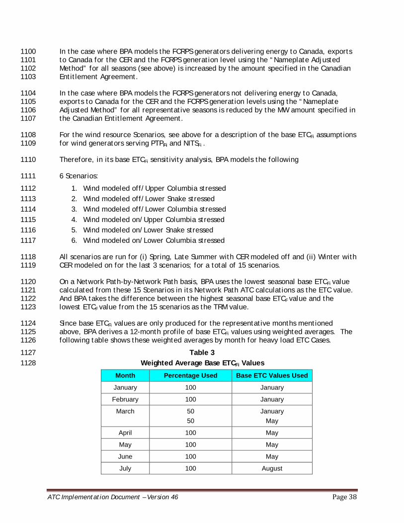
ATC Implementation Document – Version 46 Page 38
In the case where BPA models the FCRPS generators delivering energy to Canada, exports 1100 to Canada for the CER and the FCRPS generation level using the “Nameplate Adjusted 1101 Method” for all seasons (see above) is increased by the amount specified in the Canadian 1102 Entitlement Agreement. 1103
In the case where BPA models the FCRPS generators not delivering energy to Canada, 1104 exports to Canada for the CER and the FCRPS generation levels using the “Nameplate 1105 Adjusted Method” for all representative seasons is reduced by the MW amount specified in 1106 the Canadian Entitlement Agreement. 1107
For the wind resource Scenarios, see above for a description of the base ETCFi assumptions 1108 for wind generators serving PTPFi and NITSFi . 1109
Therefore, in its base ETCFi sensitivity analysis, BPA models the following 1110
6 Scenarios: 1111
1. Wind modeled off/Upper Columbia stressed 1112 2. Wind modeled off/Lower Snake stressed 1113 3. Wind modeled off/Lower Columbia stressed 1114 4. Wind modeled on/Upper Columbia stressed 1115 5. Wind modeled on/Lower Snake stressed 1116 6. Wind modeled on/Lower Columbia stressed 1117
All scenarios are run for (i) Spring, Late Summer with CER modeled off and (ii) Winter with 1118 CER modeled on for the last 3 scenarios; for a total of 15 scenarios. 1119
On a Network Path-by-Network Path basis, BPA uses the lowest seasonal base ETCFi value 1120 calculated from these 15 Scenarios in its Network Path ATC calculations as the ETC value. 1121 And BPA takes the difference between the highest seasonal base ETCF value and the 1122 lowest ETCF value from the 15 scenarios as the TRM value. 1123
Since base ETCFi values are only produced for the representative months mentioned 1124 above, BPA derives a 12-month profile of base ETCFi values using weighted averages. The 1125 following table shows these weighted averages by month for heavy load ETC Cases. 1126
Table 3 1127 Weighted Average Base ETCFi Values 1128
Month Percentage Used Base ETC Values Used
January 100 January
February 100 January
March 50 50
January May
April 100 May
May 100 May
June 100 May
July 100 August
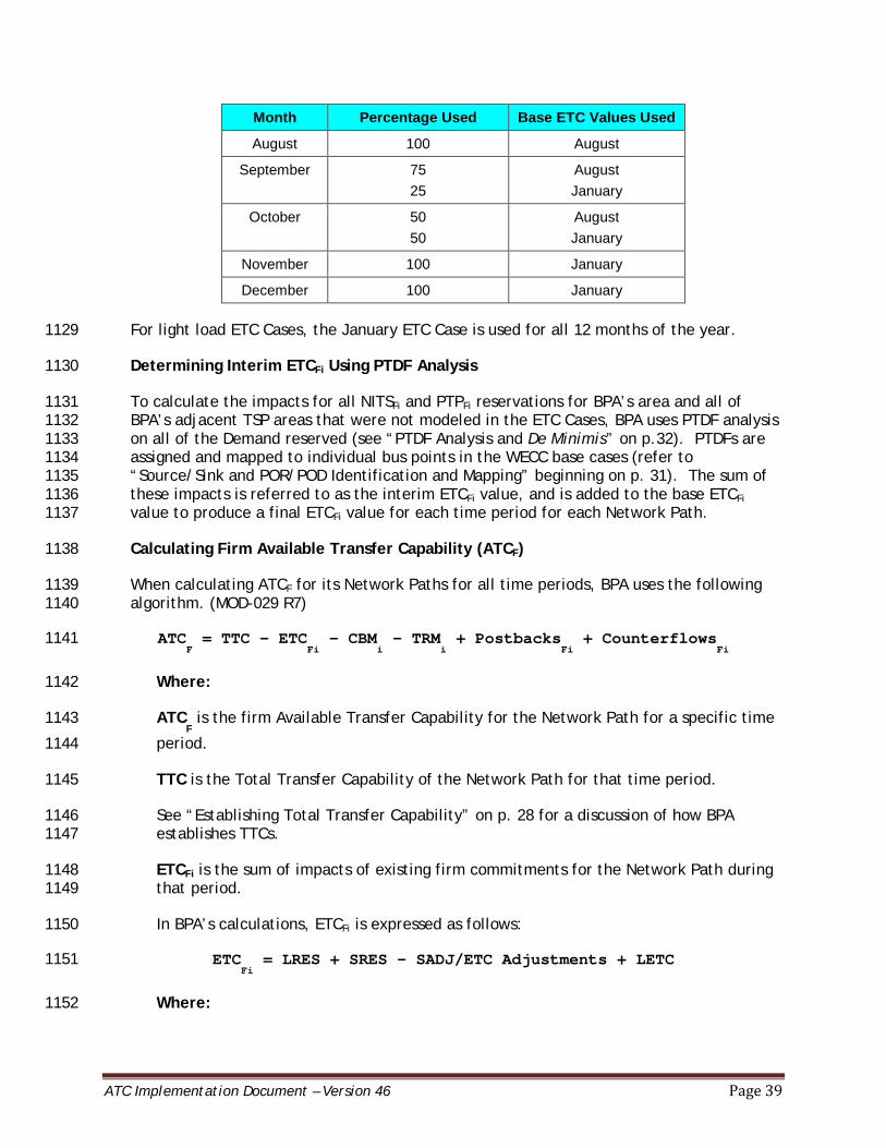
ATC Implementation Document – Version 46 Page 39
Month Percentage Used Base ETC Values Used
August 100 August
September 75 25
August January
October 50 50
August January
November 100 January
December 100 January
For light load ETC Cases, the January ETC Case is used for all 12 months of the year. 1129
Determining Interim ETCFi Using PTDF Analysis 1130
To calculate the impacts for all NITSFi and PTPFi reservations for BPA’s area and all of 1131 BPA’s adjacent TSP areas that were not modeled in the ETC Cases, BPA uses PTDF analysis 1132 on all of the Demand reserved (see “PTDF Analysis and De Minimis” on p.32). PTDFs are 1133 assigned and mapped to individual bus points in the WECC base cases (refer to 1134 “Source/Sink and POR/POD Identification and Mapping” beginning on p. 31). The sum of 1135 these impacts is referred to as the interim ETCFi value, and is added to the base ETCFi 1136 value to produce a final ETCFi value for each time period for each Network Path. 1137
Calculating Firm Available Transfer Capability (ATCF) 1138
When calculating ATCF for its Network Paths for all time periods, BPA uses the following 1139 algorithm. (MOD-029 R7) 1140
ATCF = TTC - ETC
Fi - CBM
i - TRM
i + Postbacks
Fi + Counterflows
Fi 1141
Where: 1142
ATCF is the firm Available Transfer Capability for the Network Path for a specific time 1143
period. 1144
TTC is the Total Transfer Capability of the Network Path for that time period. 1145
See “Establishing Total Transfer Capability” on p. 28 for a discussion of how BPA 1146 establishes TTCs. 1147
ETCFi is the sum of impacts of existing firm commitments for the Network Path during 1148 that period. 1149
In BPA’s calculations, ETCFi is expressed as follows: 1150
ETCFi = LRES + SRES - SADJ/ETC Adjustments + LETC 1151
Where: 1152

ATC Implementation Document – Version 46 Page 40
LRES is the sum of the positive impacts of PTPFi, GFFi, RORFi and NITSFi Long-Term 1153 Reservations for BPA’s area, plus the sum of the positive impacts of PTPFi, GFFi, RORFi 1154 and NITSFi Long-Term Reservations for all of BPA’s adjacent TSP areas, filtered to 1155 reduce or eliminate duplicate impacts from transactions that were already included in 1156 the ETC Case or that impact another Transmission Service’s Providers share of 1157 Transfer Capability. 1158
SRES is the sum of the positive impacts of PTPFi Short-Term Reservations for BPA’s 1159 area, plus the sum of the positive impacts of PTPFi Short-Term Reservations for all of 1160 BPA’s adjacent TSP areas, filtered to reduce or eliminate duplicate impacts from 1161 transactions that were already included in the ETC Case or that impact another 1162 Transmission Service’s Providers share of Transfer Capability. 1163
SADJ/ETC Adjustments is the variable used to make adjustments to ETCFi not 1164 captured in LRES or SRES. One such adjustment is applied to allow BPA to conduct 1165 deferral competitions, as required in Section 17.7 of BPA’s OATT. When a deferral 1166 reservation is confirmed, BPA applies an ETC adjustment to hold out Transfer 1167 Capability for the time period deferred, starting at the latter of five months out or the 1168 service commencement date of the original reservation, to allow for a competition. 1169 At four months out, if no competition is identified, the ETC adjustment is modified to 1170 add back Transfer Capability for the fourth month out. 1171
BPA uses SADJ adjustments to include a commercial uncertainty margin, which is the 1172 difference between the highest ETCFi value and lowest ETCFi value from all seasonal 1173 scenarios. At four months out, the adjustment is modified to add non-firm capability 1174 for the fourth month out. Additionally, BPA uses SADJ adjustments to represent the 1175 CER Off/On scenarios for the Cross Cascades North, Cross Cascades South, and North 1176 of Echo Lake flowgates. This is a PTDF adjustment that will apply to the months March 1177 through October (applied to the May, and August Base Case values to account for 1178 ETCFi. 1179
BPA also uses SADJ/ETC adjustments to ensure accurate accounting of ETCFi. These 1180 adjustments may be performed to account for situations such as data modeling 1181 corrections, and will be noted in the descriptions of the adjustments. LETC is the 1182 variable used to ensure that the amount of PTPFi and GFFi capacity BPA sets aside in 1183 the LRES variable does not exceed the total PTPFi and GFFi capacity specified in the 1184 contracts. Since BPA has PTP and GF contracts that give customers the right to 1185 schedule the capacity reserved between multiple PORs and PODs, this adjustment is 1186 necessary to ensure that ETCFi is not inflated. 1187
LETC is also used to adjust the LRES variable to match the base ETC values BPA 1188 calculates when BPA develops its ETC Cases. This adjustment is derived by comparing 1189 two values: a) the impacts of the confirmed PTPFi, GFFi and NITSFi Long-Term 1190 Reservations derived from the ETC Cases and b) the impacts of the same reservations 1191 calculated using PTDF Analysis for each Network Path. The adjustment for each 1192 Network Path is equal to the difference of these two values. Conditional firm 1193 reservations are not included in the ETC Cases and therefore are also not included in 1194 this comparison. 1195
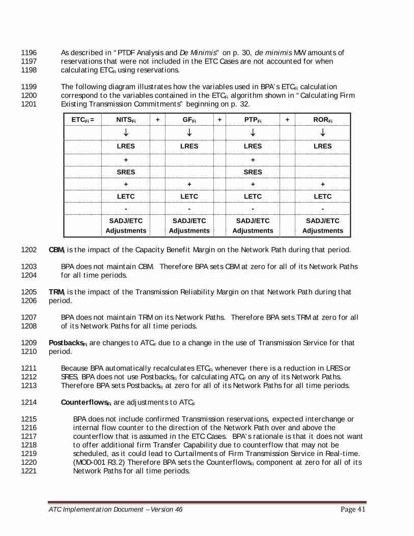
ATC Implementation Document – Version 46 Page 41
As described in “PTDF Analysis and De Minimis” on p. 30, de minimis MW amounts of 1196 reservations that were not included in the ETC Cases are not accounted for when 1197 calculating ETCFi using reservations. 1198
The following diagram illustrates how the variables used in BPA’s ETCFi calculation 1199 correspond to the variables contained in the ETCFi algorithm shown in “Calculating Firm 1200 Existing Transmission Commitments” beginning on p. 32. 1201
ETCFi = NITSFi + GFFi + PTPFi + RORFi
↓ ↓ ↓ ↓
LRES LRES LRES LRES
+ +
SRES SRES
+ + + +
LETC LETC LETC LETC
- - - -
SADJ/ETC Adjustments
SADJ/ETC Adjustments
SADJ/ETC Adjustments
SADJ/ETC Adjustments
CBMi is the impact of the Capacity Benefit Margin on the Network Path during that period. 1202
BPA does not maintain CBM. Therefore BPA sets CBM at zero for all of its Network Paths 1203 for all time periods. 1204
TRMi is the impact of the Transmission Reliability Margin on that Network Path during that 1205 period. 1206
BPA does not maintain TRM on its Network Paths. Therefore BPA sets TRM at zero for all 1207 of its Network Paths for all time periods. 1208
PostbacksFi are changes to ATCF due to a change in the use of Transmission Service for that 1209 period. 1210
Because BPA automatically recalculates ETCFi whenever there is a reduction in LRES or 1211 SRES, BPA does not use PostbacksFi for calculating ATCF on any of its Network Paths. 1212 Therefore BPA sets PostbacksFi at zero for all of its Network Paths for all time periods. 1213
CounterflowsFi are adjustments to ATCF 1214
BPA does not include confirmed Transmission reservations, expected interchange or 1215 internal flow counter to the direction of the Network Path over and above the 1216 counterflow that is assumed in the ETC Cases. BPA’s rationale is that it does not want 1217 to offer additional firm Transfer Capability due to counterflow that may not be 1218 scheduled, as it could lead to Curtailments of Firm Transmission Service in Real-time. 1219 (MOD-001 R3.2) Therefore BPA sets the CounterflowsFi component at zero for all of its 1220 Network Paths for all time periods. 1221
ATC Implementation Document – Version 46 Page 42
As a result, BPA calculates ATCF for its Network Paths for all time periods as follows: 1222
ATCF = TTC - ETC
Fi 1223
As described in “Determining Base ETCFi” on p. 33, counterflows are modeled in the ETC 1224 Cases. In some seasons, the amount of counterflows on particular Network Paths results in a 1225 negative ETCFi value, which, when subtracted from TTC, results in ATCF greater than TTC. 1226
Calculating Non-Firm Transmission Service 1227
BPA sells six non-firm Transmission products. These products are: 1228
1. NITSNF6i. This is a non-firm Transmission product available only to Transmission 1229 Customers with NITS Agreements. It is the highest quality of Non-Firm 1230 Transmission Service in that it is the last Non-Firm Transmission Service that would 1231 be Curtailed, if necessary. 1232
2. PTPNF5i. This is a non-firm Transmission product available only to Transmission 1233 Customers with PTP Agreements. PTPNF5i is the fifth Non-Firm Transmission Service 1234 that would be Curtailed, if necessary. 1235
3. PTPNF4i. This is a non-firm Transmission product available only to Transmission 1236 Customers with PTP Agreements. PTPNF4i is the fourth Non-Firm Transmission 1237 Service that would be Curtailed, if necessary. 1238
4. PTPNF3i. This is a non-firm Transmission product available only to Transmission 1239 Customers with PTP Agreements. PTPNF3i is the third Non-Firm Transmission 1240 Service that would be Curtailed, if necessary. 1241
5. PTPNF2i. This is a non-firm Transmission product available only to Transmission 1242 Customers with PTP Agreements. PTPNF2i is the second Non-Firm Transmission 1243 Service that would be Curtailed, if necessary. 1244
6. PTPNF1i. This is a non-firm Transmission product available only to Transmission 1245 Customers with PTP Agreements. PTPNF1i is the first Non-Firm Transmission Service 1246 that would be Curtailed, if necessary (i.e., this Transmission Service has the 1247 highest likelihood of being Curtailed). 1248
BPA calculates ETCNFi and ATCNF for each of these products. 1249
Calculating Non-Firm Existing Transmission Commitments (ETCNFi) 1250
When calculating ETCNFi for all time periods for a Network Path, BPA sums the positive 1251 impacts using PTDF analysis (see “PTDF Analysis and De Minimis” on p. 30 for further 1252 details). (MOD-029 R6) 1253
ETCNFi = PTPNFi + GFNFi + NITSNFi + OSNFi 1254
Where: 1255

ATC Implementation Document – Version 46 Page 43
PTPNFi is the impact of all confirmed non-firm Point-to-Point Transmission Service 1256 expected to be scheduled for BPA’s area. In BPA’s calculations, the PTPNFi component 1257 includes PTPNF5i, PTPNF4i, PTPNF3i, PTPNF2i and PTPNF1i. 1258
PTPNFi also includes the impacts of any confirmed non-firm PTP Transmission Service 1259 expected to be scheduled for all of BPA’s adjacent TSP areas. There are no 1260 reservations using Transmission Service from multiple TSPs, and therefore no duplicate 1261 impacts, since reservations source and sink within the same TSP’s area. A separate 1262 reservation is required to acquire Transmission Service over another TSP’s area. Note 1263 that BPA does not have coordination Agreements with other TSPs. 1264
GFNFi is the impact of all grandfathered non-firm obligations expected to be scheduled 1265 or expected to flow for BPA’s area. BPA does not have any grandfathered non-firm 1266 Transmission Service obligations. 1267
GFNFi also includes the impacts of any grandfathered non-firm obligations expected to 1268 be scheduled or expected to flow for all of BPA’s adjacent TSPs. None of BPA’s 1269 adjacent TSPs have any grandfathered Non-Firm Transmission Service obligations. 1270
Therefore BPA sets GFNFi at zero for all of its Network Paths for all time periods. 1271
NITSNFi is the non-firm Network Integration Transmission Service serving Load within 1272 BPA’s area (i.e., secondary service), to include losses, and Load growth not otherwise 1273 included in TRM or CBM. 1274
In BPA’s calculations, this is NITSNF6i. BPA’s NITSNF6i calculations do not include losses 1275 or Load growth, since losses and Load growth are already set aside as firm capacity in 1276 NITSFi. 1277
NITSNFi also includes non-firm Network Integration Transmission Service (i.e., secondary 1278 service) for all of BPA’s adjacent TSP areas. There are no transactions using 1279 Transmission Service from multiple TSPs, and therefore no duplicate impacts, since 1280 transactions source and sink within the same TSP’s area. A separate reservation is 1281 required to acquire Transmission Service over another TSP’s area. Note that BPA does 1282 not have coordination Agreements with other TSPs. 1283
OSNFi is the impact of other non-firm services. 1284
BPA has no other non-firm services beyond those specified above. Therefore BPA sets 1285 OSNFi at zero for all of its Network Paths for all time periods. 1286
As a result, BPA calculates ETCNFi for all time periods for its Network Paths as follows: 1287
ETCNFi = PTPNFi + NITSNFi 1288
As described in “PTDF Analysis and De Minimis” on p. 30, BPA does not account for de 1289 minimis MW amounts when calculating ETCNFi using reservations. However, all schedules 1290 are accounted for in ETCNFi regardless of their PTDF analysis impact on BPA’s Network 1291 Paths when calculating ETCNFi using schedules. 1292
ATC Implementation Document – Version 46 Page 44
While BPA includes all of the components described above in ETCNFi, BPA accounts for 1293 PTPNFi and NITSNFi in its Network Path ATC calculations using different variables. For a 1294 description of the variables used see p. 47. 1295
Calculating Non-Firm Available Transfer Capability (ATCNF) 1296
BPA uses different algorithms to calculate ATCNF, ETCFi and ETCNFi for two time horizons 1297 for all of its Network Paths: Real-time and beyond Real-time. The Real-time horizon 1298 begins at 10 p.m. on the pre-schedule day for the 24 hours in the next day. The ETCFi and 1299 ETCNFi for the Real-Time horizon are calculated using schedules and reservations that have 1300 not yet been scheduled. The time horizon beyond Real-time includes hourly for the hours 1301 after those included in the Real-time period as well as daily and monthly calculations. 1302 The ETCFi and ETCNFi for the time horizon beyond Real-time is calculated using 1303 reservations. 1304
BPA calculates ETCNFi and ATCNF for the six non-firm Transmission products (described 1305 beginning on p. 42) associated with NERC Curtailment priorities as follows: 1306
1. ATCNF6: ATCNF6 is calculated for the NITSNF6i product. ETCNFi in this equation only 1307 includes NITSNF6i. 1308
2. ATCNF5: ATCNF5 is calculated for the PTPNF5i product. ETCNFi in this equation 1309 includes NITSNF6i and PTPNF5i. 1310
3. ATCNF4: ATCNF4 is calculated for the PTPNF4i product. ETCNFi in this equation 1311 includes NITSNF6i, PTPNF5i and PTPNF4i. 1312
4. ATCNF3: ATCNF3 is calculated for the PTPNF3i product. ETCNFi in this equation 1313 includes NITSNF6i, PTPNF5i, PTPNF4i, and PTPNF3i. 1314
5. ATCNF2: ATCNF2 is calculated for the PTPNF2i product. ETCNFi in this equation 1315 includes NITSNF6i, PTPNF5i, PTPNF4i, PTPNF3i and PTPNF2i. 1316
6. ATCNF1: ATCNF1 is calculated for the PTPNF1i product. ETCNFi in this equation 1317 includes NITSNF6i, PTPNF5i, PTPNF4i, and PTPNF3i, PTPNF2i and PTPNF1i. 1318
BPA calculates ETCNFi and ATCNF for each of these products for each time period. 1319
When calculating ATCNF for its Network Paths for the two time horizons described above, 1320 BPA uses the following algorithm. (MOD-029 R8) 1321
ATCNF = TTC – ETCFi – ETCNFi – CBMSi -TRMUi + PostbacksNFi + CounterflowNFi 1322
Where: 1323
ATCNF is the non-firm Available Transfer Capability for the Network Path for that 1324
period. 1325
BPA calculates six ATCNF values (as described above), one for each of the six non-1326 firm Transmission products. 1327
ATC Implementation Document – Version 46 Page 45
TTC is the Total Transfer Capability of the Network Path for that period. 1328
See “Establishing Total Transfer Capability” on p. 28, for a description of how BPA 1329 establishes TTC. 1330
ETCFi is the sum of the impacts of existing firm Transmission commitments for the 1331 Network Path during that period. 1332
BPA uses different algorithms to calculate ETCFi for all of its Network Paths for the 1333 time horizon beyond Real-time and the Real-time horizon. 1334
ETCFi for the Time Horizon Beyond Real-Time 1335
For Network Path ATCNF calculations for the time horizon beyond Real-time, ETCFi is 1336 expressed as follows: 1337
ETCFi = LRES + SRES - SADJ/ETC Adjustments + LETC 1338
Where: 1339
LRES is the sum of the positive impacts of PTPFi, GFFi, RORFi and NITSFi Long-Term 1340 Reservations for BPA’s area, plus the sum of the positive impacts of PTPFi, GFFi, RORFi 1341 and NITSFi Long-Term Reservations for all of BPA’s adjacent TSP areas, filtered to 1342 reduce or eliminate duplicate impacts from transactions that were already included in 1343 the ETC base case or that impact another Transmission Service’s Providers share of 1344 Transfer Capability. 1345
SRES is the sum of the positive impacts of PTPFi Short-Term Reservations for BPA’s 1346 area, plus the sum of the positive impacts of PTPFi Short-Term Reservations for all of 1347 BPA’s adjacent TSP areas, filtered to reduce or eliminate duplicate impacts from 1348 transactions that were already included in the ETC Case or that impact another 1349 Transmission Service’s Providers share of Transfer Capability. 1350
SADJ/ETC Adjustments is the variable used to make adjustments to ETCFi not 1351 captured in LRES or SRES. One such adjustment is applied to allow BPA to conduct 1352 deferral competitions, as required in Section 17.7 of BPA’s OATT. When a deferral 1353 reservation is confirmed, BPA applies an ETC adjustment to hold out Transfer 1354 Capability for the time period deferred, starting at the latter of five months out or the 1355 service commencement date of the original reservation, to allow for a competition. 1356 At four months out, if no competition is identified, the ETC adjustment is modified to 1357 add back Transfer Capability for the fourth month out. 1358
BPA uses SADJ adjustments to include a commercial uncertainty margin, which is the 1359 difference between the highest ETCFi value and lowest ETCFi value from all seasonal 1360 scenarios. At four months out, the adjustment is modified to add non-firm capability 1361 for the fourth month out. Additionally, BPA uses SADJ adjustments to represent the 1362 CER Off/On scenarios for the Cross Cascades North, Cross Cascades South, and North 1363 of Echo Lake flowgates. This is a PTDF adjustment that will apply to the months March 1364 through October (applied to the May, and August Base Case values to account for 1365 ETCFi. 1366
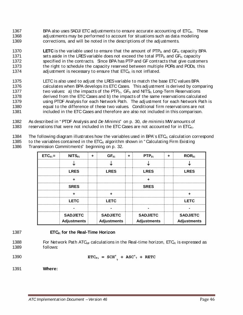
ATC Implementation Document – Version 46 Page 46
BPA also uses SADJ/ETC adjustments to ensure accurate accounting of ETCFi. These 1367 adjustments may be performed to account for situations such as data modeling 1368 corrections, and will be noted in the descriptions of the adjustments. 1369
LETC is the variable used to ensure that the amount of PTPFi and GFFi capacity BPA 1370 sets aside in the LRES variable does not exceed the total PTPFi and GFFi capacity 1371 specified in the contracts. Since BPA has PTP and GF contracts that give customers 1372 the right to schedule the capacity reserved between multiple PORs and PODs, this 1373 adjustment is necessary to ensure that ETCFi is not inflated. 1374
LETC is also used to adjust the LRES variable to match the base ETC values BPA 1375 calculates when BPA develops its ETC Cases. This adjustment is derived by comparing 1376 two values: a) the impacts of the PTPFi, GFFi and NITSFi Long-Term Reservations 1377 derived from the ETC Cases and b) the impacts of the same reservations calculated 1378 using PTDF Analysis for each Network Path. The adjustment for each Network Path is 1379 equal to the difference of these two values. Conditional firm reservations are not 1380 included in the ETC Cases and therefore are also not included in this comparison. 1381
As described in “PTDF Analysis and De Minimis” on p. 30, de minimis MW amounts of 1382 reservations that were not included in the ETC Cases are not accounted for in ETCFi. 1383
The following diagram illustrates how the variables used in BPA’s ETCFi calculation correspond 1384 to the variables contained in the ETCFi algorithm shown in “Calculating Firm Existing 1385 Transmission Commitments” beginning on p. 32. 1386
ETCFi = NITSFi + GFFi + PTPFi + RORFi
↓ ↓ ↓ ↓
LRES LRES LRES LRES
+ +
SRES SRES
+ + +
LETC LETC LETC
- - - -
SADJ/ETC Adjustments
SADJ/ETC Adjustments
SADJ/ETC Adjustments
SADJ/ETC Adjustments
ETCFi for the Real-Time Horizon 1387
For Network Path ATCNF calculations in the Real-time horizon, ETCFi is expressed as 1388 follows: 1389
ETCFi = SCH+7 + ASC+7 + RETC 1390
Where: 1391
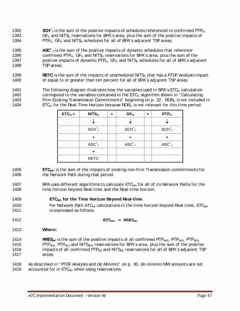
ATC Implementation Document – Version 46 Page 47
SCH+7 is the sum of the positive impacts of schedules referenced to confirmed PTPFi, 1392
GFFi and NITSFi reservations for BPA’s area, plus the sum of the positive impacts of 1393 PTPFi, GFFi and NITSFi schedules for all of BPA’s adjacent TSP areas. 1394
ASC+ 7 is the sum of the positive impacts of dynamic schedules that reference 1395
confirmed PTPFi, GFFi and NITSFi reservations for BPA’s area, plus the sum of the 1396 positive impacts of dynamic PTPFi, GFFi and NITSFi schedules for all of BPA’s adjacent 1397 TSP areas. 1398
RETC is the sum of the impacts of unscheduled NITSFi that has a PTDF Analysis impact 1399 of equal to or greater than ten percent for all of BPA’s adjacent TSP areas. 1400
The following diagram illustrates how the variables used in BPA’s ETCFi calculation 1401 correspond to the variables contained in the ETCFi algorithm shown in “Calculating 1402 Firm Existing Transmission Commitments” beginning on p. 32. RORFi is not included in 1403 ETCFI for the Real-Time Horizon because RORFi is not relevant for this time period. 1404
ETCFi = NITSFi + GFFi + PTPFi
↓ ↓ ↓
SCH+7 SCH+
7 SCH+7
+ + +
ASC+7 ASC+
7 ASC+7
+
RETC
ETCNFi is the sum of the impacts of existing non-firm Transmission commitments for 1405 the Network Path during that period. 1406
BPA uses different algorithms to calculate ETCNFi for all of its Network Paths for the 1407 time horizon beyond Real-time and the Real-time horizon. 1408
ETCNFi for the Time Horizon Beyond Real-time 1409 For Network Path ATCNF calculations in the time horizon beyond Real-time, ETCNFi 1410 is expressed as follows: 1411
ETCNFi = RRESNF 1412
Where: 1413
RRESNF is the sum of the positive impacts of all confirmed PTPNF5i, PTPNF4i, PTPNF3i, 1414 PTPNF2i, PTPNF1i and NITSNF6i reservations for BPA’s area, plus the sum of the positive 1415 impacts of all confirmed PTPNFi and NITSNFi reservations for all of BPA’s adjacent TSP 1416 areas. 1417
As described in “PTDF Analysis and De Minimis” on p. 30, de minimis MW amounts are not 1418 accounted for in ETCNFi when using reservations. 1419

ATC Implementation Document – Version 46 Page 48
The following diagram explains how the variables used in BPA’s ETCNFi calculation correspond 1420 to the variables contained in the ETCNFi algorithm shown in “Calculating Non-Firm Existing 1421 Transmission Commitments” beginning on p. 42. 1422
ETCNFi = NITSNFi + PTPNFi
↓ ↓
RRESNF RRESNF
ETCNFi for the Real-time Horizon 1423 For Network Path ATCNF calculations in the Real-time horizon, ETCNFi is expressed as 1424 follows: 1425
ETCNFi = SCH+6,5,4,3,2,1 + ASC+6,5,4,3,2,1 1426
Where: 1427
SCH+6,5,4,3,2,1 is the sum of the positive impacts of schedules referenced to confirmed 1428
PTPNF2i, PTPNF1i and NITSNF6i reservations for BPA’s area, plus the sum of the positive 1429 impacts of PTPNFi and NITSNFi schedules for all of BPA’s adjacent TSP areas. 1430
ASC+6,5,4,3,2,1 is the sum of positive impacts of dynamic schedules referenced to 1431
confirmed PTPNF2i, PTPNF1i and NITSNF6i reservations for BPA’s area, plus the sum of the 1432 positive impacts of dynamic PTPNFi, GFNFi and NITSNFi schedules for all of BPA’s 1433 adjacent TSP areas. 1434
The following diagram illustrates how the variables used in BPA’s ETCFi calculation correspond 1435 to the variables contained in the ETCFi algorithm shown in “Calculating Non-Firm Existing 1436 Transmission Commitments” beginning on p. 42. 1437
ETCNFi = NITSNFi + PTPNFi
↓ ↓
SCH+6,5,4,3,2,1 SCH+
6,5,4,3,2,1
+ +
ASC+6,5,4,3,2,1 ASC+
6,5,4,3,2,1
CBMSi is the impact of any schedules during that period using Capacity Benefit Margin. 1438
BPA does not maintain CBM. Therefore BPA sets CBMSi at zero for all of its Network 1439 Paths for all time periods. 1440
TRMUi is the impact on the Network Path of the Transmission Reliability Margin for the 1441 Network Path that has not been released for sale (unreleased) as non-firm capacity 1442 during that period. 1443
BPA does not maintain TRM on its Network Paths. Therefore BPA sets TRMUi at zero 1444 for all of its Network Paths for all time periods. 1445

ATC Implementation Document – Version 46 Page 49
PostbacksNFi are changes to non-firm Available Transfer Capability due to a change in 1446 the use of Transmission Service for that period. 1447
Because BPA automatically recalculates ETCFi and ETCNFi whenever there is a 1448 reduction in LRES, SRES, or RRES, BPA does not use PostbacksNFi for calculating 1449 ATCNF for any of its Network Paths in the time horizon beyond Real-time. 1450
BPA also does not use PostbacksNFi for any of its Network Paths for the Real-time 1451 horizon. 1452
Therefore BPA sets PostbacksNFi at zero for all of its Network Paths for the time 1453 horizon beyond Real-time and the Real-time horizon. 1454
CounterflowsNFi are adjustments to non-firm Available Transfer Capability. 1455
Counterflows resulting from firm and non-firm Transmission schedules, excluding 1456 dynamic schedules, are added back to ATCNF in the CounterflowsNFi component. 1457
CounterflowsNFi is the sum of the negative impacts of schedules referenced to 1458 confirmed firm and non-firm reservations in BPA’s area, plus the sum of the 1459 negative impacts of schedules for all of BPA’s adjacent TSP areas. In BPA’s 1460 calculations, CounterflowsNFi is expressed as SCH-
7,6,5,4,3,2,1. 1461
As a result BPA calculates ATCNF for its Network Paths for all time periods as follows: 1462
ATCNF = TTC - ETC
Fi - ETC
NFi + Counterflows
NFi 1463
As described in “Determining Base ETCFi” on p. 33, counterflows are modeled in the ETC 1464 Cases used to determine ETCFi. In some cases, the amount of counterflows on particular 1465 Network Paths result in a negative ETCFi value, which, when subtracted from TTC, results 1466 in ATCNF greater than TTC. In other cases, the amount of CounterflowsNFi exceeds the sum 1467 of the ETCFi and ETCNFi, which, when added to TTC, also results in ATCNF greater than TTC. 1468
IX. Data Sources and Recipients 1469
BPA receives data for use in its ATC calculations, and provides data for use in calculating 1470 transfer and Flowgate capabilities through the WECC base case process described beginning 1471 on p. 2. BPA also directly receives and provides data, such as outage information and specific 1472 Transmission commitments, from and to the following Transmission Service Providers and 1473 Transmission Operators: (MOD-001 R3.3, R3.4) 1474
• Avista Corporation 1475 • BC Hydro 1476 • California Independent System Operator 1477 • City of Tacoma, Department of Public Utilities, Light Division 1478 • Eugene Water and Electric Board 1479 • Fortis BC 1480 • Idaho Power Company 1481
ATC Implementation Document – Version 46 Page 50
• Los Angeles Department of Water and Power 1482 • NV Energy 1483 • NorthWestern Energy 1484 • Pacific Gas & Electric 1485 • PacifiCorp 1486 • Pend Oreille County Public Utility District No. 1 1487 • Portland General Electric 1488 • Public Utility District No. 1 of Chelan County 1489 • Public Utility District No. 1 of Clark County 1490 • Public Utility District No. 1 of Douglas County 1491 • Public Utility District No. 2 of Grant County, Washington 1492 • Public Utility District No. 1 of Snohomish County 1493 • Puget Sound Energy, Inc. 1494 • Sacramento Municipal Utility District 1495 • Seattle City Light 1496 • Southern California Edison 1497 • Transmission Agency of Northern California 1498 • Western Area Power Administration – Sierra Nevada Region 1499 • California Independent System Operator 1500
X. Responding to Data Requests 1501
Upon official request from any Transmission Service Provider, Planning Coordinator, 1502 Reliability Coordinator, or Transmission Operator for any data from the list below, solely for 1503 use in the requestor’s ATC or AFC calculations, BPA will begin to make the data available 1504 within 30 calendar days of receiving the request. 1505
• Expected generation and Transmission outages, additions, and retirements 1506 • Load forecasts 1507 • Unit commitments and order of dispatch, to include all designated resources (BPA does 1508
not have resources that are committed or have the legal obligation to run) 1509 • Firm NITS and non-firm NITS (i.e. Secondary Service) 1510 • Firm and non-firm Transmission reservations 1511 • Grandfathered obligations 1512 • Firm roll-over rights 1513 • Any firm and non-firm adjustments applied by BPA to reflect parallel path impacts 1514 • Power flow models and underlying assumptions 1515 • Contingencies, provided in one or more of the following formats: 1516
o A list of Elements 1517 o A list of Network Paths 1518
ATC Implementation Document – Version 46 Page 51
o A set of selection criteria that can be applied to the WECC base cases used by 1519 BPA 1520
• Facility Ratings 1521 • Any other service that impact ETCs 1522 • Values of CBM and TRM for all ATC Paths 1523 • Values of TTC and ATC for all ATC Paths 1524 • Source and sink identification and mapping to the WECC base cases 1525
BPA will make this data available on the schedule specified by the requestor (but no more 1526 frequently than once per hour, unless mutually agreed to by the requestor and Bonneville). 1527
For a Transmission Service Provider, Planning Coordinator, Reliability Coordinator, or 1528 Transmission Operator to officially request data to use in ATC or AFC calculations, the 1529 requestor must fill out the Data Request Form (MOD-001 R9) found on BPA’s website 1530 http://transmission.bpa.gov/business/atc_methodology/. The completed request form must 1531 be sent to [email protected] with Data request Form (MOD-001 R9) in the subject 1532 line. (MOD-001 R9) 1533
XI. ATCID Revisions 1534
BPA will notify the entities contained in ATCID TP Distribution List when implementing a new 1535 or revised ATCID and make its current ATCID available. (MOD-001 R4, R5) 1536
XII. Version History 1537
ATCID Revision History
Version Date Revised Description of Changes Prepared by
1.0 03/30/2011 BPA ATCID FINAL S Long L Trolese
C Etheridge
2.0 05/11/2011 P.31 Table 2 BPA Flowgates: Corrected the definition of the West of McNary Flowgate by replacing McNary – Horse Heaven 230 kV line with Harvalum – Big Eddy #1 230 kV line in the West of McNary Flowgate Transmission Line Components
L Trolese
3.0 08/11/2011 P. 7 line 114: Revised frequency of hourly calculations from at least three times per hour to at least once per hour.
P. 12-13 Table 1 BPA Paths: Added Montana-Northwest to
L Trolese
ATC Implementation Document – Version 46 Page 52
ATCID Revision History
the Path Name; added Garrison 500 kV 1 and 2 to the Transmission Line Components of the West of Garrison E>W and W>E Paths and revised the Montana Intertie Transmission Line Component from Broadview – Garrison 500 kV 1 and 2 to Townsend-Garrison 500 kV 1 and 2 to be effective October 1, 2011.
P. 17 lines 395-397: Revised sentence to include Montana Intertie as an ATC Path that is limited by contract.
P. 18 lines 440-445: Revised paragraph to include Montana Intertie as an ATC Path where another TOP sets the TTC.
P. 19 line 483-486 and P. 40 line 1102: Added forecasted network resources to be included in Network Integration Transmission Service
P. 20 line 517: corrected reference from ETC to ATCNF.
P. 20 line 531; P. 22 ETCF variable diagram, P. 25 line 669, P. 26 ETCF variable diagram, P. 47 line 1324, P. 49 ETCF variable diagram, P. 53 line 1493 and P. 54 ETCF variable diagram: Corrected ETCF formula to subtract SADJ/ETC Adjustments instead of add it.
P. 27 lines 724-726 and P. 55 lines 1549-1551: Updated reason for why RORF is not included in the real-time horizon.
P. 29 line 789: Deleted “implemented” from which schedules impact counterflows.
P. 30 lines 798-800: Added a note describing the variable RADJ/Congestion Management and how it impacts ATC calculations.
P. 44: Corrected footnote 7 to align it with the reference.
P. 47: Deleted language referring to including adjacent TSP reservations in interim ETCFi.
P. 53 lines 1517-1521: Added paragraph describing LETC that was mistakenly left out in Version 1.0 and 2.0.
P. 57 line 1604: Deleted “confirmed” from which schedules impact counterflows.
P. 58: Replaced table delineating the NERC registered functions of the entities with a bulleted list of the entities.
ATC Implementation Document – Version 46 Page 53
ATCID Revision History
Appendix A: Updated List of Contracts and Specific Paths with Shared Ownership to indicate the Colstrip Project on the Montana Intertie Path will no longer be represented as an allocation agreement after October 1, 2011.
Appendix C: Updated the SOL Methodology.
Appendix D: Updated BPA’s NITS, GF, and PTP Agreements to include the Colstrip Project and other contracts that have been added since February 3, 2011.
4.0 09/30/2011 P. 27 lines 720 – 722 and ETCF variable diagram: added new use for RADJ/ETC Adjustments variable.
L Trolese
5.0 10/20/2011 P. 39 lines 1068-1070, P. 40 lines 1077-1079 and lines 1087-1089: Removed language referring to the month of August.
P. 40 lines 1103-1114, P. 41 lines 1118-1128 and P. 48 lines 1325-1331: added paragraph describing how BPA accounts for the impacts of its adjacent TSP firm NITS and PTP Transmission Service.
L Trolese
6.0 11/1/2011 P.31 Table 2 BPA Flowgates: Added the McNary – John Day #2 500 kV line to the West of McNary Flowgate definition.
Appendix C: Updated the SOL Methodology.
L Beckman
7.0 11/10/2011 P. 40 line 1103 and P.41 line 1118: Changed effective date from November 8th to no later than November 15, 2011 for incorporating adjacent TSP TSRs into AFC calculations.
L Beckman
8.0 02/03/2012 P. 35 line 907: Added paragraph describing how BPA prepares for the addition of a flowgate. L
Beckman
9.0 02/13/2012 P. 5, P. 22, P. 29: Defined BPA’s TRM practice for the Northern Intertie S>N Path. P. 20 line 528 and P. 23 line 597: Replaced NI Holdout in the ATCF formula with TRM.
L Beckman
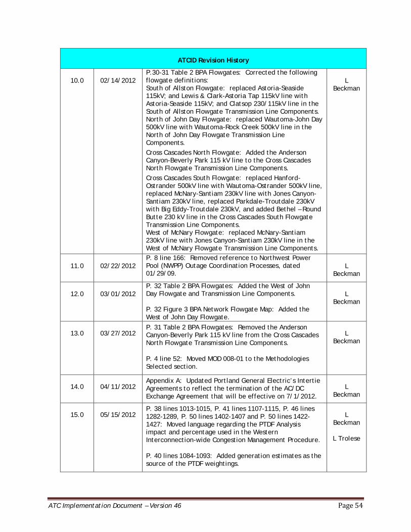
ATC Implementation Document – Version 46 Page 54
ATCID Revision History
10.0 02/14/2012 P.30-31 Table 2 BPA Flowgates: Corrected the following flowgate definitions: South of Allston Flowgate: replaced Astoria-Seaside 115kV; and Lewis & Clark-Astoria Tap 115kV line with Astoria-Seaside 115kV; and Clatsop 230/115kV line in the South of Allston Flowgate Transmission Line Components. North of John Day Flowgate: replaced Wautoma-John Day 500kV line with Wautoma-Rock Creek 500kV line in the North of John Day Flowgate Transmission Line Components. Cross Cascades North Flowgate: Added the Anderson Canyon-Beverly Park 115 kV line to the Cross Cascades North Flowgate Transmission Line Components. Cross Cascades South Flowgate: replaced Hanford-Ostrander 500kV line with Wautoma-Ostrander 500kV line, replaced McNary-Santiam 230kV line with Jones Canyon-Santiam 230kV line, replaced Parkdale-Troutdale 230kV with Big Eddy-Troutdale 230kV, and added Bethel – Round Butte 230 kV line in the Cross Cascades South Flowgate Transmission Line Components. West of McNary Flowgate: replaced McNary-Santiam 230kV line with Jones Canyon-Santiam 230kV line in the West of McNary Flowgate Transmission Line Components.
L Beckman
11.0 02/22/2012 P. 8 line 166: Removed reference to Northwest Power Pool (NWPP) Outage Coordination Processes, dated 01/29/09.
L Beckman
12.0 03/01/2012 P. 32 Table 2 BPA Flowgates: Added the West of John Day Flowgate and Transmission Line Components. P. 32 Figure 3 BPA Network Flowgate Map: Added the West of John Day Flowgate.
L Beckman
13.0 03/27/2012 P. 31 Table 2 BPA Flowgates: Removed the Anderson Canyon-Beverly Park 115 kV line from the Cross Cascades North Flowgate Transmission Line Components.
P. 4 line 52: Moved MOD 008-01 to the Methodologies Selected section.
L Beckman
14.0 04/11/2012 Appendix A: Updated Portland General Electric’s Intertie Agreements to reflect the termination of the AC/DC Exchange Agreement that will be effective on 7/1/2012.
L Beckman
15.0 05/15/2012 P. 38 lines 1013-1015, P. 41 lines 1107-1115, P. 46 lines 1282-1289, P. 50 lines 1402-1407 and P. 50 lines 1422-1427: Moved language regarding the PTDF Analysis impact and percentage used in the Western Interconnection-wide Congestion Management Procedure.
P. 40 lines 1084-1093: Added generation estimates as the source of the PTDF weightings.
L Beckman
L Trolese
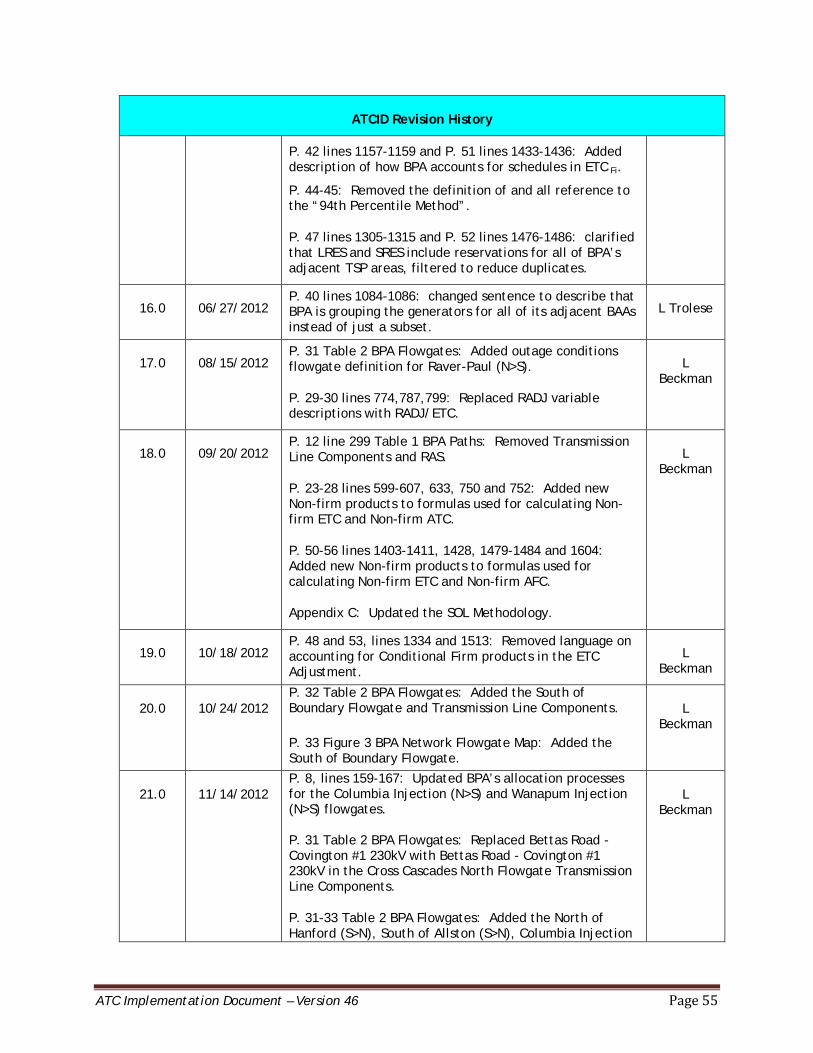
ATC Implementation Document – Version 46 Page 55
ATCID Revision History
P. 42 lines 1157-1159 and P. 51 lines 1433-1436: Added description of how BPA accounts for schedules in ETC Fi.
P. 44-45: Removed the definition of and all reference to the “94th Percentile Method”.
P. 47 lines 1305-1315 and P. 52 lines 1476-1486: clarified that LRES and SRES include reservations for all of BPA’s adjacent TSP areas, filtered to reduce duplicates.
16.0 06/27/2012 P. 40 lines 1084-1086: changed sentence to describe that BPA is grouping the generators for all of its adjacent BAAs instead of just a subset.
L Trolese
17.0 08/15/2012 P. 31 Table 2 BPA Flowgates: Added outage conditions flowgate definition for Raver-Paul (N>S).
P. 29-30 lines 774,787,799: Replaced RADJ variable descriptions with RADJ/ETC.
L Beckman
18.0 09/20/2012 P. 12 line 299 Table 1 BPA Paths: Removed Transmission Line Components and RAS.
P. 23-28 lines 599-607, 633, 750 and 752: Added new Non-firm products to formulas used for calculating Non-firm ETC and Non-firm ATC.
P. 50-56 lines 1403-1411, 1428, 1479-1484 and 1604: Added new Non-firm products to formulas used for calculating Non-firm ETC and Non-firm AFC.
Appendix C: Updated the SOL Methodology.
L Beckman
19.0 10/18/2012 P. 48 and 53, lines 1334 and 1513: Removed language on accounting for Conditional Firm products in the ETC Adjustment.
L Beckman
20.0 10/24/2012 P. 32 Table 2 BPA Flowgates: Added the South of Boundary Flowgate and Transmission Line Components. P. 33 Figure 3 BPA Network Flowgate Map: Added the South of Boundary Flowgate.
L Beckman
21.0 11/14/2012 P. 8, lines 159-167: Updated BPA’s allocation processes for the Columbia Injection (N>S) and Wanapum Injection (N>S) flowgates. P. 31 Table 2 BPA Flowgates: Replaced Bettas Road - Covington #1 230kV with Bettas Road - Covington #1 230kV in the Cross Cascades North Flowgate Transmission Line Components.
P. 31-33 Table 2 BPA Flowgates: Added the North of Hanford (S>N), South of Allston (S>N), Columbia Injection
L Beckman
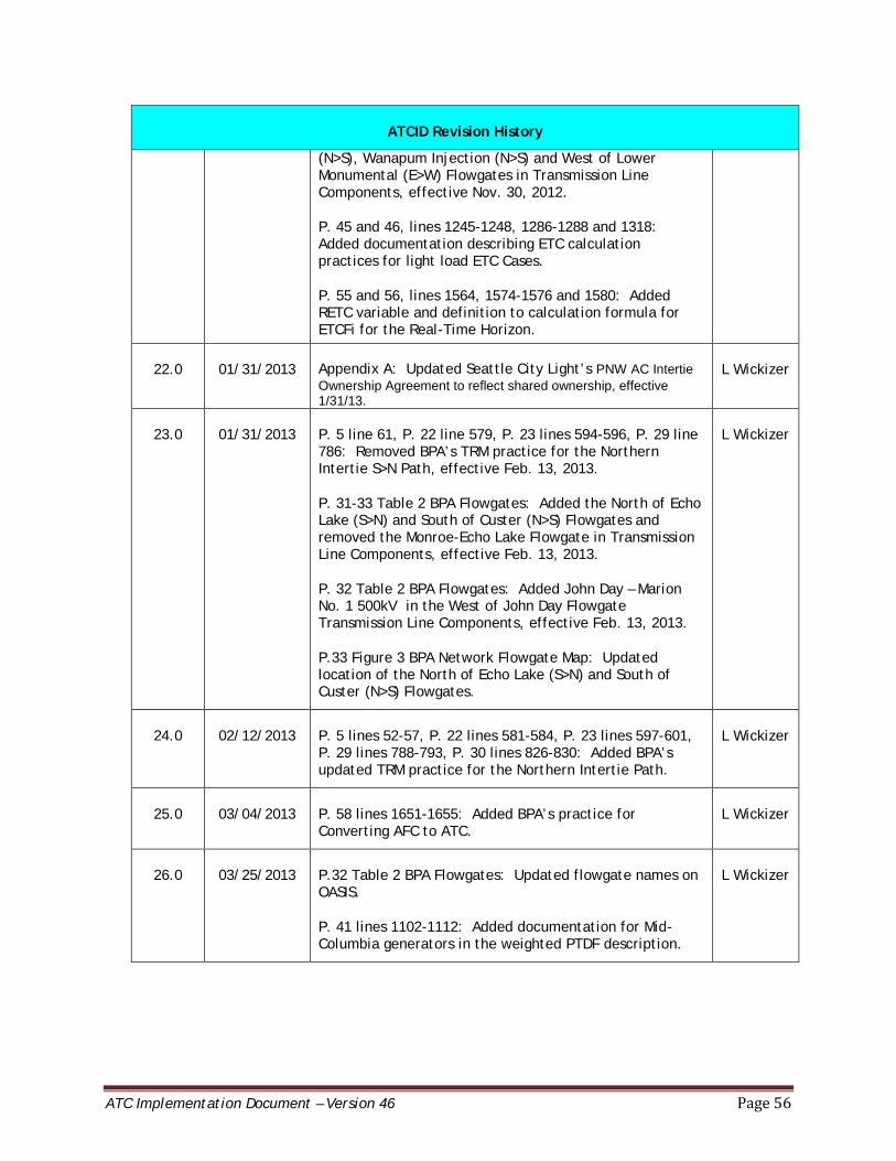
ATC Implementation Document – Version 46 Page 56
ATCID Revision History
(N>S), Wanapum Injection (N>S) and West of Lower Monumental (E>W) Flowgates in Transmission Line Components, effective Nov. 30, 2012.
P. 45 and 46, lines 1245-1248, 1286-1288 and 1318: Added documentation describing ETC calculation practices for light load ETC Cases.
P. 55 and 56, lines 1564, 1574-1576 and 1580: Added RETC variable and definition to calculation formula for ETCFi for the Real-Time Horizon.
22.0 01/31/2013 Appendix A: Updated Seattle City Light’s PNW AC Intertie Ownership Agreement to reflect shared ownership, effective 1/31/13.
L Wickizer
23.0 01/31/2013 P. 5 line 61, P. 22 line 579, P. 23 lines 594-596, P. 29 line 786: Removed BPA’s TRM practice for the Northern Intertie S>N Path, effective Feb. 13, 2013.
P. 31-33 Table 2 BPA Flowgates: Added the North of Echo Lake (S>N) and South of Custer (N>S) Flowgates and removed the Monroe-Echo Lake Flowgate in Transmission Line Components, effective Feb. 13, 2013.
P. 32 Table 2 BPA Flowgates: Added John Day – Marion No. 1 500kV in the West of John Day Flowgate Transmission Line Components, effective Feb. 13, 2013.
P.33 Figure 3 BPA Network Flowgate Map: Updated location of the North of Echo Lake (S>N) and South of Custer (N>S) Flowgates.
L Wickizer
24.0 02/12/2013 P. 5 lines 52-57, P. 22 lines 581-584, P. 23 lines 597-601, P. 29 lines 788-793, P. 30 lines 826-830: Added BPA’s updated TRM practice for the Northern Intertie Path.
L Wickizer
25.0 03/04/2013 P. 58 lines 1651-1655: Added BPA’s practice for Converting AFC to ATC.
L Wickizer
26.0 03/25/2013 P.32 Table 2 BPA Flowgates: Updated flowgate names on OASIS.
P. 41 lines 1102-1112: Added documentation for Mid-Columbia generators in the weighted PTDF description.
L Wickizer

ATC Implementation Document – Version 46 Page 57
ATCID Revision History
27.0 05/01/2013 P. 38-39 lines 993-1002: Updated BPA’s process for mapping and incorporating outages into the WECC base case.
Appendix A: Updated Avista’s West of Hatwai Ownership Agreement number.
L Wickizer
28.0 05/15/2014 P. 7-8 lines 123-127, 131-134, 142-143, 149-150: Language clarification in Limiting Assumptions section.
P. 9 lines 178-203: Updated BPA’s process for outage planning.
P. 10 lines 209 – 222: Language clarification on Daily and Hourly TTC and TFC Calculations.
P. 10-11 lines 238 – 272: Language clarification on SOL Priorities Used to Set TTC and TFC.
P. 37, lines 884-885, 892: Language clarification on SOL study process.
P. 38, lines 952-953: Language clarification on SOL study process.
P. 39, line 965: Language clarification on TFC calculation.
Appendix C: Updated the SOL Methodology.
M Olczak
29.0 05/31/2014 P. 33 Table 2 BPA Flowgates: Added outage conditions flowgate definition for West of McNary.
M Olczak
30.0 7/24/2014 P. 32 Table 2 BPA Flowgates: Changed Olympia – South Tacoma 230kV to St. Clair – South Tacoma 230kV in the Raver-Paul section. P. 36 Table 3 Interfaces with BAs Adjacent to BPA: Added Gridforce Energy Management as a BA-BA interconnection. P. 36 Table 3 Interfaces with BAs Adjacent to BPA: Updated to show Portland General Electric and Seattle City Light also have connections accounted for with paths that use the Rated System Path Methodology.
P. 5 Clarification on number of BAs within the WECC area
J Ofstead
31.0 09/13/2014 P. 33 Table 2 BPA Flowgates: Updated West of McNary flowgate definition during outages. J Ofstead
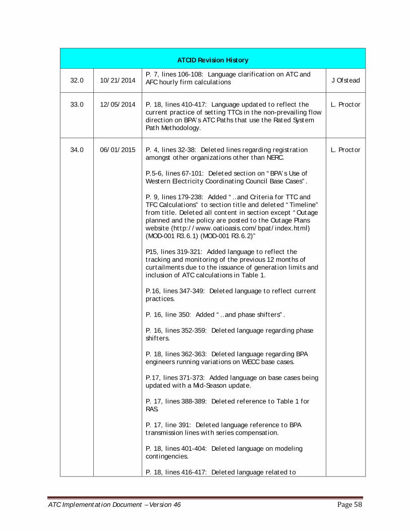
ATC Implementation Document – Version 46 Page 58
ATCID Revision History
32.0 10/21/2014 P. 7, lines 106-108: Language clarification on ATC and AFC hourly firm calculations J Ofstead
33.0 12/05/2014 P. 18, lines 410-417: Language updated to reflect the current practice of setting TTCs in the non-prevailing flow direction on BPA’s ATC Paths that use the Rated System Path Methodology.
L. Proctor
34.0 06/01/2015 P. 4, lines 32-38: Deleted lines regarding registration amongst other organizations other than NERC.
P.5-6, lines 67-101: Deleted section on “BPA’s Use of Western Electricity Coordinating Council Base Cases”.
P. 9, lines 179-238: Added “…and Criteria for TTC and TFC Calculations” to section title and deleted “Timeline” from title. Deleted all content in section except “Outage planned and the policy are posted to the Outage Plans website (http://www.oatioasis.com/bpat/index.html) (MOD-001 R3.6.1) (MOD-001 R3.6.2)”
P15, lines 319-321: Added language to reflect the tracking and monitoring of the previous 12 months of curtailments due to the issuance of generation limits and inclusion of ATC calculations in Table 1.
P.16, lines 347-349: Deleted language to reflect current practices.
P. 16, line 350: Added “…and phase shifters”.
P. 16, lines 352-359: Deleted language regarding phase shifters.
P. 18, lines 362-363: Deleted language regarding BPA engineers running variations on WECC base cases.
P.17, lines 371-373: Added language on base cases being updated with a Mid-Season update.
P. 17, lines 388-389: Deleted reference to Table 1 for RAS.
P. 17, line 391: Deleted language reference to BPA transmission lines with series compensation.
P. 18, lines 401-404: Deleted language on modeling contingencies.
P. 18, lines 416-417: Deleted language related to
L. Proctor
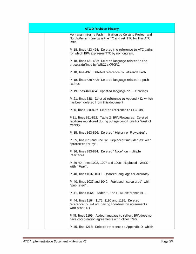
ATC Implementation Document – Version 46 Page 59
ATCID Revision History
Montanan Intertie Path limitation by Colstrip Project and NorthWestern Energy is the TO and set TTC for this ATC Path.
P. 18, lines 423-424: Deleted the reference to ATC paths for which BPA expresses TTC by nomongram.
P. 18, lines 431-432: Deleted language related to the process defined by WECC’s OTCPC.
P. 18, line 437: Deleted reference to LaGrande Path.
P. 18, lines 438-442: Deleted language related to path ratings.
P. 19 lines 460-484: Updated language on TTC ratings.
P. 21, lines 538: Deleted reference to Appendix D, which has been deleted from this document.
P.30, lines 820-822: Deleted reference to DSO 319.
P.31, lines 851-852: Table 2, BPA Flowgates: Deleted facilities monitored during outage conditions for West of McNary.
P. 35, lines 863-866: Deleted “History or Flowgates”.
P. 35, line 873 and line 87: Replaced “included as” with “protected for by”.
P. 36, lines 883-884: Deleted “Note” on multiple interfaces.
P. 39-40, lines 1002, 1007 and 1008: Replaced “WECC” with “Peak”.
P. 40, lines 1032-1033: Updated language for accuracy.
P. 40, lines 1037 and 1049: Replaced “calculated” with “published”.
P. 41, lines 1064: Added “…the PTDF difference is…”.
P. 44, lines 1164, 1175, 1190 and 1195: Deleted reference to BPA not having coordination agreements with other TSP.
P.45, lines 1199: Added language to reflect BPA does not have coordination agreements with other TSPs.
P. 45, line 1213: Deleted reference to Appendix D, which
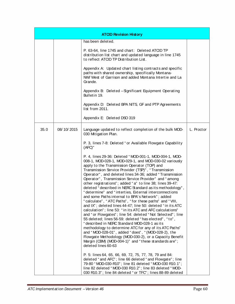
ATC Implementation Document – Version 46 Page 60
ATCID Revision History
has been deleted.
P. 63-64, line 1745 and chart: Deleted ATCID TP distribution list chart and updated language in line 1745 to reflect ATCID TP Distribution List.
Appendix A: Updated chart listing contracts and specific paths with shared ownership, specifically Montana-NW/West of Garrison and added Montana Intertie and La Grande.
Appendix B: Deleted – Significant Equipment Operating Bulletin 19.
Appendix D: Deleted BPA NITS, GF and PTP Agreements list from 2011.
Appendix E: Deleted DSO 319
35.0 08/10/2015 Language updated to reflect completion of the bulk MOD-030 Mitigation Plan.
P. 3, lines 7-8: Deleted “or Available Flowgate Capability (AFC)”
P. 4, lines 29-36: Deleted “MOD-001-1, MOD-004-1, MOD-008-1, MOD-028-1, MOD-029-1, and MOD-030-02 variously apply to the Transmission Operator (TOP) and Transmission Service Provider (TSP)”, “Transmission Operator”, and deleted lines 34-36; added “Transmission Operator”, Transmission Service Provider” and “among other registrations”; added “a” to line 38; lines 39-47: deleted “described in NERC Standard as its methodology”, “determine” and “interties, External interconnections and some Paths internal to BPA’s Network”; added “calculate”, “ATC Paths”, “for these paths” and “VIII, and IX”; deleted lines 44-47; line 50: deleted “in its ATC calculation”; line 53: “in its ATC and AFC calculations” and “or Flowgates”; line 54: deleted “Not Selected”; line 55 deleted; lines 56-59: deleted “has elected”, “to”, “described in NERC Standard MOD-028-1 as its methodology to determine ATC for any of its ATC Paths” and “MOD-028-01”, added “does”, “(MOD-028-2), the Flowgate Methodology (MOD-030-2), or a Capacity Benefit Margin (CBM) (MOD-004-1)” and “these standards are”; deleted lines 60-63
P. 5: lines 64, 65, 66, 69, 72, 75, 77, 78, 79 and 84: deleted “and AFC”; line 66 deleted “and Flowgate”; line 79-80 “MOD-030-R10”; line 81 deleted “MOD-030 R10.1”; line 82 deleted “MOD-030 R10.2”; line 83 deleted “MOD-030 R10.3”; line 84 deleted “or TFC”; lines 88-89 deleted
L. Proctor
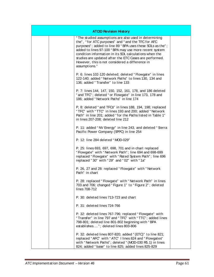
ATC Implementation Document – Version 46 Page 61
ATCID Revision History
“The studied assumptions are also used in determining the”, “for ATC purposes” and “and the TFC for AFC purposes”; added to line 89 “BPA uses these SOLs as the”; added to lines 97-100 “BPA may use more recent system condition information in its SOL calculations when the studies are updated after the ETC Cases are performed. However, this is not considered a difference in assumptions.”
P. 6: lines 102-120 deleted; deleted “Flowgate” in lines 122-140; added “Network Paths” to lines 130, 134 and 136; added “Transfer” to line 133
P. 7: lines 144, 147, 150, 152, 161, 178, and 186 deleted “and TFC”; deleted “or Flowgate” in line 173, 178 and 186; added “Network Paths” in line 174
P, 8: deleted “and TFCs” in lines 188, 194, 198; replaced “TFC” with “TTC” in lines 193 and 200; added “Network Path” in line 201; added “for the Paths listed in Table 1” in lines 207-208; deleted line 212
P. 11: added “NV Energy” in line 243, and deleted “Sierra Pacific Power Company (SPPC) in line 254
P. 12: line 284 deleted “MOD-029”
P. 25: lines 693, 697, 698, 701 and in chart replaced “Flowgate” with “Network Path”; line 694 and 698-699 replaced “Flowgate” with “Rated System Path”; line 696 replaced “30” with “29” and “02” with “1a”
P. 26, 27 and 28: replaced “Flowgate” with “Network Path” in chart
P. 28: replaced “Flowgate” with “Network Path” in lines 703 and 706; changed “Figure 1” to “Figure 2”; deleted lines 708-712
P. 30: deleted lines 713-723 and chart
P. 31: deleted lines 724-766
P. 32: deleted lines 767-796; replaced “Flowgate” with “Transfer” in line 797 and “TFC” with “TTC”; added lines 798-801; deleted line 801-802 beginning with “BPA establishes…..”; deleted lines 803-806
P. 32: deleted lines 807-820; added “(ETC)” to line 821; replaced “AFC” with “ATC” I lines 824 and “Flowgates” with “Network Paths”; deleted “(MOD-030 R5.1) in lines 824; added “base” to line 825; added lines 825-829
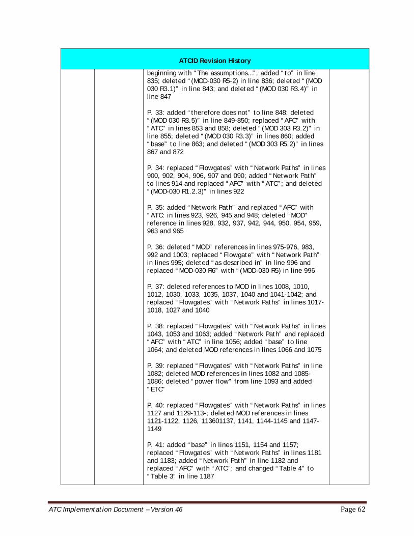
ATC Implementation Document – Version 46 Page 62
ATCID Revision History
beginning with “The assumptions…”; added “to” in line 835; deleted “(MOD-030 R5-2) in line 836; deleted “(MOD 030 R3.1)” in line 843; and deleted “(MOD 030 R3.4)” in line 847
P. 33: added “therefore does not” to line 848; deleted “(MOD 030 R3.5)” in line 849-850; replaced “AFC” with “ATC” in lines 853 and 858; deleted “(MOD 303 R3.2)” in line 855; deleted “(MOD 030 R3.3)” in lines 860; added “base” to line 863; and deleted “(MOD 303 R5.2)” in lines 867 and 872
P. 34: replaced “Flowgates” with “Network Paths” in lines 900, 902, 904, 906, 907 and 090; added “Network Path” to lines 914 and replaced “AFC” with “ATC”; and deleted “(MOD-030 R1.2.3)” in lines 922
P. 35: added “Network Path” and replaced “AFC” with “ATC: in lines 923, 926, 945 and 948; deleted “MOD” reference in lines 928, 932, 937, 942, 944, 950, 954, 959, 963 and 965
P. 36: deleted “MOD” references in lines 975-976, 983, 992 and 1003; replaced “Flowgate” with “Network Path” in lines 995; deleted “as described in” in line 996 and replaced “MOD-030 R6” with “(MOD-030 R5) in line 996
P. 37: deleted references to MOD in lines 1008, 1010, 1012, 1030, 1033, 1035, 1037, 1040 and 1041-1042; and replaced “Flowgates” with “Network Paths” in lines 1017-1018, 1027 and 1040
P. 38: replaced “Flowgates” with “Network Paths” in lines 1043, 1053 and 1063; added “Network Path” and replaced “AFC” with “ATC” in line 1056; added “base” to line 1064; and deleted MOD references in lines 1066 and 1075
P. 39: replaced “Flowgates” with “Network Paths” in line 1082; deleted MOD references in lines 1082 and 1085-1086; deleted “power flow” from line 1093 and added “ETC”
P. 40: replaced “Flowgates” with “Network Paths” in lines 1127 and 1129-113-; deleted MOD references in lines 1121-1122, 1126, 113601137, 1141, 1144-1145 and 1147-1149
P. 41: added “base” in lines 1151, 1154 and 1157; replaced “Flowgates” with “Network Paths” in lines 1181 and 1183; added “Network Path” in line 1182 and replaced “AFC” with “ATC”; and changed “Table 4” to “Table 3” in line 1187

ATC Implementation Document – Version 46 Page 63
ATCID Revision History
P. 42: replaced “Flowgates” with “Network Paths” in lines 1197, 1200, 1204 and 1206; deleted references to MOD in lines 1198 and 1206; added “Transfer” in lines 1199, 1204 and 1206; replaced “AFC” with “ATC” in lines 1199, 1200, 1202 and 1204; added “(MOD-029 R7) in line 1201
P. 43: replaced “Flowgate” with “Transfer” in lines 1208, 1220, 1225, 1229 and 1233; replaced “TFC” with “TTC” in line 1209; replaced “Flowgates” with “Network Path” in lines 1210-1211; and deleted “base” I line 1219
P, 44: replaced “Flowgate” with “Network Path” in lines 1246, 1247, 1256, 1258-1259, 1260, 1262, 1263, 1267-1269 and 1269; deleted MOD reference in 1255’ changed “AFC” to “ATC” in line 1264 and 1267
P. 45: changed “AFC” to “ATC” in lines 1271, 1278, 1280, 1283 and 1307; replaced “Flowgate” with “Network Path” in lines 1272, 1277, 1278 and 1282; replaced “Flowgate” with “Transfer” in line 1274
P. 46: replaced “Flowgate” with “Network Path” in lines 1309 and 1330; deleted “as described in MOD-030 R7” in line1311; added “(MOD-029 R6)” to line 1311; and deleted references to MODs in lines 1316, 1322, 1325, 1327, 1337 and 1343
P. 47: replaced “Flowgate” with “Network Path” in lines 1346, 1348, 1353-1354 and 1360; removed “(MOD-030 R7.7)” in line 1345; added “Network Path” to line 1356 and replaced “AFC” with “ATC”; replaced “Flowgate” with “Transfer” in line 1358; replaced “AFC” with “ATC” in lines 1358, 1359, 1367, 1369, 1377, 1379 and 1381
P. 48: replaced “AFC” with “ATC” in lines 1382, 1385, 1387, 1389 and 1400; replaced “Flowgate” with “Network Path” in lines 1382, 1387-1388, 1391, 1396, 1397-1398; replaced “TFC” with “TTC” in line 1385; replaced “Flowgate” with “Transfer” in lines 1387, 1391, 1393, 1409 and 1414; added “Network Path” to line 1400; and deleted “base” from line 1413
P. 49: replaced “Flowgate” with “Transfer” in lines 1418 and 1422; replaced “Flowgate” with “Network Path” in lines 1435 and 1436
P. 50: added “Network Path” in lines 1445 and 1467 and changed “AFC” to “ATC”; deleted MOD reference in line 1451; replaced “Flowgate” with “Network Path” in lines 1463 and 1464
P. 51: added “Network Path” to line 1481 and replaced
ATC Implementation Document – Version 46 Page 64
ATCID Revision History
“AFC” with “ATC”; and replaced “Flowgate” with “Network Path” in line 1497
P. 52: replaced “Flowgate” with “Network Path” in lines 1498, 1499, 1501, 1502, 1507, 1508, 1510, 1519 and 1524; replaced “Flowgate” with “Transfer” in lines 1503 and 1512; replaced “AFC” with “ATC” in lines 1507, 1514, 1519, 1521, 1525, 1527; replaced “TFC” with “TTC” in lines 1521, 1525, 1526 and 1527; and deleted lines 1528-1532
P. 53-57: added lines 1339-1516
P. 58: deleted “and AFC” in line 1713; changed “Nevada Power” to “NV Energy” in line 1726; deleted “(PAC)” from line 1729; and deleted “Sierra Pacific Power Company” from line 1740
P. 59: replaced “Flowgates” with “Network Path” in line 1762; deleted “and Flowgates” in line 1766; and deleted line 1767
36.0 8/28/15 Moved Appendix B: System Operating Limit Methodology for the Operations Horizon; Appendix 1 – TPL-001-0.1System Performance Under Normal Conditions; and Appendix 2 – TPL-001-WECC-RBP-2.1 into a separate document titled “System Operating Limit Methodology for the Operations Horizon “ and posted on the same website astheATCIDat: http://www.bpa.gov/transmission/Doing%20Business/Pages/default.aspx under the ATC Methodology.
L. Proctor
37.0 9/29/15 Deleted reference to the Appendix B SOL in line 253 and added the SOL website address on BPA’s ATC Methodology website in lines 255-257; deleted lines 258-263 regarding prevailing and non-prevailing directions of flow (MOD-029 R2.2) and inserted new language; removed reference to Appendix B: SOL in line 253 and added link to the SOL in line 25; and deleted in Appendix A for the COI, under the Contract Party Seattle City Light “EDF Trading North America LLC and Southern California Edison Company (Effective 1/31/2013)”, under Contrat Number deleted “13ZZ-15826 (formerly” and added under Contract Description, Consent Agreement, Contract Party “Under consent agreement and EDF Trading North American LLC”.
L. Proctor
38.0 11/02/15 Removed reference to Appendix B in line 298 and added link to SOL; updated Table 2, BPA Network Paths table beginning on line 656 for the North of John Day On OASIS: NOJDAY path changed from Watuoma-Ostrander to Wautoma-Knight and the Cross Cascades South on OASIS: C-CACS_S changed from Wautoma-Ostrander to Knight-Ostrander and deleted in Appendix A the Contract Party Seattle City Light Consent Agreement Contract Number
L. Proctor
ATC Implementation Document – Version 46 Page 65
ATCID Revision History
10TX-15107 from the COI path.
39.0 12/07/15 Updated Outage Plan website link in line 104-105 from OASIS http://www.oatioasis.com/bpat/index.html to http://www.gpa.gov/transmission/Reports/Pages/Proposed-Outages.aspx; moved “(MOD-001 R3.6.1) (MOD-001 R.3.6.2)” to line 115; and added outage language in lines 106-115.
L. Proctor
40.0 1/03/16 p. 12, lines 241-255: Replaced “beyond two weeks” with “from the next day and beyond” and “periods within the next two weeks” with “the Real-time horizon” and added “On West of Garrison” and “On Northern Intertie South to North, for the seasons or time periods in which the seasonal studies have not been completed, the last year’s seasonal study results will be used for setting the TTC for the relevant Path. ”
p. 17, lines 430-435: Added “BPA also uses SADJ adjustments on the Northern Intertie Path 3 S>N. These adjustments are used to account for uncertainties on the path caused by simultaneous interaction with paths COI and NOH. The SADJ is being used temporarily while BPA tests and implements an additional 450MW TRM value for this path. BPA will stop using SADJ for this purpose on NI S>N once testing of the additional TRM value is complete and it is implemented.”
p. 21, lines 564-569: Added “In addition, BPA uses SADJ adjustments on the Northern Intertie Path 3 S>N. These adjustments are used to account for uncertainties on the path caused by simultaneous interaction with paths COI/NOH. The SADJ is being used temporarily while BPA tests and implements and additional 450MW TRM value for this path. BPA will stop using SADJ for this purpose on NI S>N once testing of the additional TRM value is complete and it is implemented.”
p. 24, lines 647-649: Added “50 MW “ and “However, BPA does release the additional 450 MW TRM for the Northern Intertie Path S>N as non-firm capacity.”
L. Proctor
41.0 9/06/2016 p. 11, line 243: Added “On West of Garrison,”; line 249: Added “On Northern Intertie South to North,”; lines 252-253: Added “from the next day and beyond.” and “the Real-time horizon”
L. Proctor
ATC Implementation Document – Version 46 Page 66
ATCID Revision History
p. 16, line 430-431: Added “SADJ” and “reflect the TRM across this path that”; deleted lines 433-436
p. 20, line 565: Added “SADJ”, “reflect the TRM across this path that” and “and”; deleted lines 567-570
p. 23, Deleted lines 648-650; added in lines 650-652: “BPA does not release the TRM Due to simultaneous path interactions for the Northern Intertie Path S>N as non-firm capacity, but does not release the remaining TRM as non-firm capacity”
42.0 11/01/2016 Table of Contents: Deleted section IX. BA to BA Interconnection Methodology per BPA decision to no longer utilize this methodology
p. 26, Table 2, BPA Network Paths starting on line 693: Added to Paul-Allston on OASIS: PAUL_ALSN, column Transmission Line Components “During outage conditions of the Paul-Allston #2 500kV line with either of the Paul-Napavine #1 or Napavine-Allston #1 500kV lines, the following lines are monitored: Napavine-Allston #1 500kV; Paul-Allston #2 500kV; Longview-Chehalis #1 & #3 230kV; Holcomb-Naselle #1 115kV
p.34, lines 930-931: Deleted “and light load ETC Cases for the month of January”
p. 36-37, lines 967-1001: Replaced “90th Percentile Method” with “Nameplate Adjusted Method”; replaced “each project’s 90th percentile of historic generation by project and month” with “the nameplate for each project and then adjusting such nameplates by outages forecasted for the particular plants. Next in the month of August, the Lower Snake plants (Lower Granite, Lower Monumental, Little Goose and Ice Harbor) are capped at the observed project outflow over the past ten Augusts.”; deleted lines 975-986; added lines 986-995; deleted lines 998-1001
p. 37, lines 1007-1011: Replaced “modeled at up to 80 percent of the wind generators’ contract Demands for BPA’s area and all adjacent TSP area” with “set at the greater of the following: Modeled on the 100 percent of the contract demand for the wind generator; or Modeled off and replaced by the “Balancing Logic Method”
p. 37, line1020: Replaced “90th Percentile” with “Nameplate Adjusted” and “on p. 35” with “above
p. 37, lines 1032-1035: Deleted “the Mid-Columbia Hydro Projects by 50 percent of the excess generation and FCRPS generation by the other 50 percent of the; added
L. Proctor
ATC Implementation Document – Version 46 Page 67
ATCID Revision History
“Prorata, except for the stress FCRPS zone, see below”; and replaced “90th Percentile” with “Balancing Logic”
p. 38, lines 1039-1041: Deleted lines
p. 38, 1043-1051: Replaced “two” with “three”; replaced “NITSfi” with “PTPfi and NITSfi” and “and stressing the three different zones of the FCRPS. For the FCRPS scenarios, the three “zones” that are stressed individually in the scenarios are made up of the following projects: (i) Upper Columbia zone includes Grand Coulee and Chief Joseph; (ii) Lower Snake zone includes Lower Monumental, Lower Granite, Little Goose, and Ice Harbor; and (iii) Lower Columbia zone includes McNary, John Day, The Dalles, Bonneville.
p. 38, lines 1055-1056 and lines 1059-1060: Replaced “90th Percentile” with “Nameplate Adjusted”
p. 38, lines 1062-1063: Deleted “NITSfi” and replaced “p. 39” with “above”
p. 38-39, lines 1064-1086: Replaced “four” with “12”; updated scenarios on lines 1066-1077; deleted lines 1078-1080; added language starting in line 1080-1086 ; deleted line 1092
p. 41, Added lines 1135-1142
p. 46, Added lines 1322-1329
p. 49-53, lines 1376-1553: Deleted section IX. BA to BA Interconnection Methodology per BPA decision to no longer utilize this methodology.
43.0 11/14/2016 p. 9, lines 185-192: Deleted language regarding the tracking and monitoring of issuance of gen limits. Modified language in regards to adding new ATC paths to be more general.
p. 9. Lines 190-192: Added “if new” and “are identified and implemented. Table 1 will be updated to reflect the new ATC Paths.”
p.34, lines 925-926: Added “and light load ETC Cases for the month of January”:
L. Proctor

ATC Implementation Document – Version 46 Page 68
ATCID Revision History
44.0 4/1/2017 p.7, Line 136: Remove “and TFC,” to correct an oversight when changes were made in version 35 to remove all references to flowgates, TFCs and AFCs.
pps. i, 5 – 9, 14-16, 27: All other modifications are made to incorporate changes to align the ATCID with changes resulting from 1) revisions to Peak Reliability’s SOL Methodology v.8.1; and 2) changes in TOP and IROL standards that are effective April 1, 2017. As of April 1, 2017, BPA will continue to use SOLs as TTCs for ATC calculations for stability limited paths; various system conditions will be used to develop TTCs for thermally limited paths.
Appendix A: Removed.
A. Heredia
45.0 9/19/2017 p. 11, Added lines 335-336
p. 12, line 339: Added “When modeling contingencies”
p. 12, lines 343-349: Added “When modeling contingencies” and “until flows exceed emergency Facility Ratings or voltages fall outside emergency system voltage limits (i.e., the post-Contingency state) and deleted “one of the following reliability constraints is encountered: 1) In the pre-Contingency state, flows exceed normal Facility Ratings or voltages fall outside normal system voltage limits; or (2) In the post-Contingency state, flows exceed emerging Facility Ratings or voltages fall outside emergency system voltage limits.” and “The contingencies studied to determine the post-Contingency state are posted on Peak Reliability’s secure website https://www.peakrc.org.”.
L. Proctor
46.0 4/01/2018 p. 4, line 111: Deleted “See Appendix A for a list of contracts and specified Paths with shared ownership.”
p. 11, lines 308-312: Deleted “BPA uses the minimum SOL from the relevant seasonal studies to set the TTC of the Path for periods beyond two weeks.”; “within the next two weeks”; “maximum”; “mw”; “SOL”; and “seasonal” from “seasonal studies”. Added “all time”; “MW”; “value” and
L. Proctor
ATC Implementation Document – Version 46 Page 69
ATCID Revision History
“seasonal” to “seasonal TTC”. Line 332 deleted “always credible”.
p. 34, line 999: Removed “June”.
p. 38-39, lines 1111-1136: Changed “12” to “6”. Removed “CER modeled one/” from lines 1113-1118; Deleted lines 1119-1124; Deleted “two seasonal groupings” and “Early and”. Added “with CER modeled off” and “with CER modeled on for the last 3 scenarios”. Lines 1127, 1128 and 1130: Replaced “24” with “15”. Table, row month June, under “Base ETC Values Used” column, changed “June” to “May”.
p. 40, line1179: Deleted “June”.
p. 46, line 1366: Deleted “June”.
1538