aws-8124h ed.1 - advantechdownloadt.advantech.com/.../1-1w5qlm/aws-8124h_ed.1.1.pdfaws-8124h user...
TRANSCRIPT

AWS-8124HMini-Workstation with12.1 “ LCD and 4-SlotBackplane
User Manual
i

Copyright NoticeThis document is copyrighted, October 2005, by Advantech Co., Ltd. All rights are reserved. Advantech Co., Ltd. reserves the right to make improvements to the products described in this manual at any time without notice.
No part of this manual may be reproduced, copied, translated, or transmit-ted in any form or by any means without the prior written permission of Advantech Co., Ltd. Information provided in this manual is accurate and reliable as at the time of publication. However, Advantech Co., Ltd. assumes no responsibility for use of this manual; nor for any infringements of the rights of third parties which may result from such use.
AcknowledgmentsAWS-8124H series is a trademark of Advantech Co., Ltd. IBM and PC are trademarks of International Business Machines Corporation.MS-DOS is a trademark of Microsoft Corporation. All other brand and product names mentioned herein are trademarks or registered trademarks of their respective owners.
Part No. 2003812410, 1st EditionPrinted in Taiwan, October 2005
AWS-8124H User Manual ii

FCC Class AThis equipment has been tested and found to comply with the limits for a Class A digital device, pursuant to Part 15 of the FCC Rules. These limits are designed to provide reasonable protection against harmful interference when the equipment is operated in a commer- cial environment. This equipment generates, uses and can radiate radio frequency energy. If not installed and used inaccordance with this user's manual, it may cause harmful interference to radio communications. Operation of this equipment in a residential area is likely to cause harmful interference, in which case the user will be required to correct the interference at his own expense.
iii

Packing ListBefore you set up the AWS-8124, make sure that the following items have been included in your package, and that this manual is in good condition. If anything is missing or damaged, contact your dealer immediately.
• AWS-8124 with 12.1" TFT LCD display• Accessory Pack:• CABLE 15/15P VGA 90D 20CM x 1• CABLE 6P-6P-6P 20cm PS/2 KB & MOUSE x 1• FLAT CABLE 34P 35cm FDD x 1• FLAT CABLE 40P GRAY FOR DMA-66 PIN20 I.P. 45CM x 1• FLAT CABLE IDE44/40/40P 63cm x 1• FIX Bracket x 4• OMPRESSION SPRING MiPC-50/52 x 4• Registration and 1 year Warranty card Rev. A2 x 1• CD ROM for AWS & ATM Series DRV. V3.0 x 1• PANEL SPONGE (UP/DOWN) x 2• PANEL SPONGE (L/R) x 2• Screw Bag• 1/4R/S D=8.1 H=2.2 + #6-32*3/16"L ST Ni x 6• 1/4R/S D=6.6 H=1.5 + M3*5L ST Ni x 8• ROUND(R/S) D=10.5mm d=3.9mm +M M6*40 ST Zn x 4• SP/S D=8 H=1.5 - M4*6L ST Ni x 8
AWS-8124H User Manual iv

Additional Information and Assistance1. Visit the Advantech web site at www.advantech.com.tw where you can find the latest information about the product.2. Contact your distributor, sales representative, or Advantech's customer service center for technical support if you need additional assistance. Please have the following information ready:• Product name and serial number• Description of your peripheral attachments• Description of your software (operating system, version, application software, etc.)• Complete description of the problem• Exact wording of any error messages
Safety Instructions1 . Read these safety instructions carefully.2 . Keep this user's manual for later reference.3 . Disconnect this equipment from any AC outlet before cleaning. Do not use liquid or spray detergents for cleaning. Use a damp cloth.4 . For pluggable equipment, the power outlet must be installed near the equipment and must be easily accessible.5 . Keep this equipment away from humidity.6 . Put this equipment on a reliable surface during installation. Dropping it or letting it fall could cause damage.7 . The openings on the enclosure are for air convection. Protect the equipment from overheating. DO NOT COVER THE OPEN-INGS.8 . Make sure the voltage of the power source is correct before connecting the equipment to the power outlet.9 . Position the power cord so that people cannot step on it. Do not place anything over the power cord.1 0 . All cautions and warnings on the equipment should be noted.1 1 . If the equipment is not used for a long time, disconnect it from the power source to avoid damage by transient over-voltage.1 2 . Never pour any liquid into an opening. This could cause fire or electrical shock.
v

1 3 . Never open the equipment. For safety reasons, the equipment should be opened only by qualified service personnel.1 4 . If any of the following situations arises, get the equipment checked by service personnel:a. The power cord or plug is damaged.b. Liquid has penetrated into the equipment.c. The equipment has been exposed to moisture.d. The equipment does not work well, or you cannot get it to work according to the user's manual.e. The equipment has been dropped and damaged.f . The equipment has obvious signs of breakage.
1 5 . DO NOT LEAVE THIS EQUIPMENT IN AN UNCON-TROLLED ENVIRONMENT WHERE THE STORAGE TEMPERA-TURE IS BELOW -20° C (-4° F) OR ABOVE 60° C (140° F). IT MAY DAMAGE THE EQUIP- MENT. The sound pressure level at the operator's position according to IEC 704-1:1982 is equal to or less than 70 dB(A).DISCLAIMER: This set of instructions is given according to IEC 704-1. Advantech disclaims all responsibility for the accuracy of any statements contained herein.
Wichtige Sicherheishinweise1 . Bitte lesen sie Sich diese Hinweise sorgfältig durch.2 . Heben Sie diese Anleitung für den späteren Gebrauch auf.3 . Vor jedem Reinigen ist das Gerät vom Stromnetz zu trennen. Ver-wenden Sie Keine Flüssig-oder Aerosolreiniger. Am besten dient ein ange- feuchtetes Tuch zur Reinigung.4 . Die NetzanschluBsteckdose soll nahe dem Gerät angebracht und leicht zugänglich sein.5 . Das Gerät ist vor Feuchtigkeit zu schützen.6 . Bei der Aufstellung des Gerätes ist auf sicheren Stand zu achten. Ein Kippen oder Fallen könnte Verletzungen hervorrufen.
AWS-8124H User Manual vi

7 . Die Belüftungsöffnungen dienen zur Luftzirkulation die das Gerät vor überhitzung schützt. Sorgen Sie dafür, daB diese Öffnungen nicht abgedeckt werden.8 . Beachten Sie beim AnschluB an das Stromnetz die AnschluBw-erte.9 . Verlegen Sie die NetzanschluBleitung so, daB niemand darüber fallen kann. Es sollte auch nichts auf der Leitung abgestellt werden.1 0 . Alle Hinweise und Warnungen die sich am Geräten befinden sind zu beachten.1 1 . Wird das Gerät über einen längeren Zeitraum nicht benutzt, sollten Sie es vom Stromnetz trennen. Somit wird im Falle einer Überspannung eine Beschädigung vermieden.1 2 . Durch die Lüftungsöffnungen dürfen niemals Gegenstände oder Flüs- sigkeiten in das Gerät gelangen. Dies könnte einen Brand bzw. elek- trischen Schlag auslösen.1 3 . Öffnen Sie niemals das Gerät. Das Gerät darf aus Gründen der elektrischenSicherheit nur von authorisiertem Servicepersonal geöffnet werden.1 4 . Wenn folgende Situationen auftreten ist das Gerät vom Stromnetz zu tren- nen und von einer qualifizierten Servicestelle zu überprüfen:a - Netzkabel oder Netzstecker sind beschädigt. b - Flüssigkeit ist in das Gerät eingedrungen.c - Das Gerät war Feuchtigkeit ausgesetzt.d - Wenn das Gerät nicht der Bedienungsanleitung entsprechend funk-tioni ert oder Sie mit Hilfe dieser Anleitung keine Verbesserung erz-ielen.e - Das Gerät ist gefallen und/oder das Gehäuse ist beschädigt.f - Wenn das Gerät deutliche Anzeichen eines Defektes aufweist. Der arbeitsplatzbezogene Schalldruckpegel nach DIN 45 635 Teil 1000 beträgt 70dB(A) oder weiger.DISCLAIMER: This set of instructions is given according to IEC704-1. Advantech disclaims all responsibility for the accuracy of any statements contained herein.
vii

AWS-8124H User Manual viii

ContentsChapter 1 Introduction ..................................................... 2
1.1 Description ........................................................................ 21.2 Specifications .................................................................... 4
1.2.1 General ........................................................................... 41.2.2 Passive Backplane .......................................................... 41.2.3 Power Supply ................................................................. 4
1.3 LCD Specifications ............................. 5Table 1.1:LCD Specifications ........................................ 5
1.4 Dimensions........................................................................ 6Figure 1.1: Dimensions (Units=mm) ............................. 6
1.5 Panel Mounting ................................................................. 6Chapter 2 System Setup.................................................. 10
2.1 General ............................................................................ 102.2 Removing the Rear Panel................................................ 112.3 Adding Cards................................................................... 112.4 Installing Optional Drives ............................................... 12
Chapter 3 Maintenance................................................... 163.1 Passive Backplane ........................................................... 163.2 Power Supply and Cooling Fan....................................... 173.3 LCD Backlight Replacement .......................................... 18
Appendix A Power Supply Specs ...................................... 20A.1 SNP- Z101 (AC 90 ~ 264V/ 60Hz/ 50Hz Input) ......... 20
A.1.1 Introduction .................................................................. 20A.1.2 Input Specification ....................................................... 20A.1.3 Output Specification .................................................... 20
Table A.1:Load Range ................................................. 20A.1.4 General Features .......................................................... 21A.1.5 Environment Specifications ......................................... 22A.1.7 International Standards ................................................ 22
ix Table of Contents

MIC-3780 User Manual x
CH
AP
TE
R 1Introduction
Sections Include:
• Description• Specifications• LCD Specifications• Dimensions• Panel Mounting

Chapter 1 Introduction1.1 Description
The AWS-8124 series mini workstations are compact units that meet all the requirements for an industrial man-machine interface. A heavy-duty steel chassis and a sealed aluminum alloy front panel meet the toughest industrial and environmental protection stan- dards. AWS-8124 series workstations include a 4-slot passive backplane, 100-watt power supply, a floppy disk drive and space for a hard disk drive.
The AWS-8124 is compact, lightweight and easy to maintain.
Flexible, Expandable Industrial Workstations
PC-based systems can monitor and sample the data of several traditional PLC controllers simultaneously. They are able to take full advantage of a wide range of available software programs, and upgrading can be quickly and easily achieved with the use of plug- in CPU cards.
The user interface of the AWS-8124 can be customized with additional components. Advantech is the leader in half-size tech- nology. When we designed the AWS-8124 series we took advan- tages of the half-size form factor to give you the tightest package possible. Don’t worry about find-ing hardware for your system. Unlike other workstation manufacturers, we produce everything you need, including a full line of half-size CPU cards and DA&C hardware. For users who require a more intuitive interface we supply touchscreens (See Appendix A for a detailed description). Workers can control a process by simply touching their fingers to the mon-itor. This option is especially useful for Windows-based operation.
AWS-8124H User Manual 2

Features• Compact mini workstation / industrial man-machine interface• 4-slot passive backplane• NEMA 4/IP 65 front panel protection• 12.1" color TFT LCD display, with 800 x 600 and 1024 x 768 resolution• Full-line of half-size plug-in cards available• 100-watt power supply• BSMI and CE standards• Panel mount• Open slot on the side for convenient drive cable connection• Includes one 3½” FDD and reserves space for one 3½” HDD• Optional touchscreen kit for more intuitive interface applications
Applications• Display unit for PLCs• Industrial controller• Man-machine interface• Panel mount station
3 Chapter 1

1.2 Specifications
1.2.1 General• Construction: Heavy-duty steel chassis, hardened aluminum alloy
front panel• Disk drive housing: Accommodates one 3½" FDD and one 3½" HDD
(HDD optional)• LCD interface: 3.3V TTL• Compatiable CPU cards: PCI-6881, PCI-6872 (for 8124H1/H3),
PCA-6774 (for 8124H2/H4)• Maximum acceptable card size: 185 mm x 122 mm• Cooling system: Air convection• Dimensions: (W x H x D): 344 x 260 x 159.8 mm (13.5 x 10.2x 6.2
inches)• Weight: 15.4 lbs (7kg)
1.2.2 Passive Backplane• Slots: 4 PCI slots (8124H1/H3 series), 4 ISA slots (8124H2/H4 series)• PC board:4-layer PCB with ground and power planes for reduced noise and lower power supply impedance• Indicators: LEDs for +5 V, +12 V and -12 V, -5 V
1.2.3 Power Supply(I) AC input: 100W (standard offer)
• Input voltage: 90 VAC/2A ~ 264 VAC/1.0 A @ 47 -63 Hz
• Output voltage: +5 V/11.5 A, +12 V/3.0 A, -12V/0.5A• MTBF: 200,000 hours• Safety standards: UL/CSA/CE approved• EMI: Meets FCC class B
AWS-8124H User Manual 4

Environmental Specifications• Operating temperature: 32° to 122°F (O° to 50° C)• Relative humidity: 5% to 95% @ 40° C, non-condensing• Vibration (operating): 5 ~ 500 Hz, 0.5 Grms (random)• CE, FCC, CCC and BSMI compliant,
Touchscreen (optional)• Type: Analog resistive• Resolution: Continuous• Light transmission: 72%• Controller: RS-232 interface• Power consumption: +5 V @200 mA• Software driver: Supports DOS and Windows 95/98/NT/2000/XP
1.3 LCD Specifications
Table 1.1: LCD Specifications
Model AWS-8124H1/H2 AWS-8124H3/H4
Type SVGA TFT LCD XGA TFT LCD
Size 12.1" 12.1"
Resolution 800 x 600 1024 x 768
Luminance 350 300
Colors 260K
View Angle (H, V)° 120, 90
Backlight MTBF (hrs) 50,000 hours
Contrast ratio 500:1 300:1
5 Chapter 1

1.4 Dimensions
Figure 1.1: Dimensions (Units=mm)
1.5 Panel Mounting
The AWS-8124 will stand on a shelf or a table, or you can mount it in a panel. Included with your AWS-8124, you’ll find four panel-mount brackets. The brackets have two screws that stick out and fit in the key-hole slots on the workstation chassis.
AWS-8124H User Manual 6

The brackets also have a long bolt with spring, which you tighten to secure the workstation against the back of the panel.
Slide the AWS-8124 backwards into the panel opening.
7 Chapter 1

Attach the four mounting brackets by sliding the two screw heads into the keyhole slots on the chassis cover. Fix the AWS-8124 tightly to the panel by screwing out the long bolts on the brackets.
Warning: Before panel mounting, you should have added your cards, drives, and other equipment and switched the AWS-8124H on to confirm that it works properly.
AWS-8124H User Manual 8

CH
AP
TE
R 2System Setup
Sections Include:
• General• Removing the Rear Panel• Adding Cards• Installing Optional Drives

Chapter 2 System Setup2.1 General
When you receive your mini-workstation, you should be able to plug-and-play since we have already installed and tested the workstation’s compo-nents in the factory. However, if you need to customize the AWS-8124 yourself, you will see that it is a simple job.The AWS-8124 basically consists of a main chassis that is fitted into a protective cover. Your AWS-8124’s backplane is easily accessible by removing its top cover and rear panel. Removal of these panels provides you with all the space you need to insert or remove cards and connect or disconnect cables. Other compo- nents like the disk drive bay, power sup-ply and display are 100% accessible after sliding the main chassis out of its protective case. Before you begin, take the workstation out of its ship-ping container and check the contents against the packing list.
Warning! Do not begin your installation until you have verified that no power is flowing within the AWS-8124H. Power must be switched off and cables unplugged. Every time you service the AWS-8124H, you should be aware of this.
AWS-8124H User Manual 10
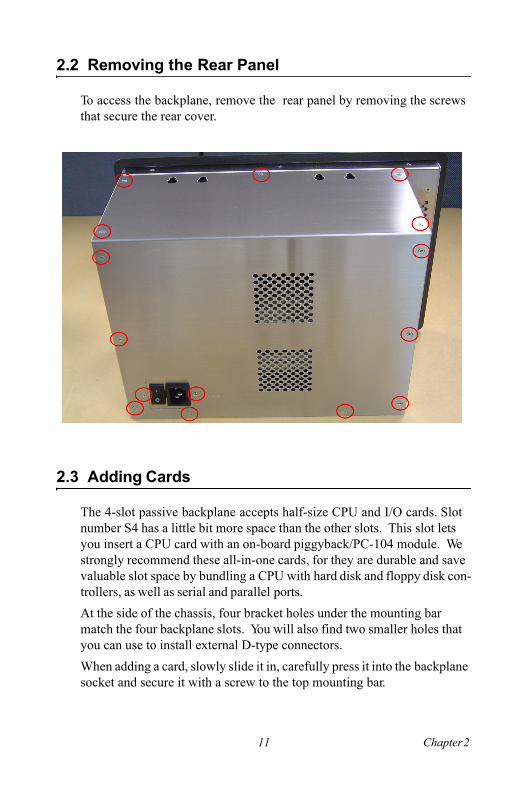
2.2 Removing the Rear Panel
To access the backplane, remove the rear panel by removing the screws that secure the rear cover.
2.3 Adding Cards
The 4-slot passive backplane accepts half-size CPU and I/O cards. Slot number S4 has a little bit more space than the other slots. This slot lets you insert a CPU card with an on-board piggyback/PC-104 module. We strongly recommend these all-in-one cards, for they are durable and save valuable slot space by bundling a CPU with hard disk and floppy disk con-trollers, as well as serial and parallel ports.At the side of the chassis, four bracket holes under the mounting bar match the four backplane slots. You will also find two smaller holes that you can use to install external D-type connectors.When adding a card, slowly slide it in, carefully press it into the backplane socket and secure it with a screw to the top mounting bar.
11 Chapter 2

2.4 Installing Optional Drives
The AWS-8124 offers space for two disk drives. When you receive the station, a 3½” floppy drive is already installed. Only the upper drive bay offers access through the floppy disk door. The lower position should therefore be reserved for an optional HDD. To install the optional drive, follow these instructions. 1. First remove the rear cover completely. 2. Unhook the five screws and take off the driver bay.
AWS-8124H User Manual 12

3. Insert the HDD into the bracket.
13 Chapter 2

4. Put the HDD bracket into the chassis and fasten the five screws. Then attach the HDD flat cable and power cable.
AWS-8124H User Manual 14

CH
AP
TE
R 3Maintenance
Sections Include:
• Passive Backplane• Power Supply and Cooling Fan• LCD Backlight
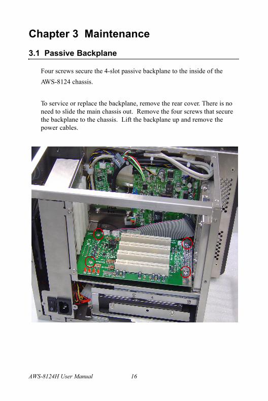
Chapter 3 Maintenance3.1 Passive Backplane
Four screws secure the 4-slot passive backplane to the inside of theAWS-8124 chassis.
To service or replace the backplane, remove the rear cover. There is no need to slide the main chassis out. Remove the four screws that secure the backplane to the chassis. Lift the backplane up and remove the power cables.
AWS-8124H User Manual 16

3.2 Power Supply and Cooling Fan
To service or replace the power supply and cooling fan, first remove the rear cover.To reach the power supply you must first remove the three screws and dis-connect the cable.
17 Chapter 3

To reach the fan you must first remove the power supply and then remove the four screws and disconnect the power cable.
Warning: Shut off all power to the AWS-8124 and unplug the power cables before you attempt to repair the power supply. For detailed power supply specifications refer to Appendix A.
3.3 LCD Backlight Replacement
In the normal working life of the AWS-8124 H you will seldom need to replace the LCD backlight. If it's necessary to maintain the LCD back-light, plaese contact your distributor, sales representative, or Advantech's customer service center.
AWS-8124H User Manual 18

AP
PE
ND
IX APower Supply Specifications
Sections Include:
• SNP-Z101 (AC 90~264V/60Hz/50Hz Input)
• D12-4081 (DC 12 V Input)• SNP-4081 (DC 24/48 V Input)

Appendix A Power Supply SpecsA.1 SNP- Z101 (AC 90 ~ 264V/ 60Hz/ 50Hz Input)
A.1.1 IntroductionThe SNP-Z101 is a 100-watt dual-output switching power supply. It is espe-cially designed for use with Network and Telecommunications Equip- ment.
A.1.2 Input SpecificationUniversal AC Input Voltage
The range of input voltage is from 90VAC to 264VAC
Input frequencyThe range of input frequency is between 47HZ to 63HZ.Input current
The maximum input current is 2A @ 115VAC / 1.0A @ 230VAC.
Inrush current
The inrush current Is less than 30A @ 115VACInput or 60A @ 230VAC input, cold start, at 25° C.
A.1.3 Output Specification
At the factory, the +5 V output is set between 5.03V to -0.2V at 60% rated load, and the +-12V output is checked to be within the specified volt-age accuracy range.Note: +12 V output voltage will track the adjustment.
Table A.1: Load Range
Output Min. load Rated load Max. load Accuracy range
+5V 0A 11.5A 15A -4.95V to +5.05V
+12V 0A 3A 5A -11.40V to 12.60V
-12V 0A 0.5A 0.5A -11.40V to 12.60V
AWS-8124H User Manual 20
Ripple and noiseThe peak to peak ripple and noise for each output is less than 1% of out-put voltage at rated load, which is measured by a 15 MHz bandwidth lim-ited oscilloscope and the each output is connected with 0.47 uF capacitor.
Line regulationThe line regulation Is less than ±0.5% at rated load with ±10%change In input voltage.
Load regulationThe load regulation for +5 V is less than ±1 %, for +12 V Is less than ±5 %, which are measured by changing the output load from+-40% to 60 % of the rated load, and the other output is kept at 60 % rated load.
Output powerThe max. power is 130W that works with 18CFM air forced cooling
A.1.4 General Features
EfficiencyThe efficiency is higher than 80 % while measuring at nominal line and rated load.
Hold up time
The hold up time is longer than 20 ms at 115 VAC input and rated load which is measured from the end of the last charging pulsc the when the main output drops down to 95% output voltage.
ProtectionOver voltage protectionThe built-in crowbar circuit will shut down the outputs to avoid damaging the external circuits. The trip point is around 5.7V to 7.0V for +5V out-put. The power supply will go into auto-recovery mode against short cir-cuit or over load conditions.
21 Appendix A

Short circuit protectionThe power supply will generate a hiccup mode to protect itself against short circuit or over load conditions, and will return to normal after wrong conditions are removed.
A.1.5 Environment SpecificationsOperating temperature:0º C to 50º C 100W with convection cool
130W with 18 CFM air Flow The air direction is from the side of PCB
Storage temperature: -40º C to 85º CHumidity: 5% to 95% (Non-condensing)
A.1.7 International StandardsSafety standards:UL 60950CSA 22.2 NO. 234VDE EN 60 950
EMI standards: Designed to meet the following limits FCCdocket 20780 curve “B” EN55022 “B”
EMS standards: Designed to meet the following standardsEN61000-4-26KV contact discharge, 8KV air discharge criteria AEN61000-4-310V/mcriteria AEN61000-4-42KV criteria AEN61000-4-63V criteria AEN61000-4-1130% dips 10ms criteria B
60% dips 100ms criteria C95% dips 5000ms criteria C
AWS-8124H User Manual 22