axial flow over a blunt circular cylinder with and without ... · journal of fluids and structures...
TRANSCRIPT

ARTICLE IN PRESS
0889-9746/$ - se
doi:10.1016/j.jfl
�CorrespondE-mail addr
Journal of Fluids and Structures 22 (2006) 949–959
www.elsevier.com/locate/jfs
Axial flow over a blunt circular cylinder with and withoutshear layer reattachment
H. Higuchia,�, P. van Langenb, H. Sawadac, C.E. Tinneya
aDepartment of Mechanical and Aerospace Engineering, Syracuse University, 141 Link Hall, Syracuse, NY 13244, USAbDepartment of Engineering Technology, University of Twente, Enschede, The Netherlands
cInstitute of Space Technology and Aeronautics, Japan Aerospace Exploration Agency, Tokyo 182, Japan
Received 19 October 2005; accepted 15 April 2006
Available online 28 July 2006
Abstract
Flow over a circular cylinder with its axis aligned with the free stream was investigated experimentally. Both
upstream and downstream faces of the cylinder are sharply truncated. The fineness ratio (length to diameter ratio) was
varied and the behavior of the leading-edge separating shear layer and its effect on the wake were studied in water using
both flow visualization and PIV techniques. For the moderately large fineness ratio, the shear layer reattaches with
subsequent boundary layer growth, whereas over a shorter cylinder the shear layer remains detached. This causes
differences in the wake recirculation region and the immediate wake patterns. The shear layer structure was analyzed
using the proper orthogonal decomposition (POD). The model in the water channel was sting-mounted and in some
cases the effect of model support was detected in the wake measurements. To avoid such disturbance from the model
support, an experiment was initiated in air using a magnetic model support and balance system. The drag variation with
fineness ratio is presented and discussed in light of the flowfield measurements.
r 2006 Elsevier Ltd. All rights reserved.
1. Introduction
There are several studies on flows over a blunt flat plate with the leading edge flow separation and subsequent
reattachment (Kiya and Sasaki, 1983; Sheridan et al., 1997; Mills et al., 2002). The latter two also investigated
interaction between the leading-edge shear layer and the trailing-edge vortex shedding as well as its control. However,
the axisymmetric counterpart, where a circular cylinder of a fixed length to diameter ratio (fineness ratio) is placed in an
axial flow has not achieved as much attention, in spite of its canonical configuration. In one flowfield study, Ota (1975)
used a combination of flow direction probe, hot wire and Pitot tube to measure the mean flowfield within the separation
bubble and in the boundary layer on a cylinder of fineness ratio 10. Kiya et al. (1991) used the split film, hot wire and
pressure transducer to probe the separation and reattaching flow. They found a cellular structure in the reattachment
region. The variation of the drag coefficient at various fineness ratios has been listed in many references [e.g., Blevins
(1984)], but they all date back to Eiffel’s early experiment conducted nearly 100 yrs ago. Therefore, to improve this
database a new experimental investigation was initiated jointly at Syracuse University and at Japan Aerospace
Exploration Agency (JAXA). Using the water channel and the PIV system at Syracuse, the flow structures of the
e front matter r 2006 Elsevier Ltd. All rights reserved.
uidstructs.2006.04.020
ing author. Tel.: +1315 443 4369; fax: +1 315 443 9099.
ess: [email protected] (H. Higuchi).

ARTICLE IN PRESSH. Higuchi et al. / Journal of Fluids and Structures 22 (2006) 949–959950
separating and reattaching shear layer and of the wake were studied. With its unique magnetic support and balance
system at JAXA, a data set of the drag coefficient at a wide range of fineness ratios was obtained. Robertson et al.
(1972) applied as high as 8% free-stream turbulence and observed significant reduction of drag due to reattachment of
separated shear layer over a short cylinder of fineness ratio 1.0. Koenig and Roshko (1985) placed a disk ahead of the
cylinder to control the separating shear layer and reattachment. The present variation of the fineness ratio and
associated shear layer phenomena are relevant for control of the wake and drag (Higuchi, 2005). The behavior and
structure of the separating shear layer are also critical for active control of the separated shear flows in these
axisymmetric bluff-bodies.
2. Hydrodynamic experiments
2.1. Experimental set up
For the experiment in water, a 0.6� 0.6� 2.44m water channel was used in conjunction with a DANTEC particle
image velocimetry (PIV) system in a two-component mode. The dual pulse Nd-Yag laser was rated 200mJ each.
Seeding was provided by 20 mm PSP particles uniformly mixed in the flow. The model diameter, D, was 77mm and the
Reynolds number based on the diameter and the free-stream velocity was varied between 10 000 and 30 000. Cylinders
of different lengths, L, were prepared to provide various fineness ratios, L/D. The test model was sting-mounted from
downstream to study the leading edge shear layer. The sting diameter was kept small (6.35mm) compared to the model
diameter. The streamlined cross-flow strut was also kept sufficiently far downstream. So the results are deemed
unaffected by the model support. Flow visualization was performed by injecting fluorescene dye from the leading edge
of the cylinder. For the wake measurement, the sting support was moved upstream. There was evidence of the
disturbance in a certain section of the wake as discussed later. Naturally the experiment with the magnetic support
system eliminated this.
2.2. Mean velocity field
The mean velocity field was obtained by ensemble-averaging the PIV data. Fig. 1 shows the mean velocity vector field
for a short model of the fineness ratio of 0.67. The leading-edge shear layer does not attach onto the cylinder forming a
large reverse flow region in the wake. At the fineness ratio of 1.5, the averaged shear layer reattaches to the trailing edge
of the cylinder as seen in the velocity vectors in Fig. 2(a). Fig. 2(b) shows the mean velocity profiles along a long cylinder
of L/D ¼ 3. The separating and reattaching shear layer and the recirculating flow within the separation bubble are
clearly seen in the measurement. The separation bubble is depicted in the mean streamline plot in Fig. 2(c). Even though
Ota (1975) used hot wire measurements on a rear-mounted cylindrical model and its use in the vicinity of this type of
separating flow may be questioned, the deduced streamlines and the location of the flow reattachment are in general
Fig. 1. Mean velocity field (PIV) and the model (L/D ¼ 0.67) at ReD ¼ 10 000.

ARTICLE IN PRESS
Fig. 2. Mean velocity profiles, ReD ¼ 10 000: (a) mean velocity above the L/D ¼ 1.5 cylinder; (b) mean velocity profiles L/D ¼ 3; (c)
mean streamline, L/D ¼ 3.
Fig. 3. Dye flow visualization, L/D ¼ 1.5.
H. Higuchi et al. / Journal of Fluids and Structures 22 (2006) 949–959 951
agreement with the current PIV measurement. As will be discussed later, this shear layer reattachment directly
influences the variation of drag on the cylinder with L/D.
2.3. Flow visualization and unsteady velocity field
The dye visualization in Fig. 3 presents an overview of the flow for L/D ¼ 1.5. The dye flow visualizations of
separating shear layers are shown in Fig. 4 for L/D ¼ 0.67, 1.5 and 3. Shear layer instability waves were clearly
identifiable in all cases, and the initial instability waves were nearly axisymmetric, while circumferential structure
develops prior to the reattachment. Snapshots of the instantaneous velocity vectors for these fineness ratios are given in
Fig. 5. In Figs. 4(b) and 5(b) at L/D ¼ 1.5, the separated shear layer is seen reattaching near the trailing edge of the
cylinder. The distance of the reattachment point for the L/D ¼ 3 case is similar to that for L/D ¼ 1.5.

ARTICLE IN PRESS
Fig. 5. Instantaneous velocity vectors over three cylinder models, ReD ¼ 10 000: (a) L/D ¼ 0.67; (b) L/D ¼ 1.5; (c) L/D ¼ 3.
Fig. 4. Dye flow visualizations, ReD ¼ 10 000: (a) L/D ¼ 0.67; (b) L/D ¼ 1.5; (c ) L/D ¼ 3.
H. Higuchi et al. / Journal of Fluids and Structures 22 (2006) 949–959952
ARTICLE IN PRESSH. Higuchi et al. / Journal of Fluids and Structures 22 (2006) 949–959 953
Even though the mean velocity profiles and mean streamlines of the separating and reattaching flow look well-
defined, it is worthwhile to note the complex flowfield involved. Fig. 5 show instantaneous velocity vector fields
obtained by the PIV measurements. They depict large scale, complex eddy motion. In particular, comparison of
Figs. 2(b) and 4(c) shows that while the averaged shear layer reattachment and the separation bubble with recircu-
lating flow region are well defined in the mean velocity, the instantaneous shear layer reattachment is far from well-
defined and is marked at any instant by the unsteady impingement of large vortical structures. Understanding these
structures will be pertinent in the control of the shear layer at wide Reynolds number range and free stream turbu-
lence levels. For example, wake control was performed by Higuchi et al. (2004) who conducted an active open-
loop control of a disk wake, the limiting case of small L/D with fully separated shear layer, and modified the size
of the recirculation zone in the wake with increased mean drag. Kiya et al. (1991) found two peaks in the surface
pressure spectra, one associated with the shear layer flapping and another associated with the vortex shedding in
the separating region. The present structure appears to be smaller in scale, but awaits for time-resolved PIV data
being collected.
The PIV measurement of the wake behind the sting-mounted model was also performed in water. The velocity
profiles below are taken on the streamwise cross-section normal to the plane of the strut to avoid possible direct effect of
the support. The velocity profile in the cross-flow plane will be discussed in a later section. When the wake flow was
measured with the sting placed upstream, a disturbance from the upstream support was detectable in the instantaneous
velocity field. Therefore, for accurate flowfield measurements in the wake a magnetically suspended model was deemed
of critical importance.
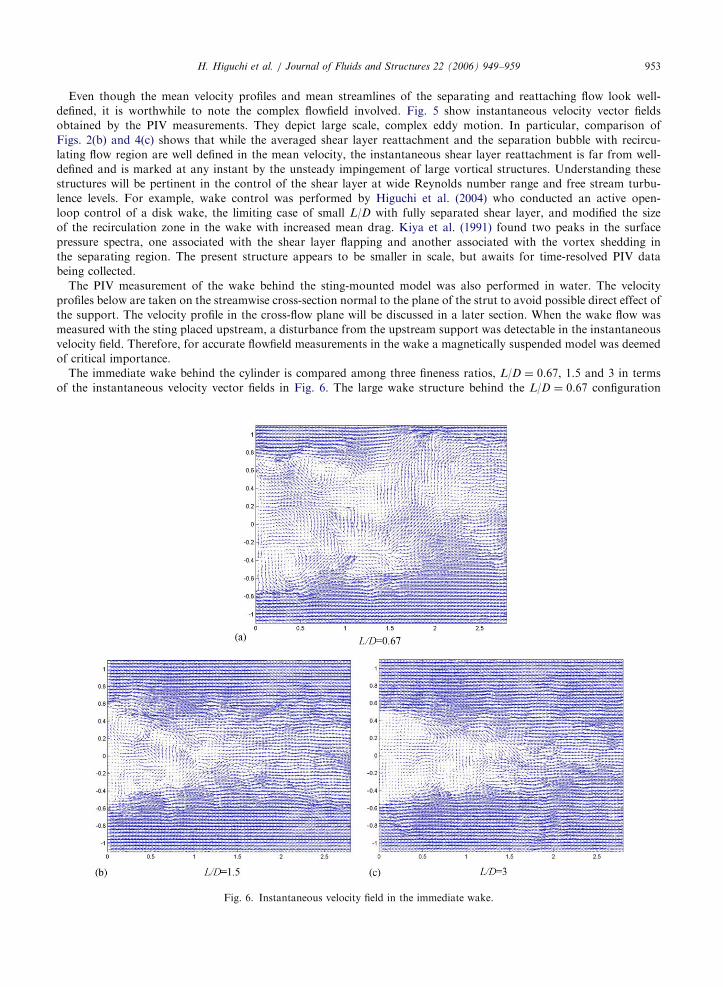
The immediate wake behind the cylinder is compared among three fineness ratios, L/D ¼ 0.67, 1.5 and 3 in terms
of the instantaneous velocity vector fields in Fig. 6. The large wake structure behind the L/D ¼ 0.67 configuration
Fig. 6. Instantaneous velocity field in the immediate wake.

ARTICLE IN PRESSH. Higuchi et al. / Journal of Fluids and Structures 22 (2006) 949–959954
reflects the separated, non-reattaching shear layer, while the more benign structure behind L/D ¼ 3 results from
the reattaching shear layer and subsequent boundary layer growth along the wall prior to the trailing edge separation.
The shedding frequency of trailing edge vortices behind a two-dimensional prism is known to vary in a step-wise
manner with the fineness ratio as summarized in Mills et al. (2002). These figures appear to indicate a higher frequency
helical structure at increased fineness ratio, but the wake warrants further investigation using time-resolved
measurements.
2.4. Propoer orthogonal decomposition of velocity data
The instantaneous velocity vector field data were analyzed using a ‘classical’ (POD) (Lumley, 1967; Delville et al.,
1998). In the POD analysis, the two-point spatial velocity correlation, Rijð~x; ~x0Þ ¼ uið~x; t0Þujð~x
0; t0Þ is used as a kernel of
the following integral equation:ZRijð~x; ~x
0ÞfðnÞj ð~x
0Þd~x0 ¼ lðnÞfðnÞi ð~xÞ,
where fðnÞi ð~xÞ is a nth POD mode eigenvector and l(n) is a nth mode POD eigenvalue.
The original velocity field can be partially or totally reconstructed by projecting the time dependent expansion
coefficient, an(t0), onto the eigenfunctions as
uð~x; t0Þ ¼XN
n¼1
anðt0ÞfðnÞi ð~x
0Þ,
where the time dependent expansion coefficient is obtained by projecting the PIV velocities onto the eigenfunctions,
anðt0Þ ¼
ZD
uið~x; t0ÞfðnÞi ð~xÞd~x.
The value of N determines how many modes are used to reconstruct the velocity field.
This ‘classical’ POD technique as well as ‘snapshot’ POD, the latter of which (first introduced by Sirovich (1987))
reduces the dimension of the eigenvalue problem for a large spatial grid size relative to the size of ensemble, has been
utilized for a feedback control of separated flow over an airfoil (Ausseur et al., 2005).
The instantaneous velocity fields for the L/D ¼ 1.5 and 3 cases are analyzed in Figs. 7 and 8, respectively. In both
cases, nearly 100% of total fluctuating energy was captured within first 10% of modes. Fig. 7(a) shows the energy
contained in each mode for L/D ¼ 1.5 case (similar distribution is found also for L/D ¼ 3). Figs. 7(b)–(d) and 8(b)–(d)
show the first three modes of the eigenfunctions. The shear layer curvature marking the reattachment in the first mode
and the mean vortex structure in the third mode are clearly seen. These modes can be used to reconstruct the low-
dimensional velocity field and a similar reconstruction of the instantaneous velocity field from this type of analysis has
been demonstrated for the separated flow over an airfoil (Glauser et al., 2004a, b).
The first mode for the L/D ¼ 3 case (Fig. 8(b)) indicates a similar structure as seen in the L/D ¼ 1.5 configuration.
Mode 3 contains a smaller vortical structure while mode 2 exhibits an alternating flow structure toward and away from
the wall. Thus, even the low-dimensional modes contain complicated coherent structures and understanding them may
be of practical use for controlling the flow reattachment.
The POD analysis was also applied to the velocity vector field in the wake in the cross-sectional plane normal to the
free stream. The first mode taken immediately behind the model supported from upstream showed the effect of the
strut, but the higher modes appear to recover the salient feature of the axisymmetric wake. Fig. 9(a) shows an example
of a non-axisymmetric mean velocity field that was affected by the strut, but the 3rd mode in Fig. 9(b) is devoid of direct
influence of the strut. These were obtained within the wake behind the L/D ¼ 0.67 cylinder. In the latter, the counter-
rotating longitudinal vortices are clearly seen. This may suggest this technique is useful for extracting coherent
structures embedded in contaminated data.
3. Experiment in air with magnetically suspended model
The study in the water channel presented above revealed the overall wake structure, the leading-edge shear layer and
its reattachment phenomena. However, the wake of a supporting strut was found to have influenced the cross-sectional
velocity profile downstream. This was evident when the POD analysis was made. While the 3rd or higher mode showed
the evenly distributed longitudinal structure, the 1st mode revealed the effect of the strut wake. Therefore, the parallel
experiment in air using the magnetically suspended model was initiated.

ARTICLE IN PRESS
Fig. 7. Proper Orthogonal Decomposition of velocity field over L/D ¼ 1.5 cylinder: (a) mean velocity; (b) 1st POD mode; (c) 2nd POD
mode; (d) 3rd POD mode.
H. Higuchi et al. / Journal of Fluids and Structures 22 (2006) 949–959 955
The blunt circular cylinder models were suspended magnetically to eliminate any disturbance from the conventional
model support. The Magnetic Support and Balance System was developed by Sawada and Kunimasu (2001) at (JAXA)
and was utilized in this experiment. The wind tunnel test-section measures 0.6� 0.6m, and equipped with 10
electromagnetic coils. Two CCD cameras monitor the model position and orientation. The feedback control system
secures the model fixed in space and at the same time measures the forces and moments acting on the model. The model

ARTICLE IN PRESS
Fig. 9. Mean and 3rd POD mode of the velocity field in the wake (including the strut) in the azimuthal plane; L/D ¼ 0.67 at X/D ¼ 3.
(Note redefined coordinates in this particular plot).
Fig. 8. Proper orthogonal decomposition of velocity field over L/D ¼ 3 cylinder: (a) mean velocity vector field; (b) 1st POD mode; (c)
2nd POD mode; (d) 3rd POD mode.
H. Higuchi et al. / Journal of Fluids and Structures 22 (2006) 949–959956
diameter was either 85 or 110mm for short cylinders. Fig. 10 is a photograph of a magnetically suspended cylinder in
the wind tunnel. The experimental detail is referred to Higuchi et al. (2005).
The flow symmetry and the absence of flow interference from the support are evident in the mean velocity profile
(Fig. 11) in the downstream wake. Here the mean velocity profile behind the long cylinder at L/D ¼ 5 was measured
sufficiently downstream of the recirculation region using a Pitot-static probe. As noted earlier, the velocity field in the
immediate wake is being surveyed with the PIV system and the results will be reported shortly. The various models were

ARTICLE IN PRESS
Fig. 10. Magnetically suspended cylinder model.
-85-85
-70
-70
-55
-55
-40
-40
-25
-25
-10
-10
5
5
20
20
35
35
50
50
65
65
80
80
y (mm)
z (m
m)
u/U
1.00 -1.02
0.98 -1.00
0.96 -0.98
0.94 -0.96
0.92 -0.94
0.90 -0.92
0.88 -0.90
0.86 -0.88
0.84 -0.86
0.82 -0.84
0.80 -0.82
Fig. 11. Mean velocity profile behind a magnetically suspended cylinder; L/D ¼ 5, X/D ¼ 6.
H. Higuchi et al. / Journal of Fluids and Structures 22 (2006) 949–959 957
constructed to form a wide range of the fineness ratio and the test results for short cylinders for L/Do4 are shown in
Fig. 12 for ReD ¼ 100 000. The experimental uncertainty is also noted. Fig. 12 also gives Eiffel’s wind tunnel data (1913)
and the corresponding Reynolds number is estimated to be 120 000. Eiffel noted the minimum drag to occur somewhere
between L/D ¼ 2.5 and 3. No uncertainty level is available for Eiffel’s classical data. Incidentally these data have been
quoted widely in literature. Though not included herein, Robertson et al. (1972) also gave the drag coefficient for the
disk, and for L/D ¼ 0.5, 1 and 2 with and without imposed free-stream turbulence. However, in addition to large
variations in their data, the drag coefficient appears to be excessively high even for a disk and warrants further
evaluation. In the present experiment, the Reynolds number dependency, if any, was not discernible within the
Reynolds number tested (6� 104–1.8� 105) even for larger L/Ds due to predominance of the pressure drag (Higuchi et
al., 2005). The minimum point of the drag coefficient corresponds to the region where the flow reattachment takes place
near the trailing edge of the cylinder (see Fig. 3). The subsequent rise in drag indicates a development of a turbulent
boundary layer downstream of the separation bubble. The oil flow visualization indicated the reattachment of the shear
layer after 1.3D downstream, in good agreement with this finding.
4. Concluding remarks
For both L/D ¼ 1.5 and 3 configurations, the separated leading edge shear layer reattached at approximately the
same location, as depicted in the ensemble-averaged velocity field and the mean streamlines. The instantaneous velocity
profiles showed large scale vortex motions well beyond the mean reattachment point. The mean closed separation
bubble actually consists of complex large-scale flow impinging on the surface in an unsteady manner. The large scale
turbulent structures were investigated using the proper orthogonal decomposition and the first few modes revealed the

ARTICLE IN PRESS
0.65
0.75
0.85
0.95
4321
L /D
CD
JAXA(85dia) 2004
JAXA(110dia) 2004
JAXA(110dia) 2005
Eiffel 1913
1.05
Fig. 12. Drag coefficient variation with fineness ratio.
H. Higuchi et al. / Journal of Fluids and Structures 22 (2006) 949–959958
essential features. When the fineness ratio is equivalent to the separation bubble length, this is close to the region where
the drag coefficient reaches its minimum. The motion of the immediate wake structure became suppressed as the
fineness ratio increased with reattached leading-edge shear layer. The size of the time-averaged recirculation region
at the blunt base of the cylinder decreased from the L/D ¼ 0.67 case to the L/D ¼ 1.5 case. The recirculation region for
L/D ¼ 3 was similar to that at L/D ¼ 1.5, which was somewhat reflected in the drag coefficient, and the vortex shedding
in the wake was significantly reduced. The particle image velocimetry has been set up with the magnetic suspension and
balance system and its results are expected to complement the present velocity measurement in water.
Acknowledgements
The second author (PVL) conducted a MS internship project at Syracuse University. The first and the third authors
(HH and HS) acknowledge the Grant-in-Aid for Scientific Research from the Japan Ministry of Education, Science and
Culture for the portion of their investigation utilizing the magnetic suspension system.
References
Ausseur, J.M., Pinier, J.T., Glauser, M.N., Higuchi, H., Carlson, H., 2005. Controller development for closed-loop feedback control of
flows. AIAA Paper 2005-5264, 35th AIAA Fluid Dynamics Conference and Exhibit, Toronto, Canada.
Blevins, R.D., 1984. Applied Fluid Dynamics Handbook. Van Nostrand Reinhold, New York.
Glauser, M., Young, M.J., Higuchi, H., Tinney, C.E., Carlson, H., 2004a. POD based experimental flow control on a NACA 4412
airfoil. AIAA-2004-0574, 42nd AIAA Aerospace Sciences Meeting & Exhibit, Reno, NV, USA.
Glauser, M., Higuchi, H., Ausseur, J., Pinier, J., 2004b. Feedback control of separated flows. AIAA Paper 2004-2521, 2nd AIAA Flow
Control Conference, Portland, OR, USA.
Higuchi, H., 2005. Passive and active control of three-dimensional wake of bluff-body. JSME International Journal, Series, B 48 (2),
322–327.
Higuchi, H., Ide, S., Qui, J., Tani, J., 2004. Open-loop control of the disk wake with electro-magnetic actuators. AIAA Paper 2004-
2321, 2nd AIAA Flow Control Conference, Portland, OR, USA.
Higuchi, H., Sawada, H., Van Langen, P., 2005. Flow over a magnetically suspended cylinder in an axial free stream. AIAA Paper
2005-1078, the 43rd AIAA Aerospace Sciences Meeting, Reno, NV, USA.

ARTICLE IN PRESSH. Higuchi et al. / Journal of Fluids and Structures 22 (2006) 949–959 959
Kiya, M., Sasaki, K., 1983. Structure of a turbulent separation bubble. Journal of Fluid Mechanics 137, 83–113.
Kiya, M., Mochizuki, O., Tamura, H., Ishikawa, R., Kushioka, K., 1991. Turbulence properties of an axisymmetric separation-and-
reattaching flow. AIAA Journal 29 (6), 936–941.
Koenig, K., Roshko, A., 1985. An experimental study of geometrical effects on the drag and flow field of two bluff bodies separated by
a gap. Journal of Fluid Mechanics 156, 167–204.
Mills, R., Sheridan, J., Hourigan, K., 2002. Response of base suction and vortex shedding from rectangular prisms to transverse
forcing. Journal of Fluid Mechanics 461, 25–49.
Ota, T., 1975. An axisymmetric separated and reattached flow on a longitudinal blunt circular cylinder. Journal of Applied Mechanics,
(June), 311–315.
Robertson, J.A., Lin, C.Y., Rutherford, G.S., Stine, M.D., 1972. Turbulence effects on drag of sharp-edged bodies. ASCE Journal of
the Hydraulic Division, 1187–1209.
Sawada, H., Kunimasu, T., 2001. Status of MSBS Study at NAL. Sixth International Symposium on Magnetic Suspension
Technology, Turin, Italy, pp.163–168.
Sheridan, J., Hourigan, K., Mills, R., 1997. Vortex structures in flow over a rectangular plate. ASME97-FSI, ASME Meeting, Dallas,
TX, USA.
Sirovich, L., 1987. Turbulence and the dynamics of coherent structures. Part I: Coherent structures. Quarterly of Applied Mathematics
XLV (3), 561–571.