axxrsbbu8 user guide - intel.com€¦ · intel® raid smart battery axxrsbbu8 user’s guide vii...
TRANSCRIPT
Intel® RAID Smart Battery AXXRSBBU8 User’s Guide
A Guide for Technically Qualified Assemblers of Intel® Identified Subassemblies/Products
Intel Order Number: G15580-003
Warranty Notice: Adding a battery onto an Intel® RAID controller will limit the warranty of this product. Returns determined to be caused by battery installation damage, stripped screws, or other damage resulting from the battery installation will not be covered. ESD damage to the board will also not be covered by the warranty.
The warranty on the Intel® RAID Smart Battery AXXRSBBU8 is one year.
Disclaimer
Information in this document is provided in connection with Intel® products. No license, express or implied, by estoppel or otherwise, to any intellectual property rights is granted by this document. Except as provided in Intel's Terms and Conditions of Sale for such products, Intel® assumes no liability whatsoever, and Intel® disclaims any express or implied warranty, relating to sale and/or use of Intel® products including liability or warranties relating to fitness for a particular purpose, merchantability, or infringement of any patent, copyright or other intellectual property right. Intel® products are not designed, intended or authorized for use in any medical, life saving, or life sustaining applications or for any other application in which the failure of the Intel® product could create a situation where personal injury or death may occur. Intel® may make changes to specifications and product descriptions at any time, without notice.
Intel is a registered trademark of Intel Corporation or its subsidiaries in the United States and other countries.
* Other names and brands may be claimed as the property of others.
Copyright © 2011 Intel Corporation. All rights reserved.
Copyright © 2007 - 2011 LSI Corporation. All rights reserved.
ii Intel® RAID Smart Battery AXXRSBBU8 User’s Guide
Safety Information
Important Safety Instructions
Read all caution and safety statements in this document before performing any of the instructions. See also Intel Server Boards and Server Chassis Safety Information on the Intel® Server Deployment Toolkit 2.0 CD and/or at http://www.intel.com/support/motherboards/server/sb/cs-010770.htm.
Wichtige Sicherheitshinweise
Lesen Sie zunächst sämtliche Warn- und Sicherheitshinweise in diesem Dokument, bevor Sie eine der Anweisungen ausführen. Beachten Sie hierzu auch die Sicherheitshinweise zu Intel-Serverplatinen und Servergehäusen auf der Intel® Server Deployment Toolkit 2.0 CD oder unter http://www.intel.com/support/motherboards/server/sb/cs-010770.htm.
Consignes de sécurité
Lisez attention toutes les consignes de sécurité et les mises en garde indiquées dans ce document avant de suivre toute instruction. Consultez Intel Server Boards and Server Chassis Safety Information sur le Intel® Server Deployment Toolkit 2.0 CD ou bien rendez-vous sur le site http://www.intel.com/support/motherboards/server/sb/cs-010770.htm.
Instrucciones de seguridad importantes
Lea todas las declaraciones de seguridad y precaución de este documento antes de realizar cualquiera de las instrucciones. Vea Intel Server Boards and Server Chassis Safety Information en el Intel® Server Deployment Toolkit 2.0 CD y/o en http://www.intel.com/support/motherboards/server/sb/cs-010770.htm.
Intel® RAID Smart Battery AXXRSBBU8 User’s Guide iii

iv Intel® RAID Smart Battery AXXRSBBU8 User’s Guide
Warnings
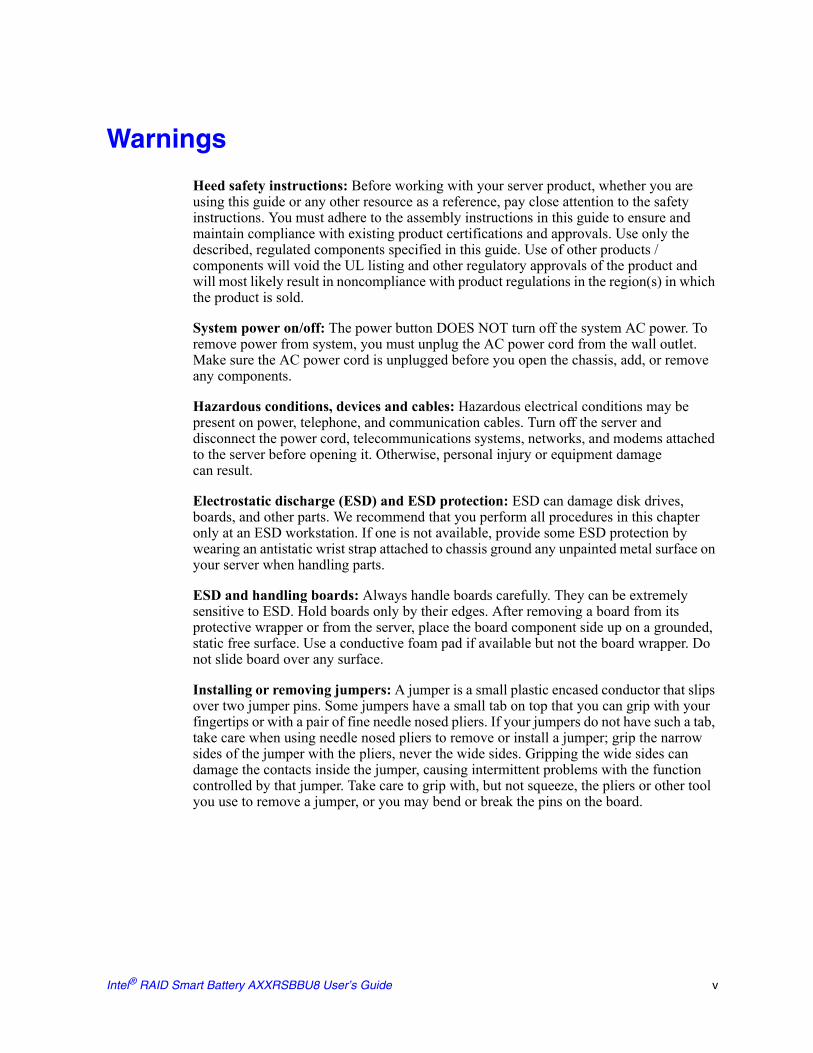
Heed safety instructions: Before working with your server product, whether you are using this guide or any other resource as a reference, pay close attention to the safety instructions. You must adhere to the assembly instructions in this guide to ensure and maintain compliance with existing product certifications and approvals. Use only the described, regulated components specified in this guide. Use of other products / components will void the UL listing and other regulatory approvals of the product and will most likely result in noncompliance with product regulations in the region(s) in which the product is sold.
System power on/off: The power button DOES NOT turn off the system AC power. To remove power from system, you must unplug the AC power cord from the wall outlet. Make sure the AC power cord is unplugged before you open the chassis, add, or remove any components.
Hazardous conditions, devices and cables: Hazardous electrical conditions may be present on power, telephone, and communication cables. Turn off the server and disconnect the power cord, telecommunications systems, networks, and modems attached to the server before opening it. Otherwise, personal injury or equipment damagecan result.
Electrostatic discharge (ESD) and ESD protection: ESD can damage disk drives, boards, and other parts. We recommend that you perform all procedures in this chapter only at an ESD workstation. If one is not available, provide some ESD protection by wearing an antistatic wrist strap attached to chassis ground any unpainted metal surface on your server when handling parts.
ESD and handling boards: Always handle boards carefully. They can be extremely sensitive to ESD. Hold boards only by their edges. After removing a board from its protective wrapper or from the server, place the board component side up on a grounded, static free surface. Use a conductive foam pad if available but not the board wrapper. Do not slide board over any surface.
Installing or removing jumpers: A jumper is a small plastic encased conductor that slips over two jumper pins. Some jumpers have a small tab on top that you can grip with your fingertips or with a pair of fine needle nosed pliers. If your jumpers do not have such a tab, take care when using needle nosed pliers to remove or install a jumper; grip the narrow sides of the jumper with the pliers, never the wide sides. Gripping the wide sides can damage the contacts inside the jumper, causing intermittent problems with the function controlled by that jumper. Take care to grip with, but not squeeze, the pliers or other tool you use to remove a jumper, or you may bend or break the pins on the board.
Intel® RAID Smart Battery AXXRSBBU8 User’s Guide v

vi Intel® RAID Smart Battery AXXRSBBU8 User’s Guide

Table of Contents
Safety Information ..................................................................................................... iiiImportant Safety Instructions ................................................................................................ iiiWichtige Sicherheitshinweise ............................................................................................... iiiConsignes de sécurité .......................................................................................................... iiiInstrucciones de seguridad importantes ............................................................................... iiiWarnings ................................................................................................................................ v
Chapter 1: About the Intel® RAID Smart Battery AXXRSBBU8 .............................. 1
Chapter 2: Installing the Hardware ........................................................................... 3Remote Extender Board (REB) .............................................................................................4Remote Battery Connecting Cables ......................................................................................4Important Pre-installation Considerations ..............................................................................5Installing the Intel® RAID Smart Battery AXXRSBBU8 .........................................................6
Removing the RAID Controller ......................................................................................6Installing the Intel® RAID Smart Battery AXXRSBBU8 .................................................6Connecting the Plastic Battery Holder to the Chassis .................................................11Attaching the Connecting Cable to the Server System ...............................................14Installing the Intel® RAID Controller in the Server System ..........................................14
Chapter 3: Monitoring Battery Backup ................................................................... 17Monitoring the BBU with the Intel® RAID BIOS Configuration Utility ..................................17Using Intel® RAID Web Console 2 ......................................................................................18
Chapter 4: Replacing Battery Backup Units .......................................................... 21Disposing of Battery Backup Units ......................................................................................21
Chapter 5: Battery Backup Unit Specifications ..................................................... 23Battery Life and Data Retention Time ..................................................................................23
Intel® RAID Smart Battery AXXRSBBU8 User’s Guide vii

viii Intel® RAID Smart Battery AXXRSBBU8 User’s Guide

List of Figures
Figure 1. Top and Bottom View of the Intel® RAID Smart Battery AXXRSBBU8...................... 3Figure 2. Remote Extender Board............................................................................................. 4Figure 3. Installing Directly on the Intel® RAID Controller......................................................... 7Figure 4. Mounting the Battery on a RAID Controller................................................................ 8Figure 5. Installing the Plastic Standoff on the REB.................................................................. 9Figure 6. Installing the REB onto the RAID Controller ............................................................ 10Figure 7. Connecting the Cables............................................................................................. 11Figure 8. Aligning Holder’s Tabs to the Chassis Clips ............................................................ 12Figure 9. Engaging Plastic Battery Holder Tabs with the Chassis Clips ................................. 13Figure 10. Engaging Holder Tabs with the Chassis Clips ....................................................... 14Figure 11. Seating the RAID Card into PCI Express* Slot ...................................................... 15Figure 12. Monitoring the Battery with Intel® RAID BIOS Console ......................................... 18Figure 13. BBU information in Intel® RAID Web Console 2 .................................................... 19
Intel® RAID Smart Battery AXXRSBBU8 User’s Guide ix

x Intel® RAID Smart Battery AXXRSBBU8 User’s Guide

List of Tables
Table 1. Cable Compatability ....................................................................................................5Table 2. BBU Specifications ....................................................................................................23
Intel® RAID Smart Battery AXXRSBBU8 User’s Guide xi

xii Intel® RAID Smart Battery AXXRSBBU8 User’s Guide

1 About the Intel® RAID Smart Battery AXXRSBBU8
Intel® RAID (Redundant Array of Inexpensive Disks) Controllers and Intel® Integrated RAID Modules provide reliability, high performance, and fault-tolerant disk subsystem management. A complete fault-tolerant strategy requires protection of all data, including the unwritten cached data in the RAM cache. If power is lost, the data in the RAM cache is lost. To avoid data loss, a battery can be added to supply power to the RAID RAM during an AC power outage or if the AC power cord is removed.
A battery backup unit (BBU) protects the integrity of the cached data on Intel® RAID Controllers by providing backup power if there is a complete AC power failure or a brief power outage. The Intel® RAID Smart Battery Backup Unit provides an inexpensive alternative to using an uninterruptible power supply (UPS) or it can act as a second level of fault tolerance when used with a UPS.
The cache memory available on Intel® RAID controllers can improve the overall system performance. Writing data to the controller's cache memory is much faster than writing it to a storage device. Write operations appear to complete very quickly at the software application level. The Intel® RAID Controller writes the cached data to the storage device when system activity is low or when the cache is getting full. The risk of using write-back cache is that the cached data can be lost if the AC power fails before it is written to the storage device. This risk factor is eliminated when the Intel® RAID Controller has aBBU installed.
The Intel® RAID Smart Battery Backup Unit monitors the voltage level of the DRAM modules installed on the Intel® RAID Controller. If the voltage drops below a predefined level, the battery backup module switches the memory power source from the controller to the battery pack attached to the Intel® RAID Smart Battery Backup Unit. As long as the voltage level stays below the predefined value, the battery backup module provides power for memory. When the voltage level returns to an acceptable level, the module switches the power source back to the Intel® RAID Controller, and all pending writes to storage devices are completed without losing any data.
The battery backup module has built-in functionality to charge the battery pack automatically and to communicate battery status information such as voltage, temperature, and current to the host computer system.
The Intel® RAID Smart Battery AXXRSBBU8 is a smart battery backup module and uses lithium-ion (Li-Ion) battery technology. It is compatible with a backup auxiliary power source. The battery is charged automatically.
Intel® RAID Smart Battery AXXRSBBU8 User’s Guide 1

2 Intel® RAID Smart Battery AXXRSBBU8 User’s Guide
2 Installing the Hardware
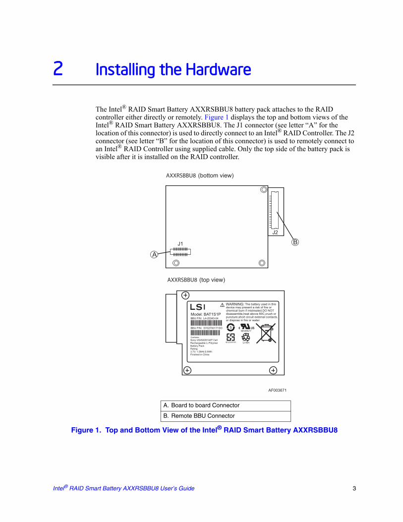
The Intel® RAID Smart Battery AXXRSBBU8 battery pack attaches to the RAID controller either directly or remotely. Figure 1 displays the top and bottom views of the Intel® RAID Smart Battery AXXRSBBU8. The J1 connector (see letter “A” for the location of this connector) is used to directly connect to an Intel® RAID Controller. The J2 connector (see letter “B” for the location of this connector) is used to remotely connect to an Intel® RAID Controller using supplied cable. Only the top side of the battery pack is visible after it is installed on the RAID controller.
Figure 1. Top and Bottom View of the Intel® RAID Smart Battery AXXRSBBU8
AXXRSBBU8 (bottom view)
AXXRSBBU8 (top view)
J1
J2
B
A
AF003671
A. Board to board Connector
B. Remote BBU Connector
Intel® RAID Smart Battery AXXRSBBU8 User’s Guide 3
Remote Extender Board (REB)
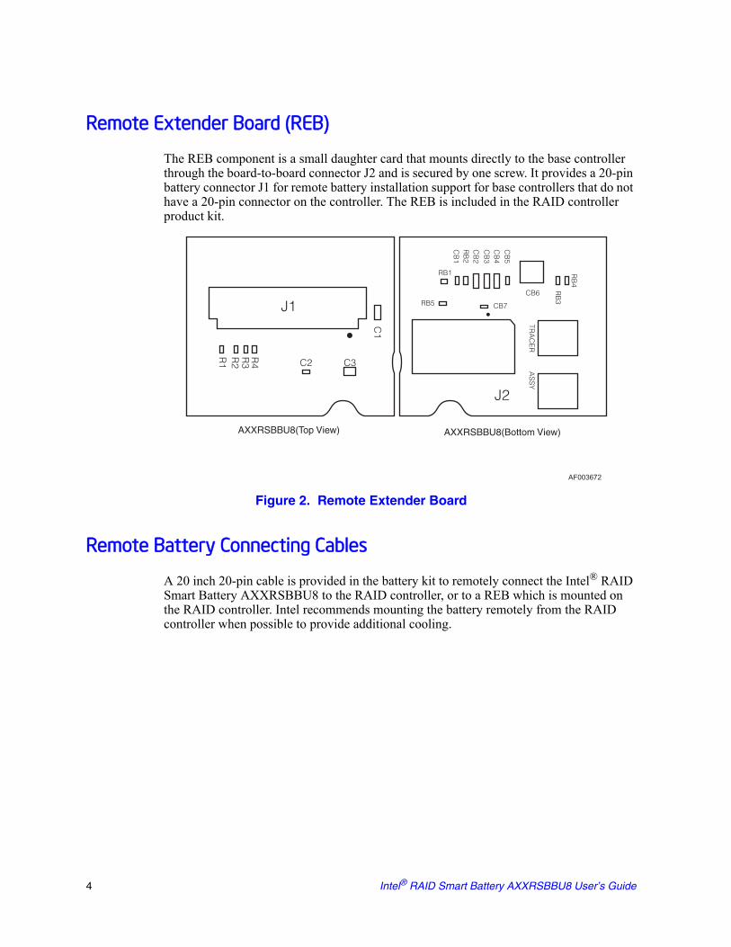
The REB component is a small daughter card that mounts directly to the base controller through the board-to-board connector J2 and is secured by one screw. It provides a 20-pin battery connector J1 for remote battery installation support for base controllers that do not have a 20-pin connector on the controller. The REB is included in the RAID controller product kit.
Figure 2. Remote Extender Board
Remote Battery Connecting Cables
A 20 inch 20-pin cable is provided in the battery kit to remotely connect the Intel® RAID Smart Battery AXXRSBBU8 to the RAID controller, or to a REB which is mounted on the RAID controller. Intel recommends mounting the battery remotely from the RAID controller when possible to provide additional cooling.
AF003672
J1
J2
C1
CB
1R
B2
RB
3
RB
4
RB1
RB5 CB7
CB6
CB
2
CB
3C
B4
CB
5
C2 C3
R4
R3
R2
R1
TRA
CE
RA
SS
Y
AXXRSBBU8(Top View) AXXRSBBU8(Bottom View)
4 Intel® RAID Smart Battery AXXRSBBU8 User’s Guide

Table 1. Cable Compatability
Note: Controllers that can directly connect to 20-inch cable already has a cable connector on it, which is same as the J1 connector as shown in Figure 2 (Remote Extender Board).
Important Pre-installation Considerations
Warning: Always ground yourself and/or use a ground strap before touching the RAID controller or the Intel® RAID Smart Battery AXXRSBBU8. Perform all installation work at an ESD-safe workstation. Use an ESD-safe Phillips* screwdriver set to a maximum torque of 2.25 inch-pounds, and be sure the screwdriver is centered in the screw to avoid damaging the screw head. If you exceed the maximum torque specification, you may damage the board, connectors, or screws, and you will void the warranty of the board.
The batteries in the Intel® RAID Smart Battery AXXRSBBU8 must charge for at least six hours during fast charge, under normal operating conditions.
To protect your data, Intel recommends that you set the RAID Controller Write Policy to write-through until the battery unit is fully charged. When the battery unit is charged, you can change the Write Policy to write-back to take advantage of the performance improvements of data caching.
The maximum ambient temperature for the battery pack is shown in the following tables.
Intel® RAID Controller or Server System 20-inch Cable
Intel® RAID Controller RS2BL080 and RSBL080DE
X (Requires the REB)
Intel® RAID Controller RS2BL040 X (Requires the REB)
Intel® RAID Controller RS2PI008 and RS2PI008DE
X (Direct connection with controller without REB)
Intel® RAID Controller RS2MB044 X (Direct connection with controller without REB)
Intel(R) RAID Controller RS2SG244 X (Direct connection with controller without REB)
Intel(R) RAID Controller RS2WG160 X (Direct connection with controller without REB)
AXXRSBBU8 Operating temperature of 55°C
Expected hold time 48 hours 12 hours
Service life Up to 1 year Up to 3 years
AXXRSBBU8 Operating temperature of 45°C
Expected hold time 48 hours 12 hours
Service life Up to 3 years Up to 5 years
Intel® RAID Smart Battery AXXRSBBU8 User’s Guide 5
Note: The temperature of the battery pack is generally 15-20 degrees higher than the ambient temperature during fast charge. Therefore, to complete the fast charge cycle, ambient temperature should be less than 55° C. If the ambient temperature exceeds 45° C, the fast charge cycle will terminate prematurely, thus preventing the battery pack from reaching a fully charged state. Intel recommends mounting the battery remotely from the RAID controller when possible to provide additional cooling.
Installing the Intel® RAID Smart Battery AXXRSBBU8
To install the Intel® RAID Smart Battery AXXRSBBU8 on the Intel® RAID Controller, you must perform the following steps: 1. Remove the RAID Controller if it is already installed in the server system. For
information, see “Removing the RAID Controller” on page 6.2. Install the Intel® RAID Smart Battery AXXRSBBU8 on the RAID Controller using
one of the following methods:— Install directly through the board-to-board connector. For information, see
“Installing Directly on the RAID Controller” on page 7.— Set up a remote connection through the remote BBU connector. For information,
see “Setting up a Remote Connection to the RAID Controller” on page 9.3. Install the RAID Controller in the server system. For information, see “Installing the
Intel® RAID Controller in the Server System” on page 14.
Removing the RAID Controller
If the RAID controller is already installed in a computer, do the following to remove it before you install the Intel® RAID Smart Battery AXXRSBBU8: 1. Shut down the computer, turn off the power, and unplug the power cord(s). 2. Remove the chassis cover and ground yourself before touching the RAID controller.
Carefully unplug all cables connected to the RAID controller. Press the silver spring at the connector end of the data cables to make sure the two tiny catches release.
3. Carefully remove the RAID controller from the server board. For more information on removing add-in cards, refer to the server board documentation.
4. Place the RAID controller on a flat, clean, static-free surface.
Installing the Intel® RAID Smart Battery AXXRSBBU8
You can either directly connect the Intel® RAID Smart Battery AXXRSBBU8 to the RAID Controller or you can set up a remote connection to the RAID Controller.
6 Intel® RAID Smart Battery AXXRSBBU8 User’s Guide

Installing Directly on the RAID Controller
To install the Intel® RAID Smart Battery AXXRSBBU8 on the RAID Controller through the J2 board-to-board connector (daughter card), do the following:1. Ground yourself, and remove the Intel® RAID Smart Battery AXXRSBBU8 from the
package.2. Make sure the three screws, and Phillips* screwdriver are easily accessible during the
following steps.3. Remove the protective metal cover from the battery connector on the Intel® RAID
Controller.4. Align the battery for your specific RAID controller by placing the Intel® RAID
Controller with the components facing up (see Figure 3).
Figure 3. Installing Directly on the Intel® RAID Controller
5. Hold the controller such that the battery side is up and the three screw holes are aligned.
6. Carefully press the Intel® RAID Smart Battery AXXRSBBU8 onto the RAID controller, so that the two connectors shown above in Figure 6 are firmly joined
AF003673
BatteryA
B
Intel® RAID Smart Battery AXXRSBBU8 User’s Guide 7
.
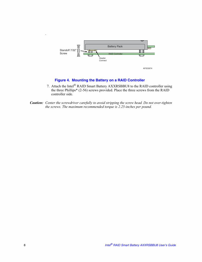
Figure 4. Mounting the Battery on a RAID Controller
7. Attach the Intel® RAID Smart Battery AXXRSBBU8 to the RAID controller using the three Phillips* (2-56) screws provided. Place the three screws from the RAID controller side.
Caution: Center the screwdriver carefully to avoid stripping the screw head. Do not over-tighten the screws. The maximum recommended torque is 2.25-inches per pound.
AF003674
Standoff 7/32’’Screw
Battery Pack
RAID Controller
HeaderConnect
8 Intel® RAID Smart Battery AXXRSBBU8 User’s Guide

Setting up a Remote Connection to the RAID Controller
To install the Intel® RAID Smart Battery AXXRSBBU8 on the RAID Controller through the J2 Remote BBU connector, do the following:. 1. Ground yourself, and remove the Intel® RAID Smart Battery AXXRSBBU8 from the
package.2. Install the plastic standoff to the REB.
Figure 5. Installing the Plastic Standoff on the REB
3. Install the Remote Extension Board (REB) onto the RAID controller’s battery connector (JT3 on the RS2BL080).
AF003238
A
Intel® RAID Smart Battery AXXRSBBU8 User’s Guide 9

Figure 6. Installing the REB onto the RAID Controller
4. Verify that the wire from the battery is connected to the circuit board. If it is not connected, insert the battery pack harness connector at the end of the colored wires into the 5-pin J4 connector (see letter “A” in Figure 1) on the back side of the battery.
AF003239
A
B
10 Intel® RAID Smart Battery AXXRSBBU8 User’s Guide
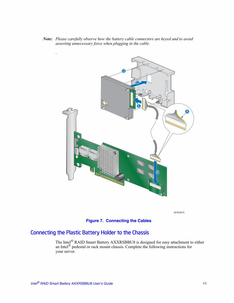
Note: Please carefully observe how the battery cable connectors are keyed and to avoid asserting unnecessary force when plugging in the cable.
.
Figure 7. Connecting the Cables
Connecting the Plastic Battery Holder to the Chassis
The Intel® RAID Smart Battery AXXRSBBU8 is designed for easy attachment to either an Intel® pedestal or rack mount chassis. Complete the following instructions foryour server.
AF003675
A
B
C
D
E
Intel® RAID Smart Battery AXXRSBBU8 User’s Guide 11

If you are installing this component into a third-party chassis, you must first install an attachment mechanism, such as industrial-grade Velcro*. Refer to your server chassis documentation or discuss an appropriate attachment mechanism with your server chassis manufacturer to ensure the attachment mechanism complies with the chassis requirements.
Intel® Server Chassis SC5400, Intel® Server Chassis SC5600, Intel® Server Chassis SC5650, Intel® Server Systems SR1600UR, SR1625UR, SR2600UR, and SR2625UR
1. Locate the installation clips inside the chassis. They are on the left side of the chassis, near the rear. Remove the mylar pad if there is a mylar pad covering the mounting hole.
2. Align the tabs on the plastic battery holder with the clips on the chassis (Figure 8).
Figure 8. Aligning Holder’s Tabs to the Chassis Clips
3. Slide the plastic battery holder toward the front of the system until the tabs engage with the clips in the chassis (Figure 9).
AF003676
12 Intel® RAID Smart Battery AXXRSBBU8 User’s Guide
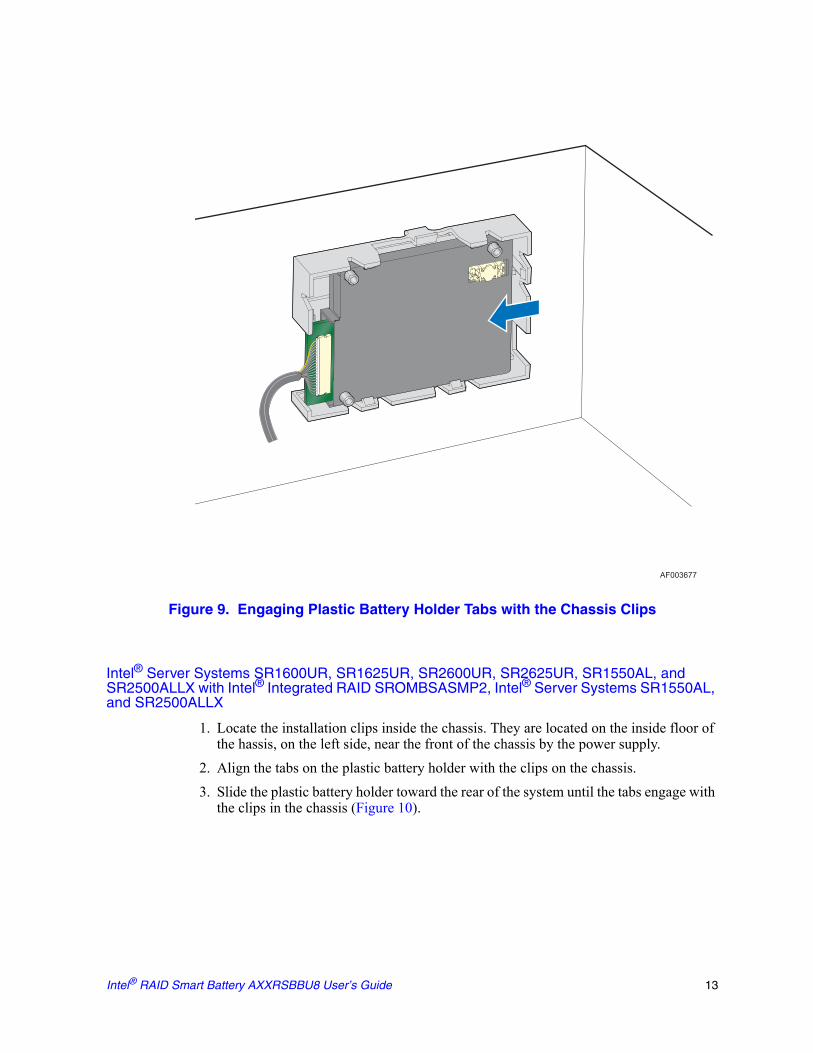
Figure 9. Engaging Plastic Battery Holder Tabs with the Chassis Clips
Intel® Server Systems SR1600UR, SR1625UR, SR2600UR, SR2625UR, SR1550AL, and SR2500ALLX with Intel® Integrated RAID SROMBSASMP2, Intel® Server Systems SR1550AL, and SR2500ALLX
1. Locate the installation clips inside the chassis. They are located on the inside floor of the hassis, on the left side, near the front of the chassis by the power supply.
2. Align the tabs on the plastic battery holder with the clips on the chassis. 3. Slide the plastic battery holder toward the rear of the system until the tabs engage with
the clips in the chassis (Figure 10).
AF003677
Intel® RAID Smart Battery AXXRSBBU8 User’s Guide 13
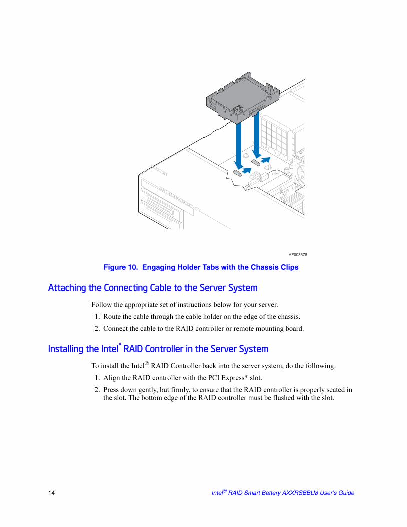
Figure 10. Engaging Holder Tabs with the Chassis Clips
Attaching the Connecting Cable to the Server System
Follow the appropriate set of instructions below for your server.1. Route the cable through the cable holder on the edge of the chassis.2. Connect the cable to the RAID controller or remote mounting board.
Installing the Intel® RAID Controller in the Server System
To install the Intel® RAID Controller back into the server system, do the following:1. Align the RAID controller with the PCI Express* slot. 2. Press down gently, but firmly, to ensure that the RAID controller is properly seated in
the slot. The bottom edge of the RAID controller must be flushed with the slot.
AF003678
14 Intel® RAID Smart Battery AXXRSBBU8 User’s Guide

Figure 11. Seating the RAID Card into PCI Express* Slot
Caution: Never apply pressure to the Intel® RAID Smart Battery AXXRSBBU8 when you insert the RAID controller. Only press down on the top edge of the RAID controller. 3. Attach the cables, as needed, to the connectors on the Intel® RAID controller. 4. Replace the chassis cover and reattach the power cord(s).
AF003679
Battery
Intel® RAID Smart Battery AXXRSBBU8 User’s Guide 15

16 Intel® RAID Smart Battery AXXRSBBU8 User’s Guide
3 Monitoring Battery Backup
Multiple utilities are available to display and configure the BBU information, including the recharge count. When you replace a BBU, you should reset this counter to zero. Intel recommends that you replace the BBU once a year or after 500 recharge cycles, whichever comes first.
Note: This chapter describes only the BBU-related features of the utility programs. For complete information on these utilities, see the Intel® RAID Software User's Guide.
Monitoring the BBU with the Intel® RAID BIOS Configuration Utility
The Intel® RAID BIOS Console can be used to configure disk arrays and logical drives. It is independent of the operating system and can be accessed at server start up by pressing <Ctrl>+<G>.
To view the BBU information, do the following:1. At boot, press <Ctrl> + <G> when prompted.2. Once the Intel® RAID BIOS Console loads and the main menu appears, choose
Adapter Properties.3. Click Next to view the second Adapter Properties screen. 4. In the Battery Backup field at the top left of the Adapter Properties screen, click
Present. 5. The Battery Module screen appears, as shown in Figure 12. This screen contains the
following information:— Battery information— Design information— Capacity information— Auto Learn properties and settings
Intel® RAID Smart Battery AXXRSBBU8 User’s Guide 17
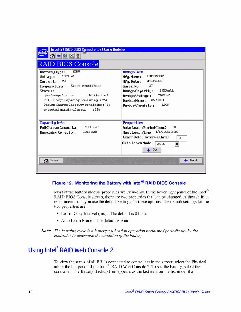
Figure 12. Monitoring the Battery with Intel® RAID BIOS Console
Most of the battery module properties are view-only. In the lower right panel of the Intel® RAID BIOS Console screen, there are two properties that can be changed. Although Intel recommends that you use the default settings for these options. The default settings for the two properties are:
• Learn Delay Interval (hrs) - The default is 0 hour.• Auto Learn Mode - The default is Auto.
Note: The learning cycle is a battery calibration operation performed periodically by the controller to determine the condition of the battery.
Using Intel® RAID Web Console 2
To view the status of all BBUs connected to controllers in the server, select the Physical tab in the left panel of the Intel® RAID Web Console 2. To see the battery, select the controller. The Battery Backup Unit appears as the last item on the list under that
18 Intel® RAID Smart Battery AXXRSBBU8 User’s Guide

controller (see Figure 13). An icon (small rectangle or red dot) appears in the left pane to indicate the BBU status. The rectangle indicates normal operation; a red dot indicates the BBU has failed.
Figure 13. BBU information in Intel® RAID Web Console 2
The Battery Backup Unit properties include: • The number of times the BBU has been recharged (Cycle Count).• The full capacity of the BBU, percentage of the current charge, and the estimated time
until the charge will be depleted.• The BBU temperature, voltage, current, and remaining capacity.• The estimated time until the battery is fully charged if the battery is currently
charging.
Learn cycle is a battery calibration operation performed by the controller periodically to determine the condition of the battery. You can start battery learn cycles manually or automatically. To choose automatic battery learn cycles, enable automatic learn cycles. To choose manual battery learn cycles, disable automatic learn cycles.
If you enable automatic learn cycles, you can delay the start of the learn cycles for up to 168 hours (7 days). If you disable automatic learn cycles, you can start the learn cycles manually, and you can choose to receive a reminder to start a manual learn cycle.
Intel® RAID Smart Battery AXXRSBBU8 User’s Guide 19

20 Intel® RAID Smart Battery AXXRSBBU8 User’s Guide

4 Replacing Battery Backup Units
Intel recommends that you replace each BBU once in one year or after 500 recharging cycles, whichever comes first. The battery pack has one year warranty. After you install a new BBU, use one of the Intel configuration utilities to reset the battery recharge cycle counter to zero. For instructions, see “Monitoring the BBU with the Intel® RAID BIOS Configuration Utility” on page 17.
Disposing of Battery Backup Units
Warning: Do not damage the battery pack in any way. Toxic chemicals can be released if it is damaged.
The material in the battery pack contains heavy metals that can contaminate the environment. Federal, state, and local regulations prohibit the disposal of rechargeable batteries in public landfills. Be sure to recycle old battery packs properly. Intel would like to remind you that you must comply with all applicable battery disposal and hazardous material handling laws and regulations in the country or other jurisdiction where you are using the BBU.
Intel® RAID Smart Battery AXXRSBBU8 User’s Guide 21

22 Intel® RAID Smart Battery AXXRSBBU8 User’s Guide

5 Battery Backup Unit Specifications
Table 2. BBU Specifications
Battery Life and Data Retention Time
The Intel utilities display a counter showing the number of times a BBU has been recharged. When you replace a BBU, you should run the utility program and reset this counter to zero for the new BBU. Intel® recommends that you replace the battery pack on the BBU once in one year or after 500 recharging cycles, whichever comes first. The battery pack has one year warranty.
Battery Technology Lithium-Ion (Li-Ion)
Battery Operating Environment 10-55°C dry bulb temperature(The maximum dry bulb temperature shall be derated by 3.3°C per 1000 m above 500 m)
5% to 90% relative humidity non-condensing
Battery Storage Temperature Storage Temperature Range (dry bulb)
10°C to 55°C (maximum period of 3) months (The maximum dry bulb temperature shall be de-rated by 3.3°C per 1000 m above 500 m)
Fast Charge Rate 500 mAH
Battery Voltage Nominal Battery Voltage: 3.7 V
Mechanical 76.1 mm x 53.5 mm(battery extends over PCB)
Battery Capacity 1500 mAH
Battery Charge Time Typical: Approximate 6 hours
Battery Shelf Life 1 year
Battery Operational Life Intel® provides a one year warranty on the Intel® RAID Smart Battery AXXRSBBU8
Memory DDR2 or DDR3 SDRAM 800MHz (1.8 V), maximum 72-bit bus width
Smart Battery Monitoring Temperature is monitored using the I2C interface; Supports v1.1 “Smart Battery System Manager”
Auxiliary Power Ability to detect the presence of an external auxiliary power source. Circuitry automatically chooses auxillary power and defers discharge until auxillary power is removed or exhausted. Auxillary power increases the DRT ratings.
Intel® RAID Smart Battery AXXRSBBU8 User’s Guide 23

24 Intel® RAID Smart Battery AXXRSBBU8 User’s Guide