b s i lide assemblies
TRANSCRIPT
Important User InformationThis information is for the end user of BiSlide Assemblies. The end user
should read this document and retain it for future reference.
Table of Contents
WARNING Overloading, improper mounting, or misapplication of this
product may result in serious injury. Suitability for a particular application of thisproduct resides with the end user.
Precautions...............1Terminology...............1Load Capacity...........2Model Numbers.........2Mounting.................3,4
B SI LIDE®
Assemblies
CAUTION!
Wrap Point.Do Not operate with exposedlong hair, jewelry, or loose clothing.
CAUTION!
Pinch Point.Keep fingers clear duringoperation.
(Parallel coupled & Base assembly is additional document)
BiSlide Assemblies must not be used in applications where Operator Error,Mechanical Failure, Knob/Thumb Lock Failure, Motor, Wiring, Controller, or Limit SwitchFailure could result in personal injury.If you feel this product is not suitable for your application then, immediately contact yourdistributor or Velmex to obtain a RMA number to return this product for a refund or credit.
18
End Plate Removal...4Load Attachment......4Lubrication................5Adjustments..............5Motor Mounting.........6
Wiring.........................6Convert to Motorized..7Limit Switches............7Warranty & CE...........8Contact Information....8
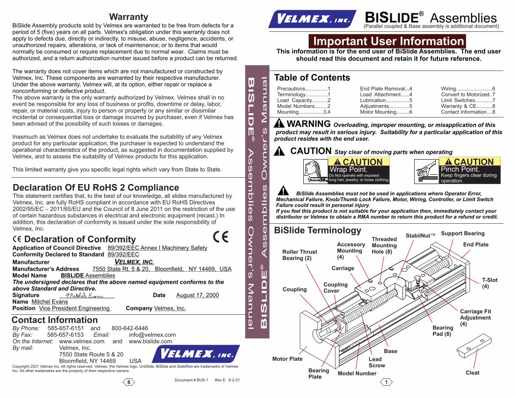
Motor Plate
Base
BearingPad (8)
LeadScrew
T-Slot(4)
End Plate
Support BearingStabilNut™
Carriage
AccessoryMounting(4)
Roller ThrustBearing (2)
Coupling
ThreadedMountingHole (8)
Carriage FitAdjustment(4)
CouplingCover
BiSlide Terminology
CleatBearingPlate
BSI
LIDE
Made in U
SA
Model #
MN10-0200-E
01-21
Order #
R
1234
Model Number
WarrantyBiSlide Assembly products sold by Velmex are warranted to be free from defects for aperiod of 5 (five) years on all parts. Velmex's obligation under this warranty does notapply to defects due, directly or indirectly, to misuse, abuse, negligence, accidents, orunauthorized repairs, alterations, or lack of maintenance; or to items that wouldnormally be consumed or require replacement due to normal wear. Claims must beauthorized, and a return authorization number issued before a product can be returned.
The warranty does not cover items which are not manufactured or constructed byVelmex, Inc. These components are warranted by their respective manufacturer.Under the above warranty, Velmex will, at its option, either repair or replace anonconforming or defective product.The above warranty is the only warranty authorized by Velmex. Velmex shall in noevent be responsible for any loss of business or profits, downtime or delay, labor,repair, or material costs, injury to person or property or any similar or dissimilarincidental or consequential loss or damage incurred by purchaser, even if Velmex hasbeen advised of the possibility of such losses or damages.
Inasmuch as Velmex does not undertake to evaluate the suitability of any Velmexproduct for any particular application, the purchaser is expected to understand theoperational characteristics of the product, as suggested in documentation supplied byVelmex, and to assess the suitability of Velmex products for this application.
This limited warranty give you specific legal rights which vary from State to State.
By Phone: 585-657-6151 and 800-642-6446By Fax: Email:585-657-6153 [email protected] the Internet: www.velmex.com and www.bislide.comBy mail: Velmex, Inc.
7550 State Route 5 & 20Bloomfield, NY 14469 USA
Copyright 2021 Velmex Inc. All rights reserved. Velmex, the Velmex logo, UniSlide, BiSlide and StabilNut are trademarks of VelmexInc. All other trademarks are the property of their respective owners.
Contact Information
Document # BUS-1 Rev E 6-2-21
BSI
LID
E®
Assem
blies O
wner’s
M
anualB
SI
LID
E®
Assem
blie
s O
wner’s
M
anual
!
!
!
CAUTION Stay clear of moving parts when operating
Declaration Of EU RoHS 2 ComplianceThis statement certifies that, to the best of our knowledge, all slides manufactured byVelmex, Inc. are fully RoHS compliant in accordance with EU RoHS Directives2002/95/EC – 2011/65/EU and the Council of 8 June 2011 on the restriction of the useof certain hazardous substances in electrical and electronic equipment (recast.) Inaddition, this declaration of conformity is issued under the sole responsibility ofVelmex, Inc.
Application of Council Directive 89/392/EEC Annex I Machinery SafetyConformity Declared to Standard 89/392/EEC
Manufacturer VELMEX, INC.Manufacturer’s Address 7550 State Rt. 5 & 20, Bloomfield, NY 14469, USAModel Name BISLIDE AssembliesThe undersigned declares that the above named equipment conforms to theabove Standard and Directive.Signature Date_________________ August 17, 2000Name Mitchel EvansPosition CompanyVice President Engineering Velmex, Inc.
Declaration of Conformity
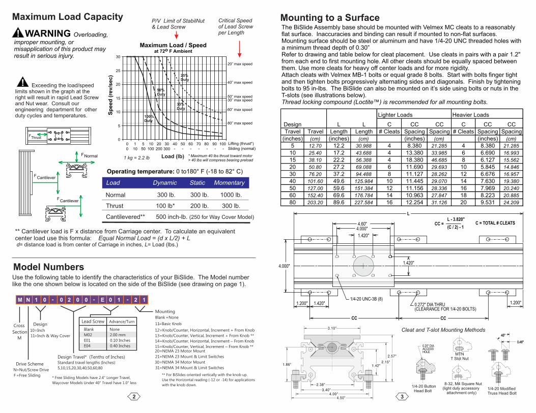
100%Duty
Maximum Load / Speedat 72o F Ambient
0
5
10
15
20
25
30
0
0
1
10
5
50
10
100
20
200
30
300
40 50 60 70 80 90 100
Sliding (normal)
Lifting (thrust*)
* Maximum 40 lbs thrust toward motor> 40 lbs will compress bearing preload
Sp
eed
(re
v/s
ec)
50” max speed
60” max speed
40” max speed
20” max speed
80” max speed
30” max speed
1 kg = 2.2 lb Load (lb)
50%Duty
- - - - - - -
25%Duty
33%Duty
Maximum Load Capacity
3
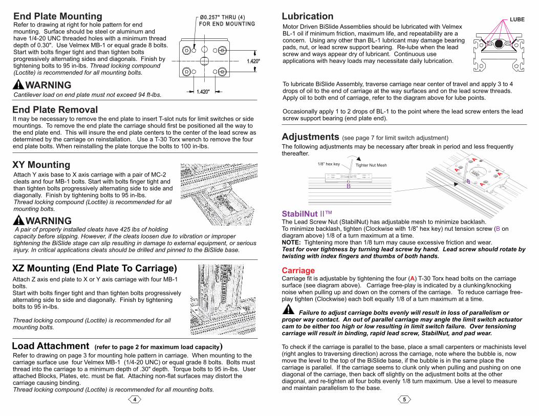
Mounting to a SurfaceThe BiSlide Assembly base should be mounted with Velmex MC cleats to a reasonablyflat surface. Inaccuracies and binding can result if mounted to non-flat surfaces.Mounting surface should be steel or aluminum and have 1/4-20 UNC threaded holes witha minimum thread depth of 0.30”Refer to drawing and table below for cleat placement. Use cleats in pairs with a pair 1.2"from each end to first mounting hole. All other cleats should be equally spaced betweenthem. Use more cleats for heavy off center loads and for more rigidity.Attach cleats with Velmex MB-1 bolts or equal grade 8 bolts. Start with bolts finger tightand then tighten bolts progressively alternating sides and diagonals. Finish by tighteningbolts to 95 in-lbs. The BiSlide can also be mounted on it’s side using bolts or nuts in theT-slots (see illustrations below).Thread locking compound (Loctite ) is recommended for all mounting bolts.™
Lighter Loads Heavier Loads
Design L L C CC CC C CC CC
Travel Travel Length Length # Cleats Spacing Spacing # Cleats Spacing Spacing
(inches) (cm) (inches) (cm) (inches) (cm) (inches) (cm)
5 12.70 12.2 30.988 4 8.380 21.285 4 8.380 21.285
10 25.40 17.2 43.688 4 13.380 33.985 6 6.690 16.993
15 38.10 22.2 56.388 4 18.380 46.685 8 6.127 15.562
20 50.80 27.2 69.088 6 11.690 29.693 10 5.845 14.846
30 76.20 37.2 94.488 8 11.127 28.262 12 6.676 16.957
40 101.60 49.6 125.984 10 11.445 29.070 14 7.630 19.380
50 127.00 59.6 151.384 12 11.156 28.336 16 7.969 20.240
60 152.40 69.6 176.784 14 10.963 27.847 18 8.223 20.885
80 203.20 89.6 227.584 16 12.254 31.126 20 9.531 24.209
CC =L - 3.820"
(C / 2) - 1C = TOTAL # CLEATS
1/4-20 UNC-3B (8)
0.272" DIA THRU(CLEARANCE FOR 1/4-20 BOLTS)
L
4.000"
4.000"4.60"
1.420"
CC CC
1.420"
1.200" 1.420" 1.200"
Cleat and T-slot Mounting Methods
0.46"
45°
0.20" DIAACCESSHOLE
1/4-20 ButtonHead Bolt
1/4-20 ModifiedTruss Head Bolt
MTNT Slot Nut
8-32, M4 Square Nut(light duty accessory
attachment only)
Critical Speedof Lead Screwper Length
P/V Limit of StabilNut& Lead Screw
2
Load Dynamic Static Momentary
Normal 300 lb. 300 lb. 1000 lb.
Thrust 100 lb* 200 lb. 300 lb.
Cantilevered** 500 inch-lb. (250 for Way Cover Model)
Cross
Section
M
Drive Scheme
N=Nut/Screw Drive
F=Free Sliding
Design
10=Inch
11=Inch & Way Cover
Design Travel* (Tenths of Inches)Standard travel lengths (Inches):
5,10,15,20,30,40,50,60,80
Mounting
Blank =None
11=Basic Knob
12=Knob/Counter, Horizontal, Increment + From Knob
13=Knob/Counter, Vertical, Increment + From Knob **
14=Knob/Counter, Horizontal, Increment From Knob–
15=Knob/Counter, Vertical, Increment From Knob **–20=NEMA 23 Motor Mount
21=NEMA 23 Mount & Limit Switches
30=NEMA 34 Motor Mount
31=NEMA 34 Mount & Limit Switches
Blank None
M02 2.00 mm
E01 0.10 Inches
E04 0.40 Inches
Lead Screw Advance/Turn
* Free Sliding Models have 2.4" Longer Travel,
Waycover Models Under 40" Travel have 1.0" less
** For BiSlides oriented vertically with the knob up.
Use the Horizontal reading (-12 or -14) for applications
with the knob down.
M N 1 0 - 0 2 0 0 - E 0 1 - 2 1
Model NumbersUse the following table to identify the characteristics of your BiSlide. The Model numberlike the one shown below is located on the side of the BiSlide (see drawing on page 1).
WARNING Overloading,!improper mounting, ormisapplication of this product mayresult in serious injury.
Exceeding the load/speedlimits shown in the graph at theright will result in rapid Lead Screwand Nut wear. Consult ourengineering department for otherduty cycles and temperatures.
Operating temperature: 0 to180° F (-18 to 82° C)
F Normal
FThrust
FCantilever
FCantilever
** Cantilever load is F x distance from Carriage center. To calculate an equivalentcenter load use this formula: Equal Normal Load = (d x L/2) + L
= distance load is from center of Carriage in inches, = Load (lbs.)d L
!
4
End Plate MountingRefer to drawing at right for hole pattern for endmounting. Surface should be steel or aluminum andhave 1/4-20 UNC threaded holes with a minimum threaddepth of 0.30". Use Velmex MB-1 or equal grade 8 bolts.Start with bolts finger tight and than tighten boltsprogressively alternating sides and diagonals. Finish bytightening bolts to 95 in-lbs. Thread locking compound(Loctite) is recommended for all mounting bolts.
Cantilever load on end plate must not exceed 94 ft-lbs.
XY MountingAttach Y axis base to X axis carriage with a pair of MC-2cleats and four MB-1 bolts. Start with bolts finger tight andthan tighten bolts progressively alternating side to side anddiagonally. Finish by tightening bolts to 95 in-lbs.Thread locking compound (Loctite) is recommended for allmounting bolts.
A pair of properly installed cleats have 425 lbs of holdingcapacity before slipping. However, if the cleats loosen due to vibration or impropertightening the BiSlide stage can slip resulting in damage to external equipment, or seriousinjury. In critical applications cleats should be drilled and pinned to the BiSlide base.
XZ Mounting (End Plate To Carriage)Attach Z axis end plate to X or Y axis carriage with four MB-1bolts.Start with bolts finger tight and than tighten bolts progressivelyalternating side to side and diagonally. Finish by tighteningbolts to 95 in-lbs.
Thread locking compound (Loctite) is recommended for allmounting bolts.
Load Attachment (refer to page 2 for maximum load capacity)Refer to drawing on page 3 for mounting hole pattern in carriage. When mounting to thecarriage surface use four Velmex MB-1 (1/4-20 UNC) or equal grade 8 bolts. Bolts mustthread into the carriage to a minimum depth of .30" depth. Torque bolts to 95 in-lbs. Userattached Blocks, Plates, etc. must be flat. Attaching non-flat surfaces may distort thecarriage causing binding.Thread locking compound (Loctite) is recommended for all mounting bolts.
WARNING!
WARNING!
1.420"
1.420"
End Plate RemovalIt may be necessary to remove the end plate to insert T-slot nuts for limit switches or sidemountings. To remove the end plate the carriage should first be positioned all the way tothe end plate end. This will insure the end plate centers to the center of the lead screw asdetermined by the carriage on reinstallation. Use a T-30 Torx wrench to remove the fourend plate bolts. When reinstalling the plate torque the bolts to 100 in-lbs.
A
A
A
A
B
LUBE
5
LubricationMotor Driven BiSlide Assemblies should be lubricated with VelmexBL-1 oil if minimum friction, maximum life, and repeatability are aconcern. Using any other than BL-1 lubricant may damage bearingpads, nut, or lead screw support bearing. Re-lube when the leadscrew and ways appear dry of lubricant. Continuous useapplications with heavy loads may necessitate daily lubrication.
To lubricate BiSlide Assembly, traverse carriage near center of travel and apply 3 to 4drops of oil to the end of carriage at the way surfaces and on the lead screw threads.Apply oil to both end of carriage, refer to the diagram above for lube points.
Occasionally apply 1 to 2 drops of BL-1 to the point where the lead screw enters the leadscrew support bearing (end plate end).
The following adjustments may be necessary after break in period and less frequentlythereafter.
StabilNut II™The Lead Screw Nut (StabilNut) has adjustable mesh to minimize backlash.To minimize backlash, tighten (Clockwise with 1/8” hex key) nut tension screw ( onBdiagram above) 1/8 of a turn maximum at a time.NOTE: Tightening more than 1/8 turn may cause excessive friction and wear.Test for over tightness by turning lead screw by hand. Lead screw should rotate bytwisting with index fingers and thumbs of both hands.
CarriageCarriage fit is adjustable by tightening the four ( ) T-30 Torx head bolts on the carriageAsurface (see diagram above). Carriage free-play is indicated by a clunking/knockingnoise when pulling up and down on the corners of the carriage. To reduce carriage free-play tighten (Clockwise) each bolt equally 1/8 of a turn maximum at a time.
Failure to adjust carriage bolts evenly will result in loss of parallelism orproper way contact. An out of parallel carriage may angle the limit switch actuatorcam to be either too high or low resulting in limit switch failure. Over tensioningcarriage will result in binding, rapid lead screw, StabilNut, and pad wear.
To check if the carriage is parallel to the base, place a small carpenters or machinists level(right angles to traversing direction) across the carriage, note where the bubble is, nowmove the level to the top of the BiSlide base, if the bubble is in the same place thecarriage is parallel. If the carriage seems to clunk only when pulling and pushing on onediagonal of the carriage, then back off slightly on the adjustment bolts at the otherdiagonal, and re-tighten all four bolts evenly 1/8 turn maximum. Use a level to measureand maintain parallelism to the base.
Adjustments (see page 7 for limit switch adjustment)
!
Tighter Nut Mesh1/8” hex key
B
6
Motor Mounting
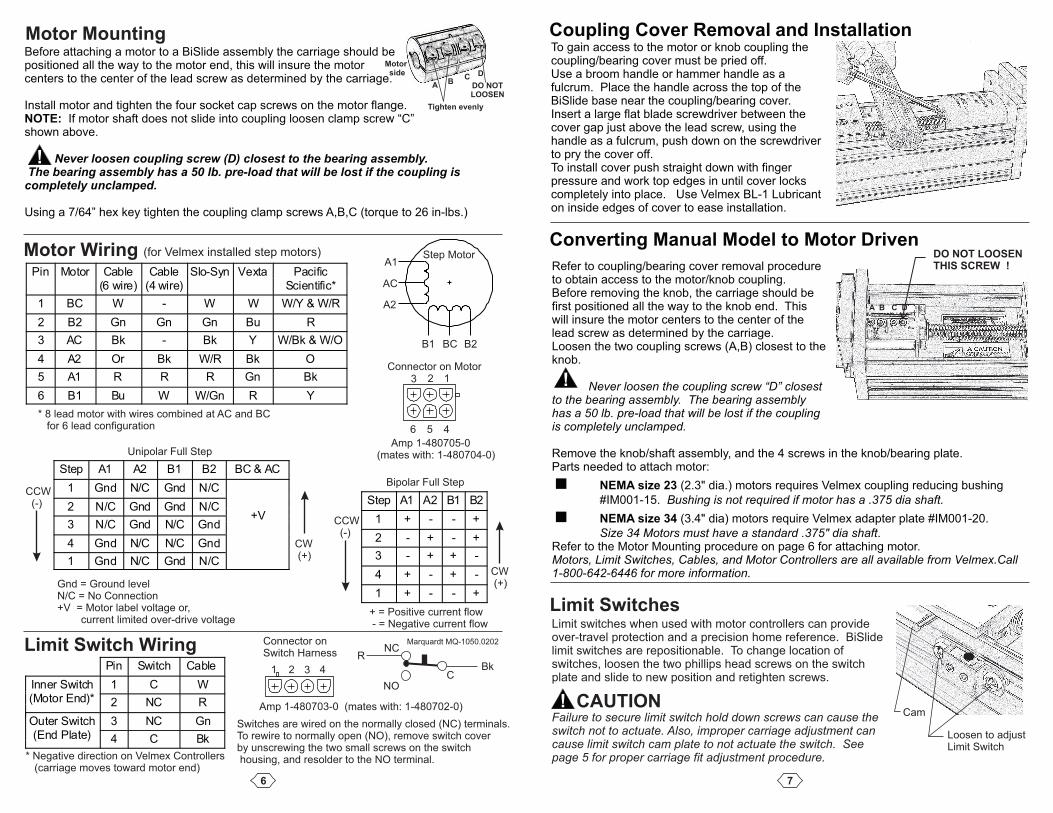
Motor Wiring (for Velmex installed step motors)
Limit Switch Wiring
Before attaching a motor to a BiSlide assembly the carriage should bepositioned all the way to the motor end, this will insure the motorcenters to the center of the lead screw as determined by the carriage.
Install motor and tighten the four socket cap screws on the motor flange.NOTE: If motor shaft does not slide into coupling loosen clamp screw “C”shown above.
Never loosen coupling screw (D) closest to the bearing assembly.The bearing assembly has a 50 lb. pre-load that will be lost if the coupling iscompletely unclamped.
Using a 7/64” hex key tighten the coupling clamp screws A,B,C (torque to 26 in-lbs.)
1 2 3 4
Amp 1-480703-0 (mates with: 1-480702-0)
* Negative direction on Velmex Controllers(carriage moves toward motor end)
Connector onSwitch Harness
Switches are wired on the normally closed (NC) terminals.To rewire to normally open (NO), remove switch coverby unscrewing the two small screws on the switchhousing, and resolder to the NO terminal.
C
NC
NO
RBk
Marquardt MQ-1050.0202
123
456
Amp 1-480705-0(mates with: 1-480704-0)
* 8 lead motor with wires combined at AC and BCfor 6 lead configuration
Connector on Motor
A1
AC
A2
B1 BC B2
Step Motor
Unipolar Full Step
Bipolar Full StepCCW(-)
CW(+)
CCW(-)
CW(+)Gnd = Ground level
N/C = No Connection+V = Motor label voltage or,
current limited over-drive voltage+ = Positive current flow- = Negative current flow
!
Tighten evenly
Motorside
A BC D
DO NOTLOOSEN
Pin Switch Cable
Inner Switch(Motor End)*
1 C W
2 NC R
Outer Switch(End Plate)
3 NC Gn
4 C Bk
Pin Motor Cable(6 wire)
Cable(4 wire)
Slo-Syn Vexta PacificScientific*
1 BC W - W W W/Y & W/R
2 B2 Gn Gn Gn Bu R
3 AC Bk - Bk Y W/Bk & W/O
4 A2 Or Bk W/R Bk O
5 A1 R R R Gn Bk
6 B1 Bu W W/Gn R Y
Step A1 A2 B1 B2 BC & AC
1 Gnd N/C Gnd N/C
+V2 N/C Gnd Gnd N/C
3 N/C Gnd N/C Gnd
4 Gnd N/C N/C Gnd
1 Gnd N/C Gnd N/C
Step A1 A2 B1 B2
1 + - - +
2 - + - +
3 - + + -
4 + - + -
1 + - - +
7
Coupling Cover Removal and Installation
Converting Manual Model to Motor Driven
To gain access to the motor or knob coupling thecoupling/bearing cover must be pried off.Use a broom handle or hammer handle as afulcrum. Place the handle across the top of theBiSlide base near the coupling/bearing cover.Insert a large flat blade screwdriver between thecover gap just above the lead screw, using thehandle as a fulcrum, push down on the screwdriverto pry the cover off.To install cover push straight down with fingerpressure and work top edges in until cover lockscompletely into place. Use Velmex BL-1 Lubricanton inside edges of cover to ease installation.
Refer to coupling/bearing cover removal procedureto obtain access to the motor/knob coupling.Before removing the knob, the carriage should befirst positioned all the way to the knob end. Thiswill insure the motor centers to the center of thelead screw as determined by the carriage.Loosen the two coupling screws (A,B) closest to theknob.
Never loosen the coupling screw “D” closestto the bearing assembly. The bearing assemblyhas a 50 lb. pre-load that will be lost if the couplingis completely unclamped.
Remove the knob/shaft assembly, and the 4 screws in the knob/bearing plate.Parts needed to attach motor:
< (2.3" dia.) motors requires Velmex coupling reducing bushingNEMA size 23
#IM001-15. Bushing is not required if motor has a .375 dia shaft.
< (3.4" dia) motors require Velmex adapter plate #IM001-20.NEMA size 34
Size 34 Motors must have a standard .375" dia shaft.Refer to the Motor Mounting procedure on page 6 for attaching motor.Motors, Limit Switches, Cables, and Motor Controllers are all available from Velmex.Call1-800-642-6446 for more information.
Limit SwitchesLimit switches when used with motor controllers can provideover-travel protection and a precision home reference. BiSlidelimit switches are repositionable. To change location ofswitches, loosen the two phillips head screws on the switchplate and slide to new position and retighten screws.
Failure to secure limit switch hold down screws can cause theswitch not to actuate. Also, improper carriage adjustment cancause limit switch cam plate to not actuate the switch. Seepage 5 for proper carriage fit adjustment procedure.
CAUTION!
Loosen to adjustLimit Switch
Cam
!
DO NOT LOOSENTHIS SCREW !
A B C D