b services-final-report
TRANSCRIPT

SCHOOL OF ARCHITECTURE, BUILDING & DESIGN
BUILDING SERVICES (BLD 61403)
Project 2 - Case Study and
Documentation of Building Services
Systems
PJ TRADE CENTER
Leong Vui Yung 0320362
Fung Ho Yeng 0319473
Ivy Voo Vui Yee 0319534
Lim Jern Jack 0317139
Liong Shun Qi 0315942
Tan Hsuan Lin 0318975
Ar. Sateerah Hassan

TABLE OF CONTENTS
1.0 INTRODUCTION 1 - 2
1.1 ABSTRACT 3
1.2 ACKNOWLEDGEMENT 4
2.0 FIRE PROTECTION SYSTEM 5
2.1 Introduction 6
2.2 Literature Review 7 - 8
2.2.1 Fire Safety
2.2.2 Class of Fire
2.3 Active Fire Protection 9 - 31
2.3.1 Introduction
2.3.2 Fire Detection
2.3.2.1 Manually Activated Devices
2.3.2.2 Automatically Activated Devices
2.3.3 Alarm System
2.3.4 Fireman Switch
2.3.5 Fire Control System
2.3.5.1 Sprinkler System
2.3.6 Fire Supporting System
2.3.7 Fire Extinguisher
2.3.7.1 Purpose for using Dry Powder
Extinguisher
2.3.7.2 Purpose for using CO2 Extinguisher
2.3.8 Hose Reel System
2.3.9 Wet Riser System
2.3.10 Fire Hydrant
2.3.11 Analysis
2.4 Passive Fire Protection 32 - 53
2.4.1 Introduction

2.4.2 Compartmentation
2.4.2.1 Smoke Barriers and Fire Curtain
2.4.3 Fire Resistant Escape Staircase
2.4.3.1 Type of Staircase
2.4.3.2 Type of Material Used
2.4.3.3 Location
2.4.4 Horizontal Escape
2.4.5 Fire Resistant Doors
2.4.6 Fibre Reinforced Plastic Door
2.4.7 Fire Lift
2.4.8 Lightning and Signage
2.4.8.1 Emergency Sign and Exit
2.4.8.2 Emergency Exit Light
2.4.8.3 Fire Indicator Light
2.4.8.4 Safety and Instruction Signage
2.4.9 Analysis
3.0 MECHANICAL VENTILATION AND AIR CONDITIONING SYSTEM 54
3.1 Introduction 55
3.2 Literature Review 56
3.2.1 Mechanical Ventilation
3.2.2 Air Conditioning system
3.3 Mechanical Ventilation 57 - 66
3.3.1 Introduction
3.3.2 Components of System Involved in Mechanical
Ventilation System
3.3.2.1 Ducting System
3.3.2.2 Extract Ventilation
3.3.2.3 Pressurisation and Exhaust System for
Fire Protection
3.4 Air-Conditioning System 67 - 79
3.4.1 Introduction
3.4.2 Types of Air Conditioning System

3.4.2.1 Room Air Conditioner
3.4.2.2 Package Unit Air Conditioning System
3.4.2.3 Centralized / Plant Air Conditioning System
3.4.2.4 Split Unit Air Conditioning System
3.4.3 Components of the Split Unit Air Conditioning System
3.4.3.1 Outdoor Unit
3.4.3.2 Indoor Unit
3.4.4 Operation of System
3.4.5 UBBL requirements of Related Regulations
3.4.6 Analysis
4.0 MECHANICAL TRANSPORTATION SYSTEM 80
4.1 Introduction 81
4.2 Literature Review 82 - 85
4.2.1 Electric Lift
4.2.1.1 Traction Lift
4.2.1.2 Machine Room-less Lift
4.2.2 Hydraulic Lift
4.2.3 Performance of Lift
4.3 Placement of Lift 86 - 94
4.3.1 Lift Lobby
4.3.2 Fire Safety
4.3.2.1 Protected Lobby
4.3.2.2 Sprinklers & Smoke Detectors
4.3.2.3 Fireman Lift’s Switch and Emergency
Exit Indicator
4.3.3 Call Button & Hall Lantern
4.4 Operation of Lift 95 - 104
4.4.1 Gearless Traction Lift
4.4.2 Counterweight
4.4.3 Cables
4.4.4 Lift Car
4.4.4.1 Lift Door

4.4.4.2 Lift Car Control
4.4.4.3 Lighting & Ventilation
4.4.4.4 Emergency Railing
4.5 Safety Devices 105
4.6 Machine Room 106 - 109
4.6.1 Ventilation
4.6.2 Fire Safety
4.6.3 Control Panel
4.7 Control Room 110 - 111
4.7.1 Lift Supervisory Level
4.7.2 Central Monitor System
4.8 Analysis 112
5.0 CONCLUSION 113 - 114
6.0 REFERENCES 115 - 118
7.0 APPENDIX 119


1 | P a g e
1.0
INTRODUCTION

2 | P a g e
1.0 INTRODUCTION
PJ Trade Centre is an office project developed by Tujuan Gemilang Sdn Bhd. It is a
bold design based on a Malaysian paradigm and is rooted in the local culture climate
and context. PJ Trade Centre is located in Damansara Perdana, Petaling Jaya, on a
5.4 acre site and consists of 4 office towers, with over 1 million square feet of office
space. The project was completed in December 2009 and is now fully occupied.
Compared to other office building design, the architect Kevin Mark Low intelligently
designed this PJ Trade Centre where the building has a low-tech appearance yet
modern look. Moreover, the building is designed as comfortable and healthy
workplaces, with plenty of natural light and cross ventilation. Energy-efficient and
eco-friendly design feature leads to low maintenance cost, but more importantly, it
has the potential to enhance productivity – lower absenteeism, improved staff morale,
higher quality of work.
There is a feeling of being close to nature, with a lushly landscaped Plaza of
2.5acres and 12 Sky Terraces with hanging vines and wall creepers. Many office
units have balconies of about 325 square feet and open-to-sky washrooms.
PJ Trade Centre reflects a ‘boutique’ property – there are only 1 to 4 units per floor
with a minimum size of 2,100 square feet. Each unit has its own pantry and
washroom, and it is higher than normal ceilings of 3.8 metres.

3 | P a g e
1.1 ABSTRACT
For this project, we were to select a building of 5-storey-high and perform a thorough
analysis on how the service systems in the building function in a qualitative form.
This could be achieved by experimental learning through own observations and
experience.
This case study report will be focusing on the services systems in PJ Trade Centre,
such as mechanical ventilation system, air-conditioning system, mechanical
transportation system and fire protection system. This report aims to introduce the
systems and analyse the function based on our own understanding. Uniform Building
By Law (UBBL) and Malaysian Standard (MS1525) are being referred to get more
information on the regulations of the services.

4 | P a g e
1.2 ACKNOWLEDGEMENT
We would like to thank PJ Trade Centre for allowing our team to have a visit on the
building services. We are also grateful that the technicians that spent their weekend
on giving us all the necessary information throughout the building including all
mechanical, electrical, fire protection and architectural drawings. Without their help,
we will not be able to finish the project.
We would also like to thank the technician for bringing us a tour on the building
through the prominent service rooms. We are grateful that they relentlessly
explaining the systems of each room and the machines within.
We would like to extend our gratitude to each individual who has helped and
assisted us to complete this research report as without your involvement, this report
would be insufficient and unsatisfactory. At last, a special thanks to our tutor, Ar.
Sateerah for guiding us through each tutorial and providing us with an aim to
accomplish the task.
5 | P a g e
2.0
FIRE PROTECTION
SYSTEM

6 | P a g e
2.1 INTRODUCTION
Fire protection system is used to practice the mitigation of the unwanted effects of
potentially destructive fire that will happen in the building. As a qualified designer or
architect, it is necessary and important to understand or well design in fire protection
system. Choosing the right fire protection solutions and having a good design in fire
protection system are critical to ensuring the protection of the facility and the users.
A good fire protection design and system is to have a good control on the fire and
extinguish it on time.
A building is required to apply fire protection systems into the design and the building
itself in Malaysia. The fire protection system has two individual sub-components, the
Active Fire Protection System (AEPS) and the Passive Fire Protection System
(PEPS).
Designers or architects should be able to apply the suitable and different types of fire
protection systems in the building. The report will show the types of fire protection
systems that have been used in PJ Trade Center efficiently.

7 | P a g e
2.2 LITERATURE REVIEW
2.2.1 Fire Safety
According to Oxford Dictionary, fire is a process which substances combine with
oxygen and produces combustion or burning. A fire can spread at a rate of 4.6
meters per second (Binggeli, 2014). Also, fire is supported by three essential factors,
which are fuel, heat and oxygen.
FIGURE 2.2.1A: Fire Triangle
SOURCE: http://work.alberta.ca/searchaarc/884.html
Fire Triangle is a simple model for understanding the necessary ingredients for most
fires. Figure 2.1 illustrates the three elements for fire to ignite: heat, fuel and an
oxidizing agent.
8 | P a g e
2.2.2 Class of Fire
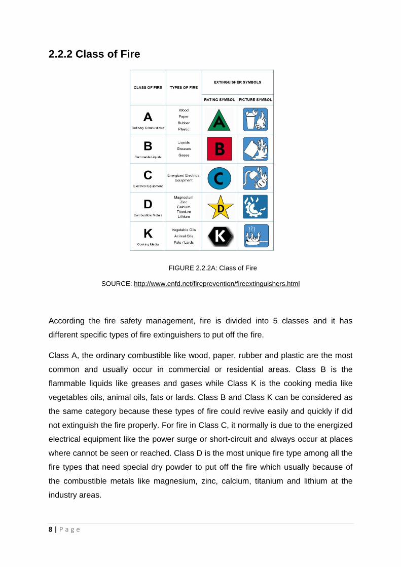
FIGURE 2.2.2A: Class of Fire
SOURCE: http://www.enfd.net/fireprevention/fireextinguishers.html
According the fire safety management, fire is divided into 5 classes and it has
different specific types of fire extinguishers to put off the fire.
Class A, the ordinary combustible like wood, paper, rubber and plastic are the most
common and usually occur in commercial or residential areas. Class B is the
flammable liquids like greases and gases while Class K is the cooking media like
vegetables oils, animal oils, fats or lards. Class B and Class K can be considered as
the same category because these types of fire could revive easily and quickly if did
not extinguish the fire properly. For fire in Class C, it normally is due to the energized
electrical equipment like the power surge or short-circuit and always occur at places
where cannot be seen or reached. Class D is the most unique fire type among all the
fire types that need special dry powder to put off the fire which usually because of
the combustible metals like magnesium, zinc, calcium, titanium and lithium at the
industry areas.

9 | P a g e
2.3 ACTIVE FIRE PROTECTION SYSTEM
2.3.1 Introduction
Active fire protection system is a bunch of systems or equipment that require action
or motion to activate the system and equipment on the fire outbreak. An action can
be manually operated such as fire extinguishers and fire alarm units which requires
to break glass. However, sprinkle and smoke detector will be activated automatically.
In the case of PJ Trade Centre, the system and equipment they used are the fire
alarm unit, smoke detector, emergency voice communication system, emergency
communication system, emergency light, fireman switch, sprinkle, CO2 suppression
system, fire extinguisher, wet riser system, hose reel system and fire hydrant. The
duty of all these systems and equipment is to extinguish the fire, control the fire or
provide exposure protection to prevent domino effects.
.
2.3.2 Fire Detection
Fire detection is used to detect an circumstance, then transfer and alert to the control
panel so that it can give a notification to occupants to take notes and actions.
Different types of detection designs will be used in different buildings and different
places. So, the detection comes out with automatic activation and manual activation
for convenience and friendly usage of the occupants. Automatic detection will be
activated when it senses smoke or heat whilst manual detection will be activated by
the occupants by breaking the glass unit, pulling or pressing the fire alarm pull
station. The fire control system will immediately work once the detection senses the
occurrences. It is very important and necessary to place the detection at the eye
level that can be seen and reached easily.
These two types of fire detections are used at PJ Trade Centre.

10 | P a g e
2.3.2.1 Manually Activated Devices
Manually activated devices are under the manual detection that requires occupant’s
intervention to activate it. For the manual detection it is usually placed on the wall
1.4m from the ground which is easily reached by the occupants. The following will
show the types of manually activated devices that are being used in PJ Trade Centre.
FIGURE 2.3.2.1A: Break glass fire alarm unit placed on the wall at reachable height.
Clause 237, Uniform Building By Law 1984 states that:
Fire alarms,
(1) Fire alarms shall be provided in accordance with the Tenth Schedule to these By-
laws.

11 | P a g e
(2) All premises and building with gross floor area excluding car park and storage
area exceeding 9290 square metres or exceeding 30.5 metres in height shall be
provided with a two-stage alarm system with evacuation (continuous signal) to be
given immediately in the affected section of the premises while an alert (intermittent
signal) be given in adjoining section.
(3) Provision shall be made for the general evacuation of the premises by action of a
master control.
2.3.2.2 Automatically Activated Devices
The automatic activated devices will be activated depending on the building
surrounding and will notice the occupants immediately and directly. One of the most
common automatic activated device is the smoke detector which will be triggered by
the heat of the smoke in the building. In this case, the entire building of PJ Trade
Centre is using only smoke detectors as the automatic activated device.
When smoke detectors sense the smoke, it will immediately send a signal to a fire
alarm control panel which is considered as a part of the fire system. For the smoke
alarm, it has two ways to work which are optical detection methods and physical
process (Ionization). The light sensor used in the optical detector is to detect the
smoke. Furthermore, ionization detector is more responsive to open flame fires.
Figure 2.3.2.2A and figure 2.3.2.2B are showing the diagram of how the two
detectors work.

12 | P a g e
FIGURE 2.3.2.2A: Radioactive source is used to ionize the air within the sensing chambers.
SOURCE: http://www.slideshare.net/RafayAhmad/fire-fighting-ppt-final
FIGURE 2.3.2.2B: Reflected or scattered light is used to indicate the presence of visual smoke.
SOURCE: http://www.slideshare.net/RafayAhmad/fire-fighting-ppt-final

13 | P a g e
FIGURE 2.3.2.2C: Important of having a fire detection in our living area so that we could escape and
put out the fire in a certain timing before it is too late.
SOURCE: http://www.hlssecurity.ca/Support1.html
FIGURE 2.3.2.2D: Smoke detector used in PJ Trade Center.

14 | P a g e
2.3.3 Alarm System
Having a good alarm system, it is better to include visual and audio to alert the
occupants when fire is happening. Emergency lights, alarm bells, guide lights and
the emergency voice message communication such as the direct phone calling to
the control room fire station can be combined with the alarm system, so that the fire
protection system could guide occupants to escape and reach help immediately.
This kind of combination system is usually found in a bigger scale or high-rise
building such as PJ Trade Centre.
FIGURE 2.3.3A & FIGURE 2.3.3B : Emergency voice communication system that used in PJ Trade
Centre looks like a normal speaker and hang on the wall. It will be activated when the alarm system is
on.
For the PJ Trade Centre, the emergency voice communication system (EVCS) will
play out the pre-recorded message when the emergency happens.
Clause 239, Uniform Building By Law 1984 states that:
Voice communication system,
There shall be two separate approved continuously electrically supervised voice

15 | P a g e
communication systems, one a fire brigade communication system and the other a
public address system between the central control station and the following areas:
(a) Lifts, lift lobbies, corridors and staircases;
(b) In every office area exceeding 92.9 square metres in area
FIGURE 2.3.3C & FIGURE 2.3.3D: Emergency light, alarm bell and emergency exit signage are also
provided at PJ Trade Center in the escape staircase.
FIGURE 2.3.3E: Emergency communication system is provided for the occupants to contact the
control center or directly reach to the fire station.

16 | P a g e
.
FIGURE 2.3.3 F: Fire Alarm Control Panel is to receive information from the sensors designed which
can detect the fire. It provides an automatic control equipment and transmission of information for
firefighting based on a predetermined sequence.
.
2.3.4 Fireman Switch
When a fireman switch is triggered, it will switch off the power supply of the specific
power system automatically and immediately. It is located at every level of the
building and has different switches that show different types of electrical supply to be
switched off. The fireman switch can only operated by fireman.
FIGURE 2.3.4A: Fireman switch is placed at a certain height on the wall so that people will not touch
it or press it randomly.

17 | P a g e
2.3.5 Fire Control System
2.3.5.1 Sprinkler System
Fire sprinkle is the most common and major defense system. It works with a
combination of water tanks, piping and pumps systems. A signal will be transferred
immediately to the sprinkler control box when the heat detector detects the heat. The
water pump will then start to pump water from tank with high pressure to the
sprinkler head.
FIGURE 2.3.5.1A: Fire sprinkler system of residential and commercial buildings.
SOURCE: http://www.calcountiesfire.com/fire-sprinkler-service/

18 | P a g e
FIGURE 2.3.5.1B: The fire sprinkle diagrams is showing the installation of the combination of fire
pumps, fire pumps, water tank, control valve sets, sprinkle heads, flows switches, pressure switches,
pipe work and valves. The system will work automatically without human intervention.
SOURCE: http://www.firefightingindia.com/fire-sprinkler-system-1.html
FIGURE 2.3.5.1C: One of the sprinkle layout drawing in PJ Trade Centre Basement 2.
19 | P a g e
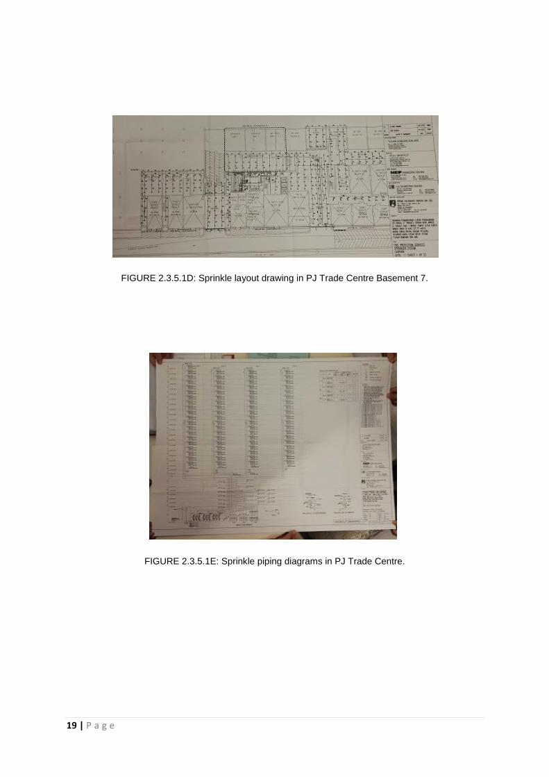
FIGURE 2.3.5.1D: Sprinkle layout drawing in PJ Trade Centre Basement 7.
FIGURE 2.3.5.1E: Sprinkle piping diagrams in PJ Trade Centre.

20 | P a g e
FIGURE 2.3.5.1F: Sprinkle system installed in PJ Trade Centre.
FIGURE 2.3.5.1G: Sprinkler valves, wet riser valves and pressure switches.

21 | P a g e
Clause 226, Uniform Building By Law 1984 states that:
Automatic system for hazardous occupancy,
Where hazardous processes, storage or occupancy are of such character as to
require automatic sprinklers or other automatic extinguishing system, it shall be of a
type of and standard appropriate to extinguish fires in the hazardous materials stored
or handled or for the safety of the occupants.
Clause 228, Uniform Building By Law 1984 states that:
Sprinkler valves,
(1) Sprinkler valves shall be located in a safe and enclosed position on the exterior
wall and shall be readily accessible to the Fire Authority.
(2) All sprinkler systems shall be electricity connected to the nearest fire station to
provide immediate and automatic relay of the alarm when activated.
2.3.6 Fire Supporting System
A CO2 suppression system is an efficient as a fire suppression agent which contains
colorless, odorless, electrically non-conductive gas. It uses an intelligent, reliable and
fast-acting control panel to sense the fire quickly before it brings damages to the
property and occupants.
The CO2 suppression system can be found in the electrical room. When there is fire,
CO2 will be released which will reduce the oxygen in the air. It can be activated
manually by breaking the glass lever.

22 | P a g e
FIGURE 2.3.6A: CO2 storage is placed inside the same room with the electrical control boxes.
FIGURE 2.3.6B: CO2 storage is placed at the corner so that it will not block the way and for safety
purpose.

23 | P a g e
2.3.7 Fire Extinguisher
Fire extinguishers are required to have in a commercial and residential buildings for
safety purpose. Occupants can use the fire extinguisher to extinguish fire or to
control the fire level before it turns to higher level. Fire extinguishers are mostly
placed at the area which is easy to access, visible and reachable so that the
occupants can get it during the emergency.
For PJ Trade Center, there are two different types of fire extinguishers which are dry
powder system and CO2 system. These two types of fire extinguishers have their
own properties and usage which depends on the types or class of the fire and the
situation. The weight of dry powder fire extinguisher is around 9KG and for the CO2
is around 3KG.
2.3.7.1 Purpose for using Dry Powder Extinguisher
ABC powder is the other name of dry powder system. It is used when / for:
Type A fire is caused by wood, paper and textiles.
Type B fire is caused by flammable liquids.
Type C fire is caused by flammable gases.
ABC powder is electrical contact..
2.3.7.2 Purpose for using CO2 Extinguisher
CO2 is used when / for:
Type B fire is caused by flammable liquids
CO2 system is electrical contact.
24 | P a g e
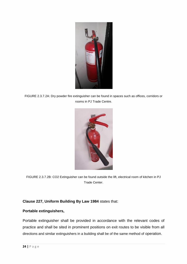
FIGURE 2.3.7.2A: Dry powder fire extinguisher can be found in spaces such as offices, corridors or
rooms in PJ Trade Centre.
FIGURE 2.3.7.2B: CO2 Extinguisher can be found outside the lift, electrical room of kitchen in PJ
Trade Center.
Clause 227, Uniform Building By Law 1984 states that:
Portable extinguishers,
Portable extinguisher shall be provided in accordance with the relevant codes of
practice and shall be sited in prominent positions on exit routes to be visible from all
directions and similar extinguishers in a building shall be of the same method of operation.

25 | P a g e
2.3.8 Hose Reel System
Fire hose reel is a high pressure hose that carries water or fire retardant like foam to
put off the fire. It is attached to a fire engine or fire hydrant when it is placed outdoor.
In another way, it is attached to the building’s standpipe or plumbing system
permanently when it is placed indoor. It can be found or seen at every level of lift
area or high-risk areas for example electrical room or near to the staircase.
FIGURE 2.3.8A, FIGURE 2.3.8B & FIGURE 2.3.8C: There are many different type of design of fire
hose reel room in PJ Trade Center.
FIGURE 2.3.8D: Fire hose reel details drawing.

26 | P a g e
Clause 230, Uniform Building By Law 1984 states that:
Installation and testing of dry rising system,
(1) Dry rising system shall be provided in every building in which the topmost floor is
more than 18.3 metres but less than 30.5 metres above fire appliance access level.
(2) A hose connection shall be provided in each fire fighting access lobby.
(3) Dry risers shall be of minimum “Class C” pipes with fittings and connections of
sufficient strength to withstand 21 bars water pressure.
2.3.9 Wet Riser System
Wet riser system is a system of pipework and valves that keeps water for firefighting
purpose. That means firefighters have no need to create another distribution system
during a fire outbreak in the building. The wet riser system is required when the
building is more than 30.5 meters above fire appliance access level. (Uniform
Building By-Laws 1985, clause 231)
FIGURE 2.3.9A: The step of using the wet riser system is to connect and plug the provided hose with
the wet riser plumbing

27 | P a g e
FIGURE 2.3.9B: The piping distribution system from the wet riser.
SOURCE: http://sprinksistemleri.net/index.php?142=blog&id=33&dil=tr
FIGURE 2.3.9C & FIGURE 2.3.9D: The fire pump room located at the basement. A lot of piping work
such as for sprinkler, wet riser and hose reel can be found in the room.

28 | P a g e
FIGURE 2.3.9E: All the plumbing is indicting the name of the pipe. It will be more convenient and
efficient during the maintenance and repair works.
FIGURE 2.3.9F: The water pumps room. In the case of PJ Trade Center, it has 3 water tanks ready
for wet riser, sprinkle and hose reel.

29 | P a g e
FIGURE 2.3.9G: Pressure meter for hose reel, wet riser and sprinkle.
Clause 231, Uniform Building By Law 1984 states that:
Installation and testing of wet rising system,
(1) Wet rising systems shall be provided in every building in which the topmost floor
is more than 30.5 metres above fire appliance access level.
(2) A hose connection shall be provided in each fire fighting access lobby.
(3)A wet riser shall be provided in every staircase which extends from the ground
floor level to the roof and shall be equipped with a three-way 63.5 millimetres outlet
above the roof line.
Clause 248, Uniform Building By Law 1984 states that:
Marking on the wet riser, etc,
(1) Wet riser, dry riser, sprinkler and other fire installation pipes and fittings shall be
painted red.
(2) All cabinets and ares recessed in walls for location of fire installations and
extinguishers shall be clearly identified to the satisfaction of the Fire Authority or
otherwise clearly identified.

30 | P a g e
2.3.10 Fire Hydrant
The purpose of having a fire hydrant is to provide source of water to the urban,
suburban as well as rural areas for firefighters to tap into the water supply to
extinguish the fire. The hose has to be attached on with the opening of fire hydrant
and open up the valve on the hydrant so it can provide a strong water flow. Fire
engine will be used to increase the water pressure when it is necessarily. Fire
hydrants can be found at outdoor and along the road that can let the firefighters
reach and use easily.
FIGURE 2.3.10A: A typical fire hydrant can be seen beside the road in PJ Trade Center.
Clause 225, Uniform Building By Law 1984 states that:
Detecting and extinguishing fire,
(1) Every building shall be provided with means of detecting and extinguishing fire
and with fire alarms together with illuminated exit signs in accordance with the
requirements as specified in the Tenth Schedule to these By-laws.
(2) Every building shall be served by at least one fire hydrant located not more than
91.5 metres from the nearest point of fire brigade access.
(3) Depending on the size and location of the building and the provision of access for
fire appliances, additional fire hydrant shall be provided as may be required by the
Fire Authority.

31 | P a g e
2.3.11 Analysis
Based on our observation, active fire protection system has applied effectively and
safely in PJ Trade Centre as it adheres to the UBBL 1984. Sprinkles are applied in
corner of the building even in car park. Fire extinguisher can be found outside the lift
or at the corner of the rooms. The technicians have to take the responsibility to make
sure the expiry date or the maintenance date of the fire extinguisher so that it could
work well during the fire outbreak. The fire escape staircase in PJ Trade Centre has
a lot of active fire protection system installed to prepare for the emergency and to
guard and help the occupants during the outbreak. A massive water pump room is
placed underground and checked according the schedule to provide enough water
supply to the equipment effectively. A yellow cross box beside the fire hydrant can
be seen because there is no vehicle allowed to stop or park in front the fire hydrant
except the fire truck. Last but not least, PJ Trade Centre is good in installing suitable
active fire protection systems and equipment based on the functions and usages of
the spaces and needs.

32 | P a g e
2.4 PASSIVE FIRE PROTECTION
2.4.1 Introduction
The installation of passive fire protection system are use to contain fires or slow
down the spread of fire efficiently for users escaping but not stop it entirely in the
event of fire. Mechanical and electrical activation are not included in this system.
Passive fire protection are involved as part of the fabric of the buildings in the form of
fire resistant walls, both floors and doors without the needs of maintenance once
they are installed. This system must be considered at the planning design stage in
the building design with various of particular design and solutions in order to suit the
building requirements respectively.
According to Nulifire (2014), the aim of passive fire protection system is to contain
the fire by:
The use of fire rated partitions and doors to prevent the moving of fire and smoke
from one compartment to another;
Delaying the collapse of the building structure; and
Delaying the growth on the fire;

33 | P a g e
2.4.2 Compartmentation
The purpose group and compartment play an important role in the passive fire
protection system through the separation of the building into few compartments to
prevent the fire spreading briskly. It prevents the rate of fire spreads that overtake
the occupants’ rate of escape. Purpose group and compartment also work alongside
the active fire protection to enhance occupants’ chances to escape in the event of
fire.
The compartment of lift lobby and escape staircase in the chosen block (Block B -
Bata Tower) of PJ Trade Centre are as the following.
FIGURE 2.4.2A: Block B in Layout plan of PJ Trade Centre

34 | P a g e
Ground floor
FIGURE 2.4.2B: Ground floor plan of Block B
It shows the location of fire resistant escape staircase in lift lobby compartment and
fire escape staircase compartment at Ground floor of Block B.
FIGURE 2.4.2C: Fire resistant escape staircase compartment in lift lobby of Ground Floor

35 | P a g e
19Th floor plan -Lift motor room
FIGURE 2.4.2D: 19TH
floor plan of Block B
The 19Th floor at level 21 is the top floor of the Block B and where the lift motor room,
cold water tank, cold water pump room located only access by fire resistant escape
staircase.

36 | P a g e
Basement 1 Car park (Level -1)
FIGURE 2.4.2E: Basement 1 car park floor plan of Block B
It shows the location of fire resistant escape staircase in lift lobby compartment and
fire escape staircase compartment at Basement 1 car park of Block B.
FIGURE 2.4.2F: Fire resistant escape staircase compartment in lift lobby of Basement 1 car park.

37 | P a g e
Basement 2 Car park
FIGURE 2.4.2G: Basement 2 car park floor plan of Block B
It shows the location of fire resistant escape staircase in lift lobby compartment and
fire escape staircase compartment at Basement 2 car park of Block B.
FIGURE 2.4.2H: Fire resistant escape staircase compartment in lift lobby of Basement 2 car park.

38 | P a g e
Basement 7
FIGURE 2.4.2I: Lower ground 7 Detail pump room layout of Block B.
It shows the location of fire resistant escape staircase in lift lobby compartment at
Basement 7 of Block B.
Clause 137, Uniform Building By Law 1984 states that:
Floor in building exceeding 30 metres in height to be constructed as
compartment floor,
In any building which exceeds 30 metres in height, any floor which is more than 9
metres above ground floor level which separates one storey from another storey,
other than a floor which is either within a maisonette or a mezzanine floor shall be
constructed as a compartment floor.
Clause 197, Uniform Building By Law 1984 states that:
Protected lobbies,
Protected lobbies shall be provided to serve staircases in buildings exceeding 18
metres above ground level where the staircase enclosures are not ventilated through
external wall.

39 | P a g e
2.4.2.1 Smoke barriers and Fire curtain
Smoke barriers and fire curtain are useful in the early stage of fire occurrence. They
effectively slow down the spread of smoke while making more likely the early
detection and suppression of the fire. It also act as the guidance for occupants to
evacuate them according to the correct escape route by confining the initial layer of
heated air and smoke produced by the fire.
FIGURE 2.4.2.1A: Smoke barriers position above the entrance of the lift lobby and closed
automatically in the event of fire to give clear guidance of direction to escape fire staircase.
Clause 161, Uniform Building By Law 1984 states that:
Fire-stopping,
(1) Any fire stop required by the provisions of this part shall be so formed and
positioned as to prevent or retard the passage of flame.
.

40 | P a g e
2.4.3 Fire Resistant Escape Staircase (Vertical Escape)
2.4.3.1 Type of staircase
The fire resistant escape staircase found in PJ Trade Centre Block B were
considered a half-landing reinforced concrete staircase enclosed within concrete
walls. This specific kind of staircase contained a flat area of landing where a stairway
make a 180 degree turn between the main floors in order to provide an easy flow of
large number of occupants to evacuate in the event of fire. It ensure a safety
evacuation within a short period of time.
2.4.3.2 Type of material used
Reinforced concrete was used to construct the fire resistant escape staircase found
in PJ Trade Centre Block B due to its particular fire resistant characteristics that are
suitable for fire resistant escape staircase constructing based on its abilities of fire
resistant, strength and thermal mass.
Concrete has good fire and heat resistant characteristic based on its components of
(aggregate and cement). Concrete provides an effective barrier between various
floors and rooms within the building and prevents the spreading of fire between the
spaces of building. Concrete is able to withstand extremely high temperature of heat
from the fire for a long period of time.
Concrete is conducted as the most suitable materials to be used as one of the
materials that are able to gain strength over time due to its ability of high amount of
strength. It provides good performance of strength to the building and staircases in
case of an unexpected fire disasters occur. It is able to withstand huge amount of
force and weight concentrated on a particular small area in the building which is
exerted by the occupants during the evacuation.
The high thermal mass of concrete provides the low passage of heat through the
building walls and floors and minor changes of temperature within the fire resistant
escape staircase compartment and also within the fire escape lift lobby compartment.

41 | P a g e
2.4.3.3 Location
Locations of fire escape staircase and evacuation routes are very important and wise
consideration must be taken in the planning and designing of building. The fire
escape staircase must be clear and easy recognized and accessible from any
location in the building. There are two fire resistant escape staircase on each floor in
Block B, PJ Trade Centre and they were designed in vertical circulation pathway.
FIGURE 2.4.3.3A: Fire resistant escape staircase location in layout plan of Block B, PJ Trade Centre
42 | P a g e
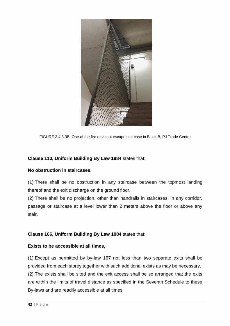
FIGURE 2.4.3.3B: One of the fire resistant escape staircase in Block B, PJ Trade Centre
Clause 110, Uniform Building By Law 1984 states that:
No obstruction in staircases,
(1) There shall be no obstruction in any staircase between the topmost landing
thereof and the exit discharge on the ground floor.
(2) There shall be no projection, other than handrails in staircases, in any corridor,
passage or staircase at a level lower than 2 meters above the floor or above any
stair.
Clause 166, Uniform Building By Law 1984 states that:
Exists to be accessible at all times,
(1) Except as permitted by by-law 167 not less than two separate exits shall be
provided from each storey together with such additional exists as may be necessary.
(2) The exists shall be sited and the exit access shall be so arranged that the exits
are within the limits of travel distance as specified in the Seventh Schedule to these
By-laws and are readily accessible at all times.

43 | P a g e
Clause 168, Uniform Building By Law 1984 states that:
Staircases,
(1) Except as provided for in by-law 194 every upper floor shall have means of egree
via at least two separate staircase.
(2) Staircases shall be of such width that in the event of any one staircase not being
available for escape purposes the remaining staircases shall accommodate the
highest occupancy load of any one floor discharging into it calculated in accordance
with provisions in the Seventh Schedule to these By-laws.
(3) The required width of a staircase shall be the clear width between walls but
handrails may be permitted to encroach on this width to a maximum of 75 millimetres.
(4) The required width of a staircase shall be maintained throughout its length
including at landings.
(5) Doors giving access to staircase shall be so positioned that their swing shall at no
point encroach on the required width of the staircase or landing.
Clause 202, Uniform Building By Law 1984 states that:
Pressurized system for staircase,
All staircases serving buildings of more than 45.75 metres in height where there is
no adequate ventilation as required shall be provided with a basic system of
pressurization-
(d) Where the mechanical system to prevent smoke form entering the staircase
shall be automatically activated by a suitable heat detecting device, manual or
automatic wet pipe sprinkle system

44 | P a g e
2.4.4 Horizontal Escape
The horizontal Escape is another escape that will route faster pathway for the
occupants to escape from the building when there is fire outbreak or any emergency
(Tavares, 2010).
Clause 171, Uniform Building By Law 1984 states that:
Horizontal exits,
(1) Where appropriate, horizontal exits may be provided in lieu of other exits.
(2) Where horizontal exits are provided protected staircases and final exits need only
be of a width to accommodate the occupancy load of the larger compartment or
building discharging into it so long as the total number of exit widths provided is not
reduced to less than half that would otherwise be required for the whole building.
2.4.5 Fire Resistant Doors
Fire resistant doors function as a barrier to block the spread of fire in the state of
closing and provide as a mean of escape when they are opened. It is specifically
designed to slow down the speed of passage of smoke and fire in various degrees
depends on its particular location in the building.
Moreover, automatic door closer hinge and devices were installed on the fire
resistant door to make sure that the fire door is always closed all the time. The closer
will automatically shut the fire door in the event of fire as to form a compartment and
avoid the spreading of fire to another spaces.

45 | P a g e
FIGURE 2.4.5A: Fire resistant door FIGURE 2.4.5B. Automatic door
in PJ Trade Centre closer hinge on fire resistant door
Clause 162, Uniform Building By Law 1984 states that:
Fire doors in compartment walls and separating walls,
(1) Fire doors of the appropriate FPR shall be provided.
(2) Openings in compartment walls and separating walls shall be protected by a fire
door having FRP in accordance with the requirements for that wall specified in the
Ninth Schedule to these By-laws.
(3) Openings in protecting structures shall be protected by fire doors having FRP of
not less than half the requirement for the surrounding wall specified in the Ninth
Schedule to these By-laws but in no case less than half hour.
(4) Openings in partitions enclosing a protected corridor or lobby shall be protected
by fire doors having FRP of half-hour.
(5) Fire doors including frames shall be constructed to a specification which can be
shown to meet the requirements for the relevant FRP when tested in accordance
with section 3 of BS 476:1951.

46 | P a g e
Clause 164, Uniform Building By Law 1984 states that:
Door closers for fire doors,
(1) All fire doors shall be fitted with automatic door closers of the hydraulically spring
operated type in the case of swing doors and of wire rope and weight type in the
case of sliding doors.
Clause 173, Uniform Building By Law 1984 states that:
Exit doors,
(1) All exit doors shall be openable from the inside without the use of a key or any
special knowledge or effort.
(2) Exit doors shall close automatically when released and all door devices including
magnetic door holders, shall release the doors upon power failure or actuation of the
fire alarm.
2.4.6 Fibre Reinforced Plastic Door
The Fibre Reinforced Plastic Door is made of Fibre Reinforced Plastic (FPR) which
louvers for ventilation purpose at high risk area such as Switch room. IT protected by
fire curtain and this kind of materials can last about half an hour fire rating.
The Fibre Reinforced Plastic Door is used at the electrical room which is located at
Basement 7.

47 | P a g e
FIGURE 2.4.6A: Fibre Reinforced Plastic Door of electrical room
2.4.7 Fire Lift
The fire lift built differently from other normal public lift with different features inside of
it. It is used by firemen in the event of fire while all the other public lifts are unable to
be used. All the public lifts are set to be off and remained at the Ground Floor Level
excepted the Fire Lift is on an active mood when it comes to the fire outbreak. In PJ
Trade Centre, the fire lift and others public lift are located at the same lobby for easy
accessible.

48 | P a g e
FIGURE 2.4.7A: Fire lift (lift bomba) of PJ Trade Centre
FIGURE 2.4.7B: Fire lift located together with public lift
49 | P a g e
Clause 124, Uniform Building By Law 1984 states that:
Lifts,
For all non-residential buildings exceeding 4 storeys above or below the main access
level at least one lift shall be provided.
Clause 154, Uniform Building By Law 1984 states that:
Emergency mode of operation in the event of mains power failure,
(1) On failure of mains power of lifts shall return in sequence directly to the designed
floor, commencing with the fire lifts, without answering any car or landing calls and
park with doors open.
Clause 243, Uniform Building By Law 1984 states that:
Fire lifts,
(1) In a building where the top occupied floor is over 18.5 metres above the fire
appliance access level fire lifts shall be provided.
(3) The fire lifts shall be located within a separate protected shaft if it opens into a
separate lobby.
(4) Fire lifts shall be provided as the rate of one lift in every group of lifts which
discharge into the same protected enclosure or smoke lobby containing the rising
main, provided that the fire lifts are located not more than 61 metres travel distance
from the furthermost point of the floor.

50 | P a g e
2.4.8 Lighting and Signage
2.4.8.1 Emergency sign and exit
Emergency exit signs are provided at the entire area around the evacuate pathways
of PJ Trade Centre in order to show the direction to the nearest exit and to ensure
the occupants are clear to the evacuation route. The emergency exit sign board is
green in colour with a graphic of a man running towards a door.
FIGURE 2.4.8.1A: Emergency exit sign

51 | P a g e
2.4.8.2 Emergency Exit Light
The emergency exit light is capable to illuminate and it is made of green fluorescent
light that is easier to be recognized by the occupant in the event of fire.
FIGURE 2.4.8.2A: Emergency exit light
Clause 172, Uniform Building By Law 1984 states that:
Emergency exit sign,
(1) Storey exits and access to such exits shall be marked by readily visible signs and
shall not be obscured by any decorations, furnishings or other equipment.
(2) A sign reading “KELUAR” with an arrow indicating the direction shall be placed in
52 | P a g e
every location where the direction of travel to reach the nearest exit is not
immediately apparent.
(3) Every exit sign shall have the word “KELUAR” in plainly legible letters not less
than 150 millimetres high with the principal strokes of the leters not less than 18
millimetres wide. The lettering shall be in red against a black background.
(4) All exit signs shall be illuminated continuously during periods of occupancy.
(5) Illuminated signs shall be provided with two electric lamps of not less than fifteen
watts each.
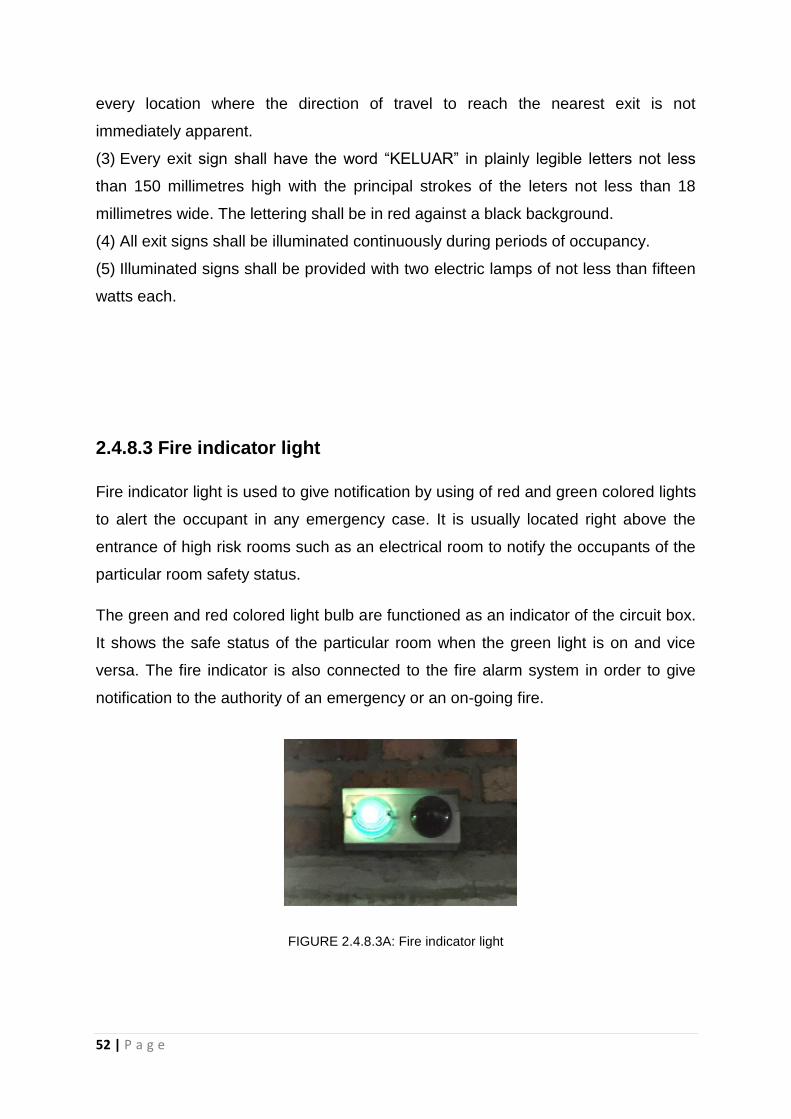
2.4.8.3 Fire indicator light
Fire indicator light is used to give notification by using of red and green colored lights
to alert the occupant in any emergency case. It is usually located right above the
entrance of high risk rooms such as an electrical room to notify the occupants of the
particular room safety status.
The green and red colored light bulb are functioned as an indicator of the circuit box.
It shows the safe status of the particular room when the green light is on and vice
versa. The fire indicator is also connected to the fire alarm system in order to give
notification to the authority of an emergency or an on-going fire.
FIGURE 2.4.8.3A: Fire indicator light

53 | P a g e
2.4.8.4 Safety and instruction signage
The safety notification signage and instruction were attached to the particular fire
resistant escape door by referring to the respective room and space.
FIGURE 2.4.8.4A: Safety and instruction signage
2.4.9 Analysis
Based on observation, PJ Trade Centre shows thoughtful planning and consideration
on the passive fire system and designed based on the UBBL 1984. The exits of PJ
Trade Centre are designed to be accessible in any consequences. However, we
found that the PJ Trade centre has no fire-rated wall installed in the building based
on the information given by the Service Management. Nevertheless, PJ Trade
Centre is a building still considered as safe and convenient.
54 | P a g e
3.0
MECHANICAL
VENTILATION AND AIR
CONDITIONING
SYSTEM

55 | P a g e
3.1 INTRODUCTION
Ventilation is a process of exchanging air, replacing air from outside or circulating air
within a space. It is important to prevent heat concentration (heat produced by
lighting, machine and human) and air humidity. Ventilation is also used to remove
carbon dioxide, unpleasant smells, excessive moisture and contaminants such as
airborne bacteria, smoke to replenish the indoor space with oxygen to maintain the
percentage of oxygen at 21%. The disposal of gas plays a crucial role in fire
prevention. Therefore, a building should ensure a good air circulation for comfort and
safety purpose.
Ventilation is divided into natural ventilation and mechanical ventilation. Natural
ventilation occurs when there is air difference. It can be achieved via operable
windows. However, mechanical ventilation is used when natural ventilation is not
appropriate. Without mechanical ventilation bringing in fresh air, contaminants, heat,
moisture, odours may be left in the building and will cause health problems. It
circulates fresh air by using fans, ductwork rather than relying on openings. Air is
being pushed inwards or outwards by motorised fan, resulting in different air
pressure state, and thus allowing the air to circulate around the building in a
mechanical way.
Malaysia poses tropical climate, which is generally sunny throughout the year and
has high precipitation rate every month. Hence, the thermal comfort in a building is
having filtered supplied air, with a temperature range of 22°C to 27°C and relative
humidity of 55% to 70%. In this hot and humid climate, air-conditioning system as
part of the ACMV (Air-Conditioned and Mechanical Ventilation) system is one of the
crucial building service in most of the buildings typically in Malaysia. Differing from
mechanical ventilation, air-conditioning is considered as an active system that
removes heat from the air inside the room and release the collected heat to the air
outdoors. The role of air conditioning do more than providing acceptable indoors air
quality and ensuring thermal comfort. It prevents smoke, dust and haze from
outdoors to protect human health and some are sued as cooling devices to chill
electrical appliances or machineries for better performance.

56 | P a g e
3.2 LITERATURE REVIEW
3.2.1 Mechanical Ventilation
HVAC, known as Heating, Ventilation, and Air-Conditioning System, serves the main
purpose of maintaining good indoor quality with adequate ventilation to provide
comfort and ventilation for users without harms to the built environments. Ventilation
is simply defined as the process of changing air in open spaces, semi-open spaces,
and enclosed spaces to continuously provide fresh air or free movement of air in that
particular space.
3.2.2 Air Conditioning System
The definition of air-conditioning system is to control the temperature, humidity, air
cleanliness and air movement and heat radiation with mechanical means, to achieve
human thermal comfort. The function of the air conditioning system is to remove the
heat from the air inside the room and release the collected heat into the air outdoors.
The air temperature should be between 19 and 23 degree Celsius and relative
humidity within the 40-60% band.

57 | P a g e
3.3 MECHANICAL VENTILATION
3.3.1 Introduction
Mechanical ventilation system is a system used to circulate fresh air using ducts and
fans rather than relying on airflow through small holes or cracks on a home wall, roof
or windows. The mechanical ventilation system has been used widely since the early
twentieth century, fan assisted movement of air has largely substituted the passive
air ventilation system owing to the requirement of huge indoor space demands.
These are the components of the mechanical system:
Fans:
Provide the motive power for air movement by imparting static energy or pressure
and kinetic energy or velocity. A fan’s capacity for air movement depends on its
characteristics such as type, size, shape, number of blades and speed. There are
four categories of fan suitable for efficient air movement in the mechanical ventilation
system, which are cross-flow, propeller, axial flow and centrifugal.
Filters:
Filters are used to remove suspended particles, contaminants and odours. The filters
are usually installed at the inlet grille.
Ductworks:
The function of the ductworks is to channel indoor air out from the room or vice versa.
It is usually produced in circular, square or rectangular cross-sections in several
different materials.
Fire Dampers:
Fire dampers are required in the case of fire occurrence, preventing the fire from
spreading from one room to another. It is usually placed at the compartment wall.
Diffusers:
Diffusers range from simple perforated plated and grilles to the more complex and
efficient coned air distributors. The grille and diffuser are located at the edge of the
ductwork where the air can easily released into the rooms.

58 | P a g e
3.3.2 Components Of System involved in Mechanical
Ventilation System
3.3.2.1 Ducting System
In PJ Trade Centre, ducting systems are exposed and visible where the exposure of
the ducting systems is to implement to the idea of modernity and has aesthetic visual
quality. The function of ducting systems requires the exchange of indoor air, which in
takes the warm air from the spaces and distribute to the Air Handling Unit (AHU).
The ducting system consists of ducts, diffusers, return air grilles, and fire dampers.
All the ducting systems in PJ Trade Centre are insulated to reduce heat loss and
minimise the installation cost. In Figure 3.3.2.1A, branches of the ducting system
from AHU extend throughout the basement parking to absorb the exhaust gases
expelled by the vehicles. The noise pollution is produced when the operator of the
system is switched on. The ducts used are in rectangular shapes and 1m x 1.5m in
size range.
At the back of AHU, there are Axial Fans to expel the exhaust gases from AHU via
ducting. It consists of aerofoil cross sections blades mounted on a motor driven
central shaft as shown in Figure 3.3.2.1B.
FIGURE 3.3.2.1A: Ductwork at the basement parking in a protected shaft

59 | P a g e
Clause 156, Uniform Building By Law 1984 states that:
Protected shafts as ventilating duct,
(1) If a protected shaft serves as, or contains, a ventilating duct –
(a) The duct shall be fitted with automatic fire dampers together with or without
subducts as Australian Standard 1668: Pt. 1:1974, so constructed at such
intervals and in such positions as may be necessary to reduce, so far as
practical, the risk of fire spreading from a compartment to any other
compartment, or such other provision shall be made as will reduce such risk so
far as practicable; and
(b) The duct shall not be constructed of, or lined with, any material which
substantially increases such risk.
FIGURE 3.3.2.1B: Axial fan connecting ductworks to develop high-pressure and to move air through
the long sections of ductwork
The kitchen exhaust fan is for kitchen ventilation purpose. This system is only
applicable to the F&B tenants in PJ Trade Centre. Tenant kitchens are provided with
one set of black steel exhaust duct and G.I. fresh air ducting (Figure 3.3.2.1C) which
is terminated by one volume control damper to adjust the amount of airflow within the
tenants. Non-return damper is also installed at all exhaust outlets to avoid flowing
back of smoke.
Circular fan housing
Impeller

60 | P a g e
FIGURE 3.3.2.1C: Black steel exhaust duct at the back lane outside of the kitchen
Clause 99, Uniform Building By Law 1984 states that:
Cooking facilities in residential buildings (2), where a common vertical kitchen
exhaust riser is provided, the riser shall be continued up to a mechanical floor or roof
for discharge to the open, and shall be constructed with fire resisting material of at
least 2 hours rating with BS476: Part 3.
3.3.2.2 Extract Ventilation
In PJ Trade Centre, the extract ventilation has been set up in the fire pump room
equipped with ductwork that is attached to the extract fan in order to provide fresh air
in the room (Figure 3.3.2.2A). It also acts as a prevention of cross-flow odours,
smoke and noise through the extract fan.

61 | P a g e
FIGURE 3.3.2.2A: Extract ventilation at the basement parking to extract exhaust gases released by
vehicles
FIGURE 3.3.2.2B: The process of extract ventilation system
SOURCE: Building Services, Technology and Design Book, Roger Greeno
62 | P a g e
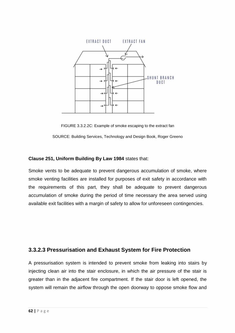
FIGURE 3.3.2.2C: Example of smoke escaping to the extract fan
SOURCE: Building Services, Technology and Design Book, Roger Greeno
Clause 251, Uniform Building By Law 1984 states that:
Smoke vents to be adequate to prevent dangerous accumulation of smoke, where
smoke venting facilities are installed for purposes of exit safety in accordance with
the requirements of this part, they shall be adequate to prevent dangerous
accumulation of smoke during the period of time necessary the area served using
available exit facilities with a margin of safety to allow for unforeseen contingencies.
3.3.2.3 Pressurisation and Exhaust System for Fire Protection
A pressurisation system is intended to prevent smoke from leaking into stairs by
injecting clean air into the stair enclosure, in which the air pressure of the stair is
greater than in the adjacent fire compartment. If the stair door is left opened, the
system will remain the airflow through the open doorway to oppose smoke flow and

63 | P a g e
prevent contamination of the stair enclosure. In PJ Trade Centre, this system is
applied in every protected stairways area.
FIGURE 3.3.2.3A: Location of centrifugal fan, fire damper and circular ductwork
The pressurisation system has three main components:
(i) Supply Air – air is injected into the area that is protected
(ii) Pressure Relief – to avoid overpressure when doors are closed
(iii) Air Release – air and smoke are released from the adjacent fire area
Due to these components, it forms a positive pressure difference to prevent smoke
from entering lobbies and staircase area.

64 | P a g e
FIGURE 3.3.2.3B: A component diagram of mechanical ventilation
The distance of supply air fan from exhaust louvers should be 5m and another 5m to
the wall, reducing the possibility of smoke shifting into the air supply shaft. It is a
provision to place a propeller fan in the void of the external wall as shown in Figure
3.3.2.3C. It is placed in lift motor room to release unpleasant odour released by the
machineries. It does not require any ductwork where it is able to stand on its own
with steel or plastic blades mounted at a right angle to a central boss.
FIGURE 3.3.2.3C: Propeller fan in the lift motor room

65 | P a g e
There are also fire damper plates (Figure 3.3.2.3D) provided in that particular space
other than emergency staircase in order to allow smoke release.
FIGURE 3.3.2.3D: Fire damper at the emergency staircase
The installation of motor-fans at the basement to suck air into the stairwell is
necessary to avoid infiltration of smoke in the event of fire. The outside air is
captured throughout a cover up that has a particle filter (Figure 3.3.2.3D).
FIGURE 3.3.2.3D: Filter in the water pump room

66 | P a g e
Clause 202, Uniform Building By Law 1984 states that,
Pressurised system for staircase, all staircase serving buildings of more than 45.75
metres in height where there is no adequate ventilation are required shall be
provided with a staircase pressurisation system designed and installed in
accordance with MS1472.
FIGURE 3.3.2.3E: Centrifugal fan on the rooftop
Centrifugal fan in PJ Trade Centre is placed on the rooftop (Figure 3.3.2.3E) is to
efficiently move large or small quantities of air over a wide range of pressure.

67 | P a g e
3.4 AIR CONDITIONING SYSTEM
3.4.1 Introduction
Air conditioning system is the process of altering the properties of air primarily
temperature and humidity to more comfortable conditions, typically with the aim of
distributing the conditioned air to an occupied space to improve thermal comfort and
indoor air quality. In particular to maintain a cool atmosphere in warm conditions,
especially in a country of tropical climate like Malaysia. Conditioned air means the
clean and odor-free air. Controllable temperature, humidity, and movement of the air
are within certain comfort ranges to achieve human thermal comfort.
3.4.2 Type of Air Conditioning System
There are four types of air conditioning system which are room air conditioner
(window Unit), Split unit air conditioning system, Package Unit air conditioning
system, Centralized or Plant air conditioning system. The type of air conditioning
system used in Block B (Bata) is split unit air conditioning system. Whereas, For
Block A, Block C and Block D (Based on the Figure 6.13), used centralized unit air
conditioning systems.
FIGURE 3.4.2A: The yellow zones indicated area that used split unit air conditioning system. The
green zone indicated area that used centralized unit air conditioning system

68 | P a g e
FIGURE 3.4.2B: Levels that used unit air conditioning system in Block B
FIGURE 3.4.2C: The circle indicate the outdoor unit are well planned at minor observing area

69 | P a g e
FIGURE 3.4.2D: Drawing shown the arrangement of outdoor unit used at Block B
In this report, we will look into the air conditioning system in Block B. The reason
Block B utilizes split unit air conditioning system is because it is co-owned by a few
companies whereas as Block A is sole owned by same owner ( Lembaga Hasil).
3.4.2.1 Room air conditioner (Window Unit)
Room air conditioner is the simplest form of air-conditioning system and suitable only
for a small room. It is usually installed at window openings or wall. It can be divided
into 2 compartments: the room side and the outdoor side separated by an insulated
partition.

70 | P a g e
FIGURE 3.4.2.1A: Components of room air conditioner
SOURCE: http://www.fixitclub.com/heating-cooling-repairs/room-air-conditioner-repair/
3.4.2.2 Package Unit air conditioning system
The package unit air conditioning system are used for the cooling capacities in
between window or split air conditioners and central air conditioning systems. The
package air conditioners are available in air conditioning capacities of 3,5,7,10 and
15 tons. These conditioning systems are commonly used in places like small halls,
restaurants, homes, etc.
FIGURE 3.4.2.2A: Package unit air conditioners in home

71 | P a g e
3.4.2.3 Centralized/ Plant air conditioning system
Centralized air conditioner is the conditioning system used in Block A, C and D. They
circulate cool air through a system of supply and return ducts. Supply ducts and
registers transfer cooled air from the air conditioner into the room. This cooled air will
becomes warmer as it circulates through the home and gain heat from the room
temperature. The warmer air will flows back to the central air conditioner through
return ducts and registers. Centralized air conditioner is suitable for Block A,C and D
because it is easier to manage and can effectively circulate cool air throughout the
whole office block. Centralized air conditioner are easy to operate and the system is
conveniently controlled by a simple console that can be scheduled to run at certain
times and temperatures. It also minimizes the energy wastage and noise (condenser
and compressor are located away from the working area).
FIGURE 3.4.2.3A: Components of Centralized air conditioning system
SOURCE: http://energy-models.com/hvac-centrifugal-chillers

72 | P a g e
3.4.2.3 Split unit air conditioning system
Split unit air-conditioner is a widely used air conditioning system nowadays. This
system comprises of two parts: The outdoor unit and the indoor unit (Figure 3.4.2.3A
& 3.4.2.3B). The outdoor unit (The compressor) is placed at the building facade. It
comprises of components like Compressor, condenser and expansion valve. The
indoor unit is placed inside the room. The components comprises of a evaporate
cooling coil and a cooling fan. A split air conditioner is suitable for Block B to fulfill the
requirement for different user and minimize energy consumption through the
controlled air conditioner unit. Split unit air conditioner used in Block B has does not
require constant supply of fresh air to renew the existing indoor air quality. It
functions by recycling and recirculating the existing indoor air. A multi-split unit
consists of multiple indoor units with one compressor.
FIGURE 3.4.2.3A: Indoor Unit found in PJTC discussion room
FIGURE 3.4.2.3B: Outdoor unit located outside of the building

73 | P a g e
3.4.3 Components of the split unit air conditioning system
A split air conditioning system consists of two separate components, the outdoor unit
and indoor unit. The outdoor unit also known as a Compressor, initiates the cooling
process. The indoor unit has an evaporator and fan. All the components are
connected with a set of electrical wires and tubing to transport the air and to
discharge the waste water and heat.
3.4.3.1 Outdoor unit
The outdoor unit is the noisiest part of the air conditioner. Thus, it must be placed
outside the room, preferably in the open space over the compressor and condenser.
Moreover, the outdoor with good air circulation needed to be mounted on a strong
structure to support its vibration force. There should be obstacle free around the
outdoor unit that would interrupt the operation and passage of hot air. Inflammable
items should not be placed around the outdoor unit.
FIGURE 3.4.3.1A: Components in split unit air conditioner

74 | P a g e
Components in Outdoor unit:
Evaporator:
The evaporator helps to absorbs the heat taken from the surrounding and replaces it
with cooled air
Compressor:
Compressor is the most important part of air conditioner. It compresses the
refrigerant from low pressure ( low temperature) to high pressure ( high temperature)
before sending it to the condenser by external power. This conversion raises the
boiling point to higher temperature levels, facilitating elimination of the heat brought
by the outdoor air.
Condenser:
The condenser used in the outdoor unit of split air conditioners is the coiled copper
tubing with one or more rows depending on the size of the air conditioning unit and
the compressor. The high temperature and high pressure refrigerant ( low
temperature) from the compressor comes in the condenser where it has to give up
the heat. The tubing is made up of copper since it rate of conduction of heat is high.
The condenser is also covered with the aluminum fins so that the heat from the
refrigerant can be remove at fast speed. In air cooled condensers, the metallic
surfaces cool the gas which changes status and turns to liquid. In case of water-
cooled condensers, it is the circulation of the water that produces the same cooling
effect.
Indoor fan:
It exhausts air from the indoor environment and conveys it though the evaporator:
the air is now cool and distributed back into the environment.
Outdoor fan:
This causes the air to circulate through the condenser in order to cool the refrigerant.
Electrical parts:
Electrical and electronic components needed by the various air conditioner functions

75 | P a g e
Capillary tube:
The capillary tube is a simple refrigerant liquid metering device that regulates the
flow of refrigerant from the incoming high pressure side( from the compressor or
condenser) into the low pressure side ( In the Cooling Coil)
Expansion valve:
The expansion valve is usually copper capillary tubing with several rounds of coils. In
the split air conditioners of bigger capacities thermostatic expansion valve is used
which is operated electronically automatically. The high pressure and medium
temperature refrigerant leaves the condenser and enters the expansion valve, where
its temperature and pressure drops suddenly.
3.4.3.2 Indoor unit
FIGURE 3.4.3.2A: Wall mounted type FIGURE 3.4.3.2B: Ceiling mounted type
The indoor unit must be placed in a strategic position. The location of indoor unit
must allow air distributed evenly and easily distribute throughout the room.

76 | P a g e
3.4.4 Operation of system
The split unit air conditioning unit pumps heat from outside and converting it to cool
air once it passes through the refrigeration cycle. During refrigerant cycle, the
refrigerant will undergo the phase changes, pressure changes and temperature
changes.
FIGURE 3.4.4: Operation system of split unit air conditioner
SOURCE: http://inspectapedia.com/aircond/HVAC_Blower_Fan.php
In the article entitled “ How does a Split Air Conditioner Work?” explains about the
process of the split air conditioner. The process is start with the compressor that is
controlled by the thermostat inside. As the thermostat detects warm air, it activates
the compressor outside. The compressor circulates a refrigerant gas, increasing the
pressure and temperature of the refrigerant as it compresses it through a series of
pipes. The refrigerant then moves to the condenser for further processing.
( DoltYourself. (n.d).)

77 | P a g e
In the condenser, the cooling system removes heat from the high pressure gas. The
gas undergoes condensation phases and turns a liquid. This chilled liquid is pushed
through tubing indoors until it reaches the evaporator system.
Inside the building, the evaporator fan collects warm air and passes it through a
chamber containing chilled liquid refrigerant. The fan system then blows the cooled
air back into the room, lowering the overall temperature of the space. If the
thermostat still detects air that is warmer than desirable temperature, the process
continues and the refrigerant and any excess heat that remains in the system are
passed back outdoors to the compressor in order to begin a new cycle.
3.4.5 UBBL requirements of Related Regulations
Clause 41, Uniform Building By Law 1984 states that:
Mechanical Ventilation and Air Conditioning,
(1) where permanent mechanical ventilation or air conditioning is intended, the
relevant building by-laws relating to natural ventilation, natural lighting and
heights of rooms may be waived at the discretion of the local authority.
(2) Any application for the waiver of the relevant by laws shall only be considered if
in addition to the permanent air conditioning system there is provided alternative
approved means of ventilating the air conditioned enclosure, such that within
half-an-hour of the air conditioning system failing, not less that the stipulated
volume of fresh air specified hereinafter shall be introduced into the enclosure
during the period when the air-conditioning system is not functioning.
(3) The provisions of the Third Schedule to these By laws shall apply to buildings
which are mechanically ventilated or air-conditioned.
(4) Where permanent mechanical ventilation in respect of lavatories, water closets,
bathrooms or corridors is provided for and maintained in accordance with the
requirements or the Third Schedule to these By-laws, the provisions of these By-

78 | P a g e
laws relating to natural ventilation and natural lighting shall not apply to such
lavatories, water-closets,bathrooms or corridors.
Clause 41, Uniform Building By Law 1984 states that:
Mechanical Ventilation and Air Conditioning,
(1) where permanent mechanical ventilation or air conditioning is intended, the
relevant building by-laws relating to natural ventilation, natural lighting and
heights of rooms may be waived at the discretion of the local authority.
(2) Any application for the waiver of the relevant by laws shall only be considered if
in addition to the permanent air conditioning system there is provided alternative
approved means of ventilating the air conditioned enclosure, such that within half-
an-hour of the air conditioning system failing, not less that the stipulated volume
of fresh air specified hereinafter shall be introduced into the enclosure during the
period when the air-conditioning system is not functioning.
(3) The provisions of the Third Schedule to these By laws shall apply to buildings
which are mechanically ventilated or air-conditioned.
(4) Where permanent mechanical ventilation in respect of lavatories, water closets,
bathrooms or corridors is provided for and maintained in accordance with the
requirements or the Third Schedule to these By-laws, the provisions of these By-
laws relating to natural ventilation and natural lighting shall not apply to such
lavatories, water-closets,bathrooms or corridors.

79 | P a g e
3.4.6 Analysis
In conclusion, we think that air-conditioning system used in PJ Trade centre is well
planned to meet the client’s requirement and also to ensure comfort for the users.
For Split unit air-conditioning system used in Block B, the designer and mechanical
worker successfully applied the system and solved the disadvantages. As most of
the outdoor units are well planned at minor observing area to enhance the aesthetic
appeal and away from the services area to minimize the noise and simplify utility
connections.

80 | P a g e
4.0
Mechanical
Transportation
81 | P a g e
4.1 INTRODUCTION
Circulation is an important factor when it comes to designing a building. The general
purpose of mechanical transportation is to ease the movement of users throughout
the whole building space efficiently and safely. This section of case study is to
identify and analyze the mechanical transportation systems used in our case study
building, PJ Trade Centre. Complimenting to the paradigm of PJ TRADE CENTER,
“the use of simple local materials and local construction methods to create an office
development that is suited to the local culture, climate and context” the building
employs naturally ventilated lift lobbies and staircases. Thus, it only utilizes lifts
systems throughout the whole building.

82 | P a g e
4.2 LITERATURE REVIEW
The decisions made by a designer for vertical transportation method is important as
it accounts for 10% to 15% of the construction budget, a determining factor in
building shape, core layout, and the operation cost. (Grondzik & Kwok, 2015). Other
factors such as fire safety, security and noise are also dependent on the choice of
vertical transportation. Therefore, a proper consultation with the specialist in early
stages is necessary as numerous factors determine an ideal operation and comfort
of vertical transportation in a building.
Lifts
Lifts are a common method of vertical transportation in multistory buildings. There
are generally 2 types of lifts commonly used. They are:
Electrical lifts (traction lifts / machine room-less lifts)
Hydraulic lifts.
4.2.1 Electric Lift
An electric lift can be divided into 2 types – traction lifts / machine room-less lifts.
4.2.1.1 Traction Lift
A traction lift’s transmits lifting force to the hoist ropes of an lift by friction between
the groves in the machine drive sheave and the hoist ropes. The ropes are
connected from the car to the counter weight and wrapped over the machine drive
sheaves. The weight of both car and counterweight ensures the seating of ropes in

83 | P a g e
the groove. A traction lift’s machine is further divided into – gear / gearless traction
lift. A gearless traction lift which consists of a DC or AC motor with the shaft directly
connected to a brake wheel and driving sheave. A geared traction lift has a worm
and gear interposed between the driving motor and the hoisting sheave.
FIGURE 4.2.1.1A: Components of a gearless traction lift
4.2.1.2 Machine Room-less Lifts
As the name suggests, a machine room-less lift does not have a dedicated machine
room above the lift shaft. The machines sit in the override space and are accessed
from the top of the lift car. The control box is located in a control room that is
adjacent to the lift shaft on the highest landing and within 150ft of the machine. It is
designed for buildings between 2 – 30 floors.
84 | P a g e
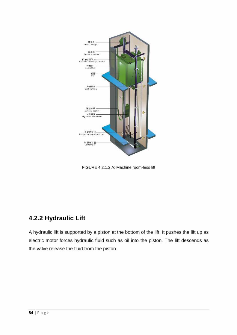
FIGURE 4.2.1.2 A: Machine room-less lift
4.2.2 Hydraulic Lift
A hydraulic lift is supported by a piston at the bottom of the lift. It pushes the lift up as
electric motor forces hydraulic fluid such as oil into the piston. The lift descends as
the valve release the fluid from the piston.

85 | P a g e
FIGURE 1.2.2: Hydraulic lift
4.2.3 Performance of Lift
An ideal performance of a lift is determined by its, waiting interval, acceleration
speed, braking system, accuracy of auto leveling at landings of each floors, loading
and unloading intervals. Besides that, the operations of doors, types of floor finishing,
usage of clear direction indicators, emergency safety and types of lighting will
determine its user comfort while using the lift.

86 | P a g e
4.3 Placement of Lift
The location of lifts should be carefully planned to be within the proximity of the
entrances so that it is easily accessible to all building spaces. Ideally a maximum
walking distance of 45m to lift lobby is preferred. Staircases should be taken into
account in the case of lift breakdown.
Clause 124, Uniform Building By Law 1984 states that:
For all non-residential buildings exceeding 4 storeys above or below the main access
level at least one lift shall be provided.
In compliance with the UBBL clause as stated above, as PJ TRADE CENTER
contains 4 towers (Block A – D) and 2 zones (basement floors and office and
commercial floors), the lifts in PJ TRADE CENTER are zoned and grouped into 3
sections (FIGURE ) as stated below:
4 groups of 2 passenger lifts car to 7 basements floors
4 groups of 5 passenger lifts car to 21 office and commercial floors
4 groups of fireman lifts to all floors
Zoning and grouping the lifts are able to provide every passenger with equal lift
service, reducing waiting time and reducing installation cost.

87 | P a g e
FIGURE 4.3A: Zoning and grouping of lifts system
FIGURE 4.3B: Shows the location of passenger lifts that serve basement 1 – basement 7 for all 4
blocks

88 | P a g e
FIGURE 4.3C: Shows the location of passenger lifts that serve level 1 to level 21 for Block B
4.3.1 Lift Lobby
The design of lift lobby should have adequate spaces to ensure smooth traffic flow
during peak hours and unobstructed the lift landing. Building directory can be
provided as direction indicators to building users.

89 | P a g e
FIGURE 4.3.1A: Building directory at 1F lift lobby of PJTC
FIGURE 4.3.1B: Natural ventilation as unique design feature of lift lobby at PJ TRADE CENTER.

90 | P a g e
4.3.2 Fire Safety
4.3.2.1 Protected Lobby
Clause 152, Uniform Building By Law 1984 states that:
(1) Every opening in a lift shaft or lift entrance shall open into a protected lobby
unless other suitable means of protection to the opening to the satisfaction of the
local authority is provided. These requirements shall not apply to open type
industrial and other special buildings as may be approved by the D.G.F.S
Complying with UBBL section 152 all lift lobby should also be connected to a
protected lobby as stated in Figure 4.3.2.1A.
.
FIGURE 4.3.2.1A: Plan indicating location of protected lobby

91 | P a g e
FIGURE 4.3.2.1B: Photo of basement lift lobby at PJ TRADE CENTER. Automatic roller shutter would
be close down during fire evacuation
4.3.2.2 Sprinklers & Smoke Detectors
Clause 153, Uniform Building By Law 1984 states that:
(1) All lift lobbies shall be provided with smoke detectors.
Complying to UBBL Section 153.(1) all lift lobby should be equip with smoke
detectors which automatically triggers the fire alarm during fire emergency. In
addition to that, sprinkles system are also provided in every lift lobbies at PJ TRADE
CENTER. Once the fire emergency has been activated:
1. All lift shall return to their designated landing except for the fireman lift
2. All car and hall calls are canceled
3. Passenger in the car should be informed of the situation
4. Travelling cars are to stop at the immediate next landing

92 | P a g e
FIGURE 4.3.2.2A: Photo showing smoke detector and sprinkles (highlighted) at lift lobby
4.3.2.3 Fireman Lift’s Switch and Emergency Exit Indicator
Fire lift switch and emergency exit indicator are to be provided to at lift lobby at every
floor. Once the toggle switch has been activated, designated fireman lift will travel to
the fire recall floor to transport passengers to the designated landing for evacuation.
The lift will then remove from normal service and no longer accept hall calls.
FIGURE 4.3.2.3A: Photos showing fireman lift's switch and emergency exit indicator @ B1

93 | P a g e
4.3.3 Call Button & Hall Lantern
The car and lobby signals and lanterns should be designed to meet their basic
function while considering the need of the disable. In PJ TRADE CENTER, both the
call button and hall lantern are incorporated, located adjacent to the related lift door.
A call button should indicate the direction of travel with Braille imprint and lights up
once a call has been placed.
A Hall lantern must indicate the direction of travel of an arriving lift and its present
location. In order to facilitate waiting process and as an aid for passenger with sight
impairment, an audible signal should announce the arrival of lift car.
FIGURE 4.3.3A: Photo showing location of call button and hall lantern @ lift lobby of PJTC

94 | P a g e
FIGURE 4.3.3B: Blow-up photo of call button and hall lantern

95 | P a g e
4.4 OPERATION OF LIFTS
A principal components of a geared traction lift consists of car, cables, lift machine,
control equipment, counter weight, hoistway, rails, penthouse, and pit.
Our case study building, PJ TRADE CENTER utilizes traction lifts as higher travel
speeds and larger load carrying capacity are needed to serve all 21 office and
commercial floors and 7 basements.
Specification of traction machine @ PJ TRADE CENTER
Capacity: 1365kg (20 pax) (passenger);
1635kg (24 pax) (fireman)
Rise distance: 65m (passenger); 98m (fireman)
Motor power: 21kW (passenger); 25kW (fireman)
Speed: 2.50 m/s
4.4.1 Gearless Traction Lift
A gearless traction machine as chosen as a rise of more than 76m and travel speed
of above 2.3m/s is required. As compared to a geared traction machine, a gearless
traction machine has higher efficiency, quieter operation, less maintenance, longer
life span and smoother and higher travelling speed.
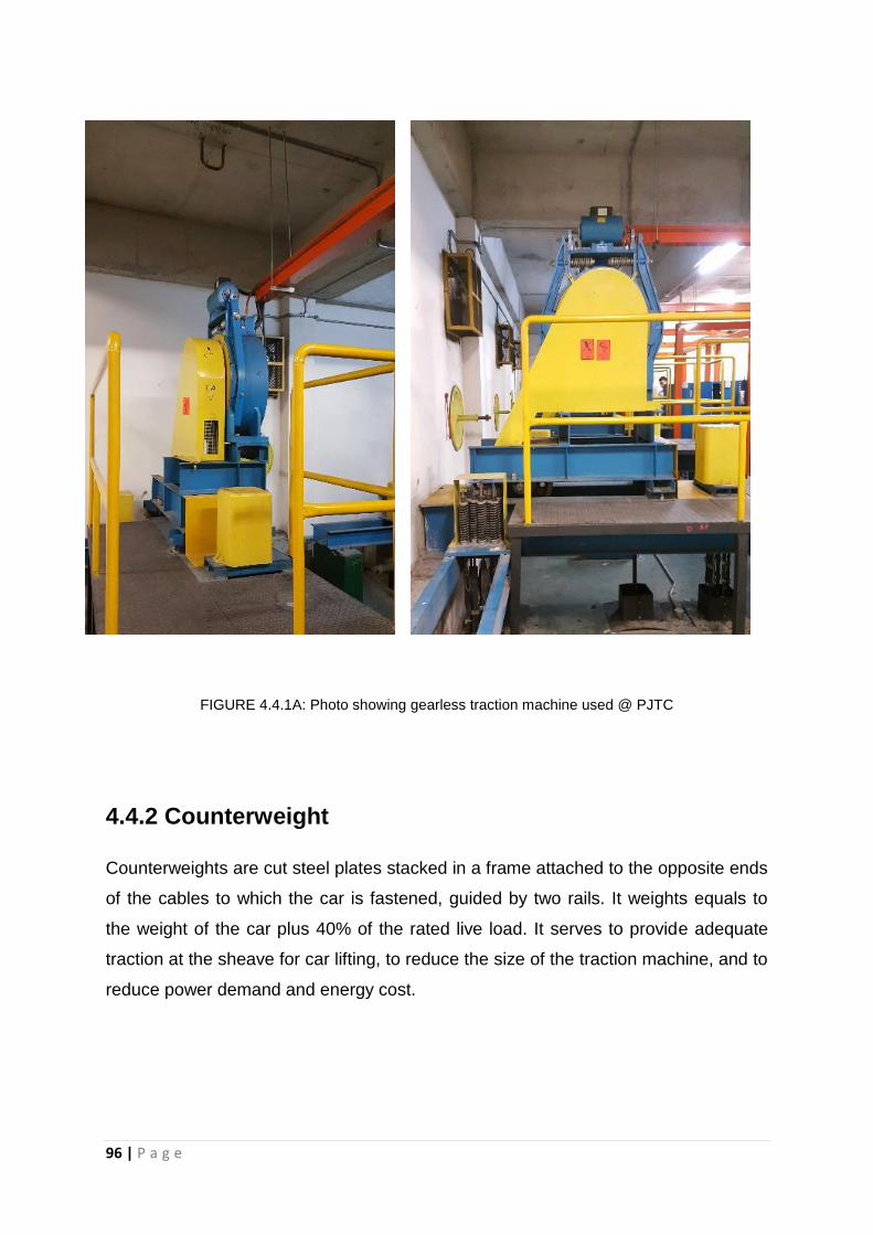
96 | P a g e
FIGURE 4.4.1A: Photo showing gearless traction machine used @ PJTC
4.4.2 Counterweight
Counterweights are cut steel plates stacked in a frame attached to the opposite ends
of the cables to which the car is fastened, guided by two rails. It weights equals to
the weight of the car plus 40% of the rated live load. It serves to provide adequate
traction at the sheave for car lifting, to reduce the size of the traction machine, and to
reduce power demand and energy cost.

97 | P a g e
4.4.3 Cables
The cables that are connected to the top beam of lift to carry the weight of the car
and its live load are made of a group of steel wires. In PJ TRADE CENTER, eight
cables are placed in parallel to the lift car.
4.4.4 Lift Car
A lift car is a fire resisting cage fastened to a structural frame. The top of the
structural frame is then fastened to the lift cables. The side member of the car is
guided by guide shoes which guide its vertical movement along the lift shaft. In
general, the car is provided with safety doors, operating-control equipment, floor-
level indicators, lighting and ventilation system and emergency exit.
FIGURE 4.4.3A: Eight steel cables used for the lift

98 | P a g e
The internal dimension of a passenger lift car in PJ TRADE CENTER is 2000mmW x
1550mmD which permits the turning of a wheelchair. It is cladded in stainless steel
finish with overburnt brick flooring that extends from the exterior.
FIGURE 4.4.4A: Plan of passenger lift car

99 | P a g e
FIGURE 4.4.4B: Photos showing the exterior of lift car
FIGURE 4.4.4C: Photos showing overburnt brick flooring of lift car

100 | P a g e
In order to accommodate higher loading capacity and at the same time double its
function as a loading and unloading lift, the size of its fireman lift is bigger than its
passenger lift. Besides that, Figure 4.4.4D shows the interior wall of the lift car is
padded to protect its finishes from scratches.
FIGURE 4.4.4D: Interior of a fireman lift car

101 | P a g e
4.4.4.1 Lift Door
Clause 152, Uniform Building By Law 1984 states that:
(1) Landing doors shall have a FRP of not less than half the FRP of the hoistway
structure with a minimum FRP of half hour
(2) No glass shall be used for in landing doors except for vision in which case any
vision panel shall or be glazed with wired safety glass, and shall not be more than
0.0161 square meters and the total area of one of more vision panels in any
landing door shall be not more than 0.0156 square meters.
(3) Each clear panel opening shall reject a sphere 150 millimeters in diameter.
(4) Provision shall be made for the opening of all landing doors by means of an
emergency key irrespective of the position of the lift car
The door of the lift at PJ TRADE CENTER are power-operated and are synchronized
with the leveling controls so that the doors are fully opened by the time a car comes
to a complete stop at landing. With reference to Figure 4.4.4.1A a centre-opening
door with clearance of 1100mmW is used to the facilitate passenger transfer time,
disabled friendly and permits loading and unloading without undue passenger
contact.
4.4.4.2 Lift Car Control
In general, every car panel should be equip with full access buttons for call registry,
door-open, alarm, emergency stop, firefighter control, door-close button and
intercom. Controls that do not concern the passenger should be locked in another
component.
Both lift car control at PJ TRADE CENTER lacks:
An intercom device that permits communication with the building control office
and emergency fireman service
Emergency stop button

102 | P a g e
Alarm button for lift that serves 1F-21F
FIGURE 4.4.4.2A: Lift car control for lift B1-B7 and 1F to 21F
4.4.4.3 Lighting & Ventilation
MS1525 states that lighting in a lift car must provide a suitable visual environment
with recommended average illuminance of 100 Lux. In addition to that, they also
states that a lift car should have an adequate force ventilation of <10 air change per
hour when it is in use. Fans and blowers should be securely fastened outside and
above the lift car hidden from sight of the passenger.
The lighting and ventilation system for PJ TRADE CENTER is on 24 hours.

103 | P a g e
In the case of lift breakdown, emergency lighting will be activated for 3 hours.
Besides that, ventilation holes located at the bottom of the lift car will provide air
circulation throughout the lift.
FIGURE 4.4.4.3A: Ventilation holes at the bottom of lift car
4.4.4.4 Emergency Railing
Lift rails lines the interior perimeter of the lift car. The grab bars must be provided on
both sides and rear of the lift car with 900mm to 1200mmH from floor finish level.
(International Organization for Standardization, 2004) This allows the railings to be
grab by passenger from any direction during emergency break.
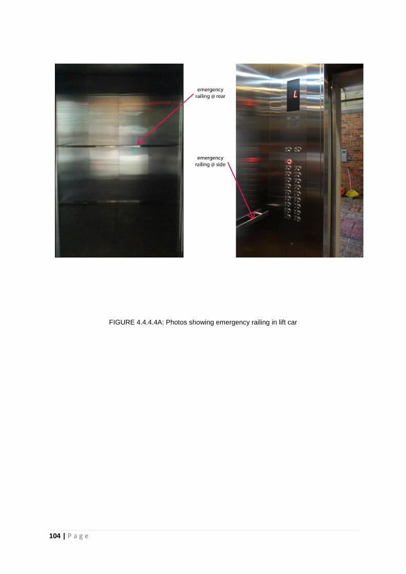
104 | P a g e
FIGURE 4.4.4.4A: Photos showing emergency railing in lift car

105 | P a g e
4.5 SAFETY DEVICES
The protection of its passengers during normal operation is ensured by a number of
safety features as stated below:
Main brake mounted directly on the shaft of the lift machine. The lift is first
slowed by dynamic braking of the motor and the brake then clamps on to the
brake drum, thus holding the car still.
A centrifugal governor or an electronic speed control sensor cuts the power of
the traction motor and sets the brake in case of limited over-speed. If over-
speeding continues, it activates two safety rail clams, mounted at the bottom
of the car.
Rope system in an lift has to be built with multiple spare ropes (4-8 ropes).
This is so that during an event where the ropes snaps, the spare ropes will
continue to hold the lift until it gets replaced.
Oil or spring buffers placed In the pit acting as a cushion to reduce the impact
of a falling car

106 | P a g e
4.6 MACHINE ROOM
The machine room of PJ TRADE CENTER is placed in an enclosed room at the roof
top directly above the hoistway. This minimizes the length of cables required and
optimizing its efficiency. This will also reduce the noise transmission to other office
levels below. As these machines required constant maintenance, it is furnished with
overhead trolley beam to ease the procedure of moving the machine.
FIGURE 4.6A: Plan of machine room at PJ Trade Centre
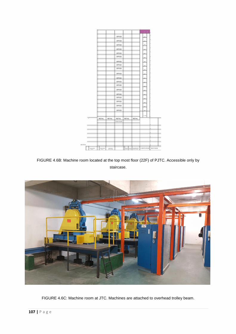
107 | P a g e
FIGURE 4.6B: Machine room located at the top most floor (22F) of PJTC. Accessible only by
staircase.
FIGURE 4.6C: Machine room at JTC. Machines are attached to overhead trolley beam.

108 | P a g e
4.6.1 Ventilation
In order to ensure overheating of lift machines, the room is properly ventilated with
air-conditioner, fan and exhaust fan operating 24 hours.
Figure 4.6.1A & Figure 4.6.1B: Ventilation system in machine room.
4.6.2 Fire Safety
Proper fire safety procedures such as the placement of fire extinguishers, fireman
switch and fire alarm are provided.
FIGURE 4.6.2A: Fire safety in machine room

109 | P a g e
4.6.3 Control Panel
An electric control panel is used to operate the equipment in the machine room. It is
a cabinet containing a series of electrical components to control or isolate any circuit
of equipment in the room.
FIGURE 4.6.3A: Electric control panel in machine room

110 | P a g e
4.7 CONTROL ROOM
The control room for PJ Trade Centre is located at Ground Floor.
4.7.1 Lift Supervisory Level
A lift supervisory panel is a device allows the operator to monitor the operational
status of the lift. In PJ TRADE CENTER, it is placed in the control. This panel allows
operations as stated below:
Fire emergency return operation – Activated by switch on the panel where all
cars automatically return to evacuation floor to ensure passenger safety during a
fire evacuation
Non-service to specific floors switch – A function to activate or deactivate non-
service to specific floors
Operation key – A key to activate out of service function to any car at any level
VIP Operation – Specific car withdraw from group control operation to serve
exclusive operation. The car response only to car calls.
FIGURE 4.7.1A: Lift supervisory panel at control room of PJTC

111 | P a g e
4.7.2 Central Monitoring System
In order to ensure and monitor the safety of its passenger, each lift car is installed
with CCTV systems monitored from the control room.
FIGURE 4.7.2A: Central Monitoring System in Control Room

112 | P a g e
4.8 ANALYSIS
The mechanical transportation system in PJ Trade Centre is using gearless traction
lift. As the building contains 4 towers, the lift cars are grouped into 4 sections with
each section serving their own tower respectively. They are then zoned into 2
sections with 2 car serving the basement floor and 5 car serving office and
commercial floor. The lift motor room are placed at the top most level directly above
the hoistway to optimize efficiency and cost.
In conclusion, the specifications of mechanical transportation in PJ Trade Centre
fulfill its building requirements while adhering to guidelines in Uniform Building By-
Law.

113 | P a g e
5.0
CONCLUSION

114 | P a g e
5.0 CONCLUSION
As a conclusion, we have chosen PJ Trade Centre as our case study as it provides
both efficient and sufficient service systems for the building completing this report.
This report is not an easy task to complete, so the importance of teamwork is
needed to make a good communication in this project. We were able to successfully
identify all the required building services component that had installed in PJ Trade
Centre.
Throughout this building service project, we have learned a lots especially the
importance of understanding how the building services component function and how
to translate our understandings into explanation through photos, diagrams and words.
In the centre, they really did well in zoning wise and organizing the services. The
building and its services are totally bonded with the landscape. With the guidance of
various sources such as books, laws, internet and other, we could really understand
and explain the used and reasons of using the different systems of the building with
the implication of the uniform building by- laws and other regulations.
Last but no least, this project was guided by Ar. Sateerah and thank you for her
patience and guidance in our report. It was a successful and complete project that
we can really have the chance and time to learn all of this. Thank you.

115 | P a g e
6.0
REFERENCES
116 | P a g e
6.0 REFERENCES
Active Fire Protection
Council, C. (2013, November 21). Passive and active protection - Cornwall council.
Retrieved June 08, 2016, from https://www.cornwall.gov.uk/community-and-
living/cornwall-fire-and-rescue-service-homepage/business-fire-
safety/protecting-your-building/passive-and-active-protection/
East Niceville Fire District. (n.d.). Retrieved June 10, 2016, from
http://www.enfd.net/fireprevention/fireextinguishers.html
Fire fighting ppt final. (n.d.). Retrieved June 10, 2016, from
http://www.slideshare.net/RafayAhmad/fire-fighting-ppt-final
OSHA. Fire system features of building and fire protection system. Retrieved June 10,
2016, from https://www.osha.gov/Publications/OSHA3256.pdf
Smoke Alarm. (n.d.). Retrieved June 10, 2016, from
http://www.hlssecurity.ca/Support1.html
Passive Fire Protection
Cuthbert, S. (2015). What is Fire Protection? - Definition from Safeopedia. Retrieved
June 1, 2016, from http://www.safeopedia.com/definition/193/fire-protection.
Fire Safe Europe. (2011). Fire safe Europe - FireSafeEurope : Active or Passive
Protection. Retrieved June 1, 2016, from http://www.firesafeeurope.eu/fire-
safety/active-or-passive-fire-protection.

117 | P a g e
Nulfire. (2014). Passive Fire Protection, Fire Protective Coatings, Specialist Fire
Coatings and Fire Protection Solutions in the UK. Retrieved June 1, 2016,
from http://www.nulifire.com/passive fire protection/whatis.php.
Savel’ev, P. S. (2012). Fire Prevention definition of Fire Prevention in the Free
Online Encyclopedia. Retrieved June 1, 2016, from
http://encyclopedia2.thefreedictionary.com/Fire+Prevention
Mechanical Ventilation System
Group, C. (n.d.). Colt Ventilation System for Carparks, Loading Bays and Services
Areas. Retrieved June 13, 2016, from coltgroup.com:
http://www.coltgroup.com/files/pdf/Smoke%20Control/Colt%20ventilation%20
systems%20for%20car%20parks%20and%20service%20areas.pdf
Malaysia, D.O. (2007). MS 1525. Retrieved June 12, 2016, from http://www.utm.my/:
http://www.utm.my/energymanagement/files/2014/07/MS-1525-2007.pdf
Whole-House Ventilation. (n.d.). Retrieved June 14, 2016, from U.S. Department of
Energy: http://energy.gov/energysaver/whole-house-ventilation.
Air Conditioning System
Grondzik, W. T.; Kwok A. G.; Stein B.; Reynolds J. S.. (2010). Mechanical And
Electrical Equipment For Buildings. Eleventh Edition. Transportation. Pg
1391. Wiley Publisher. Retrieved on 5th June 2016.

118 | P a g e
Smith, R.E. (2003). Split-System Air-Conditioning Control Systems. In Electricity
for refrigeration, heating, and air conditioning. Clifton Park, NY:
Thomson/Delmar Learning.
Author Sirena Rubinoff. (n.d.). What is a Split Air Conditoner System? - Articles ::
Networx. Retrieved may 25, 2016, from
http://www.networx.com/article/split-air-conditioner-system
How Does a Split Air Conditioner Work? DoItYourself. (n.d.). Retrived May 28,
2016, from http://www.doityourself.com/stry/how-does-a-split-air-
conditioner-work#b
Mechanical Transportation System
Grondzik, W. T., & Kwok, A. G. (2015). Mechanical and Electrical Equipment for
Buildings (12th ed.). Hoboken, New Jersey: John Wiley & Sons, Inc.
International Organization for Standardization. (2004). ISO/TR 11071-1:2004 (2nd
ed.). Vernier, Geneva, Switzerland: International Organization for
Standardization).
MDC Legal Adviser. (2006). Uniform Building By-Laws (14th ed.). Kuala Lumpur,
Selangor, Malaysia: MDC Publishers Sdn Bhd.
OTIS United Technologies. (2016). Elevator Products. Retrieved June 23, 2016,
from About Elevators:
http://www.otis.com/site/us/OT_DL_Documents/OT_DL_SiteDocuments/Ba4_
AboutElevators.pdf

119 | P a g e
7.0
APPENDIX

120 | P a g e