b600 tank valves in stainless steel - cavinse valves b600.pdfmax. size of outlets dn 10 acc. to en...
TRANSCRIPT
B600 Tank Valvesin Stainless Steel
2
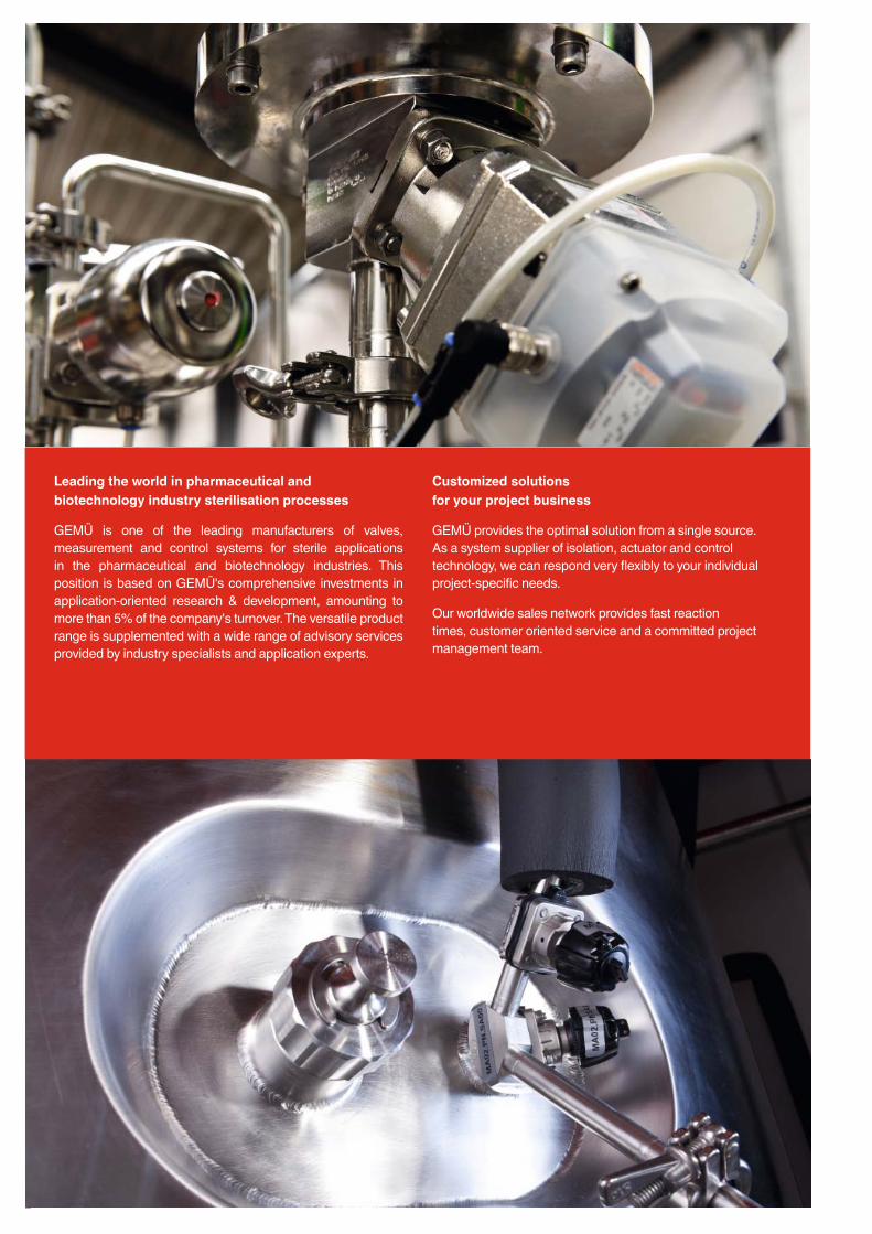
Leading the world in pharmaceutical and biotechnology industry sterilisation processes
GEMÜ is one of the leading manufacturers of valves, measurement and control systems for sterile applications in the pharmaceutical and biotechnology industries. This position is based on GEMÜ's comprehensive investments in application-oriented research & development, amounting to more than 5% of the company's turnover. The versatile product range is supplemented with a wide range of advisory services provided by industry specialists and application experts.
Customized solutions for your project business
GEMÜ provides the optimal solution from a single source.As a system supplier of isolation, actuator and control technology, we can respond very fl exibly to your individual project-specifi c needs.
Our worldwide sales network provides fast reaction times, customer oriented service and a committed project management team.
www.gemu-group.com 3
Description of use 4
B600 Tank valves, Overview of applications 5
B600 Tank valves, Standard version 6
Simple draining/tank bottom valve 7
CIP/SIP of the tank outletExamples with welded on diaphragm valve 8
CIP/SIP of the tank outlet Examples with integrated diaphragm valve 9
CIP/SIP of the tank Examples with welded on diaphragm valve 10
CIP/SIP of the tank Examples with integrated diaphragm valve 11
Tank bottom/venting valve with vertical outlet spigot 12
Venting valveExamples with welded on diaphragm valve 13
Tank outlet as ring mainwith two outlet spigots 14
Sterile sampling from a tank 15 - 16
Sterile sampling Example with integrated diaphragm valve 17
Sterile sampling from a tank 18 - 19
Sterile sampling Examples with welded on diaphragm valve 20
Sterile take-off /samplingFixing via clamp connection 21
Tank bottom valve body with detachable connection 22
Tank bottom with integrated agitator connection 23
Special applications 24
Installation examples 25
Butt weld connections / Grades of surface fi nish 26
Butt weld connections 27 - 28
Clamp bodies 29
Materials and certifi cates 30
Certifi cates and approvals 31
GEMÜ diaphragms 32 - 35
Selection of operators 36 - 38
Positioners and process controllers 39
Combi switchboxes and electrical position indicators 40
Specifi cation of tank valves 41 - 42
GEMÜ manufacturing sites and sales locations worldwide 43
Table of contents

4
Description of use
Today tank valves are available in a large number of versions. They can be installed or welded into the tank cover, tank wall or tank bottom. Their main functions are for fi lling, sampling and draining the tank contents. Sometimes these functions are combined in one valve for reasons of process safety and sometimes even extra functions are added such as integrated CIP/SIP connections.
All these GEMÜ valves have one thing in common. They are diaphragm valves whose sealing weir is as close as possible to the tank wall to avoid deadlegs in the tank. The internal of the tank bottom valve body has a specially designed cavity which promotes optimum draining of the tank contents and improves their cleanability and sterilisation. Only this cavity ensures optimised draining of the tank.
Features• Being very compact, the tank valves are ideal for applications
where space is at a premium
• Minimal deadlegs and optimized draining capabilities
• The valve body is machined from a single piece of block material (monoblock – no welded components)
• CIP/SIP capable and sterilisable
• The internal surface contour of the valve body is available mechanically and/or electropolished down to Ra 0.25 μm
• Optimised fl ow geometry
• Pipe connections such as butt weld spigots, clamps and threaded connections are available in accordance with industrial standards
• Valve body materials are 1.4435/316L, other alloys are available to customer specifi cation or test requirements
• Welding into the tank bottom is simplifi ed by a welding neck (standard 6 mm)
• Available with manual, pneumatic or motorized operatorsfrom the GEMÜ modular system
• Optical and/or electrical position indicators are available as actuator instrumentation

www.gemu-group.com 5
CIP/SIP of the tank outletTank bottom valve with welded on or integrated diaphragm valve. The welded on diaphragm valve is turned for optimized draining, if technically possible.
For design examples see pages 8-9.
CIP/SIP of the tank or direct sampling from the tankTank bottom valve with welded on or integrated diaphragm valve. The welded on diaphragm valve is turned for optimized draining, if technically possible.
For design examples see pages 10-11.
Venting valveTank valve with vertical outlet spigot.Available with additional welded on or integrated diaphragm valve depending on the version. The welded on diaphragm valve is turned for optimized draining, if technically possible.
For design examples see pages 12-13.
Tank outlet as ring mainTank bottom valve with two outlet spigots for simple integration into a ring main.
For design examples see page 14.
Sterile samplingTank valve with intergrated sampling option. Also available with integrated CIP/SIP function.
For design examples see pages 15-21.
B600 tank valves Overview of applications
6
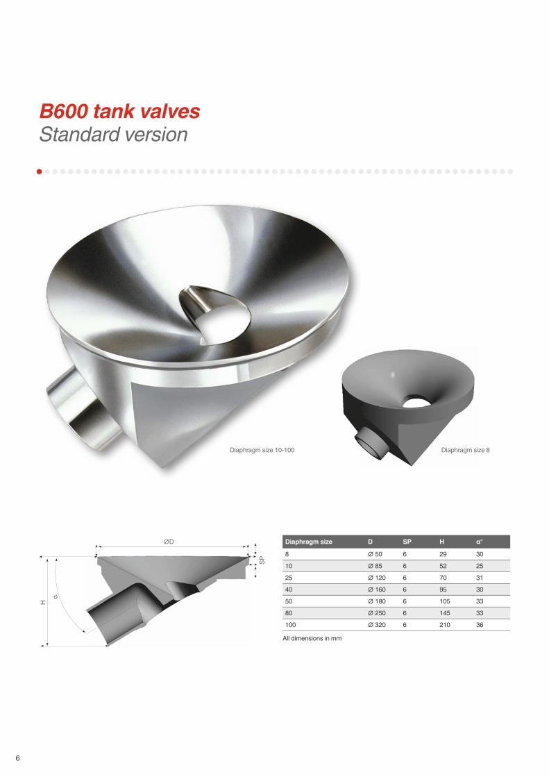
B600 tank valvesStandard version
Diaphragm size D SP H α°
8 ∅ 50 6 29 30
10 ∅ 85 6 52 25
25 ∅ 120 6 70 31
40 ∅ 160 6 95 30
50 ∅ 180 6 105 33
80 ∅ 250 6 145 33
100 ∅ 320 6 210 36
All dimensions in mm
Diaphragm size 10-100 Diaphragm size 8
SP
∅D
α
H
www.gemu-group.com 7
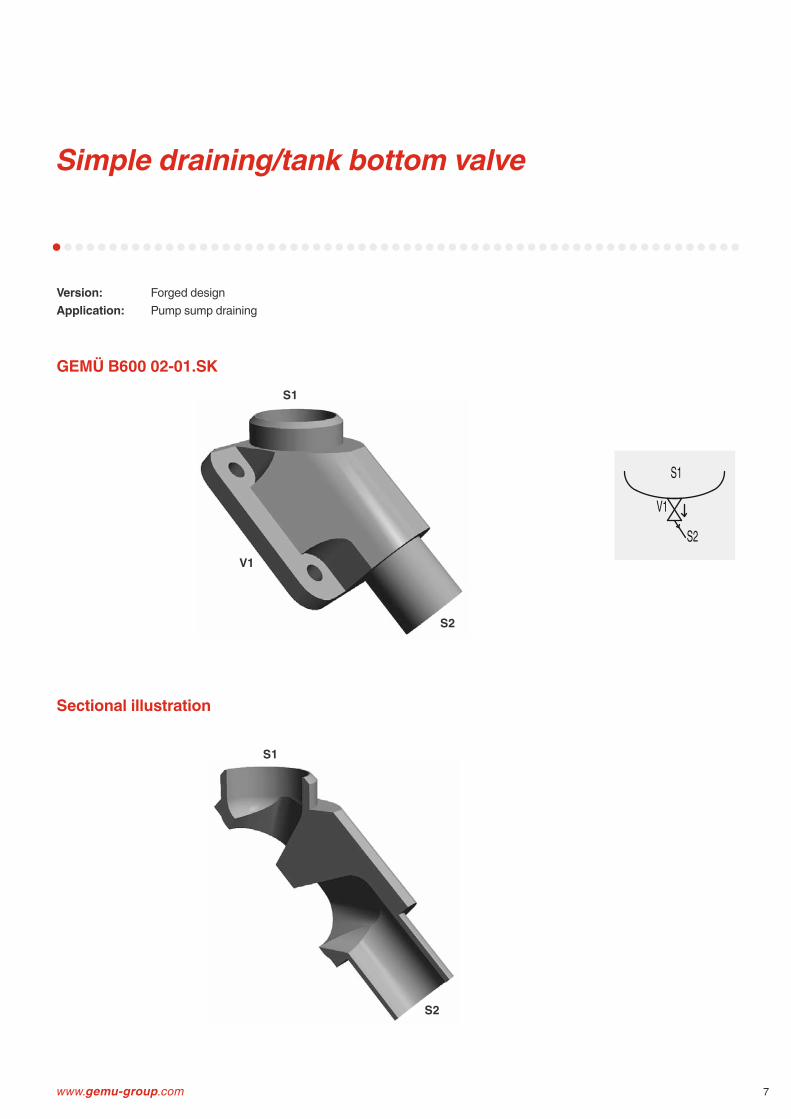
Simple draining/tank bottom valve
Version: Forged designApplication: Pump sump draining
S1
S2
S2
S1
V1
S1
S2
V1
GEMÜ B600 02-01.SK
Sectional illustration

8
CIP/SIP of the tank outletExamples with welded on diaphragm valve
Application: CIP/SIP of the tank outletInstallation: Tank bottom
S1
S2S3
S1
S2 S3
S1
S2S3
S1
S2S3
S1
S1
S2
S2
S3
S3
S1
S1
S2
S2
S3
S3
V1 V2
V1
V2
V1
V2
V1
V2
GEMÜ B600 03-02.A: Diaphragm valve right, orientation to front
GEMÜ B600 03-02.B: Diaphragm valve left, orientation to front
GEMÜ B600 03-02.C: Diaphragm valve right, orientation to back
GEMÜ B600 03-02.D: Diaphragm valve left, orientation to back
S1
V1 V2S3/ H
S2
S1
V1V2S3/ H
S2
S1
V1V2S3/ H
S2
S1
V1 V2S3/ H
S2
www.gemu-group.com 9
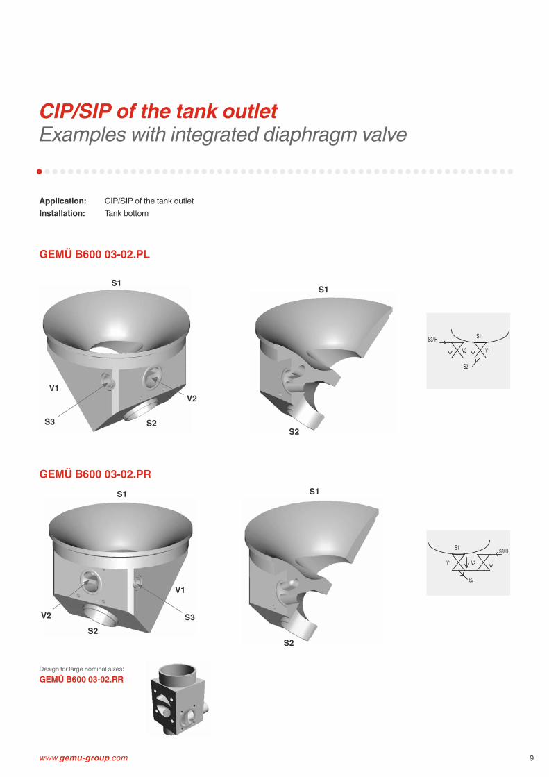
CIP/SIP of the tank outletExamples with integrated diaphragm valve
Application: CIP/SIP of the tank outletInstallation: Tank bottom
S2
S1
V1V2S3/ H
S2
S1
V1 V2
S3/ H
S1
S2
S1
S2
GEMÜ B600 03-02.PL
Design for large nominal sizes:GEMÜ B600 03-02.RR
GEMÜ B600 03-02.PR
S1
S2S3
V1V2
S1
S2S3
V1
V2

10
CIP/SIP of the tank Examples with welded on diaphragm valve
Application: CIP/SIP of the tank or direct sampling from the tankInstallation: Tank bottom
S1
S2S3
S1
S2S3
S1
S2S3
S1
S2S3
S1
S2S3
S1
S2S3
S1
S2S3
S1
S2S3
V1
V2
V1
V2
V1
V2
V1
V2
GEMÜ B600 03-02.K: Diaphragm valve right, orientation to front
GEMÜ B600 03-02.L: Diaphragm valve left, orientation to front
GEMÜ B600 03-02.M: Diaphragm valve right, orientation to back
GEMÜ B600 03-02.N: Diaphragm valve left, orientation to back
S2
S3/ HS1
V1
V2
S2
S3/ HS1
V1
V2
S2
S3/ H S1
V1
V2
S2
S3/ H S1
V1
V2
www.gemu-group.com 11
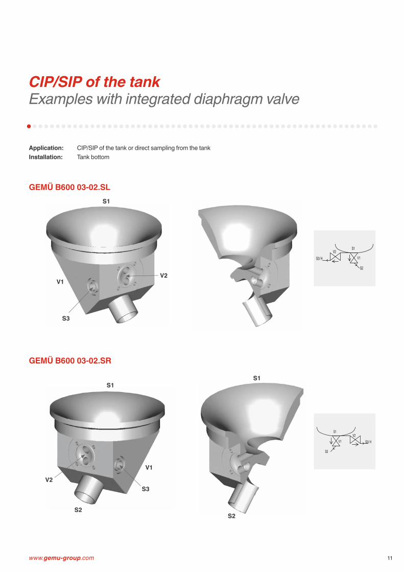
CIP/SIP of the tank Examples with integrated diaphragm valve
Application: CIP/SIP of the tank or direct sampling from the tankInstallation: Tank bottom
S1
S2
S1
S2
S3
S1
S3
V1V2
V1
V2
GEMÜ B600 03-02.SL
GEMÜ B600 03-02.SR
S2
S3/ H
S1
V1V2
S2
S3/ H
S1
V1V2

12
Tank bottom outlet/venting valve with vertical outlet spigot
Application: Outlet valve at the bottom or venting valve in the tank coverInstallation: Tank bottom, tank cover
S1
S2
V1
S1
S2
V1
Alternative installation position:
GEMÜ B600 02-01.H
Sectional illustration
S2/ V
S1V1
www.gemu-group.com 13
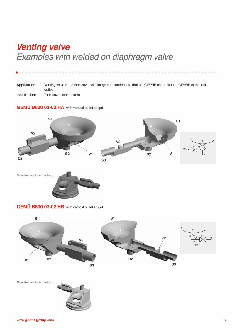
Venting valveExamples with welded on diaphragm valve
Application: Venting valve in the tank cover with integrated condensate drain or CIP/SIP connection or CIP/SIP of the tank outlet
Installation: Tank cover, tank bottom
GEMÜ B600 03-02.HA: with vertical outlet spigot
GEMÜ B600 03-02.HB: with vertical outlet spigot
S1
S2 V1
S1
S2 V1S3 S3
V2
V2
Alternative installation position:
S1
S2V1
S1
S2S3 S3
V2
Alternative installation position:
V2
S1
V1V2S3/ H
S2/ V
S1
V1 V2S3/ H
S2/ V

14
Tank outlet as ring mainwith two outlet spigots
Application: Tank outlet which can be integrated into ring mainInstallation: Tank bottom
GEMÜ B600 03-01.V: Can be integrated into ring main
GEMÜ B600 03-01.Y: Ring main directly under the tank
S1
S2
S3
S1
S2
S3
S1
S2S3
S1
S2
S3
V1
V1
S3/H
S1
V1
S2/H
S1
V1
S2 S3
www.gemu-group.com 15
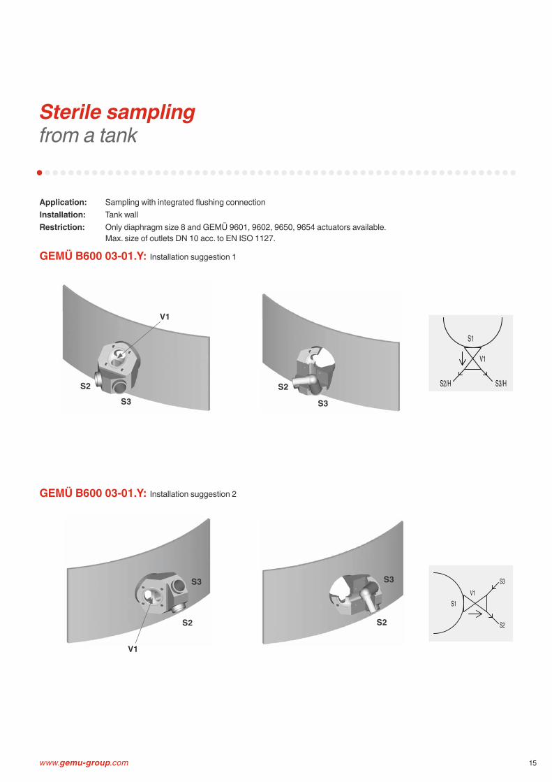
Sterile sampling from a tank
Application: Sampling with integrated fl ushing connectionInstallation: Tank wallRestriction: Only diaphragm size 8 and GEMÜ 9601, 9602, 9650, 9654 actuators available.
Max. size of outlets DN 10 acc. to EN ISO 1127.
GEMÜ B600 03-01.Y: Installation suggestion 1
GEMÜ B600 03-01.Y: Installation suggestion 2
S3
S2 S2
S3
V1
S3
S2
S3
S2
V1
S1V1
S2
S3
S1
V1
S2/H S3/H

16
Sterile sampling from a tank
Application: Sampling with integrated fl ushing connectionInstallation: Tank bottomRestriction: Only diaphragm size 8 and GEMÜ 9601, 9602, 9650, 9654 actuators available.
Max. size of outlets DN 10 acc. to EN ISO 1127.
GEMÜ B600 03-01.Y1: Flushing connection on the right
GEMÜ B600 03-01.Y2: Flushing connection on the left
S1
S2S3
S1
S2S3
S1
S2S3
S1
S2S3
V1
V1
S2S3/ H
S1V1
S2S3/ H
S1
V1
www.gemu-group.com 17
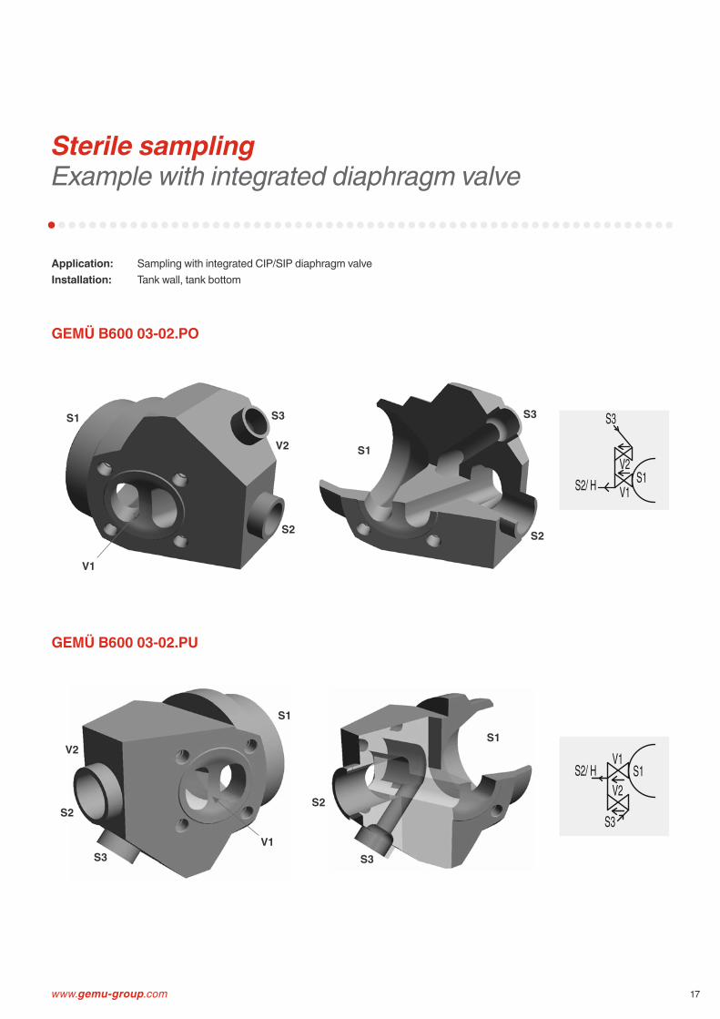
Sterile sampling Example with integrated diaphragm valve
Application: Sampling with integrated CIP/SIP diaphragm valveInstallation: Tank wall, tank bottom
GEMÜ B600 03-02.PO
GEMÜ B600 03-02.PU
S1
S2
S1
S2
V1
S1
S2
S1
S2
S3 S3
S3V1
S3
V2
V2
S1V1S2/ HV2
S3
S1V1
S2/ HV2
S3
18
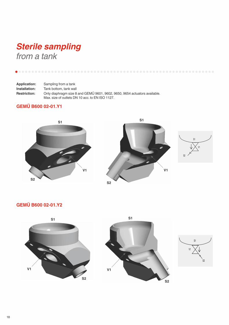
Sterile sampling from a tank
Application: Sampling from a tankInstallation: Tank bottom, tank wallRestriction: Only diaphragm size 8 and GEMÜ 9601, 9602, 9650, 9654 actuators available.
Max. size of outlets DN 10 acc. to EN ISO 1127.
GEMÜ B600 02-01.Y1
GEMÜ B600 02-01.Y2
S2
S1
V1
S2
S1
V1
S1
S2
S1
S2
V1
S1
S2
S1
S2
V1
V1 V1

www.gemu-group.com 19
Sterile sampling from a tank
Application: Sampling from a tankInstallation: Tank wall
GEMÜ B600 02-01.F
Sectional illustration
S1V1
S2
S2
S1
S2
V1
20
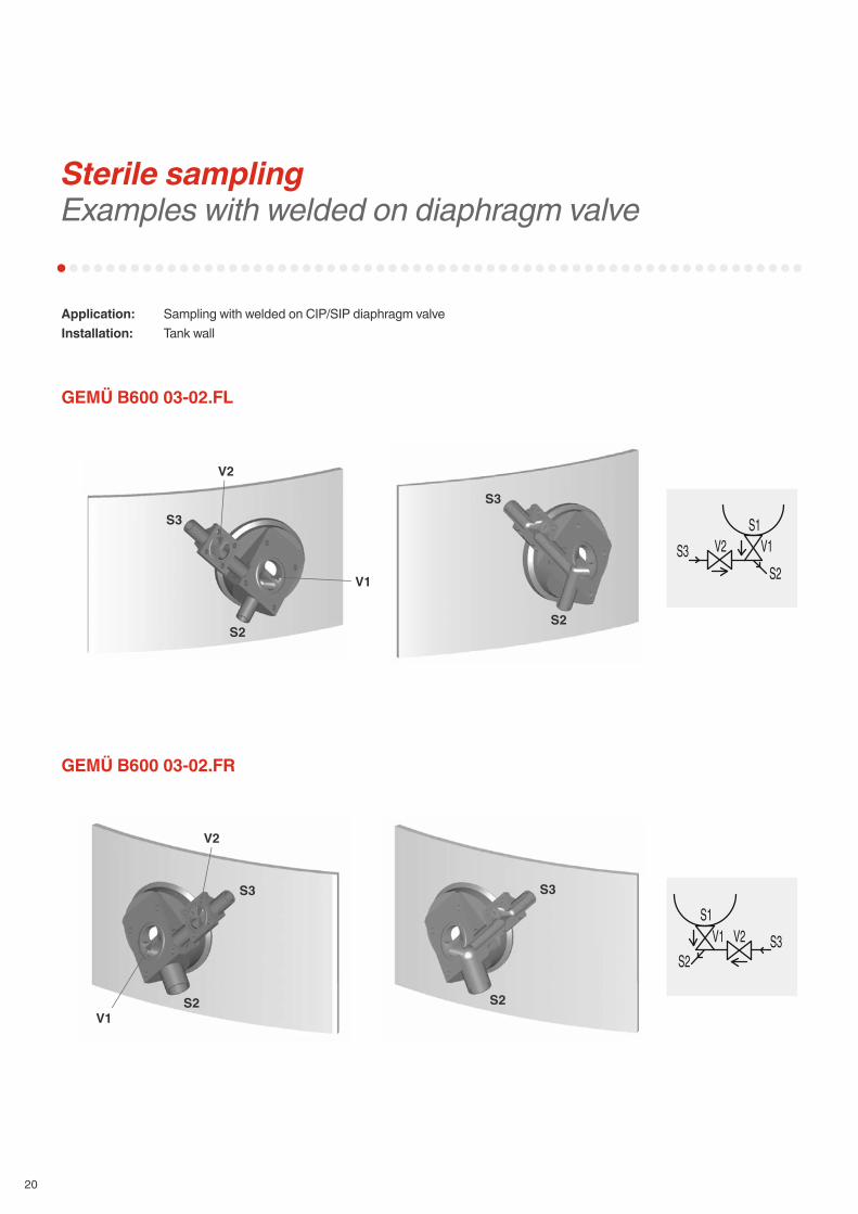
Sterile sampling Examples with welded on diaphragm valve
Application: Sampling with welded on CIP/SIP diaphragm valveInstallation: Tank wall
GEMÜ B600 03-02.FL
GEMÜ B600 03-02.FR
S2
S3
S2
S3
S2
S3
S2
S3
V2
V1
V2
V1
S3 V2S2
V1S1
S1V1
S2V2 S3

www.gemu-group.com 21
Sterile take-off /samplingFixing via clamp connection
Application: Sterile take-off /sampling with integrated clamp connectionInstallation: Tank bottom, tank wallRestriction: Only diaphragm size 8 and GEMÜ 9601, 9602, 9650, 9654 actuators available.
Max. size of outlets DN 10 acc. to EN ISO 1127.
GEMÜ B600 02-01.Y3
GEMÜ B600 03-01.Y3
S1
S2
V1
S1
S2
V1
S1
S2
V1 V1
S1
S2
S3 S3
Alternative installation positions:
Alternative installation positions:
S2
S1
V1
S2
S1
V1
S3

22
Tank bottom valve body with detachable connection
Application: Sterile take-off /sampling with integrated fl anged connectionInstallation: Tank bottom
GEMÜ B600 02-01.B
Sectional illustration
S1
S2
S1
S2
V1
S2
S1
V1

www.gemu-group.com 23
Tank bottom with integrated agitator connection
Application: Tank bottom outlet with integrated agitator connection (B600 02-01.TB) or tank bottom outlet with integrated agitator and fl ushing connection (B600 03-02.TB)
Installation: Tank bottom
GEMÜ B600 02-01.TB
GEMÜ B600 03-02.TB
S2 S2V1 V1
S1 S1
S1 S1
S2 S2S3 S3
V1 V1V2 V2
S2/V
S1
V1
V1 V2S3/ H
S2/ V
S1
24
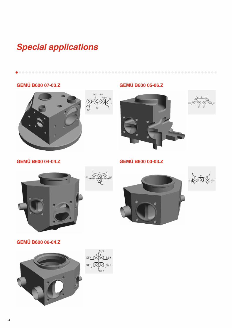
Special applications
GEMÜ B600 07-03.Z GEMÜ B600 05-06.Z
GEMÜ B600 04-04.Z GEMÜ B600 03-03.Z
GEMÜ B600 06-04.Z
S1V2
S2/ H
V1
V4V3 V5 V6 S5/ H
S3/ V S4/ VS1
V3
S2/ V
V1S3
V2
S6/ V S7/ V
S4S5/ V
S1
V1V4V3
S3/ H S4/ HV2
S2
S6/ H
S1/ V
S2/ V
S5/ H
S3/ H
S4/ H
S1
V1S2/ HV2 V3
S3/ H
www.gemu-group.com 25
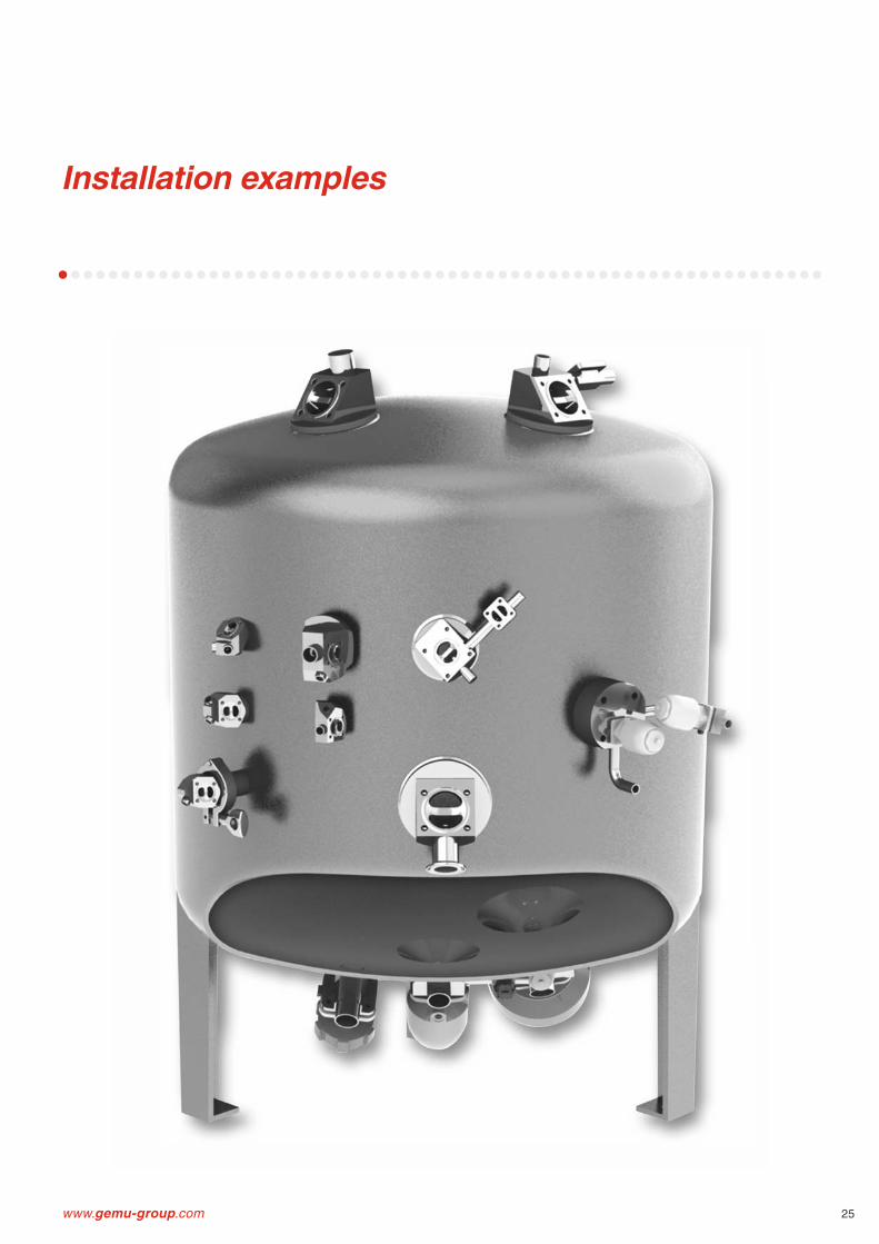
Installation examples

26
Butt weld connections / Surface fi nish
The diff erence between tube specifi cations (Example DN 15)
Modern, ergonomically shaped workstations and trained polishing staff give us the ability to provide high quality surface fi nishes. Depending on the required application, surface fi nishes from Ra 0.8 μm down to 0.25 μm can be achieved by polishing, electro polishing or a special process, we call “elysieren“.
Mechanical hand polishing is carried out at our works to ensure our high quality standard.In principle, special connections requested by customers can be provided on GEMÜ butt weld spigot bodies and it is also possible to have diff erent connections on one body.
Valve body surface fi nish, internal contourForged body - Codes 40, 42 Block material - Codes 41, 43
Investment castingCodes 32, 34 Code
Ra ≤ 0.8 μm, mechanically polished internal, blasted external X X 1502
Ra ≤ 0.8 μm, electropolished internal/external X - 1503
Ra ≤ 0.6 μm, mechanically polished internal, blasted external X X 1507
Ra ≤ 0.6 μm, electropolished internal/external X - 1508
Ra ≤ 0.4 μm, mechanically polished internal, blasted external X - 1536
Ra ≤ 0.4 μm, electropolished internal/external X - 1537
Ra ≤ 0.25 μm, mechanically polished internal, blasted external X - 1527
Ra ≤ 0.25 μm, electropolished internal/external X - 1516
Ra acc. to DIN 4768; at defi ned reference points. Surface fi nish data refers to media wetted surfaces.
ISO
ød = 21.3s = 1.6
JIS3459
ød = 21.7s = 2.1
DINSeries 0ød = 18s = 1.5
DINSeries 1ød = 18s = 1.0
DINSeries 2ød = 19s = 1.5
DINSeries 3ød = 20s = 2.0
BS-ODTubing
ød = 12.7s = 1.2
ASMEBPE
ød = 12.7s = 1.65
ø d
s

www.gemu-group.com 27
Butt weld connections
Continued on the next page
Dimensions in mm
DIN DIN 11850 DIN 11866 EN ISO 1127Series 0Code 0
Series 1Code 16
Series 2Code 17
Series 3Code 18
Series ACode 1A
Series BCode 1B
Code 60
MG DN NPS ød s ød s ød s ød s ød s ød s ød s
8
4 - 6 1.0 - - - - - - - - - - - -
6 - 8 1.0 - - - - - - 8 1.0 10.2 1.6 10.2 1.6
8 ¼" 10 1.0 - - - - - - 10 1.0 13.5 1.6 13.5 1.6
10 ⅜" - - 12 1.0 13 1.5 14 2.0 13 1.5 - - - -
15 ½" - - - - - - - - - - - - - -
10
10 ⅜" - - 12 1.0 13 1.5 14 2.0 13 1.5 17.2 1.6 17.2 1.6
15 ½" 18 1.5 18 1.0 19 1.5 20 2.0 19 1.5 21.3 1.6 21.3 1.6
20 ¾" - - - - - - - - - - - - - -
25
15 ½" 18 1.5 18 1.0 19 1.5 20 2.0 19 1.5 21.3 1.6 21.3 1.6
20 ¾" 22 1.5 22 1.0 23 1.5 24 2.0 23 1.5 26.9 1.6 26.9 1.6
25 1" 28 1.5 28 1.0 29 1.5 30 2.0 29 1.5 33.7 2.0 33.7 2.0
4032 1 ¼" 34 1.5 34 1.0 35 1.5 36 2.0 35 1.5 42.4 2.0 42.4 2.0
40 1 ½" 40 1.5 40 1.0 41 1.5 42 2.0 41 1.5 48.3 2.0 48.3 2.0
50 50 2" 52 1.5 52 1.0 53 1.5 54 2.0 53 1.5 60.3 2.0 60.3 2.0
8065 2 ½" - - - - 70 2.0 - - 70 2.0 76.1 2.0 76.1 2.0
80 3" - - - - 85 2.0 - - 85 2.0 88.9 2.3 88.9 2.3
100 100 4" - - - - 104 2.0 - - 104 2.0 114.3 2.3 114.3 2.3
MG = diaphragm size

28
Butt weld connections
Dimensions in mm
JIS-G3447Code 35
JIS-G3459Code 36
SMS3008Code 37
BS 4825Code 55
ASMEBPECode 59
ANSI/ASMEB36.19M 10s Code 63
ANSI/ASMEB36.19M 40s Code 65
MG DN NPS ød s ød s ød s ød s ød s ød s ød s
8
4 - - - - - - - - - - - - - - -6 - - - 10.5 1.20 - - - - - - 10.3 1.24 10.3 1.738 ¼" - - 13.8 1.65 - - 6.35 1.2 6.35 0.89 13.7 1.65 13.7 2.2410 ⅜" - - - - - - 9.53 1.2 9.53 0.89 - - - -15 ½" - - - - - - 12.70 1.2 12.70 1.65 - - - -
1010 ⅜" - - 17.3 1.65 - - 9.53 1.2 9.53 0.89 17.1 1.65 17.1 2.3115 ½" - - 21.7 2.10 - - 12.70 1.2 12.70 1.65 21.3 2.11 21.3 2.7720 ¾" - - - - - - 19.05 1.2 19.05 1.65 - - - -
2515 ½" - - 21.7 2.10 - - - - - - 21.3 2.11 21.3 2.7720 ¾" - - 27.2 2.10 - - 19.05 1.2 19.05 1.65 26.7 2.11 26.7 2.8725 1" 25.4 1.2 34.0 2.80 25.0 1.2 - - 25.40 1.65 33.4 2.77 33.4 3.38
4032 1 ¼" 31.8 1.2 42.7 2.80 33.7 1.2 - - - - 42.2 2.77 42.2 3.5640 1 ½" 38.1 1.2 48.6 2.80 38.0 1.2 - - 38.10 1.65 48.3 2.77 48.3 3.68
50 50 2" 50.8 1.5 60.5 2.80 51.0 1.2 - - 50.80 1.65 60.3 2.77 60.3 3.91
8065 2 ½" 63.5 2.0 76.3 3.00 63.5 1.6 - - 63.50 1.65 73.0 3.05 73.0 5.1680 3" 76.3 2.0 89.1 3.00 76.1 1.6 - - 76.20 1.65 88.9 3.05 88.9 5.49
100 100 4" 101.6 2.0 114.3 3.00 101.6 2.0 - - 101.60 2.11 114.3 3.05 114.3 6.02
MG = diaphragm size
www.gemu-group.com 29
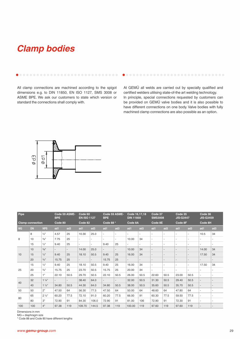
Clamp bodies
All clamp connections are machined according to the spigot dimensions e.g. to DIN 11850, EN ISO 1127, SMS 3008 or ASME BPE. We ask our customers to state which version or standard the connections shall comply with.
At GEMÜ all welds are carried out by specially qualifi ed and certifi ed welders utilising state-of-the art welding technology.In principle, special connections requested by customers can be provided on GEMÜ valve bodies and it is also possible to have diff erent connections on one body. Valve bodies with fully machined clamp connections are also possible as an option.
Pipe Code 59 ASME-BPE
Code 60 EN ISO 1127
Code 59 ASME-BPE
Code 16,17,18 DIN 11850
Code 37 SMS3008
Code 35JIS-G3447
Code 36JIS-G3459
Clamp connection Code 80 Code 82 Code 88 * Code 8A Code 8E Code 8F Code 8H
MG DN NPS ød1 ød3 ød1 ød3 ød1 ød3 ød1 ød3 ød1 ød3 ød1 ød3 ød1 ød3
8
8 ¼" 4.57 25 10.30 25.0 - - - - - - - - 10.5 34
10 ⅜" 7.75 25 - - - - 10.00 34 - - - - - -
15 ½" 9.40 25 - - 9.40 25 - - - - - - - -
10
10 ⅜" - - 14.00 25.0 - - 10.00 34 - - - - 14.00 34
15 ½" 9.40 25 18.10 50.5 9.40 25 16.00 34 - - - - 17.50 34
20 ¾" 15.75 25 - - 15.75 25 - - - - - - - -
25
15 ½" 9.40 25 18.10 50.5 9.40 25 16.00 34 - - - - 17.50 34
20 ¾" 15.75 25 23.70 50.5 15.75 25 20.00 34 - - - - - -
25 1" 22.10 50.5 29.70 50.5 22.10 50.5 26.00 50.5 22.60 50.5 23.00 50.5 - -
4032 1 ¼" - - 38.40 64.0 - - 32.00 50.5 31.30 50.5 29.40 50.5 - -
40 1 ½" 34.80 50.5 44.30 64.0 34.80 50.5 38.00 50.5 35.60 50.5 35.70 50.5 - -
50 50 2" 47.50 64 56.30 77.5 47.50 64 50.00 64 48.60 64 47.80 64 - -
8065 2 ½" 60.20 77.5 72.10 91.0 60.20 77.5 66.00 91 60.30 77.5 59.50 77.5 - -
80 3" 72.90 91 84.30 106.0 72.90 91 81.00 106 72.90 91 72.30 91 - -
100 100 4" 97.38 119 109.70 144.5 97.38 119 100.00 119 97.60 119 97.60 119 - -
Dimensions in mmMG = diaphragm size* Code 88 and Code 80 have diff erent lengths
30
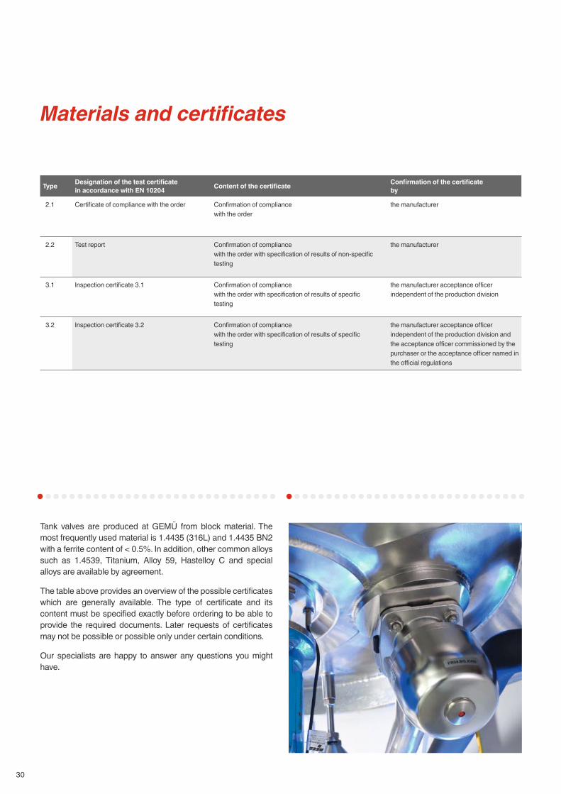
Materials and certifi cates
Tank valves are produced at GEMÜ from block material. The most frequently used material is 1.4435 (316L) and 1.4435 BN2 with a ferrite content of < 0.5%. In addition, other common alloys such as 1.4539, Titanium, Alloy 59, Hastelloy C and special alloys are available by agreement.
The table above provides an overview of the possible certifi cates which are generally available. The type of certifi cate and its content must be specifi ed exactly before ordering to be able to provide the required documents. Later requests of certifi cates may not be possible or possible only under certain conditions.
Our specialists are happy to answer any questions you might have.
Type Designation of the test certifi cate in accordance with EN 10204 Content of the certifi cate Confi rmation of the certifi cate
by
2.1 Certifi cate of compliance with the order Confi rmation of compliance with the order
the manufacturer
2.2 Test report Confi rmation of compliance with the order with specifi cation of results of non-specifi c testing
the manufacturer
3.1 Inspection certifi cate 3.1 Confi rmation of compliance with the order with specifi cation of results of specifi c testing
the manufacturer acceptance offi cer independent of the production division
3.2 Inspection certifi cate 3.2 Confi rmation of compliance with the order with specifi cation of results of specifi c testing
the manufacturer acceptance offi cer independent of the production division and the acceptance offi cer commissioned by the purchaser or the acceptance offi cer named in the offi cial regulations
www.gemu-group.com 31
There is no universal diaphragm for all applications, hence we use diff erent rubber mixtures and materials for our diaphragms. The diff erent diaphragms have been certifi ed according to their main fi elds of application so that we can certify conformity with the international regulations and rules below.
FDA (U.S. Food and Drug Administration)FDA Extraction according to 21CFR 177.2600 for elastomers and 21CFR 177.1550 for PTFE.
USP (United States Pharmacopeia)An independent institution has tested our diaphragms according to the regulations of the USP Class VI Chapter 87 In-Vitro and Chapter 88 In-Vivo. Furthermore, our diaphragms are free from animal ingredients.
EHEDGHygiene standards in the foodstuff and beverage industry are continuously increasing and are approaching those of the pharmaceutical industry in sensitive areas. For this reason, the EHEDG was established some years ago (European Hygienic Engineering and Design Group). GEMÜ was the fi rst diaphragm valve manufacturer worldwide to be granted certifi cation for its diaphragm valve system developed in 1999. The examination took place in 2002.
RoHSGEMÜ diaphragms comply with the RoHS Directive 2011/65 EC and the WEEE Directive 2002/96 EC.
Pressure Equipment DirectiveAs all diaphragm valves are pressure bearing components and as the diaphragm is the central sealing element in addition to the valve body, all diaphragms also comply with the European Pressure Equipment Directive 97/23EC Art. 3 § 3. If no original GEMÜ shut-off diaphragms are installed, GEMÜ cannot accept any responsibility.
GOST certifi cateGEMÜ diaphragm valves are certifi ed to the Russian GOST and meet the hygienic requirements of the foodstuff industry in Russia.
Certifi cates and approvals
32
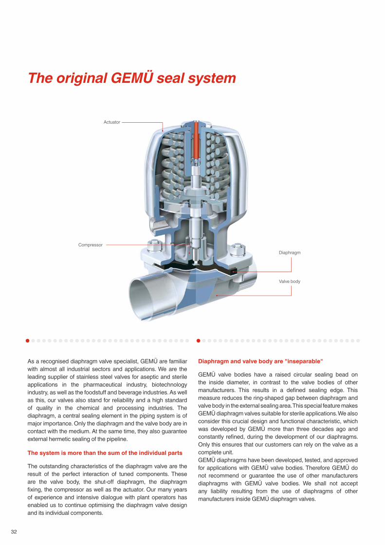
The original GEMÜ seal system
As a recognised diaphragm valve specialist, GEMÜ are familiar with almost all industrial sectors and applications. We are the leading supplier of stainless steel valves for aseptic and sterile applications in the pharmaceutical industry, biotechnology industry, as well as the foodstuff and beverage industries. As well as this, our valves also stand for reliability and a high standard of quality in the chemical and processing industries. The diaphragm, a central sealing element in the piping system is of major importance. Only the diaphragm and the valve body are in contact with the medium. At the same time, they also guarantee external hermetic sealing of the pipeline.
The system is more than the sum of the individual parts
The outstanding characteristics of the diaphragm valve are the result of the perfect interaction of tuned components. These are the valve body, the shut-off diaphragm, the diaphragm fi xing, the compressor as well as the actuator. Our many years of experience and intensive dialogue with plant operators has enabled us to continue optimising the diaphragm valve design and its individual components.
Diaphragm and valve body are "inseparable"
GEMÜ valve bodies have a raised circular sealing bead on the inside diameter, in contrast to the valve bodies of other manufacturers. This results in a defi ned sealing edge. This measure reduces the ring-shaped gap between diaphragm and valve body in the external sealing area. This special feature makes GEMÜ diaphragm valves suitable for sterile applications. We also consider this crucial design and functional characteristic, which was developed by GEMÜ more than three decades ago and constantly refi ned, during the development of our diaphragms. Only this ensures that our customers can rely on the valve as a complete unit. GEMÜ diaphragms have been developed, tested, and approved for applications with GEMÜ valve bodies. Therefore GEMÜ do not recommend or guarantee the use of other manufacturers diaphragms with GEMÜ valve bodies. We shall not accept any liability resulting from the use of diaphragms of other manufacturers inside GEMÜ diaphragm valves.
Actuator
DiaphragmCompressor
Valve body

www.gemu-group.com 33
Flexible diaphragm fi xing
The diaphragm is uniformly fi xed in the compressor by means of a threaded pin. The only exception is the smallest diaphragm size (diaphragm size 8), which is pushed in with a rubber pin. The uniform fi xing method applies both to soft elastomer and PTFE diaphragms. The largest advantage of fi xing by means of a threaded pin, e.g. in comparison to a bayonet fi tting, is the even transfer of forces onto the large area of the fl anks of the screw thread. This prevents damage to the mechanical connection between compressor and diaphragm especially under vacuum operating conditions. The uniform fi xing of elastomer and PTFE diaphragms enables subsequent replacement of the diaphragm while using the same actuator.
Diaphragm sizes 10 - 100
Diaphragm size 8
GEMÜ seal system Conventional seal systems
As a leading manufacturer world-wide we had the GEMÜ diaphragm seal system certifi ed in 2002 and were granted the EHEDG certifi cate.
Seal system
34
Diaphragm Material/Design Diaphragm size
Temperature range [°C]
CodeLiquid media Sterilisation ¹
Min. Max.
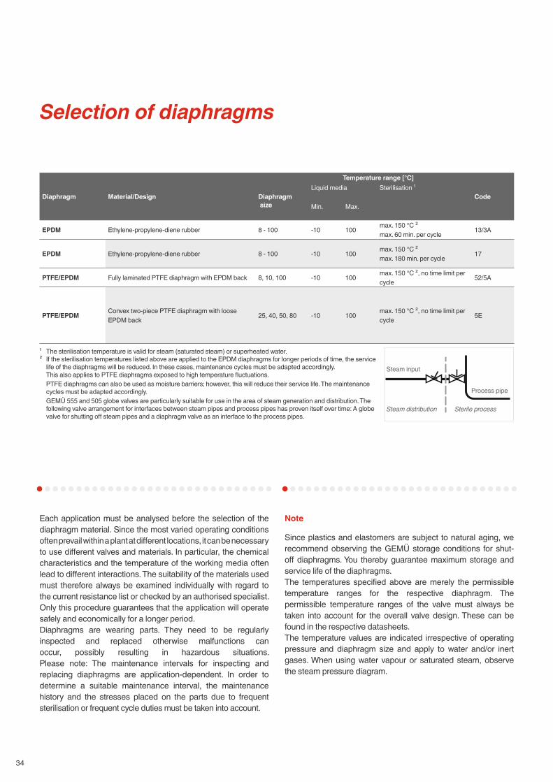
EPDM Ethylene-propylene-diene rubber 8 - 100 -10 100 max. 150 °C ²max. 60 min. per cycle 13/3A
EPDM Ethylene-propylene-diene rubber 8 - 100 -10 100 max. 150 °C ²max. 180 min. per cycle 17
PTFE/EPDM Fully laminated PTFE diaphragm with EPDM back 8, 10, 100 -10 100 max. 150 °C ², no time limit per cycle 52/5A
PTFE/EPDM Convex two-piece PTFE diaphragm with loose EPDM back 25, 40, 50, 80 -10 100 max. 150 °C ², no time limit per
cycle 5E
¹ The sterilisation temperature is valid for steam (saturated steam) or superheated water.² If the sterilisation temperatures listed above are applied to the EPDM diaphragms for longer periods of time, the service
life of the diaphragms will be reduced. In these cases, maintenance cycles must be adapted accordingly. This also applies to PTFE diaphragms exposed to high temperature fl uctuations.PTFE diaphragms can also be used as moisture barriers; however, this will reduce their service life. The maintenance cycles must be adapted accordingly.GEMÜ 555 and 505 globe valves are particularly suitable for use in the area of steam generation and distribution. The following valve arrangement for interfaces between steam pipes and process pipes has proven itself over time: A globe valve for shutting off steam pipes and a diaphragm valve as an interface to the process pipes.
Selection of diaphragms
Each application must be analysed before the selection of the diaphragm material. Since the most varied operating conditions often prevail within a plant at diff erent locations, it can be necessary to use diff erent valves and materials. In particular, the chemical characteristics and the temperature of the working media often lead to diff erent interactions. The suitability of the materials used must therefore always be examined individually with regard to the current resistance list or checked by an authorised specialist. Only this procedure guarantees that the application will operate safely and economically for a longer period.Diaphragms are wearing parts. They need to be regularly inspected and replaced otherwise malfunctions can occur, possibly resulting in hazardous situations. Please note: The maintenance intervals for inspecting and replacing diaphragms are application-dependent. In order to determine a suitable maintenance interval, the maintenance history and the stresses placed on the parts due to frequent sterilisation or frequent cycle duties must be taken into account.
Note
Since plastics and elastomers are subject to natural aging, we recommend observing the GEMÜ storage conditions for shut-off diaphragms. You thereby guarantee maximum storage and service life of the diaphragms.The temperatures specifi ed above are merely the permissible temperature ranges for the respective diaphragm. The permissible temperature ranges of the valve must always be taken into account for the overall valve design. These can be found in the respective datasheets.The temperature values are indicated irrespective of operating pressure and diaphragm size and apply to water and/or inert gases. When using water vapour or saturated steam, observe the steam pressure diagram.
Steam input
Steam distribution Sterile process
Process pipe

www.gemu-group.com 35
Certifi cates and approvals
Compatibility with media Special featuresFDA compliant
USP Class VI
EHEDG TA Luft (German Clean Air Act)
O₂ BAM
● ● ● ● ● Very good all-round elastomer, resistant to many acidic and alkaline media, demineralised and deionised hot water, inert and many other industrial gases.
Suitable for vacuum, low gas permeability, applicable for steam sterilisation.
● ● ● ●Compound and construction of the diaphragm have been specially optimised for steam applications, clearly improved service life.
● ● ● ●Resistant to nearly all chemicals, such as strong acids, alkalis and salts, also at high temperatures, steam, WFI as well as pharmaceuticals. Good resistance to solvents, chlorine, and aromatic hydrocarbons.
Fully laminated diaphragm, can be used in steam. Low gas permeability.
● ● ● ● ●
Convex two-piece diaphragm with loose PTFE face for higher switching cycles, can be used for permanent steam application. Special compounding and production by GEMÜ. Special seal contour for external sealing on the bottom of the diaphragm. Low gas permeability.
EPDM diaphragm dimensions [mm]
MG* DN NPS A B C D ød e h W α β γ Y Number ofbolt holes
8 4 - 15 ¼" -½" 22 22 31.5 31.5 4.5 4 5.6 - - - - - 410 10 - 20 ⅜" - ¾" 39 44 48 53 5.2 5 9 M4 - - - - 425 15 - 25 ½" - 1" 54 46 71.7 66.7 9 6 8 ¼" - - - - 440 32 - 40 1¼" - 1½" 70 65 100 90 11.5 7 8 ¼" - - - - 450 50 2" 82 78 124 106 13 7 7 ¼" - - - - 480 80 3" 127 114 186 156 18 9 8 5⁄16" - - - - 4100 100 4" 194 - 228 - 13 10 9 5⁄16" 28° 42° 40° - 8
* Diaphragm sizeThe thread of the diaphragm pin "W" corresponds to Whitworth standard.
K
K
e
d
ød
W
h
e
(Z holes)
Diaphragm size 8 Diaphragm size 8 - 80

Manually operated
Type 9601 9602 9612 9673 9653 9654
Features
Stainless steel, plastic handwheel, with optical position indicator and seal adjuster
Stainless steel, with optical position indicator and seal adjuster
Stainless steel, plastic handwheel, with optical position indicator and seal adjuster
Stainless steel, plastic handwheel, with optical position indicator and seal adjuster
Stainless steel, plastic handwheel, with optical position indicator, stroke limiter/seal adjuster, lockable, optional: electrical position indicator
Stainless steel, with optical position indicator, stroke limiter/seal adjuster, lockable, optional: electrical position indicator
Autoclavable ● ● ● ● ● ●Operating temperature* -10 to 150 °C -10 to 150 °C -10 to 150 °C -10 to 150 °C -10 to 150 °C -10 to 150 °C
Operating pressure* 0 to 10 bar 0 to 10 bar 0 to 10 bar 0 to 10 bar 0 to 10 bar 0 to 10 bar
DN 4 - 15 4 - 15 10 - 20 15 - 50 10 - 100 4 - 100
Diaphragm size 8 ● ● - - - ●Diaphragm size 10 - - ● - ● ●Diaphragm size 25 - - - ● ● ●Diaphragm size 40 - - - ● ● ●Diaphragm size 50 - - - ● ● ●Diaphragm size 80 - - - - ● ●Diaphragm size 100 - - - - ● ●
* max. media temperature, dependent on diaphragm material** dependent on diaphragm material
Elastomer diaphragmsEPDM
PTFE diaphragmsPTFE/EPDM, PTFE/FPM
36
Selection of operators
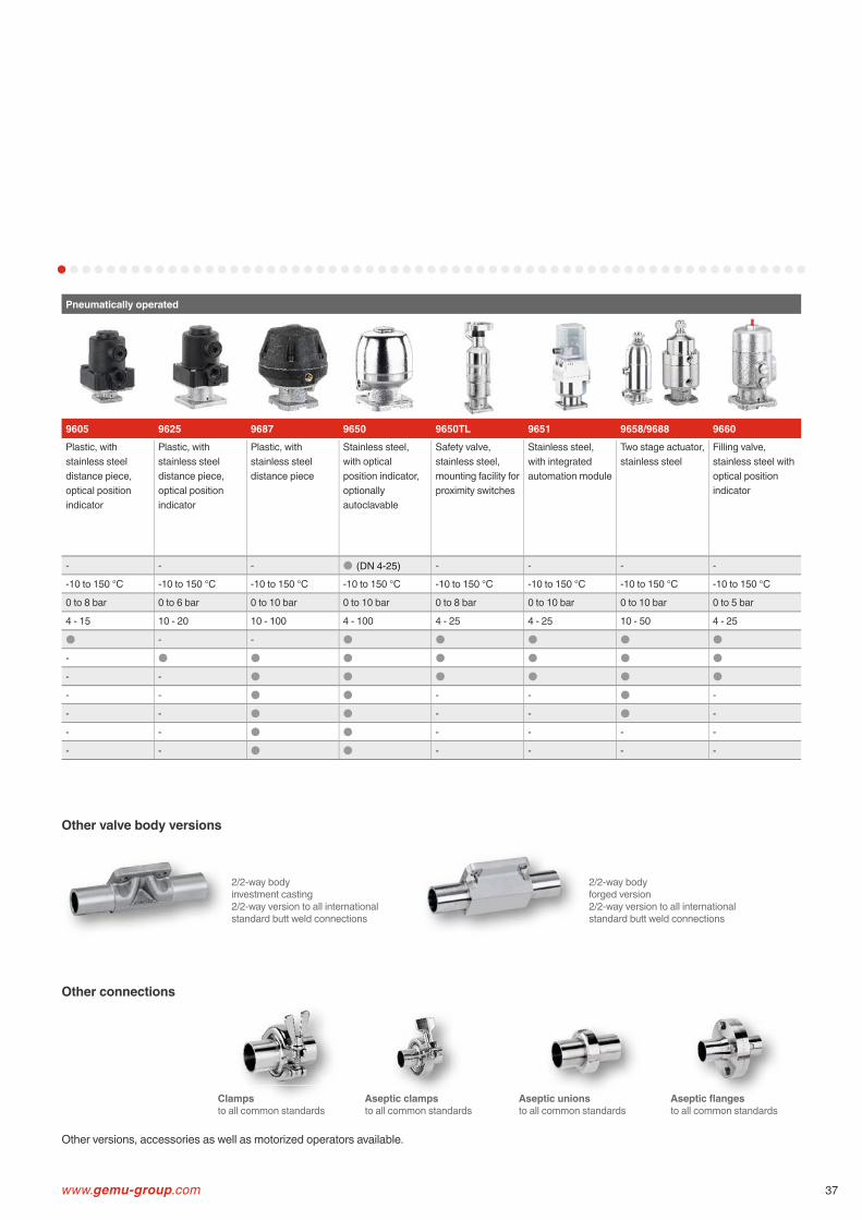
Pneumatically operated
9605 9625 9687 9650 9650TL 9651 9658/9688 9660Plastic, with stainless steel distance piece, optical position indicator
Plastic, with stainless steel distance piece, optical position indicator
Plastic, with stainless steel distance piece
Stainless steel, with optical position indicator, optionally autoclavable
Safety valve, stainless steel, mounting facility for proximity switches
Stainless steel, with integrated automation module
Two stage actuator, stainless steel
Filling valve, stainless steel with optical position indicator
- - - ● (DN 4-25) - - - -
-10 to 150 °C -10 to 150 °C -10 to 150 °C -10 to 150 °C -10 to 150 °C -10 to 150 °C -10 to 150 °C -10 to 150 °C
0 to 8 bar 0 to 6 bar 0 to 10 bar 0 to 10 bar 0 to 8 bar 0 to 10 bar 0 to 10 bar 0 to 5 bar
4 - 15 10 - 20 10 - 100 4 - 100 4 - 25 4 - 25 10 - 50 4 - 25
● - - ● ● ● ● ●- ● ● ● ● ● ● ●- - ● ● ● ● ● ●- - ● ● - - ● -
- - ● ● - - ● -
- - ● ● - - - -
- - ● ● - - - -
Other valve body versions
Other connections
2/2-way bodyinvestment casting2/2-way version to all international standard butt weld connections
2/2-way bodyforged version2/2-way version to all international standard butt weld connections
www.gemu-group.com 37
Other versions, accessories as well as motorized operators available.
Aseptic unionsto all common standards
Aseptic clampsto all common standards
Aseptic fl angesto all common standards
tic clampsClampsto all common standards

Motorized
Type 9618 9698
Features
Plastic, with stainless steel distance piece, optical position indicator
Plastic, with stainless steel distance piece, optical position indicator and manual override
Autoclavable - -
Operating temperature* 0 to 130 °C 0 to 150 °C
Operating pressure* 0 to 6 bar 0 to 10 bar
DN 4 - 15 15 - 50
Supply voltage 24 VAC, 120 VAC, 230 VAC, 50/60Hz
24 VAC, 120 VAC, 230 VAC, 50/60Hz
Diaphragm size 8 ● -
Diaphragm size 10 ● -
Diaphragm size 25 - ●Diaphragm size 40 - ●Diaphragm size 50 - ●Diaphragm size 80 - -
Diaphragm size 100 - -
* dependent on diaphragm material
38
Selection of operators
www.gemu-group.com 39
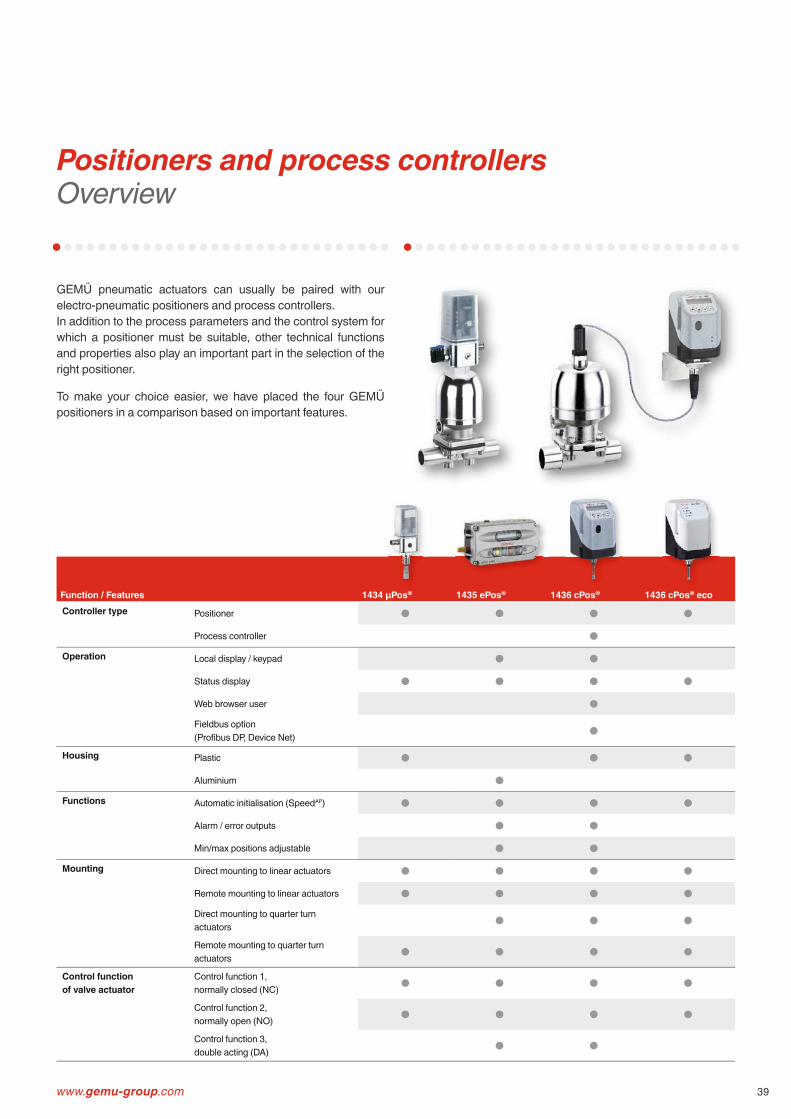
Function / Features 1434 μPos® 1435 ePos® 1436 cPos® 1436 cPos® ecoController type Positioner ● ● ● ●
Process controller ●
Operation Local display / keypad ● ●
Status display ● ● ● ●
Web browser user ●
Fieldbus option (Profi bus DP, Device Net) ●
Housing Plastic ● ● ●
Aluminium ●
Functions Automatic initialisation (SpeedAP) ● ● ● ●
Alarm / error outputs ● ●
Min/max positions adjustable ● ●
Mounting Direct mounting to linear actuators ● ● ● ●
Remote mounting to linear actuators ● ● ● ●
Direct mounting to quarter turn actuators ● ● ●
Remote mounting to quarter turn actuators ● ● ● ●
Control function of valve actuator
Control function 1, normally closed (NC) ● ● ● ●
Control function 2, normally open (NO) ● ● ● ●
Control function 3, double acting (DA) ● ●
Positioners and process controllersOverview
GEMÜ pneumatic actuators can usually be paired with our electro-pneumatic positioners and process controllers.In addition to the process parameters and the control system for which a positioner must be suitable, other technical functions and properties also play an important part in the selection of the right positioner.
To make your choice easier, we have placed the four GEMÜ positioners in a comparison based on important features.
40
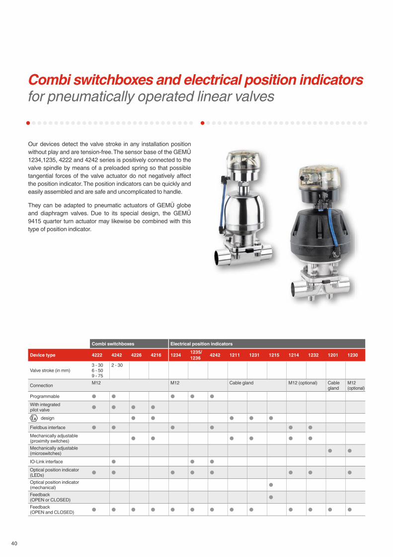
Combi switchboxes and electrical position indicators for pneumatically operated linear valves
Our devices detect the valve stroke in any installation position without play and are tension-free. The sensor base of the GEMÜ 1234,1235, 4222 and 4242 series is positively connected to the valve spindle by means of a preloaded spring so that possible tangential forces of the valve actuator do not negatively aff ect the position indicator. The position indicators can be quickly and easily assembled and are safe and uncomplicated to handle.
They can be adapted to pneumatic actuators of GEMÜ globe and diaphragm valves. Due to its special design, the GEMÜ 9415 quarter turn actuator may likewise be combined with this type of position indicator.
Combi switchboxes Electrical position indicators
Device type 4222 4242 4226 4216 1234 1235/1236 4242 1211 1231 1215 1214 1232 1201 1230
Valve stroke (in mm)3 - 306 - 509 - 75
2 - 30
Connection M12 M12 Cable gland M12 (optional) Cable gland
M12 (optional)
Programmable ● ● ● ● ●With integrated pilot valve ● ● ● ●
design ● ● ● ● ●Fieldbus interface ● ● ● ● ● ●Mechanically adjustable (proximity switches) ● ● ● ● ● ●Mechanically adjustable (microswitches) ● ●
IO-Link interface ● ● ●Optical position indicator (LEDs) ● ● ● ● ● ● ● ●Optical position indicator (mechanical) ●Feedback(OPEN or CLOSED) ●Feedback (OPEN and CLOSED) ● ● ● ● ● ● ● ● ● ● ● ● ●

www.gemu-group.com 41
Specifi cation of tank valves
The enormous consequential costs which may be incurred as a result of errors in the planning of production plant more than justify increased planning eff orts. Delays and extra costs in validation, late commissioning, contaminated batches, later modifi cations to the plant are just a few of the points in favour of precise planning.
Good planning of the valve designs begins in the project stage. The implementation of complex process sequences demands a wide variety of compact valve designs. GEMÜ places great emphasis on ensuring you get the optimum tank valve for your specifi c application and not any standard solution from the catalogue. It is therefore important that you give us all the relevant information in the project phase. The GEMÜ specifi cation sheet is a great help here.
Please use only one form for each tank valve and proceed as follows to fi ll in the specifi cation:
1. Enter the operating conditions and desired materials.
2. Please state what functions the tank valve should fulfi l.Draw a pictogram or functional diagram and insert it in the specifi cation. You can of course use the examples shown in this brochure as a guide.
3. Label all connection spigots starting with S1, all valve seats starting with V1.
4. Assign the necessary features to every connection in the table and and add explanatory remarks where necessary.
5. Specify the necessary operator and type as well as control function for every connection.
6. For extra remarks and descriptions, you can use an additional sheet.

42
B600 tank valves specifi cationPlease complete this form and return it to your nearest GEMÜ offi ce or to the address listed below!
Example: B600 03-02.AImportant:
S1
V1 V2S3/ H
S2
Contact (GEMÜ)Customer
H V
Operating pressure: bar
Medium temperature: °C
Material of tank valve body:
Diaphragm material:
Code
Code
Surface of tank valve body:
Quantity:
SP
Spigot OperatorSpigot no. Code
S3S4 V3S5 V4
Task no.
43
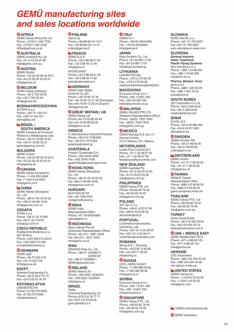
AFRICA GEMÜ Valves Africa Pty. LtdPhone: +27(0)11 462 7795Fax: +27(0)11 462 [email protected]
AUSTRALIAGEMÜ Australia Pty. LtdFax: +61-2-43 23 44 [email protected]
AUSTRIAGEMÜ GmbHPhone: +43 22-36 30 43 45-0Fax:+43 22-36 30 43 [email protected]
BELGIUMGEMÜ Valves bvba/sprlPhone: +32 2 702 09 00Fax: +32 2 705 55 [email protected]/HERCEGOVINAALTERA d.o.o.Phone: +387 51 434 311Fax: +387 51 434 [email protected]
BRAZIL / SOUTH AMERICA
GEMÜ Indústria de ProdutosPlásticos e Metalúrgicos Ltda.Phone: +55-41-33 82 24 25Fax: +55-41-33 82 35 [email protected]Ü GmbHPhone: +43-22-36 30 43 45-0Fax:+43 22-36 30 43 [email protected]
CANADAGEMÜ Valves Canada Inc.Phone: +1-450-902-2690Fax: +1-404-3 44 [email protected]
CHINA GEMÜ Valves (Shanghai) Co., LtdPhone: +86-21-64 42 65 52Fax: +86-21-64 89 18 [email protected] d.o.o.Phone. +38 51 23 70 381Fax +38 51 23 70 [email protected] REPUBLICFluidtechnik Bohemia s.r.o.627 00 BrnoPhone: +420 548 213 233-5Fax: +420 548 213 [email protected]
DENMARKGEMÜ ApSPhone: +45 70 222 516 Fax: +45 70 222 [email protected] Engineering Co.Phone: +20-2-33 47 21 57Fax: +20-2-33 03 18 79ESTONIA/LATVIAUAB BIOTECHAPhone +37 85 270 9055Fax +37 85 270 [email protected]
FINLANDGemü OyPhone: +35-89-82-54-14-0Fax: [email protected]
FRANCEGEMÜ S.A.SPhone: +33-3 88 48 21 00Fax: +33-3 88 49 12 [email protected]: +33-3 88 48 21 20Fax: +33-3 88 49 14 [email protected]
GERMANY GEMÜ Gebr. Müller GmbH & Co. KGPhone: +49-79 40-12 30Fax: +49-79 40-12 31 92 (Domestic) Fax:+49-79 40-12 32 24 (Export)[email protected]
GREAT BRITAIN / UK GEMÜ Valves LtdPhone:+44-19 25-82 40 44Fax:+44-19 25-82 80 [email protected]. Stamopoulos Industrial ProductsPhone: +30-210-7798 663Fax: +30-210-7473 [email protected], Guatemala S.A.Phone: +502 2429-0202Fax: +502 [email protected]
HONG KONGGEMÜ Valves (Shanghai) Co., LtdPhone: +86-21-64 42 65 52Fax +86-21-64 89 18 [email protected] Kft.Fax: +36 1306 [email protected]
INDIAGEMÜ IndiaRepresentative Office Phone: [email protected]
INDONESIAGemu Valves Pte Ltd(Indonesia Representative Office)Phone: +62 (21) - 3681 2226Fax +62 (21) - 6231 [email protected] Kala Co., LtdPhone: +98-21- 22096277, 22095187Fax: [email protected]
IRELANDGEMÜ Ireland LtdPhone: +353 (0)21 4232023Fax: +353 (0)21 [email protected] Engineering LtdPhone:+972-3-9 78 77 77Fax:+972-3-9 23 29 [email protected]
ITALYGEMÜ S.r.l.Phone: +39-02-40044080Fax: [email protected] Suntech Co., LtdPhone: +81-52-881-7193Fax: [email protected] BIOTECHAPhone: +370 5 270 90 55Fax: +370 5 270 90 [email protected] Group d.o.o.Phone: +381 13 801 460Fax: +381 63 394 [email protected]
MALAYSIAGEMU VALVES PTE LTD(Malaysia Representative Office)Phone: +(603)- 7832 7640Fax: +(603)- 7832 [email protected]
MEXICOGEMU Valvulas S.A. de C.V.German Centre 01210 Mexico, D.F., MexicoNETHERLANDSInrada Flow Controls B.V.Phone: +31-1 02 08 07 00Fax: +31-1 02 08 07 [email protected] ZEALANDGEMÜ Australia Pty.Phone: +61-2-43-23 44 93Fax: +61-2-43-23 44 [email protected]Ü Valves PTE. LtdPhone: +65-65 62 76 40Fax: +65-65 62 76 [email protected] Sp. Z. o.oPhone: +48-61-8 20 51 45Fax: +48-61-8 20 69 [email protected] Industriais, LdaPhone: +351-21-4 20 39 00Fax: +351-21-4 20 39 [email protected] String S.R.L. RomaniaPhone: +40 238 72 62 80Fax: +40 238 71 58 [email protected]
RUSSIA OOO „GEMÜ GmbH“Phone: +7 495 980 26 56Fax: +7 495 980 26 [email protected] Eurocons Group d.o.o.Phone: +381 13 801 460Fax: +381 13 837 [email protected]
SINGAPOREGEMÜ Valves PTE. LtdPhone: +65-65 62 76 40Fax: +65-65 62 76 [email protected]
SLOVAKIAEURO-VALVE s.r.o.Phone. +421 31 705 5007Fax +421 31 705 [email protected] SLOVENIAGeneral Industry, Water Treatment, Plastic Piping Systems Strix Inziniring d.o.o.Phone: +386 1 54 66 050Fax: +386 1 54 66 [email protected], Biotech, Food Ipros d.o.o.Phone: +386 1 200 26 20Fax: +386 1 423 18 [email protected] KOREAJID Corporation Co. LtdPhone: +82-2-326-5545Fax: [email protected], S.A.Phone: +34-9-32 982 000Fax: +34-9-34 311 [email protected]
SWEDENGEMÜ Armatur ABPhone: +46-31-99 65 00Fax: +46-31-99 65 [email protected]
SWITZERLANDGEMÜ GmbH Phone: +41-41-7 99 05 05Fax: +41-41-7 99 05 [email protected]
TAIWANGEMUE Taiwan Representative OfficePhone: +886-3-3 56 68 50Fax: +886-3-3 56 68 [email protected]Ü Valves PTE. LtdPhone: +65-65 62 76 40Fax: +65-65 62 76 [email protected] Çevre Enerji Phone: +90 216 402 20 00Fax: +90 216 402 20 [email protected]
UAE + MIDDLE EASTGEMU Middle East FZCOPhone: +971-4-88 60 125Fax: +971-4-88 60 [email protected] AutomationPhone: +380 (44) 494 33 55Fax: +380 (44) 494 33 [email protected]
UNITED STATESGEMÜ Valves Inc.Phone: +1-678-5 53 34 00Fax: +1-404-3 44 93 [email protected]
GEMÜ manufacturing site
GEMÜ subsidiary
GEMÜ manufacturing sitesand sales locations worldwide

www.gemu-group.com
GEMÜ Gebr. Müller Apparatebau GmbH & Co. KGFritz-Müller-Straße 6-8 · D-74653 Ingelfi ngen-CriesbachPhone +49 (0)7940 123-0 · [email protected]
Subj
ect t
o al
tera
tion
· 09/
2015
· 88
4326
46