b976 lydbrook railway bridge feasibility study · 2017-09-05 · project name lydbrook railway...
TRANSCRIPT

B976 LYDBROOK RAILWAY BRIDGE
FEASIBILITY STUDY
B976 Revision D
August 2017


Project Name Lydbrook Railway Bridge
Document Title Feasibility study
Doc. Ref.:COGL43045784 Rev. D Issued: August 2017
Contents
1 EXECUTIVE SUMMARY ....................................................................................... 1
2 INTRODUCTION ................................................................................................. 3
3 SITE DETAILS ..................................................................................................... 4
3.1 SITE DESCRIPTION AND ACCESS ....................................................................... 4
3.2 ENVIRONMENTAL CONSTRAINTS ....................................................................... 5
3.2.1 NATURAL ENGLAND AND ENVIRONMENT AGENCY ............................................... 5
3.2.2 WYE VALLEY AONB ............................................................................................ 5
4 STRUCTURE DESCRIPTION ................................................................................ 7
4.1 INTRODUCTION ................................................................................................ 7
4.2 CONDITION AND DISCUSSION OF BRIDGE’S ELEMENTS ...................................... 7
4.2.1 TIMBER WALKWAY AND HANDRAILS .................................................................. 8
4.2.2 MAIN LONGITUDINAL GIRDERS ......................................................................... 9
4.2.3 TRANSVERSE GIRDERS .................................................................................... 10
4.2.4 SECONDARY LONGITUDINAL BEAMS ................................................................ 11
4.2.5 PIERS ............................................................................................................. 12
4.2.6 PAINTING SYSTEM .......................................................................................... 13
5 REMEDIAL MEASURES FOR BRIDGE ELEMETNS ............................................... 14
5.1 TIMBER WALWAY AND HANDRAILS .................................................................. 14
5.2 MAIN LONGITUDINAL GIRDERS ....................................................................... 14
5.3 TRANSVERSAL GIRDERS .................................................................................. 14
5.4 SECUNDARY LONGITUDINAL BEAMS ................................................................. 14
5.5 PIERS ............................................................................................................. 14
5.6 PAINT SYSTEM ................................................................................................ 15
6 WORKS OPTIONS ............................................................................................. 16
6.1 INTRODUCTION .............................................................................................. 16
6.2 WORKS REQUIRED TO MAKE THE BRIDGE SAFE ................................................ 16
6.3 WORKS REQUIRED TO DEMOLISH THE STRUCTURE .......................................... 18

Project Name Lydbrook Railway Bridge
Document Title Feasibility study
Doc. Ref.:COGL43045784 Rev. D Issued: August 2017
6.4 WORKS REQUIRED TO REFURBISH THE BRIDGE MAINTAINING THE
SUPERSTRUCTURE .......................................................................................... 19
6.5 WORKS REQUIRED TO REPLACE THE SUPERSTRUCTURE ................................... 21
6.6 WORKS REQUIRED TO BUILT A NEW CABLE SUPPORTED BRIDGE ...................... 22
6.7 WORKS REQUIRED TO REFURBISH THE BRIDGE IN TWO PHASES ...................... 23
6.8 WORKS REQUIRED TO OPERATE A FERRY BOAT ............................................... 25
ANNEX A. COST ESTIMATE AND PROGRAMME FOR DISCUSSED OPTIONS
ANNEX B. DRAWINGS
ANNEX C. PHOTOGRAPHS
ANNEX D. CONTRACTORS CONSULTED
ANNEX E. AUTHORITIES CONSULTED

Project Name Lydbrook Railway Bridge
Document Title Feasibility study
Doc. Ref.:COGL43045784 Rev. D 1 Issued: August 2017
1 EXECUTIVE SUMMARY
On November 2016, Amey was appointed by Gloucestershire County Council (GCC) to carry out a
feasibility study at Lydbrook Railway Bridge. The aim of this study is to identify the necessary
works to refurbish the bridge and upgrade it as a footbridge as well as identify future
maintenance costs of the structure. The installation of a brand new bridge has been considered
too. The ultimate goal of this work is to not just provide a short term but a long term analysis of
the cost to re-open Lydbrook Rail Bridge.
The proposed works to upgrading the bridge are based on structural judgement, awareness of
material properties and behaviour of the structure components and connections, it is necessary to
clarify that a detailed appraisal of the structure is outside the objective of this report and that a
more detailed site investigation and models should be carried out to determine the real structural
capacity of the bridge.
The bridge has been visited by Amey’s engineers to attain an understanding of the structure and
the site. However, neither inspections nor structural surveys have been carried out. The condition
of the elements that form the structure is based on the Principal Inspection report carried out by
XEIAD in March 2016.
The local planning authority (Forest of Dean), the River Wye A.O.N.B as well as environmental
authorities Natural England and Environment Agency have been consulted to identify any
protection entity or environmental figure that could affect the refurbishment works. The site has
been identified as an Area of Outstanding Natural Beauty (AONB), Site of Special Scientific
Interest (SSSI) and Special area of Conservation (SAC). The river Wye is a main river and a
salmon fishing river. Although none of the indicated bodies could prevent the execution of the
proposed works, Gloucestershire County Council must notify the above authorities and apply for
the required permits.
The main results of the study have been summarized in table 1 below:
Project Name Lydbrook Railway Bridge
Document Title Feasibility study
Doc. Ref.:COGL43045784 Rev. D 2 Issued: August 2017
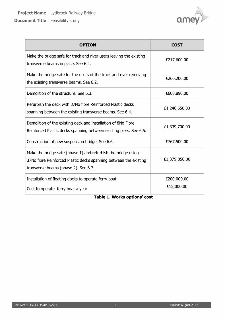
OPTION COST
Make the bridge safe for track and river users leaving the existing
transverse beams in place. See 6.2. £217,600.00
Make the bridge safe for the users of the track and river removing
the existing transverse beams. See 6.2. £260,200.00
Demolition of the structure. See 6.3. £608,890.00
Refurbish the deck with 37No fibre Reinforced Plastic decks
spanning between the existing transverse beams. See 6.4. £1,246,650.00
Demolition of the existing deck and installation of 8No Fibre
Reinforced Plastic decks spanning between existing piers. See 6.5. £1,339,700.00
Construction of new suspension bridge. See 6.6. £767,500.00
Make the bridge safe (phase 1) and refurbish the bridge using
37No fibre Reinforced Plastic decks spanning between the existing
transverse beams (phase 2). See 6.7.
£1,379,850.00
Installation of floating docks to operate ferry boat
Cost to operate ferry boat a year
£200,000.00
£15,000.00
Table 1. Works options’ cost
Project Name Lydbrook Railway Bridge
Document Title Feasibility study
Doc. Ref.:COGL43045784 Rev. D 3 Issued: August 2017
2 INTRODUCTION
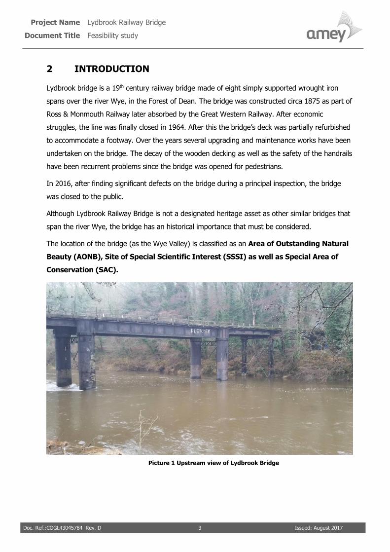
Lydbrook bridge is a 19th century railway bridge made of eight simply supported wrought iron
spans over the river Wye, in the Forest of Dean. The bridge was constructed circa 1875 as part of
Ross & Monmouth Railway later absorbed by the Great Western Railway. After economic
struggles, the line was finally closed in 1964. After this the bridge’s deck was partially refurbished
to accommodate a footway. Over the years several upgrading and maintenance works have been
undertaken on the bridge. The decay of the wooden decking as well as the safety of the handrails
have been recurrent problems since the bridge was opened for pedestrians.
In 2016, after finding significant defects on the bridge during a principal inspection, the bridge
was closed to the public.
Although Lydbrook Railway Bridge is not a designated heritage asset as other similar bridges that
span the river Wye, the bridge has an historical importance that must be considered.
The location of the bridge (as the Wye Valley) is classified as an Area of Outstanding Natural
Beauty (AONB), Site of Special Scientific Interest (SSSI) as well as Special Area of
Conservation (SAC).
Picture 1 Upstream view of Lydbrook Bridge

Project Name Lydbrook Railway Bridge
Document Title Feasibility study
Doc. Ref.:COGL43045784 Rev. D 4 Issued: August 2017
3 SITE DETAILS
3.1 SITE DESCRIPTION AND ACCESS
The bridge spans the river Wye approximately 1.5km northwest from Lydbrook in the Forest of
Dean. At this location, the bridge forms the border between Gloucestershire and Herefordshire
and the ownership of the bridge is shared between both Counties. In 1974 Gloucestershire
County Council and Hereford and Worcester County Council came to a joint agreement for the
maintenance of cross boundary bridges. In the case of Lydbrook Railway Bridge, inspections and
maintenance was to be carried out by Gloucestershire County Council.
Although the bridge provides continuity to the Wye Valley long walk, just the Hereford and
Worcester side of the bridge is declared as a Public right of Way. However, Gloucestershire
County Council has received an application under Section 53 of the Wildlife & Countryside Act
1981 to formally add the route (on the Gloucestershire side) to the Definitive Map of Public Rights
of Way as a public footpath. Initial assessment of the application suggests that there is likely to
be sufficient evidence to show that public footpath rights have “come into being” (largely based
on the amount of user evidence supporting the application, together with the fact that the path is
already dedicated on the Herefordshire side), and as such it should be added to the Definitive
Map of Public Rights of Way. Once the route is added, Gloucestershire County Council will
be legally obliged to provide a permanent path across the river
As part of the Wye Valley long walk, the bridge is important to maintaining the continuity of the
path. A counter installed in the bridge recorded 21,091 pedestrians used between
October 2014 and September 2015 this illustrates the importance of the bridge within the
area.
At the south end, the bridge boundaries an abandoned factory (The Lydbrook Cable Works), the
approaching embankment of the former rail track, and a track (approximately 3.5 wide) that
passes under the structure next to the masonry abutment. This track runs from the Stowfield
Road to a landing stage located approximately 50m west from the bridge.
The bridge is accessed from the track via approach steps made of timber boards backed with
compacted granular material located at the east side of the southern abutment.
At the north, the bridge ends next to a path in a woodland without access for vehicles.

Project Name Lydbrook Railway Bridge
Document Title Feasibility study
Doc. Ref.:COGL43045784 Rev. D 5 Issued: August 2017
Picture 2. Path at north end Picture 3. View from track
3.2 ENVIRONMENTAL CONSTRAINTS
Meetings have been held with Natural England, the Environmental Agency, the Local Authority
(Forest of Dean) and Wye Valley AONB to determine the permits that would be required before
undertaking any works on the bridge.
3.2.1 NATURAL ENGLAND AND ENVIRONMENT AGENCY
According to Natural England, the site falls within three statutory designations, the River Wye Site
of Special Scientific Interest (SSSI), the River Wye Special Area of Conservation (SAC) and in a
Park Wood SSSI on the northern bank. A number of permissions must be granted by Natural
England which will depend on the final nature of the works. As the works would be within a main
river, the Environment Agency must be consulted.
The sort of information to be considered from Natural England and the Environment Agency will
depend on timings (in relation to bats and fish migrations), precautions to ensure works do not
affect the river during operations and safety on site. Usually Natural England and the Environment
Agency ask that the bridge is encapsulated during operations.
According to Natural England, the area is particularly noted for its Lesser Horseshoe Bats
and consideration/appropriate licenses and mitigation must be considered.
Although the above aspects should not be a problem to undertake repairs works on the bridge or
even constructing a new one, an early involvement with the relevant Environmental Agencies is
recommended to help identify all environmental risks and permits to be granted.
3.2.2 WYE VALLEY AONB
As the site is in the Wye Valley AONB contacts with an officer from this body have been made
and they have confirmed that any new structure or refurbishment should enhance the
natural beauty of the site.

Project Name Lydbrook Railway Bridge
Document Title Feasibility study
Doc. Ref.:COGL43045784 Rev. D 6 Issued: August 2017
Back in 2008-2010, a new bridge was proposed over the Wye near Tintern. In this case a public
consultation exercise identified an Underslung Truss design as the preferred option over a Cable
Stayed bridge design. The AONB Joint Advisory Committee (JAC) expressed some
concerns about the Cable Stayed bridge in relation to landscape impacts and a more rigid
Underslung Truss structure was felt to have less impact.
If a new structure is built, it would be necessary to make the existing structure safe for the users
of the right of navigation along the river and the path that crosses under the southern abutment.
The bridge is not a designated heritage asset so technically it is possible to demolish it. However
as the bridge crosses a SAC/SSSI and a public navigation the practicalities of preventing any
objects falling into the river would make these works expensive.
When dealing with historic structures (even if not Listed or Scheduled), unless a true restoration
is intended, it is better that new additions are clearly identifiable as new rather than
trying to hide the modification with a mock-heritage imitation. Therefore a modern
refurbishment could be appropriate but it must still not conflict with the conservation and
enhancement of the AONB.

Project Name Lydbrook Railway Bridge
Document Title Feasibility study
Doc. Ref.:COGL43045784 Rev. D 7 Issued: August 2017
4 STRUCTURE DESCRIPTION
4.1 INTRODUCTION
Lydbrook Railway Bridge was built circa 1875 as part of Ross & Monmouth Railway. The structure
was in service as a railway bridge until 1964 when the line was closed. After that the deck was
partially refurbished to accommodate a footway along its western side. However there are not
records about the exact date when the footway was opened.
The bridge is a simply supported eight-span bridge with a total length of approximately 86.5 m.
The approaching spans (4 along the southern side and 3 along the northern side) are 10m long
with a central span of 16.5 m.
The superstructure is made of a pair of longitudinal built-up wrought iron girders which are simply
supported on the piers. To support the deck, 32 transverse built-up wrought iron beams span
between the longitudinal girders. A pair of longitudinal built-up wrought iron beams are riveted to
the web of the transverse beams. Over these longitudinal beams lay a pair of large timber bulks
which originally supported the single rail track.
The current deck footway, built once the railway line was closed, is made of timber planks that
span between the transverse girders. The timber planks are bolted to the top flange of the
transverse beams. At the western edge of the footway, there is a steel handrail, while at the
eastern end the hand railing is made of wood.
The bridge is used as part of the Wye Valley Walk. However the deterioration of the timber
walkaway has forced the closure of the bridge several times in the past and required maintenance
works to be undertaken. Following a principal inspection of the bridge in March 2016 the structure
was closed and remains so at the time of writing this report.
4.2 CONDITION AND DISCUSSION OF BRIDGE’S ELEMENTS
The appraisal of the different elements that form the bridge, is based on the Principal Inspection
Report carried out by XEIAD in March 2016 as well as site visits carried out by Amey’s Engineers
in November and December 2016.
Project Name Lydbrook Railway Bridge
Document Title Feasibility study
Doc. Ref.:COGL43045784 Rev. D 8 Issued: August 2017
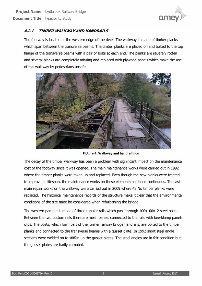
4.2.1 TIMBER WALKWAY AND HANDRAILS
The footway is located at the western edge of the deck. The walkway is made of timber planks
which span between the transverse beams. The timber planks are placed on and bolted to the top
flange of the transverse beams with a pair of bolts at each end. The planks are severely rotten
and several planks are completely missing and replaced with plywood panels which make the use
of this walkway by pedestrians unsafe.
Picture 4. Walkway and handrailings
The decay of the timber walkway has been a problem with significant impact on the maintenance
cost of the footway since it was opened. The main maintenance works were carried out in 1992
where the timber planks were taken up and replaced. Even though the new planks were treated
to improve its lifespan, the maintenance works on these elements has been continuous. The last
main repair works on the walkway were carried out in 2009 where 43 No timber planks were
replaced. The historical maintenance records of the structure make it clear that the environmental
conditions of the site must be considered when refurbishing the bridge.
The western parapet is made of three tubular rails which pass through 100x100x12 steel posts.
Between the two bottom rails there are mesh panels connected to the rails with kee-klamp panels
clips. The posts, which form part of the former railway bridge handrails, are bolted to the timber
planks and connected to the transverse beams with a gusset plate. In 1992 short steel angle
sections were welded on to stiffen up the gusset plates. The steel angles are in fair condition but
the gusset plates are badly corroded.

Project Name Lydbrook Railway Bridge
Document Title Feasibility study
Doc. Ref.:COGL43045784 Rev. D 9 Issued: August 2017
An appraisal of the handrails in 2002 determined that the handrails do not comply with BS
7818:1995 Specification for pedestrian restraint system in metal, on three
dimensional issues, the clear height between the top and the middle horizontal rails, the height
of the top rail above the footpath, and the mesh sizes in the panels between the middle and the
bottom rails. This appraisal found that the parapet is structurally understrength in relation to the
horizontal rails, the angle posts and the strength of the gusset plates.
The eastern parapet is made of timber posts fixed to the timber bulks that previously
supported the rail track and two horizontal wooden rails. The wood is severely rotten and the
posts are loose.
At the eastern edge of the bridge deck there is an unused steel handrail made of two tubular rails
and vertical steel posts. This handrail is completely corroded and its poor stability
represents a risk for members of the public that use the river or the track that passes
underneath the bridge.
Based on the condition of the handrails it is suggested that new pedestrian handrails
complying with current standard should be installed. If it is decided not to refurbish the
bridge, at least the eastern handrail should be removed to prevent its collapse onto the
river or existing track.
4.2.2 MAIN LONGITUDINAL GIRDERS
Although a chemical test has not been carried out to identify the material of the different
elements, considering the time of construction (circa 1875, when the use of mild steel was not a
common practice) and the appearance of the girders (rounded edges, delamination pattern on
rusted areas as well as the absence of steel maker print on the plates), it is thought that the main
girders (as well as the transverse girders and secondary longitudinal girders) are made of
wrought iron.
The girders are built-up girders with plates riveted together. Although the girders are in a general
fair condition the bottom flanges present delamination due to a severe corrosion as well as a
marked distortion induced by rust jacking. The 2016 PI report indicates that slight distortion was
noted at the majority of joints with missing rivets.
Although an accurate survey would be necessary to determinate the actual strain of the plates,
based on the visual appearance of the plates, it is possible to deduce that they have already
reached the yielding point. The distortion of the plates has induced a significant tension in the
rivets. This has implications on the safety of the structure as the elements would have become
more brittle, and therefore its capacity to deform before failure.

Project Name Lydbrook Railway Bridge
Document Title Feasibility study
Doc. Ref.:COGL43045784 Rev. D 10 Issued: August 2017
Picture 5 Detail of rust jacking on longitudinal girder
Considering the stress-strain uncertainty of the bottom flanges and stiffeners and the
consequences that a failure of these elements could have, it is recommended that an
accurate assessment of these elements is undertaken before re-opening the bridge to
the public.
4.2.3 TRANSVERSE GIRDERS
As the main girders, the transverse girders are made up of wrought iron riveted angles and plates
to form fish belly shape sections. The bottom flanges of the transverse girders are riveted to the
top flanges of the main longitudinal girders. These connections are in a fair condition.
However, the top flanges of the transverse girders (where the timber planks are bolted) are badly
corroded with a severe delamination and knife edging (2016 PI estimates a loss of section of 35%
at the top flanges).

Project Name Lydbrook Railway Bridge
Document Title Feasibility study
Doc. Ref.:COGL43045784 Rev. D 11 Issued: August 2017
Picture 6 Detail of corrosion on top flange of transversal girder
Based on the dimension of the transverse beams, it may be said that the carrying
capacity of these elements should be enough to carry the loads imposed by
pedestrians once the top flanges are replaced.
4.2.4 SECONDARY LONGITUDINAL BEAMS
A pair of longitudinal wrought iron built-up girders span between the transverse girders under the
wood bulks. These girders are in fair condition although some connections to the transverse
girders are badly corroded. Although these element had importance when the structure was
designed as a railway bridge (as they carried the load of the rail track), as a footbridge, these
elements are fairly redundant.
Picture 7 Transversal and secondary girders
Project Name Lydbrook Railway Bridge
Document Title Feasibility study
Doc. Ref.:COGL43045784 Rev. D 12 Issued: August 2017
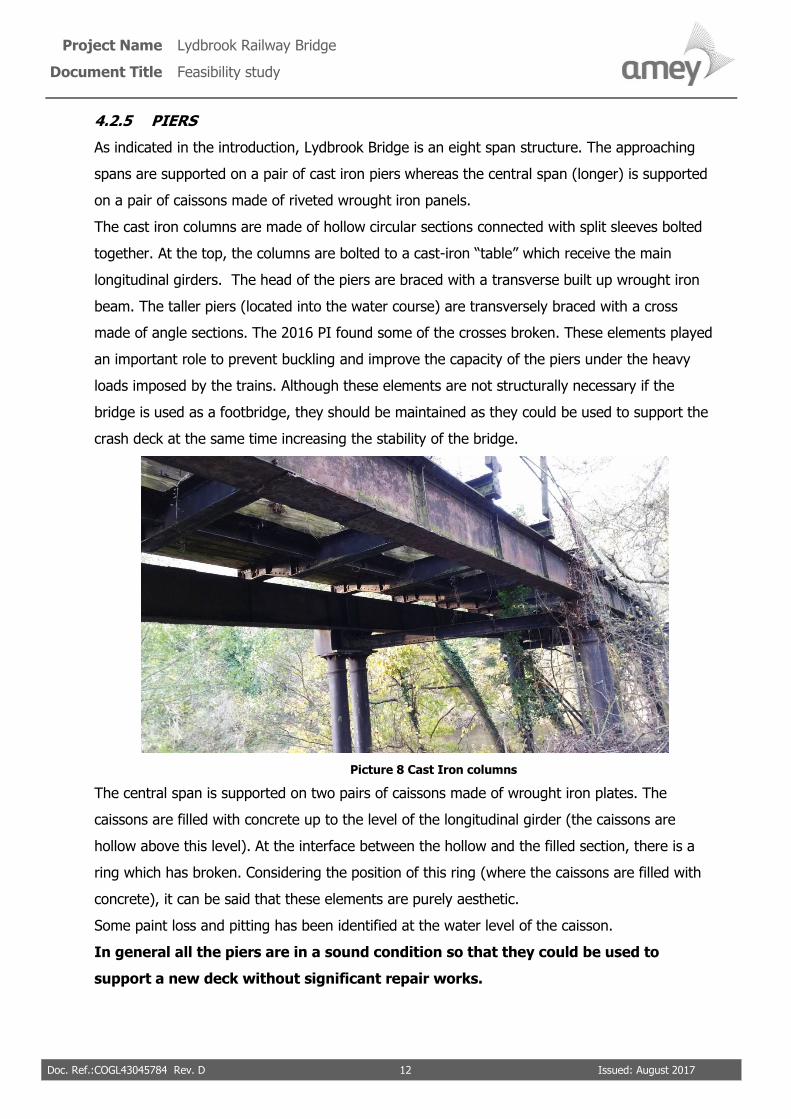
4.2.5 PIERS
As indicated in the introduction, Lydbrook Bridge is an eight span structure. The approaching
spans are supported on a pair of cast iron piers whereas the central span (longer) is supported
on a pair of caissons made of riveted wrought iron panels.
The cast iron columns are made of hollow circular sections connected with split sleeves bolted
together. At the top, the columns are bolted to a cast-iron “table” which receive the main
longitudinal girders. The head of the piers are braced with a transverse built up wrought iron
beam. The taller piers (located into the water course) are transversely braced with a cross
made of angle sections. The 2016 PI found some of the crosses broken. These elements played
an important role to prevent buckling and improve the capacity of the piers under the heavy
loads imposed by the trains. Although these elements are not structurally necessary if the
bridge is used as a footbridge, they should be maintained as they could be used to support the
crash deck at the same time increasing the stability of the bridge.
Picture 8 Cast Iron columns
The central span is supported on two pairs of caissons made of wrought iron plates. The
caissons are filled with concrete up to the level of the longitudinal girder (the caissons are
hollow above this level). At the interface between the hollow and the filled section, there is a
ring which has broken. Considering the position of this ring (where the caissons are filled with
concrete), it can be said that these elements are purely aesthetic.
Some paint loss and pitting has been identified at the water level of the caisson.
In general all the piers are in a sound condition so that they could be used to
support a new deck without significant repair works.

Project Name Lydbrook Railway Bridge
Document Title Feasibility study
Doc. Ref.:COGL43045784 Rev. D 13 Issued: August 2017
Picture 9 Caissons at central span
4.2.6 PAINTING SYSTEM
The paint system is in a general poor condition on the longitudinal and transverse girders. On the
cast-iron piers the painting is in a sound condition while in the central piers (caissons) the
painting system should be replaced in the medium term.
As discussed in previous sections, the corrosion is probably the most important problem that
should be addressed before re-opening the bridge. Removing the rust and providing an
adequate painting system is vital to re-opening the bridge and assure its integrity in
the medium- long term.
Project Name Lydbrook Railway Bridge
Document Title Feasibility study
Doc. Ref.:COGL43045784 Rev. D 14 Issued: August 2017
5 REMEDIAL MEASURES FOR BRIDGE ELEMENTS
5.1 TIMBER WALWAY AND HANDRAILS
As indicated in point 4.2.1 the poor condition of the existing handrails and their failure to meet
the required standards make their replacement the only possible option to open the bridge. The
new handrail must comply with BS 7818:1995 Specification for pedestrian restraint systems in
metal.
5.2 MAIN LONGITUDINAL GIRDERS
To repair the rusting at the bottom flanges of the main longitudinal girders, a combination of
flame cleaning, rivet removal and hammering could be used to get the rust out. However, it is
possible that after removing the rust, a gap may appear between the plates. In this case, an inert
filler material may be required to fill the gap. The replacement material may be recycled wrought
iron or steel depending on the conservation requirements for the bridge.
The repair option described for the existing rusting may be possible if the distortion of the plates
is not critical. Where the plates are badly distorted and delaminated, they may be removed (rivets
drilled out) and replaced using hot set riveting so they can re-fixed.
5.3 TRANSVERSAL GIRDERS
Due to the poor condition of the top flanges it is vital to repair them before opening the bridge.
The first option is to flame cut the top flanges and replace them with back to back bolted steel
sections. After discussing with different contractor about this option, it has been agreed that it
would be cheaper to replace the whole girder with a new steel girder as it would speed up the
process.
5.4 SECONDARY LONGITUDINAL BEAMS
These beams present a sound condition. Therefore the works would be limited to repairing some
connections and repainting them.
5.5 PIERS
As indicated in sections 4.2.5 the piers are structurally sound. In the short term they do not need
any works. However in the long term they would need to be repainted.

Project Name Lydbrook Railway Bridge
Document Title Feasibility study
Doc. Ref.:COGL43045784 Rev. D 15 Issued: August 2017
5.6 PAINT SYSTEM
The paint system of the superstructure presents a poor condition (specially on the main and
transverse girders) and should be repaired before opening the bridge to prevent further
deterioration of the structure
At the time of construction of the structure, oil based paints were common practice; however,
there is a good possibility that the paint system was also based on lead pigments, therefore, the
nature of the system should be determined with a paint survey.
The surface preparation is vital to achieve a good performance of the new paint system. To
remove years of grime, salts and contamination the surface should be first high pressure washed
and then grit blasted. To prevent any blasting residue or paint falling into the river, the structure
must be fully scaffolded and encapsulated.
To increase the lifespan of the paint system, and bearing in mind the high cost of scaffold and grit
blasting the structure, a marine specification paint system is recommended. This system usually
consists of a twin pack zinc rich primer, a zinc rich MIO intermediate coat (this can be 1 or 2 coats
depending on the micron thickness required) and a twin pack polyurethane top coat to whatever
RAL or BS finish colour.

Project Name Lydbrook Railway Bridge
Document Title Feasibility study
Doc. Ref.:COGL43045784 Rev. D 16 Issued: August 2017
6 WORKS OPTIONS
6.1 INTRODUCTION
In this section different alternatives for the bridge are studied. The alternatives have been
discussed with the environment and planning authorities as well as with specialist contractors to
point out the advantages and risks intrinsic to each option.
As will be developed through this section the alternatives considered are:
• Works required to make the bridge safe (for the users of the river and track)
• Works required to demolish the structure.
• Works required to refurbish the bridge maintaining the superstructure.
• Works required to replace the superstructure.
• Works required to build a new cable supported bridge.
• Works required to refurbish the bridge in two phases.
6.2 WORKS REQUIRED TO MAKE THE BRIDGE SAFE
The current condition of the bridge is not safe for the users of the river and the track that crosses
under the southern abutment. The alternatives covered withing this section do not consider re-
opening the bridge but the minimum works that should be undertaken to make the
bridge safe to the users of both river and track.
As discussed in section 4 of this document, the parapet at the eastern end of the deck is in really
poor condition. It has lost its anchorage points to the bridge deck; hence it should be removed to
prevent it falling into the river. Although the western parapet is in better condition and its stability
is not compromised at the moment, it doesn’t meet the standard for a pedestrian restraint
system. Therefore the best option is to remove the western handrails before its deterioration
compromises its stability.
The timber handrails located at the eastern side of the walkway as well as the timber planks and
timber bulks should be removed as they are badly rusted and they can fall into the river and path.
The timber planks that form the walkway must be removed not just to prevent them falling into
the river and track but to dissuade pedestrians using the bridge (even after installing steel fences
at both ends of the bridge, they have been vandalised to enable access to the bridge).
Project Name Lydbrook Railway Bridge
Document Title Feasibility study
Doc. Ref.:COGL43045784 Rev. D 17 Issued: August 2017
Although the wrought iron girders have significant corrosion that will reduce the structural
capacity of the bridge (especially the top flanges of the transverse girders) they are still safely
carrying their self-weight. In the short term the transverse girders may stay in place
(Option 6.2.1) although consideration should be given to removing them in the medium
term.
Considering the safety of public as well as environmental constrains (the bridge is above a water
course) it is necessary to remove the elements which due to their poor condition may fall into the
water and track.
As the bridge spans over a watercourse, preventing any debris or liquid entering the river is a
priority. A crash deck/scaffolding could be suspended from the main girders. The crash deck must
be fire proof to allow flame cutting. The crash deck is an indispensable element in order to obtain
a permit from the Environment Agency. This crash deck must to be perfectly sealed, and any
other option would be rejected by the Environment Agency.
For the span 1 and span 2, a 50 tonne crane could be placed on the existing track to assist with
the operations. However from span 3 to span 8 a temporary platform would need to be installed
between the existing transverse beams. This platform would provide access for a mini crane to
assist with the operations. However, due to the really poor condition of the top flanges of the
transverse beams, it is likely that some strengthening works would be required on the transverse
beams before installing the temporary platform.
Next to both ends of the bridge, there are trees which branches are growing over the structure.
These trees should be trimmed or cut to prevent them falling and damaging the structure.
The main works to make the bridge safe are briefly described below:
• Vegetation clearance/ tree management at both ends of the bridge.
• Installation of scaffold/crash deck under the main longitudinal girders.
• Installation of temporary platform over the bridge
• Remove the existing handrails, timber walkway and timber bulks.
• Remove transverse beams (Option 6.2.2)
• Repair/strengthen the fencing at both sides of the bridge to prevent people entering the
bridge
Refer to Annex A for programme and detail cost for this option.

Project Name Lydbrook Railway Bridge
Document Title Feasibility study
Doc. Ref.:COGL43045784 Rev. D 18 Issued: August 2017
Advantages of the method:
• The proposal represents the cheaper way to make the bridge safe in the short term.
• The works may be considered as an initial phase of a bigger demolition scheme to be
completed in the future. See 6.7.
• The river channel would remain open all the time.
• Minimum use of public track during the works.
Disadvantages of the option:
• The bridge would remain closed.
• Short term solution as further demolition would be needed in the future.
• The remaining elements would need to be monitored to check their condition.
6.3 WORKS REQUIRED TO DEMOLISH THE STRUCTURE
In the long term, unless large sums are set aside to maintain it, the demolition of the
structure will be necessary either if it is decided to build a new bridge or to keep the bridge
closed to the public as its continuous deterioration will eventually make it unsafe.
The demolition of the structure is constrained by the location of the bridge (over a water course)
which requires a number of measures are put in place to prevent objects falling into the river.
Discussions have been held with a specialist demolition contractor and the following method of
work has been proposed:
• Installation of a cofferdam from the southern bank to the pier No 4. The cofferdam would
be filled with rock to form a level platform to operate machines and cranes from. The
access to this platform would be via a ramp excavated into the southern bank.
• A scaffold access/crash deck will need to be installed underneath the main girders, this
will provide access for site operations to remove the handrails, timber planking, bulk
timbers, and cross beams. This crash deck will prevent any debris entering the water
course during dismantling works, and also keep the waterway navigable.
• The bridge walk way timber, handrails and cross girders would be removed with the
scaffold /crash deck in place.
• Before removing the scaffold /crash deck lifting chains will need to be fixed to the beams.

Project Name Lydbrook Railway Bridge
Document Title Feasibility study
Doc. Ref.:COGL43045784 Rev. D 19 Issued: August 2017
• The scaffold access/crash deck will then be removed, and main beams craned down (1
span at a time). The cranes will operate from the cofferdam.
Refer to Annex A for programme and detail cost for this option.
Advantages of method:
• All works to be carried out from one side of the river.
• No additional land required, access track is suitable for plant and machinery.
• All debris to be contained with no debris entering the water course.
• River channel to remain open to the public (apart from during craning operations).
Disadvantages of the method:
• Cutting down of trees to access the river bank.
• Excavation of southern river bank to from a down ramp.
• Restriction of river flow.
• Heavy use of public track for site access.
• A new bridge would need to be installed to maintain the footpath.
6.4 WORKS REQUIRED TO REFURBISH THE BRIDGE MAINTAINING THE
SUPERSTRUCTURE
This option would maintain the piers and main longitudinal girders while the existing
walkway and handrails would need to be removed. A new Fibre Reinforced Plastic (FRP)
deck would be installed over new steel transverse beams.
The main longitudinal beams would be repaired and repainted as indicated in sections 5.2. and
5.6 respectively.
The top flanges of the transverse girders are in a really poor condition. The works to repair the
top flanges (cut and replace them with back to back steel angles) would be more difficult and
expensive than to replace the entire girders with new steel beams. Therefore it is advised that the
transverse girders are replaced.
The new deck would be made off 37 No FRP decks (2.35 m in length and 500 kg of weight) which
would span between the new transverse beams. It would provide pedestrian and cyclist access
with a width of 1.25m with new aluminium handrails to be installed. The width could be increased
to 2.5m to carry light vehicles.

Project Name Lydbrook Railway Bridge
Document Title Feasibility study
Doc. Ref.:COGL43045784 Rev. D 20 Issued: August 2017
At the southern side of the bridge, the access will be improved and the vegetation cleared.
To provide access and allow all the operations, a scaffold /crash deck would need to be installed
under the longitudinal beams and a temporary bridge will be installed to allow a mini crane to
access along the structure to assist with the demolition of the transverse beams and installation
of new beams and decks. The scaffold access/crash deck should be water tight and fire proof.
The main works to be undertaken are summarized below:
• Vegetation clearance/ tree management at both ends of the bridge.
• Installation of scaffolding/crash deck hung from the main longitudinal girders. This
scaffold would provide access to operatives and allow operation to remove handrails,
timber walkway, timber bulks and transverse girders.
• Installation of temporary bridge (platform) over existing transverse beams.
• Remove existing wrought iron transverse beams and replace them with new steel beams.
• Repair bottom flanges of main girders.
• High pressure washing and blast cleaning of main longitudinal girders.
• Repair bottom flanges of main girders. See section 5.2.
• Application of new marine paint system. See section 5.6.
• Installation of No 37 FRP decks.
• Installation of new aluminium handrails conforming to BS7818:1995
• Removal of scaffolding / crash deck
• Remove temporary bridge
• Improve south access.
Refer to Annex A for programme and detail cost for this option.
Advantages of the option:
• The structure would retain its original architecture.
• FRP deck has a really good performance in wet conditions with a design life of 50-60
years requiring minimal maintenance.
• If necessary FRP deck can be designed to carry light vehicles.
Project Name Lydbrook Railway Bridge
Document Title Feasibility study
Doc. Ref.:COGL43045784 Rev. D 21 Issued: August 2017
• The new decking would help to reduce the corrosion of the girders as the main reasons
for the corrosion of the girders is water leaking through the timber planks.
Disadvantages of the option:
• A detailed survey would be required to determine the condition of each element
specifically the splices of the longitudinal girders.
• The structure will need to be modelled to determine its carrying capacity and the
necessary works to repair the wrought iron elements would be difficult and expensive.
• The maintenance of the paint system and wrought iron elements would represent an
important ongoing cost during the life of the structure. (The guaranteed lifespan of the
pain system is about 15 years).
6.5 WORKS REQUIRED TO REPLACE THE SUPERSTRUCTURE
This option is to demolish the whole deck (including main girders) and the installation of
eight simply supported FRP decks between the existing supports. The new deck would
provide adequate access for pedestrians and cyclists with a width of 1.25m. The width could be
increased up to 2.5m to carry light vehicles.
The deck would be made off 7 No FRP units, 10 m in length and 2500kg in weight, which would
span between the approaching piers and 1 FRP unit, 16.5m in length and 3400 kg in weight, at
the central span.
New steel transverse beams would need to be installed at the top of the existing piers to receive
the FRP decks.
A scaffold/crash deck would be required below the deck. The demolition of the first and second
spans would be carried out with a mobile crane positioned at the track. The demolition of the
spans over the river would be undertaken using a telescopic crane which would operate mounted
on a modular pontoon. This pontoon system would be used to install the new FRP decks over the
water course. The first two spans would be installed with a mobile crane from the track.
The main works to be undertaken are summarized below:
• Vegetation clearance/ tree management felling or coppicing at both ends of the bridge.
• Installation of scaffold/crash deck hung from the main longitudinal girders.
• Demolition of spans 1 and 2 using a mobile crane.
• Installation of modular pontoon system.

Project Name Lydbrook Railway Bridge
Document Title Feasibility study
Doc. Ref.:COGL43045784 Rev. D 22 Issued: August 2017
• Demolition of spans 3 to 8 using a crane mounted upon a pontoon system.
• Installation of new FRP decks.
• Installation of new aluminium handrails to standard.
• Demobilise pontoon.
• Removal of scaffold/ crash deck
• Improve south access.
Refer to Annex A for programme and detail cost for this option.
Advantages of the option:
• The new FRP deck would require minimal future maintenance during its working life (50-
60 years)
• It would provide almost a new bridge (just the existing piers would be maintained)
maintaining the structural type of the old bridge.
• If necessary, it would be possible to upgrade the design to enable access for light
vehicles.
Disadvantages of the option:
• The construction process for installing the new deck will be a difficult operation.
• Temporary restriction of river flow during construction.
• The historic value of the structure would not be maintained as the original deck would be
removed and replaced.
• The piers (specially the paint system) would require regular maintenance
6.6 WORKS REQUIRED TO BUILD A NEW CABLE SUPPORTED BRIDGE
This solution involves constructing a new bridge and leaving the existing as it is. In the long term,
this option would require the demolition of the existing structure as its deterioration would
eventually make it unstable and therefore unsafe for the user of the river and path. It should be
noticed however as indicated in section 3.2, there is a precedence in the area when a public
consultation exercise identified an Underslung Truss design as the preferred option over a Cable
Stayed bridge design.
Project Name Lydbrook Railway Bridge
Document Title Feasibility study
Doc. Ref.:COGL43045784 Rev. D 23 Issued: August 2017
To build the foundation for the towers and anchorages a modular pontoon would be used to
reach the northern bank of the river and to install the cables of the bridge. The deck would be
made of a modular truss that can be installed without any temporary works once the cables are in
place. All the elements of the bridge would be made of galvanised steel which eliminate the need
of painting and therefore keep the future maintenance of the structure to a minimum.
The main advantages and disadvantages of this option are described below:
Advantages
• This option would provide a new structure which would reduce the requirement for future
maintenance of the bridge making this a good option in the long term.
Disadvantages
• Aesthetically, a cable supported bridge would have an important impact in landscape
terms.
• Upgrade the design to allow the access for light vehicles would mean a high increase in
the cost of the bridge.
Refer to Annex A for programme and detail cost for this option.
6.7 WORKS REQUIRED TO REFURBISH THE BRIDGE IN TWO PHASES
It is possible that due to financial reasons the refurbishment of the bridge needs to be undertaken
in two phases. It is important that at the end of each phase the structure is left in a safe
condition and ready to complete the next phase.
As indicated in previous sections, the installation of a crash deck is necessary for all the options in
order to obtain a permit from The Environment Agency. The installation of the crash deck
represents an important percentage of the total cost of each option. Therefore, to make
financially feasible the refurbishment of the bridge in two phases, the crash deck should be
installed so it can be left in place during the whole process.
The Environment Agency has been consulted about the feasibility of leaving the crash deck in
place for several years and they have confirmed that the crash deck may be left in place for a
maximum of 3 years as long as that the crash deck is above the associated water level to a 100
year return period event.

Project Name Lydbrook Railway Bridge
Document Title Feasibility study
Doc. Ref.:COGL43045784 Rev. D 24 Issued: August 2017
Two specialist scaffold contractor have been consulted to determine the price to install and
maintain a crash deck during a period of 3 years. Unfortunately it is difficult for them to estimate
the cost for the crash deck without a detailed design. The cost to undertake the design would be
about £4,000 to £5,000. To estimate the cost for the crash deck, it has been assumed that it will
be purchased and inspected monthly when not in use. Once the works are completed the scaffold
may be sold (not considered in the table below).
The main operations required to complete the works in two phases and the associated cost are
summarized in the table below:
PHASE COST
Pre-construction works £66,000.00
Initial works Purchase and install crash deck
(£200,000). Maintain it (£1,500 a month. Total cost assuming 3 years)
£254,000
Phase 1. Minimum works to make the bridge safe. See 6.2.
Complete pre-construction document and design. Mobilise and
demobilise site compound/equipment. Remove existing handrails,
timber walkway and timber bulks. Strengthen the fencing at both
sides of the bridge to prevent people entering the bridge.
£134,000.00
Phase 2. Refurbish the bridge maintaining the superstructure. See 6.4.
Remove existing transverse beams. Paint longitudinal beams and
piers. Installation of new Fibre Reinforced Plastic deck on top of
existing longitudinal girders. Installation of new aluminium handrails.
£925,850.00
TOTAL £1,379,850.00
Table 2. Operations and cost to complete the works in two phases

Project Name Lydbrook Railway Bridge
Document Title Feasibility study
Doc. Ref.:COGL43045784 Rev. D 25 Issued: August 2017
The main advantages and disadvantages of this option are described below:
Advantage
• The total cost can be split out in two financial years which makes it easier from a financial
point of view.
Disadvantages
• The final cost to complete the works is higher than in one single phase.
• The bridge will be maintained closed for a longer period of time.
• The crash deck would need to be inspected/maintained by a competent person.
6.8 WORKS REQUIRED TO OPERATE A FERRY BOAT
Although a ferry boat may be an option to provide a way to cross the river, the water level of the
river Wye at Lydbrook make it difficult to both construct a floating dock and to operate the ferry
boat.
The water level’s range at Lydbrook is a significant constraint to the crossing. According to the
Environment Agency’s records for the river Wye at Lydbrook (Station ID 2196), the normal range
for the water level in average weather conditions is between 0.28m and 2.44m. It has been
between these levels for at least 150 days in the past year. The usual range of the Wye at
Lydbrook in more extreme weather conditions is between 0.42m and 4.00m. It has been between
these levels for 90% of the time since monitoring began. The maximum water level was
registered on 10th February 2014 when the water level reached 5.84m.
As the water level varies, a floating dock will need to be installed at the river banks. After
discussing with a specialist subcontractor on floating docks, the variation of the water level
increases the cost of the dock’s construction and reduces its operation time as it is not always
possible to accommodate the extreme water levels.
To accommodate the average water level (0.28m to 2.44m) it is necessary to install a long
gangway which is mounted on rollers to accommodate the movements. A concrete plinth will be
cast in situ to create a foundation/platform for the rollers.
Project Name Lydbrook Railway Bridge
Document Title Feasibility study
Doc. Ref.:COGL43045784 Rev. D 26 Issued: August 2017
Although the docks would not be operable with water levels above 2.5m, the docks need to be
anchored to big piles to prevent the docks being damaged at high levels, this considerably
increases the construction cost. Although the design and construction cost depends on many
unknowns at this stage, after discussing with contractor it is reasonable to assume a
design/construction cost of £200,000.00.
Although the draught of the boat will depend on the boat design, load etc, it is fair to assume that
a minimum of 1m of water is necessary to allow the navigation, which means that the boat will
not be operable when the water level is low (especially in summer). In addition the navigation will
not be safe under the upper range of the extreme conditions as the speed of the water flow
would compromise safety. Therefore, the ferry boat would be inoperable for a significant numbers
of days a year.
The cost to operate the ferry boat has been estimated at £15,000.00 a year.

Doc. Ref.: COGL43045784 Rev. D Issued August 2017
ANNEX A. COST ESTIMATE AND PROGRAMME FOR THE
DISCUSSED OPTIONS

A
A.1 1 item
B
B.1 1 Item
B.2 1 Item
B.3 1 Item
B.4 8 Weeks
B.5 8 Weeks
B.6 8 Weeks
B.7 8 Weeks
B.8 1 Item
B.9 8 Week
B.10 4 Week
B.11 2 No
B.12 5 No
B.13 1 No
B.14 1 Item
B.15 1 Item
£40,000.00
Total BUDGET Estimate(excluding VAT) £217,600.00
COST
COMPLETION TIME
OPTION
£217,600.00
8 weeks
DESCRIPTION Remove existing parapets, walkway and timber bulks. Vegetation Clearance
6.2.1 Works required to make the bridge safe
PRE-CONSTRUCTION WORKS
CONSTRUCTION WORKS
Preparation of pre‐construction works documents
Item No. Item Description Qty Unit
Temporary works design
Mobilisation.
Site set up ‐ Welfare facilities.
Maintenance of welfare facilities.
Management.
Transport & Travel.
Preliminaries.
Method related costs ‐ Fixed/Temporary works ‐ Scaffold access & safety
netting.
Method related costs ‐ Time related ‐ Provision of safety boat & scaffold
inspections etc
Method related costs ‐ Time related ‐Provision of mini crane & acess bridge.
Carry out general site reinstatements.
Clear site and de‐mobilise all labour, plant, and materials.
Spans 5 ‐ Remove the existing parapets, timber walkway and timber planks.
Span 1 & Span 2 ‐ Remove the existing parapets, timber walkway and timber
planks in span using mobile crane from vehicle track.
Spans 3, 4, 6, 7 & 8 ‐ Remove the existing parapets, timber walkway and timber
planks in span using mini crane & bridge system.
Risk
Strenghtening work on existing transversal beams to allow temporary access over the bridge
CONTINGENCY
A
A.1 1 item
B
B.1 1 Item
B.2 1 Item
B.3 1 Item
B.4 10 Weeks
B.5 10 Weeks
B.6 10 Weeks
B.7 10 Weeks
B.8 1 Item
B.9 10 Week
B.10 8 Week
B.11 2 No
B.12 2 No
B.13 5 No
B.14 5 No
B.15 1 No
B.16 1 Item
B.17 1 Item
Total BUDGET Estimate(excluding VAT) £260,200.00
CONTINGENCY £50,000.00
Span 1 & Span 2 ‐ Remove the existing parapets, timber walkway and
timber planks in span using mobile crane from vehicle track.
Preliminaries.
Method related costs ‐ Fixed/Temporary works ‐ Scaffold access & safety
netting.
Mobilisation.
Site set up ‐ Welfare facilities.
Risk
Strenghtening work on existing transversal beams to allow temporary access over the bridge
Preparation of pre‐construction works documents
CONSTRUCTION WORKS
Span 1 & span 2 ‐ Remove the existing transversal girders
Spans 3, 4, 6, 7 & 8 ‐ Remove the existing parapets, timber walkway and
timber planks in span using mini crane & bridge system.
Spans 3, 4, 6, 7 & 8 ‐ Remove the existing transversal girders
Spans 5 ‐ Remove the existing parapets, timber walkway and timber
planks.
Clear site and de‐mobilise all labour, plant, and materials.
Management.
Carry out general site reinstatements.
Method related costs ‐ Time related ‐ Provision of safety boat & scaffold
inspections etc
Method related costs ‐ Time related ‐Provision of mini crane & acess
bridge.
OPTION
DESCRIPTION
COST
Item No. Item Description
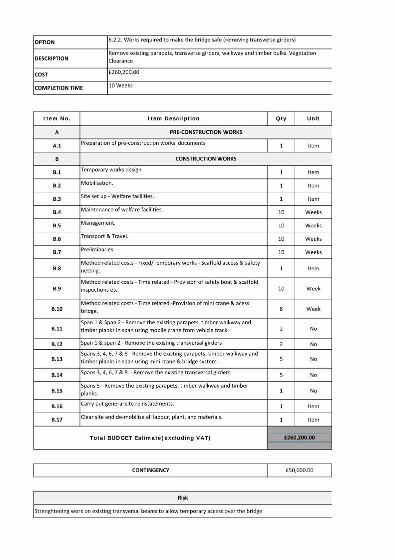
6.2.2. Works required to make the bridge safe (removing transverse girders)
£260,200.00
10 WeeksCOMPLETION TIME
Remove existing parapets, transverse girders, walkway and timber bulks. Vegetation
Clearance
Qty Unit
Transport & Travel.
Temporary works design
Maintenance of welfare facilities.
PRE‐CONSTRUCTION WORKS

A
A.1. 1 item
A.2 1 item
B
B.1 1 item
B.2 1 item
B.3 23 weeks
B.4 1 item
B.5 23 weeks
C
C.1 1 item
C.2 1 item
C.3 1 item
D
D.1 1 item
D.2 1 item
D.3 1 item
D.4 1 item
D.5 1 item
E
E.1 1 item
D
D.1 1 Item
D.2 1 Item
RISKS
External Design Check CAT III
Analysis for any waste removal
Removal of contaminated ground or material
Total BUDGET Estimate(excluding VAT) £608,890.00
£152,222.50CONTINGENCY
Craneage
Crash Deck/Scaffold
Maintenance of Welfare Facilities
DEMOLITION OF BRIDGE DECK
Labour and Plant
Premilinaries
MANAGEMENT, HEALTH AND SAFEY AND SET OUT SITE COMPOUND
Supervision and management
Site set‐up
Credit on recovered scrap metal
COFFER DAM
Carry out general site reinstatements.
Clear site and de‐mobilitation.
Stone fill
Design
Remouve coffer dam
Labour and Plant
DEMOLITION OF BRIDGE COLUMNS
Labour and Plant
Supply & Install Sheet Piles
DEMOLITION OF BRIDGE COLUMNS
COMPLETION TIME
Preparation of permits
Mobilitation
Item No. Item Description Qty Unit
Preparation of tender documents
PRE‐CONSTRUCTION WORKS
CONSTRUCTION WORKS
23Weeks
COST
DESCRIPTION
OPTION 6.3. Works required to demolish the structure
Demolition of the bridge
£608,890.00
A
A.1. 1 item
A.2 1 item
A.3. 1 item
B
B.1 1 Item
B.2 1 Item
B.3 1 Item
B.4 34 Weeks
B.5 34 Weeks
B.6 34 Weeks
B.7 34 Weeks
B.8 1 Item
B.9 34 Week
B.10 15 Week
B.11 2 No
B.12 2 No
B.13 2 No
B.14 5 No
B.15 5 No
B.16 5 No
B.17 1 No
B.18 1 No
B.19 1 No
B.20 1 Item
B.21 1 Items
B.22 1 Item
B.23 1 Item
B.24 1 Item
B.25 1 Item
B.26 1 Item
Total BUDGET Estimate(excluding VAT) £1,246,650.00
CONTINGENCY £249,330.00
Preparation & Painting longitudinal girders and piers.
Spans 5 ‐ Remove the existing transversal girders and replace
them with new to receive new FRP deck
Spans 5 ‐ Install new aluminium parapets.
Repair the bottom flanges of the main girders
Span 1 & 2 Install new aluminium parapets using mobile crane
from vehicle track.
Spans 3, 4, 6, 7 & 8 ‐ Remove the existing parapets, timber
walkway and timber planks in span using mini crane & bridge
system.
Spans 3, 4, 6, 7 & 8 ‐ Remove the existing transversal girders and
replace them with new to receive new FRP deck
Spans 3, 4, 6, 7 & 8 ‐ Install new aluminium parapets using mini
crane & bridge system.
Spans 5 ‐ Remove the existing parapets, timber walkway and
timber planks.
Mobilisation.
Site set up ‐ Welfare facilities.
Maintenance of welfare facilities.
Supervision/Management.
Preparation of tender documents
PRE‐CONSTRUCTION WORKS
CONSTRUCTION WORKS
Item No. Item Description Qty Unit
RISKS
External Design Checks
Transport & Travel.
Preliminaries.
Method related costs ‐ Fixed/Temporary works ‐ Scaffold access &
safety netting.
Method related costs ‐ Time related ‐ Provision of safety boat &
scaffold inspections etc
Method related costs ‐ Time related ‐Provision of mini crane &
acess bridge.
Purchase Aluminium Parapets
Tree surgeon and improve southern access
Carry out general site reinstatements.
Clear site and de‐mobilise all labour, plant, and materials.
Design and delivery of FRP decks
Span 1 & span 2 ‐ Remove the existing transversal girders and
replace them with new to receive new FRP deck
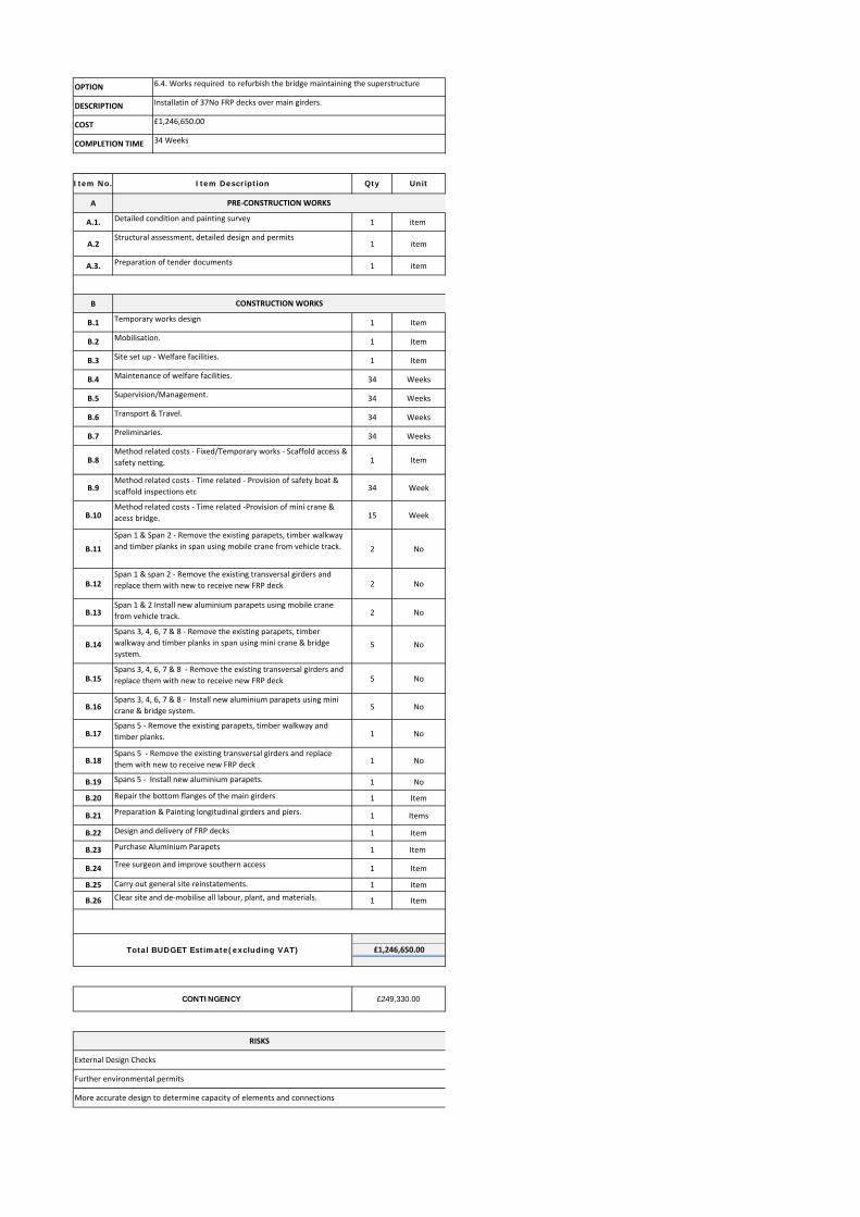
6.4. Works required to refurbish the bridge maintaining the superstructure
Installatin of 37No FRP decks over main girders.
£1,246,650.00
34 Weeks
More accurate design to determine capacity of elements and connections
Temporary works design
Further environmental permits
COMPLETION TIME
OPTION
DESCRIPTION
COST
Detailed condition and painting survey
Structural assessment, detailed design and permits
Span 1 & Span 2 ‐ Remove the existing parapets, timber walkway
and timber planks in span using mobile crane from vehicle track.

A
A.1. 1 item
A.2 1 item
A.3. 1 item
B
B.1 1 Item
B.2 1 Item
B.3 1 Item
B.4 35 Weeks
B.5 35 Weeks
B.6 35 Weeks
B.7 35 Weeks
B.8 1 Item
B.9 35 Week
B.10 35 Week
B.11 2 No
B.12 2 No
B.13 5 No
B.14 5 No
B.15 5 No
B.16 5 No
B.17 1 No
B.18 1 No
B.19 1 No
B.20 1 No
B.21 1 No
B.22 1 No
B.23 2 No
B.24 2 No
B.25 1 No
B.26 2 No
B.27 1 Item
B.28 1 Item
B.29 1 Item
B.30 1 Item
B.31 1 Item
Total BUDGET Estimate(excluding VAT) £1,339,700.00
CONTINGENCY £267,940.00
Clear site and de‐mobilise all labour, plant, including floating plant
Supervision/Management.
Transport & Travel.
Method related costs ‐ Time related ‐ Maintenance of floating plant
Preliminaries.
Method related costs ‐ Fixed/Temporary works ‐ Scaffold access & safety
netting.
Span 1 & 2 ‐ Install transversal beams between piers to receive new
decks using mobile crane from vehicle track.
Span 1 & 2 ‐ Install Fibre Reinforced Plastic decks spanning between the
transversal beams.using mobile crane from vehicle track.
Span 1 & 2 ‐ Install new aluminium parapets.
Spans 3, 4, 6, 7 & 8 ‐ Install Fibre Reinforced Plastic decks spanning
between the transversal beams.
Spans 3, 4, 6, 7 & 8 ‐ Install new aluminium parapets.
Spans 5 ‐ Install transversal beams between piers to receive new decks.
Span 5 ‐ Install Fibre Reinforced Plastic decks spanning between the
transversal beams.
Method related costs ‐ Time related ‐ Provision of safety boat & scaffold
inspections etc
Span 1 & Span 2 ‐ Remove the existing parapets, timber walkway and
timber planks in span using mobile crane from vehicle track.
Span 1 & span 2 ‐ Remove the whole decking and girders including main
longitudinal beams using mobile crane from vehicle track. .
Carry out general site reinstatements.
Temporary works design
Spans 5 ‐Remove the whole decking and girders including main
longitudinal beams using the floating barge.
Spans 3, 4, 6, 7 & 8 ‐ Install transversal beams between piers to receive
new decks.
Spans 3, 4, 6, 7 & 8 ‐ Remove the existing parapets, timber walkway and
timber planks in span using the floating barge.
Spans 5 ‐ Remove the existing parapets, timber walkway and timber
planks.
Spans 3, 4, 6, 7 & 8 ‐ Remove the whole decking and girders including
main longitudinal beams using the floating barge.
Preparation and paint piers
RISKS
OPTION
DESCRIPTION
COST
Preparation of tender documents
Design and manufacture FRP decks
Purchase Aluminium Parapets
Tree surgeon and improve southern access
Pier survey
Piers assessment, detailed design and permits
CONSTRUCTION WORKS
Qty Unit
Site set up ‐ Welfare facilities.
Spans 5 ‐ Install new aluminium parapets.
PRE‐CONSTRUCTION WORKS
Maintenance of welfare facilities.
Further detailed design
6.5. Works required to replace the superstructure
Demolish existing deck and replace it with 8No FRP decks
£1,339,700.00
35 Weeks
External Design Check CAT III
Analysis for any waste removal
Removal of contaminated ground or material
COMPLETION TIME
Mobilisation including floating plant
Item No. Item Description

6.6. Works required to build a new cable supported bridge
A
A.1. 1 item
A.2 1 item
A.3. 1 item
A.3. 1 item
B
B.2 1 Item
B.3 1 Item
B.4 17 Weeks
B.5 17 Weeks
B.6 14 Weeks
B.7 17 Weeks
B.8 1 Item
B.9 2 item
B.10 2 Item
B.11 1 No
B.12 1 No
B.13 1 Item
B.14 1 Item
OPTIONDESCRIPTIONCOST
Suspension bridge
£767,500.00
Preparation of tender documents
COMPLETION TIME
Item No. Item Description Qty
Preparation of permits
17 weeks
PRE‐CONSTRUCTION WORKS
Topo survey
Geo. Survey and Foundation design
Unit
Preliminaries.
CONSTRUCTION WORKS
Mobilisation including floating plant
Site set up ‐ Welfare facilities.
Maintenance of welfare facilities.
Supervision/Management.
Transport & Travel.
Site clearance and stablish suitable acces
Design and manufactgure bridge
Clear site and de‐mobilise all labour, plant,
Completion of foundation and achorage points
Installation of towers
Installation of cables
Installation of truss deck
Total BUDGET Estimate(excluding VAT) £767,500.00
CONTINGENCY £250,000.00
Detailed design Further permits
RISKS
External Design Check CAT III
Analysis for any waste removal
Removal of contaminated ground or material

A
A.1. 1 item
A.2 1 item
A.3. 1 item
B.1 1 Item
B.2 36 weeks
B.2 1 Item
B.3 1 Item
B.4 6 Weeks
B.5 6 Weeks
B.6 6 Weeks
B.7 6 Weeks
B.9 6 Week
B.10 6 Week
B.11 2 No
B.12 5 No
B.13 1 No
B.14 1 Item
B.15 1 Item
B.2 1 Item
B.3 1 Item
B.4 28 Weeks
B.5 28 Weeks
B.6 28 Weeks
B.7 28 Weeks
20 28 Week
B.10 12 Week
B.12 2 No
B.13 2 No
B.15 5 No
B.16 5 No
B.18 1 No
B.19 1 No
B.20 1 Item
B.21 1 Items
B.22 1 Item
B.23 1 Item
B.24 1 Item
B.25 1 Item
B.26 1 Item
Further repair works on longitudinal girders
Purchase Aluminium Parapets
Tree surgeon and improve southern access
Carry out general site reinstatements.
Clear site and de‐mobilise all labour, plant, and materials.
Total BUDGET Estimate(excluding VAT) £1,379,850.00
CONTINGENCY £137,985.00
Maintenance of welfare facilities.
Supervision/Management.
Transport & Travel.
Preliminaries.
Method related costs ‐ Time related ‐ Provision of safety boat & scaffold
inspections etc
Method related costs ‐ Time related ‐Provision of mini crane & acess bridge.
Span 1 & span 2 ‐ Remove the existing transversal girders and replace them
with new to receive new FRP deck
Span 1 & 2 Install new aluminium parapets using mobile crane from vehicle
track.
Spans 3, 4, 6, 7 & 8 ‐ Remove the existing transversal girders and replace
them with new to receive new FRP deck
Spans 5 ‐ Remove the existing transversal girders and replace them with new
to receive new FRP deck
Spans 5 ‐ Install new aluminium parapets.
Repair the bottom flanges of the main girders
Preparation & Painting longitudinal girders and piers.
Design and delivery of FRP decks
PHASE 2. REFURBISH THE BRIDGE MAINTAINING THE SUPERSTRUCTURE
Method related costs ‐ Time related ‐Provision of mini crane & acess bridge.
Span 1 & Span 2 ‐ Remove the existing parapets, timber walkway and timber
planks in span using mobile crane from vehicle track.
Spans 3, 4, 6, 7 & 8 ‐ Remove the existing parapets, timber walkway and
timber planks in span using mini crane & bridge system.
Clear site and de‐mobilise all labour, plant, and materials.
Spans 5 ‐ Remove the existing parapets, timber walkway and timber planks.
Carry out general site reinstatements.
Spans 3, 4, 6, 7 & 8 ‐ Install new aluminium parapets using mini crane &
bridge system.
Mobilisation.
OPTION 6.7. Works required to refurbish the bridge in two phases
DESCRIPTION Make the bridge safe. Installatin of 37No FRP decks over main girders.
COST £1,379,850.00
COMPLETION TIME 6 weeks (phase 1) and 28weeks (phase 2)
Item No. Item Description Qty Unit
PHASE 1
Transport & Travel.
Preliminaries.
Supervision/Maintenance crash deck
Mobilisation.
Site set up ‐ Welfare facilities.
Risk
Strenghtening work on existing transversal beams to allow temporary access over the bridge
PRE‐CONSTRUCTION WORKS
Detailed condition and painting survey
Method related costs ‐ Time related ‐ Provision of safety boat & scaffold
inspections etc
Site set up ‐ Welfare facilities.
Maintenance of welfare facilities.
Management.
PHASE 1 MAKE THE BRIDGE SAFE
Structural assessment, detailed design and permits
INITIAL WORKS. INSTALLATION/MAINTENANCE OF CRASH DECK
Purchase and install crash deck
Preparation of tender documents

6.8. Works required to build two floating docks
A
A.1. 1 item
A.2 1 item
A.3. 1 item
A.3. 1 item
A.4. Design 1 item
B
B.2 1 Item
B.3 1 Item
B.4 8 Weeks
B.5 8 Weeks
B.6 8 Weeks
B.7 8 Weeks
B.8 1 Item
B.9 1 item
2 item
B.10 1 Item
B.11 1 No
OPTIONDESCRIPTION Floating docks
COST £175,600.00
COMPLETION TIME 8 weeks
Item No. Item Description Qty Unit
Transport & Travel.
PRE‐CONSTRUCTION WORKS
Topo survey
Geo. Survey and Foundation design
Preparation of permits
Preparation of tender documents
Sub‐Total
CONSTRUCTION WORKS
Mobilisation
Site set up ‐ Welfare facilities.
Maintenance of welfare facilities.
Supervision/Management.
Preliminaries.
Site clearance and stablish suitable acces
Completion of piles
Docks installation
Purchase docks and gangway
Removal of contaminated ground or material
Further environmental permits
Sub‐Total
Total BUDGET Estimate(excluding VAT) £175,600.00
CONTINGENCY £35,120.00
Completion of concrete plinths
RISKS
Further geotechnical investigation
Analysis for any waste removal

ID Task Name Duration
1 Lydbrook Bridge ‐ Option 6.2.1. Works required to make the bridge safe
44 days
2 Mobilisation including site set up. 5 days
3 Reduce level of vehicle track between Lowmileage abutment and pier No 1.
1 day
4 Install scaffold access walkways along bothupside and downside parapets.
5 days
5 Install safety netting system between all spans.
5 days
6 Span 1 2 days
7 Remove the existing parapets, timber walkway and timber planks in span 1 using mobile crane from vehicle track.
2 days
8 Span 2 3 days
9 Remove the existing parapets, timber walkway and timber planks in span 2 using mobile crane from vehicle track.
2 days
10 Install a temporary bridge system to enable access for a mini crane over spans 1 & 2.
1 day
11 Span 3 3 days
12 Remove the existing parapets, timber walkway and timber planks in span 3 using the mini crane with access along the new temporary bridge deck.
2 days
13 Extend the temporary bridge system to enable access for a mini crane over span 3.
1 day
14 Span 4 3 days
15 Remove the existing parapets, timber walkway and timber planks in span 4 using the mini crane with access along the new temporary bridge deck.
2 days
16 Extend the temporary bridge system to enable access for a mini crane over span 4.
1 day
17 Span 5 3 days
18 Remove the existing parapets, timber walkway and timber planks in span 5 using the mini crane with access along the new temporary bridge deck.
2 days
19 Extend the temporary bridge system to enable access for a mini crane over span 5.
1 day
20 Span 6 3 days
21 Remove the existing parapets, timber walkway and timber planks in span 6 using the mini crane with access along the new temporary bridge deck.
2 days
22 Extend the temporary bridge system to enable access for a mini crane over span 6.
1 day
23 Span 7 3 days
24 Remove the existing parapets, timber walkway and timber planks in span 7 using the mini crane with access along the new temporary bridge deck.
2 days
25 Extend the temporary bridge system to enable access for a mini crane over span 7.
1 day
26 Span 8 3 days
27 Remove the existing parapets, timber walkway and timber planks in span 8 using the mini crane with access along the new temporary bridge deck.
2 days
28 Extend the temporary bridge system to enable access for a mini crane over span 8.
1 day
29 Demobilise and Clear Site. 5 days
S S M T W T F S S M T W T F S S M T W T F S S M T W T F S S M T W T F S S M T W T F S S M T W T F S S M T W T F S06 Feb '17 13 Feb '17 20 Feb '17 27 Feb '17 06 Mar '17 13 Mar '17 20 Mar '17 27 Mar '17
Task
Split
Milestone
Summary
Project Summary
Inactive Task
Inactive Milestone
Inactive Summary
Manual Task
Duration-only
Manual Summary Rollup
Manual Summary
Start-only
Finish-only
External Tasks
External Milestone
Deadline
Progress
Manual Progress
LYDBROOK BRIDGE - OPTION 6.2.1. WORKS REQUIRED TO MAKE THE BRIDGE SAFEOUTLINE PROGRAMME OF WORKS
Page 1
Project: Lydbrook Bridge - Option ADate: Thu 25/05/17
ID Task Name Duration
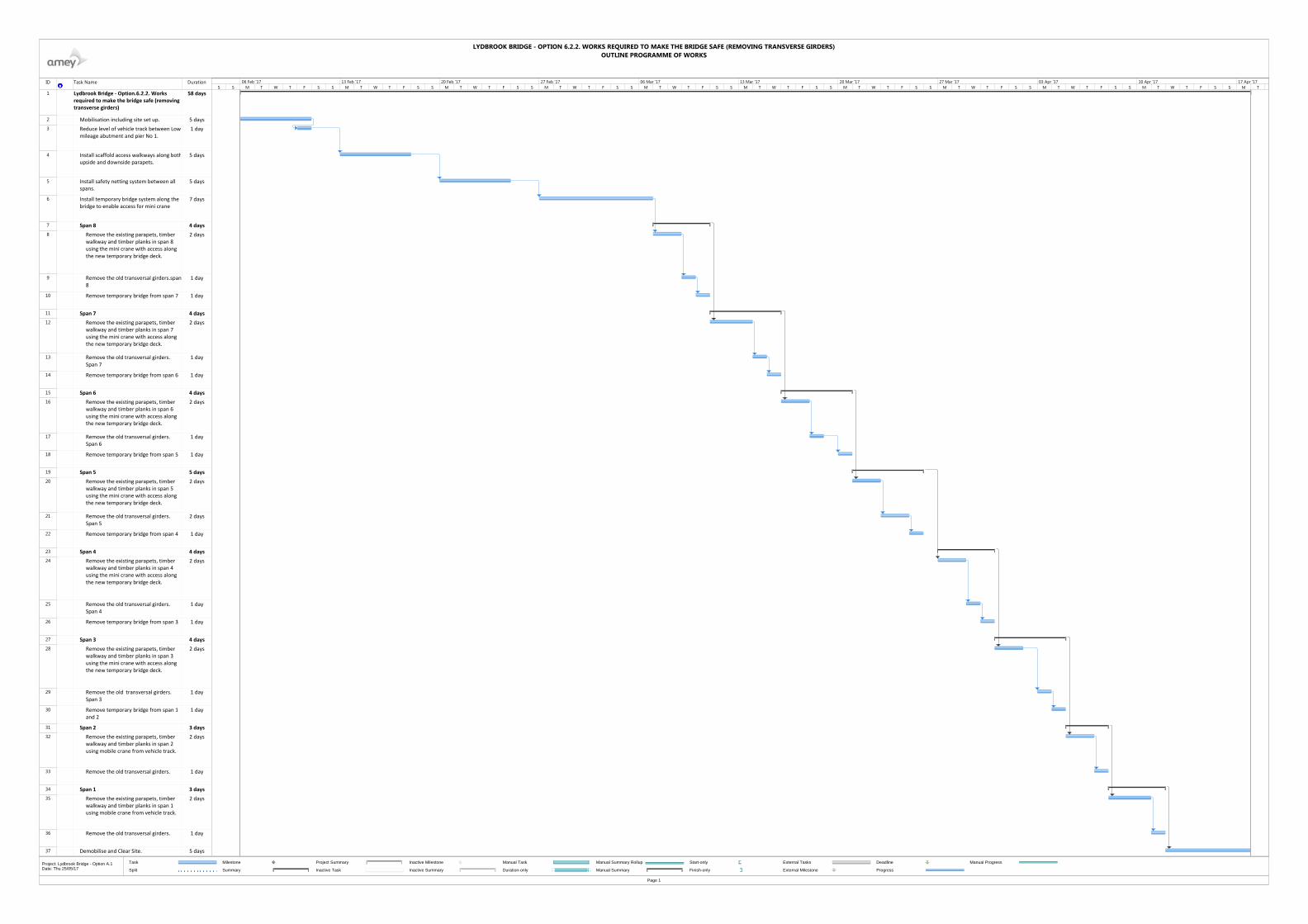
1 Lydbrook Bridge ‐ Option.6.2.2. Works required to make the bridge safe (removing transverse girders)
58 days
2 Mobilisation including site set up. 5 days
3 Reduce level of vehicle track between Lowmileage abutment and pier No 1.
1 day
4 Install scaffold access walkways along bothupside and downside parapets.
5 days
5 Install safety netting system between all spans.
5 days
6 Install temporary bridge system along the bridge to enable access for mini crane
7 days
7 Span 8 4 days
8 Remove the existing parapets, timber walkway and timber planks in span 8 using the mini crane with access along the new temporary bridge deck.
2 days
9 Remove the old transversal girders.span8
1 day
10 Remove temporary bridge from span 7 1 day
11 Span 7 4 days
12 Remove the existing parapets, timber walkway and timber planks in span 7 using the mini crane with access along the new temporary bridge deck.
2 days
13 Remove the old transversal girders. Span 7
1 day
14 Remove temporary bridge from span 6 1 day
15 Span 6 4 days
16 Remove the existing parapets, timber walkway and timber planks in span 6 using the mini crane with access along the new temporary bridge deck.
2 days
17 Remove the old transversal girders. Span 6
1 day
18 Remove temporary bridge from span 5 1 day
19 Span 5 5 days
20 Remove the existing parapets, timber walkway and timber planks in span 5 using the mini crane with access along the new temporary bridge deck.
2 days
21 Remove the old transversal girders. Span 5
2 days
22 Remove temporary bridge from span 4 1 day
23 Span 4 4 days
24 Remove the existing parapets, timber walkway and timber planks in span 4 using the mini crane with access along the new temporary bridge deck.
2 days
25 Remove the old transversal girders. Span 4
1 day
26 Remove temporary bridge from span 3 1 day
27 Span 3 4 days
28 Remove the existing parapets, timber walkway and timber planks in span 3 using the mini crane with access along the new temporary bridge deck.
2 days
29 Remove the old transversal girders. Span 3
1 day
30 Remove temporary bridge from span 1 and 2
1 day
31 Span 2 3 days
32 Remove the existing parapets, timber walkway and timber planks in span 2 using mobile crane from vehicle track.
2 days
33 Remove the old transversal girders. 1 day
34 Span 1 3 days
35 Remove the existing parapets, timber walkway and timber planks in span 1 using mobile crane from vehicle track.
2 days
36 Remove the old transversal girders. 1 day
37 Demobilise and Clear Site. 5 days
S S M T W T F S S M T W T F S S M T W T F S S M T W T F S S M T W T F S S M T W T F S S M T W T F S S M T W T F S S M T W T F S S M T W T F S S M T06 Feb '17 13 Feb '17 20 Feb '17 27 Feb '17 06 Mar '17 13 Mar '17 20 Mar '17 27 Mar '17 03 Apr '17 10 Apr '17 17 Apr '17
Task
Split
Milestone
Summary
Project Summary
Inactive Task
Inactive Milestone
Inactive Summary
Manual Task
Duration-only
Manual Summary Rollup
Manual Summary
Start-only
Finish-only
External Tasks
External Milestone
Deadline
Progress
Manual Progress
LYDBROOK BRIDGE - OPTION 6.2.2. WORKS REQUIRED TO MAKE THE BRIDGE SAFE (REMOVING TRANSVERSE GIRDERS)OUTLINE PROGRAMME OF WORKS
Page 1
Project: Lydbrook Bridge - Option A.1Date: Thu 25/05/17
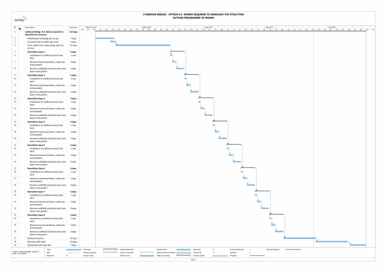
ID Task Name Duration
1 Lydbrook Bridge ‐6.3. Works required to demolish the structure
112 days
2 Mobilisation including site set up. 7 days
3 Cut back trees at coffer dam area 2 days
4 Form coffer dam, sheet piling and rock armour
21 days
5 Demolition Span 1 6 days
6 Installation of scaffold access/crash deck
1 day
7 Remove transversal beams, walk way and parapets
2 days
8 Remove scaffold/crash deck and crane down main girders
3 days
9 Demolition Span 2 6 days
10 Installation of scaffold access/crash deck
1 day
11 Remove transversal beams, walk way and parapets
2 days
12 Remove scaffold/crash deck and crane down main girders
3 days
13 Demolition Span 3 6 days
14 Installation of scaffold access/crash deck
1 day
15 Remove transversal beams, walk way and parapets
2 days
16 Remove scaffold/crash deck and crane down main girders
3 days
17 Demolition Span 4 6 days
18 Installation of scaffold access/crash deck
1 day
19 Remove transversal beams, walk way and parapets
2 days
20 Remove scaffold/crash deck and crane down main girders
3 days
21 Demolition Span 5 6 days
22 Installation of scaffold access/crash deck
1 day
23 Remove transversal beams, walk way and parapets
2 days
24 Remove scaffold/crash deck and crane down main girders
3 days
25 Demolition Span 6 6 days
26 Installation of scaffold access/crash deck
1 day
27 Remove transversal beams, walk way and parapets
2 days
28 Remove scaffold/crash deck and crane down main girders
3 days
29 Demolition Span 7 6 days
30 Installation of scaffold access/crash deck
1 day
31 Remove transversal beams, walk way and parapets
2 days
32 Remove scaffold/crash deck and crane down main girders
3 days
33 Demolition Span 8 6 days
34 Installation of scaffold access/crash deck
1 day
35 Remove transversal beams, walk way and parapets
2 days
36 Remove scaffold/crash deck and crane down main girders
3 days
37 Remove Columns 14 days
38 Remove coffer dam 14 days
39 Demobilise and Clear Site 7 days
29 01 04 07 10 13 16 19 22 25 28 03 06 09 12 15 18 21 24 27 30 02 05 08 11 14 17 20 23 26 29 02 05 08 11 14 17 20 23 26 29 01 04 07 10 13 16 19 22February 2017 March 2017 April 2017 May 2017 June 2017
Task
Split
Milestone
Summary
Project Summary
Inactive Task
Inactive Milestone
Inactive Summary
Manual Task
Duration-only
Manual Summary Rollup
Manual Summary
Start-only
Finish-only
External Tasks
External Milestone
Deadline
Progress
Manual Progress
LYDBROOK BRIDGE - OPTION 6.3. WORKS REQUIRED TO DEMOLISH THE STRUCTUREOUTLINE PROGRAMME OF WORKS
Page 1
Project: Lydbrook Bridge - Option ADate: Thu 25/05/17
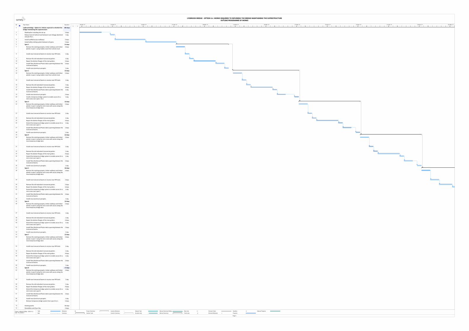
ID Task Name Duration
1 Lydbrook Bridge ‐ Option 6.4. Works required to refurbish the bridge maintaining the superstructure
182 days
2 Mobilisation including site set up. 5 days
3 Reduce level of vehicle track between Low mileage abutmentand pier No 1.
1 day
4 Install scaffold access walkways 5 days
5 Install safety netting system between all spans. 5 days
6 Span 1 11 days
7 Remove the existing parapets, timber walkway and timber planks in span 1 using mobile crane from vehicle track.
2 days
8 Install new transversal beams to receive new FRP deck. 1 day
9 Remove the old redundant transversal girders. 1 day
10 Repair the bottom flanges of the main girders. 4 days
11 Install Fibre Reinforced Plastic decks spanning between thetransversal beams.
2 days
12 Install new aluminium parapets. 1 day
13 Span 2 13 days
14 Remove the existing parapets, timber walkway and timber planks in span 2 using mobile crane from vehicle track.
2 days
15 Install new transversal beams to receive new FRP deck. 1 day
16 Remove the old redundant transversal girders. 1 day
17 Repair the bottom flanges of the main girders. 4 days
18 Install Fibre Reinforced Plastic decks spanning between thetransversal beams.
1 day
19 Install new aluminium parapets. 2 days
20 Install a temporary bridge system to enable access for a mini crane over spans 1 & 2.
1 day
21 Span 3 12 days
22 Remove the existing parapets, timber walkway and timber planks in span 3 using the mini crane with access along thenew temporary bridge deck.
2 days
23 Install new transversal beams to receive new FRP deck. 1 day
24 Remove the old redundant transversal girders. 1 day
25 Repair the bottom flanges of the main girders. 4 days
26 Extend the temporary bridge system to enable access for amini crane over span 3.
1 day
27 Install Fibre Reinforced Plastic decks spanning between thetransversal beams.
2 days
28 Install new aluminium parapets. 1 day
29 Span 4 12 days
30 Remove the existing parapets, timber walkway and timber planks in span 4 using the mini crane with access along thenew temporary bridge deck.
2 days
31 Install new transversal beams to receive new FRP deck. 1 day
32 Remove the old redundant transversal girders. 1 day
33 Repair the bottom flanges of the main girders. 4 days
34 Extend the temporary bridge system to enable access for amini crane over span 4.
1 day
35 Install Fibre Reinforced Plastic decks spanning between thetransversal beams.
2 days
36 Install new aluminium parapets. 1 day
37 Span 5 16 days
38 Remove the existing parapets, timber walkway and timber planks in span 5 using the mini crane with access along thenew temporary bridge deck.
2 days
39 Install new transversal beams to receive new FRP deck. 2 days
40 Remove the old redundant transversal girders. 2 days
41 Repair the bottom flanges of the main girders. 6 days
42 Extend the temporary bridge system to enable access for amini crane over span 5.
1 day
43 Install Fibre Reinforced Plastic decks spanning between thetransversal beams.
2 days
44 Install new aluminium parapets. 1 day
45 Span 6 12 days
46 Remove the existing parapets, timber walkway and timber planks in span 6 using the mini crane with access along thenew temporary bridge deck.
2 days
47 Install new transversal beams to receive new FRP deck. 1 day
48 Remove the old redundant transversal girders. 1 day
49 Repair the bottom flanges of the main girders. 4 days
50 Extend the temporary bridge system to enable access for amini crane over span 6.
1 day
51 Install Fibre Reinforced Plastic decks spanning between thetransversal beams.
2 days
52 Install new aluminium parapets. 1 day
53 Span 7 12 days
54 Remove the existing parapets, timber walkway and timber planks in span 7 using the mini crane with access along thenew temporary bridge deck.
2 days
55 Install new transversal beams to receive new FRP deck. 1 day
56 Remove the old redundant transversal girders. 1 day
57 Repair the bottom flanges of the main girders. 4 days
58 Extend the temporary bridge system to enable access for amini crane over span 7.
1 day
59 Install Fibre Reinforced Plastic decks spanning between thetransversal beams.
2 days
60 Install new aluminium parapets. 1 day
61 Span 8 17 days
62 Remove the existing parapets, timber walkway and timber planks in span 8 using the mini crane with access along thenew temporary bridge deck.
2 days
63 Install new transversal beams to receive new FRP deck. 1 day
64 Remove the old redundant transversal girders. 1 day
65 Repair the bottom flanges of the main girders. 4 days
66 Extend the temporary bridge system to enable access for amini crane over span 8.
1 day
67 Install Fibre Reinforced Plastic decks spanning between thetransversal beams.
2 days
68 Install new aluminium parapets. 1 day
69 Remove temporary bridge system from span 8 to 1. 5 days
70 Painting works 56 days
71 Demobilise and Clear Site. 5 days
S S M T W T F S S M T W T F S S M T W T F S S M T W T F S S M T W T F S S M T W T F S S M T W T F S S M T W T F S S M T W T F S S M T W T F S S M T W T F S S M T W T F S S M T06 Feb '17 13 Feb '17 20 Feb '17 27 Feb '17 06 Mar '17 13 Mar '17 20 Mar '17 27 Mar '17 03 Apr '17 10 Apr '17 17 Apr '17 24 Apr '17 01 May '17
Task
Split
Milestone
Summary
Project Summary
Inactive Task
Inactive Milestone
Inactive Summary
Manual Task
Duration-only
Manual Summary Rollup
Manual Summary
Start-only
Finish-only
External Tasks
External Milestone
Deadline
Progress
Manual Progress
LYDBROOK BRIDGE - OPTION 6.4. WORKS REQUIRED TO REFURBISH THE BRIDGE MAINTAINING THE SUPERSTRUCTUREOUTLINE PROGRAMME OF WORKS
Page 1
Project: Lydbrook Bridge - Option A.1Date: Thu 25/05/17
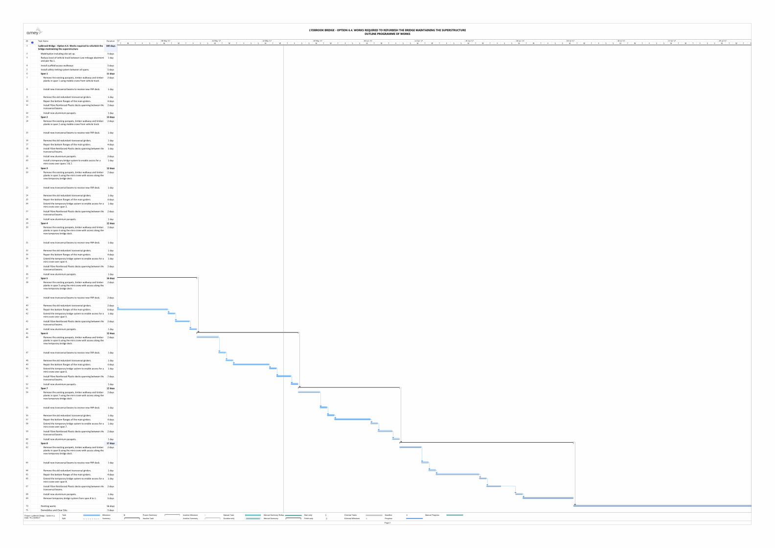
ID Task Name Duration
1 Lydbrook Bridge ‐ Option 6.4. Works required to refurbish the bridge maintaining the superstructure
182 days
2 Mobilisation including site set up. 5 days
3 Reduce level of vehicle track between Low mileage abutmentand pier No 1.
1 day
4 Install scaffold access walkways 5 days
5 Install safety netting system between all spans. 5 days
6 Span 1 11 days
7 Remove the existing parapets, timber walkway and timber planks in span 1 using mobile crane from vehicle track.
2 days
8 Install new transversal beams to receive new FRP deck. 1 day
9 Remove the old redundant transversal girders. 1 day
10 Repair the bottom flanges of the main girders. 4 days
11 Install Fibre Reinforced Plastic decks spanning between thetransversal beams.
2 days
12 Install new aluminium parapets. 1 day
13 Span 2 13 days
14 Remove the existing parapets, timber walkway and timber planks in span 2 using mobile crane from vehicle track.
2 days
15 Install new transversal beams to receive new FRP deck. 1 day
16 Remove the old redundant transversal girders. 1 day
17 Repair the bottom flanges of the main girders. 4 days
18 Install Fibre Reinforced Plastic decks spanning between thetransversal beams.
1 day
19 Install new aluminium parapets. 2 days
20 Install a temporary bridge system to enable access for a mini crane over spans 1 & 2.
1 day
21 Span 3 12 days
22 Remove the existing parapets, timber walkway and timber planks in span 3 using the mini crane with access along thenew temporary bridge deck.
2 days
23 Install new transversal beams to receive new FRP deck. 1 day
24 Remove the old redundant transversal girders. 1 day
25 Repair the bottom flanges of the main girders. 4 days
26 Extend the temporary bridge system to enable access for amini crane over span 3.
1 day
27 Install Fibre Reinforced Plastic decks spanning between thetransversal beams.
2 days
28 Install new aluminium parapets. 1 day
29 Span 4 12 days
30 Remove the existing parapets, timber walkway and timber planks in span 4 using the mini crane with access along thenew temporary bridge deck.
2 days
31 Install new transversal beams to receive new FRP deck. 1 day
32 Remove the old redundant transversal girders. 1 day
33 Repair the bottom flanges of the main girders. 4 days
34 Extend the temporary bridge system to enable access for amini crane over span 4.
1 day
35 Install Fibre Reinforced Plastic decks spanning between thetransversal beams.
2 days
36 Install new aluminium parapets. 1 day
37 Span 5 16 days
38 Remove the existing parapets, timber walkway and timber planks in span 5 using the mini crane with access along thenew temporary bridge deck.
2 days
39 Install new transversal beams to receive new FRP deck. 2 days
40 Remove the old redundant transversal girders. 2 days
41 Repair the bottom flanges of the main girders. 6 days
42 Extend the temporary bridge system to enable access for amini crane over span 5.
1 day
43 Install Fibre Reinforced Plastic decks spanning between thetransversal beams.
2 days
44 Install new aluminium parapets. 1 day
45 Span 6 12 days
46 Remove the existing parapets, timber walkway and timber planks in span 6 using the mini crane with access along thenew temporary bridge deck.
2 days
47 Install new transversal beams to receive new FRP deck. 1 day
48 Remove the old redundant transversal girders. 1 day
49 Repair the bottom flanges of the main girders. 4 days
50 Extend the temporary bridge system to enable access for amini crane over span 6.
1 day
51 Install Fibre Reinforced Plastic decks spanning between thetransversal beams.
2 days
52 Install new aluminium parapets. 1 day
53 Span 7 12 days
54 Remove the existing parapets, timber walkway and timber planks in span 7 using the mini crane with access along thenew temporary bridge deck.
2 days
55 Install new transversal beams to receive new FRP deck. 1 day
56 Remove the old redundant transversal girders. 1 day
57 Repair the bottom flanges of the main girders. 4 days
58 Extend the temporary bridge system to enable access for amini crane over span 7.
1 day
59 Install Fibre Reinforced Plastic decks spanning between thetransversal beams.
2 days
60 Install new aluminium parapets. 1 day
61 Span 8 17 days
62 Remove the existing parapets, timber walkway and timber planks in span 8 using the mini crane with access along thenew temporary bridge deck.
2 days
63 Install new transversal beams to receive new FRP deck. 1 day
64 Remove the old redundant transversal girders. 1 day
65 Repair the bottom flanges of the main girders. 4 days
66 Extend the temporary bridge system to enable access for amini crane over span 8.
1 day
67 Install Fibre Reinforced Plastic decks spanning between thetransversal beams.
2 days
68 Install new aluminium parapets. 1 day
69 Remove temporary bridge system from span 8 to 1. 5 days
70 Painting works 56 days
71 Demobilise and Clear Site. 5 days
T W T F S S M T W T F S S M T W T F S S M T W T F S S M T W T F S S M T W T F S S M T W T F S S M T W T F S S M T W T F S S M T W T F S S M T W T F S S M T W T F S S M T W T F'17 08 May '17 15 May '17 22 May '17 29 May '17 05 Jun '17 12 Jun '17 19 Jun '17 26 Jun '17 03 Jul '17 10 Jul '17 17 Jul '17 24 Jul '17
Task
Split
Milestone
Summary
Project Summary
Inactive Task
Inactive Milestone
Inactive Summary
Manual Task
Duration-only
Manual Summary Rollup
Manual Summary
Start-only
Finish-only
External Tasks
External Milestone
Deadline
Progress
Manual Progress
LYDBROOK BRIDGE - OPTION 6.4. WORKS REQUIRED TO REFURBISH THE BRIDGE MAINTAINING THE SUPERSTRUCTUREOUTLINE PROGRAMME OF WORKS
Page 2
Project: Lydbrook Bridge - Option A.1Date: Thu 25/05/17

ID Task Name Duration
1 Lydbrook Bridge ‐ Option 5.5. Works required to replace the superstructure
192 days
2 Mobilisation including site set up. 5 days
3 Reduce level of vehicle track between Low mileage abutment and pier No 1.
1 day
4 Install scaffold access walkways 5 days
5 Install safety netting system between all spans. 5 days
6 Span 1 7 days
7 Remove the existing parapets, timber walkway and timber planks in span 1 using mobile crane from vehicle track.
2 days
8 Remove the whole decking and girders including main longitudinal beams.
5 days
9 Span 2 7 days
10 Remove the existing parapets, timber walkway and timber planks in span 2 using mobile crane from vehicle track.
2 days
11 Remove the whole decking and girders including main longitudinal beams.
5 days
12 Establish suitable access ramp into the river on the downstream end of bridge.
4 days
13 Mobilise and set up the modular pontoon system on downstream end of bridge.
7 days
14 Span 3 18 days
15 Remove the existing parapets, timber walkway and timber planks in span 3 using the telescopic crane mounted on the barge.
4 days
16 Remove the whole decking and girders including main longitudinal beams.
7 days
17 Install transversal beams between piers to receive new decks.
3 days
18 Install Fibre Reinforced Plastic decks spanning between the transversal beams.
3 days
19 Install new aluminium parapets. 1 day
20 Span 4 18 days
21 Remove the existing parapets, timber walkway and timber planks in span 4 using the telescopic crane mounted on the barge.
4 days
22 Remove the whole decking and girders including main longitudinal beams.
7 days
23 Install transversal beams between piers to receive new decks.
3 days
24 Install Fibre Reinforced Plastic decks spanning between the transversal beams.
3 days
25 Install new aluminium parapets. 1 day
26 Span 5 18 days
27 Remove the existing parapets, timber walkway and timber planks in span 5 using the telescopic crane mounted on the barge.
4 days
28 Remove the whole decking and girders including main longitudinal beams.
7 days
29 Install transversal beams between piers to receive new decks.
3 days
30 Install Fibre Reinforced Plastic decks spanning between the transversal beams.
3 days
31 Install new aluminium parapets. 1 day
32 Span 6 17 days
33 Remove the existing parapets, timber walkway and timber planks in span 6 using the telescopic crane mounted on the barge.
4 days
34 Remove the whole decking and girders including main longitudinal beams.
7 days
35 Install transversal beams between piers to receive new decks.
2 days
36 Install Fibre Reinforced Plastic decks spanning between the transversal beams.
3 days
37 Install new aluminium parapets. 1 day
38 Span 7 18 days
39 Remove the existing parapets, timber walkway and timber planks in span 7 using the telescopic crane mounted on the barge.
4 days
40 Remove the whole decking and girders including main longitudinal beams.
7 days
41 Install transversal beams between piers to receive new decks.
3 days
42 Install Fibre Reinforced Plastic decks spanning between the transversal beams.
3 days
43 Install new aluminium parapets. 1 day
44 Span 8 18 days
45 Remove the existing parapets, timber walkway and timber planks in span 8 using the telescopic crane mounted on the barge.
4 days
46 Remove the whole decking and girders including main longitudinal beams.
7 days
47 Install transversal beams between piers to receive new decks.
3 days
48 Install Fibre Reinforced Plastic decks spanning between the transversal beams.
3 days
49 Install new aluminium parapets. 1 day
50 Demobilise floating plant including reinstatement of slipway ramp on DS end
6 days
51 Span 1 and 2 reconstruction 35 days
52 Install transversal beams between piers to receive new decks.
4 days
53 Install Fibre Reinforced Plastic decks spanning between the transversal beams.
5 days
54 Install new aluminium parapets.. 1 day
55 Paint Piers 25 days
56 Genaral Site Reinstatements, Demobilise and Clear Site. 8 days
S S M T W T F S S M T W T F S S M T W T F S S M T W T F S S M T W T F S S M T W T F S S M T W T F S S M T W T F S S M T W T F S S M T W T F S S M T W T F S S M T W T F S S M T W T F S06 Feb '17 13 Feb '17 20 Feb '17 27 Feb '17 06 Mar '17 13 Mar '17 20 Mar '17 27 Mar '17 03 Apr '17 10 Apr '17 17 Apr '17 24 Apr '17 01 May '17
Task
Split
Milestone
Summary
Project Summary
Inactive Task
Inactive Milestone
Inactive Summary
Manual Task
Duration-only
Manual Summary Rollup
Manual Summary
Start-only
Finish-only
External Tasks
External Milestone
Deadline
Progress
Manual Progress
LYDBROOK BRIDGE - OPTION 6.5. WORKS REQUIRED TO REPLACE THE SUPERSTRUCTUREOUTLINE PROGRAMME OF WORKS
Page 1
Project: Lydbrook Bridge - Option BDate: Thu 25/05/17

ID Task Name Duration
1 Lydbrook Bridge ‐ Option 5.5. Works required to replace the superstructure
192 days
2 Mobilisation including site set up. 5 days
3 Reduce level of vehicle track between Low mileage abutment and pier No 1.
1 day
4 Install scaffold access walkways 5 days
5 Install safety netting system between all spans. 5 days
6 Span 1 7 days
7 Remove the existing parapets, timber walkway and timber planks in span 1 using mobile crane from vehicle track.
2 days
8 Remove the whole decking and girders including main longitudinal beams.
5 days
9 Span 2 7 days
10 Remove the existing parapets, timber walkway and timber planks in span 2 using mobile crane from vehicle track.
2 days
11 Remove the whole decking and girders including main longitudinal beams.
5 days
12 Establish suitable access ramp into the river on the downstream end of bridge.
4 days
13 Mobilise and set up the modular pontoon system on downstream end of bridge.
7 days
14 Span 3 18 days
15 Remove the existing parapets, timber walkway and timber planks in span 3 using the telescopic crane mounted on the barge.
4 days
16 Remove the whole decking and girders including main longitudinal beams.
7 days
17 Install transversal beams between piers to receive new decks.
3 days
18 Install Fibre Reinforced Plastic decks spanning between the transversal beams.
3 days
19 Install new aluminium parapets. 1 day
20 Span 4 18 days
21 Remove the existing parapets, timber walkway and timber planks in span 4 using the telescopic crane mounted on the barge.
4 days
22 Remove the whole decking and girders including main longitudinal beams.
7 days
23 Install transversal beams between piers to receive new decks.
3 days
24 Install Fibre Reinforced Plastic decks spanning between the transversal beams.
3 days
25 Install new aluminium parapets. 1 day
26 Span 5 18 days
27 Remove the existing parapets, timber walkway and timber planks in span 5 using the telescopic crane mounted on the barge.
4 days
28 Remove the whole decking and girders including main longitudinal beams.
7 days
29 Install transversal beams between piers to receive new decks.
3 days
30 Install Fibre Reinforced Plastic decks spanning between the transversal beams.
3 days
31 Install new aluminium parapets. 1 day
32 Span 6 17 days
33 Remove the existing parapets, timber walkway and timber planks in span 6 using the telescopic crane mounted on the barge.
4 days
34 Remove the whole decking and girders including main longitudinal beams.
7 days
35 Install transversal beams between piers to receive new decks.
2 days
36 Install Fibre Reinforced Plastic decks spanning between the transversal beams.
3 days
37 Install new aluminium parapets. 1 day
38 Span 7 18 days
39 Remove the existing parapets, timber walkway and timber planks in span 7 using the telescopic crane mounted on the barge.
4 days
40 Remove the whole decking and girders including main longitudinal beams.
7 days
41 Install transversal beams between piers to receive new decks.
3 days
42 Install Fibre Reinforced Plastic decks spanning between the transversal beams.
3 days
43 Install new aluminium parapets. 1 day
44 Span 8 18 days
45 Remove the existing parapets, timber walkway and timber planks in span 8 using the telescopic crane mounted on the barge.
4 days
46 Remove the whole decking and girders including main longitudinal beams.
7 days
47 Install transversal beams between piers to receive new decks.
3 days
48 Install Fibre Reinforced Plastic decks spanning between the transversal beams.
3 days
49 Install new aluminium parapets. 1 day
50 Demobilise floating plant including reinstatement of slipway ramp on DS end
6 days
51 Span 1 and 2 reconstruction 35 days
52 Install transversal beams between piers to receive new decks.
4 days
53 Install Fibre Reinforced Plastic decks spanning between the transversal beams.
5 days
54 Install new aluminium parapets.. 1 day
55 Paint Piers 25 days
56 Genaral Site Reinstatements, Demobilise and Clear Site. 8 days
S S M T W T F S S M T W T F S S M T W T F S S M T W T F S S M T W T F S S M T W T F S S M T W T F S S M T W T F S S M T W T F S S M T W T F S S M T W T F S S M T W T F S S M T W T F S08 May '17 15 May '17 22 May '17 29 May '17 05 Jun '17 12 Jun '17 19 Jun '17 26 Jun '17 03 Jul '17 10 Jul '17 17 Jul '17 24 Jul '17 31 Jul '17
Task
Split
Milestone
Summary
Project Summary
Inactive Task
Inactive Milestone
Inactive Summary
Manual Task
Duration-only
Manual Summary Rollup
Manual Summary
Start-only
Finish-only
External Tasks
External Milestone
Deadline
Progress
Manual Progress
LYDBROOK BRIDGE - OPTION 6.5. WORKS REQUIRED TO REPLACE THE SUPERSTRUCTUREOUTLINE PROGRAMME OF WORKS
Page 2
Project: Lydbrook Bridge - Option BDate: Thu 25/05/17
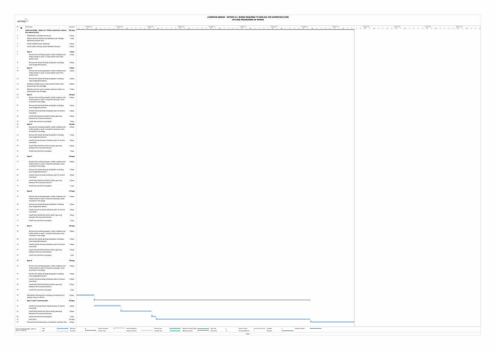
ID Task Name Duration
1 Lydbrook Bridge ‐ Option 5.5. Works required to replace the superstructure
192 days
2 Mobilisation including site set up. 5 days
3 Reduce level of vehicle track between Low mileage abutment and pier No 1.
1 day
4 Install scaffold access walkways 5 days
5 Install safety netting system between all spans. 5 days
6 Span 1 7 days
7 Remove the existing parapets, timber walkway and timber planks in span 1 using mobile crane from vehicle track.
2 days
8 Remove the whole decking and girders including main longitudinal beams.
5 days
9 Span 2 7 days
10 Remove the existing parapets, timber walkway and timber planks in span 2 using mobile crane from vehicle track.
2 days
11 Remove the whole decking and girders including main longitudinal beams.
5 days
12 Establish suitable access ramp into the river on the downstream end of bridge.
4 days
13 Mobilise and set up the modular pontoon system on downstream end of bridge.
7 days
14 Span 3 18 days
15 Remove the existing parapets, timber walkway and timber planks in span 3 using the telescopic crane mounted on the barge.
4 days
16 Remove the whole decking and girders including main longitudinal beams.
7 days
17 Install transversal beams between piers to receive new decks.
3 days
18 Install Fibre Reinforced Plastic decks spanning between the transversal beams.
3 days
19 Install new aluminium parapets. 1 day
20 Span 4 18 days
21 Remove the existing parapets, timber walkway and timber planks in span 4 using the telescopic crane mounted on the barge.
4 days
22 Remove the whole decking and girders including main longitudinal beams.
7 days
23 Install transversal beams between piers to receive new decks.
3 days
24 Install Fibre Reinforced Plastic decks spanning between the transversal beams.
3 days
25 Install new aluminium parapets. 1 day
26 Span 5 18 days
27 Remove the existing parapets, timber walkway and timber planks in span 5 using the telescopic crane mounted on the barge.
4 days
28 Remove the whole decking and girders including main longitudinal beams.
7 days
29 Install transversal beams between piers to receive new decks.
3 days
30 Install Fibre Reinforced Plastic decks spanning between the transversal beams.
3 days
31 Install new aluminium parapets. 1 day
32 Span 6 17 days
33 Remove the existing parapets, timber walkway and timber planks in span 6 using the telescopic crane mounted on the barge.
4 days
34 Remove the whole decking and girders including main longitudinal beams.
7 days
35 Install transversal beams between piers to receive new decks.
2 days
36 Install Fibre Reinforced Plastic decks spanning between the transversal beams.
3 days
37 Install new aluminium parapets. 1 day
38 Span 7 18 days
39 Remove the existing parapets, timber walkway and timber planks in span 7 using the telescopic crane mounted on the barge.
4 days
40 Remove the whole decking and girders including main longitudinal beams.
7 days
41 Install transversal beams between piers to receive new decks.
3 days
42 Install Fibre Reinforced Plastic decks spanning between the transversal beams.
3 days
43 Install new aluminium parapets. 1 day
44 Span 8 18 days
45 Remove the existing parapets, timber walkway and timber planks in span 8 using the telescopic crane mounted on the barge.
4 days
46 Remove the whole decking and girders including main longitudinal beams.
7 days
47 Install transversal beams between piers to receive new decks.
3 days
48 Install Fibre Reinforced Plastic decks spanning between the transversal beams.
3 days
49 Install new aluminium parapets. 1 day
50 Demobilise floating plant including reinstatement of slipway ramp on DS end
6 days
51 Span 1 and 2 reconstruction 35 days
52 Install transversal beams between piers to receive new decks.
4 days
53 Install Fibre Reinforced Plastic decks spanning between the transversal beams.
5 days
54 Install new aluminium parapets.. 1 day
55 Paint Piers 25 days
56 Genaral Site Reinstatements, Demobilise and Clear Site. 8 days
S S M T W T F S S M T W T F S S M T W T F S S M T W T F S S M T W T F S S M T W T F S S M T W T F S S M T W T F S S M T W T F S S M T W T F S S M T W T F S S M T W T F S S M T W T F S07 Aug '17 14 Aug '17 21 Aug '17 28 Aug '17 04 Sep '17 11 Sep '17 18 Sep '17 25 Sep '17 02 Oct '17 09 Oct '17 16 Oct '17 23 Oct '17 30 Oct '17
Task
Split
Milestone
Summary
Project Summary
Inactive Task
Inactive Milestone
Inactive Summary
Manual Task
Duration-only
Manual Summary Rollup
Manual Summary
Start-only
Finish-only
External Tasks
External Milestone
Deadline
Progress
Manual Progress
LYDBROOK BRIDGE - OPTION 6.5. WORKS REQUIRED TO REPLACE THE SUPERSTRUCTUREOUTLINE PROGRAMME OF WORKS
Page 3
Project: Lydbrook Bridge - Option BDate: Thu 25/05/17

ID Task Name Duration
1 Lydbrook Bridge ‐ Option 6.6.Works required to built a new suspension bridge
95 days
2 Mobilisation including site set up. 5 days
3 Establish suitable access ramp into the river
5 days
4 Mobilise and set up modular pontoon system
4 days
5 Foundation. North side 35 days
6 Site clearance. Establish suitable access to northern bank
7 days
7 Foundation and Anchorage blocks 14 days
8 Installation of tower 7 days
9 Foundation Southern bank 12 days
10 Site clearance 2 days
11 Foundation and anchorage blocks. South
10 days
12 Installation of tower 5 days
13 Installation of modular bridge 24 days
14 Cables and vertical lines 10 days
15 Modular deck and parapets 14 days
16 Demobilise floating plant including reinstatement of slipway ramp on DS end
4 days
17 Genaral Site Reinstatements, Demobilise and Clear Site.
10 days
29 01 04 07 10 13 16 19 22 25 28 03 06 09 12 15 18 21 24 27 30 02 05 08 11 14 17 20 23 26 29 02 05 08 11 14 17 20 23 26 29 01February 2017 March 2017 April 2017 May 2017 June
Task
Split
Milestone
Summary
Project Summary
Inactive Task
Inactive Milestone
Inactive Summary
Manual Task
Duration-only
Manual Summary Rollup
Manual Summary
Start-only
Finish-only
External Tasks
External Milestone
Deadline
Progress
Manual Progress
LYDBROOK BRIDGE - OPTION 6.6. WORKS REQUIERD TO BUILD A NEW SUSPENSION BRIDGEOUTLINE PROGRAMME OF WORKS
Page 1
Project: Lydbrook Bridge - Option BDate: Thu 25/05/17
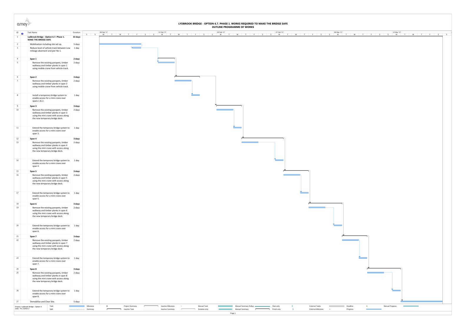
ID Task Name Duration
1 Lydbrook Bridge ‐ Option 6.7. Phase 1. MAKE THE BRIDGE SAFE
33 days
2 Mobilisation including site set up. 5 days
3 Reduce level of vehicle track between Lowmileage abutment and pier No 1.
1 day
4 Span 1 2 days
5 Remove the existing parapets, timber walkway and timber planks in span 1 using mobile crane from vehicle track.
2 days
6 Span 2 3 days
7 Remove the existing parapets, timber walkway and timber planks in span 2 using mobile crane from vehicle track.
2 days
8 Install a temporary bridge system to enable access for a mini crane over spans 1 & 2.
1 day
9 Span 3 3 days
10 Remove the existing parapets, timber walkway and timber planks in span 3 using the mini crane with access along the new temporary bridge deck.
2 days
11 Extend the temporary bridge system to enable access for a mini crane over span 3.
1 day
12 Span 4 3 days
13 Remove the existing parapets, timber walkway and timber planks in span 4 using the mini crane with access along the new temporary bridge deck.
2 days
14 Extend the temporary bridge system to enable access for a mini crane over span 4.
1 day
15 Span 5 3 days
16 Remove the existing parapets, timber walkway and timber planks in span 5 using the mini crane with access along the new temporary bridge deck.
2 days
17 Extend the temporary bridge system to enable access for a mini crane over span 5.
1 day
18 Span 6 3 days
19 Remove the existing parapets, timber walkway and timber planks in span 6 using the mini crane with access along the new temporary bridge deck.
2 days
20 Extend the temporary bridge system to enable access for a mini crane over span 6.
1 day
21 Span 7 3 days
22 Remove the existing parapets, timber walkway and timber planks in span 7 using the mini crane with access along the new temporary bridge deck.
2 days
23 Extend the temporary bridge system to enable access for a mini crane over span 7.
1 day
24 Span 8 3 days
25 Remove the existing parapets, timber walkway and timber planks in span 8 using the mini crane with access along the new temporary bridge deck.
2 days
26 Extend the temporary bridge system to enable access for a mini crane over span 8.
1 day
27 Demobilise and Clear Site. 5 days
S S M T W T F S S M T W T F S S M T W T F S S M T W T F S S M T W T F S S M T W T F S S06 Feb '17 13 Feb '17 20 Feb '17 27 Feb '17 06 Mar '17 13 Mar '17 2
Task
Split
Milestone
Summary
Project Summary
Inactive Task
Inactive Milestone
Inactive Summary
Manual Task
Duration-only
Manual Summary Rollup
Manual Summary
Start-only
Finish-only
External Tasks
External Milestone
Deadline
Progress
Manual Progress
LYDBROOK BRIDGE - OPTION 6.7. PHASE 1. WORKS REQUIRED TO MAKE THE BRIDGE SAFEOUTLINE PROGRAMME OF WORKS
Page 1
Project: Lydbrook Bridge - Option ADate: Thu 25/05/17

ID Task Name Duration
1 Lydbrook Bridge ‐ Option 6.4. Phase2. Works required to refurbish the bridge maintaining the superstructure
154 days
2 Mobilisation including site set up. 5 days
3 Span 1 9 days
4 Install new transversal beams to receive new FRP deck using mobile crane from vehicle track
1 day
5 Remove the old redundant transversal girders. 1 day
6 Repair the bottom flanges of the main girders. 4 days
7 Install Fibre Reinforced Plastic decks spanning between thetransversal beams.
2 days
8 Install new aluminium parapets. 1 day
9 Span 2 10 days
10 Install new transversal beams to receive new FRP deck usinb mobile crane from vehicle track
1 day
11 Remove the old redundant transversal girders. 1 day
12 Repair the bottom flanges of the main girders. 4 days
13 Install Fibre Reinforced Plastic decks spanning between thetransversal beams.
1 day
14 Install new aluminium parapets. 2 days
15 Install a temporary bridge system to enable access for a mini crane over spans 1 & 2.
1 day
16 Span 3 10 days
17 Install new transversal beams to receive new FRP deck. 1 day
18 Remove the old redundant transversal girders. 1 day
19 Repair the bottom flanges of the main girders. 4 days
20 Extend the temporary bridge system to enable access for amini crane over span 3.
1 day
21 Install Fibre Reinforced Plastic decks spanning between thetransversal beams.
2 days
22 Install new aluminium parapets. 1 day
23 Span 4 10 days
24 Install new transversal beams to receive new FRP deck. 1 day
25 Remove the old redundant transversal girders. 1 day
26 Repair the bottom flanges of the main girders. 4 days
27 Extend the temporary bridge system to enable access for amini crane over span 4.
1 day
28 Install Fibre Reinforced Plastic decks spanning between thetransversal beams.
2 days
29 Install new aluminium parapets. 1 day
30 Span 5 14 days
31 Install new transversal beams to receive new FRP deck. 2 days
32 Remove the old redundant transversal girders. 2 days
33 Repair the bottom flanges of the main girders. 6 days
34 Extend the temporary bridge system to enable access for amini crane over span 5.
1 day
35 Install Fibre Reinforced Plastic decks spanning between thetransversal beams.
2 days
36 Install new aluminium parapets. 1 day
37 Span 6 10 days
38 Install new transversal beams to receive new FRP deck. 1 day
39 Remove the old redundant transversal girders. 1 day
40 Repair the bottom flanges of the main girders. 4 days
41 Extend the temporary bridge system to enable access for amini crane over span 6.
1 day
42 Install Fibre Reinforced Plastic decks spanning between thetransversal beams.
2 days
43 Install new aluminium parapets. 1 day
44 Span 7 10 days
45 Install new transversal beams to receive new FRP deck. 1 day
46 Remove the old redundant transversal girders. 1 day
47 Repair the bottom flanges of the main girders. 4 days
48 Extend the temporary bridge system to enable access for amini crane over span 7.
1 day
49 Install Fibre Reinforced Plastic decks spanning between thetransversal beams.
2 days
50 Install new aluminium parapets. 1 day
51 Span 8 15 days
52 Install new transversal beams to receive new FRP deck. 1 day
53 Remove the old redundant transversal girders. 1 day
54 Repair the bottom flanges of the main girders. 4 days
55 Extend the temporary bridge system to enable access for amini crane over span 8.
1 day
56 Install Fibre Reinforced Plastic decks spanning between thetransversal beams.
2 days
57 Install new aluminium parapets. 1 day
58 Remove temporary bridge system from span 8 to 1. 5 days
59 Painting works 56 days
60 Demobilise and Clear Site. 5 days
S S M T W T F S S M T W T F S S M T W T F S S M T W T F S S M T W T F S S M T W T F S S M T W T F S S M T W T F S S M T W T F S S M T W T F S S M T W T F S S M T W T F S S M T W T F S S M T W T F S S M T W06 Feb '17 13 Feb '17 20 Feb '17 27 Feb '17 06 Mar '17 13 Mar '17 20 Mar '17 27 Mar '17 03 Apr '17 10 Apr '17 17 Apr '17 24 Apr '17 01 May '17 08 May '17 15 May '17
Task
Split
Milestone
Summary
Project Summary
Inactive Task
Inactive Milestone
Inactive Summary
Manual Task
Duration-only
Manual Summary Rollup
Manual Summary
Start-only
Finish-only
External Tasks
External Milestone
Deadline
Progress
Manual Progress
LYDBROOK BRIDGE - OPTION 6.4. PHASE 2 WORKS REQUIRED TO REFURBISH THE BRIDGE MAINTAINING THE SUPERSTRUCTUREOUTLINE PROGRAMME OF WORKS
Page 1
Project: Lydbrook Bridge - Option A.1Date: Thu 25/05/17
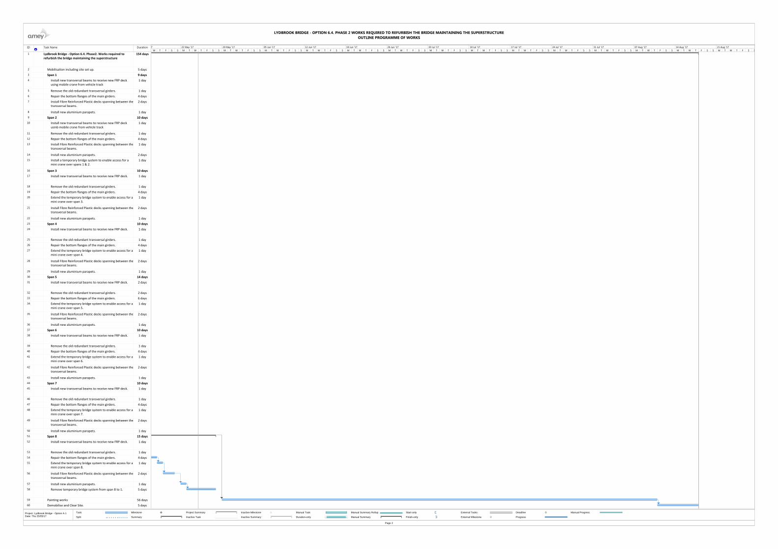
ID Task Name Duration
1 Lydbrook Bridge ‐ Option 6.4. Phase2. Works required to refurbish the bridge maintaining the superstructure
154 days
2 Mobilisation including site set up. 5 days
3 Span 1 9 days
4 Install new transversal beams to receive new FRP deck using mobile crane from vehicle track
1 day
5 Remove the old redundant transversal girders. 1 day
6 Repair the bottom flanges of the main girders. 4 days
7 Install Fibre Reinforced Plastic decks spanning between thetransversal beams.
2 days
8 Install new aluminium parapets. 1 day
9 Span 2 10 days
10 Install new transversal beams to receive new FRP deck usinb mobile crane from vehicle track
1 day
11 Remove the old redundant transversal girders. 1 day
12 Repair the bottom flanges of the main girders. 4 days
13 Install Fibre Reinforced Plastic decks spanning between thetransversal beams.
1 day
14 Install new aluminium parapets. 2 days
15 Install a temporary bridge system to enable access for a mini crane over spans 1 & 2.
1 day
16 Span 3 10 days
17 Install new transversal beams to receive new FRP deck. 1 day
18 Remove the old redundant transversal girders. 1 day
19 Repair the bottom flanges of the main girders. 4 days
20 Extend the temporary bridge system to enable access for amini crane over span 3.
1 day
21 Install Fibre Reinforced Plastic decks spanning between thetransversal beams.
2 days
22 Install new aluminium parapets. 1 day
23 Span 4 10 days
24 Install new transversal beams to receive new FRP deck. 1 day
25 Remove the old redundant transversal girders. 1 day
26 Repair the bottom flanges of the main girders. 4 days
27 Extend the temporary bridge system to enable access for amini crane over span 4.
1 day
28 Install Fibre Reinforced Plastic decks spanning between thetransversal beams.
2 days
29 Install new aluminium parapets. 1 day
30 Span 5 14 days
31 Install new transversal beams to receive new FRP deck. 2 days
32 Remove the old redundant transversal girders. 2 days
33 Repair the bottom flanges of the main girders. 6 days
34 Extend the temporary bridge system to enable access for amini crane over span 5.
1 day
35 Install Fibre Reinforced Plastic decks spanning between thetransversal beams.
2 days
36 Install new aluminium parapets. 1 day
37 Span 6 10 days
38 Install new transversal beams to receive new FRP deck. 1 day
39 Remove the old redundant transversal girders. 1 day
40 Repair the bottom flanges of the main girders. 4 days
41 Extend the temporary bridge system to enable access for amini crane over span 6.
1 day
42 Install Fibre Reinforced Plastic decks spanning between thetransversal beams.
2 days
43 Install new aluminium parapets. 1 day
44 Span 7 10 days
45 Install new transversal beams to receive new FRP deck. 1 day
46 Remove the old redundant transversal girders. 1 day
47 Repair the bottom flanges of the main girders. 4 days
48 Extend the temporary bridge system to enable access for amini crane over span 7.
1 day
49 Install Fibre Reinforced Plastic decks spanning between thetransversal beams.
2 days
50 Install new aluminium parapets. 1 day
51 Span 8 15 days
52 Install new transversal beams to receive new FRP deck. 1 day
53 Remove the old redundant transversal girders. 1 day
54 Repair the bottom flanges of the main girders. 4 days
55 Extend the temporary bridge system to enable access for amini crane over span 8.
1 day
56 Install Fibre Reinforced Plastic decks spanning between thetransversal beams.
2 days
57 Install new aluminium parapets. 1 day
58 Remove temporary bridge system from span 8 to 1. 5 days
59 Painting works 56 days
60 Demobilise and Clear Site. 5 days
W T F S S M T W T F S S M T W T F S S M T W T F S S M T W T F S S M T W T F S S M T W T F S S M T W T F S S M T W T F S S M T W T F S S M T W T F S S M T W T F S S M T W T F S S M T W T F S S M T W T F S S7 22 May '17 29 May '17 05 Jun '17 12 Jun '17 19 Jun '17 26 Jun '17 03 Jul '17 10 Jul '17 17 Jul '17 24 Jul '17 31 Jul '17 07 Aug '17 14 Aug '17 21 Aug '17
Task
Split
Milestone
Summary
Project Summary
Inactive Task
Inactive Milestone
Inactive Summary
Manual Task
Duration-only
Manual Summary Rollup
Manual Summary
Start-only
Finish-only
External Tasks
External Milestone
Deadline
Progress
Manual Progress
LYDBROOK BRIDGE - OPTION 6.4. PHASE 2 WORKS REQUIRED TO REFURBISH THE BRIDGE MAINTAINING THE SUPERSTRUCTUREOUTLINE PROGRAMME OF WORKS
Page 2
Project: Lydbrook Bridge - Option A.1Date: Thu 25/05/17

Doc. Ref.: COGL43045784 Rev. D Issued August 2017
ANNEX B. DRAWINGS

VEHICLE
TRACK
SOUTHNORTH
RIVER WYE
PIER 1
PIER 2PIER 3PIER 4PIER 5PIER 6
PIER 7
SPAN 1SPAN 2SPAN 3SPAN 4SPAN 6SPAN 7SPAN 8
SPAN 5
10000 10000 10000 16500 10000 10000 10000 10000
ELEVATION. NOT SCALE
Cross bracing
Damaged
Cast iron beam
Good condition
Steel parapets
Not complain with Standard
Steel parapets
Ruin condition
Timber plunks.
Badly Rotten
Top flanges
Corroded
CROSS SECTION PIERS 1 TO 3 AND 6 TO 8
SCALE 1:50
Cast iron piers
Good condition
Cast iron table
Good condition
Bottom flanges
Jack Rusting
4360
Caissons filled with concrete
Good conditions
Cross bracing
Damaged
CROSS SECTION PIERS 4 AND 5
SCALE 1:50
1225
File ref - c:\users\juanantonio\downloads\sketches vol2.dwg
0 100
Drawing No
Project Name
Drawing Title
Original Drg Size :
Scale :
Client
Dimensions :A3
Rev
Revision details
Date:
Drawn:
Chkd:
Appd:
Design:
Rev
As constructed
For construction
For tender
For comment
Chkd Appd Date
Preliminary
c
Copyright Amey
www.amey.co.uk
JLM
JLM
-
-
FEBRUARY 17
For Information
LYDBROOK BRIDGE
Existing G.A.
AS SHOWN
-
COGL43045784. 01 A
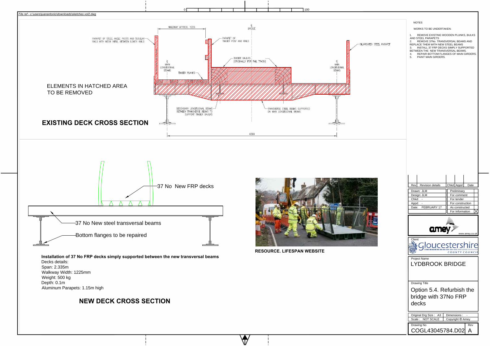
ELEMENTS IN HATCHED AREA
TO BE REMOVED
EXISTING DECK CROSS SECTION
Installation of 37 No FRP decks simply supported between the new transversal beams
Decks details:
Span: 2.335m
Walkway Width: 1225mm
Weight: 500 kg
Depth: 0.1m
Aluminum Parapets: 1.15m high
37 No New steel transversal beams
Bottom flanges to be repaired
37 No New FRP decks
RESOURCE. LIFESPAN WEBSITE
NEW DECK CROSS SECTION
File ref - c:\users\juanantonio\downloads\sketches vol2.dwg
0 100
Drawing No
Project Name
Drawing Title
Original Drg Size :
Scale :
Client
Dimensions :A3
Rev
Revision details
Date:
Drawn:
Chkd:
Appd:
Design:
Rev
As constructed
For construction
For tender
For comment
Chkd Appd Date
Preliminary
c
Copyright Amey
www.amey.co.uk
JLM
JLM
-
-
FEBRUARY 17
For Information
LYDBROOK BRIDGE
Option 5.4. Refurbish the
bridge with 37No FRP
decks
NOT SCALE
-
COGL43045784.D02 A
NOTES
WORKS TO BE UNDERTAKEN:
1. REMOVE EXISTING WOODEN PLUNKS, BULKS
AND STEEL PARAPETS
2. REMOVE 37No. TRANSVERSAL BEAMS AND
REPLACE THEM WITH NEW STEEL BEAMS
3. INSTALL 37 FRP DECKS SIMPLY SUPPORTED
BETWEEN THE NEW TRANSVERSAL BEAMS.
4. REPAIR BOTTOM FLANGES OF MAIN GIRDERS.
5. PAINT MAIN GIRDERS.

REMOVE THE WHOLE EXISTING DECKING INCLUDING MAIN
LONGITUDINAL BEAMS
TRANSVERSAL BEAMS BETWEEN PIERS TO REMAIN.
EXISTING DECK CROSS SECTION
New transversal beams suitable
to carry out new FRP decks
8 No NEW FRP DECKS
Remove transversal beams: Weight 500kg. Length:5m Depth: 425mm
New decks (10m span): Weight: 2100 Kg. Width: 1250mm Depth: 300mm
New deck middle span (16.5m span): Weight: 3400 kg. Width: 1250mm Depth: 300mm
8 No New FRP decks
RESOURCE. LIFESPAN WEBSITE
NEW DECK CROSS SECTION
File ref - c:\users\juanantonio\downloads\sketches vol2.dwg
0 100
Drawing No
Project Name
Drawing Title
Original Drg Size :
Scale :
Client
Dimensions :A3
Rev
Revision details
Date:
Drawn:
Chkd:
Appd:
Design:
Rev
As constructed
For construction
For tender
For comment
Chkd Appd Date
Preliminary
c
Copyright Amey
www.amey.co.uk
JLM
JLM
-
-
FEBRUARY 17
For Information
LYDBROOK BRIDGE
Option 5.4. Refurbish the
bridge with 8No FRP
decks.
NOT SCALE
-
COGL43045784.D03 A
NOTES
WORKS TO BE UNDERTAKEN:
1. REMOVE PARAPETS, TIMBER PLUNKS AND
BULKS.
2. REMOVE 37No TRANSVERSAL BEAMS.
3. REMOVE MAIN LONGITUDINAL BEAMS.
4. INSTALL TRANSVERSAL BEAMS SPANNING
BETWEEN PIERS TO RECEIVE NEW DECKS.
5. INSTALL NEW FRP DECKS SPANNING
BETWEEN PIERS.

Doc. Ref.: COGL43045784 Rev. D Issued August 2017
ANNEX C. PHOTOGRAPHS
Picture 10 Eastern Elevation
Picture 11 View under deck

Project Name Lydbrook Railway Bridge
Document Title Feasibility study
Doc. Ref.:COGL43045784 Rev. D Issued August 2017
Picture 12. Northern Abutment
Picture 13. Vehicle Track at southern end

Project Name Lydbrook Railway Bridge
Document Title Feasibility study
Doc. Ref.:COGL43045784 Rev. D Issued August 2017
Picture 14. Walk way
Picture 15. Deck

Project Name Lydbrook Railway Bridge
Document Title Feasibility study
Doc. Ref.:COGL43045784 Rev. D Issued August 2017
Picture 16. Main girder
Picture 17. Jack rusting in main girders
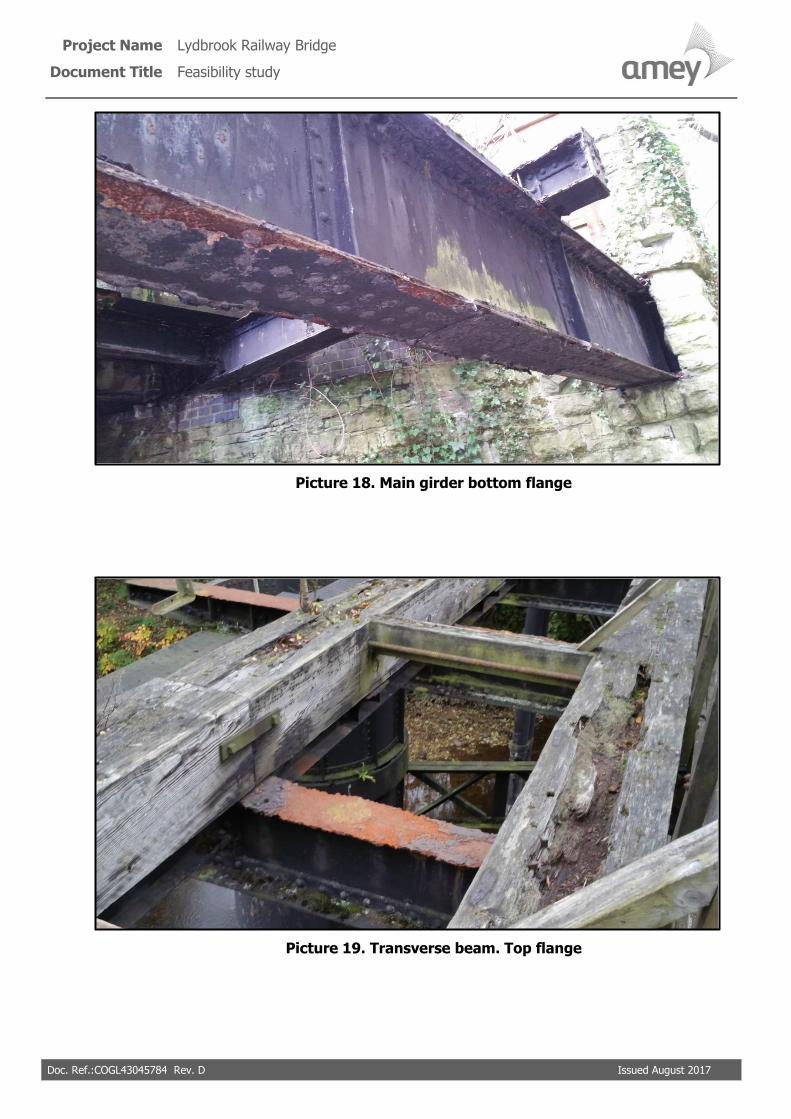
Project Name Lydbrook Railway Bridge
Document Title Feasibility study
Doc. Ref.:COGL43045784 Rev. D Issued August 2017
Picture 18. Main girder bottom flange
Picture 19. Transverse beam. Top flange

Project Name Lydbrook Railway Bridge
Document Title Feasibility study
Doc. Ref.:COGL43045784 Rev. D Issued August 2017
Picture 20. Pier 2
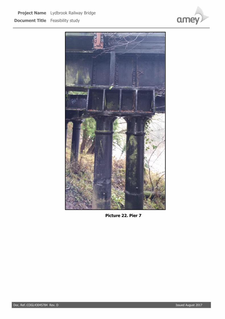
Project Name Lydbrook Railway Bridge
Document Title Feasibility study
Doc. Ref.:COGL43045784 Rev. D Issued August 2017
Picture 22. Pier 7

Project Name Lydbrook Railway Bridge
Document Title Feasibility study
Doc. Ref.:COGL43045784 Rev. D Issued August 2017
Picture 23. Caisson

Project Name Lydbrook Railway Bridge
Document Title Feasibility study
Doc. Ref.:COGL43045784 Rev. D Issued August 2017
Picture 24. Main girders and caisson
Picture 25. Railing at eastern side

Project Name Lydbrook Railway Bridge
Document Title Feasibility study
Doc. Ref.:COGL43045784 Rev. D Issued August 2017
Picture 26. Access to bridge
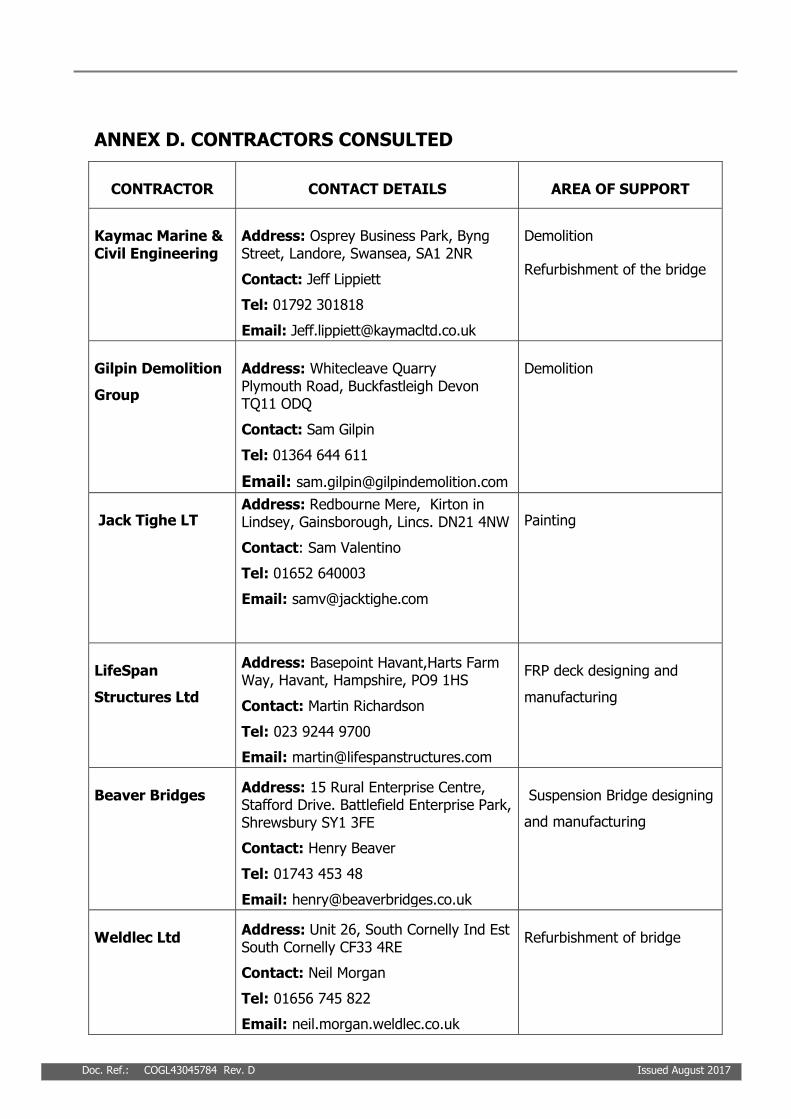
Doc. Ref.: COGL43045784 Rev. D Issued August 2017
ANNEX D. CONTRACTORS CONSULTED
CONTRACTOR CONTACT DETAILS AREA OF SUPPORT
Kaymac Marine & Civil Engineering
Address: Osprey Business Park, Byng Street, Landore, Swansea, SA1 2NR
Contact: Jeff Lippiett
Tel: 01792 301818
Email: [email protected]
Demolition
Refurbishment of the bridge
Gilpin Demolition
Group
Address: Whitecleave Quarry Plymouth Road, Buckfastleigh Devon TQ11 ODQ
Contact: Sam Gilpin
Tel: 01364 644 611
Email: [email protected]
Demolition
Jack Tighe LT Address: Redbourne Mere, Kirton in Lindsey, Gainsborough, Lincs. DN21 4NW
Contact: Sam Valentino
Tel: 01652 640003
Email: [email protected]
Painting
LifeSpan
Structures Ltd
Address: Basepoint Havant,Harts Farm Way, Havant, Hampshire, PO9 1HS
Contact: Martin Richardson
Tel: 023 9244 9700
Email: [email protected]
FRP deck designing and
manufacturing
Beaver Bridges Address: 15 Rural Enterprise Centre, Stafford Drive. Battlefield Enterprise Park, Shrewsbury SY1 3FE
Contact: Henry Beaver
Tel: 01743 453 48
Email: [email protected]
Suspension Bridge designing
and manufacturing
Weldlec Ltd Address: Unit 26, South Cornelly Ind Est South Cornelly CF33 4RE
Contact: Neil Morgan
Tel: 01656 745 822
Email: neil.morgan.weldlec.co.uk
Refurbishment of bridge

Project Name Lydbrook Railway Bridge
Document Title Feasibility study
Doc. Ref.:COGL43045784 Rev. D Issued August 2017
CONTRACTOR CONTACT DETAILS AREA OF SUPPORT
Dorothea
Restoration
Address: Unit 4, William Street, St Phillips, Bristol BS2 ORG
Contact: John Wallis
Tel: 0845 4780773
Email: [email protected]
Repairing works of wrought
iron girders.
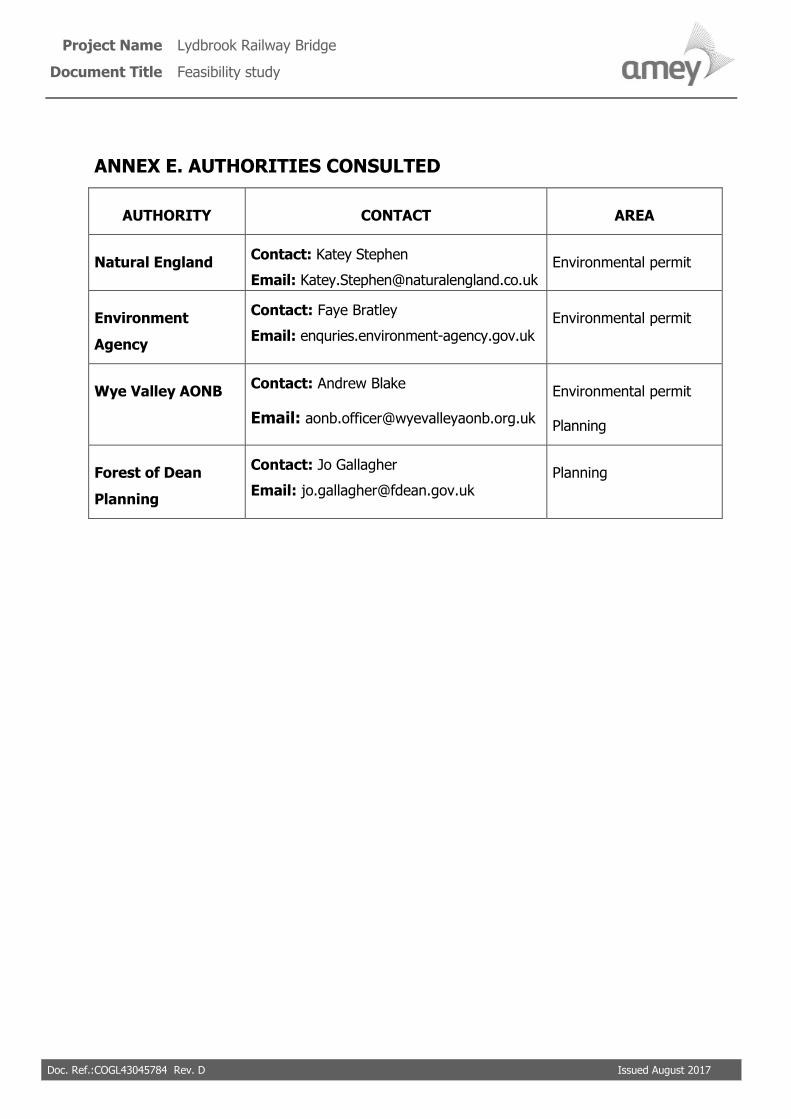
Project Name Lydbrook Railway Bridge
Document Title Feasibility study
Doc. Ref.:COGL43045784 Rev. D Issued August 2017
ANNEX E. AUTHORITIES CONSULTED
AUTHORITY CONTACT AREA
Natural England Contact: Katey Stephen
Email: [email protected] Environmental permit
Environment
Agency
Contact: Faye Bratley
Email: enquries.environment-agency.gov.uk Environmental permit
Wye Valley AONB Contact: Andrew Blake
Email: [email protected]
Environmental permit
Planning
Forest of Dean
Planning
Contact: Jo Gallagher
Email: [email protected] Planning