bacview manual software version 3.06 … · bacview manual . software version 3.06 . 641-k31 ....
TRANSCRIPT
1
BACVIEW MANUAL Software Version 3.06
641-K31
INSTALLATION AND OPERATION MANUAL

2
BACVIEW INSTALLATION AND OPERATION IMPORTANT: This manual is for use with controller ZONE I/O 560 FHP part number 641-224 with software version 3.06 on factory installed equipment. See controller label as shown in figure on page 26 to verify correct part number.
Figure 9 - Heating-Cooling Set point....16 BACVIEW INSTALLATION AND OPERATION .............................................. 2 Tuning parameters ....................................17
Figure 10 - Tuning Parameters .............17 The BACview Interface ............................... 3 Figure 1 – BACview – 641-231............. 3 UPM Faults Screens......................................18
BACview screens....................................... 4 Schedule Screens ..........................................19 Alarm ......................................................... 4 Daily Schedule ..........................................19 Clockset...................................................... 4 Holiday Schedule ......................................19 Keypad ....................................................... 4 Override Schedule.....................................19 BACnet®.................................................... 4 Modifying the Schedule............................20 Comm......................................................... 4 Figure 15 - Daily Schedule ...................20
Figure 2 – BACview Home Screen........ 5 Help Screens .................................................20 Symbols that may appear in the Display.... 5 Figure 17 - Help Screen ........................21
Changing the Password.............................21 Using the BACview..................................... 6 How to Activate the BACview .................. 6 Figure 18 - User password ....................21 How to Activate the BACview .................. 6 Keypad Configuration...................................21 To navigate................................................. 6 Figure 19 - Key pad Configuration.......21
Figure 3 - Arrow keys ............................ 6 Stand by Screen.............................................21 Changing a point value............................... 6 Figure 20 - Stand by screen ..................22 Using Hotkeys............................................ 7 BACnet® Screen ..........................................22
Table 1 – Standard Hotkeys ................... 8 Set Time Screen ............................................22 Muting Alarms ........................................... 8 Figure 21 - Set Time .............................22 Logging in to the BACview ....................... 8 Alarm Screen ................................................23
Table 2 – Screens’ access levels ............ 9 Figure 23 - Alarms screen.....................23 Navigating the BACview screens ............ 10 Overrides Screen...........................................23 HOME...................................................... 10 Figure 24 - Override/Checkout .............24
Figure 4 – HOME screen – Soft keys . 10 Calibration Screen.........................................25 Unit Operation screen .............................. 11 Figure 25 – Calibration .........................25
Figure 5 – Unit operation screen.......... 11 The RS-Pro Sensor interface ....................26 Temperature screen .................................. 12 ICONS.......................................................26 Humidity Control ..................................... 13 BUTTONS ................................................26
Figure 11 - Humidity Screen................ 13 DDC – ZONE I/O 560 ..................................28 Figure 12 – Unit operation Reheat ....... 14 NOTES..........................................................29
Fan screen ................................................ 15 Heating and Cooling screen ..................... 15 Heating and Cooling screen ..................... 16
Figure 8 - Heating- Cooling Screen ..... 16
TABLE OF CONTENTS

The BACview Interface
The BACview module (as shown in figure 1) is a combination keypad/display unit that attaches to a control module to let you view and change property values and the controller’s real time clock in application where a system server is not available.
Figure 1 – BACview – 641-231 The contrast of the LCD display can be adjusted by using a screw diver and turning the contrast screw counterclockwise or clockwise, see figure 1 to locate this feature on the BACview display.
3

BACview screens
Screens can only be accessed if the BACview programmer created links to them, screens shown in this manual have been custom programmed at FHP to support the different Zone controller applications and
this manual shows only the ones for the software version 3.02 for other software versions please visit our website at www.fhp-mfg.com.
Alarm
On this screen the user could see the 100 most recent alarms received by the controller
Clockset
This screen allows the user to set the controller real time clock, however when operating on a network with a server and a gateway the controller will take the time of the gateway and it will always take precedence over the one set by the keypad/display.
Keypad
This screen allows the user or operator to define:
The period of inactivity required before the Display dims out The priority (1-16) the BACview uses to write BACnet® properties. 1 being the highest
priority. 16 is the default.
BACnet®
This screen allows the user to see the controller’s BACnet® name and ID.
Comm
This screen allows the user set the communications protocol and parameters for the port to which a third party device is connected to.
4

Figure 2 – BACview Home Screen
Symbols that may appear in the Display
If the operator selects a screen that requires a password, the LOGIN screen is displayed. How to log in will be covered in detail in the login in section.
Question marks (?????) indicate a programming error that must be fixed by the BACview6 programmer.
Pound signs (#####) indicate that a value has too many digits to display in the existing field.
User may be able to navigate the available screens using pre-programmed “Hotkeys” or “Highlighting Links”.
These terms will be covered in detail in the navigating the BACview screens section.
5

6
Using the BACview
How to Activate the BACview
The BACview screen goes dim after 1 minute of inactivity. Press any key except MUTE or FN, to activate the screen
In the BACview control section, change the number in the Keypad Inactivity timeout field.
How to Activate the BACview
Press any key except MUTE or FN, to activate the screen located above the enter button.
To navigate
To navigate or move within selected screen press the up, down, left and right arrow buttons.
TIP: The inactivity time can be changed by accessing the keypad screen pressing FN + 6.
Figure 3 - Arrow keys
To go to another screen move the cursor to the desired link and press the enter key as shown below:
Changing a point value
Use the navigation keys to highlight the point or property that needs to be changed and press enter.
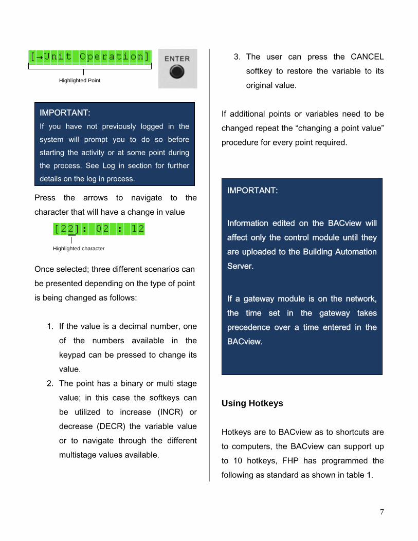
Press the arrows to navigate to the character that will have a change in value
Once selected; three different scenarios can be presented depending on the type of point is being changed as follows:
1. If the value is a decimal number, one of the numbers available in the keypad can be pressed to change its value.
2. The point has a binary or multi stage value; in this case the softkeys can be utilized to increase (INCR) or decrease (DECR) the variable value or to navigate through the different multistage values available.
3. The user can press the CANCEL softkey to restore the variable to its original value.
If additional points or variables need to be changed repeat the “changing a point value” procedure for every point required.
Using Hotkeys
Hotkeys are to BACview as to shortcuts are to computers, the BACview can support up to 10 hotkeys, FHP has programmed the following as standard as shown in table 1.
IMPORTANT:
Information edited on the BACview will affect only the control module until they are uploaded to the Building Automation Server.
If a gateway module is on the network, the time set in the gateway takes precedence over a time entered in the BACview.
Highlighted Point
IMPORTANT: If you have not previously logged in the system will prompt you to do so before starting the activity or at some point during the process. See Log in section for further details on the log in process.
Highlighted character
7
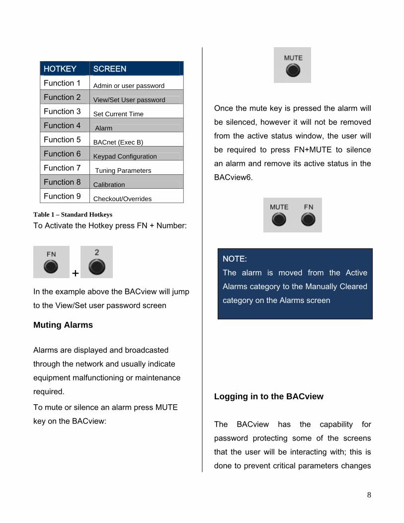
HOTKEY SCREEN
Function 1 Admin or user password
Function 2 View/Set User password
Function 3 Set Current Time
Function 4 Alarm
Function 5 BACnet (Exec B)
Function 6 Keypad Configuration
Function 7 Tuning Parameters
Function 8 Calibration
Function 9 Checkout/Overrides Table 1 – Standard Hotkeys To Activate the Hotkey press FN + Number:
+
In the example above the BACview will jump to the View/Set user password screen
Muting Alarms
Alarms are displayed and broadcasted through the network and usually indicate equipment malfunctioning or maintenance required.
To mute or silence an alarm press MUTE key on the BACview:
Once the mute key is pressed the alarm will be silenced, however it will not be removed from the active status window, the user will be required to press FN+MUTE to silence an alarm and remove its active status in the BACview6.
Logging in to the BACview
The BACview has the capability for password protecting some of the screens that the user will be interacting with; this is done to prevent critical parameters changes
NOTE: The alarm is moved from the Active Alarms category to the Manually Cleared category on the Alarms screen
8

9
Restriction Level Access
None
Anyone can access, but to edit a field in this screen, the operator must log in with either the User or Admin password.
User or Customer An operator logged in with the User or Admin password.
Technician An operator logged in with the Admin password.
by non qualified personnel in a particular unit. If while accessing a particular screen or variable a log in is required the user needs to enter the four (4) digits password FHP has preprogrammed these to be the following:
Technician password: 1111 User/ Customer password: 0000 BACview allows screens to be programmed with different access restrictions or access levels as shown in table 2.
Table 2 – Screens’ access levels
In some cases the screen is not password protected, however some of the parameters or variables within the screen may be, a common indication that the variable or parameter is password protected that the user is prompted to log in to change a particular value.
IMPORTANT: Critical set points such as High/Low cooling and heating limit set points should only be changed by qualified personnel and/or as directed by test and balancing agency.
Navigating the BACview screens
BACview screens can be accessed and navigated using three methods as mentioned in Using the Bacview section. This section uses both concepts combined so that the user is familiar with both as most real applications need the combination of the arrow keys and soft keys methods to access the different screens.
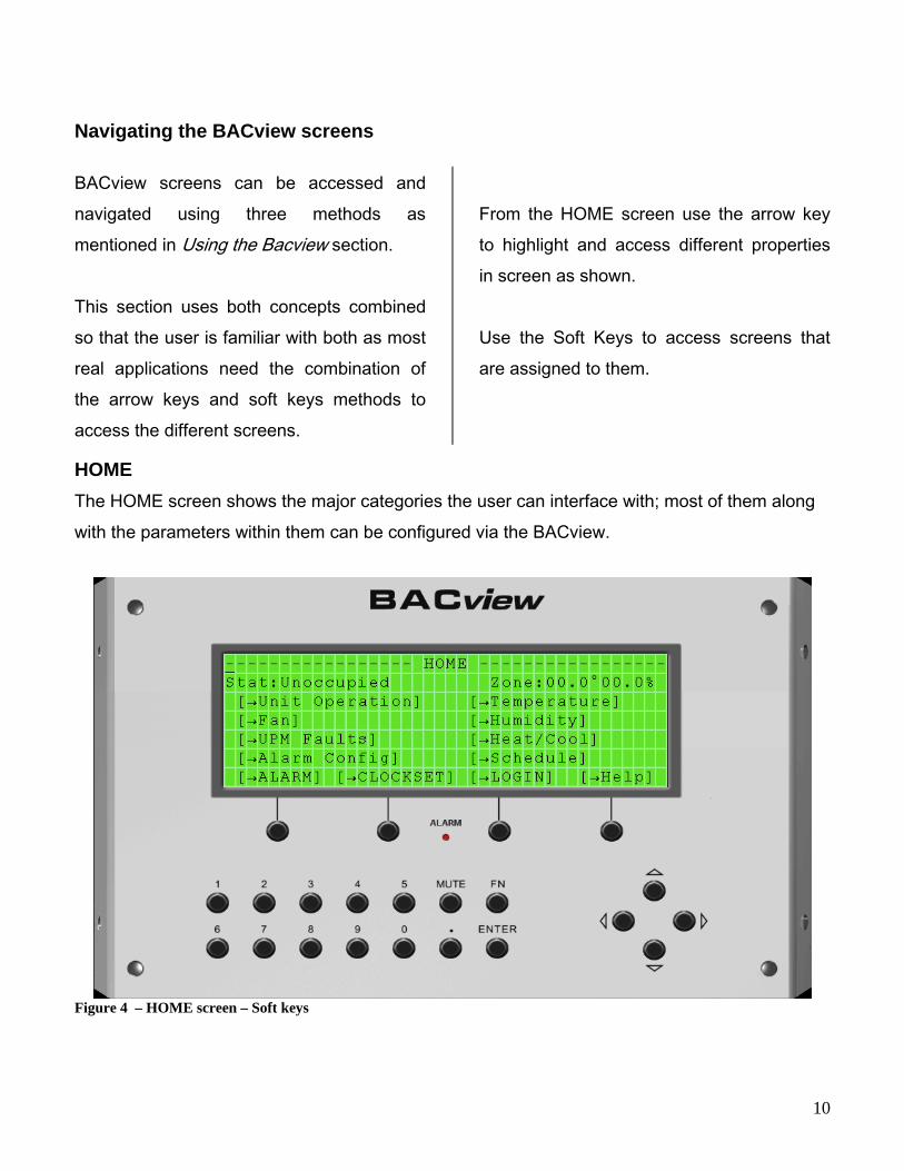
From the HOME screen use the arrow key to highlight and access different properties in screen as shown. Use the Soft Keys to access screens that are assigned to them.
HOME The HOME screen shows the major categories the user can interface with; most of them along with the parameters within them can be configured via the BACview.
Figure 4 – HOME screen – Soft keys
10

Unit Operation screen The unit operation screen can be accessed by selecting its link on the Home screen. Use the navigation keys to scroll down and see all parameters available on this screen. This screen allows the user to select the software mode Keypad_Schedule is the factory default.
User can change this to be:
Manual On BAS Command Digital Enable
Note: The Softkeys will allow the user to access other frames/screens as shown.
Figure 5 – Unit operation screen
11

Temperature screen The Temperature screen can be accessed by selecting its link on the Home screen. Use the navigation keys to scroll down and see all parameters available on this screen. This screen allows the user to see all the current values of the temperature variables From the Temperature screen the user can access the temperature set points values which allow the user to set up the occupied and unoccupied set points to which the unit will operate on the daily basis. The set points can be access via the soft keys as shown on below.
Figure 6 - Temperature screens
IMPORTANT: The user should never overlap the High and Low set points for heating and cooling operation, as this may cause the unit to be trapped in a dead band and will try to cool and heat at the same time. Example: Occupied cooling set point 69 ºF
Occupied heating Set point 71 ºF
IMPORTANT: The user will not be able to change the heating and cooing set points below the high and low limits. In order to change heating and cooling set points below the limits, the limits will have to be changed on the Tuning parameters screen FN + 7.
12

Humidity Control
From the home screen select the Humidity link use the arrow key to highlight and access different properties in screen as shown.
To navigate and or change properties on this screen the user may follow the same steps as illustrated in the changing a value section of this manual.
IMPORTANT: The following screen and all the sub-screens and menus derived from it as shown in this section are only available on units with the Re-Heat option A and software version 3.06.
REMINDER: Only highlighted characters can be changed. Reheat valve is always connected to DO5. Some changes may be restricted to a limited interval or a particular range of negative and positive values
Figure 7 - Humidity Screen
13

Figure 8 – Unit operation Reheat
14

15
Fan screen The Fan screen can be accessed by selecting its link on the Home screen. Use the navigation keys to scroll down and see all parameters available on this screen. This screen allows the user to see all the current values of the fan variables and points. From the Fan screen the user can access the service screen (stpt) on which the fan
runtime hours are displayed this parameter is normally utilized as a remainder for filter change. Once on the Set point screen the user can reset the timer to start a new count after replacing the filter. The stpt can be access via the soft keys as shown on below.
Figure 9 - Fan Screen

Heating and Cooling screen The Heating/Cooling screen can be accessed from the Home screen. As explained in the previous sections the softkeys will allow the user to access other frames/screens by pressing the navigation arrows. Navigate and or change properties on this screen the user may follow the same steps as illustrated in the changing a value section of this manual. From the Heating/ Cooling screen the user can see the actual state of the different points that are involved and needed for the cooling and heating operation respectively as shown in figure 8. The service screen is accessed by pressing “Stpt” the runtime hours and counters for the compressors are displayed as shown in figure 9 and can be reset by navigating selecting and changing the particular value.
Figure 10 - Heating- Cooling Screen
Figure 11 - Heating-Cooling Set point
IMPORTANT: The user will not be able to change the heating and cooing set points below the high and low limits. In order to change heating and cooling set points below the limits, the limits will have to be changed on the Tuning parameters screen.
16

Tuning parameters
Tuning parameters are a very important feature as they provide the high and low limits of the different modes occupied and unoccupied heating and cooling respectively. This can be accessed through the hot keys by pressing:
+ The screen shows the unit heating and cooling percentage demands. Based on values the unit will determine when to initiate a cooling or heating operation. See figure 10 for a Tuning screen snap shot.
Figure 12 - Tuning Parameters
IMPORTANT: The user should never overlap the High and Low limits for heating and cooling operation, as this may cause the unit to be trapped in a dead band and will try to cool and heat at the same time. Example: Occupied cooling Low Limit 69 ºF
Occupied heating Hi Limit 71 ºF
17

UPM Faults Screens
The UPM FAULT screen can be accessed from the Home screen. To navigate on this screen the user may follow the same steps as illustrated in the changing a value section of this manual.
Once an alarm is received via pulse feedback from the UPM board, it is displayed in the screen as shown below. From this screen the user may reset the UPM board after it has enter the lockout mode by navigating to “Reset UPM now?” selecting yes and pressing the enter key.
Figure 13 - UPM Faults Screen
18
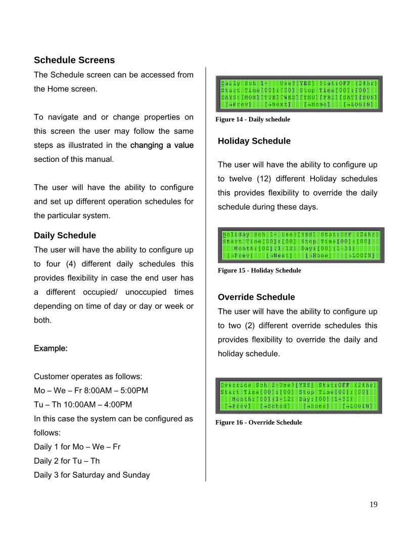
Schedule Screens
The Schedule screen can be accessed from the Home screen. To navigate and or change properties on this screen the user may follow the same steps as illustrated in the changing a value section of this manual. The user will have the ability to configure and set up different operation schedules for the particular system.
Daily Schedule
The user will have the ability to configure up to four (4) different daily schedules this provides flexibility in case the end user has a different occupied/ unoccupied times depending on time of day or day or week or both. Example: Customer operates as follows: Mo – We – Fr 8:00AM – 5:00PM Tu – Th 10:00AM – 4:00PM In this case the system can be configured as follows: Daily 1 for Mo – We – Fr Daily 2 for Tu – Th Daily 3 for Saturday and Sunday
Holiday Schedule
The user will have the ability to configure up to twelve (12) different Holiday schedules this provides flexibility to override the daily schedule during these days.
Override Schedule
The user will have the ability to configure up to two (2) different override schedules this provides flexibility to override the daily and holiday schedule.
Figure 14 - Daily schedule
Figure 15 - Holiday Schedule
Figure 16 - Override Schedule
19
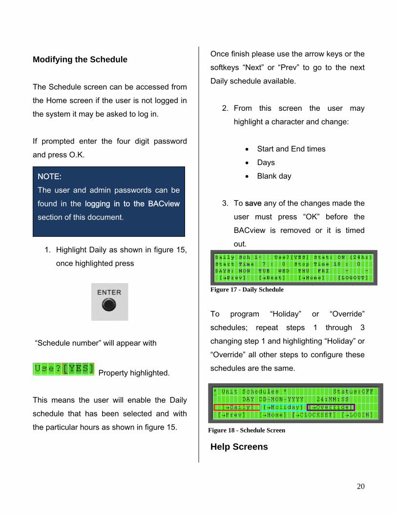
Modifying the Schedule
The Schedule screen can be accessed from the Home screen if the user is not logged in the system it may be asked to log in. If prompted enter the four digit password and press O.K.
1. Highlight Daily as shown in figure 15, once highlighted press
“Schedule number” will appear with
Property highlighted. This means the user will enable the Daily schedule that has been selected and with the particular hours as shown in figure 15.
Once finish please use the arrow keys or the softkeys “Next” or “Prev” to go to the next Daily schedule available.
2. From this screen the user may highlight a character and change:
Start and End times Days Blank day NOTE:
The user and admin passwords can be found in the logging in to the BACview section of this document.
3. To save any of the changes made the
user must press “OK” before the BACview is removed or it is timed out.
Figure 17 - Daily Schedule To program “Holiday” or “Override” schedules; repeat steps 1 through 3 changing step 1 and highlighting “Holiday” or “Override” all other steps to configure these schedules are the same.
Figure 18 - Schedule Screen
Help Screens
20

The Help screen can be accessed from the Home screen. To navigate on this screen the user may follow the same steps as illustrated in the changing a value section of this manual. From the Help screen the user is able to access the software version of the controller to which it is connected, this information will be asked whenever technical support is contacted.
Figure 19 - Help Screen The technical support phone numbers can also be found in this screen as shown in the figure above.
Changing the Password
The user or administrator can change the user password by pressing the soft key “LOGIN”. This screen can also be accessed by pressing:
+
Make sure the new user password is recorded in an accessible place other wise user will have to use the administrator password to reset it and/or retrieve it
Figure 20 - User password
Keypad Configuration
The user or administrator can change the amount of time the Key pad is kept lit by pressing the function key and number six and then changing the number of minutes the key pad is to remain lit.
+
Figure 21 - Key pad Configuration
Stand by Screen
This screen is what will be normally shown in the BACview before any key is pressed.
21
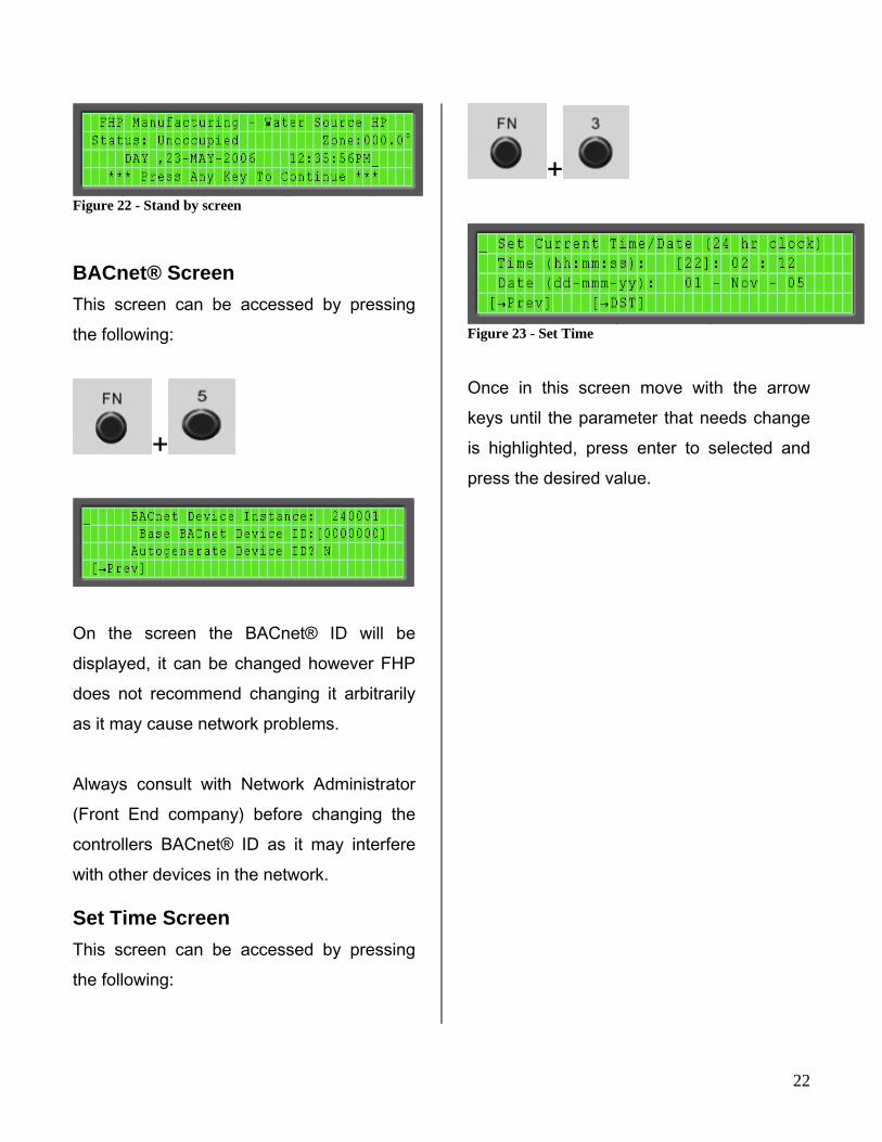
Figure 22 - Stand by screen
BACnet® Screen
This screen can be accessed by pressing the following:
+
On the screen the BACnet® ID will be displayed, it can be changed however FHP does not recommend changing it arbitrarily as it may cause network problems. Always consult with Network Administrator (Front End company) before changing the controllers BACnet® ID as it may interfere with other devices in the network.
Set Time Screen
This screen can be accessed by pressing the following:
+
Figure 23 - Set Time Once in this screen move with the arrow keys until the parameter that needs change is highlighted, press enter to selected and press the desired value.
22

23
Overrides Screen Alarm Screen
This screen can be accessed by pressing the following:
This screen can be accessed by pressing the following:
+ +
The checkout/overrides screen allows the user to start up the unit by overriding its outputs.
The Alarm screen allows the user to up to 100 events starting with the most recent.
It also allows user to see which points have gone into alarm and retuned to normal as well as the ones that have been manually cleared.
The user can also use this screen as test procedure to ensure the low voltage components are working according to the unit wiring diagram.
Figure 36 illustrates the Alarm screen with no alarms registered in the system.
When overriding inputs or outputs the alarm LED of the BACview will lit up indicating an override condition, in addition, if the unit has the RS-Pro sensor connected to the Rnet port it will display the bell that indicates alarm condition and show error code 20 when pressing the info button. (See RS-pro sensor section for additional information)
Figure 24 - Alarms screen

Figure 25 - Override/Checkout
24
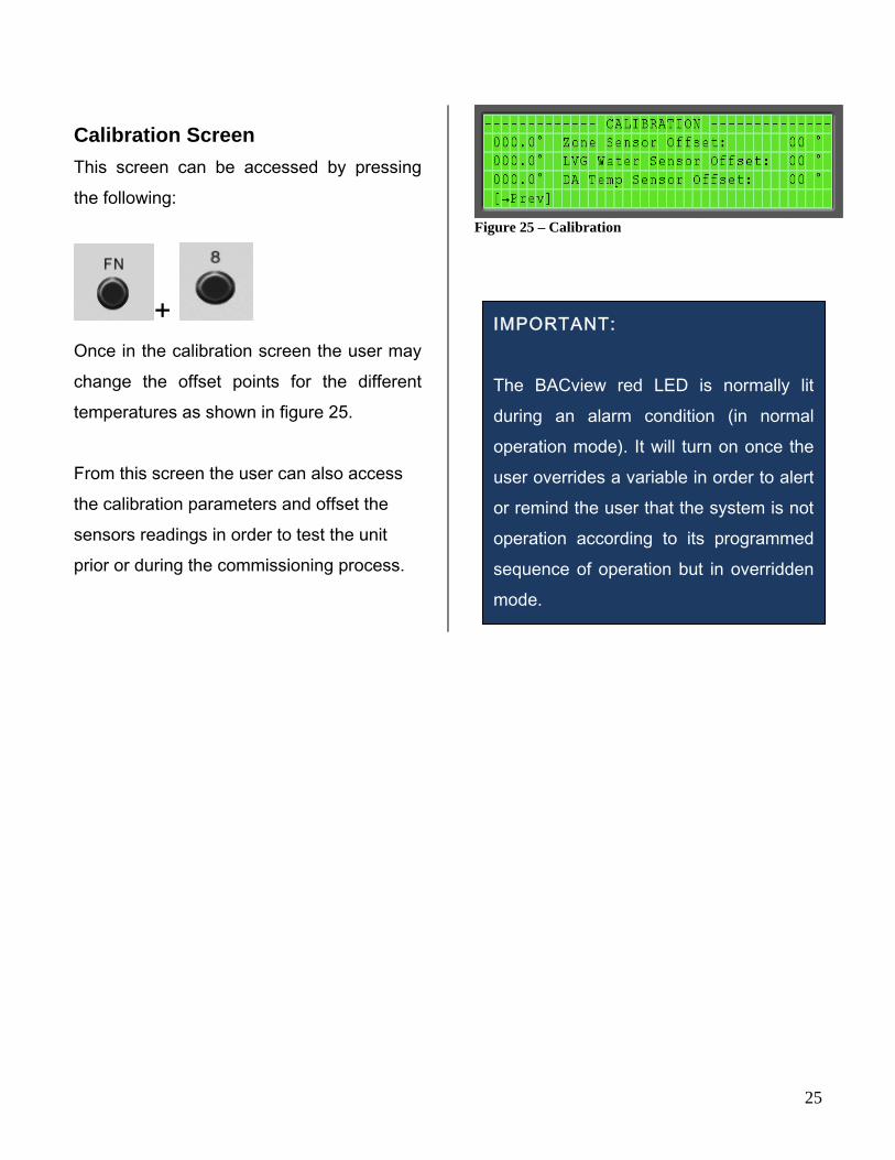
Calibration Screen
This screen can be accessed by pressing the following:
+
Once in the calibration screen the user may change the offset points for the different temperatures as shown in figure 25. From this screen the user can also access the calibration parameters and offset the sensors readings in order to test the unit prior or during the commissioning process.
Figure 25 – Calibration
IMPORTANT: The BACview red LED is normally lit during an alarm condition (in normal operation mode). It will turn on once the user overrides a variable in order to alert or remind the user that the system is not operation according to its programmed sequence of operation but in overridden mode.
25
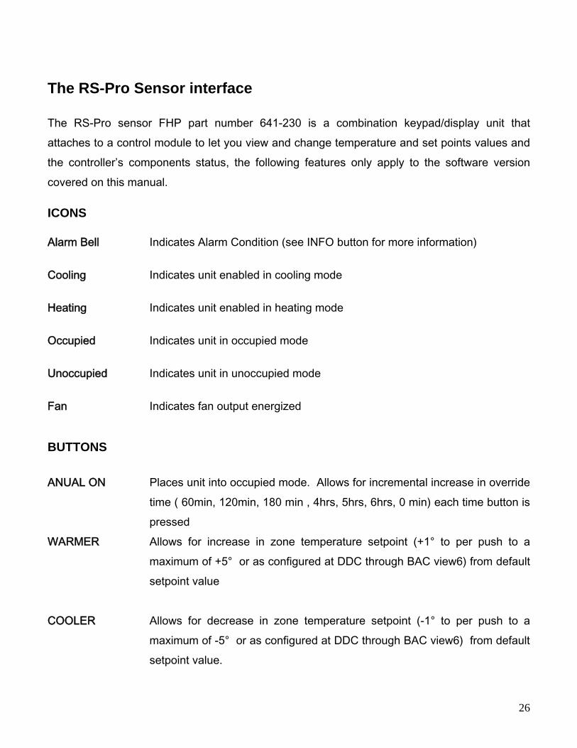
The RS-Pro Sensor interface
The RS-Pro sensor FHP part number 641-230 is a combination keypad/display unit that attaches to a control module to let you view and change temperature and set points values and the controller’s components status, the following features only apply to the software version covered on this manual. ICONS
Alarm Bell Indicates Alarm Condition (see INFO button for more information)
Cooling Indicates unit enabled in cooling mode
Heating Indicates unit enabled in heating mode
Occupied Indicates unit in occupied mode
Unoccupied Indicates unit in unoccupied mode
Fan Indicates fan output energized
BUTTONS
ANUAL ON Places unit into occupied mode. Allows for incremental increase in override
time ( 60min, 120min, 180 min , 4hrs, 5hrs, 6hrs, 0 min) each time button is pressed
WARMER Allows for increase in zone temperature setpoint (+1° to per push to a maximum of +5° or as configured at DDC through BAC view6) from default setpoint value
COOLER Allows for decrease in zone temperature setpoint (-1° to per push to a
maximum of -5° or as configured at DDC through BAC view6) from default setpoint value.
26
27
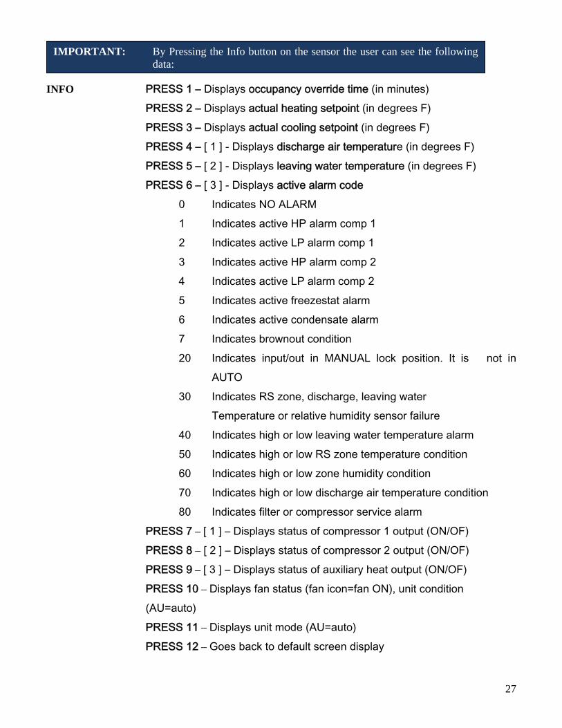
IMPORTANT: By Pressing the Info button on the sensor the user can see the following data:
INFO PRESS 1 – Displays occupancy override time (in minutes) PRESS 2 – Displays actual heating setpoint (in degrees F)
PRESS 3 – Displays actual cooling setpoint (in degrees F) PRESS 4 – [ 1 ] - Displays discharge air temperature (in degrees F) PRESS 5 – [ 2 ] - Displays leaving water temperature (in degrees F) PRESS 6 – [ 3 ] - Displays active alarm code 0 Indicates NO ALARM 1 Indicates active HP alarm comp 1 2 Indicates active LP alarm comp 1 3 Indicates active HP alarm comp 2 4 Indicates active LP alarm comp 2 5 Indicates active freezestat alarm
6 Indicates active condensate alarm 7 Indicates brownout condition
20 Indicates input/out in MANUAL lock position. It is not in AUTO
30 Indicates RS zone, discharge, leaving water Temperature or relative humidity sensor failure
40 Indicates high or low leaving water temperature alarm 50 Indicates high or low RS zone temperature condition 60 Indicates high or low zone humidity condition 70 Indicates high or low discharge air temperature condition 80 Indicates filter or compressor service alarm
PRESS 7 – [ 1 ] – Displays status of compressor 1 output (ON/OF) PRESS 8 – [ 2 ] – Displays status of compressor 2 output (ON/OF) PRESS 9 – [ 3 ] – Displays status of auxiliary heat output (ON/OF) PRESS 10 – Displays fan status (fan icon=fan ON), unit condition (AU=auto) PRESS 11 – Displays unit mode (AU=auto) PRESS 12 – Goes back to default screen display

DDC – ZONE I/O 560
FHP ORDER # LINE # - MODEL #
FHP PART # SW VERSION
28

NOTES
29

30
601 N.W. 65th Court, Ft. Lauderdale, FL 33309 Phone: 954-776-5471 Fax: 954-776-5529 www.fhp-mfg.com 970-434 REV. 9-10