balancing of reciprocating masses - weeblyramadossegsp.weebly.com/uploads/9/3/7/8/93786092/u… ·...
TRANSCRIPT

VTU EDUSAT PROGRAMME-17
DYNAMICS OF MACHINES
Subject Code -10 ME 54
BALANCING OF
RECIPROCATING MASSES
BALANCING
OFRECIPROCATING MASSES
n
SLIDER CRANK MECHANISM:
PRIMARY AND SECONDARYACCELERATING FORCE:
Acceleration of the reciprocating mass of a slider-crank mechanism is given by,
ap Acceleration of piston
cos 2 r2
cos (1)
Where nl
r
And, the force required to accelerate the mass ‘m’ is
ni
2
mr2 cos mr2 cos2 (2)
n
cos2F mr cos
Notes Compiled by:
VIJAYAVITHAL BONGALE
ASSOCIATE PROFESSOR
DEPARTMENT OF MECHANICAL ENGINEERING
MALNAD COLLEGE OF ENGINEERING
HASSAN -573 202. KARNATAKA
Mobile:9448821954E-mail:[email protected]
DYNAMICS OF MACHINES 1 VIJAYAVITHAL BONGALE

VTU EDUSAT PROGRAMME-17
The first term of the equation (2) , i.e. mr2 cos is called primary accelerating
nforce the second term mr
2 cos2is called the secondary accelerating force.
Maximum value of primary accelerating force is mr2
And Maximum value of secondary accelerating force isn
mr2
Generally, ‘n’ value is much greater than one; the secondary force is small compared to
primary force and can be safely neglected for slow speed engines.
In Fig (a), the inertia force due to primary accelerating force is shown.
DYNAMICS OF MACHINES 2 VIJAYAVITHAL BONGALE

DYNAMICS OF MACHINES 3 VIJAYAVITHAL BONGALE
VTU EDUSAT PROGRAMME-17
In Fig (b), the forces acting on the engine frame due to inertia force are shown.
At ‘O’ the force exerted by the crankshaft on the main bearings has two components,
horizontal F21
h vF21and vertical .
hF21 is an horizontal force, which is an unbalanced shaking force.
vF21 and F v
41 balance each other but form an unbalanced shaking couple.
The shaking force
The magnitude and direction of these unbalanced force and couple go on changing with
angle θ. The shaking force produces linear vibrations of the frame in horizontal direction,
whereas the shaking couple produces an oscillating vibration.hF21 is the only unbalanced force which may hamper the smooth
running of the engine and effort is made to balance the same.
However it is not at all possible to balance it completely and only some modifications can
be carried out.
BALANCING OF THE SHAKING FORCE:
Shaking force is being balanced by adding a rotating counter mass at radius ‘r’ directly
opposite the crank. This provides only a partial balance. This counter mass is in addition
to the mass used to balance the rotating unbalance due to the mass at the crank pin. This
is shown in figure (c).

VTU EDUSAT PROGRAMME-17
The horizontal component of the centrifugal force due to the balancing mass is
mr 2 cos and this is in the line of stroke. This component neutralizes the unbalanced
reciprocating force. But the rotating mass also has a component mr2 sin
perpendicular to the line of stroke which remains unbalanced. The unbalanced force is
zero at θ = 00 or 1800 and maximum at the middle of the stroke i.e. θ = 900. The
magnitude or the maximum value of the unbalanced force remains the same i.e. equal to
mr 2. Thus instead of sliding to and fro on its mounting, the mechanism tends to
jump up and down.
2To minimize the effect of the unbalance force a compromise is, usually made, is of the
3
1 3reciprocating mass is balanced or a value between to .
2 4
If ‘c’ is the fraction of the reciprocating mass, then
The primary force balanced by the mass cmrω 2 cosθ
and
The primary force unbalanced by the mass (1c) mrω 2 cos θ
Vertical component of centrifuga l force which remains unbalanced
c mr ω 2 sinθ
In reciprocating engines, unbalance forces in the direction of the line of stroke are more
dangerous than the forces perpendicular to the line of stroke.
Resultant unbalanced force at any instant
(1 c)mrω 2 cosθ2 cmrω 2 sinθ2
1
2
DYNAMICS OF MACHINES 4 VIJAYAVITHAL BONGALE
The resultant unbalanced force is minimum when, c
This method is just equivalent to as if a revolving mass at the crankpin is completely
balanced by providing a counter mass at the same radius diametrically opposite to the
crank. Thus if mP is the mass at the crankpin and ‘c’ is the fraction of the reciprocating
mass ‘m’ to be balanced , the mass at the crankpin may be considered as cmmP
which is to be completely balanced.

VTU EDUSAT PROGRAMME-17
3P c
m 40 kg, c 2
, r 350 mm
Problem 1:
A single –cylinder reciprocating engine has a reciprocating mass of 60 kg. The crank
rotates at 60 rpm and the stroke is 320 mm. The mass of the revolving parts at 160 mm
radius is 40 kg. If two-thirds of the reciprocating parts and the whole of the revolving
parts are to be balanced, determine the, (i) balance mass required at a radius of 350 mm
and (ii) unbalanced force when the crank has turned 500 from the top-dead centre.
Solution:
Given : m mass of the reciprocating parts 60 kg
N 60 rpm, L length of thestroke 320 mm
(i) Balance mass required at a radius of 350 mm
We have,
2 2r
L320
160 mm
ω 2πN
2πx60
2π rad/s60 60
3P
M c m m 2
x60 40 80 kg
Mass to be balanced at thecrankpin M
and
350
therefore m
c
rc
c c c
i.e. m 80 x160
36.57 kg
Mr
m r Mr
3
DYNAMICS OF MACHINES 5 VIJAYAVITHAL BONGALE
22
02
209.9 N
3 2π cos50
2 x60 x 0.16x2π2 sin50 0
2 1 x 60 x0.16x
(ii) Unbalanced force when the crank has turned 500 from the top-dead centre.
Unbalanced force at θ50 0
1 cmrω 2 cosθ2 cmrω 2 sinθ2

VTU EDUSAT PROGRAMME-17
c
P
c 60 % , r 320 mm
m 30 kg , N 150 rpm, L length of the stroke 350 mm
Problem 2:
The following data relate to a single cylinder reciprocating engine:
Mass of reciprocating parts = 40 kg
Mass of revolving parts = 30 kg at crank radius
Speed = 150 rpm, Stroke = 350 mm.
If 60 % of the reciprocating parts and all the revolving parts are to be balanced, determine
the,
(i) balance mass required at a radius of 320 mm and (ii) unbalanced force when the crank
has turned 450 from the top-dead centre.
Solution:
Given : m mass of the reciprocating parts 40 kg
(i) Balance mass required at a radius of 350 mm
We have,
2 2r
L
350 175 mm
ω 2πN
2πx150
15.7 rad/s60 60
Mass to be balanced at the crank pin M
M c m mP 0.60 x 40 30 54 kg
and
320c
rc
i.e. m 54 x175
29.53 kg
Mr
m c rc Mr therefore m c
(ii) Unbalanced force when the crank has turned 450 from the top-dead centre.
Unbalanced force at θ 45 0
1 cmrω 2 cosθ2 cmrω 2 sinθ2
1 0.60x 40 x 0.175x 15.72 cos 45 0 2 0.60 x 40 x 0.175x15.72 sin45 0 2
880.7 N
DYNAMICS OF MACHINES 6 VIJAYAVITHAL BONGALE

VTU EDUSAT PROGRAMME-17
SECONDARY BALANCING:
1n
times the
Secondary acceleration force is equal to mr2 cos2 (1)
n
Its frequency is twice that of the primary force and the magnitude
magnitude of the primary force.
The secondary force is also equal to mr(2)2 cos2 (2)
4n
Consider, two cranks of an engine, one actual one and the other imaginary with the
following specifications.
Thus, when the actual crank has turned through an angle t , the imaginary crank
would have turned an angle 2 2 t
DYNAMICS OF MACHINES 7 VIJAYAVITHAL BONGALE
Actual Imaginary
Angular velocity 2Length of crank r r
4nMass at the crank pin m m

VTU EDUSAT PROGRAMME-17
4nCentrifugal force induced in the imaginary crank = mr2ω
2
4nComponent of this force along the line of stroke is = mr2ω
cos2θ2
Thus the effect of the secondary force is equivalent to an imaginary crank of lengthr
4n
DYNAMICS OF MACHINES 8 VIJAYAVITHAL BONGALE
rotating at double the angular velocity, i.e. twice of the engine speed. The imaginary
crank coincides with the actual at inner top-dead centre. At other times, it makes an angle
with the line of stroke equal to twice that of the engine crank.
The secondary couple about a reference plane is given by the multiplication of the
secondary force with the distance ‘ l ’ of the plane from the reference plane.
COMPLETE BALANCING OF RECIPROCATING PARTS
Conditions to be fulfilled:
1. Primary forces must balance i.e., primary force polygon is enclosed.
2. Primary couples must balance i.e., primary couple polygon is enclosed.
3. Secondary forces must balance i.e., secondary force polygon is enclosed.
4. Secondary couples must balance i.e., secondary couple polygon is enclosed.
Usually, it is not possible to satisfy all the above conditions fully for multi-cylinder
engine. Mostly some unbalanced force or couple would exist in the reciprocating engines.
BALANCING OF INLINE ENGINES:
An in-line engine is one wherein all the cylinders are arranged in a single line, one behind
the other. Many of the passenger cars such as Maruti 800, Zen, Santro, Honda-city,
Honda CR-V, Toyota corolla are the examples having four cinder in-line engines.
In a reciprocating engine, the reciprocating mass is transferred to the crankpin; the axial
component of the resulting centrifugal force parallel to the axis of the cylinder is the
primary unbalanced force.
Consider a shaft consisting of three equal cranks asymmetrically spaced. The crankpins
carry equivalent of three unequal reciprocating masses, then

VTU EDUSAT PROGRAMME-17
Primary force ∑m rω 2 cos θ (1)
Primary couple ∑m rω 2 l cos θ (2)
∑ cos 2θ (3)4n
2ωSecondary force m r
2
∑ l cos 2θ4n
2ωAnd Secondary couple m r
ω 2
2
∑m rn
l cos 2θ (4)
GRAPHICAL SOLUTION:
To solve the above equations graphically, first draw the2
∑m r cos θ polygon ( is
common to all forces). Then the axial component of the resultant forces (Fr cos)
multiplied by 2 provides the primary unbalanced force on the system at that moment.
This unbalanced force is zero when 900 and a maximum when 00
.
DYNAMICS OF MACHINES 9 VIJAYAVITHAL BONGALE

VTU EDUSAT PROGRAMME-17
If the force polygon encloses, the resultant as well as the axial component will always be
zero and the system will be in primary balance.Then,
∑ FP h 0 and ∑ FP V 0
To find the secondary unbalance force, first find the positions of the imaginary secondary
cranks. Then transfer the reciprocating masses and multiply the same by4n
22or
2
nto get the secondary force.
In the same way primary and secondary couple ( m r l ) polygon can be drawn for
primary and secondary couples.
Case 1:
IN-LINE TWO-CYLINDER ENGINE
Two-cylinder engine, cranks are 1800 apart and have equal reciprocating masses.
DYNAMICS OF MACHINES 10 VIJAYAVITHAL BONGALE

VTU EDUSAT PROGRAMME-17
Taking a plane through the centre line as the reference plane,
Primary force m rω 2 cos θ cos (180 θ) 0
2 2
2
l l cosθ cos(180 θ) m rω2 l cosθPrimary couple m rω
Maximum values are m rω2 l at θ0 0 and180 0
n n
2 2
Secondary force m rω cos 2θ cos(360 2θ) 2m rω
cos2θ
nMaximum values are 2m rω
2 0 0 0 0
when 2θ 0 , 180 , 360 and 540
or θ 0 0 , 90 0 ,180 0 and 270 0
DYNAMICS OF MACHINES 11 VIJAYAVITHAL BONGALE

VTU EDUSAT PROGRAMME-17
n 2
2
2
l l cos2θ cos(360 2θ ) 0Secondary couple
m rω
ANALYTICAL METHOD OF FINDING PRIMARY FORCES AND COUPLES
First the positions of the cranks have to be taken in terms of θ 0
The maximum values of these forces and couples vary instant to instant and are
equal to the values as given by the equivalent rotating masses at the crank pin.
If a particular position of the crank shaft is considered, the above expressions may not
give the maximum values.
For example, the maximum value of primary couple is m rω2 l and this value is
obtained at crank positions 00 and 1800. However, if the crank positions are assumed
at 900 and 2700, the values obtained will be zero.
If any particular position of the crank shaft is considered, then both X and Y
components of the force and couple can be taken to find the maximum values.
For example, if the crank positions considered as 1200 and 3000, the primary couple
can be obtained as
22
0 002
1
m r ω 2 l2
180 120
l l cos 120 cos m r ωX component
sin 0 002
3
mrω 2 l2
2
l180 120
2
l Y component mrω sin120
Therefore,3
DYNAMICS OF MACHINES 12 VIJAYAVITHAL BONGALE
2
1 22
2
2
mrω 2 l
Primary couple mrω l 2
mrω l
Case 2:
IN-LINE FOUR-CYLINDER FOUR-STROKE ENGINE

DYNAMICS OF MACHINES 13 VIJAYAVITHAL BONGALE
VTU EDUSAT PROGRAMME-17
This engine has tow outer as well as inner cranks (throws) in line. The inner throws are at
1800 to the outer throws. Thus the angular positions for the cranks are θ 0 for the first,
180 0 θ 0 for the second, 180 0 θ 0 for the third and θ 0 for the fourth.

VTU EDUSAT PROGRAMME-17
FINDING PRIMARY FORCES, PRIMARY COUPLES, SECONDARY FORCES
AND SECONDARY COUPLES:
Choose a plane passing through the middle bearing about which the arrangement is
symmetrical as the reference plane.
Primary force m rω 2 cosθ cos (180 0 θ) cos (180 0 θ) cos θ 0
3l
2
0
0
2 2
l cos (180 θ) cosθ
3lcosθ
lcos (180 0 θ)
Primary couple m rω 2 2
cos2θn
n
2
0
0
4m rω
2
cos (360 2θ) cos 2θ
cos 2θ cos(360 2θ) Secondary force
m rω
n
m rω 2
at 2θ 0 0 ,18 0 0 ,360 0 and 54 0 0 or
θ 0 0 ,9 0 0 ,180 0 and 270 0
Maximum value
2
DYNAMICS OF MACHINES 14 VIJAYAVITHAL BONGALE
n 0
0
22
2 2
l 3l cos(360 2θ) cos2θ
3lcos2θ
lcos(360 0 2θ)
Secondary couple m rω
Thus the engine is not balanced in secondary forces.

VTU EDUSAT PROGRAMME-17
Problem 1:
A four-cylinder oil engine is in complete primary balance. The arrangement of the
reciprocating masses in different planes is as shown in figure. The stroke of each piston is
2 r mm. Determine the reciprocating mass of the cylinder 2 and the relative crank
position.
Solution:
Given :
m1 380 kg, m2 ? , m 3 590 kg, m 4 480 kg
crank length L2r
r2 2
DYNAMICS OF MACHINES 15 VIJAYAVITHAL BONGALE
PlaneMass (m)
kg
Radius (r)
m
Cent.
Force/ω2
(m r )kg m
Distance
from Ref
plane ‘2’
m
Couple/ ω2
( m r l )
kg m2
1 380 r 380 r -1.3 -494 r
2(RP) m2 r m2 r 0 0
3 590 r 590 r 2.8 1652 r
4 480 r 480 r 4.1 1968 r

VTU EDUSAT PROGRAMME-17
Analytical Method:
3Choose plane 2 as the reference plane and 00
.
.
Step 1:
Resolve the couples into their horizontal and vertical components and take their sums.
Sum of the horizontal components gives
0494 r cos 1 1652 rcos 0 1968 rcos 4 0
i.e., 494 cos 1 1652 1968 cos 4 (1)
Sum of the vertical components gives
0 494 r sin 1 1652rsin 0 1968 rsin 4 0
i.e., 494 sin 1 1968 sin 4 (2)
Squaring and adding (1) and (2), we get
44
24
2
44
2
44
2 2
On solving we get,
1968 sin θ
1968 sin θ
and θ 167.9 0 or 192.1 0cos θ 0.978
1968 cos θ 4942 16522 2 x1652 x1968cos θ
494 1652 1968 cos θ
i.e.,
4Choosing one value, say θ 167.90
1
DYNAMICS OF MACHINES 16 VIJAYAVITHAL BONGALE
i.e., θ 123.4 0
Dividing (2) by (1), we get
1968 sin(167.9 0) 412.53tanθ1 1.515
1652 1968 cos (167.9 0) 272.28
Step 2:
Resolve the forces into their horizontal and vertical components and take their sums.
Sum of the horizontal components gives
380 r cos(123.40 ) m r cos 590 rcos00 480rcos(167.90 )02 2
or m2 cos 2 88.5 (3)

VTU EDUSAT PROGRAMME-17
Sum of the vertical components gives
380 r sin(123.40 ) m r sin 590 rsin00 480rsin(167.90 )02 2
or m2 sin 2 417.9 (4)
Squaring and adding (3) and (4), we get
m2 427.1 kg Ans
Dividing (4) by (3), we get
2
24.72
88.5
or θ 282 0 Ans
417.9tanθ
Graphical Method:
Step 1: Draw the couple diagram taking a suitable scale as shown.
DYNAMICS OF MACHINES 17 VIJAYAVITHAL BONGALE

VTU EDUSAT PROGRAMME-17
This diagram provides the relative direction of the massesm1 ,m3 and m4 .
Step 2: Now, draw the force polygon taking a suitable scale as shown.
This gives the direction and magnitude of mass m2.
The results are:
1680 , 1230 , 2820
4 1 2
m2 r 427r or m2 427 kg Ans
DYNAMICS OF MACHINES 18 VIJAYAVITHAL BONGALE

VTU EDUSAT PROGRAMME-17
Problem 2:
Each crank of a four- cylinder vertical engine is 225 mm. The reciprocating masses of the
first, second and fourth cranks are 100 kg, 120 kg and 100 kg and the planes of rotation
are 600 mm, 300 mm and 300 mm from the plane of rotation of the third crank.
Determine the mass of the reciprocating parts of the third cylinder and the relative
angular positions of the cranks if the engine is in complete primary balance.
Solution:
Given:
r 225 mm
m 100 kg, m 120 kg and m 100 kg1 2 4
DYNAMICS OF MACHINES 19 VIJAYAVITHAL BONGALE
PlaneMass (m)
kg
Radius (r)
m
Cent.
Force/ω2
(m r )kg m
Distance
from Ref
plane ‘2’
m
Couple/ ω2
( m r l )
kg m2
1 100 0.225 22.5 -0.600 -13.5
2 120 0.225 27.0 -0.300 -8.1
3(RP) m3 0.225 0.225 m3 0 0
4 100 0.225 22.5 0.300 6.75

VTU EDUSAT PROGRAMME-17
Analytical Method:
1Choose plane 3 as the reference plane and 00
.
Step 1:
Resolve the couples into their horizontal and vertical components and take their sums.
Sum of the horizontal components gives
0
2 4
i.e., 8.1cos 2 6.75 cos 4 13.5
13.5 cos 0 8.1 cos 6.75 cos 0
i.e., 8.1cos 2 6.75 cos 4 13.5 (1)
Sum of the vertical components gives
2 4
013.5 sin 0 8.1 sin 6.75 sin 0
44 4
2 2
4 4 4
2 2
45.563-182.25 cos θ4 182.25
i.e., 182.25 cos θ4 45.563182.25-65.61 162.203
45.563(cos θ sin θ )182.25 cos θ 182.25
65.61 45.563cos θ 182.25 cos θ 182.25 45.563sin θ
i.e., 8.1 sin 2 6.75 sin 4 (2)
Squaring and adding (1) and (2), we get
(8.1)2 (6.75 cos θ 13.5)2 (6.75 sin θ )2
4 4
182.25Therefore, cosθ
44and θ 27.130 Ans
162.203
Dividing (2) by (1), we get
2
DYNAMICS OF MACHINES 20 VIJAYAVITHAL BONGALE
2
6.75 sin(27.13 0) 3.078
i.e., θ -22.33 0 180 0 157.67 0
1.5156.75 cos (27.13 0 ) -13.5 7.493
tanθ
Step 2:
Resolve the forces into their horizontal and vertical components and take their sums.
Sum of the horizontal components gives

i.e., 0.225m 3 cos θ 3 17.545 (3)
VTU EDUSAT PROGRAMME-17
22.5 cos(0 0 ) 27 cos (157.67 0) 0.225m cosθ 22.5 cos (27.13 0) 03 3
i.e., 22.5 24.975 0.225m 3 cos θ 3 20.02 0
i.e., 0.225m 3 sinθ 3 -20.518 (4)
And sum of the vertical components gives
22.5 sin(0 0) 27 sin (157.67 0) 0.225m sinθ 22.5 sin(27.13 0) 03 3
i.e., 10.258 0.225m 3 sinθ 3 10.26 0
Squaring and adding (3) and (4), we get
0.225 0.225
2 2
3
3
119.98 kg 120 kg Ans
17.545 20.518 i.e., m
(0.225)2 m2 ( 17.545)2 ( 20.518)2
Dividing (4) by (3), we get -17.545
3
3
or θ 229.5 0 Ans
20.518tanθ
DYNAMICS OF MACHINES 21 VIJAYAVITHAL BONGALE
60
VTU EDUSAT PROGRAMME-17
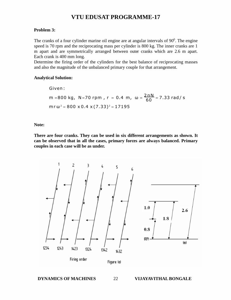
Problem 3:
The cranks of a four cylinder marine oil engine are at angular intervals of 900. The engine
speed is 70 rpm and the reciprocating mass per cylinder is 800 kg. The inner cranks are 1
m apart and are symmetrically arranged between outer cranks which are 2.6 m apart.
Each crank is 400 mm long.
Determine the firing order of the cylinders for the best balance of reciprocating masses
and also the magnitude of the unbalanced primary couple for that arrangement.
Analytical Solution:
Given:
m 800 kg, N 70 rpm , r 0.4 m, ω 2πN
7.33 rad / s
mrω 2 800 x 0.4 x (7.33) 2 17195
Note:
There are four cranks. They can be used in six different arrangements as shown. It
can be observed that in all the cases, primary forces are always balanced. Primary
couples in each case will be as under.
Taking 1 as the reference plane,
DYNAMICS OF MACHINES 22 VIJAYAVITHAL BONGALE

VTU EDUSAT PROGRAMME-17
2 2
p1 3 2 4
43761 Nm
Cp6 Cp1 43761 Nm only, since l 2 and l 4 are interchanged
l l l 17195 1.82 0.8 2.62C mr2
22
p2 4 2 3
47905 Nm
Cp5 Cp2 47905 Nm only, since l 2 and l3 are interchanged
l l 17195 2.62 0.8 1.82C mr2 l
22
p3 2 4 3l l 17195 0.82
2.6 1.82C mr2 l
19448 Nm
Cp4 Cp3 19448 Nm only, since l 4 and l3 are interchanged
Thus the best arrangement is of 3rd and 4th. The firing orders are 1423 and 1324
respectively.Unbalanced couple = 19448 N m.
Graphical solution:
DYNAMICS OF MACHINES 23 VIJAYAVITHAL BONGALE

VTU EDUSAT PROGRAMME-17
Case 3:
SIX – CYLINDER, FOUR –STROKE ENGINE
Crank positions for different cylinders for the firing order 142635 for clockwise rotation
of the crankshaft are, for
Since all the force and couple polygons close, it is inherently balanced engine for primary
and secondary forces and couples.
DYNAMICS OF MACHINES 24 VIJAYAVITHAL BONGALE
First 00
1Second 2400
2And
m1 m2 m3 m4 m5 m6
r1 r2 r3 r4 r5 r6
Third 1200
3
Fourth 1200
4
Fifth 2400
5Sixth 00
6

VTU EDUSAT PROGRAMME-17
60 60
Problem 1:
Each crank and the connecting rod of a six-cylinder four-stroke in-line engine are 60 mm
and 240 mm respectively. The pitch distances between the cylinder centre lines are 80
mm, 80 mm, 100 mm, 80 mm and 80 mm respectively. The reciprocating mass of each
cylinder is 1.4 kg. The engine speed is 1000 rpm. Determine the out-of-balance primary
and secondary forces and couples on the engine if the firing order be 142635. Take a
plane midway between the cylinders 3 and 4 as the reference plane.
Solution:
Given :
r 60mm , l connecting rod length 240 mm,
m reciprocat ing mass of each cylinder 1.4 kg ,
N 1000 rpm
We have, ω 2πN
2π x1000
104.72 rad/s
DYNAMICS OF MACHINES 25 VIJAYAVITHAL BONGALE

VTU EDUSAT PROGRAMME-17
Graphical Method:
Step 1:
Draw the primary force and primary couple polygons taking some convenient scales.
Note: For drawing these polygons take primary cranks position as the reference
NO UNBALANCED
PRIMARY FORCE
NO UNBALANCED
PRIMARY COUPLE
DYNAMICS OF MACHINES 26 VIJAYAVITHAL BONGALE
Plane Mass (m) kgRadius (r)
m
Cent.
Force/ω2
(m r )
kg m
Distance
from Ref
plane ‘2’
m
Couple/ ω2
( m r l )
kg m2
1 1.4 0.06 0.084 0.21 0.01764
2 1.4 0.06 0.084 0.13 0.01092
3 1.4 0.06 0.084 0.05 0.0042
4 1.4 0.06 0.084 -0.05 -0.0042
5 1.4 0.06 0.084 -0.13 -0.01092
6 1.4 0.06 0.084 -0.21 -0.01764

VTU EDUSAT PROGRAMME-17
Step 2:
Draw the secondary force and secondary couple polygons taking some convenient scales.
Note: For drawing these polygons take secondary cranks position as the reference
Problem 2:
60 60We have, ω
2πN2π x 2400
251.33 rad /s
The firing order of a six –cylinder vertical four-stroke in-line engine is 142635. The
piston stroke is 80 mm and length of each connecting rod is 180 mm. The pitch distances
between the cylinder centre lines are 80 mm, 80 mm, 120 mm, 80 mm and 80 mm
respectively. The reciprocating mass per cylinder is 1.2 kg and the engine speed is 2400
rpm. Determine the out-of-balance primary and secondary forces and couples on the
engine taking a plane midway between the cylinders 3 and 4 as the reference plane.
Solution:Given :
r L
80
40 mm , l connecting rod length 180 mm , 2 2
m reciprocat ing mass of each cylinder 1.2 kg ,
N 2400 rpm
NO UNBALANCED
SECONDARY FORCE
NO UNBALANCED
SECONDARY COUPLE
DYNAMICS OF MACHINES 27 VIJAYAVITHAL BONGALE

VTU EDUSAT PROGRAMME-17
Graphical Method:
Step 1:
Draw the primary force and primary couple polygons taking some convenient scales.
Note: For drawing these polygons take primary cranks position as the reference
Note: No primary unbalanced force or couple
DYNAMICS OF MACHINES 28 VIJAYAVITHAL BONGALE
Plane Mass (m) kgRadius (r)
m
Cent.
Force/ω2
(m r )
kg m
Distance
from Ref
plane ‘2’
m
Couple/ ω2
( m r l )
kg m2
1 1.2 0.04 0.048 0.22 0.01056
2 1.2 0.04 0.048 0.14 0.00672
3 1.2 0.04 0.048 0.06 0.00288
4 1.2 0.04 0.048 -0.06 -0.00288
5 1.2 0.04 0.048 -0.14 -0.00672
6 1.2 0.04 0.048 -0.22 -0.01056

VTU EDUSAT PROGRAMME-17
Step 2:
Draw the secondary force and secondary couple polygons taking some convenient scales.
Note: For drawing these polygons take secondary cranks position as the reference
Note: No secondary unbalanced force or couple
DYNAMICS OF MACHINES 29 VIJAYAVITHAL BONGALE

DYNAMICS OF MACHINES 30 VIJAYAVITHAL BONGALE
VTU EDUSAT PROGRAMME-17
Problem 3:
The stroke of each piston of a six-cylinder two-stroke inline engine is 320 mm and
the connecting rod is 800 mm long. The cylinder centre lines are spread at 500 mm.
The cranks are at 600 apart and the firing order is 145236. The reciprocating mass
per cylinder is 100 kg and the rotating parts are 50 kg per crank. Determine the out
of balance forces and couples about the mid plane if the engine rotates at 200 rpm.
Primary cranks position
Secondary cranks position
Calculation of primary forces and couples:
Total mass at the crank pin = 100 kg + 50 kg = 150 kg
Relative positions of Cranks in degrees
Firing
order
θ1 θ2 θ3 θ4 θ5 θ6
142635 0 240 120 120 240 0
145236 0 180 240 60 120 300
Relative positions of Cranks in degrees
Firing
order
θ1 θ2 θ3 θ4 θ5 θ6
142635 0 120 240 240 120 0
145236 0 0 120 120 240 240
PlaneMass (m)
kg
Radius (r)
m
Cent.
Force/ω2
(m r )
kg m
Distance
from Ref
planem
Couple/ ω2
( m r l )
kg m2
1 150 0.16 24 1.25 30
2 150 0.16 24 0.75 18
3 150 0.16 24 0.25 6
4 150 0.16 24 -0.25 -6
5 150 0.16 24 -0.75 -18
6 150 0.16 24 -1.25 -30

VTU EDUSAT PROGRAMME-17
DYNAMICS OF MACHINES 31 VIJAYAVITHAL BONGALE

VTU EDUSAT PROGRAMME-17
Calculation of secondary forces and couples:
Since rotating mass does not affect the secondary forces as they are only due to
second harmonics of the piston acceleration, the total mass at the crank is taken as
100 kg.
DYNAMICS OF MACHINES 32 VIJAYAVITHAL BONGALE
PlaneMass (m)
kg
Radius (r)
m
Cent.
Force/ω2
(m r )kg m
Distance
from Ref
planem
Couple/ ω2
( m r l )
kg m2
1 100 0.16 16 1.25 20
2 100 0.16 16 0.75 12
3 100 0.16 16 0.25 4
4 100 0.16 16 -0.25 -4
5 100 0.16 16 -0.75 -12
6 100 0.16 16 -1.25 -20

VTU EDUSAT PROGRAMME-17
BALANCING OF V – ENGINE
Two Cylinder V-engine:
A common crank OA is operated by two connecting rods. The centre lines of the two –cylinders are inclined at an angle to the X-axis.
Let be the angle moved by the crank from the X-axis.
Determination of Primary force:2
Primary force of 1 along line of stroke OB1 = mr cos( ) (1)
Primary force of 1 along X - axis = mr2 cos( ) cos (2)
2Primary force of 2 along line of stroke OB2 = mr cos( ) (3)
Primary force of 2 along X-axis = mr2 cos( )cos (4)
Total primary force along X - axis
mrω2 cos α cos(θ α) cos(θ α)
mrω2 cos α cosθ cos α sinθ sinα cos θ cos α sinθ sinαmrω2 cos α x2 cos θ cos α
2 mrω2 cos2 α cos θ (5)
DYNAMICS OF MACHINES 33 VIJAYAVITHAL BONGALE

VTU EDUSAT PROGRAMME-17
Similarly,
Total primary force along Z-axis
mrω2 cos(θα) sinα -cos(θα)sinα
mrω2 sinα (cosθcosα sinθsinα)( cosθcosα sinθsinαmrω2 sinα x2sinθsinα
2 mrω2 sin2 α sinθ (6)
Resultant Primary force
2 mrω 2 cos 2 α cos θ2 2 mrω 2 sin 2 α sinθ2
2 mrω 2 cos 2 α cos θ2 sin 2 α sinθ2 (7)
and this resultant primary force will be at angle β with the X – axis, given by,
cos 2 α cosθ
2
tanβ sin α sinθ
(8)
If 2 900, the resultant force will be equal to
2 mrω 2 cos 2 45 0 cos θ2 sin 2 45 0 sinθ2
mrω 2 (9)
and 45
DYNAMICS OF MACHINES 34 VIJAYAVITHAL BONGALE
cos 2 45 0 cosθ
2 0sinθ
tanθ (10)tanβ sin
i.e., β θ or it acts along the crank and therefore, can be completely balanced by a
is maximumcos 4 α cos 2 θ sin 4 α sin 2 θ
mass at a suitable radius diametrically opposite to the crank, such that,
m r rr mr -- - - -(11)
For a given value of α, the resultant force is maximum (Primary force), when
cos 2 α cos θ2 sin 2 α sinθ2 is maximum
or

VTU EDUSAT PROGRAMME-17
Or
dθ
d cos 4 α cos 2 θ sin 4 α sin 2 θ 0
i.e., - cos 4 α x 2 cos θ sinθ sin 4 α x 2 sinθ cos θ 0
i.e., - cos 4 α x sin2 θ sin 4 α x sin2 θ 0
i.e., sin2θ sin 4 α -cos 4 α 0
As is not zero, therefore for a given value of , the resultant primary force is
maximum when θ 0 0 .
Determination of Secondary force:
Secondary force of 1 along line of stroke OB1 is equal to
mr2
cos2( ) (1)n
2mrSecondary force of 1 along X - axis = cos2( ) cos (2)
n
Secondary force of 2 along line of stroke OB2 =
mr2
cos2( ) (3)n
2mr= cos2( )cos (4)
nPrimary force of 2 along X-axis
Therefore,
n
DYNAMICS OF MACHINES 35 VIJAYAVITHAL BONGALE
n
n
Total secondary force along X -axis
2
2
2
cos α cos 2 θ cos 2 α (5)2 mr ω
cos α (cos 2 θ cos2 α sin2 θ sin 2 α ) (cos 2 θ cos2 α sin 2 θ sin2 αmr ω
cos α cos 2 (θ α ) cos 2 (θ α )mr ω

n
VTU EDUSAT PROGRAMME-17
Similarly,
Total secondary force along Z-axis2
sinα sin2θsin2α (6)2mrω
n
Resultant Secondary force2
cos α cos2 θ cos2 α2 sin α sin2θ sin2α2 (7)2 mrω
Andcosα cos2θ cos2 α
(8)tanβ ' sinα sin2θ sin2α
If 2α 90 0 or α 45 0 ,
2
2mr
sin2 (9) n 2
2mr sin2Secondary force =
n
2
2
And tanβ ' and β ' 90 0 (10) i.e., the force acts along Z-
axis and is a harmonic force and special methods are needed to balance it.
Problem 1:
The cylinders of a twin V-engine are set at 600 angle with both pistons connected to a
single crank through their respective connecting rods. Each connecting rod is 600 mm
long and the crank radius is 120 mm. The total rotating mass is equivalent to 2 kg at the
crank radius and the reciprocating mass is 1.2 kg per piston. A balance mass is also fitted
opposite to the crank equivalent to 2.2 kg at a radius of 150 mm. Determine the
maximum and minimum values of the primary and secondary forces due to inertia of the
reciprocating and the rotating masses if the engine speed is 800 mm.
Solution:
Given :
m reciprocat ing mass of each piston 1.2 kg
M equivalent rotating mass 2 kg
m C balancing mass 2.2 kg, rC 150 mm
l connecting rod length 600 mm
r crank radius 120 mm
N 800 rpm
We have, ω 2πN
2π x 800
83.78 rad /s and n l
6005
60 60 r 120
DYNAMICS OF MACHINES 36 VIJAYAVITHAL BONGALE

VTU EDUSAT PROGRAMME-17
Primary Force:
Total primary force along X - axis 2 mrω 2 cos 2 α cos θ������������(1)
C C m r ω 2 cos θ (3)
Centrifuga l force due to rotating mass along X axis
Mrω 2 cos θ (2)
Centrifuga l force due to balancing mass along X axis
Therefore total unbalance force along X –axis = (1) + (2) + (3)
That isTotal Unbalance force along X axis
C C
2 2
C C
ω cosθ 2 mr cos α Mr -m r 2 mrω2 cos2 α cosθMrω2 cosθ m r ω 2 cosθ
83.782 cosθ2x1.2x0.12xcos2 30 0 2x0.122.2x0.15 83.782 cosθ0.216 0.24 -0.33 884.41 cosθ N - - - - - - -(4)
Total primary force along Z - axis 2 mrω 2 sin2 α sinθ (5)
DYNAMICS OF MACHINES 37 VIJAYAVITHAL BONGALE

VTU EDUSAT PROGRAMME-17
Centrifuga l force due to rotating mass along Z axis
Mrω 2 sinθ (6)
C C
Centrifuga l force due to balancing mass along Z axis2
m r ω sinθ (7)
Therefore total unbalance force along Z –axis = (5) + (6) + (7)
That is
Total Unbalance force along Z - axis
C C
2 2
C C
ω sinθ 2 mr sin α Mr -m r 2 mrω2 sin2 α sinθMrω2 sinθ m r ω 2 sinθ
884.41 N (10)
DYNAMICS OF MACHINES 38 VIJAYAVITHAL BONGALE
766219.25 15961.8
83.782 sinθ2x1.2x0.12xsin2 30 0 2x0.122.2x0.15 83.782 sinθ0.072 0.24 -0.33 -126.34 sinθ N - - - - - - -(8)
Resultant Primary force
884.41 cos θ2 -126.34 sinθ2
782181.05cos 2 θ 15961.8sin 2 θ
766219.25cos 2 θ 15961.8 (9)
This is maximum, when 00and minimum, when 900
Maximum Primary force, i.e., when θ 0 0
And Minimum Primary force, i.e., when θ 90 0
766219.25 cos 2 90 0 15961.8 126.34 N (11)
Secondary force:
The rotating masses do not affect the secondary forces as they are only due to second
harmonics of the piston acceleration.

5
n
VTU EDUSAT PROGRAMME-17
Resultant Secondary force
2 x1.2x0.12x(83.78)2
2
cos30 2 cos2θcos60 2 2
sin30 0 sin2θsin60 0 2
cosα cos2θcos2α2 sinα sin2θsin2α22mrω
404.3 0.1875 (cos2θθ2 0.1875 ( sin2θθ2 (12)
This is maximum, when 00and minimum, when 1800
Maximum secondary force, i.e., when θ 0 0
404.3 0.1875 ( cos0 0 ) 2 0.1875 ( sin 0 0) 2 175.07 N (13)
And Minimum secondary force, i.e., when θ 180 0
404.3 0.1875 ( cos180 0) 2 0.1875 ( sin180 0 ) 2 175.07 N (14)
BALANCING OF W, V-8 AND V-12 – ENGINES
BALANCING OF W ENGINE
In this engine three connecting rods are operated by a common crank.
Total primary force along X -axis
mr ω 2 cos θ2 cos 2 α 1 (1)
Total primary force along Z-axis wi l l be same as in the V twin engine,
(since the primary force of 3 along Z axis is zero)
2 mr ω 2 sin 2 α sin θ (2)
Resultant Primary force
mrω 2 cos θ2cos 2 α 12 2sin 2 αsinθ2 (3)
and this resultant primary force will be at angle β with the X – axis, given by,
DYNAMICS OF MACHINES 39 VIJAYAVITHAL BONGALE

VTU EDUSAT PROGRAMME-17
2sin α sinθ2
(4)cosθ2cos 2 α 1
tanβ
If 600,
Resultant Primary force
3 and
mrω 2 (5) 2
tanβ tanθ (6)
β θi.e., or it acts along the crank and therefore, can be completely balanced by a
n
mass at a suitable radius diametrically opposite to the crank, such that,
m r rr mr - - - - -(7)
Total secondary force along X -axis
2
2mr ωcos 2θ cos α cos 2 α 1 (8)
2sin α sin2αsin2θ cos2θn
Total secondary force along Z –direction will be same as in the V-twin engine.
Resultant secondary force
222
(9)2cos α cos2α 1 mrω
(10) 2sinα sin2θ sin2α
cos2θ2cosα cos2 α 1tanβ '
2n
If 600,
Secondary force along X -axis
2
cos 2θ (11)mr ω
2n
DYNAMICS OF MACHINES 40 VIJAYAVITHAL BONGALE
Secondary force along Z-axis
2
sin2θ (12)3mr ω
It is not possible to balance these forces simultaneously

VTU EDUSAT PROGRAMME-17
V-8 ENGINE
It consists of two banks of four cylinders each. The two banks are inclined to each other
in the shape of V. The analysis will depend on the arrangement of cylinders in each bank.
V-12 ENGINE
It consists of two banks of six cylinders each. The two banks are inclined to each other in
the shape of V. The analysis will depend on the arrangement of cylinders in each bank.
If the cranks of the six cylinders on one bank are arranged like the completely balanced
six cylinder, four stroke engine then, there is no unbalanced force or couple and thus the
engine is completely balanced.
BALANCING OF RADIAL ENGINES:
It is a multicylinder engine in which all the connecting rods are connected to a common
crank.
DYNAMICS OF MACHINES 41 VIJAYAVITHAL BONGALE

DYNAMICS OF MACHINES 42 VIJAYAVITHAL BONGALE
VTU EDUSAT PROGRAMME-17
Direct and reverse crank method of analysis:
In this all the forces exists in the same plane and hence no couple exist.
In a reciprocating engine the primary force is given by, mr2 cos which acts along
the line of stroke.
In direct and reverse crank method of analysis, a force identical to this force is generated
by two masses as follows.
1.A mass m/2, placed at the crank pin A and rotating at an angular velocity ω in the
counter clockwise direction.
2.A mass m/2, placed at the crank pin of an imaginary crank OA’ at the same angular
position as the real crank but in the opposite direction of the line of stroke. It is assumed
to rotate at an angular velocity ω in the clockwise direction (opposite).3. While rotating, the two masses coincide only on the cylinder centre line.
The components of the centrifugal forces due to rotating masses along the line of stroke
are,
Due to mass at A m
r2 cos2
Due to mass at A ' m
r2 cos2
Thus, total force along the line of stroke = mr2 cos which is equal to the primary
force.
At any instant, the components of the centrifugal forces of these masses normal to the
line of stroke will be equal and opposite.
The crank rotating in the direction of engine rotation is known as the direct crank and
the imaginary crank rotating in the opposite direction is known as the reverse crank.
Now,
Secondary accelerating force is
mr2 cos2 mr(2)2 cos2
n 4n
mr
(2)2 cos24n

VTU EDUSAT PROGRAMME-17
This force can also be generated by two masses in a similar way as follows.
1. A mass m/2, placed at the end of direct secondary crank of lengthr
4nat an angle 2θ
and rotating at an angular velocity 2ω in the counter clockwise direction.
r
4nat an angle -2θ2. A mass m/2, placed at the end of reverse secondary crank of length
and rotating at an angular velocity 2ω in the clockwise direction.
The components of the centrifugal forces due to rotating masses along the line of stroke
are,
2 4n 2n
2
Due to mass at C m r
(2ω)2 cos2θ mrω
cos2θ
r
2 4n 2n
2
Due to mass at C' m
(2ω)2 cos2θ mrω
cos2θ
Thus, total force along the line of stroke =
2 4n n
DYNAMICS OF MACHINES 43 VIJAYAVITHAL BONGALE
2m r mrω2x (2ω)2 cos2θ cos2θ which is equal to the secondary force.
References:
1.Theory of Machines by S.S.Rattan, Third Edition, Tata McGraw Hill Education
Private Limited.
2.Kinematics and Dynamics of Machinery by R. L. Norton, First Edition in SI units, Tata
McGraw Hill Education Private Limited.